eao series 56
DESCRIPTION
http://www.eao.com/global/en/Catalogues/PDF_Data_with_drawings/EAO_Recommended_Series/EAO-Series-56-Full-Data.pdfTRANSCRIPT

EAO – Your Expert Partner for Human Machine Interfaces
EAO Product Information
Series 56


56Switches and Indicators
56Contents
203.2010
Description ...................................................................................................... 3
Product Assembly .......................................................................................... 4
Mounting instruction ...................................................................................... 6
Devices front mounting.................................................................................. 7
Devices rear mounting ................................................................................. 15
Devices glass mounting............................................................................... 21
Accessories................................................................................................... 26
Technical Data............................................................................................... 29
Typical Applications..................................................................................... 32
Application guidelines.................................................................................. 34
Marking .......................................................................................................... 35
Drawings........................................................................................................ 36
Index............................................................................................................... 51

303.2010
56Description
General notesThe series 56 is designed as a door pushbutton for public transport applications. We have implemented an exellent tactile feedback - our common mechanical switch!The pushbutton consists of a switching unit with LED illumination, lens and connection cable. If you use the front panel mounting, the screws are covered by the raised front bezel. If a flush mounted version is needed, you don't need the front bezel and can be mounted easely from the back side.The door open pushbutton can be mounted either as a double or as a single pushbutton function. For covering the fixing screws, the round front bezel is needed.Additional to the push-buttons, the range is completed by flush or raised conical indicator. The raised conical indicators offer high-visibility illumination even from a distance or from side view with a wide angle of 180° circumferential visibility.
Luminosity and wave length scattering caused by the technology used in the LED manufacturing processes may lead to visual differences in our products.Anodized aluminium parts can have visible variations due production-technical reasons.
Multi-Tone Sound ModuleThe Sound Module MTSM can be programmed (customized tone sequences are provided when desired by EAO or directly by the customer by means of a tone editor program), to emit a clear warning sound adapted to a particular operating environment.Up to five different tone sequences can be played in any sequence at different volumes, durations and intervals to create a unique sequence. A set of standard sounds is pre-programmed for equipment in Transport and Machinery applications.The Sound Module shares the same design and dimensions of other Series 56 product.Fast front mounting into panel with 3 fixing screws (supplied).
Specimen order0
We reserve the right to modify technical dataAll dimensions in mm
Product Information Single side pushbutton :- Single side pushbutton front mounting,
lens alu blue raised, LED 8 green 2 red, 24 VDC, cable 200 mm with plug-in housing 2.8 x 0.8 mm
56-130.22.200.21.04
Essential accessories :- Front bezel metal mat-chrom plated,
87 mm dia.56-3600
56Product Assembly
403.2010
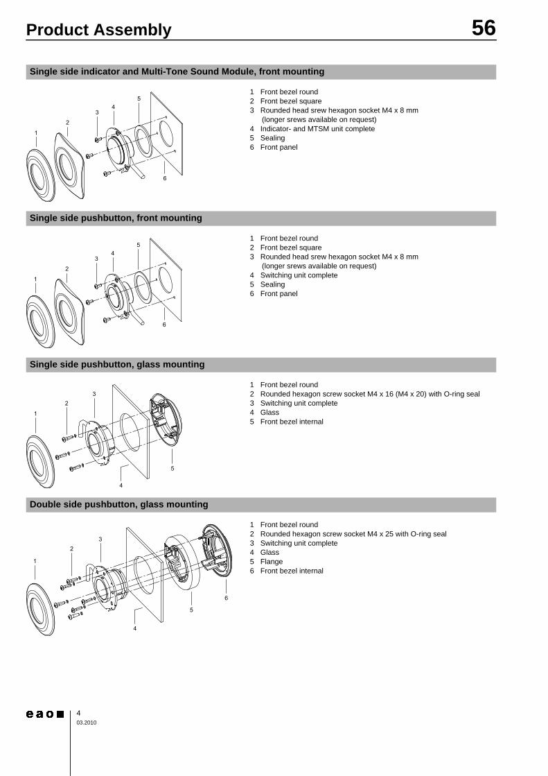
Single side indicator and Multi-Tone Sound Module, front mounting
0 1 Front bezel round2 Front bezel square3 Rounded head srew hexagon socket M4 x 8 mm
(longer srews available on request)4 Indicator- and MTSM unit complete5 Sealing6 Front panel
Single side pushbutton, front mounting
0 1 Front bezel round2 Front bezel square3 Rounded head srew hexagon socket M4 x 8 mm
(longer srews available on request)4 Switching unit complete5 Sealing6 Front panel
Single side pushbutton, glass mounting
0 1 Front bezel round2 Rounded hexagon screw socket M4 x 16 (M4 x 20) with O-ring seal3 Switching unit complete4 Glass5 Front bezel internal
Double side pushbutton, glass mounting
0 1 Front bezel round2 Rounded hexagon screw socket M4 x 25 with O-ring seal3 Switching unit complete4 Glass5 Flange6 Front bezel internal

56Product Assembly
503.2010
Single side indicator and Multi-Tone Sounde Module, front mounting
0 1 Front panel2 Seals, spacers and reinforcement plate
(see Mounting set Nr. 56-991)3 Indicator- and MTSM unit complete
Single side pushbutton, front mounting
0 1 Front panel2 Seals, spacers and reinforcement plate
(see Mounting set Nr. 56-991)3 Switching unit complete
2
2
2
1
3
2
2
2
1
3
56Mounting instruction
603.2010
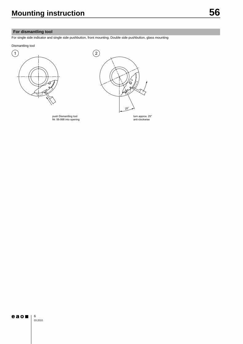
For single side indicator and single side pushbutton, front mounting; Double side pushbutton, glass mounting
Dismantling tool0
For dismantling tool

56Devices front mounting
703.2010
Indicator unit usable with front bezel : b 87 x 87 mm | 87 mm dia.Order front bezel separately
Essential Accessories:d Front bezel page 26Continuation see next page
Standard version:- Cable length 200 mm; AMP plug-in housing 2.8 x 0.8 mmOther options available on request:- Special cable lengths; special plug-in housings- Operation voltage 110 VDCFilm inserts :For layout possibilities and price clarifications contact our distributor or subsidiary In addition the following data are necessary :1. Text (standard lettering Arial, other lettering on request)2. Text illumination color (green, yellow, red or blue, background black)3. Mounting position4. Symbols with sketch, sample or DXF file Component layout from page 36, Mounting dimensions from page 37, Technical drawing from page 42, Circuit drawing from page 49
Single side indicator
Fron
t pro
tect
ion
Illum
inat
ion
Marking Typ-Nr. Com
pone
nt la
yout
Mou
ntin
g di
men
sion
sTe
chni
cal d
raw
ing
Circ
uit d
raw
ing
e
Single side indicator Operating voltage : 24 VDC
IP 67 LED blue 1 line 56-8213.91 1 3 5 7 0.0452 lines 56-8213.92 1 3 5 7 0.0453 lines 56-8213.93 1 3 5 7 0.045symbol 56-8213.90 1 3 5 7 0.045without 56-8213.8 1 3 5 7 0.045
LED green 1 line 56-2213.91 1 3 5 7 0.0452 lines 56-2213.92 1 3 5 7 0.0453 lines 56-2213.93 1 3 5 7 0.045symbol 56-2213.90 1 3 5 7 0.045without 56-2213.8 1 3 5 7 0.045
LED red 1 line 56-3213.91 1 3 5 7 0.0452 lines 56-3213.92 1 3 5 7 0.0453 lines 56-3213.93 1 3 5 7 0.045symbol 56-3213.90 1 3 5 7 0.045without 56-3213.8 1 3 5 7 0.045
LED white without 56-9213.8 1 3 5 7 0.045LED yellow 1 line 56-6213.91 1 3 5 7 0.045
2 lines 56-6213.92 1 3 5 7 0.0453 lines 56-6213.93 1 3 5 7 0.045symbol 56-6213.90 1 3 5 7 0.045without 56-6213.8 1 3 5 7 0.045

56Devices front mounting
803.2010
Indicator unit usable with front bezel : b 87 x 87 mm | 87 mm dia.Order front bezel separately
Essential Accessories:d Front bezel page 26Continuation see next page
Standard version:- Cable length 200 mm; AMP plug-in housing 2.8 x 0.8 mmOther options available on request:- Special cable lengths; special plug-in housingsComponent layout from page 36, Mounting dimensions from page 37, Technical drawing from page 42, Circuit drawing from page 49
Single side indicator raised conical
Fron
t pro
tect
ion
Lens cap Illumination Typ-Nr. Com
pone
nt la
yout
Mou
ntin
g di
men
sion
sTe
chni
cal d
raw
ing
Circ
uit d
raw
ing
e
Single side indicator raised conical Operating voltage : 110 VDC
IP 67 Plastic colourless raised LED blue 56-8913.70 1 3 8 7 0.040LED green 56-2913.70 1 3 8 7 0.040LED orange 56-4913.70 1 3 8 7 0.040LED red 56-3913.70 1 3 8 7 0.040LED white 56-9913.70 1 3 8 7 0.040LED yellow 56-6913.70 1 3 8 7 0.040
Operating voltage : 24 VDC IP 67 Plastic colourless raised LED blue 56-8213.70 1 3 8 7 0.040LED green 56-2213.70 1 3 8 7 0.040LED orange 56-4213.70 1 3 8 7 0.040LED red 56-3213.70 1 3 8 7 0.040LED white 56-9213.70 1 3 8 7 0.040LED yellow 56-6213.70 1 3 8 7 0.040

56Devices front mounting
903.2010
Continuation see next page
Lens can be markedPushbutton unit usable with front bezel : b 87 x 87 mm | 87 mm dia.Order front bezel separately
Essential Accessories:d Front bezel page 26Continuation see next page
Single side pushbutton
Fron
t pro
tect
ion
Lens Colour Display Typ-Nr. Com
pone
nt la
yout
Mou
ntin
g di
men
sion
sTe
chni
cal d
raw
ing
Circ
uit d
raw
ing
e
Single side pushbutton Operating voltage : 24 VDC
IP 67 Aluminium blue raised - LED 8 green 56-130.22.200.23.04 2 2 4 2 0.100LED 8 green 2 red 56-130.22.200.21.04 2 2 4 1 0.100LED 8 red 56-130.22.200.24.04 2 2 4 2 0.100LED 8 red 2 green 56-130.22.200.22.04 2 2 4 1 0.100LED 8 yellow 56-130.22.200.25.04 2 2 4 2 0.100without 56-030.04.200.00.04 3 2 4 3 0.100
Aluminium green raised - LED 8 green 56-130.22.200.23.03 2 2 4 2 0.100LED 8 green 2 red 56-130.22.200.21.03 2 2 4 1 0.100LED 8 red 56-130.22.200.24.03 2 2 4 2 0.100LED 8 red 2 green 56-130.22.200.22.03 2 2 4 1 0.100LED 8 yellow 56-130.22.200.25.03 2 2 4 2 0.100without 56-030.04.200.00.03 3 2 4 3 0.100
Aluminium natural flush - LED 8 green 56-120.22.200.23.05 2 2 4 2 0.100LED 8 green 2 red 56-120.22.200.21.05 2 2 4 1 0.100LED 8 red 56-120.22.200.24.05 2 2 4 2 0.100LED 8 red 2 green 56-120.22.200.22.05 2 2 4 1 0.100LED 8 yellow 56-120.22.200.25.05 2 2 4 2 0.100without 56-020.04.200.00.05 3 2 4 3 0.100
Aluminium natural raised - LED 8 green 56-130.22.200.23.05 2 2 4 2 0.100LED 8 green 2 red 56-130.22.200.21.05 2 2 4 1 0.100LED 8 red 56-130.22.200.24.05 2 2 4 2 0.100LED 8 red 2 green 56-130.22.200.22.05 2 2 4 1 0.100LED 8 yellow 56-130.22.200.25.05 2 2 4 2 0.100without 56-030.04.200.00.05 3 2 4 3 0.100
Aluminium red raised - LED 8 green 56-130.22.200.23.01 2 2 4 2 0.100LED 8 green 2 red 56-130.22.200.21.01 2 2 4 1 0.100LED 8 red 56-130.22.200.24.01 2 2 4 2 0.100LED 8 red 2 green 56-130.22.200.22.01 2 2 4 1 0.100LED 8 yellow 56-130.22.200.25.01 2 2 4 2 0.100without 56-030.04.200.00.01 3 2 4 3 0.100
Aluminium yellow raised - LED 8 green 56-130.22.200.23.02 2 2 4 2 0.100LED 8 green 2 red 56-130.22.200.21.02 2 2 4 1 0.100LED 8 red 56-130.22.200.24.02 2 2 4 2 0.100LED 8 red 2 green 56-130.22.200.22.02 2 2 4 1 0.100LED 8 yellow 56-130.22.200.25.02 2 2 4 2 0.100without 56-030.04.200.00.02 3 2 4 3 0.100

56Devices front mounting
1003.2010
Continued from previous page
Standard version:- Cable length 200 mm; AMP plug-in housing 2.8 x 0.8 mmOther options available on request:- Special cable lengths; special plug-in housings- Operation voltage 36, 48, 72, 96, 110 VDC- Customer specific lens colours- Various symbolsComponent layout from page 36, Mounting dimensions from page 37, Technical drawing from page 42, Circuit drawing from page 49
Single side pushbutton Operating voltage : 24 VDC
IP 67 Plastic blue flush RAL 5017 LED 8 green 56-110.22.200.23.04 2 2 4 2 0.100LED 8 green 2 red 56-110.22.200.21.04 2 2 4 1 0.100LED 8 red 56-110.22.200.24.04 2 2 4 2 0.100LED 8 red 2 green 56-110.22.200.22.04 2 2 4 1 0.100LED 8 yellow 56-110.22.200.25.04 2 2 4 2 0.100without 56-010.04.200.00.04 3 2 4 3 0.100
Plastic green flush RAL 6024 LED 8 green 56-110.22.200.23.03 2 2 4 2 0.100LED 8 green 2 red 56-110.22.200.21.03 2 2 4 1 0.100LED 8 red 56-110.22.200.24.03 2 2 4 2 0.100LED 8 red 2 green 56-110.22.200.22.03 2 2 4 1 0.100LED 8 yellow 56-110.22.200.25.03 2 2 4 2 0.100without 56-010.04.200.00.03 3 2 4 3 0.100
Plastic red flush RAL 3020 LED 8 green 56-110.22.200.23.01 2 2 4 2 0.100LED 8 green 2 red 56-110.22.200.21.01 2 2 4 1 0.100LED 8 red 56-110.22.200.24.01 2 2 4 2 0.100LED 8 red 2 green 56-110.22.200.22.01 2 2 4 1 0.100LED 8 yellow 56-110.22.200.25.01 2 2 4 2 0.100without 56-010.04.200.00.01 3 2 4 3 0.100
Plastic yellow flush RAL 1023 LED 8 green 56-110.22.200.23.02 2 2 4 2 0.100LED 8 green 2 red 56-110.22.200.21.02 2 2 4 1 0.100LED 8 red 56-110.22.200.24.02 2 2 4 2 0.100LED 8 red 2 green 56-110.22.200.22.02 2 2 4 1 0.100LED 8 yellow 56-110.22.200.25.02 2 2 4 2 0.100without 56-010.04.200.00.02 3 2 4 3 0.100
Fron
t pro
tect
ion
Lens Colour Display Typ-Nr. Com
pone
nt la
yout
Mou
ntin
g di
men
sion
sTe
chni
cal d
raw
ing
Circ
uit d
raw
ing
e

56Devices front mounting
1103.2010
Continuation see next page
Continuation see next page
Multi-Tone Sound Module 5-tone sequences with front bezel
Fron
t pro
tect
ion
Front bezel Speaker cap Mar
king
Tone
seq
uenc
e
b 87 x 87 mmTyp-Nr.
Ø 87 mmTyp-Nr. C
ompo
nent
layo
utM
ount
ing
dim
ensi
ons
Tech
nica
l dra
win
g
Circ
uit d
raw
ing
e
Multi-Tone Sound Module 5-tone sequences with front bezel Operating voltage: 24 VDC
IP 69K Metalmat-chrome
Plastic black flush Symbol T 56-61011-00.12 4 3 10 4 0.142Plastic black raised Symbol M 56-61011-00.7 4 3 11 4 0.145
without M 56-61001-00.6 4 3 11 4 0.145T 56-61001-00.11 4 3 11 4 0.145
Plastic blue Plastic black flush Symbol T 56-61011-00.11 4 3 10 4 0.083Plastic black raised Symbol M 56-61011-00.6 4 3 11 4 0.086
without M 56-61001-00.5 4 3 11 4 0.086T 56-61001-00.10 4 3 11 4 0.086
Plastic green Plastic black flush Symbol T 56-61011-00.10 4 3 10 4 0.083Plastic black raised Symbol M 56-61011-00.5 4 3 11 4 0.086
without M 56-61001-00.4 4 3 11 4 0.086T 56-61001-00.9 4 3 11 4 0.086
Plastic red Plastic black flush Symbol T 56-61011-00.8 4 3 10 4 0.083Plastic black raised Symbol M 56-61011-00.3 4 3 11 4 0.086
without M 56-61001-00.2 4 3 11 4 0.086T 56-61001-00.7 4 3 11 4 0.086
Plastic yellow Plastic black flush Symbol T 56-61011-00.9 4 3 10 4 0.083Plastic black raised Symbol M 56-61011-00.4 4 3 11 4 0.086
without M 56-61001-00.3 4 3 11 4 0.086T 56-61001-00.8 4 3 11 4 0.086
Metalmat-chrome
Plastic black flush Symbol T 56-61011-00.26 4 3 10 4 0.127Plastic black raised Symbol M 56-61011-00.19 4 3 11 4 0.130
without M 56-61001-00.18 4 3 11 4 0.130T 56-61001-00.25 4 3 11 4 0.130
Plastic black Plastic black flush Symbol T 56-61011-00.21 4 3 10 4 0.078Plastic black raised Symbol M 56-61011-00.14 4 3 11 4 0.078
without M 56-61001-00.13 4 3 11 4 0.078T 56-61001-00.20 4 3 11 4 0.078
Plastic blue Plastic black flush Symbol T 56-61011-00.25 4 3 10 4 0.078Plastic black raised Symbol M 56-61011-00.18 4 3 11 4 0.078
without M 56-61001-00.17 4 3 11 4 0.078T 56-61001-00.24 4 3 11 4 0.078
Plastic green Plastic black flush Symbol T 56-61011-00.23 4 3 10 4 0.078Plastic black raised Symbol M 56-61011-00.16 4 3 11 4 0.078
without M 56-61001-00.15 4 3 11 4 0.078T 56-61001-00.22 4 3 11 4 0.078

56Devices front mounting
1203.2010
Continued from previous page
Standard version:- Cable length 200 mm; six-core; without connector- Volume control by switch on back of 56 MTSM- Five pre-programmed standard tone sequences for "Transportation (T)"- Five pre-programmed standard tone sequences for "Machinery (M)"- Customer specific tone sequences are factory-programmed by EAODetailed data regarding the 56 MTSM module can be found in the section "Typical Applications"Other options available on request:- Special cable lengths; special plug-in housings- Customer specific tone sequences by programmable means of EAO Tone Editor SoftwareTone sequence: T = Transportation 1-5, M = Machinery 6-10Component layout from page 36, Mounting dimensions from page 37, Technical drawing from page 42, Circuit drawing from page 49
Multi-Tone Sound Module 5-tone sequences with front bezel Operating voltage: 24 VDC
IP 69K Plastic orange Plastic black flush Symbol T 56-61011-00.24 4 3 10 4 0.078Plastic black raised Symbol M 56-61011-00.17 4 3 11 4 0.078
without M 56-61001-00.16 4 3 11 4 0.078T 56-61001-00.23 4 3 11 4 0.078
Plastic red Plastic black flush Symbol T 56-61011-00.20 4 3 10 4 0.078Plastic black raised Symbol M 56-61011-00.13 4 3 11 4 0.078
without M 56-61001-00.12 4 3 11 4 0.078T 56-61001-00.19 4 3 11 4 0.078
Plastic yellow Plastic black flush Symbol T 56-61011-00.22 4 3 10 4 0.078Plastic black raised Symbol M 56-61011-00.15 4 3 11 4 0.078
without M 56-61001-00.14 4 3 11 4 0.078T 56-61001-00.21 4 3 11 4 0.078
Fron
t pro
tect
ion
Front bezel Speaker cap Mar
king
Tone
seq
uenc
e
b 87 x 87 mmTyp-Nr.
Ø 87 mmTyp-Nr. C
ompo
nent
layo
utM
ount
ing
dim
ensi
ons
Tech
nica
l dra
win
g
Circ
uit d
raw
ing
e
56Devices front mounting
1303.2010
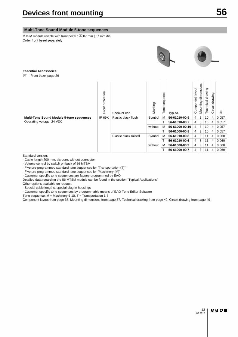
MTSM module usable with front bezel : a 87 mm | 87 mm dia.Order front bezel separately
Essential Accessories:d Front bezel page 26Continuation see next page
Standard version:- Cable length 200 mm; six-core; without connector- Volume control by switch on back of 56 MTSM- Five pre-programmed standard tone sequences for "Transportation (T)"- Five pre-programmed standard tone sequences for "Machinery (M)"- Customer specific tone sequences are factory-programmed by EAODetailed data regarding the 56 MTSM module can be found in the section "Typical Applications"Other options available on request:- Special cable lengths; special plug-in housings- Customer specific tone sequences by programmable means of EAO Tone Editor SoftwareTone sequence: M = Machinery 6-10, T = Transportation 1-5Component layout from page 36, Mounting dimensions from page 37, Technical drawing from page 42, Circuit drawing from page 49
Multi-Tone Sound Module 5-tone sequences
Fron
t pro
tect
ion
Speaker cap Mar
king
Tone
seq
uenc
e
Typ-Nr. Com
pone
nt la
yout
Mou
ntin
g di
men
sion
s
Tech
nica
l dra
win
g
Circ
uit d
raw
ing
e
Multi-Tone Sound Module 5-tone sequences Operating voltage: 24 VDC
IP 69K Plastic black flush Symbol M 56-61010-00.9 4 3 10 4 0.057T 56-61010-00.7 4 3 10 4 0.057
without M 56-61000-00.10 4 3 10 4 0.057T 56-61000-00.8 4 3 10 4 0.057
Plastic black raised Symbol M 56-61010-00.8 4 3 11 4 0.060T 56-61010-00.6 4 3 11 4 0.060
without M 56-61000-00.9 4 3 11 4 0.060T 56-61000-00.7 4 3 11 4 0.060
56Devices front mounting
1403.2010
MTSM module usable with front bezel : a 87 mm | 87 mm dia.Order front bezel separately
Essential Accessories:d Front bezel page 26Continuation see next page
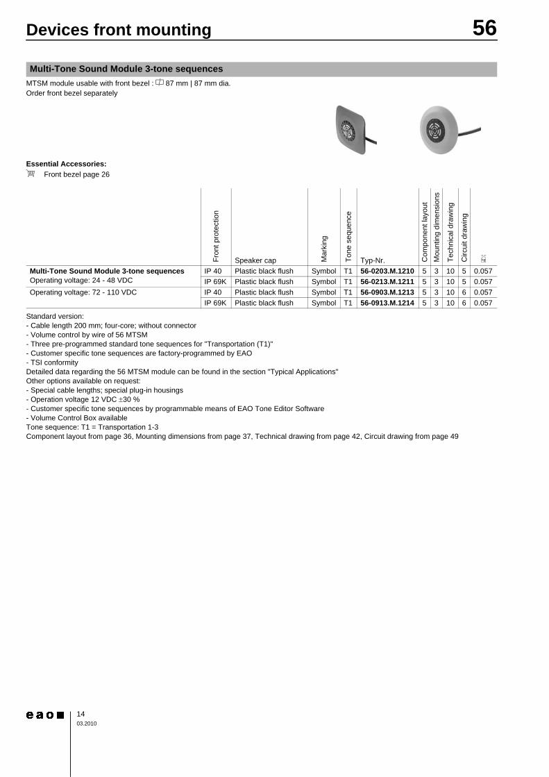
Standard version:- Cable length 200 mm; four-core; without connector- Volume control by wire of 56 MTSM- Three pre-programmed standard tone sequences for "Transportation (T1)"- Customer specific tone sequences are factory-programmed by EAO- TSI conformityDetailed data regarding the 56 MTSM module can be found in the section "Typical Applications"Other options available on request:- Special cable lengths; special plug-in housings- Operation voltage 12 VDC ±30 %- Customer specific tone sequences by programmable means of EAO Tone Editor Software- Volume Control Box availableTone sequence: T1 = Transportation 1-3Component layout from page 36, Mounting dimensions from page 37, Technical drawing from page 42, Circuit drawing from page 49
Multi-Tone Sound Module 3-tone sequences
Fron
t pro
tect
ion
Speaker cap Mar
king
Tone
seq
uenc
e
Typ-Nr. Com
pone
nt la
yout
Mou
ntin
g di
men
sion
s
Tech
nica
l dra
win
g
Circ
uit d
raw
ing
e
Multi-Tone Sound Module 3-tone sequences Operating voltage: 24 - 48 VDC
IP 40 Plastic black flush Symbol T1 56-0203.M.1210 5 3 10 5 0.057IP 69K Plastic black flush Symbol T1 56-0213.M.1211 5 3 10 5 0.057
Operating voltage: 72 - 110 VDC IP 40 Plastic black flush Symbol T1 56-0903.M.1213 5 3 10 6 0.057IP 69K Plastic black flush Symbol T1 56-0913.M.1214 5 3 10 6 0.057

56Devices rear mounting
1503.2010
Continuation see next page
Standard version:- Cable length 200 mm; AMP plug-in housing 2.8 x 0.8 mmOther options available on request:- Special cable lengths; special plug-in housings- Operation voltage 110 VDCFilm inserts :For layout possibilities and price clarifications contact our distributor or subsidiary In addition the following data are necessary :1. Text (standard lettering Arial, other lettering on request)2. Text illumination color (green, yellow, red or blue, background black)3. Mounting position4. Symbols with sketch, sample or DXF file Component layout from page 36, Mounting dimensions from page 37, Technical drawing from page 42, Circuit drawing from page 49
Single side indicator
Fron
t pro
tect
ion
Illum
inat
ion
Mar
king
Ø 43 mmTyp-Nr. C
ompo
nent
layo
utM
ount
ing
dim
ensi
ons
Tech
nica
l dra
win
gC
ircui
t dra
win
g
e
Single side indicator Operating voltage : 24 VDC
IP 67 LED blue 1 line 56-8213.91 1 4 6 7 0.0452 lines 56-8213.92 1 4 6 7 0.0453 lines 56-8213.93 1 4 6 7 0.045symbol 56-8213.90 1 4 6 7 0.045without 56-8213.8 1 4 6 7 0.045
LED green 1 line 56-2213.91 1 4 6 7 0.0452 lines 56-2213.92 1 4 6 7 0.0453 lines 56-2213.93 1 4 6 7 0.045symbol 56-2213.90 1 4 6 7 0.045without 56-2213.8 1 4 6 7 0.045
LED red 1 line 56-3213.91 1 4 6 7 0.0452 lines 56-3213.92 1 4 6 7 0.0453 lines 56-3213.93 1 4 6 7 0.045symbol 56-3213.90 1 4 6 7 0.045without 56-3213.8 1 4 6 7 0.045
LED white without 56-9213.8 1 4 6 7 0.045LED yellow 1 line 56-6213.91 1 4 6 7 0.045
2 lines 56-6213.92 1 4 6 7 0.0453 lines 56-6213.93 1 4 6 7 0.045symbol 56-6213.90 1 4 6 7 0.045without 56-6213.8 1 4 6 7 0.045

56Devices rear mounting
1603.2010
Continuation see next page
Standard version:- Cable length 200 mm; AMP plug-in housing 2.8 x 0.8 mmOther options available on request:- Special cable lengths; special plug-in housingsComponent layout from page 36, Mounting dimensions from page 37, Technical drawing from page 42, Circuit drawing from page 49
Single side indicator raised conical
Fron
t pro
tect
ion
Lens cap IlluminationØ 43 mmTyp-Nr. C
ompo
nent
layo
utM
ount
ing
dim
ensi
ons
Tech
nica
l dra
win
gC
ircui
t dra
win
g
e
Single side indicator raised conical Operating voltage : 110 VDC
IP 67 Plastic colourless LED blue 56-8913.70 1 4 9 7 0.040LED green 56-2913.70 1 4 9 7 0.040LED orange 56-4913.70 1 4 9 7 0.040LED red 56-3913.70 1 4 9 7 0.040LED white 56-9913.70 1 4 9 7 0.040LED yellow 56-6913.70 1 4 9 7 0.040
Operating voltage : 24 VDC IP 67 Plastic colourless LED blue 56-8213.70 1 4 9 7 0.040LED green 56-2213.70 1 4 9 7 0.040LED orange 56-4213.70 1 4 9 7 0.040LED red 56-3213.70 1 4 9 7 0.040LED white 56-9213.70 1 4 9 7 0.040LED yellow 56-6213.70 1 4 9 7 0.040

56Devices rear mounting
1703.2010
Continuation see next page
Lens can be marked
Continuation see next page
Single side pushbutton
Fron
t pro
tect
ion
Lens Colour DisplayØ 43 mmTyp-Nr. C
ompo
nent
layo
utM
ount
ing
dim
ensi
ons
Tech
nica
l dra
win
gC
ircui
t dra
win
g
e
Single side pushbutton Operating voltage : 24 VDC
IP 67 Aluminium blue raised - LED 8 green 56-130.22.200.23.04 2 1 3 2 0.100LED 8 green 2 red 56-130.22.200.21.04 2 1 3 1 0.100LED 8 red 56-130.22.200.24.04 2 1 3 2 0.100LED 8 red 2 green 56-130.22.200.22.04 2 1 3 1 0.100LED 8 yellow 56-130.22.200.25.04 2 1 3 2 0.100without 56-030.04.200.00.04 3 1 3 3 0.100
Aluminium green raised - LED 8 green 56-130.22.200.23.03 2 1 3 2 0.100LED 8 green 2 red 56-130.22.200.21.03 2 1 3 1 0.100LED 8 red 56-130.22.200.24.03 2 1 3 2 0.100LED 8 red 2 green 56-130.22.200.22.03 2 1 3 1 0.100LED 8 yellow 56-130.22.200.25.03 2 1 3 2 0.100without 56-030.04.200.00.03 3 1 3 3 0.100
Aluminium natural flush - LED 8 green 56-120.22.200.23.05 2 1 3 2 0.100LED 8 green 2 red 56-120.22.200.21.05 2 1 3 1 0.100LED 8 red 56-120.22.200.24.05 2 1 3 2 0.100LED 8 red 2 green 56-120.22.200.22.05 2 1 3 1 0.100LED 8 yellow 56-120.22.200.25.05 2 1 3 2 0.100without 56-020.04.200.00.05 3 1 3 3 0.100
Aluminium natural raised - LED 8 green 56-130.22.200.23.05 2 1 3 2 0.100LED 8 green 2 red 56-130.22.200.21.05 2 1 3 1 0.100LED 8 red 56-130.22.200.24.05 2 1 3 2 0.100LED 8 red 2 green 56-130.22.200.22.05 2 1 3 1 0.100LED 8 yellow 56-130.22.200.25.05 2 1 3 2 0.100without 56-030.04.200.00.05 3 1 3 3 0.100
Aluminium red raised - LED 8 green 56-130.22.200.23.01 2 1 3 2 0.100LED 8 green 2 red 56-130.22.200.21.01 2 1 3 1 0.100LED 8 red 56-130.22.200.24.01 2 1 3 2 0.100LED 8 red 2 green 56-130.22.200.22.01 2 1 3 1 0.100LED 8 yellow 56-130.22.200.25.01 2 1 3 2 0.100without 56-030.04.200.00.01 3 1 3 3 0.100
Aluminium yellow raised - LED 8 green 56-130.22.200.23.02 2 1 3 2 0.100LED 8 green 2 red 56-130.22.200.21.02 2 1 3 1 0.100LED 8 red 56-130.22.200.24.02 2 1 3 2 0.100LED 8 red 2 green 56-130.22.200.22.02 2 1 3 1 0.100LED 8 yellow 56-130.22.200.25.02 2 1 3 2 0.100without 56-030.04.200.00.02 3 1 3 3 0.100

56Devices rear mounting
1803.2010
Continued from previous page
Standard version:- Cable length 200 mm; AMP plug-in housing 2.8 x 0.8 mmOther options available on request:- Special cable lengths; special plug-in housings- Operation voltage 36, 48, 72, 96, 110 VDC- Customer specific lens colours- Various symbolsComponent layout from page 36, Mounting dimensions from page 37, Technical drawing from page 42, Circuit drawing from page 49
Single side pushbutton Operating voltage : 24 VDC
IP 67 Plastic blue flush RAL 5017 LED 8 green 56-110.22.200.23.04 2 1 3 2 0.100LED 8 green 2 red 56-110.22.200.21.04 2 1 3 1 0.100LED 8 red 56-110.22.200.24.04 2 1 3 2 0.100LED 8 red 2 green 56-110.22.200.22.04 2 1 3 1 0.100LED 8 yellow 56-110.22.200.25.04 2 1 3 2 0.100without 56-010.04.200.00.04 3 1 3 3 0.100
Plastic green flush RAL 6024 LED 8 green 56-110.22.200.23.03 2 1 3 2 0.100LED 8 green 2 red 56-110.22.200.21.03 2 1 3 1 0.100LED 8 red 56-110.22.200.24.03 2 1 3 2 0.100LED 8 red 2 green 56-110.22.200.22.03 2 1 3 1 0.100LED 8 yellow 56-110.22.200.25.03 2 1 3 2 0.100without 56-010.04.200.00.03 3 1 3 3 0.100
Plastic red flush RAL 3020 LED 8 green 56-110.22.200.23.01 2 1 3 2 0.100LED 8 green 2 red 56-110.22.200.21.01 2 1 3 1 0.100LED 8 red 56-110.22.200.24.01 2 1 3 2 0.100LED 8 red 2 green 56-110.22.200.22.01 2 1 3 1 0.100LED 8 yellow 56-110.22.200.25.01 2 1 3 2 0.100without 56-010.04.200.00.01 3 1 3 3 0.100
Plastic yellow flush RAL 1023 LED 8 green 56-110.22.200.23.02 2 1 3 2 0.100LED 8 green 2 red 56-110.22.200.21.02 2 1 3 1 0.100LED 8 red 56-110.22.200.24.02 2 1 3 2 0.100LED 8 red 2 green 56-110.22.200.22.02 2 1 3 1 0.100LED 8 yellow 56-110.22.200.25.02 2 1 3 2 0.100without 56-010.04.200.00.02 3 1 3 3 0.100
Fron
t pro
tect
ion
Lens Colour DisplayØ 43 mmTyp-Nr. C
ompo
nent
layo
utM
ount
ing
dim
ensi
ons
Tech
nica
l dra
win
gC
ircui
t dra
win
g
e
56Devices rear mounting
1903.2010
Continuation see next page
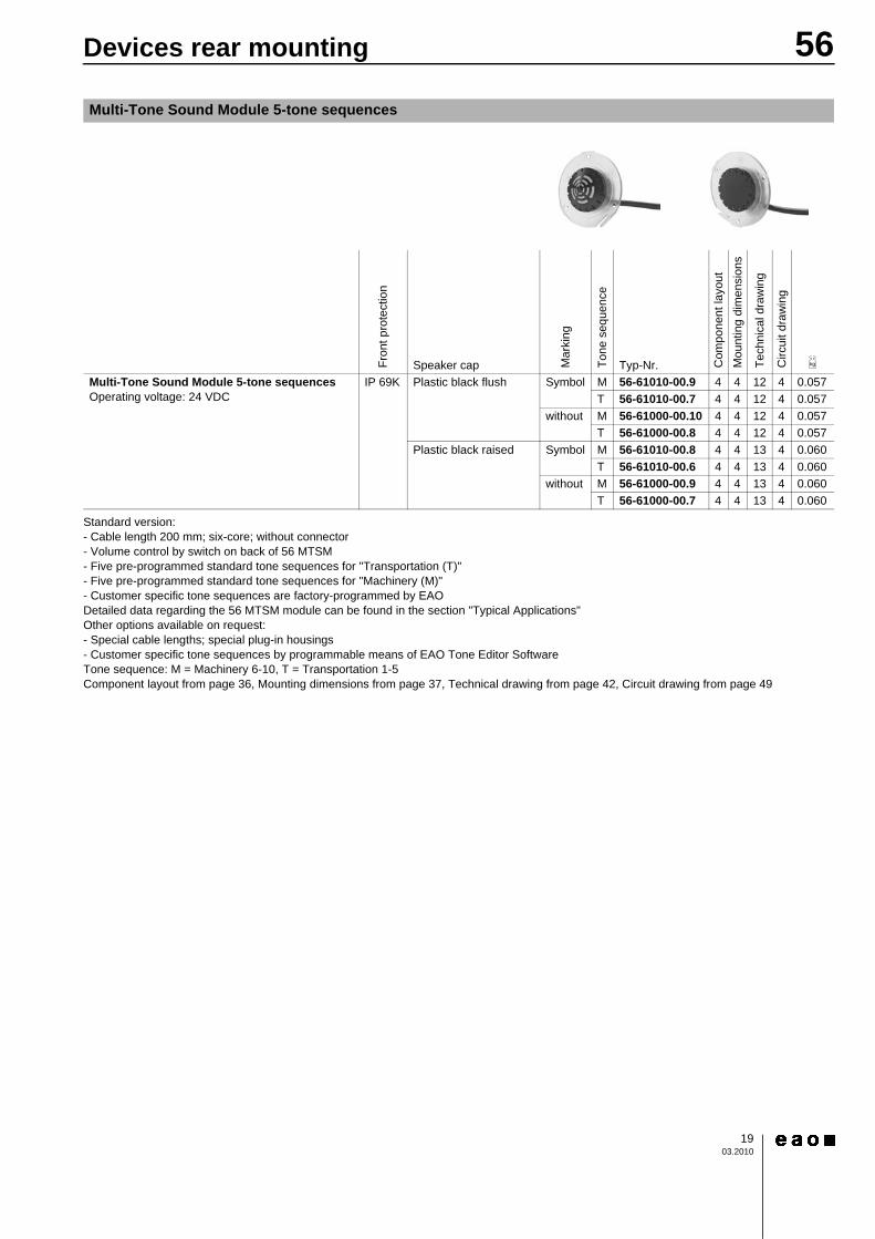
Standard version:- Cable length 200 mm; six-core; without connector- Volume control by switch on back of 56 MTSM- Five pre-programmed standard tone sequences for "Transportation (T)"- Five pre-programmed standard tone sequences for "Machinery (M)"- Customer specific tone sequences are factory-programmed by EAODetailed data regarding the 56 MTSM module can be found in the section "Typical Applications"Other options available on request:- Special cable lengths; special plug-in housings- Customer specific tone sequences by programmable means of EAO Tone Editor SoftwareTone sequence: M = Machinery 6-10, T = Transportation 1-5Component layout from page 36, Mounting dimensions from page 37, Technical drawing from page 42, Circuit drawing from page 49
Multi-Tone Sound Module 5-tone sequences
Fron
t pro
tect
ion
Speaker cap Mar
king
Tone
seq
uenc
e
Typ-Nr. Com
pone
nt la
yout
Mou
ntin
g di
men
sion
s
Tech
nica
l dra
win
g
Circ
uit d
raw
ing
e
Multi-Tone Sound Module 5-tone sequences Operating voltage: 24 VDC
IP 69K Plastic black flush Symbol M 56-61010-00.9 4 4 12 4 0.057T 56-61010-00.7 4 4 12 4 0.057
without M 56-61000-00.10 4 4 12 4 0.057T 56-61000-00.8 4 4 12 4 0.057
Plastic black raised Symbol M 56-61010-00.8 4 4 13 4 0.060T 56-61010-00.6 4 4 13 4 0.060
without M 56-61000-00.9 4 4 13 4 0.060T 56-61000-00.7 4 4 13 4 0.060

56Devices rear mounting
2003.2010
Continuation see next page
Standard version:- Cable length 200 mm; four-core; without connector- Volume control by wire of 56 MTSM- Three pre-programmed standard tone sequences for "Transportation (T1)"- Customer specific tone sequences are factory-programmed by EAO- TSI conformityDetailed data regarding the 56 MTSM module can be found in the section "Typical Applications"Other options available on request:- Special cable lengths; special plug-in housings- Operation voltage 12 VDC ±30 %- Customer specific tone sequences by programmable means of EAO Tone Editor Software- Volume Control Box availableTone sequence: T1 = Transportation 1-3Component layout from page 36, Mounting dimensions from page 37, Technical drawing from page 42, Circuit drawing from page 49
Multi-Tone Sound Module 3-tone sequences
Fron
t pro
tect
ion
Speaker cap Mar
king
Tone
seq
uenc
e
Ø 43 mmTyp-Nr. C
ompo
nent
layo
utM
ount
ing
dim
ensi
ons
Tech
nica
l dra
win
g
Circ
uit d
raw
ing
e
Multi-Tone Sound Module 3-tone sequences Operating voltage: 24 - 48 VDC
IP 40 Plastic black flush Symbol T1 56-0203.M.1210 5 4 12 5 0.057IP 69K Plastic black flush Symbol T1 56-0213.M.1211 5 4 12 5 0.057
Operating voltage: 72 - 110 VDC IP 40 Plastic black flush Symbol T1 56-0903.M.1213 5 4 12 6 0.057IP 69K Plastic black flush Symbol T1 56-0913.M.1214 5 4 12 6 0.057
56Devices glass mounting
2103.2010
Continuation see next page
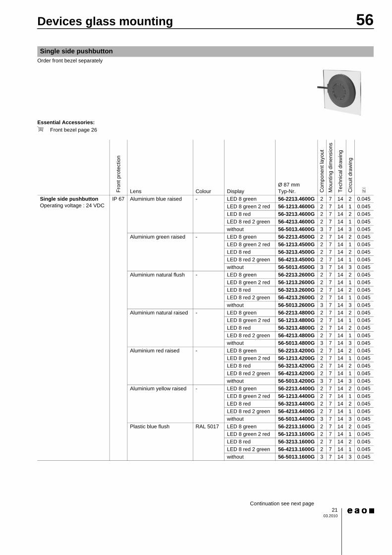
Order front bezel separately
Essential Accessories:d Front bezel page 26Continuation see next page
Single side pushbutton
Fron
t pro
tect
ion
Lens Colour DisplayØ 87 mmTyp-Nr. C
ompo
nent
layo
utM
ount
ing
dim
ensi
ons
Tech
nica
l dra
win
g
Circ
uit d
raw
ing
e
Single side pushbutton Operating voltage : 24 VDC
IP 67 Aluminium blue raised - LED 8 green 56-2213.4600G 2 7 14 2 0.045LED 8 green 2 red 56-1213.4600G 2 7 14 1 0.045LED 8 red 56-3213.4600G 2 7 14 2 0.045LED 8 red 2 green 56-4213.4600G 2 7 14 1 0.045without 56-5013.4600G 3 7 14 3 0.045
Aluminium green raised - LED 8 green 56-2213.4500G 2 7 14 2 0.045LED 8 green 2 red 56-1213.4500G 2 7 14 1 0.045LED 8 red 56-3213.4500G 2 7 14 2 0.045LED 8 red 2 green 56-4213.4500G 2 7 14 1 0.045without 56-5013.4500G 3 7 14 3 0.045
Aluminium natural flush - LED 8 green 56-2213.2600G 2 7 14 2 0.045LED 8 green 2 red 56-1213.2600G 2 7 14 1 0.045LED 8 red 56-3213.2600G 2 7 14 2 0.045LED 8 red 2 green 56-4213.2600G 2 7 14 1 0.045without 56-5013.2600G 3 7 14 3 0.045
Aluminium natural raised - LED 8 green 56-2213.4800G 2 7 14 2 0.045LED 8 green 2 red 56-1213.4800G 2 7 14 1 0.045LED 8 red 56-3213.4800G 2 7 14 2 0.045LED 8 red 2 green 56-4213.4800G 2 7 14 1 0.045without 56-5013.4800G 3 7 14 3 0.045
Aluminium red raised - LED 8 green 56-2213.4200G 2 7 14 2 0.045LED 8 green 2 red 56-1213.4200G 2 7 14 1 0.045LED 8 red 56-3213.4200G 2 7 14 2 0.045LED 8 red 2 green 56-4213.4200G 2 7 14 1 0.045without 56-5013.4200G 3 7 14 3 0.045
Aluminium yellow raised - LED 8 green 56-2213.4400G 2 7 14 2 0.045LED 8 green 2 red 56-1213.4400G 2 7 14 1 0.045LED 8 red 56-3213.4400G 2 7 14 2 0.045LED 8 red 2 green 56-4213.4400G 2 7 14 1 0.045without 56-5013.4400G 3 7 14 3 0.045
Plastic blue flush RAL 5017 LED 8 green 56-2213.1600G 2 7 14 2 0.045LED 8 green 2 red 56-1213.1600G 2 7 14 1 0.045LED 8 red 56-3213.1600G 2 7 14 2 0.045LED 8 red 2 green 56-4213.1600G 2 7 14 1 0.045without 56-5013.1600G 3 7 14 3 0.045

56Devices glass mounting
2203.2010
Continued from previous page
Standard version:- Cable length 200 mm; AMP plug-in housing 2.8 x 0.8 mmOther options available on request:- Special cable lengths; special plug-in housings- Operation voltage 36, 48, 72, 96, 110 VDC- Customer specific lens colours- Various symbolsComponent layout from page 36, Mounting dimensions from page 37, Technical drawing from page 42, Circuit drawing from page 49
Single side pushbutton Operating voltage : 24 VDC
IP 67 Plastic green flush RAL 6024 LED 8 green 56-2213.1500G 2 7 14 2 0.045LED 8 green 2 red 56-1213.1500G 2 7 14 1 0.045LED 8 red 56-3213.1500G 2 7 14 2 0.045LED 8 red 2 green 56-4213.1500G 2 7 14 1 0.045without 56-5013.1500G 3 7 14 3 0.045
Plastic red flush RAL 3020 LED 8 green 56-2213.1200G 2 7 14 2 0.045LED 8 green 2 red 56-1213.1200G 2 7 14 1 0.045LED 8 red 56-3213.1200G 2 7 14 2 0.045LED 8 red 2 green 56-4213.1200G 2 7 14 1 0.045without 56-5013.1200G 3 7 14 3 0.045
Plastic yellow flush RAL 1023 LED 8 green 56-2213.1400G 2 7 14 2 0.045LED 8 green 2 red 56-1213.1400G 2 7 14 1 0.045LED 8 red 56-3213.1400G 2 7 14 2 0.045LED 8 red 2 green 56-4213.1400G 2 7 14 1 0.045without 56-5013.1400G 3 7 14 3 0.045
Fron
t pro
tect
ion
Lens Colour DisplayØ 87 mmTyp-Nr. C
ompo
nent
layo
utM
ount
ing
dim
ensi
ons
Tech
nica
l dra
win
g
Circ
uit d
raw
ing
e

56Devices glass mounting
2303.2010
Continuation see next page
Order front bezel separately
Essential Accessories:d Front bezel page 26d Front bezel internal page 26Continuation see next page
Double side pushbutton
Fron
t pro
tect
ion
Lens Colour DisplayØ 87 mmTyp-Nr. C
ompo
nent
layo
utM
ount
ing
dim
ensi
ons
Tech
nica
l dra
win
g
Circ
uit d
raw
ing
e
Double side pushbutton Operating voltage : 24 VDC
IP 67 Aluminium blue raised - LED 16 green 56-2213.460046 2 7 15 2 0.175LED 16 green 4 red 56-1213.460046 2 7 15 1 0.175LED 16 red 56-3213.460046 2 7 15 2 0.175LED 16 red 4 green 56-4213.460046 2 7 15 1 0.175without 56-5013.460046 3 7 15 3 0.175
Aluminium green raised - LED 16 green 56-2213.450045 2 7 15 2 0.175LED 16 green 4 red 56-1213.450045 2 7 15 1 0.175LED 16 red 56-3213.450045 2 7 15 2 0.175LED 16 red 4 green 56-4213.450045 2 7 15 1 0.175without 56-5013.450045 3 7 15 3 0.175
Aluminium natural flush - LED 16 green 56-2213.260026 2 7 15 2 0.175LED 16 green 4 red 56-1213.260026 2 7 15 1 0.175LED 16 red 56-3213.260026 2 7 15 2 0.175LED 16 red 4 green 56-4213.260026 2 7 15 1 0.175without 56-5013.260026 3 7 15 3 0.175
Aluminium natural raised - LED 16 green 56-2213.480048 2 7 15 2 0.175LED 16 green 4 red 56-1213.480048 2 7 15 1 0.175LED 16 red 56-3213.480048 2 7 15 2 0.175LED 16 red 4 green 56-4213.480048 2 7 15 1 0.175without 56-5013.480048 3 7 15 3 0.175
Aluminium red raised - LED 16 green 56-2213.420042 2 7 15 2 0.175LED 16 green 4 red 56-1213.420042 2 7 15 1 0.175LED 16 red 56-3213.420042 2 7 15 2 0.175LED 16 red 4 green 56-4213.420042 2 7 15 1 0.175without 56-5013.420042 3 7 15 3 0.175
Aluminium yellow raised - LED 16 green 56-2213.440044 2 7 15 2 0.175LED 16 green 4 red 56-1213.440044 2 7 15 1 0.175LED 16 red 56-3213.440044 2 7 15 2 0.175LED 16 red 4 green 56-4213.440044 2 7 15 1 0.175without 56-5013.440044 3 7 15 3 0.175
Plastic blue flush RAL 5017 LED 16 green 56-2213.160016 2 7 15 2 0.175LED 16 green 4 red 56-1213.160016 2 7 15 1 0.175LED 16 red 56-3213.160016 2 7 15 2 0.175LED 16 red 4 green 56-4213.160016 2 7 15 1 0.175without 56-5013.160016 3 7 15 3 0.175
56Devices glass mounting
2403.2010
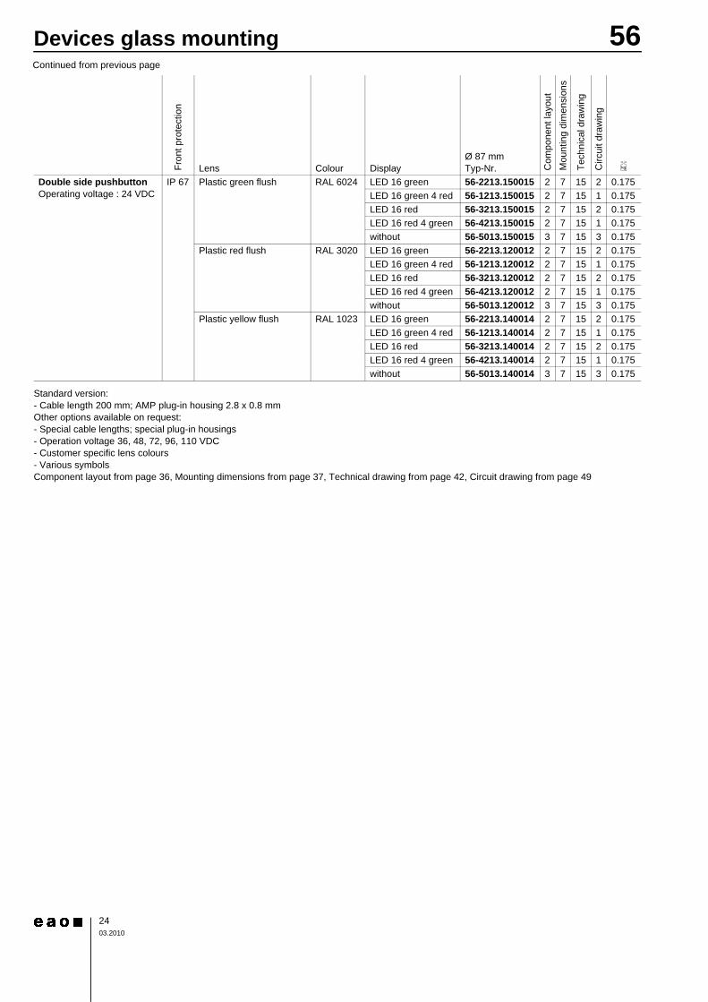
Continued from previous page
Standard version:- Cable length 200 mm; AMP plug-in housing 2.8 x 0.8 mmOther options available on request:- Special cable lengths; special plug-in housings- Operation voltage 36, 48, 72, 96, 110 VDC- Customer specific lens colours- Various symbolsComponent layout from page 36, Mounting dimensions from page 37, Technical drawing from page 42, Circuit drawing from page 49
Double side pushbutton Operating voltage : 24 VDC
IP 67 Plastic green flush RAL 6024 LED 16 green 56-2213.150015 2 7 15 2 0.175LED 16 green 4 red 56-1213.150015 2 7 15 1 0.175LED 16 red 56-3213.150015 2 7 15 2 0.175LED 16 red 4 green 56-4213.150015 2 7 15 1 0.175without 56-5013.150015 3 7 15 3 0.175
Plastic red flush RAL 3020 LED 16 green 56-2213.120012 2 7 15 2 0.175LED 16 green 4 red 56-1213.120012 2 7 15 1 0.175LED 16 red 56-3213.120012 2 7 15 2 0.175LED 16 red 4 green 56-4213.120012 2 7 15 1 0.175without 56-5013.120012 3 7 15 3 0.175
Plastic yellow flush RAL 1023 LED 16 green 56-2213.140014 2 7 15 2 0.175LED 16 green 4 red 56-1213.140014 2 7 15 1 0.175LED 16 red 56-3213.140014 2 7 15 2 0.175LED 16 red 4 green 56-4213.140014 2 7 15 1 0.175without 56-5013.140014 3 7 15 3 0.175
Fron
t pro
tect
ion
Lens Colour DisplayØ 87 mmTyp-Nr. C
ompo
nent
layo
utM
ount
ing
dim
ensi
ons
Tech
nica
l dra
win
g
Circ
uit d
raw
ing
e

56Devices glass mounting
2503.2010
Order front bezel separately
Essential Accessories:d Front bezel page 26Continuation see next page
Standard version:- Cable length 200 mm; four-core; without connector- Volume control by wire of 56 MTSM- Three pre-programmed standard tone sequences for "Transportation (T1)"- Customer specific tone sequences are factory-programmed by EAO- TSI conformityDetailed data regarding the 56 MTSM module can be found in the section "Typical Applications"Other options available on request:- Special cable lengths; special plug-in housings- Operation voltage 12 VDC ±30 %- Customer specific tone sequences by programmable means of EAO Tone Editor Software- Volume Control Box availableTone sequence: T1 = Transportation 1-3Component layout from page 36, Mounting dimensions from page 37, Technical drawing from page 42, Circuit drawing from page 49
Multi-Tone Sound Module 3-tone sequences
Fron
t pro
tect
ion
Speaker cap Mar
king
Tone
seq
uenc
e
Ø 87 mmTyp-Nr. C
ompo
nent
layo
utM
ount
ing
dim
ensi
ons
Tech
nica
l dra
win
gC
ircui
t dra
win
g
e
Multi-Tone Sound Module 3-tone sequences Operating voltage: 24 - 48 VDC
IP 69K Plastic black flush Symbol T1 56-0213.MG.1212 5 7 7 5 0.091
Operating voltage: 72 - 110 VDC IP 69K Plastic black flush Symbol T1 56-0913.MG.1215 5 7 7 6 0.091

2603.2010
56Accessories
Continuation see next page
Special colours for front bezel on request
Continuation see next page
Cable entry rightContinuation see next page
Special colours for front bezel on request
Front
Front bezel
Front bezel Colourb 87 x 87 mmTyp-Nr.
Ø 87 mmTyp-Nr. e
Front bezel For single side indicator and single side pushbutton, front mounting
Metal mat-chrome - 56-4600 0.085Plastic blue RAL 5017 56-2600 0.026Plastic green RAL 6024 56-2500 0.026Plastic red RAL 3020 56-2200 0.026Plastic yellow RAL 1023 56-2400 0.026
For single side indicator and single side pushbutton; Double side pushbutton external
Metal mat-chrome - 56-3600 0.070Plastic black RAL 9017 56-1000 0.018Plastic blue RAL 5017 56-1600 0.018Plastic dark RAL 7043 56-1800 0.018Plastic green RAL 6024 56-1500 0.018Plastic light-grey RAL 7040 56-1800A 0.018Plastic orange RAL 2003 56-1300 0.018Plastic red RAL 3020 56-1200 0.018Plastic yellow RAL 1023 56-1400 0.018
Front bezel internal
Front bezel Colour Typ-Nr. e
Front bezel internal For double side pushbutton
Metal mat-chrome - 56-7600 0.115Plastic blue RAL 5017 56-5600 0.090Plastic dark RAL 7043 56-5800 0.090Plastic green RAL 6024 56-5500 0.090Plastic light-grey RAL 7040 56-5800A 0.090Plastic orange RAL 2003 56-5300 0.090Plastic red RAL 3020 56-5200 0.090Plastic yellow RAL 1023 56-5400 0.090
Front bezel round for blind and visually impaired persons
Front bezel Colour MarkingØ 87 mmTyp-Nr. e
Front bezel round for blind and visually impaired persons For single side pushbutton; Double side pushbutton external
Plastic orange RAL 2003 Braille + Close 56-1392 0.018Braille + Open 56-1391 0.018
Plastic red RAL 3020 Braille + Open 56-1291 0.018Plastic yellow RAL 1023 Braille + Close 56-1492 0.018
Braille + Open 56-1491 0.018

2703.2010
56Accessories
Cable entry rightContinuation see next page
Special colours for front bezel on requestSOS character height 15 mm, black printed according TSI/PRM and braille SOS as per DIN 32976
>
Continuation see next page
Mounting dimensions from page 37, Technical drawing from page 42
Caution:Funnel shaped cable cover no. 992 B, C, D, E, F are not replacable after first mountingContinuation see next page
Specify Typ-Nr. in purchase orderMounting dimensions from page 37, Technical drawing from page 42
Continuation see next page
Front bezel triangular for blind and visually impaired persons
Front bezel Colour Markinga 106 x 101 mmTyp-Nr. e
Front bezel triangular for blind and visually impaired persons For single side pushbutton
Plastic yellow RAL 1023 Braille + SOS 56-8000 0.029
Assembling
Cable cover standard
Typ-Nr. Mou
ntin
g di
men
sion
sTe
chni
cal d
raw
ing
e
Cable cover standard 0°, included in standard delivery
56-992 7 1 0.003
45°, specify typ-no. in purchase order 56-992A 8 1 0.005
Cable cover funnel
Typ-Nr. Mou
ntin
g di
men
sion
sTe
chni
cal d
raw
ing
e
Cable cover funnel 0°
56-992B 5 2 0.010
10° 56-992C 6 2 0.01015° 56-992D 6 2 0.01025° 56-992E 6 2 0.0109° 56-992F 6 2 0.010
Bezel cover
Typ-Nr. e
Bezel cover 40 x 26 x 0,8 mm, adhesive, aluminium natural
56-993 0.005
2803.2010
56Accessories
Continuation see next page
For front bezelContinuation see next page
For dismounting of front bezelContinuation see next page
Continuation see next page
Continuation see next page
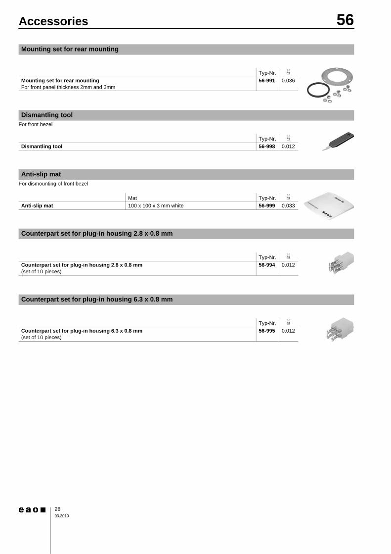
Mounting set for rear mounting
Typ-Nr. e
Mounting set for rear mounting For front panel thickness 2mm and 3mm
56-991 0.036
Dismantling tool
Typ-Nr. e
Dismantling tool 56-998 0.012
Anti-slip mat
Mat Typ-Nr. e
Anti-slip mat 100 x 100 x 3 mm white 56-999 0.033
Counterpart set for plug-in housing 2.8 x 0.8 mm
Typ-Nr. e
Counterpart set for plug-in housing 2.8 x 0.8 mm (set of 10 pieces)
56-994 0.012
Counterpart set for plug-in housing 6.3 x 0.8 mm
Typ-Nr. e
Counterpart set for plug-in housing 6.3 x 0.8 mm (set of 10 pieces)
56-995 0.012

2903.2010
56Technical Data
Switching systemSelf-cleaning, double-breaking snap-action switching system1 Normally Open contact, momentary function
Material
Connection cableHalogene free Polyolefine mixture
LensAluminium anodized or Polybutylenterephthalat (PBT), as per UL94 V0
Front bezelZinc matt chromium plated or Polybutylenterephthalat (PBT), as per UL94 V0
ActuatorPolycarbonate (PC), as per UL94 V0
Material of contactGold plated silver
Mechanical characteristics
TerminalsCable 4-poles with plug-in connection 2.8 x 0.8 mmFlat plug-in housing rectangular, AMP No. 626 057-0
Counterpart to AMP Flat plug-in housing(not part of delivery)Receptacle housing AMP No. 626 056-0Receptacle socket AMP No. 160 655-2
Other version :Cable 4 poles with plug-in connection 6.3 x 0.8 mmFlat plug-in housing rectangular, AMP No. 180 901-0
Counterpart to AMP Flat plug-in housing(not part of delivery)Receptacle housing AMP No. 180 900-0Receptacle socket AMP No. 160 860-2
Wire cross-section0.5 mm²
Wire length200 mm with AMP connector 2.8 x 0.8 mm
Fixing screwsSingle side pushbutton for front mounting M4 x 8mmDouble side pushbutton for glass mounting M4 x 25 mmSingle side pushbutton for glass mounting M4 x 20 mm (for glass ≥5 mm)Single side pushbutton for glass mounting M4 x 16 (for 4 mm glass)
Tightening torqueScrews for single side pushbutton for front mounting 80 Ncm ...100 NcmScrews for single side- and double side pushbutton for glass moun-ting 50 Ncm
Key (mounting and dismantling)Hexagon socket wrench size 2.5 mm
Actuating force6 N ... 12 N
Actuating travel~0,5 mm
Mechanical lifetime2 million cycles operation
Electrical characteristics
IlluminationReady status, 8 LED green, red or yellowOptical switch on status, 2 LED green or red (3 LED for special versions)Supply voltage 24 VDCTolerance +25 % ... -30 %Current consumption <50 mA Illuminating can vary, for production-technical reasons of the LED manufacturers, easily
EMC approved, as perEN 50081-1EN 50082-1; EN 50082-2EN 50121-3-2
Switch ratingmin. 5 VDC, 5 mAmax. 137 VDC/VAC, max. 200 mA
Electric strength4000 VAC, 50 Hz, 1 min, between all terminals and mounting plate / front element
Environmental conditions
Storage temperature-45 °C ... +90 °C
Operating temperature-40 °C ... +80 °C
Protection degreeFront side IP 67Back side IP 65
Climate resistanceDamp heat, cyclic96 hours, +25 °C / 97 %, +55 °C / 93 % relative humidity, as per EN IEC 60068-2-30 Damp heat, state56 days, +40 °C / 93 % relative humidity, as per EN IEC 60068-2-78
Rapid change of temperature100 cycles, -40 °C ... +80 °C, as per EN IEC 60068-2-14
Shock resistance(semi-sinusoidal)max. 250 m/s², pulse width 11 ms, as per EN IEC 60068-2-27
Vibration resistance(sinusoidal)max. 100 m/s² at 10 Hz ... 500 Hz, as per EN IEC 60068-2-6
Approvals
Declaration of conformityCE
Switch
3003.2010
56Technical Data>
Material
Connection cableHalogene free Polyolefine mixture
LensPolycarbonate (PC), as per UL94 V0
Front bezelZinc matt chromium plated or Polybutylenterephthalat (PBT), as per UL94 V0
ActuatorPolycarbonate (PC), as per UL94 V0
Mechanical characteristics
TerminalsCable 2-poles with plug-in connection 2.8 x 0.8 mmFlat plug-in housing rectangular, AMP No. 626 057-0
Counterpart to AMP Flat plug-in housing(not part of delivery)Receptacle housing AMP No. 626 056-0Receptacle socket AMP No. 160 655-2
Wire cross-section0.25 mm²
Wire length200 mm with AMP connector 2.8 x 0.8 mm
Fixing screwsFor front mounting M4 x 8 mm
Tightening torqueFor screws for front mounting 80 Ncm ...100 Ncm
Key (mounting and dismantling)Hexagon socket wrench size 2.5 mm
Electrical characteristics
Illumination15 LED green, red, yellow, white or blueSupply voltage 24, 110 VDCTolerance -30 % ... +25 %Current consumption <50 mA Illuminating can vary, for production-technical reasons of the LED manufacturers, easily
Approved as perIEC/EN 61000-4-6; 61000-4-3; 61000-4-4; 61000-4-2; 61000-4-5CISPR 22EN 55022
Environmental conditions
Storage temperature-45 °C ... +90 °C
Operating temperature-40 °C ... +80 °C
Protection degreeFront side IP 67Back side IP 65
Climate resistanceDamp heat, cyclic96 hours, +25 °C / 97 %, +55 °C / 93 % relative humidity, as per EN IEC 60068-2-30 Damp heat, state56 days, +40 °C / 93 % relative humidity, as per EN IEC 60068-2-78
Rapid change of temperature100 cycles, -40 °C ... +80 °C, as per EN IEC 60068-2-14
Shock resistance(semi-sinusoidal)max. 250 m/s², pulse width 11 ms, as per EN IEC 60068-2-27
Vibration resistance(sinusoidal)max. 100 m/s² at 10 Hz ... 2000 Hz, as per EN IEC 60068-2-6
Approvals
Declaration of conformityCE
>
Material
Connection cableHalogene free Polyolefine mixture
Housing switching unit and speaker capPolycarbonate (PC), as per UL94 V0
Front bezelZinc matt chromium plated or Polybutylenterephthalat (PBT), as per UL94 V0
Mechanical characteristics
Terminals200 mm with crimped metal sleeves3-tone sequences module: 4 x 0,5 mm2 or 4 x 0,25 mm2 5-tone se-quences module: 6 x 0,5 mm2
Fixing screwsFor front mounting M4 x 8mm (3x)
Tightening torqueFor screws for front mounting 80 Ncm ... 100 Ncm
Key (mounting and dismantling)Hexagon socket wrench size 2.5 mm
Electrical characteristics
StandardsThe devices comply with EN 50155
EMC approved, as perEN 50121-3-2 and EN 61000-4-4
Operating voltage/-currentOperation voltage 24, 110 VDCTolerance ±30 %Current rating <50 mA depending on voltage and volume
Indicator
Multi-Tone Sound Module

3103.2010
56Technical DataElectric strength4000 VAC, 50 Hz, 1 min, between all terminals and mounting plate / front element
Acoustic characteristicsThe tones can be played in any sequence at different volumes, durations and intervals.
5-tone sequences:The volume of each tone sequence is configured in five steps by 6 dB, adjustable from the rear side. All sounds are controlled using a wire cable.
3-tone sequences:The volume of each tone sequence can be changed in 17 steps of 1.5 dB each, by means of the tone-editing programme or "external" by wire. Tone sequence 1 and 2 are being activated by wire, whereby sequence 3 is being activated binarily. All sounds are controlled using a wire cable. In order to symplify the definition of the Multi-Tone Sound Module, a "volume control box" is at EAO customer's disposal as an accessory.
Frequency range500 Hz ... 3000 Hz ±1 %
Time range of tone sequence0 ... ∞ (endless)
Acoustic pressure level90 dB ±8 dB @ 0.1 m @ 1 kHzLevel 17 for 3-tone sequences moduleLevel 5 for 5-tone sequences module
One tone sequence consists ofTwo frequences at any duration and any repeat stepsMulti-tone programmable according to TSI/PRM
Environmental conditions
Storage temperature-45 °C ... +90 °C
Operating temperature-40 °C ... +85 °C
Protection degree3-tone sequences module: Front side IP 69K oder IP 40; Rear side IP 655-tone sequences module: Front side IP 69K; Rear side IP 65
Climate resistanceDamp heat, cyclic48 hours, +25 °C / 97 %, +55 °C / 93 % relative humidity, as per EN IEC 60068-2-30
Saline mist 96 hours, as per EN IEC 60068-2-11
Shock resistance(semi-sinusoidal)max. 50 m/s², pulse width 30 ms, as per EN 61373
Vibration resistanceMax. 7.9 m/s² at 10 Hz ... 150 Hz, as per EN 61373
Approvals
Declaration of conformityCEe1E1TSI/PRM

56Typical Applications
3203.2010
0
0
>
0
>
Multi-Tone Sound Module, standard tone sequence
F1 Frequency 1 of a tone sequenceT2 Playing time tone 1T4 BreakN Number of repetitions of tone 1F2 Frequency 2 of a tone sequenceT5 Playing time tone 2T6 BreakM Number of repetitions of tone 2A Volume level (±8 dB) @ 10 cm @ 1 kHzB Number of repetitions of the complete tone sequence, or blockage of the tone sequenceT1 Fade-in tone 1 and 2T3 Fade-out tone 1 and 2
Tone sequences 1-5 Transportation (T)
Parameter Sequence 1Door orientation signal
Sequence 2Door opening signal
Sequence 3Warning signal for door closing
Sequence 4Door out of order signal
Sequence 5Hussle Alarm
Tone 1 F1 500 Hz 800 Hz 2000 Hz 1400 Hz 875 HzT2 500 ms 300 ms 500 ms 50 ms 1000 msT4 900 ms 700 ms 200 ms 100 ms 250 msN ∞ ∞ ∞ 3 3
Tone 2 F2 deactivated 830 Hz deactivated deactivated deactivatedT5 deactivated 500 ms deactivated deactivated deactivatedT6 deactivated 0 ms deactivated deactivated deactivatedM deactivated 1 deactivated deactivated deactivated
General A 3 / 78 dB 3 / 78 dB 5 / 90 dB 3 / 78 dB 3 / 78 dBB ∞ ∞ 1 1 1T1 0 ms 0 ms 0 ms 0 ms 0 msT3 0 ms 0 ms 0 ms 0 ms 0 ms
F1 F2
T6T3T5T1T4T3T2T1
A
N M
B
Volu
me
Time

56Typical Applications
3303.2010
0
>
0
Tone sequences 1-3 Transportation (T1)
Parameter Sequence 1Door enabled
Sequence 2Door closing
Sequence 3Signal for visual impaired people
Tone 1 F1 1500 Hz 1900 Hz 600 HzT2 ∞ 50 ms 50 msT4 250 ms 50 ms 20 msN ∞ ∞ ∞
Tone 2 F2 deactivated deactivated 500 HzT5 deactivated deactivated 1000 msT6 deactivated deactivated 900 msM deactivated deactivated 1
General A 17 / 90 dB 17 / 90 dB 9 / 78 dBB ∞ ∞ ∞
T1 0 ms 0 ms 0 msT3 0 ms 0 ms 0 ms
Tone sequences 6-10 Machinery (M)
Parameter Sequence 6 Sequence 7 Sequence 8 Sequence 9 Sequence 10Tone 1 F1 750 HZ 2500 Hz 2000 Hz 2500 Hz 1000 Hz
T2 100 ms 300 ms 250 ms 100 ms 500 msT4 200 ms 500 ms 200 ms 100 ms 100 msN 1 1 1 2 1
Tone 2 F2 500 Hz 2000 Hz 1000 Hz 2000 Hz 1500 HzT5 450 ms 500 ms 250 ms 100 ms 500 msT6 100 ms 400 ms 200 ms 100 ms 100 msM 1 1 1 2 1
General A 4 / 84 dB 4 / 84 dB 5 / 90 dB 5 / 90 dB 4 / 84 dBB ∞ ∞ ∞ ∞ ∞
T1 0 ms 0 ms 0 ms 0 ms 0 msT3 200 ms 0 ms 500 ms 0 ms 0 ms

56Application guidelines
3403.2010
When switching inductive loads such as relays, DC motors, and DC solenoids, it is always importantto absorb surges (e.g. with a diode) to protect the contacts. When these inductive loads are switchedoff, a counter emf can severely damage switch contacts and greatly shorten lifetime.
Fig. 1 shows an inductive load with a free-wheeling diode connected in parallel. This free-wheelingdiode provides a path for the inductor current to flow when the current is interrupted by the switch.Without this free-wheeling diode, the voltage across the coil will be limited only by dielectric break-down voltages of the circuit or parasitic elements of the coil. This voltage can be kilovolts in amplitudeeven when nominal circuit voltages are low (e.g. 12 VDC) see Fig. 2.
The free-wheeling diode should be chosen so that the reverse breakdown voltage is greater than thevoltage driving the inductive load. The DC blocking voltage (VR) of the free-wheeling diode can befound in the datasheet of a diode. The forward current should be equal or greater than the maximumcurrent flowing through the load.
To get an efficient protection, the free-wheeling diode must be connected as close as possibleto the inductive load!
0
Suppressor circuits
Sveral hundred
to several
thousend volts
ON OFF
0
e = Ldi
dt__
VDC
Switch
Free-wheeling
diode
Inductive
load
Counter emf
over load without free-wheeling diode
Fig. 2
Switching with inductive load
Fig. 1
+_

56Marking
3503.2010
Symbol colour : black0
0
Specified symbols and text on 1...3 lines on requestNote:For marking, please indicate the cable entry is left or right (left or right as seen from outside).Symbol-No. 00.868 and 00.869 are also available in raised, tangibel version.
Marking of lens
Marking Symbol no.Baby carriage 60523Wheelchair 40089Door open 00.835Door open 00.868Door close 00.869Door close 00.836
00.868 00.869 00.835 00.836 60523 40089
56Drawings
3603.2010
1 Single side indicator page 7 | Single side indicator raised conical page 8 | Single side indicator page 15 | Single side indicator raised conical page 16
2 Single side pushbutton page 9 | Single side pushbutton page 17 | Single side pushbutton page 21 | Double side pushbutton page 23
3 Single side pushbutton page 9 | Single side pushbutton page 17 | Single side pushbutton page 21 | Double side pushbutton page 23
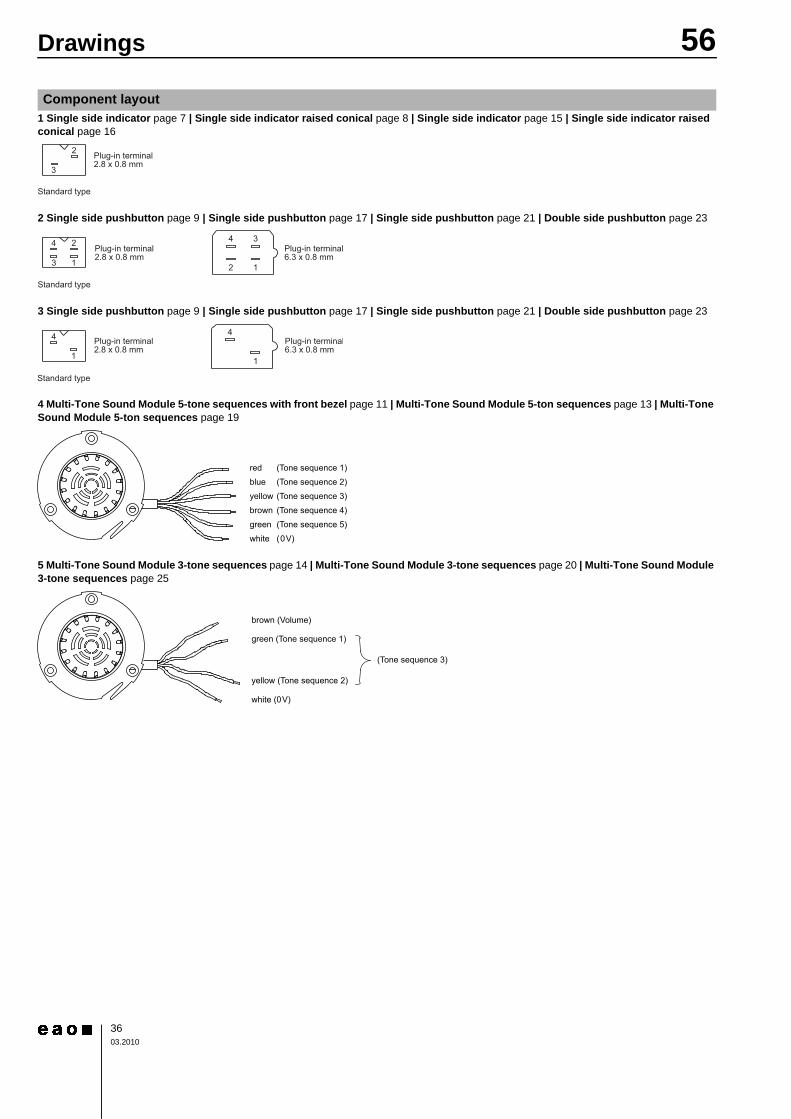
4 Multi-Tone Sound Module 5-tone sequences with front bezel page 11 | Multi-Tone Sound Module 5-ton sequences page 13 | Multi-Tone Sound Module 5-ton sequences page 19
5 Multi-Tone Sound Module 3-tone sequences page 14 | Multi-Tone Sound Module 3-tone sequences page 20 | Multi-Tone Sound Module 3-tone sequences page 25
Component layout
Plug-in terminal2.8 x 0.8 mm
3
2
Standard type
4
3 1
4 2
2 1
3
Plug-in terminal2.8 x 0.8 mm
Plug-in terminal6.3 x 0.8 mm
Standard type
red
blue
yellow
brown
green
white
(Tone sequence 1)
(Tone sequence 2)
(Tone sequence 3)
(Tone sequence 4)
(Tone sequence 5)
(0V)
brown (Volume)
green (Tone sequence 1)
(Tone sequence 3)
yellow (Tone sequence 2)
white (0V)

56Drawings
3703.2010
1 Single side pushbutton page 17
2 Single side pushbutton page 9
Mounting dimensions
43
76 min.
76 m
in.
3 x M4 Studs
18 min. 43.1+0.3 0
65
4 max.
A Cable right side
B Cable left side
A
A
Cable
B
B
Front bezel round
88 min.
Fro
nt bezel ro
und
88 m
in.
3 x M4 Tap hole
42+1.4 0 8787
Front bezel square
112 min.
87
Fro
nt bezel square
11
2 m
in.
65
Cable
A
B
B
A
A Cable right side
B Cable left side
5 max.

56Drawings
3803.2010
3 Single side indicator page 7 | Single side indicator raised conical page 8 | Multi-Tone Sound Module 5-tone sequences with front bezel page 11 | Multi-Tone Sound Module 5-ton sequences page 13 | Multi-Tone Sound Module 3-tone sequences page 14
4 Single side indicator page 15 | Single side indicator raised conical page 16 | Multi-Tone Sound Module 5-ton sequences page 19 | Multi-Tone Sound Module 3-tone sequences page 20
5 max.
A Cable right side
B Cable left side
Fro
nt bezel ro
und
88 m
in.
8787
Front bezel square
112 min.
87
Fro
nt bezel square
11
2 m
in.
3 x M4 Tap hole
Cable
A
B
B
A
Front bezel round
88 min.
42+1.4 0
65
43
76 min.
76 m
in.
3 x M4 Studs
43.1+0.3 0
65
A Cable right side
B Cable left sid
B
A
A
Cable
B
18 min.
3 max.
56Drawings
3903.2010
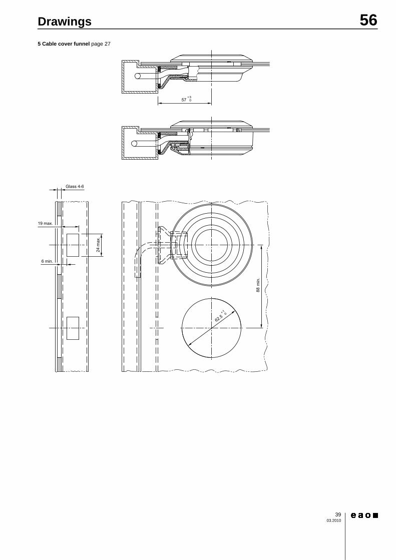
5 Cable cover funnel page 27
56Drawings
4003.2010
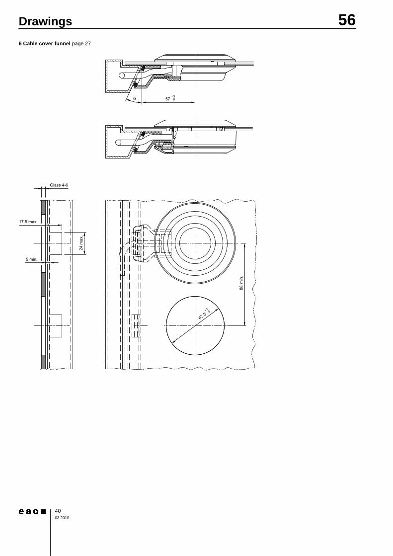
6 Cable cover funnel page 27

56Drawings
4103.2010
7 Single side pushbutton page 21 | Double side pushbutton page 23 | Multi-Tone Sound Module 3-tone sequences page 25 | Cable cover standard page 27

56Drawings
4203.2010
8 Cable cover standard page 27
1 Cable cover standard page 27
Technical drawing

56Drawings
4303.2010
2 Cable cover funnel page 27
3 Single side pushbutton page 17
4 Single side pushbutton page 9
56Drawings
4403.2010
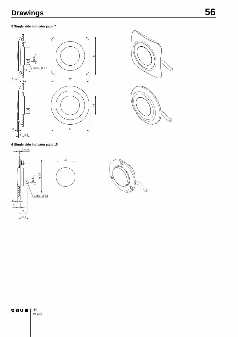
5 Single side indicator page 7
6 Single side indicator page 15

56Drawings
4503.2010
7 Multi-Tone Sound Module 3-tone sequences page 25
8 Single side indicator raised conical page 8
Glass 4-6
8
87
16.5
Cable Ø5.8
Cable cover
moveavble
43 35
12.5
5 max.
10
17.5
13
8
87
87
OO 5.8Cable
87
43
56Drawings
4603.2010
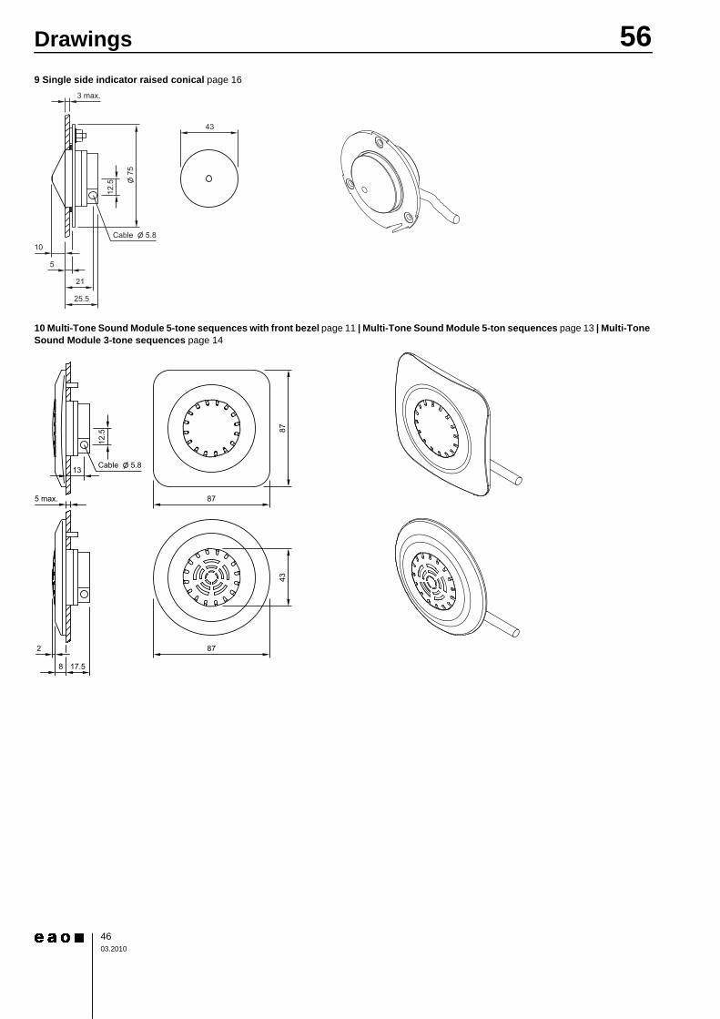
9 Single side indicator raised conical page 16
10 Multi-Tone Sound Module 5-tone sequences with front bezel page 11 | Multi-Tone Sound Module 5-ton sequences page 13 | Multi-Tone Sound Module 3-tone sequences page 14
OO
12.5
21
5
3 max.
43
25.5
10
OO 5.8Cable
75
87
87
OO 5.8
12.5
13
5 max.
2
8 17.5
Cable
43
87

56Drawings
4703.2010
11 Multi-Tone Sound Module 5-tone sequences with front bezel page 11 | Multi-Tone Sound Module 5-ton sequences page 13
12 Multi-Tone Sound Module 5-ton sequences page 19 | Multi-Tone Sound Module 3-tone sequences page 20
12.5
5 max.
10
17.5
13
8
87
87
OO 5.8Cable
87
43
3 max.
OO 5.8
OO75
12.5
21
5
43
25.5
2
Cable

56Drawings
4803.2010
13 Multi-Tone Sound Module 5-ton sequences page 19
14 Single side pushbutton page 21
15 Double side pushbutton page 23
OO
12.5
21
5
3 max.
43
25.5
10
OO 5.8Cable
75

56Drawings
4903.2010
1 Single side pushbutton page 9 | Single side pushbutton page 17 | Single side pushbutton page 21 | Double side pushbutton page 23
2 Single side pushbutton page 9 | Single side pushbutton page 17 | Single side pushbutton page 21 | Double side pushbutton page 23
3 Single side pushbutton page 9 | Single side pushbutton page 17 | Single side pushbutton page 21 | Double side pushbutton page 23
4 Multi-Tone Sound Module 5-tone sequences with front bezel page 11 | Multi-Tone Sound Module 5-ton sequences page 13 | Multi-Tone Sound Module 5-ton sequences page 19
5 Multi-Tone Sound Module 3-tone sequences page 14 | Multi-Tone Sound Module 3-tone sequences page 20 | Multi-Tone Sound Module 3-tone sequences page 25
6 Multi-Tone Sound Module 3-tone sequences page 14 | Multi-Tone Sound Module 3-tone sequences page 20 | Multi-Tone Sound Module 3-tone sequences page 25
Circuit drawing
max.137 VDC200 mA
+ VDC
0 V
1 ye
2 bn
4 gn
3 wh
1 x 8 LEDs
2 x 8 LEDs
Single side pushbutton
Double side pushbutton
1 x 2 LEDs
2 x 2 LEDs
Single side pushbutton
Double side pushbutton
+24VDC
red
blue
yellow
brown
green
white
Tone 1
Tone 2
Tone 3
Volu
me
Tone 4
Tone 5
0 V
+24VDC
brown
green
yellow
white
Volume
0V
green
yellow
24V
0V
0V
24V
Tone sequence
1Wire 2
24V
24V
3
+110VDC
brown
green
yellow
white
Volume
0V
green
yellow
110V
0V
0V
110V
Tone sequence
1Wire 2
110V
110V
3

56Drawings
5003.2010
7 Single side indicator page 7 | Single side indicator raised conical page 8 | Single side indicator page 15 | Single side indicator raised conical page 16

Index from Typ-Nr.
5103.2010
Typ-Nr. Page Typ-Nr. Page Typ-Nr. Page
56-010.04.200.00.01 .................. 1056-010.04.200.00.01 .................. 1856-010.04.200.00.02 .................. 1056-010.04.200.00.02 .................. 1856-010.04.200.00.03 .................. 1056-010.04.200.00.03 .................. 1856-010.04.200.00.04 .................. 1056-010.04.200.00.04 .................. 1856-020.04.200.00.05 .................. 1756-020.04.200.00.05 .................... 956-0203.M.1210 ......................... 1456-0203.M.1210 ......................... 2056-0213.M.1211 ......................... 1456-0213.M.1211 ......................... 2056-0213.MG.1212 ...................... 2556-030.04.200.00.01 .................. 1756-030.04.200.00.01 .................... 956-030.04.200.00.02 .................. 1756-030.04.200.00.02 .................... 956-030.04.200.00.03 .................. 1756-030.04.200.00.03 .................... 956-030.04.200.00.04 .................. 1756-030.04.200.00.04 .................... 956-030.04.200.00.05 .................. 1756-030.04.200.00.05 .................... 956-0903.M.1213 ......................... 1456-0903.M.1213 ......................... 2056-0913.M.1214 ......................... 1456-0913.M.1214 ......................... 2056-0913.MG.1215 ...................... 2556-1000 ...................................... 2656-110.22.200.21.01 .................. 1056-110.22.200.21.01 .................. 1856-110.22.200.21.02 .................. 1056-110.22.200.21.02 .................. 1856-110.22.200.21.03 .................. 1056-110.22.200.21.03 .................. 1856-110.22.200.21.04 .................. 1056-110.22.200.21.04 .................. 1856-110.22.200.22.01 .................. 1056-110.22.200.22.01 .................. 1856-110.22.200.22.02 .................. 1056-110.22.200.22.02 .................. 1856-110.22.200.22.03 .................. 1056-110.22.200.22.03 .................. 1856-110.22.200.22.04 .................. 1056-110.22.200.22.04 .................. 1856-110.22.200.23.01 .................. 1056-110.22.200.23.01 .................. 1856-110.22.200.23.02 .................. 1056-110.22.200.23.02 .................. 1856-110.22.200.23.03 .................. 1056-110.22.200.23.03 .................. 1856-110.22.200.23.04 .................. 1056-110.22.200.23.04 .................. 1856-110.22.200.24.01 .................. 1056-110.22.200.24.01 .................. 1856-110.22.200.24.02 .................. 1056-110.22.200.24.02 .................. 1856-110.22.200.24.03 .................. 1056-110.22.200.24.03 .................. 1856-110.22.200.24.04 .................. 1056-110.22.200.24.04 .................. 18
56-110.22.200.25.01 ..................1056-110.22.200.25.01 ..................1856-110.22.200.25.02 ..................1056-110.22.200.25.02 ..................1856-110.22.200.25.03 ..................1056-110.22.200.25.03 ..................1856-110.22.200.25.04 ..................1056-110.22.200.25.04 ..................1856-120.22.200.21.05 ..................1756-120.22.200.21.05 .................... 956-120.22.200.22.05 ..................1756-120.22.200.22.05 .................... 956-120.22.200.23.05 ..................1756-120.22.200.23.05 .................... 956-120.22.200.24.05 ..................1756-120.22.200.24.05 .................... 956-120.22.200.25.05 ..................1756-120.22.200.25.05 .................... 956-1200 ......................................2656-1213.120012 .........................2456-1213.1200G .......................... 2256-1213.140014 .........................2456-1213.1400G .......................... 2256-1213.150015 .........................2456-1213.1500G .......................... 2256-1213.160016 .........................2356-1213.1600G .......................... 2156-1213.260026 .........................2356-1213.2600G .......................... 2156-1213.420042 .........................2356-1213.4200G .......................... 2156-1213.440044 .........................2356-1213.4400G .......................... 2156-1213.450045 .........................2356-1213.4500G .......................... 2156-1213.460046 .........................2356-1213.4600G .......................... 2156-1213.480048 .........................2356-1213.4800G .......................... 2156-1291 ......................................2656-130.22.200.21.01 ..................1756-130.22.200.21.01 .................... 956-130.22.200.21.02 ..................1756-130.22.200.21.02 .................... 956-130.22.200.21.03 ..................1756-130.22.200.21.03 .................... 956-130.22.200.21.04 ..................1756-130.22.200.21.04 .................... 956-130.22.200.21.05 ..................1756-130.22.200.21.05 .................... 956-130.22.200.22.01 ..................1756-130.22.200.22.01 .................... 956-130.22.200.22.02 ..................1756-130.22.200.22.02 .................... 956-130.22.200.22.03 ..................1756-130.22.200.22.03 .................... 956-130.22.200.22.04 ..................1756-130.22.200.22.04 .................... 956-130.22.200.22.05 ..................1756-130.22.200.22.05 .................... 956-130.22.200.23.01 ..................1756-130.22.200.23.01 .................... 956-130.22.200.23.02 ..................17
56-130.22.200.23.02 ....................956-130.22.200.23.03 ..................1756-130.22.200.23.03 ....................956-130.22.200.23.04 ..................1756-130.22.200.23.04 ....................956-130.22.200.23.05 ..................1756-130.22.200.23.05 ....................956-130.22.200.24.01 ..................1756-130.22.200.24.01 ....................956-130.22.200.24.02 ..................1756-130.22.200.24.02 ....................956-130.22.200.24.03 ..................1756-130.22.200.24.03 ....................956-130.22.200.24.04 ..................1756-130.22.200.24.04 ....................956-130.22.200.24.05 ..................1756-130.22.200.24.05 ....................956-130.22.200.25.01 ..................1756-130.22.200.25.01 ....................956-130.22.200.25.02 ..................1756-130.22.200.25.02 ....................956-130.22.200.25.03 ..................1756-130.22.200.25.03 ....................956-130.22.200.25.04 ..................1756-130.22.200.25.04 ....................956-130.22.200.25.05 ..................1756-130.22.200.25.05 ....................956-1300 ......................................2656-1391 ......................................2656-1392 ......................................2656-1400 ......................................2656-1491 ......................................2656-1492 ......................................2656-1500 ......................................2656-1600 ......................................2656-1800 ......................................2656-1800A ....................................2656-2200 ......................................2656-2213.120012 .........................2456-2213.1200G ..........................2256-2213.140014 .........................2456-2213.1400G ..........................2256-2213.150015 .........................2456-2213.1500G ..........................2256-2213.160016 .........................2356-2213.1600G ..........................2156-2213.260026 .........................2356-2213.2600G ..........................2156-2213.420042 .........................2356-2213.4200G ..........................2156-2213.440044 .........................2356-2213.4400G ..........................2156-2213.450045 .........................2356-2213.4500G ..........................2156-2213.460046 .........................2356-2213.4600G ..........................2156-2213.480048 .........................2356-2213.4800G ..........................2156-2213.70 .................................1656-2213.70 ...................................856-2213.8 ...................................1556-2213.8 .....................................756-2213.90 .................................15

Index from Typ-Nr.
5203.2010
Typ-Nr. Page Typ-Nr. Page Typ-Nr. Page
56-2213.90 ...................................756-2213.91 .................................1556-2213.91 ...................................756-2213.92 .................................1556-2213.92 ...................................756-2213.93 .................................1556-2213.93 ...................................756-2400 ......................................2656-2500 ......................................2656-2600 ......................................2656-2913.70 .................................1656-2913.70 ...................................856-3213.120012 .........................2456-3213.1200G ..........................2256-3213.140014 .........................2456-3213.1400G ..........................2256-3213.150015 .........................2456-3213.1500G ..........................2256-3213.160016 .........................2356-3213.1600G ..........................2156-3213.260026 .........................2356-3213.2600G ..........................2156-3213.420042 .........................2356-3213.4200G ..........................2156-3213.440044 .........................2356-3213.4400G ..........................2156-3213.450045 .........................2356-3213.4500G ..........................2156-3213.460046 .........................2356-3213.4600G ..........................2156-3213.480048 .........................2356-3213.4800G ..........................2156-3213.70 .................................1656-3213.70 ...................................856-3213.8 ...................................1556-3213.8 .....................................756-3213.90 .................................1556-3213.90 ...................................756-3213.91 .................................1556-3213.91 ...................................756-3213.92 .................................1556-3213.92 ...................................756-3213.93 .................................1556-3213.93 ...................................756-3600 ......................................2656-3913.70 .................................1656-3913.70 ...................................856-4213.120012 .........................2456-4213.1200G ..........................2256-4213.140014 .........................2456-4213.1400G ..........................2256-4213.150015 .........................2456-4213.1500G ..........................2256-4213.160016 .........................2356-4213.1600G ..........................2156-4213.260026 .........................2356-4213.2600G ..........................2156-4213.420042 .........................2356-4213.4200G ..........................2156-4213.440044 .........................2356-4213.4400G ..........................2156-4213.450045 .........................2356-4213.4500G ..........................21
56-4213.460046 .........................2356-4213.4600G ..........................2156-4213.480048 .........................2356-4213.4800G ..........................2156-4213.70 .................................1656-4213.70 ...................................856-4600 ......................................2656-4913.70 .................................1656-4913.70 ...................................856-5013.120012 .........................2456-5013.1200G ..........................2256-5013.140014 .........................2456-5013.1400G ..........................2256-5013.150015 .........................2456-5013.1500G ..........................2256-5013.160016 .........................2356-5013.1600G ..........................2156-5013.260026 .........................2356-5013.2600G ..........................2156-5013.420042 .........................2356-5013.4200G ..........................2156-5013.440044 .........................2356-5013.4400G ..........................2156-5013.450045 .........................2356-5013.4500G ..........................2156-5013.460046 .........................2356-5013.4600G ..........................2156-5013.480048 .........................2356-5013.4800G ..........................2156-5200 ......................................2656-5300 ......................................2656-5400 ......................................2656-5500 ......................................2656-5600 ......................................2656-5800 ......................................2656-5800A ....................................2656-61000-00.10 ..........................1356-61000-00.10 ..........................1956-61000-00.7 ............................1356-61000-00.7 ............................1956-61000-00.8 ............................1356-61000-00.8 ............................1956-61000-00.9 ............................1356-61000-00.9 ............................1956-61001-00.10 ..........................1156-61001-00.11 ..........................1156-61001-00.12 ..........................1256-61001-00.13 ..........................1156-61001-00.14 ..........................1256-61001-00.15 ..........................1156-61001-00.16 ..........................1256-61001-00.17 ..........................1156-61001-00.18 ..........................1156-61001-00.19 ..........................1256-61001-00.2 ............................1156-61001-00.20 ..........................1156-61001-00.21 ..........................1256-61001-00.22 ..........................1156-61001-00.23 ..........................1256-61001-00.24 ..........................1156-61001-00.25 ..........................1156-61001-00.3 ............................1156-61001-00.4 ............................11
56-61001-00.5 ............................1156-61001-00.6 ............................1156-61001-00.7 ............................1156-61001-00.8 ............................1156-61001-00.9 ............................1156-61010-00.6 ............................1356-61010-00.6 ............................1956-61010-00.7 ............................1356-61010-00.7 ............................1956-61010-00.8 ............................1356-61010-00.8 ............................1956-61010-00.9 ............................1356-61010-00.9 ............................1956-61011-00.10 ..........................1156-61011-00.11 ..........................1156-61011-00.12 ..........................1156-61011-00.13 ..........................1256-61011-00.14 ..........................1156-61011-00.15 ..........................1256-61011-00.16 ..........................1156-61011-00.17 ..........................1256-61011-00.18 ..........................1156-61011-00.19 ..........................1156-61011-00.20 ..........................1256-61011-00.21 ..........................1156-61011-00.22 ..........................1256-61011-00.23 ..........................1156-61011-00.24 ..........................1256-61011-00.25 ..........................1156-61011-00.26 ..........................1156-61011-00.3 ............................1156-61011-00.4 ............................1156-61011-00.5 ............................1156-61011-00.6 ............................1156-61011-00.7 ............................1156-61011-00.8 ............................1156-61011-00.9 ............................1156-6213.70 .................................1656-6213.70 ...................................856-6213.8 ...................................1556-6213.8 .....................................756-6213.90 .................................1556-6213.90 ...................................756-6213.91 .................................1556-6213.91 ...................................756-6213.92 .................................1556-6213.92 ...................................756-6213.93 .................................1556-6213.93 ...................................756-6913.70 .................................1656-6913.70 ...................................856-7600 ......................................2656-8000 ......................................2756-8213.70 .................................1656-8213.70 ...................................856-8213.8 ...................................1556-8213.8 .....................................756-8213.90 .................................1556-8213.90 ...................................756-8213.91 .................................1556-8213.91 ...................................756-8213.92 .................................1556-8213.92 ...................................7

Index from Typ-Nr.
5303.2010
Typ-Nr. Page Typ-Nr. Page Typ-Nr. Page
56-8213.93 ................................. 1556-8213.93 ................................... 756-8913.70 ................................. 1656-8913.70 ................................... 856-9213.70 ................................. 1656-9213.70 ................................... 856-9213.8 ................................... 1556-9213.8 ..................................... 756-991 ........................................ 2856-9913.70 ................................. 1656-9913.70 ................................... 856-992 ........................................ 2756-992A ..................................... 2756-992B ..................................... 2756-992C ..................................... 2756-992D ..................................... 2756-992E ..................................... 2756-992F ...................................... 2756-993 ........................................ 2756-994 ........................................ 2856-995 ........................................ 2856-998 ........................................ 2856-999 ........................................ 28

EAO AG Tannwaldstrasse 88 4601 Olten, Switzerland E-mail [email protected] Website www.eao.com Austria Phone +49 201 85 87 0 Fax +49 201 85 87 210 E-mail [email protected] Belgium Phone +32 3 777 82 36 Fax +32 3 777 84 19 E-mail [email protected] China Phone +852 27 86 91 41 Fax +852 27 86 95 61 E-mail [email protected] France Phone +33 1 64 43 37 37 Fax +33 1 64 43 37 49 E-mail [email protected] Germany Phone +49 201 85 87 0 Fax +49 201 85 87 210 E-mail [email protected] Italy Phone +39 035 481 0189 Fax +39 035 481 3786 E-mail [email protected] Japan Phone +81 3 5444 5411 Fax +81 3 5444 0345 E-mail [email protected] Netherlands Phone +31 78 653 17 00 Fax +31 78 653 17 99 E-mail [email protected] Sweden Phone +46 8 683 86 60 Fax +46 8 724 29 12 E-mail [email protected] Switzerland Phone +41 62 388 95 00 Fax +41 62 388 95 55 E-mail [email protected] United Kingdom Phone +44 1444 236 000 Fax +44 1444 236 641 E-mail [email protected] USA Phone +1 203 877 4577 Fax +1 203 877 3694 E-mail [email protected] Other Countries Phone +41 62 286 92 10 Fax +41 62 296 21 62 E-mail [email protected]
EA
O re
serv
es th
e rig
ht to
alte
r sp
ecifi
catio
ns w
ithou
t fur
ther
not
ice