eagle® e and f - federal signal corporation series-f... · eagle® series e and f operators manual...
TRANSCRIPT

E a g l e ® E a n d F
OPERATORS MANUAL


EAGLE® SERIES E and F
OPERATORS MANUAL
Sweeper Serial Number_____________________________
Elgin Sweeper CompanySubsidiary of Federal Signal Corporation1300 W. Bartlett Road, Elgin, IL 60120
Phone 847/741-5370FAX 847/742-3035
P/N 0701480-D

Printed in U.S.A. Copyright 2007 Elgin Sweeper Company

Welcome to the World’s Most Popular Four-Wheel Broom Sweeper -
The Elgin Eagle® Series E and F
i
Read this manual carefully and completely before oper-ating the sweeper. Working with unfamiliar equipmentcan lead to accidents. Understand and follow all safetyinformation when operating the sweeper.
Elgin employees carefully inspected the sweeper beforeit left the factory. Your Elgin equipment dealer inspect-ed the sweeper and made certain that it was in properworking order prior to delivery.
To keep the Eagle sweeper in good working condition, itis important to follow all maintenance and serviceschedules, including
DAILY SERVICE - After every shift or 10 hoursPERIODIC SERVICE - After each period of 50, 150,
500 or 1000 hours
Refer to the maintenance schedule in the MaintenanceSection. This schedule is also displayed on the fueltank.
Keep this manual in the cab of the sweeper for refer-ence. If a problem develops with the sweeper, yourElgin Dealer has the factory-trained service personnel,genuine Elgin parts and necessary tools and equipmentto meet your specific needs.
If you should need to contact the factory regardingoperation, maintenance or repair, please feel free to callElgin at 847/741-5370.
This manual will assist in the proper operation and care of the Elgin Eagle Series E and F Sweeper. It containsspecific information on features and specifications, suggested operating techniques, preventive maintenance hints
and instructions for making repairs and adjustments.

ii

LIMITED WARRANTY
ELGIN SWEEPER COMPANY warrants each new machine manufactured by itagainst defects in material and workmanship provided the machine is used in anormal and reasonable manner. This warranty is extended only to the originaluser-purchaser for a period of twelve (12) months from the date of delivery to theoriginal user-purchaser.
ELGIN SWEEPER COMPANY will cause to be repaired or replaced, as the Company may elect, any part or parts of suchmachine which the Company’s examination discloses to be defective in material or workmanship.
Repairs or replacements are to be made at the selling Elgin distributor’s location or at other locations approved by ELGINSWEEPER COMPANY.
The ELGIN SWEEPER COMPANY warranty shall not apply to:1. Major components or trade accessories such as trucks, engines, tires or batteries that have a separate warranty by the origi-
nal manufacturer.
2. Normal adjustments and maintenance services.
3. Normal wear parts such as broom filters, broom wire, shoe runners and rubber deflector.
4. Failures resulting from the machine being operated in a manner or for a purpose not recommended by ELGIN SWEEPERCOMPANY.
5. Repairs, modifications or alterations which, in the Company’s sole judgment, have adversely affected the machine’s stabilityor reliability.
6. Items subjected to misuse, negligence, accident or improper maintenance.
iii

The use in the product of any part other than parts approved by ELGIN SWEEPER COMPANY may invalidate this warranty.ELGIN SWEEPER COMPANY reserves the right to determine, in its sole discretion, if the use of non-approved parts operatesto invalidate the warranty.
Nothing contained in this warrant shall make ELGIN SWEEPER COMPANY liable for loss, injury or damage of any kind toany person or entity resulting from any defect or failure in the machine.
TO THE EXTENT LIMITED BY LAW, THIS WARRANTY IS IN LIEU OF ALL OTHER WARRANTIES, EXPRESS ORIMPLIED, INCLUDING WITHOUT LIMITATION, ANY IMPLIED WARRANTIES OF MERCHANTABILITY AND FITNESSFOR A PARTICULAR PURPOSE.
This warranty is also in lieu of all other obligations or liabilities on the part of ELGIN SWEEPER COMPANY, including but notlimited to, liability for incidental and consequential damages on the part of the Company or the seller.
ELGIN SWEEPER COMPANY makes no representation that the machine has the capacity to perform any functions other thanas contained in the Company’s written literature, catalogs or specification accompanying delivery of the machine.
No person or affiliated company representative is authorized to give any other warranties or to assume any other liability onbehalf of ELGIN SWEEPER COMPANY in connection with the sale, servicing or repair of any machine manufactured by theCompany.
ELGIN SWEEPER COMPANY reserves the right to make design changes or improvements in its products without imposingany obligation upon itself to change or improve previously manufactured products.
ELGIN SWEEPER COMPANY, Elgin, Illinois, U.S.A.
iv

Safety InformationGeneral ................................................................. S-1Eagle Safety Labels ........................................... S-10
DescriptionElgin Eagle Sweeper ........................................... D-1History of Sweeping/Principles of Operation
Why Sweep? .................................................. D-2History of Sweeping...................................... D-2Mechanical/Broom Sweepers........................ D-3Eagle .............................................................. D-3Water Spray................................................... D-4Brooms........................................................... D-5Conveyor ........................................................ D-5Hopper ........................................................... D-7Air Bag Suspension....................................... D-7Controls ......................................................... D-8
General Data ....................................................... D-9Eagle Side View ................................................. D-11Eagle SE Rear View .......................................... D-12
OperationInstruments and Controls................................... O-1Operating Checklist ............................................ O-6Starting the Unit................................................. O-8Cold Weather Starting .........................................O-9Transport............................................................ O-10Sweeping ............................................................ O-11Sweeping Patterns............................................. O-14Reversing the Conveyor .................................... O-17Dumping the Hopper......................................... O-18Stopping the Sweeper ....................................... O-20At End of Shift....................................................O-20
MaintenanceScheduled Maintenance.......................................M-1
Daily Service Checklist ................................ M-1Periodic Service Checklist.............................M-2
After 50 Hours ....................................... M-2After 150 Hours ..................................... M-2Addl. After 150 Hours for Series F ....... M-3After 500 Hours ..................................... M-3After 1000 Hours ................................... M-4
v
Table of Contents
Addl. After 1000 Hours for Series F ..... M-4Maintenance Drawings........................................M-5Daily Washdown ................................................. M-7
Service ProceduresTowing ...............................................................SP-1Auxiliary Engine.................................................SP-4
Air Pre-Cleaner ........................................... SP-4Air Cleaner .................................................. SP-5
Inspecting the Filter..............................SP-6Cleaning the Outer Element.................SP-7
Auxiliary Engine Fluids ............................. SP-7Fuel System................................................. SP-7Draining the Fuel Water Separator........... SP-9Changing Fuel Filter .................................. SP-9Bleeding the Fuel System......................... SP-10
Hydraulic System ............................................ SP-11Spray Water System........................................ SP-12Sweeping Patterns........................................... SP-14
Side Broom Adjustment .............................SP-14Side-to-Side Angle............................... SP-14Front-to-Back Angle ........................... SP-15Down Pressure.................................... SP-16
Main Broom Adjustment ...........................SP-17
Dirt Shoe Adjustment...................................... SP-17Dirt Deflector ................................................... SP-18Conveyor........................................................... SP-19Daily Washdown .............................................. SP-21Winter Storage................................................. SP-24Spring Start-up................................................ SP-27
Troubleshooting
Glossary
vi
RECOGNIZE SAFETY INFORMATION
This is the safety-alert symbol. Whenyou see this symbol on your machine or inthis manual, be alert to the potential forpersonal injury.
Follow recommended precautions and safeoperating practices.
UNDERSTAND SIGNAL WORDSA signal word – DANGER, WARNING, orCAUTION – is used with the safety-alertsymbol. DANGER identifies the most seri-ous hazards.
This symbol and these signal words appearon the machine and in the operator’s manu-al. Read and understand the following defin-
itions of the signal words before operatingor working on the machine.
DANGER DANGER is used toindicate the presence of a hazard which willcause severe personal injury, death, if thewarning is ignored.
WARNING WARNING is used toindicate the presence of a hazard which cancause severe personal injury or death, if thewarning is ignored.
CAUTION CAUTION is used toindicate the presence of a hazard which willor can cause minor personal injury, if thewarning is ignored.
An additional signal word – NOTICE – isused to alert the reader to information thatdoes not deal with personal safety.
SA
FE
TY
S-1
SAFETY INFORMATION

NOTICE NOTICE is used to notify peopleof installation, operation, or maintenanceinformation which is important but not haz-ard-related.
CALIFORNIA PROPOSITION 65WARNING
Please note this warning and remember: • Always start and operate the engine in a
well-ventilated area;• If in an enclosed area, vent the exhaust to
the outside;• Do not modify or tamper with the exhaust
system.
FOLLOW SAFETY INSTRUCTIONS
Carefully read all safety mes-sages in this manual and onyour machine safety signs.Keep safety signs in goodcondition. Replace missing ordamaged safety signs. Besure new equipment compo-nents and repair partsinclude the current safetysigns.
Replacement safety signs are available fromyour Elgin Sweeper dealer.
Learn how to operate the machine and howto use controls properly. Do not let anyoneoperate the machine without instruction.
Keep your machine in proper working condi-tion. Unauthorized modifications to themachine may impair function and/or safetyand affect machine life.
SA
FE
TY
S-2
CALIFORNIAPROPOSITION 65 WARNING
Diesel engine exhaust and some of its constituentsare known to the State of California to cause
cancer, birth defects and other reproductive harm.
If you do not understand any part of thismanual and need assistance, contact yourElgin Sweeper dealer.
WEAR APPROPRIATE CLOTHING
Wear close fitting clothing and safety equip-ment appropriate to the job. Exercise cau-tion with anything that could be caught inthe machinery, such as jewelry and longhair.
Operating equipment safely requires the fullattention of the operator. Do not wear radioor music headphones while operating themachine. Use caution while using a cellulartelephone while operating the equipment.
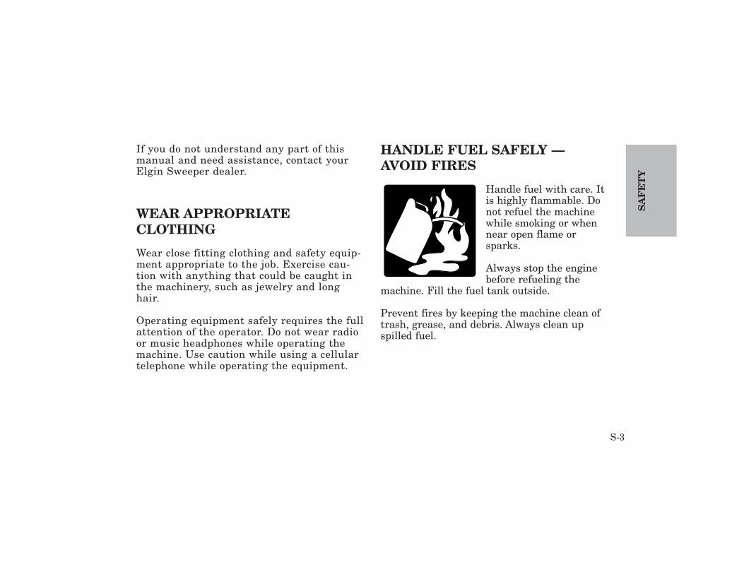
HANDLE FUEL SAFELY —AVOID FIRES
Handle fuel with care. Itis highly flammable. Donot refuel the machinewhile smoking or whennear open flame orsparks.
Always stop the enginebefore refueling the
machine. Fill the fuel tank outside.
Prevent fires by keeping the machine clean oftrash, grease, and debris. Always clean upspilled fuel.
SA
FE
TY
S-3

DRIVING THE SWEEPER
Operate the sweeper only when all guardsare fitted and in their correct position.Before moving the machine, check theimmediate vicinity of the machine forbystanders. Use the horn as a warningimmediately before moving the machine.
AVOID CONTACT WITH MOVING PARTS
Everyone must be clear of thesweeper before the engine isstarted and before the broomsare started.
Many moving parts, such as theside brooms, cannot be complete-ly shielded, due to their function.Stay clear of these moving ele-ments during operation.
Keep hands, feet, and clothing away frompower driven parts.
AVOID OVERLOADS
Observe the maximum per-missible axle loads and totalweights.
PARK SWEEPER SAFELY
Set the parking brake, turn off the engineand remove the keys.
SA
FE
TY
S-4
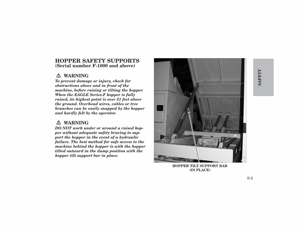
HOPPER SAFETY SUPPORTS(Serial number F-1000 and above)
WARNINGTo prevent damage or injury, check forobstructions above and in front of themachine, before raising or tilting the hopper.When the EAGLE Series-F hopper is fullyraised, its highest point is over 21 feet abovethe ground. Overhead wires, cables or treebranches can be easily snapped by the hopperand hardly felt by the operator.
WARNINGDO NOT work under or around a raised hop-per without adequate safety bracing to sup-port the hopper in the event of a hydraulicfailure. The best method for safe access to themachine behind the hopper is with the hoppertilted outward in the dump position with thehopper tilt support bar in place.
SA
FE
TY
S-5
HOPPER TILT SUPPORT BAR(IN PLACE)

WARNINGDO NOT work under a raised hopper withoutadequate safety bracing to support the hopperin the event of a hydraulic failure. If access tothe machine under the hopper is required, becertain the raised hopper safety bar is inplace.
SA
FE
TY
S-6
RAISED HOPPER SAFETY BAR(IN PLACE)
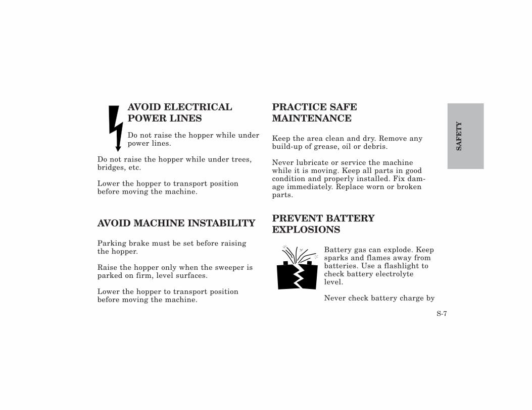
AVOID ELECTRICALPOWER LINES
Do not raise the hopper while underpower lines.
Do not raise the hopper while under trees,bridges, etc.
Lower the hopper to transport positionbefore moving the machine.
AVOID MACHINE INSTABILITY
Parking brake must be set before raisingthe hopper.
Raise the hopper only when the sweeper isparked on firm, level surfaces.
Lower the hopper to transport positionbefore moving the machine.
PRACTICE SAFE MAINTENANCE
Keep the area clean and dry. Remove anybuild-up of grease, oil or debris.
Never lubricate or service the machinewhile it is moving. Keep all parts in goodcondition and properly installed. Fix dam-age immediately. Replace worn or brokenparts.
PREVENT BATTERY EXPLOSIONS
Battery gas can explode. Keepsparks and flames away frombatteries. Use a flashlight tocheck battery electrolytelevel.
Never check battery charge by
SA
FE
TY
S-7
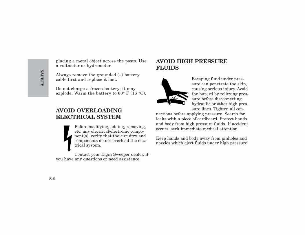
placing a metal object across the posts. Usea voltmeter or hydrometer.
Always remove the grounded (–) batterycable first and replace it last.
Do not charge a frozen battery; it mayexplode. Warm the battery to 60° F (16 °C).
AVOID OVERLOADING ELECTRICAL SYSTEM
Before modifying, adding, removing,etc. any electrical/electronic compo-nent(s), verify that the circuitry andcomponents do not overload the elec-trical system.
Contact your Elgin Sweeper dealer, ifyou have any questions or need assistance.
AVOID HIGH PRESSURE FLUIDS
Escaping fluid under pres-sure can penetrate the skin,causing serious injury. Avoidthe hazard by relieving pres-sure before disconnectinghydraulic or other high pres-sure lines. Tighten all con-
nections before applying pressure. Search forleaks with a piece of cardboard. Protect handsand body from high pressure fluids. If accidentoccurs, seek immediate medical attention.
Keep hands and body away from pinholes andnozzles which eject fluids under high pressure.
SA
FE
TY
S-8
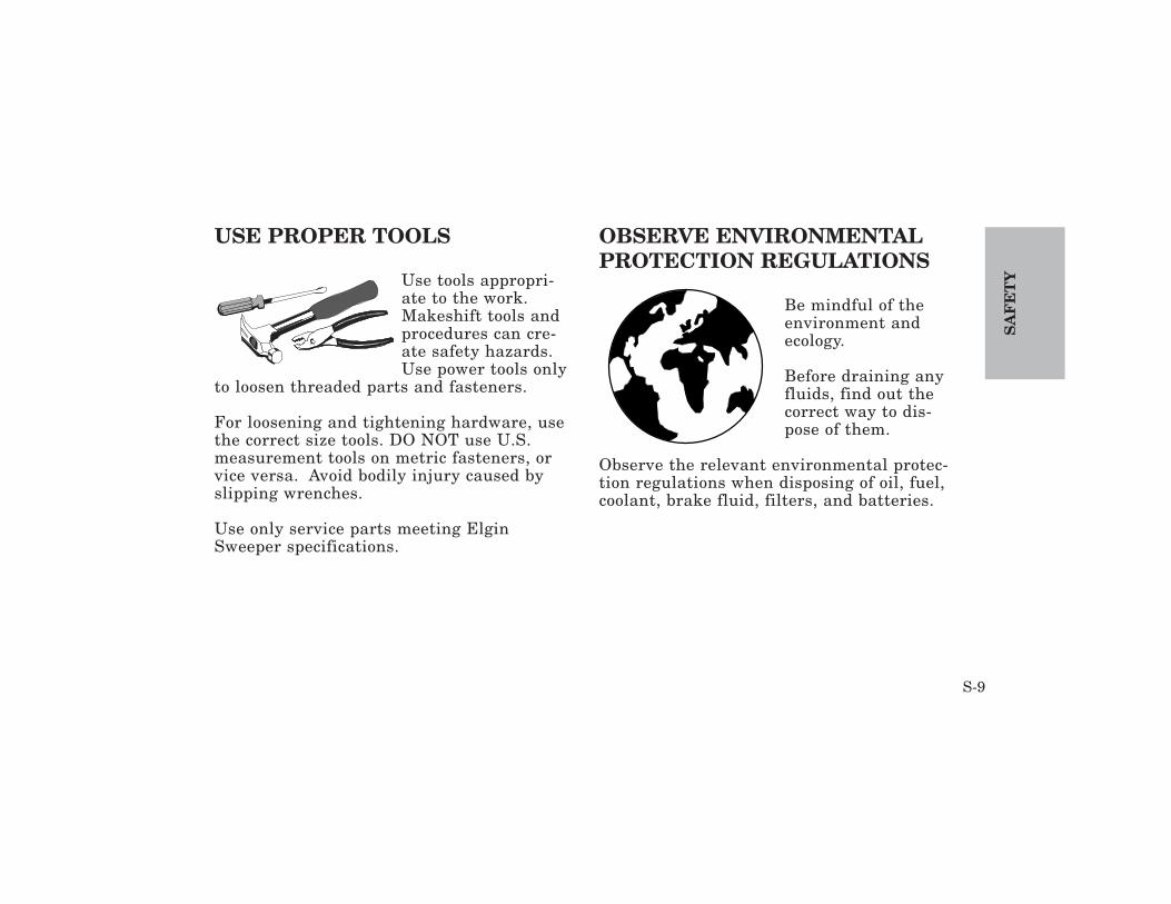
USE PROPER TOOLS
Use tools appropri-ate to the work.Makeshift tools andprocedures can cre-ate safety hazards.Use power tools only
to loosen threaded parts and fasteners.
For loosening and tightening hardware, usethe correct size tools. DO NOT use U.S.measurement tools on metric fasteners, orvice versa. Avoid bodily injury caused byslipping wrenches.
Use only service parts meeting ElginSweeper specifications.
OBSERVE ENVIRONMENTALPROTECTION REGULATIONS
Be mindful of theenvironment andecology.
Before draining anyfluids, find out thecorrect way to dis-pose of them.
Observe the relevant environmental protec-tion regulations when disposing of oil, fuel,coolant, brake fluid, filters, and batteries.
SA
FE
TY
S-9

Eagle
SA
FE
TY
S-10
EAGLE SAFETY LABELS - PART ONE OF THREE
1 2
345 F-1 3 7
F-2 6
(Start F-1000)
SA
FE
TY
S-11
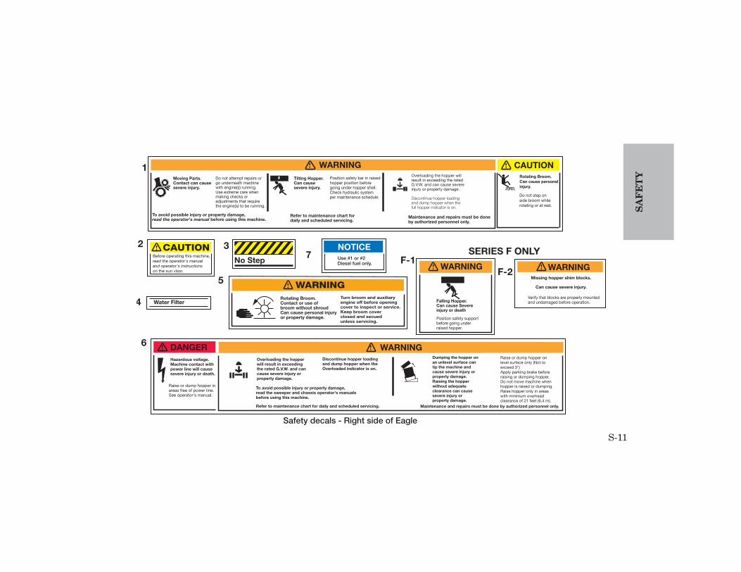
Position safety bar in raisedhopper position beforegoing under hopper shell.Check hydraulic systemper maintenance schedule.
Refer to maintenance chart fordaily and scheduled servicing.
Maintenance and repairs must be doneby authorized personnel only.
Moving Parts.Contact can cause severe injury.
Tilting Hopper.Can cause severe injury.
Do not attempt repairs orgo underneath machinewith engine(s) running.Use extreme care whenmaking checks oradjustments that requirethe engine(s) to be running.
To avoid possible injury or property damage,read the operator's manual before using this machine.
Rotating Broom.Can cause personalinjury.
Do not step on side broom while rotating or at rest.
! WARNING ! CAUTION1
2
Water Filter4
SERIES F ONLY
Falling Hopper.Can cause Severeinjury or death
! WARNING
Position safety supportbefore going underraised hopper.
F-1
3No Step
Safety decals - Right side of Eagle
Overloading the hopper willresult in exceeding the ratedG.V.W. and can cause severeinjury or property damage.
Discontinue hopper loadingand dump hopper when the full hopper indicator is on.
Before operating this machine,read the operator's manualand operator's instructionson the sun visor.
! CAUTION
Verify that blocks are properly mountedand undamaged before operation.
! WARNINGF-2Missing hopper shim blocks.
Can cause severe injury.5
Rotating Broom.Contact or use ofbroom without shroudCan cause personal injuryor property damage.
WARNING!
Turn broom and auxiliaryengine off before openingcover to inspect or service.Keep broom cover closed and secuedunless servicing.
! WARNING! DANGERHazardous voltage.Machine contact with power line will cause severe injury or death.
Raise or dump hopper inareas free of power line.See operator's manual.
Overloading the hopper will result in exceeding the rated G.V.W. and can cause severe injury or property damage.
Discontinue hopper loading and dump hopper when the Overloaded indicator is on.
To avoid possible injury or property damage,read the sweeper and chassis operator's manualsbefore using this machine.
Refer to maintenance chart for daily and scheduled servicing.
Dumping the hopper onan unlevel surface can tip the machine and cause severe injury orproperty damage. Raising the hopper without adequate clearance can causesevere injury or property damage.
Raise or dump hopper on level surface only (Not to exceed 3")Apply parking brake beforeraising or dumping hopper. Do not move machine whenhopper is raised or dumping.Raise hopper only in areaswith minimum overheadclearance of 21 feet (6.4 m).
Maintenance and repairs must be done by authorized personnel only.
6
Use #1 or #2Diesel fuel only.
7NOTICE

SA
FE
TY
S-12
EAGLE SAFETY LABELS - PART TWO OF THREE
Eagle
F-1
2 3
F-21
4
S-13
SA
FE
TY
No Step
Pressurized hydraulicreservoir.Can cause personalinjury
Vent hydraulic reservoirbefore opening drain.
CAUTION!
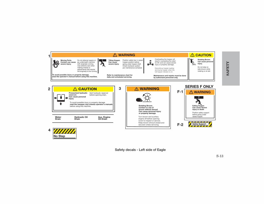
Safety decals - Left side of Eagle
To avoid possible injury or property damageread the sweeper and chassis operator's manualsbefore using this machine.
WaterDrain
Hydraulic OilDrain
Aux. EngineOil Drain
2 3
4
Position safety bar in raisedhopper position beforegoing under hopper shell.Check hydraulic systemper maintenance schedule.
Refer to maintenance chart fordaily and scheduled servicing.
Maintenance and repairs must be doneby authorized personnel only.
Moving Parts.Contact can cause severe injury.
Tilting Hopper.Can cause severe injury.
Do not attempt repairs orgo underneath machinewith engine(s) running.Use extreme care whenmaking checks oradjustments that requirethe engine(s) to be running.
To avoid possible injury or property damage,read the operator's manual before using this machine.
Rotating Broom.Can cause personalinjury.
Do not step on side broom while rotating or at rest.
! WARNING ! CAUTION1Overloading the hopper willresult in exceeding the ratedG.V.W. and can cause severeinjury or property damage.
Discontinue hopper loadingand dump hopper when the full hopper indicator is on.
Rotating Broom.Contact or use ofbroom without shroudCan cause personal injuryor property damage.
WARNING!
Turn broom and auxiliaryengine off before opening cover to inspect or service.Keep broom shroud closed andsecured unless servicing.
Falling Hopper.Can cause Severeinjury or death
! WARNING
SERIES F ONLY
Safety Support
Position safety supportbefore going underraised hopper.
F-1
F-2

SA
FE
TY
S-14
EAGLE SAFETY LABELS - PART THREE OF THREE
12
3
4
5
33
7
6
8
(Up to F-999)
S-15
SA
FE
TY
Change hydraulic oiland flush tankevery six months.
NOTICE1 Anti-Freeze
Use #1 or #2Diesel fuel only.
NOTICE
! WARNING
Keep clear of fan at alltimes. Disconnect batterybefore servicing.
Rotating Fan.Can cause severe injury.
Ethylene Glycol BaseCoolantDate__________ Qts____Protected To___________
6
7
4
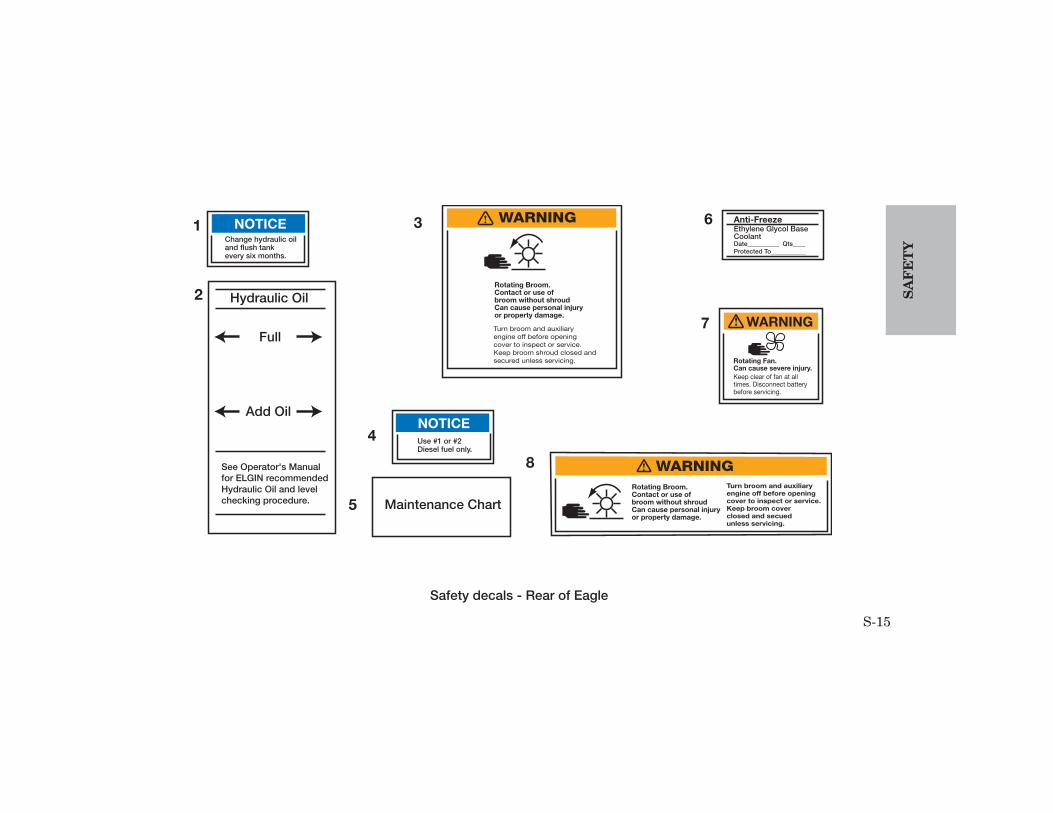
Safety decals - Rear of Eagle
3
Maintenance Chart
Hydraulic Oil
Full
Add Oil
See Operator's Manualfor ELGIN recommendedHydraulic Oil and levelchecking procedure.
2
5
Rotating Broom.Contact or use ofbroom without shroudCan cause personal injuryor property damage.
WARNING!
Turn broom and auxiliaryengine off before opening cover to inspect or service.Keep broom shroud closed andsecured unless servicing.
Rotating Broom.Contact or use ofbroom without shroudCan cause personal injuryor property damage.
WARNING!
Turn broom and auxiliaryengine off before openingcover to inspect or service.Keep broom cover closed and secuedunless servicing.
8
NOTICE

SA
FE
TY
S-16
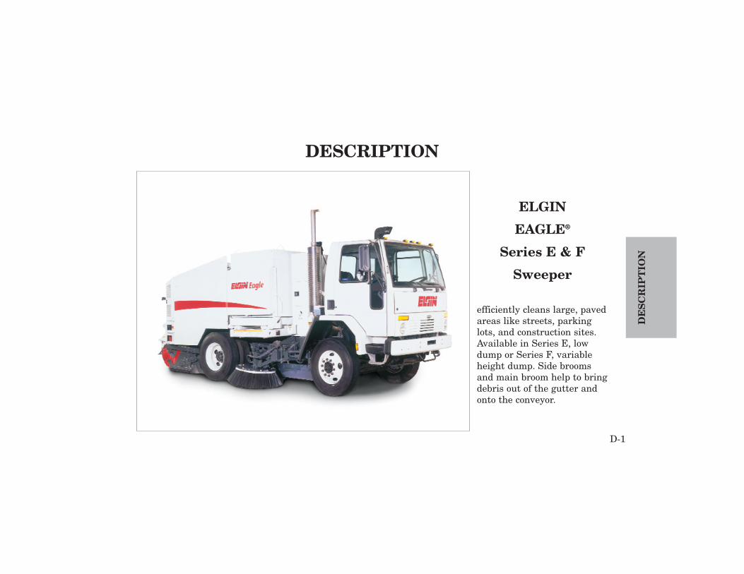
ELGIN
EAGLE®
Series E & F
Sweeper
efficiently cleans large, pavedareas like streets, parkinglots, and construction sites.Available in Series E, lowdump or Series F, variableheight dump. Side broomsand main broom help to bringdebris out of the gutter andonto the conveyor.
D-1
DE
SC
RIP
TIO
N
DESCRIPTION

WHY SWEEP?
Street sweeping is an essential part of sanitation.In health, ecology and aesthetics, the communitybenefits from clean streets. Clean streets reducedust and dust-borne contaminants, bacteria fromdecomposition of organic matter, pollutants enter-ing stormwater systems and accidents due to debrisin the roadway. Community pride is enhanced by aclean environment. People are less likely to litter ina clean area. Tourists have a positive first impres-sion of the community, which may encourage themto stay longer and return more often.
HISTORY OF SWEEPING
At the turn of the century, streets were in terriblecondition. Most were unpaved, creating dust in dryseasons and mud in rainy seasons and harboringdisease-producing bacteria. Gradually streets werepaved with cobblestones and bricks. This decreased,
but did not eliminate dust and mud. Droppingsfrom horses, garbage, paper and other litter alsoneeded to be removed. As populations grew, so didthis problem. By 1914 motorized vehicles werebecoming more popular, displacing horse-drawnvehicles and replacing one set of problems with
DE
SC
RIP
TIO
N
D-2
HISTORY OF SWEEPINGPRINCIPLES OF OPERATION
Figure D-11914 Elgin Sweeper in Boise, Idaho

another. That year Boise, Idaho received the firstmotorized street sweeper (Figure D-1), manufac-tured by Elgin Sweeper.
As society changed, the demands on sweepers alsochanged. Litter, dust, leaves and grass still remain.Add to that sand and salt from the winter’s snowremoval and metal and rubber from cars andtrucks. Airport runways must be kept immaculate;a small piece of metal on a runway can cause havocwith a jet engine. Parking lots and garages havereplaced stables. Environmental concerns mean notonly cleaning the streets, but keeping the collecteddebris out of the air and waterways.
In 1964 Elgin introduced the most popular sweeperever, the Pelican, a mechanical sweeper. Elgin’sfirst vacuum sweeper, the Whirlwind, entered themarket in 1969 and in 1983 the Crosswind, a recir-culating air sweeper joined the ranks of Elginstreet sweepers. Next, in 1988 came the Eagle, afour-wheel mechanical sweeper that can be drivenat highway speeds. The year 1996 saw the additionof the Fast Sweeping Crosswind FSX and the
GeoVac to the product line.These sweepers answerthe needs of the modern community.
The acquisition of Vactor Manufacturing by FederalSignal Corporation, Elgin Sweeper's parent compa-ny, added the vacuum sweeper, Sunvac III, to theElgin product line in 1994.
MECHANICAL/BROOM SWEEPERS
Mechanical, or broom, sweepers remove debris bysweeping it onto a conveyor. The conveyor carriesthe debris to a hopper. The No-Jam™ hopper con-veyor of Elgin Eagle was originally patented. Thisrevolutionary design sweeps debris up onto the con-veyor, eliminating the problems of jamming.
EAGLEThe Eagle offers the patented No-Jam ™ conveyorof the world’s most popular sweeper, the ElginPelican, in a 4-wheel sweeper capable of travellingat highway speeds between sweep locations. TheEagle picks up large objects, such as branches, hub
D-3
DE
SC
RIP
TIO
N

caps and bottles. When the debris hopper is full,the Eagle hopper dumps onto the ground or at avariable height up to 9.5 ft. (2895 mm) with SeriesF Eagle.
WATER SPRAY
A water spray system controls dust during sweep-ing. Three nozzles at the front edge of each side
broom and three more at the main broom spraywater to moisten the dust being swept by thebrooms.
The Elgin-designed centrifugal water pump canrun-dry without damage.
The amount of water is adjustable through use of aswitch inside the cab. Large 280-gallon (1060 L)polyethylene water tank (Figure F-2) capacity isstandard on the Eagle.
DE
SC
RIP
TIO
N
D-4
Figure D-2Water tank (One of two)

BROOMS
Hydraulically-driven brooms sweep the debris onthe street onto the conveyor. The main broom islocated behind the lower edge of the conveyor anddirects the debris toward the conveyor.
Large 42 in. (1.1 m) side brooms (Figure D-3) areavailable on both the right and left sides. Forsweeping these are lowered and rotated to movegutter debris to the conveyor. Speed of the broomsis controlled in-cab, independently of the truckengine speed.
Digging pressure on all brooms is controlled fromthe cab. The pattern that the brooms produce whenthe sweeper is stationary is a tool to evaluate themost efficient positioning and pressure of thebrooms. The brooms can be adjusted to produce thebest pattern and the best result.
CONVEYOR
The heavy-duty, No Jam™ debris conveyor (FigureD-4) transports debris deposited on it by the mainbroom to the hopper. The high-strength belt-typeconveyor conveys bulky items to the hopper withoutjamming.
Conveyor speed is controlled from in-cab and canreverse without reversing the brooms.Conveyorspeed is independent of the truck engine speed.
D-5
DE
SC
RIP
TIO
N
Figure D-3Side broom

DE
SC
RIP
TIO
N
D-6
Figure D-4Eagle cross section showing conveyor and hopper
Pavement contact is maintained by rubber dirtshoes on the sides and rubber deflectors under thechassis. Optional carbide dirt shoes are available.
HOPPER
The side dump hopper (Figure D-4) is center-mounted for the best possible stability. With a volu-metric capacity of 5.5 cu. yd. (4.2 cu.m) the EagleSeries E debris hopper can handle a material vol-ume of 4.5 cu. yd. (3.4 cu. m.) to be dumped at hop-per height.
The Eagle series F hopper can hold a volumetriccapacity of 4.12 cu. yd. (3.2 cu.m) for a material vol-ume of 3 cu. yd. (2.3 cu.m) to be dumped at a vari-able dump height of 9.5 ft (2.9 m) when measuredat the bottom of the discharge door.
After dumping the hopper should be washed downfor maximum efficiency and long life.
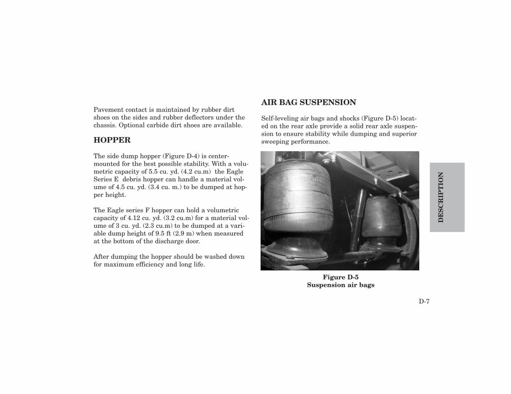
AIR BAG SUSPENSION
Self-leveling air bags and shocks (Figure D-5) locat-ed on the rear axle provide a solid rear axle suspen-sion to ensure stability while dumping and superiorsweeping performance.
D-7
DE
SC
RIP
TIO
N
Figure D-5Suspension air bags

Operator comfort is improved by this suspensiondue to the minimizing of rough road conditions. Thesweeper remains level, regardless of the load.
CONTROLS
Controls for all sweeping functions, includingbrooms and hopper, are powered through in-cabcontrols (Figure D-5), located comfortably withinreach.
For a complete description of all controls, see theOperation Section.
DE
SC
RIP
TIO
N
D-8
Figure D-4Eagle in-cab controls
D-9
DE
SC
RIP
TIO
N
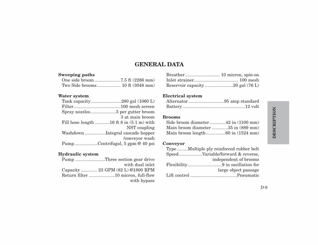
Sweeping pathsOne side broom .....................7.5 ft (2286 mm)Two Side brooms ................... 10 ft (3048 mm)
Water systemTank capacity.........................280 gal (1060 L)Filter ......................................100 mesh screenSpray nozzles.....................3 per gutter broom
3 at main broomFill hose length ............16 ft 8 in (5.1 m) with
NST couplingWashdown .................Integral cascade hopper
/conveyor washPump...................Centrifugal, 5 gpm @ 40 psi
Hydraulic systemPump ........................Three section gear drive
with dual inletCapacity ............. 23 GPM (82 L) @1800 RPMReturn filter .....................10 micron, full-flow
with bypass
Breather ............................ 10 micron, spin-onInlet strainer.................................... 100 meshReservoir capacity .......................20 gal (76 L)
Electrical system Alternator .............................95 amp standardBattery ...................................................12 volt
BroomsSide broom diameter .............42 in (1100 mm)Main broom diameter .............35 in (889 mm)Main broom length................60 in (1524 mm)
ConveyorType .........Multiple ply reinforced rubber beltSpeed...................Variable/forward & reverse,
independent of broomsFlexibility............................9 in oscillation for
large object passageLift control ......................................Pneumatic
GENERAL DATA

DE
SC
RIP
TIO
N
D-10
Debris Hopper - SERIES FMaximum dump height (Bottom ofdischarge door)......Up to 9 ft 6 in (2895 mm)
Design lift capacity ..........9,000 lbs (4,080 kg)Volumetric capacity .............. 4.12 yd3 (3.2 m3)Material volume..........................3 yd3 (2.3 m3)Maximum hopper dump angle .................. 45°Lifting method ....................... Single cylinder,
triple stage mast
Debris Hopper - SERIES EMaximum dump height (Bottom ofdischarge door) .........................26 in (70 mm)
Design lift capacity ........13,500 lbs (6,124 kg)Volumetric capacity ................ 5.5 yd3 (4.2 m3)Material volume.......................4.5 yd3 (3.4 m3)Maximum hopper dump angle .................. 50°
Fuel tank capacityStandard .................... common 50 gal (190 L)
Auxiliary EngineIsuzu Diesel Model C-240
Cylinders ............................................4, in-lineDisplacement ..........................144 CID (2.3 L)Horsepower ..............49 HP (40 kW) governed
@ 2500 RPMTorque.......... 115 lb-ft (156 Nm) @ 2000 RPMCompression Ratio ................................... 20:1Bore........................................ 3.39 in (86 mm)Stroke................................... 4.02 in (102 mm)
Refill capacitiesEngine crankcase with filter .....13.5 qt (13 L)Hydraulic system ...................140 qt (135.2 L)
NOTICEElgin Sweeper Company recommends Texaco RandoHDZ 68 or equivalent hydraulic oil.. Use of anyfluid not approved by Elgin Sweeper Company canvoid all hydraulic component warranties.

Eagle
D-11
DE
SC
RIP
TIO
N
Figure D-7 Eagle F Side View
Hopper
Side broom
Auxiliary engine compartment
Main broom Dirt shoe Centerboard Side broom light
Beacon light
Conveyor

DE
SC
RIP
TIO
N
D-12
Figure D-9Eagle F Rear View
Main broom Side broomSide broom
Rear engine compartmentBeacon light
Air pre-cleaner
Main broom shroud

Before operating the Elgin Eagle, be certain thatyou have read and understand all safety and opera-tion information. If you have any questions, contactyour supervisor before proceeding.
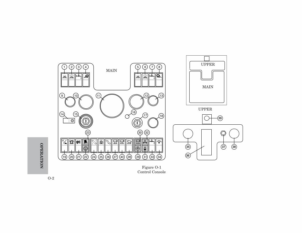
INSTRUMENTS AND CONTROLS
The numbers below refer to those indicated onFigure O-1 on page O-2.
1 LEFT SIDE BROOM IN / OUT -Controls movement of the left side broom inand out. Press switch until broom is fullyextended.
2 LEFT SIDE BROOM UP / DOWN /ROTATE - Controls up and down movementand rotation of left side broom. After sidebroom is extended (Switch #1), press thisswitch forward to lower and rotate the broom.
3 LEFT SIDE BROOM SPRAY WATERON / OFF - Turns the spray water at the leftside broom and main broom on and off.
4 LEFT SIDE BROOM LIGHT ON /OFF - Turns the light at the left side broom onand off.
5 RIGHT SIDE BROOM IN / OUTControls movement of the left side broom inand out. Press switch until broom is fullyextended.
6 RIGHT SIDE BROOM UP / DOWN /ROTATE - Controls up and down movementand rotation of right side broom. After sidebroom is extended (Switch #5), press thisswitch forward to lower and rotate the broom.
O-1
OP
ER
AT
ION
OPERATION
OP
ER
AT
ION
O-2
1 2 3 4
9
14 15
10 11 1312
181716
23 30 32
19 20 21 22 24 4025 26 27 28 29 31 33 34
5 6 7 8
Figure O-1Control Console
35 37 38
39
36
UPPER
MAIN
MAIN
UPPER

7 RIGHT SIDE BROOM SPRAY WATERON / OFF - Turns the spray water at the rightside broom and main broom on and off.
8 RIGHT SIDE BROOM LIGHT ON /OFF - Turns the light at the right side broomon and off.
9 LEFT SIDE BROOM PRESSUREREGULATOR - Regulates the downwardpressure on the left side broom. Lift lockingknob and turn to adjust. Push down on lockingknob to lock at desired pressure setting.
10 COOLANT TEMPERATURE GAUGE -Indicates the temperature of the enginecoolant. If the needle nears the highest tem-perature, stop and check the level of thecoolant.
11 TACHOMETER/HOUR METER -Indicates the speed of the engine in thousandsof revolutions per minute (rpm). After initial
start-up idling, hour meter records engine run-ning hours.
12 OIL PRESSURE GAUGE - Indicatesengine oil pressure. If the needle indicates lowoil pressure, stop and check the oil level.
13 RIGHT SIDE BROOM PRESSUREREGULATOR - Regulates the downwardpressure on the right side broom. Lift lockingknob and turn to adjust. Push down on lockingknob to lock at desired pressure setting.
14 STEERING CIRCUIT CONTROL -Switches the dualized chassis steering fromleft to right.
15 CHASSIS ENGINE IGNITION - SeeOperator’s Manual for truck chassis.
16 AUXILIARY ENGINE RUN LIGHT -When on, indicates that the auxiliary engine isrunning.
O-3
OP
ER
AT
ION

17 AUXILIARY ENGINE IGNITION -Turns the auxiliary engine, which powers thesweeping functions, on and off.
18 MAIN BROOM PRESSURE REGULA-TOR - Regulates the downward pressure onthe main broom. Lift locking knob and turn toadjust. Push down on locking knob to to lock atdesired pressure setting.
19 SWEEP/TRANSPORT CIRCUITSELECT - Switches the sweeper from sweepto transport mode.
20 BEACON LIGHT ON/OFF (Optional)- Turns the optional beacon light on and off.
21 FLOODLIGHT ON/OFF - Turns thefloodlight on and off. The right hand rearfloodlight is standard. An optional Left handfloodlight is available.
22 HYDRAULIC FILTER RESTRICTIONINDICATOR - Indicates that the return filterat the hydraulic fluid reservoir is clogged andin need of service.
23 TILT WARNING INDICATOR -Indicates that the machine is not level. If thislight is on, the hopper must NOT be raised.
24 CONVEYOR UP/DOWN - Controls thelowering and raising of the conveyor. Pressingforward on the switch puts the conveyor anddirt shoes into sweep position. Pressing rear-ward raises conveyor and dirt shoes to trans-port position.
25 MAIN BROOM UP / DOWN / ROTATE- Controls the raising, lowering and rotation ofthe main broom. Pressing forward on switchwill lower and rotate the main broom. Pressingrearward will raise broom and stop rotation.
OP
ER
AT
ION
O-4
26 CONVEYOR ROTATE ON/OFF -Controls the rotation of the conveyor, both for-ward and reverse. Pressing forward will rotateconveyor forward. Pressing rearward willrotate conveyor rearward.
27 HOPPER UP/DOWN (F-Series Only)-Raises and lowers the hopper. Press forwardon switch to raise hopper until desired positionis reached. Press rearward to lower hopper.
28 HOPPER DUMP - Causes the hopper todump and to roll back to normal position.Pressing forward will open hopper door andtilt the hopper. Pressing rearward will rollback the hopper and close hopper door.
29 AIR FILTER RESTRICTION INDICA-TOR - Indicates that the engine air filter isclogged and in need of service.
30 HOPPER UP INDICATOR - Indicatesthat the hopper is in a raised position.
31 NO SPRAY WATER INDICATOR -Indicates that the supply in the water tankhas been completely used up. Fill water tankto turn off indicator.
32 HOPPER FULL INDICATOR -Indicates that the hopper has reached its max-imum weight limit.
33 SPRAY WATER FLOW - A three-wayswitch that controls the volume of waterused..Can be set for Low, Medium or High
34 SHUTDOWN OVERRIDE (optional) -Automatic engine shutdown protects againstdamage from high coolant temperature, lowengine oil pressure or low hydraulic oil level.To start an engine with this feature, depressthis switch while starting the engine.
35 MAIN BROOM AIR PRESSUREGAUGE - Indicates digging pressure of themain broom. A lower pressure indicates
O-5
OP
ER
AT
ION
greater digging force. A higher pressure indi-cates less digging force.
36 GEAR SHIFT SELECTOR - See chassismanufacturer’s Operator’s Manual.
37 AUXILIARY ENGINE THROTTLECONTROL- To raise engine rpm, depress but-ton on throttle knob to relase lock and pullthrottle knob up. For fine adjustments rotateknob.
38 SIDE BROOM AIR PRESSUREGAUGE (optional) - In digging pressure of theside broom(s). Lower pressure indicatesgreater digging force. A higher pressure indi-cates less digging force.
39 AIR BRAKE
40 HOPPER SIDE SHIFT OUT/OFF/IN -Moves the hopper horizontally.
OPERATING CHECKLIST
Successful operation of the Eagle depends on thefollowing standard daily procedures.
Always follow all recommendations of the chassismanufacturer.
Engine (Auxiliary and Truck)Always follow all recommendation of the truck andauxiliary engine manufacturers.
• Check engine oil level.• Check radiator coolant level.• Check battery fluid level (if applicable).• Check belts for wear and proper tension.
NOTICEUse #1 or #2 diesel fuel only.
• Check fuel tank. Fill, if necessary. Filling thetank at the end of the shift will prevent conden-sation in the tank as moist air cools.
• Clean engine pre-cleaner (if applicable).
OP
ER
AT
ION
O-6

• Check and clean the engine air filter if necessary.• Drain the water separator on the fuel filter.• Check hydraulic oil reservoir level.
Lights, Mirrors, Tires
• Check directional and safety lights.• Check backup alarm.• Check tires for correct pressure, according to tire
manufacturer.• Check mirrors for visibility.• Check windshield wipers and wiper fluid.
Spray Water
• Check spray water filter.
• Fill water tank after flushing hydrant. Flushhydrant before connecting to fill hose to removeimpurities in the water. Fill to overflowing.
Sweeping Components
• Build up air pressure to check sweep functions.• Check dirt shoes and dirt deflectors for wear and
for proper adjustment.• Check main broom for wear.• Check side brooms for wear.• Check main broom pattern.• Check side broom patterns.• Check centerboard dirt deflector for wear and
adjustment.• Check conveyor for wear and alignment.
O-7
OP
ER
AT
ION
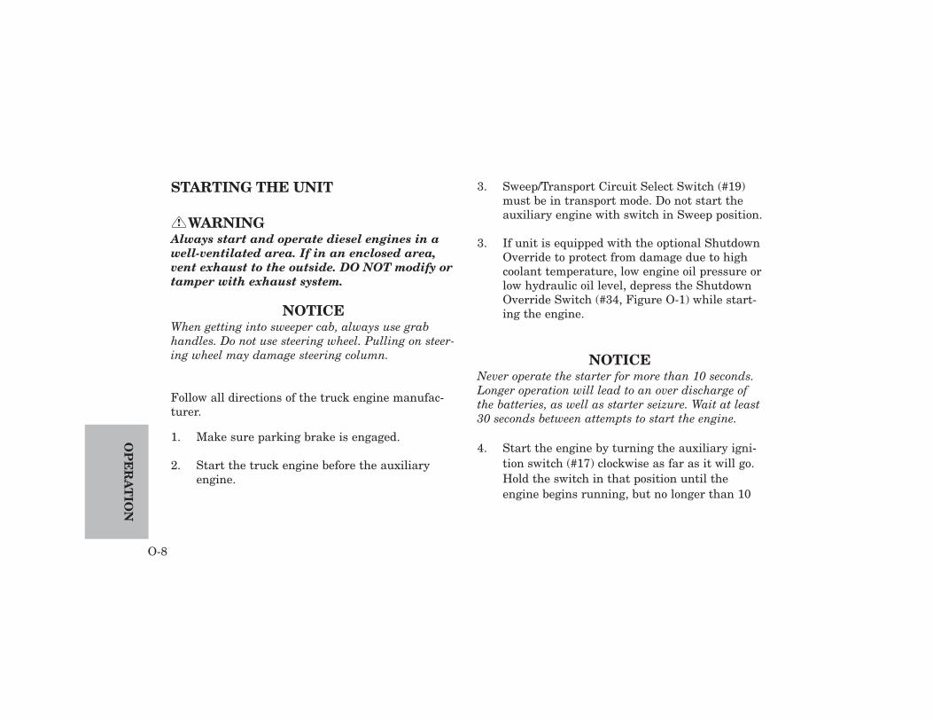
STARTING THE UNIT
WARNINGAlways start and operate diesel engines in awell-ventilated area. If in an enclosed area,vent exhaust to the outside. DO NOT modify ortamper with exhaust system.
NOTICEWhen getting into sweeper cab, always use grabhandles. Do not use steering wheel. Pulling on steer-ing wheel may damage steering column.
Follow all directions of the truck engine manufac-turer.
1. Make sure parking brake is engaged.
2. Start the truck engine before the auxiliaryengine.
3. Sweep/Transport Circuit Select Switch (#19)must be in transport mode. Do not start theauxiliary engine with switch in Sweep position.
3. If unit is equipped with the optional ShutdownOverride to protect from damage due to highcoolant temperature, low engine oil pressure orlow hydraulic oil level, depress the ShutdownOverride Switch (#34, Figure O-1) while start-ing the engine.
NOTICENever operate the starter for more than 10 seconds.Longer operation will lead to an over discharge ofthe batteries, as well as starter seizure. Wait at least30 seconds between attempts to start the engine.
4. Start the engine by turning the auxiliary igni-tion switch (#17) clockwise as far as it will go.Hold the switch in that position until theengine begins running, but no longer than 10
!
OP
ER
AT
ION
O-8
seconds. If the engine fails to start within 10seconds, wait at least 30 seconds before tryingagain.
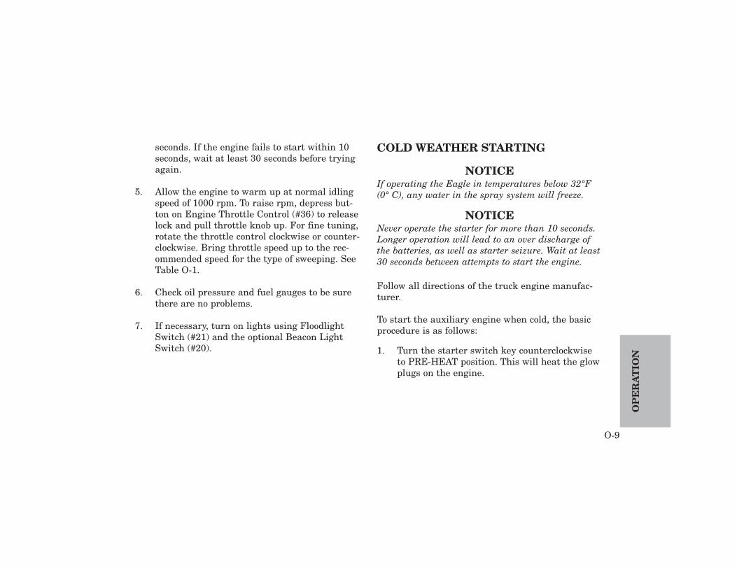
5. Allow the engine to warm up at normal idlingspeed of 1000 rpm. To raise rpm, depress but-ton on Engine Throttle Control (#36) to releaselock and pull throttle knob up. For fine tuning,rotate the throttle control clockwise or counter-clockwise. Bring throttle speed up to the rec-ommended speed for the type of sweeping. SeeTable O-1.
6. Check oil pressure and fuel gauges to be surethere are no problems.
7. If necessary, turn on lights using FloodlightSwitch (#21) and the optional Beacon LightSwitch (#20).
COLD WEATHER STARTING
NOTICEIf operating the Eagle in temperatures below 32°F(0° C), any water in the spray system will freeze.
NOTICENever operate the starter for more than 10 seconds.Longer operation will lead to an over discharge ofthe batteries, as well as starter seizure. Wait at least30 seconds between attempts to start the engine.
Follow all directions of the truck engine manufac-turer.
To start the auxiliary engine when cold, the basicprocedure is as follows:
1. Turn the starter switch key counterclockwiseto PRE-HEAT position. This will heat the glowplugs on the engine.
O-9
OP
ER
AT
ION

The pre-heat time required varies according tothe type of pre-heating system.
WITH INDICATION LAMP:The indication lamp will go off in 20 seconds.
WITH CONTROL RESISTANCE:The control resistance coil will heat red in 25to 30 seconds.
2. Turn the starter switch key clockwise toSTART position as soon as the indication lampgoes off or the control resistance coil redheats..
TRANSPORT
CAUTIONWith dual steering — Turning both steeringwheels at the same time will damage the steer-ing mechanism. Use only one steering wheel ata time to steer the Eagle.
1. Release parking brake.
2. Side broom(s) and main broom must bestopped. Brooms and conveyor must be raisedbefore transport. If necessary, stop side broomrotation (right - #6, left - #2), main broom rota-tion (#25) and conveyor rotation (#26).Stopping rotation will raise the brooms. Raisethe conveyor using Conveyor Up / Down (#24).
!
OP
ER
AT
ION
O-10
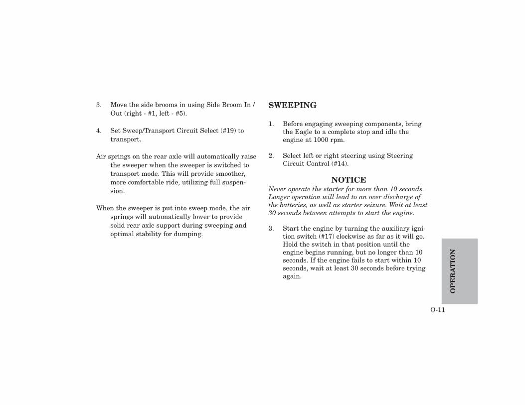
3. Move the side brooms in using Side Broom In /Out (right - #1, left - #5).
4. Set Sweep/Transport Circuit Select (#19) totransport.
Air springs on the rear axle will automatically raisethe sweeper when the sweeper is switched totransport mode. This will provide smoother,more comfortable ride, utilizing full suspen-sion.
When the sweeper is put into sweep mode, the airsprings will automatically lower to providesolid rear axle support during sweeping andoptimal stability for dumping.
SWEEPING
1. Before engaging sweeping components, bringthe Eagle to a complete stop and idle theengine at 1000 rpm.
2. Select left or right steering using SteeringCircuit Control (#14).
NOTICENever operate the starter for more than 10 seconds.Longer operation will lead to an over discharge ofthe batteries, as well as starter seizure. Wait at least30 seconds between attempts to start the engine.
3. Start the engine by turning the auxiliary igni-tion switch (#17) clockwise as far as it will go.Hold the switch in that position until theengine begins running, but no longer than 10seconds. If the engine fails to start within 10seconds, wait at least 30 seconds before tryingagain.
O-11
OP
ER
AT
ION
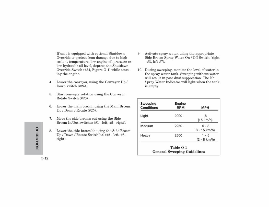
If unit is equipped with optional ShutdownOverride to protect from damage due to highcoolant temperature, low engine oil pressure orlow hydraulic oil level, depress the ShutdownOverride Switch (#34, Figure O-1) while start-ing the engine.
4. Lower the conveyor, using the Conveyor Up /Down switch (#24).
5. Start conveyor rotation using the ConveyorRotate Switch (#26).
6. Lower the main broom, using the Main BroomUp / Down / Rotate (#25).
7. Move the side brooms out using the SideBroom In/Out switches (#1 - left, #5 - right).
8. Lower the side broom(s), using the Side BroomUp / Down / Rotate Switch(es) (#2 - left, #6 -right).
9. Activate spray water, using the appropriateSide Broom Spray Water On / Off Switch (right- #3, left #7).
10. During sweeping, monitor the level of water inthe spray water tank. Sweeping without waterwill result in poor dust suppression. The NoSpray Water Indicator will light when the tankis empty.
OP
ER
AT
ION
O-12
Sweeping EngineConditions RPM MPH
Light 2000 8(15 km/h)
Medium 2250 5 - 88 - 15 km/h)
Heavy 2500 1 - 5(2 - 8 km/h)
Table O-1General Sweeping Guidelines
11. During sweeping, adjust the amount of spraywater using Spray Water Flow (#33).
12. If necessary, turn on lights using:Side Broom Light Switch (left-#4, right-#8)Beacon Light Switch (optional) (#20)Floodlight Switch (standard for right side,
optional for left side) (#21).
13. Use the Engine Throttle Control (#36) to setthe recommended rpm according to sweepingconditions. See Chart O-1 for rpm and mph.
14. Shift transmission to Neutral.
15. Shift two-speed axle to Low.
16. Shift transmission to desired range for sweep-ing.
Sweeping with the axle in low range and the trans-mission in first gear will improve ground speedcontrol and reduce the need to apply the brakes.This will also allow system air pressure to be main-tained more easily.
The side mirror must be correctly adjusted to viewside broom operation and location.
If during sweeping objects become jammed in theconveyor, the conveyor can be reversed. theConveyor Rotate switch (#26) should be put in theneutral (center) position to stop the conveyor, thenpressed rearward to reverse the conveyor.
NOTICENever operate the conveyor in reverse for more than30 seconds. Doing so may cause misalignment of thebelt and result in damage.
NOTICEIf the sweeper itself is shifted into reverse, the ElginEagle will automatically raise the sweeping compo-nents. These components will return to sweepingpositions when the sweeper is shifted back to neu-tral or drive.
O-13
OP
ER
AT
ION
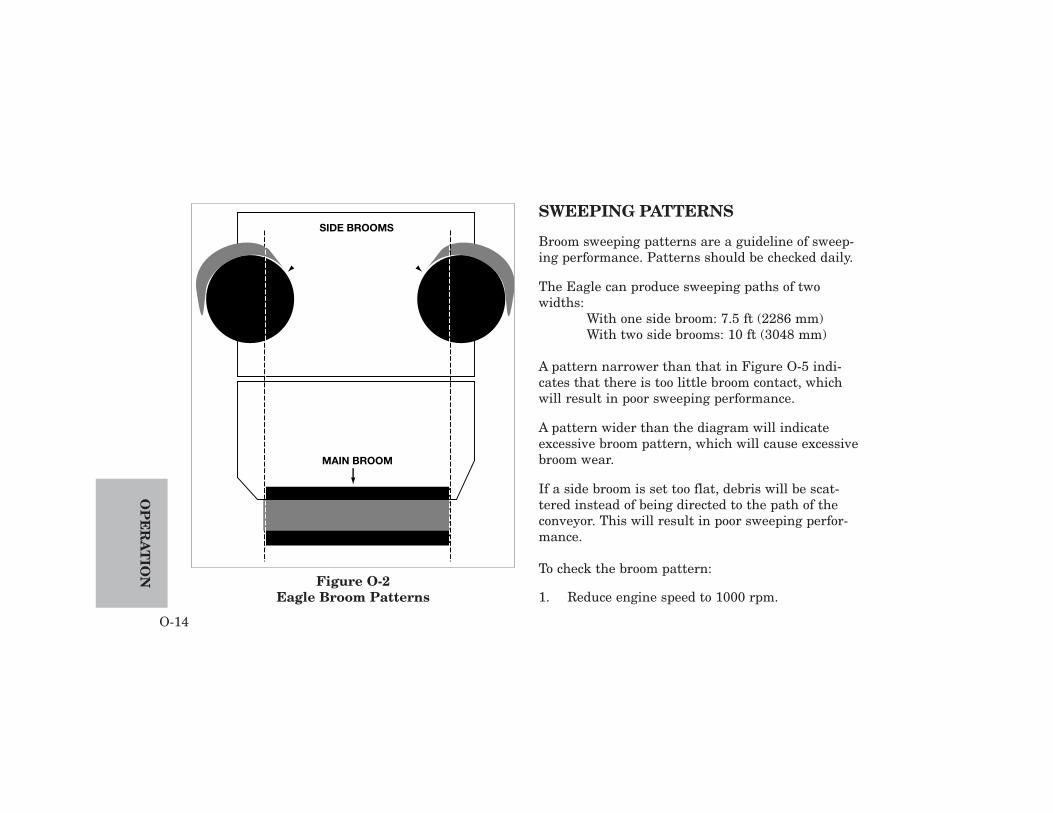
SWEEPING PATTERNS
Broom sweeping patterns are a guideline of sweep-ing performance. Patterns should be checked daily.
The Eagle can produce sweeping paths of twowidths:
With one side broom: 7.5 ft (2286 mm)With two side brooms: 10 ft (3048 mm)
A pattern narrower than that in Figure O-5 indi-cates that there is too little broom contact, whichwill result in poor sweeping performance.
A pattern wider than the diagram will indicateexcessive broom pattern, which will cause excessivebroom wear.
If a side broom is set too flat, debris will be scat-tered instead of being directed to the path of theconveyor. This will result in poor sweeping perfor-mance.
To check the broom pattern:
1. Reduce engine speed to 1000 rpm.
OP
ER
AT
ION
O-14
Figure O-2Eagle Broom Patterns
MAIN BROOM
SIDE BROOMS
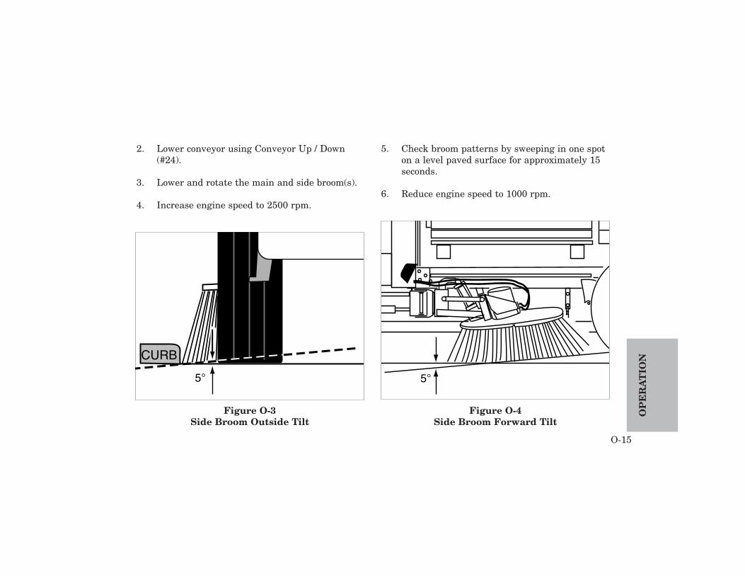
2. Lower conveyor using Conveyor Up / Down(#24).
3. Lower and rotate the main and side broom(s).
4. Increase engine speed to 2500 rpm.
5. Check broom patterns by sweeping in one spoton a level paved surface for approximately 15seconds.
6. Reduce engine speed to 1000 rpm.
O-15
OP
ER
AT
ION
5°
CURB
Figure O-3Side Broom Outside Tilt
5°
Figure O-4Side Broom Forward Tilt
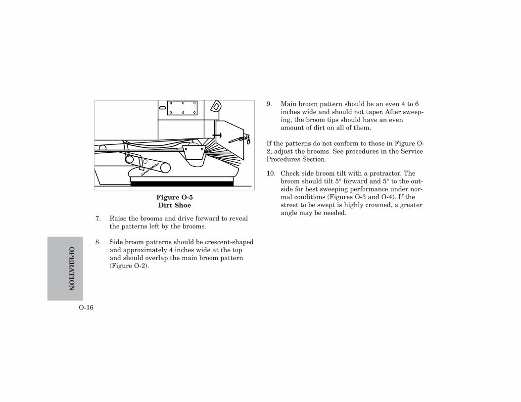
7. Raise the brooms and drive forward to revealthe patterns left by the brooms.
8. Side broom patterns should be crescent-shapedand approximately 4 inches wide at the topand should overlap the main broom pattern(Figure O-2).
9. Main broom pattern should be an even 4 to 6inches wide and should not taper. After sweep-ing, the broom tips should have an evenamount of dirt on all of them.
If the patterns do not conform to those in Figure O-2, adjust the brooms. See procedures in the ServiceProcedures Section.
10. Check side broom tilt with a protractor. Thebroom should tilt 5° forward and 5° to the out-side for best sweeping performance under nor-mal conditions (Figures O-3 and O-4). If thestreet to be swept is highly crowned, a greaterangle may be needed.
OP
ER
AT
ION
O-16
Figure O-5Dirt Shoe

Procedures to adjust side broom tilt are located inthe Service Procedures Section.
While checking the broom patterns, also check thedirt shoes (Figure O-5) on each side of the mainbroom.
The dirt shoe housings should be flush with themain broom.
The dirt shoes should be level with the ground.Procedures for adjusting the dirt shoes are in theService Procedures Section.
REVERSING THE CONVEYOR
The conveyor may be reversed, if necessary, forexample, during washdown or if an object isjammed in the conveyor.
NOTICEDo not operate the conveyor in reverse for more than30 seconds. Doing so may cause misalignment of theconveyor belt and subsequent damage.
To reverse the conveyor, press the 3-positionConveyor Rotate Switch (#28) to Off and then toReverse.
O-17
OP
ER
AT
ION
DUMPING THE HOPPER
DANGERBefore dumping the hopper check for adequateside and overhead clearance. Avoid all powerlines, bridges, trees and any other possiblehazards.
Series E sweeper requires approximately 50 in.(1.3 m) side clearance and 12.5 ft (3810 mm)overhead clearance.
Series F sweeper requires side by side align-ment with receptacle. The hopper may tiltfrom a raised position of 11 in. (280 mm) up to11.5 ft. (3505 mm). An overhead clearance of 21ft. (6400 M) is required for Series F.
CAUTIONOverloading the hopper can cause personalinjury or damage to the sweeper. Dump hopperfrequently when loading heavy materials. DoNOT exceed Gross Vehicle Weight. If Full LoadIndicator (#33, Figure O-1) is lit, stop sweep-ing and dump hopper.
1. Come to a complete stop on a level surface,aligned with debris receptacle or desiredground location.
2. Shift transmission to neutral.
3. Make sure parking brake is engaged.
NOTICEThe rear suspension air bags must be deflated(Sweep Mode) prior to dumping. The conveyor mustbe in the raised position. Interlock switches preventdumping, if the suspension and conveyor are notproperly positioned.
!
!
OP
ER
AT
ION
O-18

4. Put sweeper into sweep mode, using Sweep /Transport Circuit Select (#19).
5. Check Tilt Level Indicator (#23) to make suresweeper is level. If this indicator light is on,move sweeper to level ground.
6. Stop rotation of conveyor, main broom and sidebroom(s) and raise using - Conveyor Rotate Switch (#26),- Conveyor Up / Down (#24)- Main Broom Rotate / Up / Down (#26) - Side Broom Rotate /Up / Down Switches
(left - #2, right - #6).
7. Retract side brooms using Left Side Broom In /Out (#1) and/or Right Side Broom In / OutSwitch (#4).
8. On Series F only, press Hopper up / Downswitch (#27) to raise the hopper to the desiredheight
9. If there is room, press Hopper Side Shiftswitch (#40) to Out position to move hoppercloser to receptacle.
NOTICEBefore dumping into receptacle, make sure the hop-per is clear of the top of the receptacle.
10. Use Hopper Dump Switch (#28) to cause thehopper to dump.
11. After dumping is complete, press Hopper DumpSwitch (#28) rearward to roll back hopper.
12. If hopper was shifted, press Hopper Side Shiftswitch (#40) to In position, until hopper returnsto its normal position.
13. On Series F only, press Hopper Up / DownSwitch (#27) rearward to lower hopper.
14. Put sweeper into transport mode, using Sweep /Transport Circuit Select (#19).
O-19
OP
ER
AT
ION

STOPPING THE SWEEPER
When stopping the sweeper, use the EngineThrottle Control to set the engine speed to Idle(1000 rpm). Allow the engine to idle for a few min-utes. The exact length of time will vary according tothe temperature of the air and the temperature ofthe engine.
This idling time will allow the lubricating oil andcoolant to cool the combustion chambers, bearings,shafts, etc.
NOTICEEngine speed must be reduced to idle (1000 rpm) forat least two minutes before shutdown. Failure to letthe engine cool down will result in severe damage tothe turbocharger.
AT END OF SHIFT
At the end of each shift the sweeper must be thor-oughly washed down for continued high perfor-mance.
After washdown is complete, daily maintenancemust be performed.
Complete instructions for washdown and dailymaintenance can be found in the ServiceProcedures Section.
OP
ER
AT
ION
O-20
SCHEDULED MAINTENANCE
Wash down machine after everysweeping shift. See Daily Washdownprocedure later in this chapter.
DAILY SERVICE CHECKLISTThe numbers below correspond with the locations onFigures M-1, and M-2.
Service after every shift or 10 hours1 Check Engine Oil Level - Oil Dipstick2 Check Hydraulic Oil Level - Sight Tube3 Check Radiator Coolant Level4 Check Tire Inflation Pressure5 Inspect Pre-Cleaner - Air Filter (Accessory)6 Drain Water Separator - Engine
8 Wash Down Entire Machine - Flush OutLower Conveyor Roller
9 Check Windshield Washer Fluid Level10 Grease Lower Conveyor Roller Bearings (2)11 Grease Upper Conveyor Roller Bearings (2)12 Grease Dirt Shoe Pivot (2)13 Check Side Broom Contact Pattern
Check Main Broom Contact Pattern14 Inspect Water Filter15 Service Truck Chassis
M-1
MA
INT
EN
AN
CEMAINTENANCE

MA
INT
EN
AN
CE
M-2
PERIODIC SERVICE CHECKLISTThe numbers below correspond with the locations onFigures M-1, and M-2.
Service after 50 hours Series E & F16 Grease Side Broom Turnbuckles (2) (4)
17 Grease Dirt Shoe Pivot Plate
18 Grease Side Broom Pivot Pin
19 Inspect Spray Water Pump
20 Grease Dirt Shoe Cam FollowerDrain Sweep System Air Tank
The numbers below correspond with the locations onFigures M-1 and M-2.
Service after 150 hours Series E & F24 Replace Engine Oil & Filter
25 Inspect Engine Air Intake System (or perindicator light)
26 Check Brake Master Cylinder Fluid Level(If Applicable)
27 Inspect Engine Drive BeltsInspect V-belt of Spray Water Pump
28 Inspect and Clean Radiator Cooling Fins
M-3
MA
INT
EN
AN
CEADDITIONAL Service after 150 hours
(Only for serial numbers up to F999)Check mast chains for freeness and apply
SAE #30 oilGrease Chain RollersFlush Zirks as requiredCheck chains for tensionCheck carriage and rails for sloppiness.
Reshim if necessary
The numbers below correspond with the locations onFigures M-1, M-2, M-3 and M-4.
Service after 500 hours33 Change Hydraulic Oil Reservoir Breather
34 Replace Hydraulic Oil Filter (or per indica-tor light)
Check Hydraulic Tank Cover SealsDrain & Flush Hydraulic Oil Reservoir
Refill with new hydraulic oil..
NOTICEElgin Sweeper Company recommends Shell TellusT-68 or equivalent hydraulic oil.. Use of any fluidnot approved by Elgin Sweeper Company can voidall hydraulic component warranties.
35 Check Side Broom For WearCheck Main Broom For Wear
36 Check Anti-Freeze - Water TemperatureGauge

MA
INT
EN
AN
CE
M-4
The numbers below correspond with the locations onFigures M-1, M-2, M-3 and M-4.
Service after 1000 hours Series E & F41 Inspect Engine Fan Hub
42 Change / Flush Coolant - Ethylene GlycolAnti-Freeze
ADDITIONAL Service after 1000 hours(Only for serial numbers up to F999)
Clean mast chains completely either bysteam or kerosene bathing; dry com-pletely; lubricate with SAE #30 oil.

M-5
MA
INT
EN
AN
CE
Figure M-1 Eagle Top View — ScheduledMaintenance Items
The reference numbers on this page and onthe subsequent chart on Page M-6 refer to thenumbers on the Maintenance Schedule onPages M-1 through M-3.

MA
INT
EN
AN
CE
M-6
Figure M-2 Eagle Side View — Scheduled Maintenance Items

DAILY WASHDOWN
A very important step in sweeper maintenance is awashdown after each run. Use the following proce-dure in washing the sweeper.
NOTICEWash down the machine after every sweeping shift.
1. Park the sweeper on a level surface.
2. Lower conveyor and start rotation usingConveyor Up / Down (Figure M-4, #24) andConveyor Rotate (#26).
3. Lower the main broom using Main Broom Up /Down / Rotate (Figure M-4, #25)
4. Fill the water tank until it overflows, allowingthe water to flush the conveyor belt. This willremove heavy material from the conveyor andconveyor deflectors.
Turn on the lower roller flush valve (Figure M-
3), located below the washdown hose quick dis-connect coupling.
5. Periodically reverse the conveyor (for no morethan 30 seconds) to dislodge material betweenthe lower roller and the edge of the scraper bar.
M-7
MA
INT
EN
AN
CE
Figure M-3Lower Roller Flush Valve

MA
INT
EN
AN
CE
M-8
1 2 3 4
9
14 15
10 11 1312
181716
23 30 32
19 20 21 22 24 4025 26 27 28 29 31 33 34
5 6 7 8
Figure M-4Control Console
UPPER
MAIN
MAIN
35 37 38
39
36
UPPER
M-9
MA
INT
EN
AN
CE
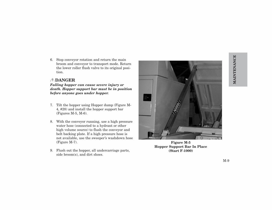
6. Stop conveyor rotation and return the mainbroom and conveyor to transport mode. Returnthe lower roller flush valve to its original posi-tion.
DANGERFalling hopper can cause severe injury ordeath. Hopper support bar must be in positionbefore anyone goes under hopper.
7. Tilt the hopper using Hopper dump (Figure M-4, #28) and install the hopper support bar(Figures M-5, M-6).
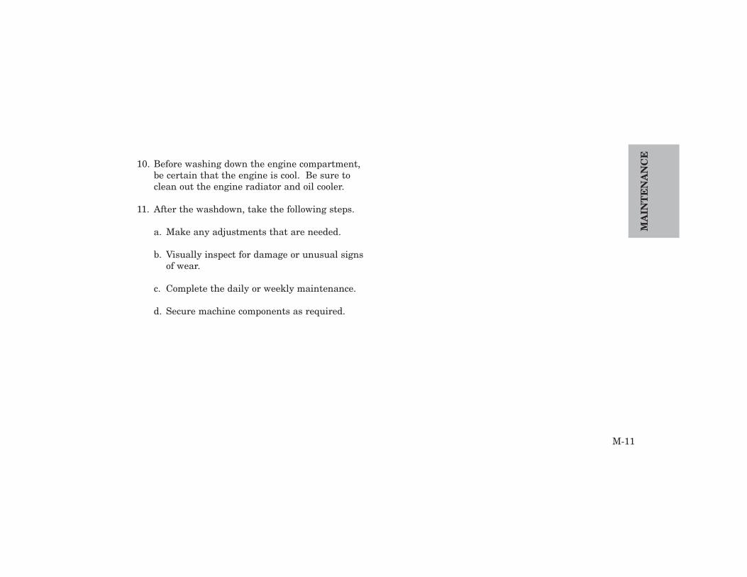
8. With the conveyor running, use a high pressurewater hose (connected to a hydrant or otherhigh volume source) to flush the conveyor andbelt backing plate. If a high pressure hose isnot available, use the sweeper’s washdown hose(Figure M-7).
9. Flush out the hopper, all undercarriage parts,side broom(s), and dirt shoes.
!
Figure M-5Hopper Support Bar In Place
(Start F-1000)
MA
INT
EN
AN
CE
M-10
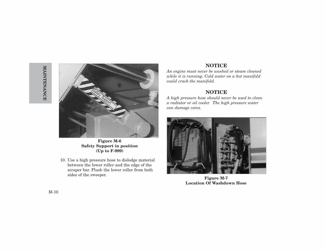
10. Use a high pressure hose to dislodge materialbetween the lower roller and the edge of thescraper bar. Flush the lower roller from bothsides of the sweeper.
NOTICEAn engine must never be washed or steam cleanedwhile it is running. Cold water on a hot manifoldcould crack the manifold.
NOTICEA high pressure hose should never be used to cleana radiator or oil cooler. The high pressure watercan damage cores.
Figure M-7Location Of Washdown Hose
Figure M-6Safety Support in position
(Up to F-999)
10. Before washing down the engine compartment,be certain that the engine is cool. Be sure toclean out the engine radiator and oil cooler.
11. After the washdown, take the following steps.
a. Make any adjustments that are needed.
b. Visually inspect for damage or unusual signsof wear.
c. Complete the daily or weekly maintenance.
d. Secure machine components as required.
M-11
MA
INT
EN
AN
CE

MA
INT
EN
AN
CE
M-12
TOWING
Elgin Sweeper Company recommends that all tow-ing be performed by a professional towing service.The following procedure is provided in the eventthat the Eagle must be towed by other than a tow-ing service.
In all cases the procedure below must be followed,proper equipment must be used and all laws apply-ing to vehicles in tow must be obeyed.
CAUTIONMaximum towing speed must not exceed 55mph (90 km/h).
NOTICETo avoid damage when towing the Eagle, follow alltowing instructions in the truck operator’s manual.
If the Eagle can be steered, it can be towed fromthe front with all wheels on the ground. If thesweeper must be towed, proceed as follows.
WARNINGSteering will NOT have power assist.
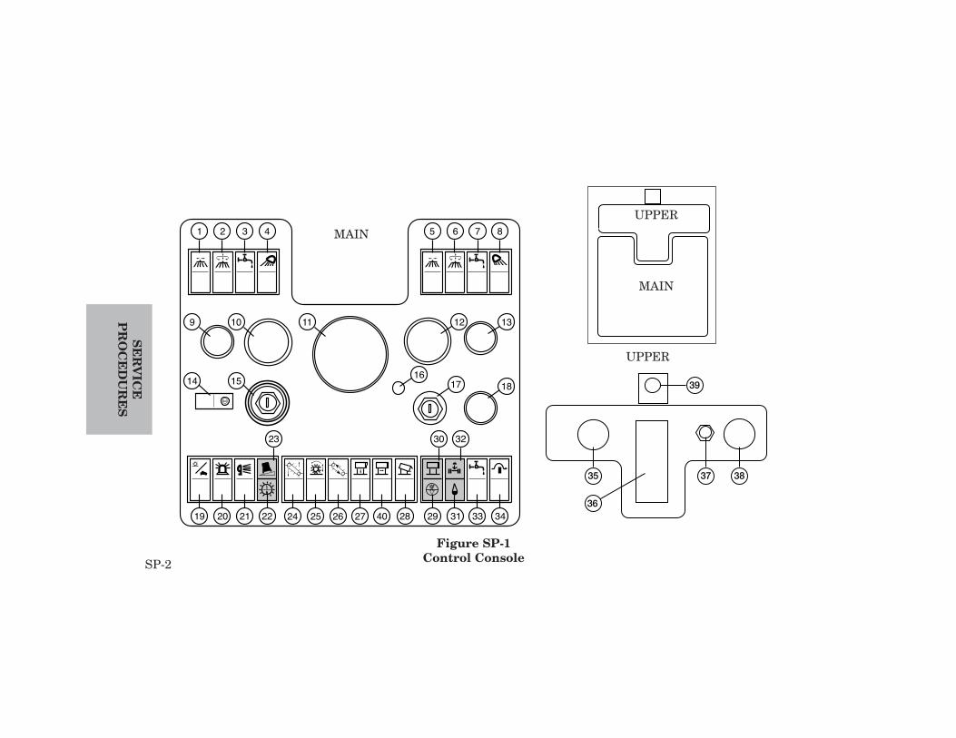
1. Raise all sweeping components to the transportposition, using Side Broom In / Out (right #5,left - #1), Side Broom Rotation / Up / Down(Figure SP-1, right - #6, left - #2), Main BroomRotation / Up / Down (#25) and Conveyor Up /Down (#24).
!
!
SP-1
SE
RV
ICE
PR
OC
ED
UR
ES
SERVICE PROCEDURESGeneral service procedures are provided in this chapter for simple and routine service. For detailed serviceprocedures, see the Eagle Service Manual.
SE
RV
ICE
PR
OC
ED
UR
ES
SP-2
1 2 3 4
9
14 15
10 11 1312
181716
23 30 32
19 20 21 22 24 4025 26 27 28 29 31 33 34
5 6 7 8
Figure SP-1Control Console
35 37 38
39
36
UPPER
MAIN
MAIN
UPPER

2. Set Sweep/Transport Circuit Select (#19) totransport. Air springs will automatically raisethe sweeper when the sweeper is switched totransport mode, provided there is air pressure.
3. Set parking brake.
4. Check all components for adequate road clear-ance. If necessary, chain up or remove the cen-terboard, dirt shoes and any other componentthat might be too low to the ground.
5. Block the wheels.
6. Disconnect the propeller shaft at the rear axle,and secure the shaft to the frame or a crossmember.
7. If damage to the rear axle is suspected, removethe axle shafts and cover hub openings to pre-vent dirt contamination or loss of lubricant.
8. Connect the towing vehicle to a main structuralpart of the sweeper. Do not connect to abumper. Use tow bar and safety chain system.
9. Unblock the wheels.
NOTICEIf the sweeper has air brakes and the air supply hasbeen exhausted, the brakes will lock and will needto be released.
After towing is completed, proceed as follows:
1. Block the wheels securely BEFORE disconnect-ing the sweeper from the towing vehicle.
2. Install the propeller shaft.
3. If axle shafts were removed before towing,uncover hub openings and install the axleshafts.
4. Check for proper phasing of the universaljoints.
5. Check sweeper position to make sure it will notroll and unblock the wheels.
SP-3
SE
RV
ICE
PR
OC
ED
UR
ES
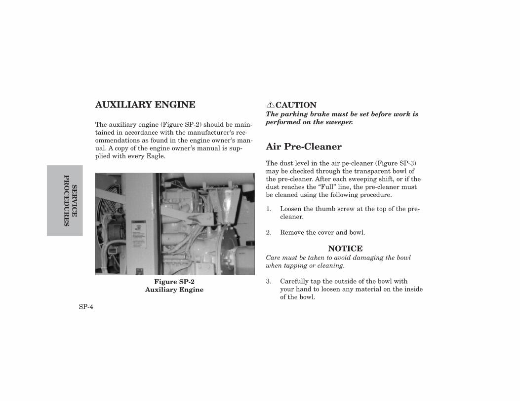
AUXILIARY ENGINE
The auxiliary engine (Figure SP-2) should be main-tained in accordance with the manufacturer’s rec-ommendations as found in the engine owner’s man-ual. A copy of the engine owner’s manual is sup-plied with every Eagle.
CAUTIONThe parking brake must be set before work isperformed on the sweeper.
Air Pre-Cleaner
The dust level in the air pe-cleaner (Figure SP-3)may be checked through the transparent bowl ofthe pre-cleaner. After each sweeping shift, or if thedust reaches the “Full” line, the pre-cleaner mustbe cleaned using the following procedure.
1. Loosen the thumb screw at the top of the pre-cleaner.
2. Remove the cover and bowl.
NOTICECare must be taken to avoid damaging the bowlwhen tapping or cleaning.
3. Carefully tap the outside of the bowl withyour hand to loosen any material on the insideof the bowl.
!
SE
RV
ICE
PR
OC
ED
UR
ES
SP-4
Figure SP-2Auxiliary Engine

4. Dump the contents of the bowl and wipe theinside of the bowl. The bowl may be washedusing a non-sudsing detergent, such as dish-washer liquid, and water. Bowl must be com-pletely dry before reinstallation.
5. Reinstall the bowl with the “Full” line posi-tioned so that it is easily visible.
6. Reinstall the cover and secure the bowl andcover in place with the thumb screw.
Air Cleaner
The engine is equipped with a dual-element, dry-type air cleaner with an automatic rubber dumpvalve (Figure SP-4).
A sensor in the air cleaner signals when air flow isrestricted, causing the Air Filter RestrictionIndicator (Figure SP-1, #29) to light on the controlpanel. This indication alerts the operator that theair filter needs servicing.
To inspect the air filter, use the following proce-dure:
1. Remove the center retaining bar from the filtercanister, then remove the canister cover.
2. Remove the outer element.
SP-5
SE
RV
ICE
PR
OC
ED
UR
ES
Figure SP-3Air Pre-cleaner

NOTICEA dirty outer element should be discarded, notcleaned for further use. Cleaning an element voidsthe warranty and makes the element less effective.
3. If the outer element is dirty, replace it with anew one.
NOTICEA loose, damaged or missing seal will allow dust toclog the inner element.
4. Check the rubber seal on the open end of theouter element. If the seal is loose, damaged ormissing, replace the element with a new one.
NOTICEIf a new outer element must be installed, a newinner element must also be installed.
5. Visually inspect the inner element while it isin the canister. If the inner element is dirty,remove it and install a new one. The inner ele-ment cannot be cleaned.
6. Visually check the rubber dump valve andpinch the lips of the valve to remove any accu-mulation of debris.
7. Before installing a new or cleaned element,clean the inside of the air cleaner canister witha damp, lint-free cloth.
SE
RV
ICE
PR
OC
ED
UR
ES
SP-6
Figure SP-4Air Cleaner
8. Install the outer element.
9. Secure the element with the retaining bar,making sure the bar is in the correct position.
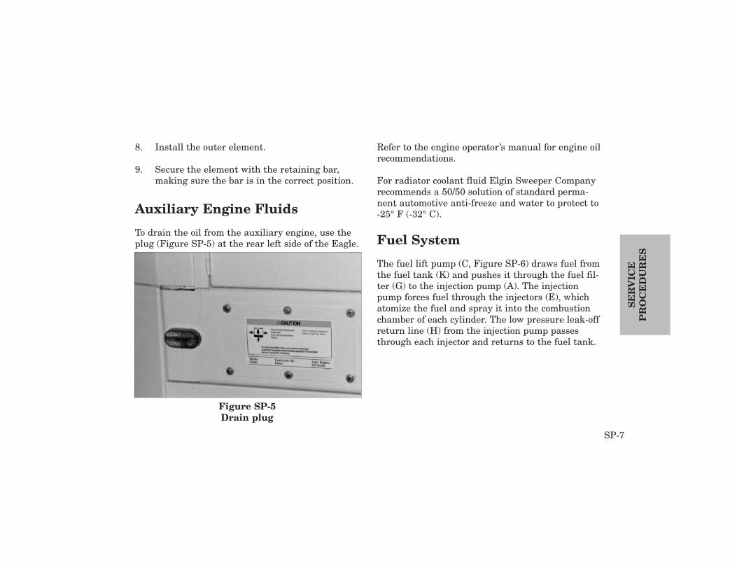
Auxiliary Engine Fluids
To drain the oil from the auxiliary engine, use theplug (Figure SP-5) at the rear left side of the Eagle.
Refer to the engine operator’s manual for engine oilrecommendations.
For radiator coolant fluid Elgin Sweeper Companyrecommends a 50/50 solution of standard perma-nent automotive anti-freeze and water to protect to-25° F (-32° C).
Fuel System
The fuel lift pump (C, Figure SP-6) draws fuel fromthe fuel tank (K) and pushes it through the fuel fil-ter (G) to the injection pump (A). The injectionpump forces fuel through the injectors (E), whichatomize the fuel and spray it into the combustionchamber of each cylinder. The low pressure leak-offreturn line (H) from the injection pump passesthrough each injector and returns to the fuel tank.
SP-7
SE
RV
ICE
PR
OC
ED
UR
ES
Figure SP-5Drain plug
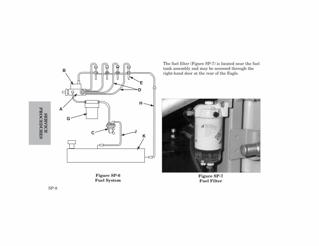
The fuel filter (Figure SP-7) is located near the fueltank assembly and may be accessed through theright-hand door at the rear of the Eagle.
SE
RV
ICE
PR
OC
ED
UR
ES
SP-8
Figure SP-6Fuel System
Figure SP-7Fuel Filter

DRAINING THE FUEL WATERSEPARATOR
The water separator on the bottom of the fuel filtershould be checked daily and drained when needed.Frequency of draining will be determined by oper-ating conditions and quality of the fuel.To drain the separator, use the following procedure:
1. Place a container capable of holding at least0.5 pint (0.2 L) at the end of the hose under-neath the drain plug.
2. Loosen the drain plug and air intake plug untilwater begins to flow.
3. Allow the water and any contaminated fuel todrain into a pan.
4. When flow no longer contains water, installand tighten the drain plug and air intake plug.The drain must always be closed before start-ing the engine.
5. Bleed air from the fuel system by following the
instructions in the operator manual suppliedby the manufacturer of the truck engine andauxiliary engine.
6. Start the engine, then make sure that no fuelis leaking from the filter.
NOTICEThe presence of a large amount of water in the filtermay indicate that water should be drained from thefuel tank. If so, the cause of the water build-upshould be found.
CHANGING FUEL FILTER
To change the fuel filter (Figure SP-7), use the fol-lowing procedure:
1. Loosen the spring clamp to remove the filterfrom the filter head.
2. Inspect the filter for water build-up before dis-carding it.
3. Clean the filter sealing surface.
SP-9
SE
RV
ICE
PR
OC
ED
UR
ES

4. Apply a light coat of engine oil to the surface ofthe filter gasket.
5. Install a new filter in the filter head andsecure it with the spring clamp.
6. Bleed the fuel system, using the following pro-cedure.
BLEEDING THE FUEL SYSTEM
Air must be removed from the fuel system after thefuel filter has been changed, other fuel system com-ponents have been serviced or the engine has runout of fuel.
To bleed the fuel system, use the following proce-dure:
1. Loosen the bleed plug on the filter head.
NOTICEIf the hand-operated lift pump lever does not pumpfuel, use the starter to rotate the engine 1/4 turn sothat the cam-actuated lever is not on the high sideof the lobe.
2. Use the lift pump lever to manually operatethe fuel lift pump until no more air bubblesare present in the fuel flowing at the bleedplug. Return the lift pump lever to the storageposition.
3. Tighten the bleed plug.
WARNINGDo not bleed the high pressure lines when theengine is hot. Stand clear of any moving partsor drive belts that could cause injury.
4. Loosen the fittings on the high pressure linesat the four injectors.
!
SE
RV
ICE
PR
OC
ED
UR
ES
SP-10
CAUTIONNever operate the starter for more than 10 sec-onds. Longer operation will lead to an overdischarge of the batteries, as well as starterseizure. Wait at least 30 seconds betweenattempts to start the engine.
5. Operate the starting motor until there is no airin the fuel flowing from the fittings.
6. Tighten the fittings.
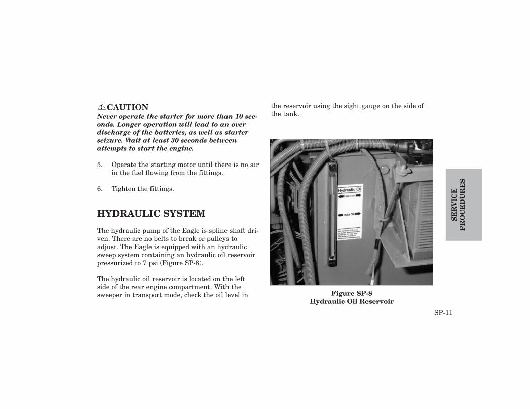
HYDRAULIC SYSTEM
The hydraulic pump of the Eagle is spline shaft dri-ven. There are no belts to break or pulleys toadjust. The Eagle is equipped with an hydraulicsweep system containing an hydraulic oil reservoirpressurized to 7 psi (Figure SP-8).
The hydraulic oil reservoir is located on the leftside of the rear engine compartment. With thesweeper in transport mode, check the oil level in
the reservoir using the sight gauge on the side ofthe tank.
!
SP-11
SE
RV
ICE
PR
OC
ED
UR
ES
Figure SP-8Hydraulic Oil Reservoir

SE
RV
ICE
PR
OC
ED
UR
ES
SP-12
CAUTIONHydraulic reservoir is pressurized to 7 psi.Depressurize before adding oil or changingfilter.
NOTICEElgin Sweeper Company recommends Texaco RandoHDZ 68 or equivalent hydraulic oil...
After every 500 hours of use, or every 6 months,whichever occurs first, the hydraulic oilshould be changed and the tank flushed. Oilmust be new, clean oil and meet all Elginrequirements for hydraulic oil.
When adding oil, remove the hex head plug on thetop of the return filter and add oil. This will pre-filter the oil added to the tank.
Used hydraulic filter elements should be replacedwith new, clean filters per scheduled maintenanceor when indicated by the Hydraulic FilterRestriction indicator (Figure SP-1, #22). Neverreuse a filter.
To drain oil from the hydraulic oil reservoir, use theplug at the left side of the rear of the sweeper.
! SPRAY WATER SYSTEM
Water applied during sweeping through spray noz-zles (Figure SP-9) suppresses dust and moistensthe debris for better settling in the hopper.
Two interconnected 140 gal. (529.8 L) (total of 280gal. [1060 L]) polyethylene water tanks (Figure SP-10) supply water for the spray water system.
Figure SP-9Side Broom

Three spray nozzles are located at each side broomand at the main broom. An optional front spray baris available.
A fill hose is stored in the right side of the rearengine compartment. Before filling the watertank(s), always allow the hydrant to run to flushout any sediment or debris in the hydrant.
The No Spray Water Indicator (Figure SP-1, #31)will light when the spray water tanks are emptyand must be refilled.
Water for the spray water system passes through a100 mesh filter prior to entering the water pump.This stainless steel strainer filter is located behindthe rear right hand side panel and should becleaned daily.
To clean the water filter strainer, use the followingprocedure:
1. Close the manual shutoff valve (Figure SP-11)located between the water filter and the watertank.
2. Unscrew the water filter housing from the filterhead and remove the strainer.
3. If the strainer needs cleaning, open the shutoffvalve and flush the screen with water, thenclose the valve.
4. Install the strainer and screw the water filterhousing back into the filter head.
SP-13
SE
RV
ICE
PR
OC
ED
UR
ES
Figure SP-10Top Of Spray Water Tank

5. Turn on the shutoff valve.
The filter should be changed only if it has beendamaged.
SWEEPING PATTERNS
Broom sweeping patterns are a guideline of sweep-ing performance. Patterns should be checked daily
according to the procedure in the OperationsSection of this manual.
If the patterns do not conform to those shown inthe Operations Sections, the following proceduresshould be performed to correct the pattern.
Side Broom Adjustment
SIDE-TO-SIDE ANGLE
For most sweeping conditions, the side-to-sideangle of the side broom(s) should be 5°. For severe-ly angled gutters, a larger angle may be requiredfor optimum sweeping performance.
To correct the side broom pattern, if it does not reg-ister 5° side-to-side angle on the protractor, use thefollowing procedure:
SE
RV
ICE
PR
OC
ED
UR
ES
SP-14
Figure SP-11Side Broom Spray Water Shutoff Valve

1. Park the sweeper on a level, paved area.
2. Start the auxiliary engine.
3. Lower the side brooms to the sweeping posi-tion using Side Broom In / Out (right #5, left -#1), Side Broom Rotation / Up / Down (FigureSP-1, right - #6, left - #2).
4. Turn off auxiliary engine.
5. Turn key to ON without starting engine.
6. Place a protractor on the side broom disc andperpendicular to the side of the sweeper.
7. If the angle is incorrect, loosen the two boltssecuring the motor bracket. Tilt the broom tothe desired angle and tighten the two bolts.
8. Start auxiliary engine.
9. Retract brooms using Side Broom In / Out(right #5, left - #1), Side Broom Rotation / Up /Down (Figure SP-1, right - #6, left - #2).
10. Stop auxiliary engine.
NOTICEThis setting will require additional adjustmentwhen sweeping areas with deep gutters. Best resultsare obtained by setting the broom contact pattern atthe location with the unusual gutter configuration.
FRONT-TO-BACK ANGLE
To correct the side broom pattern, if it does not reg-ister 5° (or desired) front-to-back angle on the pro-tractor:
1. Park the sweeper on a level, paved area.
2. Start the auxiliary engine.
3. Lower the side brooms to the sweeping posi-tion using Side Broom In / Out (right #5, left -#1), Side Broom Rotation / Up / Down (FigureSP-1, right - #6, left - #2).
4. Turn off auxiliary engine.
SP-15
SE
RV
ICE
PR
OC
ED
UR
ES

5. Turn key to ON without starting engine.
6. Place a protractor on the side broom disc andparallel to the side plate of the sweeper.
7. Loosen the jam nut on the turnbuckle (FigureSP-12).
8. Turn the turnbuckle to set the broom at thedesired angle.
9. When the broom angle is properly set, tightenthe jam nut on the turnbuckle.
8. Start auxiliary engine.
9. Retract brooms using Side Broom In / Out(right #5, left - #1), Side Broom Rotation / Up /Down (Figure SP-1, right - #6, left - #2).
10. Stop auxiliary engine.
DOWN PRESSURE
Adjusting the down pressure at a side broom willchange the size of the broom pattern. More downpressure makes a larger pattern. To correct sidebroom downpressure, use the Side Broom PressureRegulator (Figure SP-1, #9) located on the controlconsole.
CAUTIONRotating broom can cause personal injury. Donot touch or step on side broom.
!
SE
RV
ICE
PR
OC
ED
UR
ES
SP-16
Figure SP-12Side Broom Turnbuckle

Main Broom Adjustment
To adjust the main broom contact area, use theMain Broom Pressure Regulator located on theControl Console (Figure SP-1, #18).
DIRT SHOE ADJUSTMENT
Dirt shoes (Figure SP-13) ride perpendicular to theground to act as a guide to keep debris between themain broom and the conveyor.
The main broom rotates between the two dirtshoes. Wings at the rear of each dirt shoe assurethat the bristles are turned in and ride flush with-in the dirt shoe housings.
Both dirt shoes should be correctly aligned andride level with the surface of the road. If incorrect-ly aligned, the rubber will wear unevenly. If theyare not correctly positioned, this should be correct-ed immediately.
To check for proper dirt shoe adjustment:
1. Lower the conveyor using Conveyor Up / Down(Figure SP-1, #24).
2. Lower main broom and start rotation using MainBroom Up / Down / Rotate (Figure SP-1, #25).
SP-17
SE
RV
ICE
PR
OC
ED
UR
ES
Figure SP-13Dirt Shoe
WARNINGContact with moving parts of main broomdrive can cause severe injury. Do not attemptrepairs with engine running.
3. Drive the sweeper forward to allow brooms toattain proper sweeping position.
4. Visually inspect the rotation of the main broombetween the dirt shoes.
The ground clearance of the dirt shoes duringtransport is set by the airbags. Dirt shoe groundclearance should be approximately 8 inches (30cm).
If the transport position of the dirt shoes is not 8inches:
1. Adjust the lift pin roller to the bottom of theslot at the center of the tow bar weldment.
2. Adjust the arm bracket to level the dirt shoe.
3. Check the pivot to ensure that it is not binding.
An improperly adjusted dirt shoe may cause theshoe to nose dive during transport.
DIRT DEFLECTOR
A centerboard dirt deflector runs under the centerof the Eagle between the side brooms and mainbroom. The deflector provides better sweeping bypreventing material swept by the side brooms frombeing thrown beyond the reach of the main broom.Adjusting chains are used to keep the deflector inthe proper position with the rubber portion in con-tact with the street while in sweeping mode.The dirt deflector should be inspected regularly andchanged if damaged or worn.
!
SE
RV
ICE
PR
OC
ED
UR
ES
SP-18
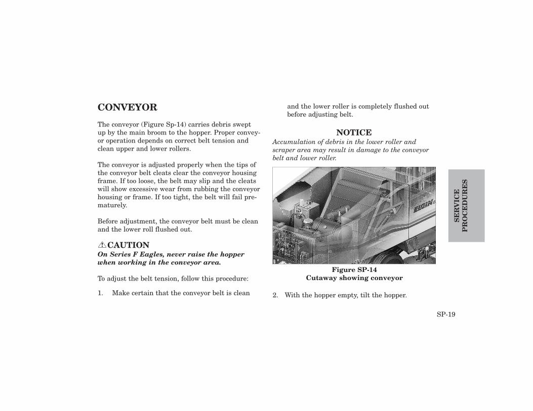
CONVEYOR
The conveyor (Figure Sp-14) carries debris sweptup by the main broom to the hopper. Proper convey-or operation depends on correct belt tension andclean upper and lower rollers.
The conveyor is adjusted properly when the tips ofthe conveyor belt cleats clear the conveyor housingframe. If too loose, the belt may slip and the cleatswill show excessive wear from rubbing the conveyorhousing or frame. If too tight, the belt will fail pre-maturely.
Before adjustment, the conveyor belt must be cleanand the lower roll flushed out.
CAUTIONOn Series F Eagles, never raise the hopperwhen working in the conveyor area.
To adjust the belt tension, follow this procedure:
1. Make certain that the conveyor belt is clean
and the lower roller is completely flushed outbefore adjusting belt.
NOTICEAccumulation of debris in the lower roller andscraper area may result in damage to the conveyorbelt and lower roller.
2. With the hopper empty, tilt the hopper.
!
SP-19
SE
RV
ICE
PR
OC
ED
UR
ES
Figure SP-14Cutaway showing conveyor

3. Place the hopper support bar (Figure SP-15. 16)into proper position. Avoid contact with truckexhaust pipe.
DANGERFalling hopper can cause severe injury ordeath. Hopper support bar must be in placebefore working under the hopper.
CAUTIONStanding or climbing on truck frame may bedangerous. Use caution. Do not step on sidebroom disks.
4. Lower the conveyor to sweep position using theConveyor Up / Down switch (Figure SP-1, #24).
5. Loosen the jam nuts (Figure SP-17) and turnthe adjustment nuts on both sides of the upperconveyor assembly. Counterclockwise willincrease tension. Clockwise will decrease ten-sion.
!
!
SE
RV
ICE
PR
OC
ED
UR
ES
SP-20
Figure SP-15Hopper Support Bar In Place
(Start F-1000)

NOTICEUse small adjustments (no more than 1/4 turn).Run the belt for several minutes with an enginespeed of 1800 rpm to check results before makingany additional adjustments.
6. If belt runs to the left (as viewed facing towardthe front of the (sweeper), increase tension onthe left side. Then decrease tension an equalamount on the right side.
SP-21
SE
RV
ICE
PR
OC
ED
UR
ES
Figure SP-16Safety Support In Place
(Up to F-999)
Figure SP-17Upper Conveyor Assembly
Adjustment Nut

7. When adjustment is complete, tighten the jamnuts.
8. Return conveyor to transport position usingConveyor Up / Down switch (Figure SP-1, #24).
9. Lower the safety support.
10. Return the hopper to transport position.
DAILY WASHDOWN
A very important step in sweeper maintenance is awashdown after each run. Use the following proce-dure in washing the sweeper.
NOTICEWash down the machine after every sweeping shift.
1. Park the sweeper on a level surface.
2. Lower conveyor and start rotation usingConveyor Up / Down (Figure SP-1, #24) andConveyor Rotate (#26).
3. Lower the main broom using Main Broom Up /Down / Rotate (Figure SP-1, #25)
4. Fill the water tank until it overflows, allowingthe water to flush the conveyor belt. This will
SE
RV
ICE
PR
OC
ED
UR
ES
SP-22
Figure SP-18Lower Roller Flush Valve

remove heavy material from the conveyor andconveyor deflectors. Turn on the lower rollerflush valve (Figure SP-18), located below thewashdown hose quick disconnect coupling.
5. Periodically reverse the conveyor (for no morethan 30 seconds) to dislodge material betweenthe lower roller and the edge of the scraper bar.
6. Stop conveyor rotation and return the main broomand conveyor to transport mode. Return the lowerroller flush valve to its original position.
DANGERFalling hopper can cause severe injury ordeath. Safety Support must be in positionbefore anyone goes under hopper.
7. Tilt the hopper using Hopper dump (Figure SP-1,#28) and install the Safety Support bar (FigureSP-15, 16).
8. With the conveyor running, use a high pressurewater hose (connected to a hydrant or otherhigh volume source) to flush the conveyor and
belt backing plate. If a high pressure hose isnot available, use the sweeper’s washdown hose(Figure SP-19).
9. Flush out the hopper, all undercarriage parts,side broom(s), and dirt shoes.
10. Use a high pressure hose to dislodge materialbetween the lower roller and the edge of thescraper bar. Flush the lower roller from bothsides of the sweeper.
!
SP-23
SE
RV
ICE
PR
OC
ED
UR
ES
Figure SP-19Location Of Washdown Hose
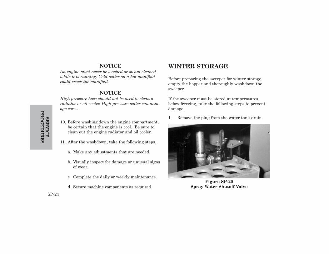
NOTICEAn engine must never be washed or steam cleanedwhile it is running. Cold water on a hot manifoldcould crack the manifold.
NOTICEHigh pressure hose should not be used to clean aradiator or oil cooler. High pressure water can dam-age cores.
10. Before washing down the engine compartment,be certain that the engine is cool. Be sure toclean out the engine radiator and oil cooler.
11. After the washdown, take the following steps.
a. Make any adjustments that are needed.
b. Visually inspect for damage or unusual signsof wear.
c. Complete the daily or weekly maintenance.
d. Secure machine components as required.
WINTER STORAGE
Before preparing the sweeper for winter storage,empty the hopper and thoroughly washdown thesweeper.
If the sweeper must be stored at temperaturesbelow freezing, take the following steps to preventdamage:
1. Remove the plug from the water tank drain.SE
RV
ICE
PR
OC
ED
UR
ES
SP-24
Figure SP-20Spray Water Shutoff Valve

2. Open the spray water shutoff valve (FigureSP-20) and remove the water filter (Figure SP-21). Empty the filter body and store it in thecab.
3. Make sure that the cooling system of theengine has antifreeze concentrations adequateto prevent freezing.
4. Drain the fuel water separator.
5. Open the drain on the lower section of thespray water pump (Figure SP-22).
6. If water is being used instead of solvent in thewindshield washer, drain the washer solventbottle, which is under the left-hand operator’sseat.
SP-25
SE
RV
ICE
PR
OC
ED
UR
ES
Figure SP-21Water Filter
Figure SP-22Water Pump
Follow all recommendations of the engine manufac-turer for cold weather storage.
In addition, whenever the engine is to be stored forseveral months or more, follow the engine manufac-turer’s recommendations to minimize corrosion anddeterioration.
The following steps may need to be taken for long-term storage.
1. Change engine oil and replace oil filter. Usedoil will not give adequate protection.
2. Inspect and, if necessary, replace the air filter.
3. Drain and flush the cooling system, if theengine will be stored for a year or more.
4. Make the following additions of inhibitor. Sealeach opening immediately after addinginhibitor to prevent inhibitor from changing togas.
a. Drain fuel tank and add 1 oz. (30 ml) ofinhibitor per 4 gal. (15L) of tank capacity.
b. Add 1 oz. (30 ml) of inhibitor to crankcasefor each quart (0.95 L) of crankcase oil.
c. Disconnect air intake piping from the man-ifold. Pour 3 oz. (90 ml) of inhibitor intointake system and reconnect the piping.
5. After all inhibitor additions are completed,crank the engine several revolutions with thestarter (do not allow the engine to start).
6. Loosen fan and alternator belts to relieve ten-sion. Remove belts if desired.
CAUTIONGas given off by batteries is explosive. Keepsparks and flames away from battery. Alwaysuse a voltmeter or hydrometer to check batterycharge. Always remove grounded (-) batteryclamp first and replace it last.
!
SE
RV
ICE
PR
OC
ED
UR
ES
SP-26
7. Remove and clean battery. Store in a cool, dryplace and keep fully charged.
8. Clean the exterior of the equipment and touch-up any scratched or chipped painted surfaces.
9. Seal all openings on engine with plastic bagsand tape.
10. Coat all exposed metal surfaces with grease orcorrosion inhibitor.
SPRING START-UP
Follow all directions of the engine manufacturer forstart-up of equipment.
1. Remove all protective coverings, includingthose on engine and electrical systems.
2. Install fan and alternator belts, if they wereremoved. Inspect belts and replace them if they show cracks, stretching or fraying. Adjustbelts to their proper tension.
CAUTIONGas given off by batteries is explosive. Keepsparks and flames away from battery. Alwaysuse a voltmeter or hydrometer to check batterycharge. Always remove grounded (-) batteryclamp first and replace it last.
3. Remove battery from storage. Install fully-charged battery and connect cables.
4. Install the plug in the water tank drain.
!
SP-27
SE
RV
ICE
PR
OC
ED
UR
ES

5. Close the spray water shutoff valve (FigureSP-20) and replace the water filter (Figure SP-21).
6. Install the drain plug in the lower section ofthe spray water pump (Figure SP-22).
7. If the windshield washer bottle was emptied,fill it with water or solvent solution.
8. Follow all instructions in the Start-upChecklist at the beginning of the Operationsection of this manual.
SE
RV
ICE
PR
OC
ED
UR
ES
SP-28
More complete troubleshooting and service proce-dures may be found in the Service Manual for theEagle. The troubleshooting listed below is meant asa general guide only.
Conveyor jammedReverse the conveyor for no more than 30 sec-onds at a time to dislodge large objects fromthe conveyor.
Conveyor will not raiseMachine not on level ground.Check parking brake is set. Check 40 psi pressure switch above rear airbags.Check 70 psi pressure switch on air manifold.
Backup alarm does not soundCheck continuity in switch. Spool will stick ifdebris gets into it.
Broom(s) wearing too quickly
Decrease down pressure.
Broom(s) rotating too slowlyDecrease down pressure.
Debris thrown back into gutterBroom angle set too flat, adjust angle.
Excessive dustNot enough water. Check spray nozzles forclogs; check water supply level.
Main or side broom(s) will not riseCheck air pressure in sweep system first. Spool in solenoid valve may be stuck or theremay be an open electric circuit.
Main or side broom(s) will not lowerCheck air pressure in sweep system first.Spool in solenoid valve may be stuck or theremay be an open electric circuit.
T-1
TR
OU
BL
E-
SH
OO
TIN
G
TROUBLESHOOTING

TR
OU
BL
ES
HO
OT
ING
T-2
BATTERY
IGNITION SWITCH
RELAY
CIRCUIT BREAKER
CONTROL SWITCH
COMPONENT (LOAD)
CHASSIS GROUND
ALTERNATOR RELAY
STARTER MOTOR
TROUBLESHOOTING - Electrical Sytem
Air bag suspension - System used to pro-vide stability of the rear axle. Can beadjusted for maximum sweeping anddumping performance.
Broom pattern - Marks made on thepavement by the brooms when rotating thebrooms with the sweeper staying in oneplace. The broom pattern is used to deter-mine that the brooms are making propercontact with the street.
Conveyor - Device that carries debrisswept up by the main broom to the hopper.The Eagle patented No-Jam® conveyor hasmolded-in, full width cleats to move largedebris without jamming.
Dirt deflector - Rubber piece mountedunder the chassis to keep debris within thesweeping path. The Eagle is equipped witha centerboard dirt deflector, runningbetween the side broom and main broom.
Dirt shoes - Devices located on the out-sides of the main broom, used to keepdebris between the main broom and con-veyor.
Down pressure - The amount of down-ward pressure of a broom. The greater thedown pressure, the greater the diggingpower, but the more quickly the broomswill wear.
G-1
GL
OS
SA
RY
GLOSSARY

Hopper - An on-board tank for holdingdebris that has been swept up.
Hopper door - A large door that openswhen the hopper is dumped to allow debristo be emptied from the hopper. Hopperdoor must be open prior to tilting the hop-per.
Main broom - A long cylindrical broomrunning under the sweeper, used to directdebris onto the conveyor.
Mast - The lifting mechanism on the EagleF that raises and lowers the hopper fordumping using a chain and rail mecha-nism.
Side broom - Horizontally rotating broomused to direct debris from the gutter to themain broom.
Spray water - Water sprayed on debrisbeing picked up by the sweeper. This waterreduces the amount of dust.
Sweep path - The width of the sweepingarea produced by the brooms duringsweeping.
Taper - The difference in size of the broompattern from one end of the main broom tothe other end. There should be no taper ifthe main broom is properly adjusted.
GL
OS
SA
RY
G-2


Elgin Sweeper CompanySubsidiary of Federal Signal Corporation
1300 W. Bartlett Rd.Elgin, IL 60120847-741-5370
Printed in U.S.A.Copyright 2007 Elgin Sweeper Company P/N 0701480-D
AM
ERICA’S FIRST
WO
RLD’S FIN EST