ea for the business analyst - leanpub
TRANSCRIPT


EA for the Business AnalystDocumenting heterogenous systems with EnterpriseArchitect
Thomas Kilian
This book is for sale at http://leanpub.com/EABA
This version was published on 2016-04-27
This is a Leanpub book. Leanpub empowers authors and publishers with the Lean Publishingprocess. Lean Publishing is the act of publishing an in-progress ebook using lightweight toolsand many iterations to get reader feedback, pivot until you have the right book and buildtraction once you do.
© 2013 - 2016 Thomas Kilian

Contents
Preface . . . . . . . . . . . . . . . . . . . . . . . . . . . . . . . . . . . . . . . . . . . . . i
Copyright and Disclaimer . . . . . . . . . . . . . . . . . . . . . . . . . . . . . . . . . . ii
I Introduction . . . . . . . . . . . . . . . . . . . . . . . . . . . . . . . . . . 1
1. Landmarks . . . . . . . . . . . . . . . . . . . . . . . . . . . . . . . . . . . . . . . . . 21.1 UML . . . . . . . . . . . . . . . . . . . . . . . . . . . . . . . . . . . . . . . . 21.2 Heterogenous IT Landscapes . . . . . . . . . . . . . . . . . . . . . . . . . . . 31.3 Enterprise Architect . . . . . . . . . . . . . . . . . . . . . . . . . . . . . . . . 4
2. A Short Introduction Into UML . . . . . . . . . . . . . . . . . . . . . . . . . . . . . 52.1 Class . . . . . . . . . . . . . . . . . . . . . . . . . . . . . . . . . . . . . . . . 52.2 Object . . . . . . . . . . . . . . . . . . . . . . . . . . . . . . . . . . . . . . . 6
3. Efficient Use of Enterprise Architect . . . . . . . . . . . . . . . . . . . . . . . . . . 73.1 General . . . . . . . . . . . . . . . . . . . . . . . . . . . . . . . . . . . . . . . 73.2 Basic Configuration . . . . . . . . . . . . . . . . . . . . . . . . . . . . . . . . 7
II Reverse Engineering . . . . . . . . . . . . . . . . . . . . . . . . . 9
4. Hardware . . . . . . . . . . . . . . . . . . . . . . . . . . . . . . . . . . . . . . . . . 104.1 Computer Resources . . . . . . . . . . . . . . . . . . . . . . . . . . . . . . . . 10
5. Software . . . . . . . . . . . . . . . . . . . . . . . . . . . . . . . . . . . . . . . . . . 115.1 Operating Systems . . . . . . . . . . . . . . . . . . . . . . . . . . . . . . . . . 115.2 Middleware . . . . . . . . . . . . . . . . . . . . . . . . . . . . . . . . . . . . 12
6. Interfaces . . . . . . . . . . . . . . . . . . . . . . . . . . . . . . . . . . . . . . . . . 13
7. Use Cases . . . . . . . . . . . . . . . . . . . . . . . . . . . . . . . . . . . . . . . . . 147.1 Actors . . . . . . . . . . . . . . . . . . . . . . . . . . . . . . . . . . . . . . . 147.2 Use Cases . . . . . . . . . . . . . . . . . . . . . . . . . . . . . . . . . . . . . 15
8. Behavior . . . . . . . . . . . . . . . . . . . . . . . . . . . . . . . . . . . . . . . . . . 168.1 Collaboration . . . . . . . . . . . . . . . . . . . . . . . . . . . . . . . . . . . 16
9. Requirements . . . . . . . . . . . . . . . . . . . . . . . . . . . . . . . . . . . . . . . 17

CONTENTS
9.1 Requirements Structure . . . . . . . . . . . . . . . . . . . . . . . . . . . . . . 17
III The Second Project . . . . . . . . . . . . . . . . . . . . . . . . . 19
10. Working with Stakeholders . . . . . . . . . . . . . . . . . . . . . . . . . . . . . . . 2010.1 Teach Stakeholders to Read . . . . . . . . . . . . . . . . . . . . . . . . . . . . 20
11. Configuration Management . . . . . . . . . . . . . . . . . . . . . . . . . . . . . . . 21
12. The Meta Model . . . . . . . . . . . . . . . . . . . . . . . . . . . . . . . . . . . . . . 22
Glossary . . . . . . . . . . . . . . . . . . . . . . . . . . . . . . . . . . . . . . . . . . . . 23
Bibliography . . . . . . . . . . . . . . . . . . . . . . . . . . . . . . . . . . . . . . . . . . 27
This Is Not The End . . . . . . . . . . . . . . . . . . . . . . . . . . . . . . . . . . . . . . 28Feedback . . . . . . . . . . . . . . . . . . . . . . . . . . . . . . . . . . . . . . . . . . 28UML . . . . . . . . . . . . . . . . . . . . . . . . . . . . . . . . . . . . . . . . . . . . 28Enterprise Architect Forum . . . . . . . . . . . . . . . . . . . . . . . . . . . . . . . . 28Sparx Community . . . . . . . . . . . . . . . . . . . . . . . . . . . . . . . . . . . . . 29

PrefaceSo you’re a business analyst that dropped into the task to document some large system. Likely inthe order to have a base for improving the existing systems. And probably some legacy systemsneed documentation at all. You’re looking for Ariadne’s thread to effectively solve your task?Here it is!
This book will give a recipe how to document heterogenous environments with UML. I am usingthe tool Enterprise Architect¹ for my examples. The method shown is not specifically bound tothat tool. However, I still recommend it as the best tool on the market².
This book starts with a short intro to UML for business analysts and one about heterogenoussystems in general. As basic knowledge of UML is a prerequisite, but can’t taken as granted forall readers, the next chapter gives a short intro into UML. The focus of this book is to enablebusiness analysts to basically document their systems using UML (with Enterprise Architect).So we step from hardware to software and via use cases to requirements. In the end you shouldhave a complete documentation of your system landscape. Each chapter is constructed as tutorialwhich takes you by the hand and leads you to a complete architecture model step by step. It isup to you how deep you dive into the documentation of the single system parts.
This book is under development. The first chapters are so to speak complete but themore you step to the last chapters there are omissions which will be filled with thenext releases of this book.
The examples and tutorials were build with the EA version current at the time of writingthis book, which is V10. Most of it can also be performed with earlier versions of EA. WhereI remembered it, the difference to those earlier versions is explained with footnotes. If youeventually find somethingwhere your version behaves even different: sendme amail. Purchasersof this book will get updates in case Sparx will change menu positions once again, or correct bugswhich currently prevent/obstruct the use of a few features.
¹http://www.sparx.com²Once I called it the one-eyed amongst the blind. But that’s a different story.
i

Copyright and DisclaimerAlso all of the information in this book has been tested by me in many circumstances I can nothold any liability for use of the here presented information³. However, I’d be glad to receive anykind of feedback⁴ to correct future updates of this book which you will receive for free in turn.Having said this, all information presented here is subject to change without notice.
The names of actual companies and products mentioned herein may be the trademarks of theirrespective owners.
³I really loathe writing such legal blurb since it should be obvious. By the way: German law applies! (Does that change anything?)⁴Just send me a mail to [email protected].
ii

I Introduction
In this Part you will find some general instructions about usage of UML and Enterprise Architect.
1

1. LandmarksThis chapter deals with the analysis domain itself. It will give a glance at the spoken languageUML, the IT landscape and tool Enterprise Architect to bring things together.
The thread you will find in this book is likely not the only one you need. You might leave thepath for good reasons. If any of the areas are new to you, don’t walk away too far. You mightget lost. It is a good idea to have a cutting through the whole area before doing so.
1.1 UML
The acronym UML stands for Unified Modeling Language. It is an open standard, defined andpublished by the Object Management Group. A few facts:
• UML is a language like e.g. Chinese• but much easier to learn.• The number of symbols is mainly reduced to
– ovals (use cases),– rectangles (things),– lines (relations between things)– and a few other seldom used icons¹.
• UML can be used for almost anything in the information technology.
UML may well be used to express things outside the IT. Like in any language you can expressthings
• elegantly,• colloquially and• vulgarly.
The rate of understandability must not necessarily be proportional. UML is all about communi-cation – transporting ideas from one person to another. As a rule of thumb the following applies:
• A good text is– hard to create,– will be understood by many people and is therefore– helpful.
• A bad text
¹You will learn a few more elements than the ones mentioned here in the course of working through the tutorials in this book, once you arefamiliar with the basic concepts.
2

Landmarks 3
– will be understood by few people and is therefore– rather useless.
If you want to walk in UML-land it is convenient to speak the language. If you just want toorder a lunch you likely do not need to speak the language fluently. Nor must you know all thevocabulary. But the often you visit that land, the more you want to know. By and by you learnthe language. Simply by practicing it. So your start will be easy as you have to learn only a fewsymbols for the beginning.
In order to read UML you have to learn two technologies. First you will find a name and a prosedescription of model elements. This will tell the reader roughly what the element is all about.Everything (especially in UML) is looked at from a certain perspective. This gives the contextwhere the elements have meaning. If the name is chosen good, it will tell more than half ofits story. The prose description will aid in this process of understanding that thing. The secondimportant technology is that of diagrams. You might already have seen complex UML diagrams– probably pinned up the wall by nerds which do not understand their contents either. But theposter looks impressive. That’s like trying to read a text from Shakespeare where your vocabularyis only enough to read the menu of a restaurant. The beauty of such complex poetry/UML canonly be enjoyed by people speaking the language fluently. Like for natural languages it’s goodto talk UML with a natural speaker. The more you practice, the faster you will learn.
The examples in this book are designed in a way that will help you learn UML the right way:just the parts you need. No Shakespeare. If you’re already a poet yourself you may simply skipthat section.
1.2 Heterogenous IT Landscapes
In most business areas you will find a variety of hard- and software resources which all play apart in the orchestra. If the symphony shall sound nicely and enjoying it is important that youknow where and why which instrument comes into play. A major target of your documentationmust be to identify system components and interfaces, why they exist, which risks are connectedand how to optimize the components and their interfaces.
At the high end you will find mainframes. They are used in banking, sales and reservationsystems. Their main purpose is to treat so-called transactions at very high volumes. A transactionis a business message that results in a number of operations. A transaction is atomic whichmeansthat it either succeeds and all operations are performed or it fails and no side effect has takenplace. Usually those mainframes have dedicated hardware for things which “usual” machinesperform via software. As a business analyst you must not know about all these details, but ifyour documentation shows the interfaces this is a very valuable information. And using UMLit’s a breeze documenting all this hardware.
Documenting the software for these mainframes is a more challenging task. Only in outlyingdistricts object orientation (and thus easy appliance of UML) is being used. E.g. in the militaryarea where Ada is applied. But most of the software is COBOL, a bit FORTRAN and still quitea number of Assembler. All of that not OO. Neither in design nor in implementation. However,

Landmarks 4
UML is a language for (mostly) technical purposes. And thus it is able to describe also non-OO software. When we go into detail later, you will see that there is quite a large amount ofmainframe software you can also describe OO-based.
Since mainframe terminology is not that common any more I will emphasize some of the termscoming from that world. If you don’t need it in your current project then just stow it away fora later one.
Databases on mainframes would be a chapter on their own. So this book will only tangent them.You might need to dive into that matter separately as you need to document data-warehousing.
In the mid-area you will find mainly UNIX and Windows servers. Most of them are used forweb front-ends. From UML perspective those are “good old friends” if you look into software.Hardware is by far more simple compared to mainframe so you will be able to do that en passant.Similarly this applies to end-user devices like desktops and laptops.
Besides the usual peripherals such as printers, scanners or plotters you might eventually finddedicated hardware. Again, you would only need to document the interfaces here. Detaileddesign would likely require special skill and languages like SysML.
Finally there is the important part of networking. You will need to find ways to describe howthe network looks like, who is involved in terms of being a provider, what data volumes traveland which system is affected by the network.
The whole documentation needs to provide static aspects which show how components aredeployed. This will be the frame for the dynamic view. There are usually a couple of views youneed to document for the different stakeholders involved. The good thing is that UML supportscreation of such views without much hassle. Though it might be a bit tricky to organize them ina way to handle them elegantly.
1.3 Enterprise Architect
Probably you bought this book because you have decided to use Enterprise Architect in favor ofsome other tool. First: I recommend this tool as the best choice amongst all competitors. And ifyou pound in the price, it is really unbeatable. I’m not going to argue pro and con, but be warnedthat EA has some peculiarities we users do not really deserve. EA comes with almost all bellsand whistles one could wish to have for an UML tool. But then it got so fat in the last years thata number of bugs do not get fixed in favor of some other (well, I’d say useless) features. This ismy personal impression – your milage may vary. However, you are invited to join the discussionon their (old-fashioned but very lively) discussion forum².
²http://www.sparxsystems.com/cgi-bin/yabb/YaBB.cgi
2. A Short Introduction Into UMLAs already mentioned UML uses a number of symbols. The whole language is by far morecomplex than shown here in these few chapters. Luckily you do not need to learn it in fulldepth. It is enough to focus on a small selection for a start.
You must not learn the following to know it by heart. Instead you might go back to here in thefollowing text whenever you see one of the here described elements.
2.1 Class
We start with the most famous UML element: a Class. It is something you use in your day-to-daylanguage without even thinking about it. If you say Tree you actually mean the class of trees,be it conifer or broadleaf tree. The same goes for Dog, House, Car, etc. You have implicit picturesof these Classes in your mind. And you can create new Classes by finding similarities betweenthings. So you could build a Class of blue pictures, wooden chairs, food, whatever.
Common to all Classes is that you have a couple of shared Attributes. For the blue picturesyou would have the shade of blue as Attribute rather than the color. Further you might havethe material (linen, wood, etc.) and the artist as Attributes.
Classes can have Methods. This concept is a bit harder to understand. Especially if you comefrom a classical programming approach. The Methods shown with a Class are some piece of codewhich deal with that Class. In object oriented programming you have language constructs thatallow to bundle Attributes and Methods in Classes. Classical programming languages do nothave that out of the box. But with some discipline you can create objects even with COBOL¹. Theprinciple is to use COBOL COPYs for the Attributes and have the procedures (Class Methods)bundled and not sparse over many places.
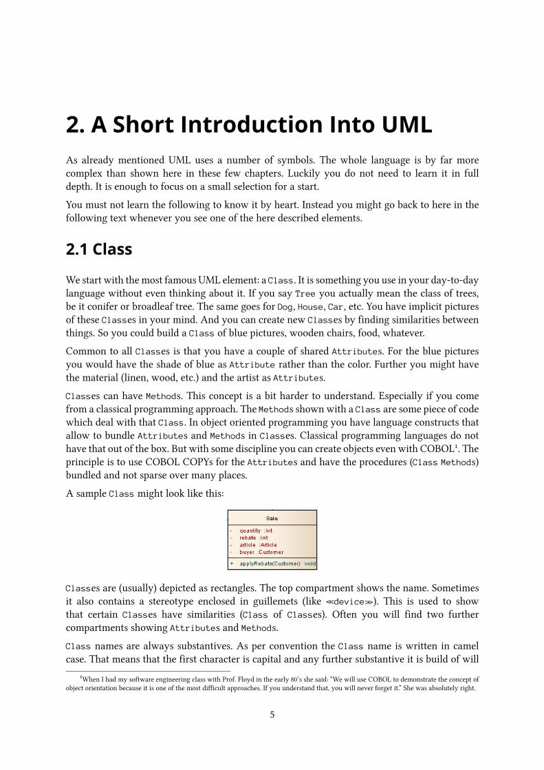
A sample Class might look like this:
Classes are (usually) depicted as rectangles. The top compartment shows the name. Sometimesit also contains a stereotype enclosed in guillemets (like ≪device≫). This is used to showthat certain Classes have similarities (Class of Classes). Often you will find two furthercompartments showing Attributes and Methods.
Class names are always substantives. As per convention the Class name is written in camelcase. That means that the first character is capital and any further substantive it is build of will
¹When I had my software engineering class with Prof. Floyd in the early 80’s she said: “We will use COBOL to demonstrate the concept ofobject orientation because it is one of the most difficult approaches. If you understand that, you will never forget it.” She was absolutely right.
5

A Short Introduction Into UML 6
start with a capital and no space (e.g. CustomerOrder). Attributes and Methods are also writtenin camel case, but they start with a lower case character (like applyRebate in above picture).However, if you have reasons you can deviate from that convention as long as you documentthat with your model.
2.2 Object
Once you understand a Class, an Object is easy. It is a concrete thing formed from a Class. Orvice versa: a Class is the abstraction of an Object. E.g. Dog, House and Car are Classes – abstractthings. But “Bandit”², “My house in A-Street” and “Peter’s Porsche” are concrete Objects.
… omitted …
²Probably Rexx would fit better as name for your dog?

3. Efficient Use of EnterpriseArchitect
You should take a little time to get familiar with the basics of Enterprise Architect (EA). In thischapter I will show some of its concepts and useful hints how to actually work with EA. It willprobably not replace a professional training. But if you are in a hurry yet or simply need somegood advice, you should continue reading. Nevertheless, the following examples are all hands-onand describe exactly what you have to do to get the desired results in Enterprise Architect.
3.1 General
Enterprise Architect is the Swiss Army Knife for the UML modeler. First hand it is an UMLmodeling and communication tool. It differs in the first respect from tools like Visio which areprimarily for drawing pictures. The second aspect is – what I think – the main purpose of thistool. It shall allow you to transport your thoughts to other people and vice versa understandthe thoughts of others. That’s what is called communication. Further you can use EnterpriseArchitect for project documentation, requirements management, project management and acouple of integrative solutions. The major drawback is EA’s user interface, which is not likely towin a design award. You get used to it, but sometimes it simply hurts.
EA holds all model information in a relational database. In its simplest form these are files withEAP extension which are nothing else but Microsoft Access databases. For small modeler groupsit might be sufficient to work shared on such a database. But for medium and larger teams youshould move to a real RDBMS. The chapter Configuration Management elaborates this aspect.
Each model element, Diagram, Relation, Package (and more) is identified with a so-called GUIDwhichmakes it unique all over the universe – at least it’s unlikely to find two different thingswiththe same GUID. Via this identifier it is possible to interchange the contents of single Packagesvia XMI. Such an XMI can be imported in another tool (or another EA instance), manipulated andimported back so you can see the changes. As simple as that sounds as difficult is reality sincerelations will eventually turn the whole story into blood, sweat and tears. More about that inthe chapter Configuration Management. For now you might keep in mind that you can export asingle package, edit this offline and get your work back to the main repository – as long as yourchanges are local to the package!
3.2 Basic Configuration
You open EAP files simply by a double-click on an EAP file or via File/Open Project from insideEA. Further when you start EA it offers a list of recently opened projects. Once a project isopened or a blank one has been created you should make yourself familiar with the GUI. Youcan re-arrange all the docked windows by dragging them to other docked or floating positions.
7

Efficient Use of Enterprise Architect 8
As an EA-power-user-to-be you should configure the layout for a single screen (your laptop) anda second screen (when it’s docked). Here is how it goes: Click-and-drag the title bar of one of thewindows (or a single tab if it is part of a tabbed window) and see that it becomes floating. Whilehovering the floating window watch out for the following icons to appear:
If you drop the floating window over the left one it will be docked at the very left of the mainwindow. Dropping it over one of the compass positions of the cross-formed icon it will dock tothat position of the window where the icon is centered. Dropping it in the middle the floatingwindow will add as tab to the specific window. It takes a bit practice to get familiar with thattechnique but it pays out. It is also possible to make windows auto-hide when they are attachedto one of the main window borders. Just click the little pin-icon right in the header bar (see alsothe Auto-hide in the project browser screenshot below).
My default layout for one screen is this:
Layout of Working Area
Some of these windows are opened with the installation default of EA. Others might needopening from the Viewmenu. For a two-screen configuration use the large screen for the DiagramArea and dock the other windows to one block on the other screen.
… omitted …
II Reverse Engineering
In this part you will learn how to reverse engineer and document heterogenous systems. Startingfrom hardware via software and use cases the journey will end with requirements.
Most UML guides will show how to construct a system starting from requirements throughuse cases and system design to a deployed system. Since a business analyst will often face thesituation where a system is already present and needs some reverse documentation this book istaking the opposite direction. Of course you can go both ways once you reached the end of thisbook and design a system from root to leaf.
9

4. HardwareA common job to be done first place is to describe the overall hardware architecture. There aretwo levels you need to keep in mind. The first level is that which is relevant for an overview,where you want to show which of the many mainframes, UNIX (web-) servers and terminalscommunicate to each other. The second level is the one you need for environment planing. Itcontains details about the single machine and how these are influenced by/are influencing theenvironment. But let’s start with a practical example.
4.1 Computer Resources
Let us assume that we want to document a commercial system. To do so, create an empty EArepository on your local machine. For the very beginning we do not think of configurationmanagement¹ and assume you are a lone worker to document all that stuff. Once you havecreated the repository, rename the root node
so it resembles the company, system or project name. In this example it will be “SomeCommercialSystem”. Now create a View underneath that root node by clicking the Package icon in the projectbrowser (see picture Project Browser above) and name it “Resources”. The reason for doing thisand the next few steps will be explained later. For now just follow them.
Next create a Package inside the View (again click the Package icon with focus on the View) andcall it “Computers”.
You will notice that this time you are asked to create a new Diagram. The name of the Diagram ispredefined by using the Package name, in this case “Computers”. For the type of Diagram selectUML Structural/Deployment. The Diagram is not opened automatically, but it’s already in focus.Just hit enter or double-click it so the blank Diagram will open.
… omitted …
¹Do not allow to get confused by CM aspects at this very moment. The ideal solution would be to have everything ready with the rightconcepts. But that is Utopia. For now it would be ideal if you can sit together with some UML expert, starting to model some concrete things.
10

5. SoftwareThings get more difficult once you have to deal with software. As already mention I’ll put alittle emphasis on the mainframe part since that is even more difficult. You will likely not needto document existent mainframe software in detail as it is generally over-documented. But itoften misses the context and this is where the focus should be set: seeing how the system worktogether andwhich inter-dependencies they have. Often theseminimal viewswork as eye-openerfor many stakeholders.
Since software is quite more complex than hardware (at least from an IT user’s perspective) westart here with the most prominent parts of it: operating systems. From there we will dive intomiddleware and application systems. More details follow in the next section.
5.1 Operating Systems
We will use a similar approach as for the hardware. Create a Package Operating Systems
in the “Resources” Package, again with a Deployment Diagram. Now add three Execution
Environments, namely “z/OS”, “AIX” and “Windows 7”. It should look like this:
These are the operating systems being utilized in our sample environment. Again, these areclasses and not real instances of any deployed OS. These we define right away. Open thecomposite Diagram for “Big Iron” and Ctrl-drag the “z/OS” onto it. Make it a bit larger andfit into the machine node. When you look at the Diagram you should see the following:
Similarly you should repeat the last steps for “Deep Blue”. For the “Web Service” Ctrl-drag the“AIX” as instance of the operating system onto its composite Diagram. With the same scheme
11

Software 12
you can supply the notebooks with their Windows OS. If applicable you can also supply routersand switches with the OS they deploy. It depends on your concrete domain to which level youneed to document hard- and software.
Where it comes to mass-devices like laptops you often want to show quantities. To do so openthe context menu of the according Object and select Advanced/Multiplicity. The followingdialog allows to enter a number or free text which then appears in the top right corner of theelement in the diagram.
5.2 Middleware
The next level is that between operating systems and applications systems: databases andtransaction monitors. Again the scheme is the same as for operating systems. Create threeexecution environments “DB2”, “IMS” and “Oracle” in the “Middleware” Package which itselfis located in the “Resources” Package. Further a “CICS” and a “WebSphere MQ”. That will do forour example.
… omitted …

6. InterfacesThe next step will bring us to Interfaces. Usually these are well (over-) documented and fill acouple of shelfs. It is not necessary to duplicate this information. Instead we make use of themin a condensed format.
Before we get there it is necessary to introduce an UML concept not mentioned before: Ports.They simply mean what the name says. A Port shows some exposed functionality of an element.It is depicted as a small rectangle lying over the border of an element. We make use of such aPort to showhow information is transported from/to an application (protocols: SNA, file transfer,HTTP, etc.) and what information is involved (Interface).
Let us start with creating a new Package “Protocols” in the “Software” View and populate it withsome common protocols. Here you must create a Class Diagram in order to be able to access theright elements. These are Interfaces from the toolbox which are named accordingly. Furtheryou have to change the stereotype to ≪protocol≫ manually. The first time you need to type“protocol” in the Stereotype attribute field. Later you should select that value from the drop down(simply to avoid typos here). Finally it should look like this:
Now we can go ahead and make use of these protocol definitions. We start with the “BusinessManagement” application. Here we will define two Ports. One for a “File Transfer” (e.g. totransfer tax information) and another one with “SNA” that is used for communication with“CICS”.
… omitted …
13

7. Use CasesThis and the following chapter deal with the behavior of the system: first from a user’s view,then from a technical.
You can not understand your system without knowledge of the single Use Cases. They are thereason why all the IT infrastructure was build. Currently you are looking at the system the way:“our system is doing things because some users triggered that behavior”. Your view is IT-centric.By turning the order of the sentence we get: “some users demand a certain functionality whichour system must deliver”. That turns the perspective to the users, the group which finally ispaying for all these services from which they get some value in return. It is quite difficult tomake that turn.
As already mentioned in the UML chapter I recommend to read more in Cockburn andBittner. I will just demonstrate here how to document a Use Case with EA.
To start with Use Cases create a new View called “User Perspective”.
7.1 Actors
Inside the View create a Package “Actors” containing a Use Case Diagram. Here we add just afew Actors assuming these have been identified in longworkshops¹: “Customer”, “TaxAuthority”and “Vendor”.
The above shown are created from the Actor element out of the tool box. The “Tax Authority”has an additional ≪system≫ stereotype. As mentioned before some people have problems seeinga stick man as a system. You can either choose Advanced/Use Rectangular Notation from thecontext menu of “Tax Authority”. In that case you must do that for all single occurrences of thatactor in any Diagram. Or you create a Class stereotyped ≪system actor≫ which will alwaysappear as rectangle. To create a class in a Use Case Diagram youmust choose Other/Class/Classfrom the toolbox.
Each Actor must have a unique name. It is normally that of a distinct group – eventually agroup with just one person or system. It is also very important to describe the Actor in the Notes
¹It may sound silly, but identifying Actors is to a high degree non-trivial. Usually you will find more Actors during a Use Case synthesis.
14

Use Cases 15
field. This description should mention the main Use Cases where the Actor is involved. Also itsexpectations to the system should be described.
If you have identified a larger number of Actors it is a good idea to group them using a boundarywhich e.g. is named according to the business area. Probably you will also find hierarchicalgroups of Actors. In that case draw a Generalization from the specialized to the generalActor. E.g. you could have “District Vendors” and “EMEA Vendors” which are specializationsof “Vendor”. Those actors perform the same Use Cases as “Vendor” but eventually have somespecial Use Cases just performed by them.
7.2 Use Cases
Firstly we have to create another Package inside “User Perspective” which is called “Use Cases”.There will definitely be a number of sub-structures for different business domains in your realcase. Just create that structure ahead and place the single Use Cases inside the ‘owning’ domain.You might end up with around a hundred different Use Cases, but you can’t predict that. Itstrongly depends on the system size and the type of business.
Each of the Packages should contain a Use Case Diagram. The higher level Packages should alsocontain either Package or Use Case Diagrams to enable model navigability.
The “User Perspective” shows that “Use Cases” depend on the “Actors”. Just a simple dashedarrow; but an important statement!
… omitted …

8. BehaviorAfter having stepped aside from the pure technical view in the last chapter we now come back totechnics once again. However, I will not dive very deep into this matter as it is very development-centric and also much too complex to be covered here. Nevertheless the basic techniques can wellbe learned and will help you a lot in documenting your system.
As we now have a business view on the system it is possible to start a ‘forward re-engineering’.That means we focus on an already known Use Case and try to figure out what happens inthe system. During this process you will likely detect design flaws in the system which shouldbe tackled in a further step. The model is excellent to document these flaws so architects anddevelopers can step in later.
8.1 Collaboration
In UML-talk a Collaboration is equal to the Realization of a Use Case showing the behaviorof the designed system. And that is exactly what we are going to do.
First we have to create a new Package called “Behavior” inside “Software”. This Package shouldhave the same sub-structure as “User Perspective.Use Cases”. Inside the “Sales” Package createa Collaboration “Retrieve Customer Information”, make it composite, Ctrl-drag the Use Case
with the same name onto it and draw a Realization from the Collaboration to the Use Case.
… omitted …
16
9. RequirementsWe have almost reached the ground – or the top. Depending on the way you are looking at thesystem. When you have added the Requirements, your system documentation will be complete.I can not describe the whole requirements process here but rather try to line out just the basicfacts which then must be adopted individually.
Cross-the-board there are two states for Requirements: not documented and over-documented.Only in few cases you have a good Requirements basis. I will try to show a way to reflect themin EA. But however the documentation state is: without Requirements you can not design ordocument a system.
9.1 Requirements Structure
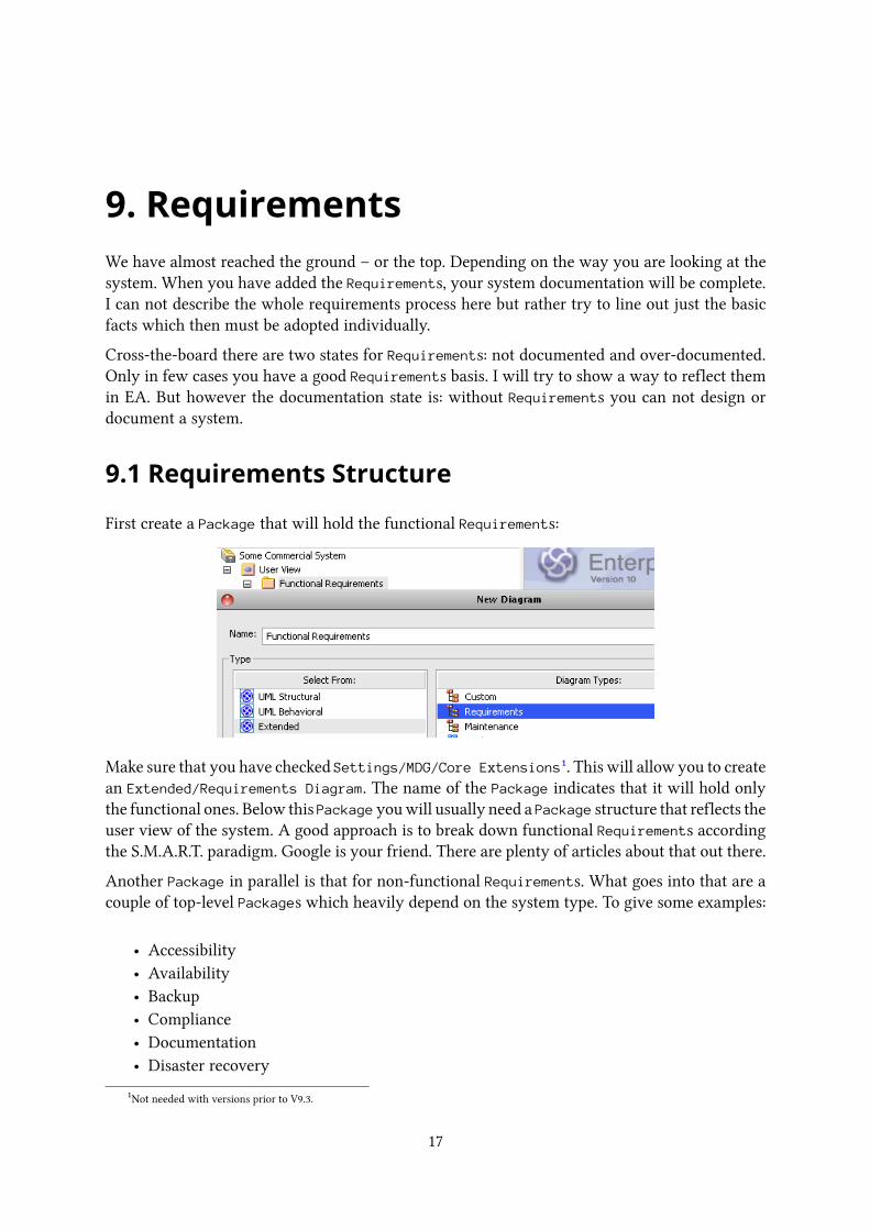
First create a Package that will hold the functional Requirements:
Make sure that you have checked Settings/MDG/Core Extensions¹. This will allow you to createan Extended/Requirements Diagram. The name of the Package indicates that it will hold onlythe functional ones. Below this Package youwill usually need a Package structure that reflects theuser view of the system. A good approach is to break down functional Requirements accordingthe S.M.A.R.T. paradigm. Google is your friend. There are plenty of articles about that out there.
Another Package in parallel is that for non-functional Requirements. What goes into that are acouple of top-level Packages which heavily depend on the system type. To give some examples:
• Accessibility• Availability• Backup• Compliance• Documentation• Disaster recovery
¹Not needed with versions prior to V9.3.
17

Requirements 18
• Legal and licensing issues or patent-infringement-avoidability• Interoperability• Maintainability• Performance / response time (performance engineering)• Platform compatibility• Reliability (e.g. mean time between failures - MTBF)• Reporting• Resilience• Response time• Robustness• Scalability (horizontal, vertical)• Security• Testability
These are just a couple of possible Packages. You might need more or less of them, but at leastsome. The difference between a functional and a non-functional is that the latter is not directlytestable but needs to be judged by a person trained for that specific area (e.g. a lawyer forlegal Requirements). In many cases these non-functional Requirements are by numbers less thanfunctional Requirements. But as verifying them is somuch harder their implication on the systemis much heavier in time and cost.
… omitted …
III The Second Project
In this part you will learn some more advanced techniques. It is called “Second Project” becauseyou should takle these techniques once you have mastered your first project(s) and you aremaking your steps towards being a architect rather than an analyst.
The chapters in this part are under construction and will be extended in the nextreleases of this book.
19

10. Working with StakeholdersOf course you can do a lot of work in your secret chamber to produce a nice model. But it’snot worth a penny if your stakeholder do not understand and/or accept it. I already mentionedwhat communication between modelers means for a model. Even more important is thecommunicationwith stakeholders. There are a couple of ways to establish a good communicationwith them.
10.1 Teach Stakeholders to Read
The ability to read will bring you definite advantages. And reading the same language withouttranslation is the best way to communicate. Surely it depends on the willingness of people tolearn the language. If that is the case then go this way and teach your stakeholders to read UMLmodels in general - and your models in particular.
You probably can tell how talented any of your stakeholders is. Depending on that you maygive them read and eventually write access to your central repository or provide them with anappropriate copy of the repository. If granted the write access they can directly add notes toelements in diagrams. It would even be possible to let them correct parts of the model. But it’srather unlikely that you will find such persons as being a stakeholder in general also means youare conservative. So the best you can expect is to find annotations in the form of notes.
Structure is a key element here. Especially stakeholders need easy entry points where they canfind stuff which is relevant for them. When you initially create the repository structure youshould keep in mind that different stakeholder will see different views of the model. If you cannot layout the package structure accordingly there should be some kind of diagram structure.A possible way to go is to use View/Model Views where you can collect a number of relevantdiagrams. This can be done per user. (Of course not only stakeholder can use this feature.)
… omitted …
20

11. Configuration ManagementAs a business analyst you should usually not need to care about configuration management. Thisis a SEP (somebody else’s problem). However, it’s often good to known what happens behind thescenes. Or you were simply put into the task to configure EA since you anyway work with thetool. As mentioned earlier the tutorials in this book were designed to help yourself and to workstand-alone. But it is very unlikely, though not impossible, to have a project in a complex systemenvironment where you will work as lone analyst.
Generally speaking the configuration management has the task to enable a number of peopleto concurrently work on the same goal with a set of tools. Ideally those tools support thecommunication with team members¹. Again, the real situation can vary in so many parametersthat you can not really give a rule of thumb how to setup an individual environment. ThereforeI will concentrate on two common settings: a group of analysts working on-site and a numberof different groups working at different sites. The best way would be to create a meta-model todocument the needs for configuration management.
… omitted …
¹It sounds a bit like a tautology. But often you find a configuration which merely hinders communication rather than supporting it.
21
12. The Meta ModelMany people are afraid of UML. Even worse with a meta model. It is like pulling yourself up byyour own bootstraps.
You will likely be able to build a meta model only if you are quite firm with UML. However,even if you will not work out a complete meta model (which is good for designing individualprofiles, describing the goals of the overall systems and why it is documented), it is a good ideato place a mini-meta-model in front of your system description¹. This will show how the modelis organized, which modeling rules were applied, etc.
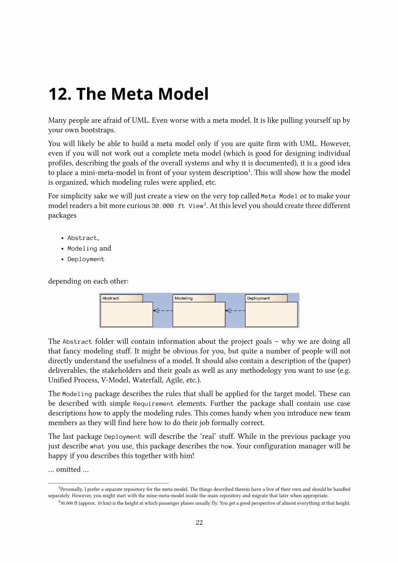
For simplicity sake we will just create a view on the very top called Meta Model or to make yourmodel readers a bit more curious 30.000 ft View². At this level you should create three differentpackages
• Abstract,• Modeling and• Deployment
depending on each other:
The Abstract folder will contain information about the project goals – why we are doing allthat fancy modeling stuff. It might be obvious for you, but quite a number of people will notdirectly understand the usefulness of a model. It should also contain a description of the (paper)deliverables, the stakeholders and their goals as well as any methodology you want to use (e.g.Unified Process, V-Model, Waterfall, Agile, etc.).
The Modeling package describes the rules that shall be applied for the target model. These canbe described with simple Requirement elements. Further the package shall contain use casedescriptions how to apply the modeling rules. This comes handy when you introduce new teammembers as they will find here how to do their job formally correct.
The last package Deployment will describe the ‘real’ stuff. While in the previous package youjust describe what you use, this package describes the how. Your configuration manager will behappy if you describes this together with him!
… omitted …
¹Personally, I prefer a separate repository for the meta-model. The things described therein have a live of their own and should be handledseparately. However, you might start with the mine-meta-model inside the main repository and migrate that later when appropriate.
²30.000 ft (approx. 10 km) is the height at which passenger planes usually fly. You get a good perspective of almost everything at that height.
22

GlossaryActivity Diagram
A → Diagram showing the single steps of a → Use Case scenario.
ActorAn Actor is a person or system which interacts with a system in an→ Use Case. See alsohere.
ActionAn Action is a single step performed in the execution of an → Use Case. see here
AttributeAn Attribute is an UML element which describes an aspect of a Class. See also here.
ArchitectureA logical structure which describes a system such that from requirements over designto deployment each aspect is covered. Each reader (system users, software engineers,requirements mangers, etc.) of an architecture shall be able to easily extract the part thatis relevant for him.
Business ObjectAn → Object that is specifically targeted to some sort of business. A good example is aCustomer Business Object.
CICSAcronym of Customer Information Control System. Used to control the sequence of →transactions on a → mainframe.
ClassA Class is an UML that represents an abstraction of real-world things that are related toeach other. A Class is build from a classification process. A Class usually has different→ Attributes and → Operations. See also here.
CollaborationIn UML it is a means to show how a use case is realized in technical terms. A Collabora-
tion shows the behavior of the system in various facets.
Composite (Diagram)Most UML elements can be made composite. In that case they contain a composite orcontext Diagram which focuses on details of the according element.
ConnectorA visible → Relation between two elements.
23
Glossary 24
Context (Diagram)A synonym for a → Composite Diagram.
DiagramA visual presentation of part of an UML model. It helps the model reader to understand acertain aspect of the model.
Diagram ToolboxA context menu for an UML diagram. It contains a relevant subset of UML elements forthe individual diagram.
EA Acronym of → Enterprise Architect.
Enterprise ArchitectAcronym EA. A tool that supports modeling of UML. Developed by Sparx Systems³,Australia.
FolderIs another word for → Package.
GUIDAcronym for Global Unique IDentifier. A string with hex-chars and dashes which iscreated in a way such that it is very, very unlikely (but not impossible) to see the sameGUID for different elements.
InstanceIs another word for → Object.
IP Acronym for Internet Protocol. A protocol which is used to communicate with distributedcomputers over the Internet.
InternetA network of computers talking to each other via → IP.
LifelineA dashed line showing (a part of) the life of an object in a Sequence Diagram. The topof the line shows the Object name. Elongated rectangles overlaying the dashed line showactivity times. The time vector goes from top to bottom.
MainframeA really huge piece of IT hardware, optimized for maximum transaction throughput andresilience.
MessageAlso Object Message is a piece of information sent from one→ Object to another. Besidesdata it includes an instruction to the receiving Object what kind of action to perform.
³http://www.sparxsystems.com

Glossary 25
MethodA piece of code performing some action. In a → Class the Method usually performs theoperation on → Attributes of the Class. A Method can have parameters and a returnvalue.
MQ Message Queue. An IBM product which allows data exchange on a message basis betweendifferent platforms including mainframes.
ObjectAn Object is a placeholder for a real-world thing. Objects are instantiated from →Classes. Vice versa a Class is an abstraction of Objects. See also here.
Object OrientedA paradigm that sees the world as → Objects abstracted by → Classes with →Attributes and → Methods communicating via → Messages.
OO → Object oriented.
OperationA synonym for → Method.
PackageA Package is an element to structure UML models. … see here
Project BrowserAn EA window which shows the elements of a repository in a tree structure.
Port A means to show exposed behavior of an UML element.
Quick LinkerA tool to connect elements in→EA. Selected elements show a little arrow top right whichcan be dragged to another element or onto a blank space of a→ Diagram in order to createa new element along with a → Connector.
RDBMSAcronym for Relational Database Management System. These systems allow to store andretrieve data fast and on high volumes. Single records can be related to each other via keys.
RelationAn UML concept to tie two elements together. This is expressed through specific →Connectors.
RM Acronym for Requirements Management.
Sequence DiagramA → Diagram showing → Message exchange between → Objects represented by →Lifelines.
Service Oriented ArchitectureAn→ Architecturewhich is focused no services provided over IP. A service correspondsmore or less to a → Transaction or a → Method provided by a → Class. The servicesare described via → WSDL.

Glossary 26
ShakespeareA medieval poet famous for his art to play with words.
StereotypeA grouping characteristic which in → UML is shown as a string enclosed in guillemets(e.g. ≪device≫).
Tagged ValueA means to augment UML elements with extra information. Tagged values come inkey/value pairs. In → EA the value can be a string, a drop down value or a referencesto another element.
TransactionUsually an atomic piece of computation performed on business data.
Use CaseA Use Case is a sequence of Actions triggered by an Actor and return some measurablevalue to that Actor. See also here.
ViewA View in EA is a special form of a → Package.
WSDLAcronym for Web Services Description Language. DescriptionWeb Services DescriptionLanguage WSDL 1.1 document.
UMLAn acronym for Unified Modeling Language. UML is a language standard published bythe Object Modeling Group (OMG). See http://www.omg.org
XMI Acronym for XML Metadata Interchange. Allows to store UML models in XML format fordata interchange. Like UML it is a standard published by the Object Modeling Group(OMG). See http://www.omg.org
XMLAcronym for eXtensible Markup Language. It is defined in the XML 1.0 Specification.

BibliographyBittner, K., Spence, I.: Use Case Modeling. Addison-Wesley Professional, 2002. ISBN-13: 978-0201709131
Cockburn, Alistair: Writing Effective Use Cases. Addison-Wesley Professional, 2000. ISBN-13:978-0201702255
Kilian, Thomas: Inside Enterprise Architect. Leanpub, 2012. https://leanpub.com/InsideEA
Kilian, Thomas: Scripting Enterprise Architect. Leanpub, 2012. https://leanpub.com/ScriptingEA
Linné, Carl von: Systema Naturae. Leiden, 1729.
Object Management Group (eds.): Superstructures 2.4.1, 2011. http://www.omg.org/spec/UML/2.4.1/
Object Management Group (eds.): Business Process Model And Notation (BPMN) Version 2.0,2011. http://www.omg.org/spec/BPMN/2.0/
Sparx Systems: DOORS MDG Link, 2013. http://www.sparxsystems.com/products/mdg/link/doors/purchase.html
Sparx Systems: RaQuest, 2013. http://www.raquest.com
W3C (eds.): XML 1.0 Specification. Internet, 2010. http://www.w3.org
W3C (eds.):Web Services Description Language (WSDL) 1.1. Internet, 2001. http://www.w3.org/TR/wsdl
27

This Is Not The EndI know that the matter described in this book is so complex that only a part of it can be touched. Ineed to be honest: Some chapters in this book might eventually have raised more questions thanyou found answers. This is no cookbook. And the recipes given will not always be tasty. But ifyou got the idea, the golden thread, you made it and you can start asking.
For that reason I would like to add a few links where you will get further help.
Feedback
Any questions you have are important. So you should ask them. Feedback is important for you,me and of course all the other readers. So you are encouraged to contact me at
[email protected]⁴You can mail me directly if you have specific questions, think that something is not clearlydescribed, have detected some error, etc. I’m happy about any kind of feedback.
UML
Getting grips of UML can be a hard one. Superstructure is no bedtime reading. One place whereyou can ask questions is the
http://www.linkedin.com/groups/UML-Lovers-143183/about
You will find quite a number of gurus there which really can help you out.
Enterprise Architect Forum
Probably not necessary to name this source, but anyway:
http://www.sparxsystems.com/cgi-bin/yabb/YaBB.cgi
When you post your questions here you should select the right forum and only post once. Gettinghelp here is most likely the fastest lane you can find. I also post regularly.
Another place is
http://www.linkedin.com/groups/Enterprise-Architect-Sparx-Systems-User-1356/about
Most of the “usual suspects” post in either forums of Sparx and LinkedIn.
⁴mailto:[email protected]
28

This Is Not The End 29
Sparx Community
A not so well known source as Sparx itself does not link this on its forum pages:
http://community.sparxsystems.com
Here you will find a variety of articles and resources around EA.