e5ak operation manual · e5ak iii jhow this manual is organized purpose title description d...
TRANSCRIPT

User's Manual
Cat. No. H088-E1-02
Digital Controller(Programmable Type)

E5AK
I
The E5AK-T is a high-performance programmable digital controller. The E5AK-Tallows the user to carry out the following:
• Set program patterns to each step by time or ramp rise rate• Execute advance, hold and reset step operations• Execute continuous operation of all patterns and repeated operation of same pat-terns
• Check the start of each step or program end time by signals.• Count time from the beginning of each step (time signal)• Select from many types of temperature and analog input (multi-input)• Support position-proportional control (position-proportional type controllers only)• Select output functions such as control output or alarm output (output assign-ment)
•Use the HBA (heater burnout alarm) function (standard type controllers only)•Monitor the control loop by LBA (Loop Break Alarm)•Use the communications function• Calibrate input or transfer output• The E5AK-T also features a watertight construction (NEMA4: equivalent toIP66).This User’s Manual describes how to use the E5AK-T.Before using your E5AK-T thoroughly read and understand this manual in order toensure correct use.Also, store this manual in a safe place so that it can be retrieved whenever neces-sary.
PRECAUTIONS IN USING THE PRODUCTWhen the product is used under the circumstances or environment below, ensureadherence to limitations of the ratings and functions. Also, take countermeasuresfor safety precautions such as fail-safe installations.(1) Use under circumstances or environments which are not described in this user’s manual.(2) Use for nuclear power control, railway, air craft, vehicle, incinerator, medical equipment, enter-
tainment equipment, safety device, etc.(3) Use for applications where death or serious property damage is possible and extensive safety
precautions are required.
About this manual
(1) All rights reserved. No part of this publication may be reproduced, stored in a retrieval system or trans-mitted, in any form, or by any means, mechanical, electronic, photocopying, recording, or otherwise, with-out the prior written permission of OMRON.
(2) Moreover, because OMRON is constantly striving to improve its high-quality products, the information inthis manual is subject to change without notice.
(3) Every precaution has been taken in the preparation of this manual. Nevertheless, if you find any errors oromissions, please contact the branch of OMRON or sales office listed at the end of this manual, and informthem of the catalog No. on the front cover.
Preface

E5AK
II
JMeanings of AbbreviationsSometimes the following abbreviations are used in parameter names, figures and in text ex-planations. These abbreviations mean the following:
Symbol Term
PV Process value
SP (Present) set point *1LBA Loop break alarm
HB Heater burnout
AT Auto-tuning
EU Engineering unit *2
*1 In program pattern diagrams, the present SP is indicated.
*2 _C, m, g and other units are indicated for scaled data. However, “EU” is used as the mini-mum unit for the data. For example, for “50.02 (m)”, 1EU is taken as the minimum unit0.01 (m).
JHow to Read Display SymbolsThe following tables show the correspondence between the symbols displayed on the displaysand alphabet characters.
A B C D E F G H I J K L M
N O P Q R S T U V W X Y Z
J“Reference” markThis mark indicates that extra, useful information follows, such as supplementary explana-tions and how to apply functions.
Conventions Used in This Manual

E5AK
III
JHow This Manual is Organized
Purpose Title Description
D Learning about the gener-al features of the E5AK-T
Chapter 1 INTRODUC-TION
This chapter describes the fea-tures of the E5AK-T, names ofparts, and typical functions.
D Setting up Chapter 2 PREPARA-TIONS
This chapter describes the op-erations that you must carryout (e.g. installation, wiring andswitch settings) before you canuse the E5AK-T.
D Basic E5AK-T operations Chapter 3 BASIC OPERA-TIONChapter 5 PARAMETERS
These chapters describe usingbasic control examples how touse the front panel keys andhow to view the display whensetting the parameters of themajor functions for the E5AK-T.
D Applied E5AK-T opera-tions
Chapter 4 APPLIED OP-ERATIONChapter 5 PARAMETERS
These chapters describes theimportant functions of theE5AK-T and how to use the pa-rameters for making full use ofthe E5AK-T.
D Using a Position-propor-tional type controller
Chapter 4 APPLIED OP-ERATION/4.1 Selecting the ControlMethod
This chapter describes how touse the functions related specifi-cally to position-proportionaltype controllers.
D Communications with ahost computer
Chapter 6 USING THECOMMUNICATIONSFUNCTION
This chapter mainly describeshow to use the communicationscommands, and gives programexamples.
D Calibration Chapter 7 CALIBRATION This chapter describes how theuser should calibrate theE5AK-T.
D Troubleshooting Chapter 8 TROUBLE-SHOOTING
This chapter describes what todo if any problems occur.

E5AK
IV
PRECAUTIONS ON SAFETY
F Marks For Ensuring Safe Use and Their Meanings
This manual uses the following marks to indicate precautions for ensuring that theE5AK-T is used safely.The precautions indicated below describe important information regarding safety.Be sure to follow the instructions described in these precautions.
WARNING Incorrect handling may cause death or injury.
WARNING
Do not touch the terminals while the power isON.This may cause an electric shock.

E5AK
V
NOTICEBe sure to observe these precautions to ensure safe use.
FDo not use the product in places where explosive or flammable gases may be present.
FNever disassemble, repair or modify the product.
FTighten the terminal screws properly.
FUse the specified size of solderless terminals for wiring.
FUse the product within the rated supply voltage.
FUse the product within the rated load.
FThe life expectancy of the output relay varies considerably according to its switching capacityand operating conditions. Be sure to use the output relay within its rated load and electrical lifeexpectancy. If the output relay is used beyond its life expectancy, its contacts may become fused orburned.
F If you remove the controller from its case, never touch nor apply shock to the electronic partsinside.
FDo not cover the E5AK-T. (Ensure sufficient space around the controller to allow heat radiation.)
FDo not use the controller in the following places:
• Places subject to icing, condensation, dust, corrosive gas (especially sulfide gas or ammonia gas).
• Places subject vibration and large shocks.
• Places subject to splashing liquid or oil atmosphere.
• Places subject to intense temperature changes.
• Places subject to heat radiation from a furnace.
FBe sure to wire properly with correct polarity of terminals.
FWhen wiring input or output lines to your controller, keep the following points in mind to reducethe influence from inductive noise:
• Allow adequate space between the high voltage/current power lines and the input/output lines.
• Avoid parallel or common wiring with high voltage sources and power lines carrying large cur-rents.
• Using separating pipes, ducts, and shielded line is also useful in protecting the controller, and itslines from inductive noise.
FCleaning: Do not use paint thinner or organic solvents. Use standard grade alcohol to clean theproduct.
FUse a voltage (100 to 240 VAC at 50 to 60 Hz). At power ON, the prescribed voltage level must beattained within two seconds.
FAllow as much space as possible between the controller and devices that generate a powerful highfrequency (high-frequency welders, high-frequency sewing machines, etc.) or surge. These devicesmay cause malfunctions.
F If there is a large power-generating peripheral device and any of its lines near the controller, at-tach a surge suppressor or noise filter to the device to stop the noise affecting the controller sys-tem. In particular, motors, transformers, solenoids and magnetic coils have an inductance compo-nent, and therefore can generate very strong noise.
FWhen mounting a noise filter on the power supply to the controller, be sure to first check the fil-ter’s voltage and current capacity, and then mount the filter as close as possible to the controller.

E5AK
VI
FUse within the following temperature and humidity ranges:
• Temperature: -10_C to 55_C, humidity: 35%RH to 85%RH (with no icing or condensation)If the controller is installed inside a control board, the ambient temperature must be kept to un-der 55_C, including the temperature around the controller.If the controller is subjected to heat radiation, use a fan to cool the surface of the controller tounder 55_C.
F Store within the following temperature and humidity ranges:
• Temperature: -25_C to 65_C, humidity: 35%RH to 85%RH (with no icing or condensation)
FNever place heavy objects on, or apply pressure to the controller that may cause it to deform anddeteriorate during use or storage.
FAvoid using the controller in places near a radio, television set, or wireless installation. Thesedevices can cause radio disturbances which adversely affect the performance of the controller.

E5AK
Preface I. . . . . . . . . . . . . . . . . . . . . . . . . . . . . . . . . . . . . .Conventions Used in This Manual II. . . . . . . . . . . . . . .Precautions on Safety V. . . . . . . . . . . . . . . . . . . . . . . . .
CHAPTER 1 INTRODUCTION 1--1. . . . . . . . . . . . . . . . . . . . . . . . . . .This chapter introduces the names of parts on the E5AK-T and their functions.For details on how to use the controller and parameter settings, see Chapter 2onwards.
1.1 Names of parts 1--2. . . . . . . . . . . . . . . . . . . . . . . . . . . . . . . . . . . . . . . . . .1.2 Input and Output 1--5. . . . . . . . . . . . . . . . . . . . . . . . . . . . . . . . . . . . . . . . .1.3 Program 1--8. . . . . . . . . . . . . . . . . . . . . . . . . . . . . . . . . . . . . . . . . . . . . . . .1.4 Parameters and Menus 1--9. . . . . . . . . . . . . . . . . . . . . . . . . . . . . . . . . . .1.5 About the Communications Function 1--12. . . . . . . . . . . . . . . . . . . . . . .1.6 About Calibration 1--13. . . . . . . . . . . . . . . . . . . . . . . . . . . . . . . . . . . . . . . .
CHAPTER 2 PREPARATIONS 2--1. . . . . . . . . . . . . . . . . . . . . . . . . . .This chapter describes the operations (e.g. setup, installation and wiring) youshould carry out before turning the E5AK-T ON.
2.1 Setup 2--2. . . . . . . . . . . . . . . . . . . . . . . . . . . . . . . . . . . . . . . . . . . . . . . . . .2.2 Installation 2--5. . . . . . . . . . . . . . . . . . . . . . . . . . . . . . . . . . . . . . . . . . . . . .2.3 Wiring Terminals 2--8. . . . . . . . . . . . . . . . . . . . . . . . . . . . . . . . . . . . . . . . .
CHAPTER 3 BASIC OPERATION 3--1. . . . . . . . . . . . . . . . . . . . . . . .This chapter describes actual examples for understanding the basic operation ofthe E5AK-T.
3.1 Convention Used in this Chapter 3--2. . . . . . . . . . . . . . . . . . . . . . . . . . .3.2 Setting Input Specifications 3--4. . . . . . . . . . . . . . . . . . . . . . . . . . . . . . .3.3 Setting Output Specifications 3--7. . . . . . . . . . . . . . . . . . . . . . . . . . . . . .3.4 Setting Alarm Type 3--10. . . . . . . . . . . . . . . . . . . . . . . . . . . . . . . . . . . . . . .3.5 Setting Patterns 3--14. . . . . . . . . . . . . . . . . . . . . . . . . . . . . . . . . . . . . . . . .3.6 Protect Mode 3--19. . . . . . . . . . . . . . . . . . . . . . . . . . . . . . . . . . . . . . . . . . . .3.7 Starting and Stopping Operation 3--21. . . . . . . . . . . . . . . . . . . . . . . . . . .3.8 Adjusting Control Operation 3--22. . . . . . . . . . . . . . . . . . . . . . . . . . . . . . .
CHAPTER 4 APPLIED OPERATION 4--1. . . . . . . . . . . . . . . . . . . . . .This chapter describes each of the parameters required for making full use of thefeatures of the E5AK-T.Read this chapter while referring to the parameter descriptions in chapter 5.
4.1 Selecting the Control Method 4--2. . . . . . . . . . . . . . . . . . . . . . . . . . . . . .4.2 Operating Condition Restrictions 4--7. . . . . . . . . . . . . . . . . . . . . . . . . . .4.3 Ramp Rise Rate Setup Program 4--9. . . . . . . . . . . . . . . . . . . . . . . . . . .4.4 Program Operation 4--13. . . . . . . . . . . . . . . . . . . . . . . . . . . . . . . . . . . . . .
Table of Contents

E5AK
4.5 Wait Operation 4--16. . . . . . . . . . . . . . . . . . . . . . . . . . . . . . . . . . . . . . . . . .4.6 Program output 4--17. . . . . . . . . . . . . . . . . . . . . . . . . . . . . . . . . . . . . . . . . .4.7 Setting Running Conditions 4--19. . . . . . . . . . . . . . . . . . . . . . . . . . . . . . .4.8 How to Use Event Input 4--21. . . . . . . . . . . . . . . . . . . . . . . . . . . . . . . . . .4.9 How to Use the Heater Burnout Alarm 4--23. . . . . . . . . . . . . . . . . . . . . .4.10 LBA 4--26. . . . . . . . . . . . . . . . . . . . . . . . . . . . . . . . . . . . . . . . . . . . . . . . . . . .4.11 How to Use Transfer Output 4--28. . . . . . . . . . . . . . . . . . . . . . . . . . . . . . .
CHAPTER 5 PARAMETERS 5--1. . . . . . . . . . . . . . . . . . . . . . . . . . . . .This chapter describes the parameters of the E5AK-T.Use this chapter as a reference guide.
Conventions Used in this Chapter 5--2. . . . . . . . . . . . . . . . . . . . . . . . . . . . . .Protect Mode 5--3. . . . . . . . . . . . . . . . . . . . . . . . . . . . . . . . . . . . . . . . . . . . . . . .Manual Mode 5--5. . . . . . . . . . . . . . . . . . . . . . . . . . . . . . . . . . . . . . . . . . . . . . . .Level 0 Mode 5--6. . . . . . . . . . . . . . . . . . . . . . . . . . . . . . . . . . . . . . . . . . . . . . . .Program Mode 5--11. . . . . . . . . . . . . . . . . . . . . . . . . . . . . . . . . . . . . . . . . . . . . . .Level 1 Mode 5--17. . . . . . . . . . . . . . . . . . . . . . . . . . . . . . . . . . . . . . . . . . . . . . . .Level 2 Mode 5--24. . . . . . . . . . . . . . . . . . . . . . . . . . . . . . . . . . . . . . . . . . . . . . . .Setup Mode 5--30. . . . . . . . . . . . . . . . . . . . . . . . . . . . . . . . . . . . . . . . . . . . . . . . .Expansion Mode 5--38. . . . . . . . . . . . . . . . . . . . . . . . . . . . . . . . . . . . . . . . . . . . .Option Mode 5--46. . . . . . . . . . . . . . . . . . . . . . . . . . . . . . . . . . . . . . . . . . . . . . . . .Calibration Mode 5--52. . . . . . . . . . . . . . . . . . . . . . . . . . . . . . . . . . . . . . . . . . . . .
CHAPTER 6 USING THE COMMUNICATIONS FUNCTION 6--1. .This chapter mainly describes communications with a host computer and com-munications commands.
6.1 Outline of the Communications Function 6--2. . . . . . . . . . . . . . . . . . . .6.2 Preparing for Communications 6--3. . . . . . . . . . . . . . . . . . . . . . . . . . . .6.3 Command Structure 6--5. . . . . . . . . . . . . . . . . . . . . . . . . . . . . . . . . . . . . .6.4 Commands and Responses 6--7. . . . . . . . . . . . . . . . . . . . . . . . . . . . . . .6.5 How to Read Communications Error Information 6--15. . . . . . . . . . . . .6.6 Program Example 6--17. . . . . . . . . . . . . . . . . . . . . . . . . . . . . . . . . . . . . . .
CHAPTER 7 CALIBRATION 7--1. . . . . . . . . . . . . . . . . . . . . . . . . . . . .This chapter describes procedures for each calibration operation.Read this chapter only when the controller must be calibrated.
7.1 Parameter Structure 7--2. . . . . . . . . . . . . . . . . . . . . . . . . . . . . . . . . . . . .7.2 Calibrating Thermocouples 7--4. . . . . . . . . . . . . . . . . . . . . . . . . . . . . . . .7.3 Calibrating Platinum Resistance Thermometers 7--7. . . . . . . . . . . . .7.4 Calibrating Current Input 7--9. . . . . . . . . . . . . . . . . . . . . . . . . . . . . . . . . .7.5 Calibrating Voltage Input 7--10. . . . . . . . . . . . . . . . . . . . . . . . . . . . . . . . . .
E5AK
7.6 Checking Indication Accuracy 7--12. . . . . . . . . . . . . . . . . . . . . . . . . . . . .
CHAPTER 8 TROUBLESHOOTING 8--1. . . . . . . . . . . . . . . . . . . . . .This chapter describes how to find out and remedy the cause if the E5AK-T doesnot function properly.Remedy E5AK-T trouble in the order of the descriptions in this chapter
8.1 Initial Checks 8--2. . . . . . . . . . . . . . . . . . . . . . . . . . . . . . . . . . . . . . . . . . . .8.2 How to Use the Error Display 8--3. . . . . . . . . . . . . . . . . . . . . . . . . . . . . .8.3 How to Use the Error Output 8--5. . . . . . . . . . . . . . . . . . . . . . . . . . . . . .8.4 Checking Operation Restrictions 8--6. . . . . . . . . . . . . . . . . . . . . . . . . . .
APPENDIXSPECIFICATIONS A--2. . . . . . . . . . . . . . . . . . . . . . . .ABOUT CURRENT TRANSFORMER (CT) A--5. . .CONTROL BLOCK DIAGRAM A--6. . . . . . . . . . . . . .SETTING LIST A--8. . . . . . . . . . . . . . . . . . . . . . . . . . .MODEL LIST A--12. . . . . . . . . . . . . . . . . . . . . . . . . . . . .PARAMETER OPERATIONS LIST A--13. . . . . . . . . .ASCII CODE LIST A--15. . . . . . . . . . . . . . . . . . . . . . . .
INDEXREVISION HISTORY

CHAPTER 1 INTRODUCTION
E5AK
1--1
CHAPTER 1INTRODUCTION
This chapter introduces the names of parts on the E5AK-T and theirfunctions.For details on how to use the controller and parameter settings, seeChapter 2 onwards.
CHAPTER1
1.1 Names of parts 1-2. . . . . . . . . . . . . . . . . . . . . . . .
Main parts 1-2. . . . . . . . . . . . . . . . . . . . . . . . . . . .
Front panel 1-2. . . . . . . . . . . . . . . . . . . . . . . . . . .
About the displays 1-3. . . . . . . . . . . . . . . . . . . . .
How to use keys 1-4. . . . . . . . . . . . . . . . . . . . . . .
1.2 Input and Output 1-5. . . . . . . . . . . . . . . . . . . . . .
Input 1-5. . . . . . . . . . . . . . . . . . . . . . . . . . . . . . . . .
Output 1-6. . . . . . . . . . . . . . . . . . . . . . . . . . . . . . . .
1.3 Program 1-8. . . . . . . . . . . . . . . . . . . . . . . . . . . . . .
How programs are structured 1-8. . . . . . . . . . .
Program operation 1-8. . . . . . . . . . . . . . . . . . . . .
Alarm output 1-8. . . . . . . . . . . . . . . . . . . . . . . . . .
Program output 1-8. . . . . . . . . . . . . . . . . . . . . . . .
1.4 Parameters and Menus 1-9. . . . . . . . . . . . . . . . .
Parameter types 1-9. . . . . . . . . . . . . . . . . . . . . . .
Selecting modes 1-10. . . . . . . . . . . . . . . . . . . . . . . .
Selecting parameters 1-11. . . . . . . . . . . . . . . . . . .
Fixing settings 1-11. . . . . . . . . . . . . . . . . . . . . . . . .
1.5 About the Communications Function 1-12. . . .
1.6 About Calibration 1-13. . . . . . . . . . . . . . . . . . . . . .

CHAPTER 1 INTRODUCTION
E5AK
1--2
1.1 Names of parts
JMain parts
P 2-6
Terminals
Rear caseFront panelThis page
JFront panel
OUT1SUB1MANUHOLDWAIT
Operation status indicators
Run/Reset key Display key Down key Up key
No.2 display
No.1 display
E5AK
RUN/RST
Bar graph
OUT2SUB2RMTRSTAT
Program state indica-tors
Pattern No.

1.1 Names of parts
E5AK
1--3
JAbout the displays
Displays the process value or parameter symbols.
Displays the set point, manipulated variable or parameter settings.
Displays pattern No..
Indicate how the present-SP of the operating step changes.
• OUT1Lights when the pulse output function assigned to “control output 1”is ON.
• OUT2Lights when the pulse output function assigned to “control output 2”is ON.
• SUB1Lights when the pulse output function assigned to “auxiliary output1” is ON.
• SUB2Lights when the pulse output function assigned to “auxiliary output2” is ON.
• MANULights in the manual operation mode.
• RSTLights when the control is in reset status.
• RMTLights during remote operation.
• HOLDLights when the program is in hold status.
• WAITLights when the program is in wait status.
• ATFlashes during auto-tuning.
• This bar graph indicates how much of the pattern has elapsed in 20%increments (five stages) per single segment.
F No.1 display
F No.2 display
F Pattern No.
F Program statusindicators
F Operation statusindicators
F Bar graph

CHAPTER 1 INTRODUCTION
E5AK
1--4
The following describes basic key operations.
To change to run operation from the reset status, press this key for onesecond minimum.To change to the reset status from run operation, press this key for twoseconds minimum.
The functions of this key change according to how long it is pressed. Ifthe key is pressed for less than one second, the parameters are switched.If the key is pressed for one second minimum, the menu display ap-pears. In key operations from here on, “press the key” refers to pressingthe key for less than one second.For details on switching of parameters and menu display items, seepage 1-10.
Each press of key increments or advances the values or settings onthe No.2 display, while each press of the key decrements or returnsthe values or settings on the No.2 display.
Functions vary, for example, when the RUN/RST key is held down simul-
taneously with the key, or a key is held down continuously. For de-
tails, see page 1-10. Also, chapters 3 and 4 describe examples using vari-ous key combinations.
JHow to use keys
F keyRUN/RST
F key
F key
1.2 Input and Output
E5AK
1--5
1.2 Input and Output
Temperature input
Voltage input
Current input
CT inputPotentiometer
Event input
Controller Control output(heat)
Control output(cool)
Alarm 1
Alarm 2
Alarm 3
HBA
LBA
Error 1
Error 2
Control output 1
Control output 2
Auxiliary output 1
Auxiliary output 2
Transfer outputTime signal 1
Time signal 2
Program end
Stage output
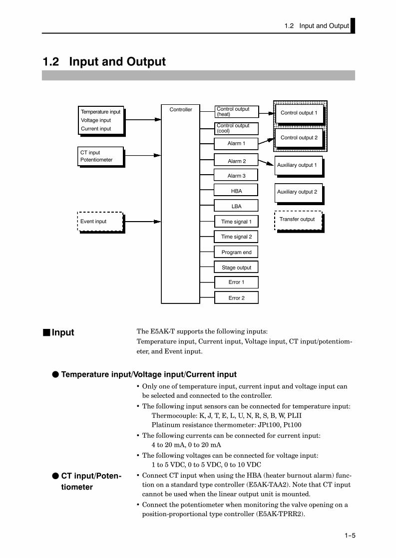
The E5AK-T supports the following inputs:Temperature input, Current input, Voltage input, CT input/potentiom-eter, and Event input.
F Temperature input/Voltage input/Current input• Only one of temperature input, current input and voltage input canbe selected and connected to the controller.
• The following input sensors can be connected for temperature input:Thermocouple: K, J, T, E, L, U, N, R, S, B, W, PLIIPlatinum resistance thermometer: JPt100, Pt100
• The following currents can be connected for current input:4 to 20 mA, 0 to 20 mA
• The following voltages can be connected for voltage input:1 to 5 VDC, 0 to 5 VDC, 0 to 10 VDC
• Connect CT input when using the HBA (heater burnout alarm) func-tion on a standard type controller (E5AK-TAA2). Note that CT inputcannot be used when the linear output unit is mounted.
• Connect the potentiometer when monitoring the valve opening on aposition-proportional type controller (E5AK-TPRR2).
J Input
F CT input/Poten-tiometer

CHAPTER 1 INTRODUCTION
E5AK
1--6
Add on the input unit (E53-CKB) when using event input. You can se-lect from the following six event inputs:
Run/Reset, Remote/Local, Auto/Manual, Hold/Hold Cancel, Advance,Pattern
The output functions of the E5AK-T do not operate for five seconds after theE5AK-T is turned ON.
The E5AK-T supports the following five outputs:Control output 1Control output 2Auxiliary output 1Auxiliary output 2Transfer output
When using control output 1 and 2, set the output unit (sold sepa-rately). Nine output units are available to suit the output circuit config-uration.When using transfer output, add on the communication unit(E53-AKF).
• The E5AK-T supports the following thirteen output functions:Control output (heat), Control output (cool), Alarms 1 to 3, HBA,LBA, Time Signals 1 and 2, Program End, Stage Output,Error 1 (input error), Error 2 (A/D converter error)
• Assign these output functions to control output 1, control output 2,auxiliary output 1, and auxiliary output 2.However, note that as control output 1 is used as the open output andcontrol output 2 is used as close output on a position-proportionaltype controller (E5AK-TPRR2), control outputs 1 and 2 cannot beused as assignment destinations. Also, of the output functions, controloutput (heat), control output (cool), HBA and LBA are disabled.
• On a standard type controller, there are restrictions on how assign-ment destinations (control output 1, control output 2, auxiliary out-put 1, and auxiliary output 2) can be used. For details, see Chapter 3Basic Operation/3.3 Setting Output Specifications (page 3-7).
• In the example on the previous page, “control output (heat)” is as-signed to “control output 1”, “alarm 1” is assigned to “control output2”, and “alarm 2” is assigned to “auxiliary output 1”. Accordingly, theconfiguration is such that heating control output is connected to con-trol output 1, and alarm output is connected to control output 2 andauxiliary output 1.
• Control outputs 1 and 2 are used depending on the differences in con-trol method as follows:
F Event input
JOutput
F Output assign-ments

1.2 Input and Output
E5AK
1--7
Control Method Model Control Output 1/Control Output 2
Standard control E5AK-TAA2 AC100-240E5AK-TAA2 AC/DC24
Control output (heat)/ Alarm, etc.
Heating andcooling control
E5AK-TAA2 AC100-240E5AK-TAA2 AC/DC24
Control output (heat)/ Control output (cool)
Position-propor-tional control
E5AK-TPRR2AC100-240E5AK-TPRR2 AC/DC24
Open/Close
• The E5AK-T supports the following five transfer outputs:
Set point, Process value, Heating side manipulated variable,Cooling side manipulated variable, Valve opening
However, note that heating/cooling side manipulated variables can beoutput only on standard type controllers, and valve opening can be out-put only on position-proportional type controllers.
• These transfer outputs can be output after being scaled. Setting of anupper limit value smaller than the lower limit value is allowed, so re-verse scaling can also be carried out.
F Transfer output

CHAPTER 1 INTRODUCTION
E5AK
1--8
1.3 Program
E5AK-T allows you to configure programs made up of a maximum ofeight patterns (pattern 0 to 7).The number of steps (16 maximum) in each pattern can be specified inparameters.
Pattern 7
Pattern 1
Pattern 0
Step 0 Step 1 Step 2 Step 15
• Generally, the “time setup method” is used to configure programs. Bythis method, set points at each step and time are used as program ele-ments. However, the “ramp rise rate setup method” can also be used.By this method, the set point, ramp time and soak times are used asprogram elements.
• Generally, the target patterns are specified before the program isexecuted.
• In parameter setup, you can specify repeated execution of the samepattern (Repeat) or consecutive execution of all patterns 0 to 7 (Runall).
• During program operation, steps can be skipped (Advance) and thecontrol monitoring can be paused (Hold).
• When the wait width is specified in parameter setup, the programdoes not go to the next step and waits until the PV reaches the speci-fied time (wait width) at the end of each step.
• Alarms that are assigned as outputs operate referenced to the alarmvalues preset to each pattern.
• Time signals, program end and stage output can be output accordingto output assignment.
• ON/OFF signals are output as time signals according to the timerthat takes a specified step as its start point.
JHow programsare structured
JProgram opera-tion
F Step operation
FWait operation
JAlarm output
JProgram output

1.4 Parameters and Menus
E5AK
1--9
1.4 Parameters and Menus
E5AK-T parameters are distributed between the following ten modes:Protect modeManual modeLevel 0 modeProgram modeLevel 1 modeLevel 2 modeSetup modeExpansion modeOption modeCalibration mode
The settings of parameters in each of eight modes (excluding the protectmode and manual mode) can be checked and modified by selection onthe menu display.
The protect function is for preventing unwanted modification of param-eters, and switching between run and reset operation or auto andmanual operation.
In this mode, the controller can be switched to manual operation. Themanipulated variable can be manipulated manually only in this mode.
Set the controller to this mode during normal operation. In this mode,you can change the set point and pattern during operation, and executestep operation (e.g. advance). You can only monitor (not change) theprocess value, step No., standby time, pattern elapsing time, patternexecution count and manipulated variable.
This is the programming mode. In this mode, you can set the number ofsteps used in each pattern, pattern execution count, alarm values, setpoints for each step, step time, and time signals for two steps.
This is the main mode for adjusting control. In this mode, you canexecute AT (auto-tuning), and set up the control period, PID parame-ters and heater burnout alarm (HBA) conditions.
This is the auxiliary mode for adjusting control. In this mode, you canset the parameters for limiting the manipulated variable, switch be-tween the remote and local modes, and set the loop break alarm (LBA),alarm hysteresis and the digital filter value of inputs.
This is the mode for setting the basic specifications. In this mode, youcan set parameters that must be checked or set before operation such asthe input type, scaling, output assignments and direct/reverse opera-tion.
JParameter types
F Protect mode
F Manual mode
F Level 0 mode
F Program mode
F Level 1 mode
F Level 2 mode
F Setup mode

CHAPTER 1 INTRODUCTION
E5AK
1--10
This is the mode for setting expanded functions. In this mode, you canset SP setting limitter, switching between advanced PID control or ON/OFF control, program time unit, selection of step time/rate of rise pro-gramming, time unit of ramp rise rate, and the time for automatic re-turn to the monitoring display.
This is the mode for setting optional functions. You can select this modeonly when an option unit is mounted in the controller. In this mode,you can set the communications conditions, transfer output and eventinput parameters to match the type of option unit mount in the control-ler. Heater burnout alarm function and position-proportional traveltime are also located in this mode.
This mode is provided so that the user can calibrate inputs and output.When calibrating input, the selected input type is calibrated. Whereas,transfer output can be calibrated only when the communication unit(E53-AKF) is set in the controller.
The following diagram shows the order in which modes are selected.
1 second min.
1 second min.
1 second min.
1 second min.
1 second min.
1 second min.
1 second min.
1 second min.
Level 0 mode
Program mode
Level 2 mode
Setup mode
Expansion mode
Option mode
Calibration mode
Power ON
Level 1 mode
Manual mode
Protect mode
1 second min.
1 second min.
1 second min.
1 second min.
1 second min.
+
+
+
+
+
RUN/RST
RUN/RST
RUN/RST
• To select the menu display in any of the above modes (excluding theprotect mode and manual mode), press the key for 1 second mini-mum. When you have selected the menu display, the previous mode isselected. For example, if you selected the menu display while in thelevel 0 mode, the No.2 display changes to [ ] as shown on the left.
• To move to the desired mode after you have entered the menu display,select the desired mode using the keys and hold down the
key for one second minimum. The display switches to the firstparameter of the mode that you specified.
F Expansion mode
F Option mode
F Calibration mode
JSelecting modes
1.4 Parameters and Menus
E5AK
1--11
• Protected modes cannot be selected. Also, the menu display does notappear when modes are protected up to the program mode.
• If you select [ ], [ ], [ ] or [ ] in the menu display,the level 0, program, level 1 and level 2 modes, respectively, are se-lected.These modes are selected with control still continuing.
• If you select[ ] [ ] [ ] or [ ] in the menu display, thesetup, expansion, option and calibration modes, respectively, are se-lected.When these modes are selected, the control is reset. So, control out-puts and auxiliary output are turned OFF. When another mode is se-lected while in these modes control, reset is canceled.
• To set the controller to the protect mode or to return to the level 0
mode from the protect mode, press the RUN/RST key and the key
simultaneously for 1 second minimum.
• To set the controller to the manual mode, press the key for onesecond minimum with the key held down in the level 0 to 2modes. To return to the level 0 mode in the manual mode, press the
key for one second minimum with the key pressed. Be sureto press the key first in this operation.
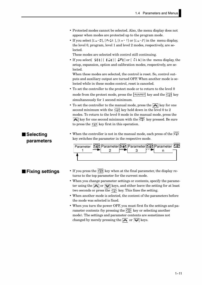
• When the controller is not in the manual mode, each press of thekey switches the parameter in the respective mode.
Parameter1
Parameter2
Parameter3
Parametern
• If you press the key when at the final parameter, the display re-turns to the top parameter for the current mode.
• When you change parameter settings or contents, specify the parame-ter using the or keys, and either leave the setting for at leasttwo seconds or press the key. This fixes the setting.
• When another mode is selected, the content of the parameters beforethe mode was selected is fixed.
• When you turn the power OFF, you must first fix the settings and pa-rameter contents (by pressing the key or selecting anothermode). The settings and parameter contents are sometimes notchanged by merely pressing the or keys.
JSelectingparameters
JFixing settings

CHAPTER 1 INTRODUCTION
E5AK
1--12
1.5 About the Communications Function
The E5AK-T can be provided with a communications function that al-lows you to check and set controller parameters from a host computer.If the communications function is required, add on the communicationsunit.For details on the communications function, refer to Chapter 6.
When using the communications function on the RS-232C interface,add on the communications unit (E53-AK01).
When using the communications function on the RS-422 interface, addon the communications unit (E53-AK02).
When using the communications function on the RS-485 interface, addon the communications unit (E53-AK03).
F RS-232C
F RS-422
F RS-485

1.6 About Calibration
E5AK
1--13
1.6 About Calibration
The E5AK-T controller is calibrated before shipment from the factory.So, the user need not calibrate the E5AK-T controller during regularuse.
However, if the E5AK-T controller must be calibrated by the user, usethe parameters provided for the user to calibrate temperature input,analog input (voltage, current) and transfer output. In this case, notethat the results of calibration will not be assured.Also, note that calibration data is updated to the latest value each timethat the E5AK-T controller is calibrated. Calibration data set beforeshipment from the factory cannot be returned to after calibration bythe user.
The input type selected in parameters is the item to be calibrated. TheE5AK-T is provided with the following four calibration parameters:
• Thermocouple
• Platinum resistance thermometer
• Current input
• Voltage input
Two parameters are provided for thermocouple and voltage input.
Transfer output also can be calibrated when the communications unit(E53-AKF) is added on.
When calibrating each item, the calibration data is temporarily regis-tered. This data can be registered as final calibration data only when allitems have been newly calibrated. So, all items must be temporarilyregistered when the E5AK-T controller is calibrated.When registering data, information regarding whether or not calibra-tion has been carried out is also registered.
To calibrate these items, the user must prepare separate measuring de-vices and equipment. For details on handling these measuring devicesand equipment, refer to the respective manuals.
For details, see Chapter 7 Calibration.
F Calibratinginputs
F Calibrating trans-fer output
F Registering cal-ibration data

CHAPTER 1 INTRODUCTION
E5AK
1--14

CHAPTER 2 PREPARATIONS
E5AK
2--1
CHAPTER 2PREPARATIONS
This chapter describes the operations (e.g. setup, installation andwiring) you should carry out before turning the E5AK-T ON.
CHAPTER2
2.1 Setup 2-2. . . . . . . . . . . . . . . . . . . . . . . . . . . . . . . . .
Draw-out 2-2. . . . . . . . . . . . . . . . . . . . . . . . . . . . . .
Setting up the output unit 2-3. . . . . . . . . . . . . .
Setting up the option unit 2-4. . . . . . . . . . . . . . .
2.2 Installation 2-5. . . . . . . . . . . . . . . . . . . . . . . . . . . .
Dimensions 2-5. . . . . . . . . . . . . . . . . . . . . . . . . . . .
Panel cutout 2-5. . . . . . . . . . . . . . . . . . . . . . . . . . .
Mounting 2-6. . . . . . . . . . . . . . . . . . . . . . . . . . . . .
2.3 Wiring Terminals 2-8. . . . . . . . . . . . . . . . . . . . . .
Terminal arrangement 2-8. . . . . . . . . . . . . . . . .
Precautions when wiring 2-8. . . . . . . . . . . . . . .
Wiring 2-8. . . . . . . . . . . . . . . . . . . . . . . . . . . . . . . .

CHAPTER 2 PREPARATIONS
E5AK
2--2
2.1 Setup
• On a standard type controller, set up the output units for control out-puts 1 and 2 before mounting the controller.
• On a position-proportional type controller, the relay output unit isalready mounted. So, this setup operation is unnecessary. (That is, donot replace the currently mounted unit with other output units.)
• When setting up the output units, draw out the internal mechanismfrom the housing, and insert the output units into the sockets for con-trol outputs 1 and 2.
When drawing out the internal mechanism from the housing, prepare aPhillips screwdriver matched to the size of the screw on the lower partof the front panel.
(1) Press down on the hook on the top of the front panel, and turn thePhillips screwdriver to the left to loosen the screw on the lowerpart of the front panel.
(2) Draw out the internal mechanism towards you holding both sidesof the front panel.
Tighten this screw by a torque of 0.3 to 0.5 N⋅m (approx. 3 to 5 kgf⋅cm).Fixing Screw forFront Panel
JDraw-out

2.1 Setup
E5AK
2--3
JSetting up the output unit
• Check the type of the output unit you are about to set up.
• For details on types of output unit and main specifications, see page2-7.
(1) Check the positions of the sockets you are about to insert the out-put units into as shown in the following diagram.
OUT2
OUT1
Bracket
(2) Insert the output unit for control output 1 into the socket “OUT1”and the output unit for control output 2 into the socket “OUT2”.
(3) Fasten the output units with the bracket (accessory).
F Before setup
F Procedure

CHAPTER 2 PREPARATIONS
E5AK
2--4
JSetting up the option unit
• Check the type of the option unit you are about to set up.
• For details on types of option unit and main specifications, see Appen-dix, Model List (page A-12) and Appendix, Option Unit Ratings andCharacteristics (page A-4).
• For details on the relationship between units and terminals, see page2-8.
(1) Remove the power board and option boards in the order shown inthe following diagram.
1
2
(2) Insert the option units into the sockets for options 1 to 3. The fol-lowing diagram shows the relationship between option units andmounting positions.
Option 1E53--AKB: Event inputs 1/2E53--AK01: RS--232CE53--AK02: RS--422E53--AK03: RS--485Option 2
E53--AKF: Transfer output
Option 3E53--AKB: Event inputs 3/4
(3) Mount the option boards and the power board in the order shown.
F Before setup
F Procedure

2.2 Installation
E5AK
2--5
2.2 Installation
JDimensions96j 13.5 100
91
j
112
JPanel cutout
• Recommended panel thickness is 1 to 8mm.
• Maintain the specified vertical and hori-zontal mounting space between eachcontroller.Controllers must not be closely mountedvertically or horizontally.
92 +0.80
92 +0.80
Unit (mm)110 min.
120 min.

CHAPTER 2 PREPARATIONS
E5AK
2--6
(1) Insert the E5AK-T controller into the mounting hole in the panel.
(2) Fit the mounting bracket (accessory) into the fixing slots on the topand bottom of the rear case.
(3) Tighten the mounting bracket screws alternately a little at a timeuntil the ratchet starts to slide.
JMounting

2.2 Installation
E5AK
2--7
F Setting up the terminal covers• Fasten the terminal covers (E53-COV0809) to protect terminals.
• E5AK-VV2-500 controller is provided with terminal covers.
• Use E53-COV09 for terminals 1 to 10, and E53-COV08 for terminals11 to 33.
• Fasten the terminal covers as follows by using the snap pins.
E5AK-T
E53-COV0809
• To remove the terminal covers, pull the edges of the snap pins.

CHAPTER 2 PREPARATIONS
E5AK
2--8
2.3 Wiring Terminals
JTerminal arrangement
10
OUT1
OUT2
SUB1
SUB2
9
8
7
6
5
4
3
2
1
30
29
28
27
26
25
24
23
2221
20
19
18
17
16
15
14
13
12
11
31 32
33
TRSF
EV3/4
EV1/2RS232CRS422RS485
CTPTMR
TCPtIV
TRSF : Transfer outputEV1 to 4 : Event inputsPTMR : PotentiometerSOURCE : 100 to 240 VAC, 50/60 Hz 16VA or 24VAC/DC, 50/60 Hz, 12VA 8W
SOURCE
• On some models, terminals are not used and are left free. Do not wirethese terminals.
• Separate input leads and power lines in order to protect the controllerand its lines from external noise.
• We recommend using solderless terminals when wiring the controller.
• Tighten the terminal screws using a torque no greater than 0.78 N¡m(8kgf¡cm).
• Use the following type of solderless terminals for M3.5 screws.
7.2mm max.
7.2mm max.
In the following wiring diagrams, the left side of the terminal Nos. indi-cates the inside of the controller.
• Input power to terminals Nos. 9 and 10. Power specifications are as fol-lows:100 to 240 VAC, 50/60 Hz, approx. 16 VAor24 VAC, 50/60 Hz, approx. 12 VA24 VDC, 8W
JPrecautionswhen wiring
JWiring
F Power supply
10987654321
30292827262524232221
20191817161514131211
31 32
33
2.3 Wiring Terminals
E5AK
2--9
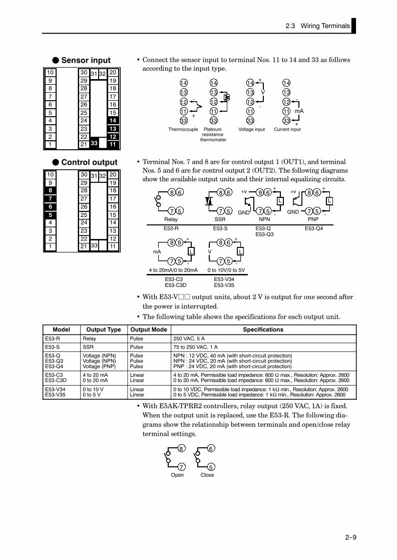
• Connect the sensor input to terminal Nos. 11 to 14 and 33 as followsaccording to the input type.
14
13
12
11
33
14
13
12
11
33
14
13
12
11
33
14
13
12
11
33
-
+
-
+
-
+
mA
Thermocouple Platinumresistancethermometer
Voltage input Current input
V
• Terminal Nos. 7 and 8 are for control output 1 (OUT1), and terminalNos. 5 and 6 are for control output 2 (OUT2). The following diagramsshow the available output units and their internal equalizing circuits.
8 6
7 5
8 6
7 5
8 6
7 5
8 6
7 5
8 6
7 5
8 6
7 5
L
E53-R E53-S E53-Q4
E53-V34E53-V35
SSR PNP
0 to 10V/0 to 5V
+v+
- GNDRelay
L
+
-
E53-QE53-Q3
NPN
E53-C3E53-C3D
4 to 20mA/0 to 20mA
L LmA V
+
-
+
-
GND
+v
• With E53-Vjj output units, about 2 V is output for one second afterthe power is interrupted.
• The following table shows the specifications for each output unit.
Model Output Type Output Mode SpecificationsE53-R Relay Pulse 250 VAC, 5 A
E53-S SSR Pulse 75 to 250 VAC, 1 A
E53-QE53-Q3E53-Q4
Voltage (NPN)Voltage (NPN)Voltage (PNP)
PulsePulsePulse
NPN : 12 VDC, 40 mA (with short-circuit protection)NPN : 24 VDC, 20 mA (with short-circuit protection)PNP : 24 VDC, 20 mA (with short-circuit protection)
E53-C3E53-C3D
4 to 20 mA0 to 20 mA
LinearLinear
4 to 20 mA, Permissible load impedance: 600 Ω max., Resolution: Approx. 26000 to 20 mA, Permissible load impedance: 600 Ω max., Resolution: Approx. 2600
E53-V34E53-V35
0 to 10 V0 to 5 V
LinearLinear
0 to 10 VDC, Permissible load impedance: 1 kΩ min., Resolution: Approx. 26000 to 5 VDC, Permissible load impedance: 1 kΩ min., Resolution: Approx. 2600
• With E5AK-TPRR2 controllers, relay output (250 VAC, 1A) is fixed.When the output unit is replaced, use the E53-R. The following dia-grams show the relationship between terminals and open/close relayterminal settings.
8
7Open
6
5Close
F Sensor input10987654321
30292827262524232221
20191817161514131211
31 32
33
F Control output10987654321
30292827262524232221
20191817161514131211
31 32
33

CHAPTER 2 PREPARATIONS
E5AK
2--10
• Terminal Nos.3 and 4 are for auxiliary output 1 (SUB1) and terminalNos.1 and 2 are for auxiliary output 2 (SUB2).
• The internal equalizing circuits for the auxiliary outputs are as fol-lows:
4
3
2
1
Auxiliaryoutput 1
Auxiliaryoutput 2
• Output specifications are as follows:SPST-NO, 250 VAC, 3 A
• When the HBA function on an E5AK-TAA2 controller is used, connectCT input (CT) to terminal Nos.15 and 17. When monitoring the valveopening on an E5AK-TPRR2 controller, connect the potentiometer(PTMR) to terminal Nos.15 to 17. Connect each of these inputs as fol-lows:
17
16
15
17
16
15C
W
O
CT
CT input Potentiometer
• For details on CT inputs, see Appendix, About Current Transformer(CT) Input (page A-5).
• For details on the potentiometer, see the Instruction Manual for thevalve connected to the controller.The meaning of terminal symbols is as follows:O: OPEN, W: WIPE, C: CLOSE
The variable resistance range is 100 Ω to 2.5 kΩ.
The E5AK-T has independent power suppliesfor each of the terminal blocks shown on theright.
About Isolation
10987654321
30292827262524232221
20191817161514131211
31 32
33
A B C
B
F D
C
E
F Auxiliary output10987654321
30292827262524232221
20191817161514131211
31 32
33
F CT input/Potentiometer
10987654321
30292827262524232221
20191817161514131211
31 32
33
2.3 Wiring Terminals
E5AK
2--11
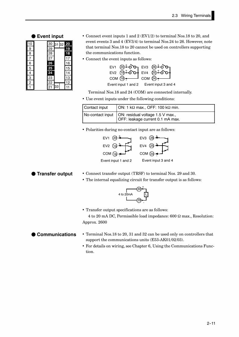
• Connect event inputs 1 and 2 (EV1/2) to terminal Nos.18 to 20, andevent events 3 and 4 (EV3/4) to terminal Nos.24 to 26. However, notethat terminal Nos.18 to 20 cannot be used on controllers supportingthe communications function.
• Connect the event inputs as follows:
20
19
18
26
25
24
+
+
-Event input 1 and 2 Event input 3 and 4
EV1
EV2
COM
EV3
EV4
COM
+
+
-
Terminal Nos.18 and 24 (COM) are connected internally.
• Use event inputs under the following conditions:
Contact input ON: 1 kΩ max., OFF: 100 kΩ min.
No-contact input ON: residual voltage 1.5 V max.,OFF: leakage current 0.1 mA max.
• Polarities during no-contact input are as follows:
20
19
18
26
25
24
+
+
-Event input 1 and 2 Event input 3 and 4
EV1
EV2
COM
EV3
EV4
COM
+
+
-
• Connect transfer output (TRSF) to terminal Nos. 29 and 30.
• The internal equalizing circuit for transfer output is as follows:
30
29
4 to 20mA L
+
-
• Transfer output specifications are as follows:
4 to 20 mA DC, Permissible load impedance: 600 Ωmax., Resolution:Approx. 2600
• Terminal Nos.18 to 20, 31 and 32 can be used only on controllers thatsupport the communications units (E53-AK01/02/03).
• For details on wiring, see Chapter 6, Using the Communications Func-tion.
F Event input10987654321
30292827262524232221
20191817161514131211
31 32
33
F Transfer output
F Communications

CHAPTER 2 PREPARATIONS
E5AK
2--12

CHAPTER 3 BASIC OPERATION
E5AK
3--1
CHAPTER 3BASIC OPERATION
This chapter describes actual examples for understanding the basicoperation of the E5AK-T.
CHAPTER3
3.1 Convention Used in this Chapter 3-2. . . . . . . .
3.2 Setting Input Specifications 3-4. . . . . . . . . . . . .
Input type 3-4. . . . . . . . . . . . . . . . . . . . . . . . . . . . .
Temperature input 3-5. . . . . . . . . . . . . . . . . . . . .
Analog input 3-5. . . . . . . . . . . . . . . . . . . . . . . . . .
3.3 Setting Output Specifications 3-7. . . . . . . . . . .
Output assignments 3-7. . . . . . . . . . . . . . . . . . . .
Direct/reverse operation 3-8. . . . . . . . . . . . . . . .Control period 3-8. . . . . . . . . . . . . . . . . . . . . . . . .
3.4 Setting Alarm Type 3-10. . . . . . . . . . . . . . . . . . . .
Alarm type 3-10. . . . . . . . . . . . . . . . . . . . . . . . . . . .
Alarm value 3-10. . . . . . . . . . . . . . . . . . . . . . . . . . .
Alarm hysteresis 3-11. . . . . . . . . . . . . . . . . . . . . . .
Close in alarm/open in alarm 3-11. . . . . . . . . . . .
3.5 Setting Patterns 3-14. . . . . . . . . . . . . . . . . . . . . . .
Pattern No. 3-15. . . . . . . . . . . . . . . . . . . . . . . . . . . .
Number of steps 3-15. . . . . . . . . . . . . . . . . . . . . . .
Step SP/Step time 3-15. . . . . . . . . . . . . . . . . . . . . .
Alarm value 3-16. . . . . . . . . . . . . . . . . . . . . . . . . . .
3.6 Protect Mode 3-19. . . . . . . . . . . . . . . . . . . . . . . . . .
Security 3-19. . . . . . . . . . . . . . . . . . . . . . . . . . . . . . .
Key protect 3-19. . . . . . . . . . . . . . . . . . . . . . . . . . . .
3.7 Starting and Stopping Operation 3-21. . . . . . . .
3.8 Adjusting Control Operation 3-22. . . . . . . . . . . .
Changing currently running programs 3-22. . .
Manual operation 3-24. . . . . . . . . . . . . . . . . . . . . .Auto-tuning (A.T.) 3-25. . . . . . . . . . . . . . . . . . . . .

CHAPTER 3 BASIC OPERATION
E5AK
3--2
3.1 Convention Used in this Chapter
This chapter describes basic E5AK-T operations such as how to set upparameters, start and stop operation, and adjust control operation.
For more complex control examples, refer to Chapter 4 Applied Opera-tion and Chapter 5 Parameters.
The following diagram shows the basic flow of operation.
Power ON
Setup
Setting input specifications
Setting output specifications
Setting alarm output
Protecting parameters
Operation
Start
Adjustment
Stop
Power OFF
Setting patterns
The descriptions in this chapter follow the order of basic operationsshown in the flow above. Examples of operation of each of the items aredescribed up to completion of parameter setup. However, you mustmove to the top parameter of the following setting. For example, whenyou have finished “setting input specifications” and you want to “setoutput specifications,” move to the top parameter of “setting outputspecifications” from the bottom parameter of “setting input specifica-tions.”For details on moving to parameters between items, refer Chapter, Se-lecting modes and Selecting parameters (page 1-10).
F Basic OperationFlow
3.1 Convention Used in this Chapter
E5AK
3--3
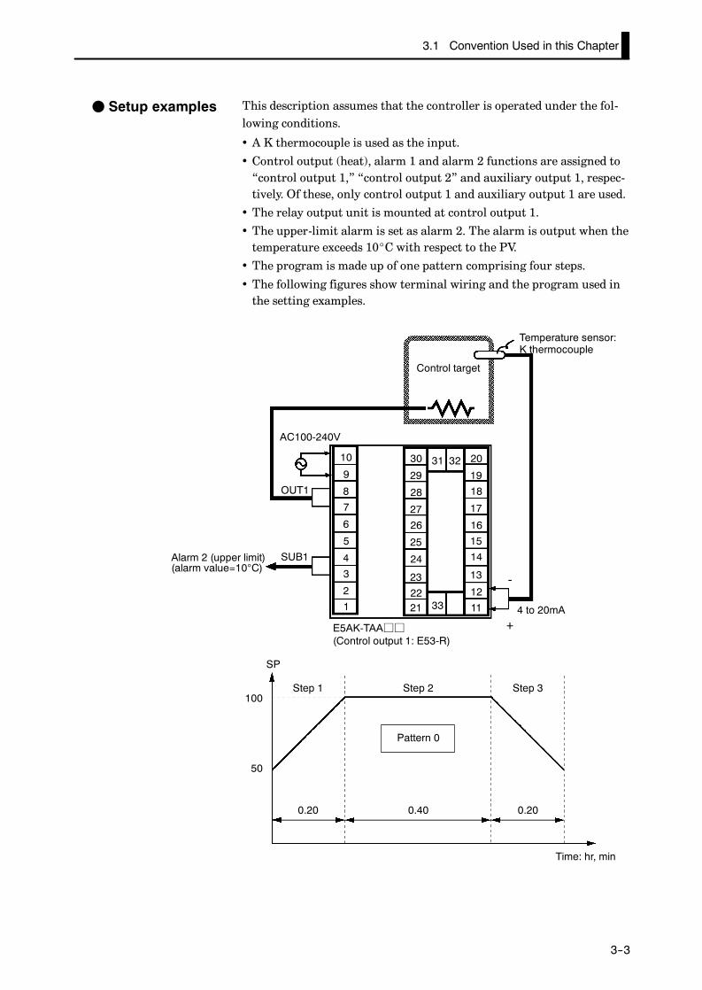
This description assumes that the controller is operated under the fol-lowing conditions.
• A K thermocouple is used as the input.
• Control output (heat), alarm 1 and alarm 2 functions are assigned to“control output 1,” “control output 2” and auxiliary output 1, respec-tively. Of these, only control output 1 and auxiliary output 1 are used.
• The relay output unit is mounted at control output 1.
• The upper-limit alarm is set as alarm 2. The alarm is output when thetemperature exceeds 10_C with respect to the PV.
• The program is made up of one pattern comprising four steps.
• The following figures show terminal wiring and the program used inthe setting examples.
OUT1
4 to 20mA
Temperature sensor:K thermocouple
Alarm 2 (upper limit)(alarm value=10°C)
Control target
SUB1
-
+E5AK-TAAjj(Control output 1: E53-R)
10
9
8
7
6
5
4
3
2
1
30
29
28
27
26
25
24
23
2221
20
19
18
17
16
15
14
13
12
11
31 32
33
AC100-240V
Step 1 Step 2 Step 3
Pattern 0
Time: hr, min
0.20 0.40 0.20
50
100
SP
F Setup examples

CHAPTER 3 BASIC OPERATION
E5AK
3--4
3.2 Setting Input Specifications
Setting input specifications
Input type
Temperature input?
Temperature unit
Temperature input shift
End of setup
Decimal point
Scaling
Setup mode
Level 2 mode
N
Y
• With temperature input, scaling and decimal point parameters neednot be set as this information is determined by the input (sensor)type. (These parameters are not displayed.) Note that temperatureunit and temperature input shift parameters need to be set.
• With analog input, the “scaling upper limit”, “scaling lower limit”and “decimal point” parameters need to be set.
• Set the type No. (0 to 21) in the “input type” parameter (Set upmode). The factory setting is “2: K1 (thermocouple).”
• For details on input types and setting ranges, see page 5-31.
J Input type

3.2 Setting Input Specifications
E5AK
3--5
JTemperature input• To switch the temperature unit from “_C” to“_F” when input is tem-perature, switch the “_C/_F selection” parameter (setup mode) from“ ” to “ ”.
• When input is temperature input, the upper and lower limit values ofthe sensor can be shifted linearly. For example, if both the upper andlower limit values are shifted by 1.2_C, the process value (before shift)is regarded as 201.2_C after shift when input is 200_C before shift.
• To set input shift, set shift values in the “input shift upper limit” and“input shift lower limit” parameters (level 2 mode).
0100
Temperature
Upper limit value
Lower limit value
Input shift upper limit value
After shift
Before shift
Input shift lowerlimit value
Input (%FS)
• When the analog input (the voltage input and current input) is se-lected, scaling matched to the control is required.
• The “scaling upper limit”, “scaling lower limit” and “decimal point”parameters (setup mode) are used for scaling. These parameters can-not be used when the temperature input type is selected.
• The “scaling upper limit” parameter sets the physical quantity to beexpressed by the upper limit value of input, and the “scaling lowerlimit” parameter sets the physical quantity to be expressed by thelower limit value of input. The “decimal point” parameter sets thenumber of digits past the decimal point.
• The following figure shows a scaling example of 4 to 20 mA input. Af-ter scaling, the humidity can be directly read. In this case, the “deci-mal point” parameter is set to “1”.
100%FS0
Readout (humidity)
Scaling upper limitvalue (95.0%)
Scaling lower limitvalue (10.0%)
Input (4 to 20 mA)
F Temperature unit
F Temperatureinput shift
JAnalog input
CHAPTER 3 BASIC OPERATION
E5AK
3--6
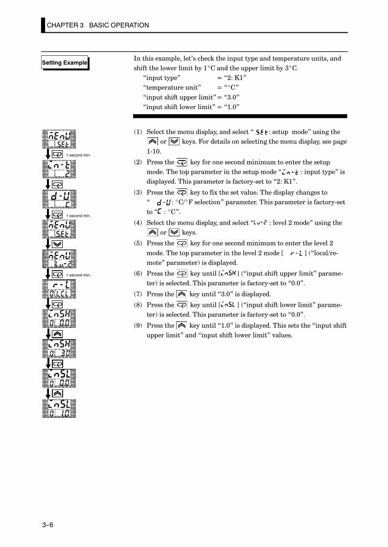
In this example, let’s check the input type and temperature units, andshift the lower limit by 1_C and the upper limit by 3_C.“input type” = “2: K1”“temperature unit” = “_C”“input shift upper limit”= “3.0”“input shift lower limit” = “1.0”
(1) Select the menu display, and select “ : setup mode” using theor keys. For details on selecting the menu display, see page
1-10.
(2) Press the key for one second minimum to enter the setupmode. The top parameter in the setup mode “ : input type” isdisplayed. This parameter is factory-set to “2: K1”.
(3) Press the key to fix the set value. The display changes to“ : _C/_F selection” parameter. This parameter is factory-setto “ : _C”.
(4) Select the menu display, and select “ : level 2 mode” using theor keys.
(5) Press the key for one second minimum to enter the level 2mode. The top parameter in the level 2 mode [ ] (“local/re-mote” parameter) is displayed.
(6) Press the key until [ ] (“input shift upper limit” parame-ter) is selected. This parameter is factory-set to “0.0”.
(7) Press the key until “3.0” is displayed.
(8) Press the key until [ ] (“input shift lower limit” parame-ter) is selected. This parameter is factory-set to “0.0”.
(9) Press the key until “1.0” is displayed. This sets the “input shiftupper limit” and “input shift lower limit” values.
Setting Example
1 second min.
1 second min.
1 second min.

3.3 Setting Output Specifications
E5AK
3--7
3.3 Setting Output Specifications
Some output specifications are different according to controller type,standard or position-proportional. The following table summarizeswhich output-related parameter settings are supported.
Parameter StandardType
Position-proportional
TypeControl output 1 assignment F
Control output 2 assignment F
Auxiliary output 1 assignment F F
Auxiliary output 2 assignment F F
Direct/reverse operation F F
Control period (heat) F
Control period (cool) F
(F Indicates that an output specification is supported.)
JOutput assignmentsOutput assignments are described according to controller type.
• Thirteen outputs are supported. These functions are assigned to con-trol outputs 1 and 2, and auxiliary outputs 1 and 2.
• Restrictions on assignment destination are placed on some of the out-puts.
• The following table shows where outputs may be assigned to.
AssignmentDestination
Control Output Auxiliary OutputDestination
Output Function 1 2 1 2
Control output (heat) F F
Control output (cool) F F
Alarm 1 F F F F
Alarm 2 F F F F
Alarm 3 F F F F
HBA F F F F
LBA F F F F
Time signal 1 F F F F
Time signal 2 F F F F
Program end F F F F
Stage output F F F F
Error 1 : Input error F F
Error 2 : A/D convertor error F F
With control output (cool), the conditions for switching from standard controlto heating and cooling control are reached when the output function is assignedat the cooling side during heating and cooling control.
In other words, heating and cooling control is carried out when con-trol output (cool) is assigned, and standard control is carried outwhen output is not assigned. For details on heating and cooling con-trol, see Chapter 4 Applied Operation/4.1 Selecting the Control Meth-od (page 4-2).
F Standard type

CHAPTER 3 BASIC OPERATION
E5AK
3--8
• Factory settings are as follows:control output 1 = Control output (heat)control output 2 = Alarm 1auxiliary output 1 = Alarm 2auxiliary output 2 = Alarm 3
• Output assignments are set in the “control output 1 assignment”,“control output 2 assignment”, “ auxiliary output 1 assignment” and“ auxiliary output 2 assignment” parameters (setup mode).
• Position-proportional type controllers support nine output functions.These are assigned to auxiliary outputs 1 and 2.
• Restrictions on assignment destinations are placed on some of theoutputs. The following table shows where outputs may be assigned to.
AssignmentDestination
Control Output Auxiliary OutputDestination
Output Function 1 2 1 2
Alarm 1 F F
Alarm 2 F F
Alarm 3 F F
Time signal 1 F F
Time signal 2 F F
Stage output F F
Program end output F F
Error 1 : Input error F F
Error 2 : A/D converter error F F
• “Direct operation” (or normal operation) refers to control where the ma-nipulated variable is increased according to the increase in the processvalue. Alternatively, “reverse operation” refers to control where the ma-nipulated variable is decreased according to the decrease in the processvalue.For example, when the process value (PV) (temperature), is lowerthan the set point (SP) (temperature), in a heating control system, themanipulated variable increases by the difference between the PV andSP values.Accordingly, this becomes “reverse operation” in a heating controlsystem, or alternatively, “direct operation” in a cooling control sys-tem.
• Direct/reverse operation is set in the “direct/reverse operation” pa-rameter (setup mode). Default is “ : reverse operation”.
• On position-proportional type controllers, this item cannot be set.• On a standard type controller, when the output unit is for pulse out-put such as relay output, set the pulse output cycle (control period).Though a shorter control period provides better control performance,the control period should be set to 20 seconds minimum taking thelife expectancy of the output unit into consideration when the outputunit is for relay output.
• The control period is set in the “control period (heat)” parameter(level 1 mode). Default of the “control period” parameter is factory-set to “20:20 seconds.” The “control period (cool)” output function isnot assigned. So, the “control period (cool)” parameter cannot be set.
F Position-propor-tional type
JDirect/reverseoperation
JControl period

3.3 Setting Output Specifications
E5AK
3--9
All of the above settings in this example are factory settings. In this ex-ample, let’s check the parameter settings.In this example, the parameters are set as follows:“control output 1 assignment” = “control output (heat)”“auxiliary output 1 assignment” = “alarm output 2”“direct/reverse operation” = “reverse operation”“control period” = “20 secs”
(1) Select the menu display, and select “ : setup mode” using theor keys. For details on selecting the menu display, see page
1-10.
(2) Press the key for one second minimum to enter the setupmode. The top parameter in the setup mode “ : input type” isdisplayed.
(3) Press the key until [ ] (“control output 1 assignment”parameter) is displayed. Default is [ ].
(4) As the setting in this example is to be left as it is, press the keytwice. The display changes to [ ] (“auxiliary output 1 assign-ment” parameter). Default is [ ].
(5) As the setting in this example is to be left as it is, press the keyuntil [ ] (“direct/reverse operation” parameter) is displayed.Default is [ ].
(6) As the setting in this example is to be left as it is, press the orkeys to select “ : level 1 mode”. For details on selecting
the menu display, see page 1-7.
(7) Press the key for one second minimum to enter the level 1mode. The top parameter in the level 1 mode “ : Proportionalband” is displayed.
(8) Press the key until [ ] (“control period (heat)” parameter)is displayed. Default is “20”. As the setting in this example is to beleft as its is, quit key operation.
Setting Example
1 second min.
1 second min.
1 second min.
CHAPTER 3 BASIC OPERATION
E5AK
3--10
3.4 Setting Alarm Type
• Three alarm outputs are supported: alarms 1 to 3. Of these, only thealarm assigned as the output can be used.
• Alarm output conditions are determined according to the combina-tion of the “alarm type”, “alarm value” and “alarm hysteresis” pa-rameter settings.
• The contact conditions for when alarm output is ON can be set to“open” or “closed” in the “close in alarm/open in alarm” parameter.
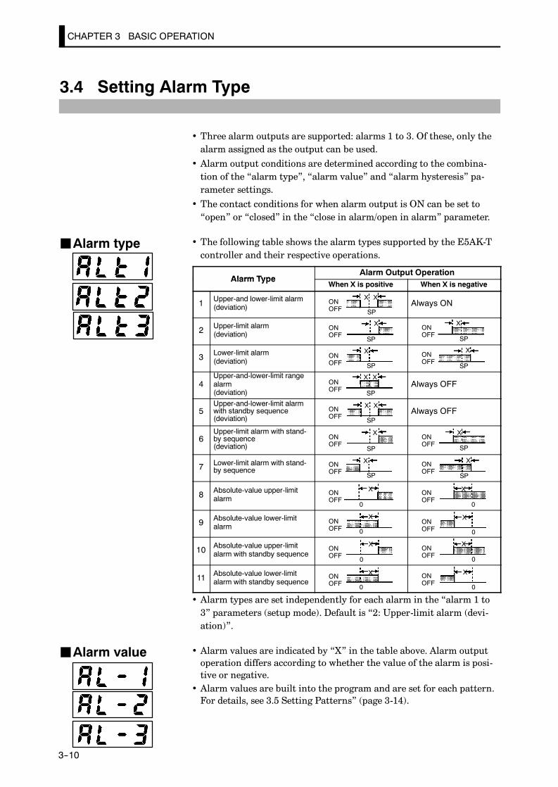
• The following table shows the alarm types supported by the E5AK-Tcontroller and their respective operations.
Alarm TypeAlarm Output Operation
Alarm TypeWhen X is positive When X is negative
1 Upper-and lower-limit alarm(deviation)
ONOFF
X X
SPAlways ON
2 Upper-limit alarm(deviation)
ONOFF
X
SP
ONOFF
X
SP
3 Lower-limit alarm(deviation)
ONOFF
X
SP
XONOFF
SP
4Upper-and-lower-limit rangealarm(deviation)
ONOFF
X X
SPAlways OFF
5Upper-and-lower-limit alarmwith standby sequence(deviation)
ONOFF
X X
SPAlways OFF
6Upper-limit alarm with stand-by sequence(deviation)
ONOFF
X
SP
ONOFF
X
SP
7 Lower-limit alarm with stand-by sequence
ONOFF
X
SP
ONOFF
X
SP
8 Absolute-value upper-limitalarm
ONOFF
X
0
ONOFF
X
0
9 Absolute-value lower-limitalarm
ONOFF
X
0ONOFF
X
0
10 Absolute-value upper-limitalarm with standby sequence
ONOFF
X
0
ONOFF
X
0
11 Absolute-value lower-limitalarm with standby sequence
ONOFF
X
0
ONOFF
X
0
• Alarm types are set independently for each alarm in the “alarm 1 to3” parameters (setup mode). Default is “2: Upper-limit alarm (devi-ation)”.
• Alarm values are indicated by “X” in the table above. Alarm outputoperation differs according to whether the value of the alarm is posi-tive or negative.
• Alarm values are built into the program and are set for each pattern.For details, see 3.5 Setting Patterns” (page 3-14).
JAlarm type
JAlarm value

3.4 Setting Alarm Type
E5AK
3--11
• The hysteresis of alarm outputs when alarms are switched ON/OFFcan be set as follows:
ON
OFF
Alarm hysteresis
Alarm value Alarm value
ON
OFF
Upper limit alarm Lower limit alarm
Alarm hysteresis
• Alarm hysteresis is set independently for each alarm in the “alarm 1to 3 hysteresis” parameters (level 2 mode). Default is “0.02:0.02%FS”.
• “Standby sequence” is a function for unconditionally turning alarmoutput OFF when the process value has left the alarm range once andit next enters the alarm range.
• For example, when the alarm type is set to “ lower-limit alarm,” gen-erally the process value is within the alarm range, and alarm outputsmaller than the set point, and alarm output becomes ON when thisstate continues. However, if the alarm type is set to “ lower-limitalarm with standby sequence”, alarm output first becomes ON whenthe process value exceeds the alarm setting value to leave the alarmrange and once again falls below the alarm value.
• The standby sequence is canceled when an alarm is output. It is, how-ever, restarted later by one of the following conditions:
Operation is started or power is turned ON.A pattern is started.The program advances to the next step.The SP of the current step is changed.The currently running alarm value is changed.The input shift value is changed.Advance is executed.
JClose in alarm/open in alarm• When the controller is set to “close in alarm,” the status of the alarmoutput function is output as it is. When set to “open in alarm,” thestatus of the alarm output function is output inverted.
Alarm Output Output LED
Close in alarmON ON Lit
Close in alarmOFF OFF Not lit
Open in alarmON OFF Lit
Open in alarmOFF ON Not lit
• Alarm type and close in alarm (normally open)/open in alarm (nor-mally close) can be set independently for each alarm.
• Close in alarm/open in alarm is set in the “alarm 1 to 3 open inalarm” parameters (setup mode). Default is “ : close in alarm”.
JAlarm hysteresis
F Standbysequence

CHAPTER 3 BASIC OPERATION
E5AK
3--12
The figure below visually summarizes the above descriptions of alarmoperations (when alarm type is set to “lower-limit alarm with standbysequence”):
Alarm type: lower limit alarm withstandby sequence
Alarm value
Alarm
Standby sequencecanceled
PV
Alarm hysteresis
Time
ON
OFF (open)output
ON (closed)
OFF
F Summary ofalarm operations
3.4 Setting Alarm Type
E5AK
3--13
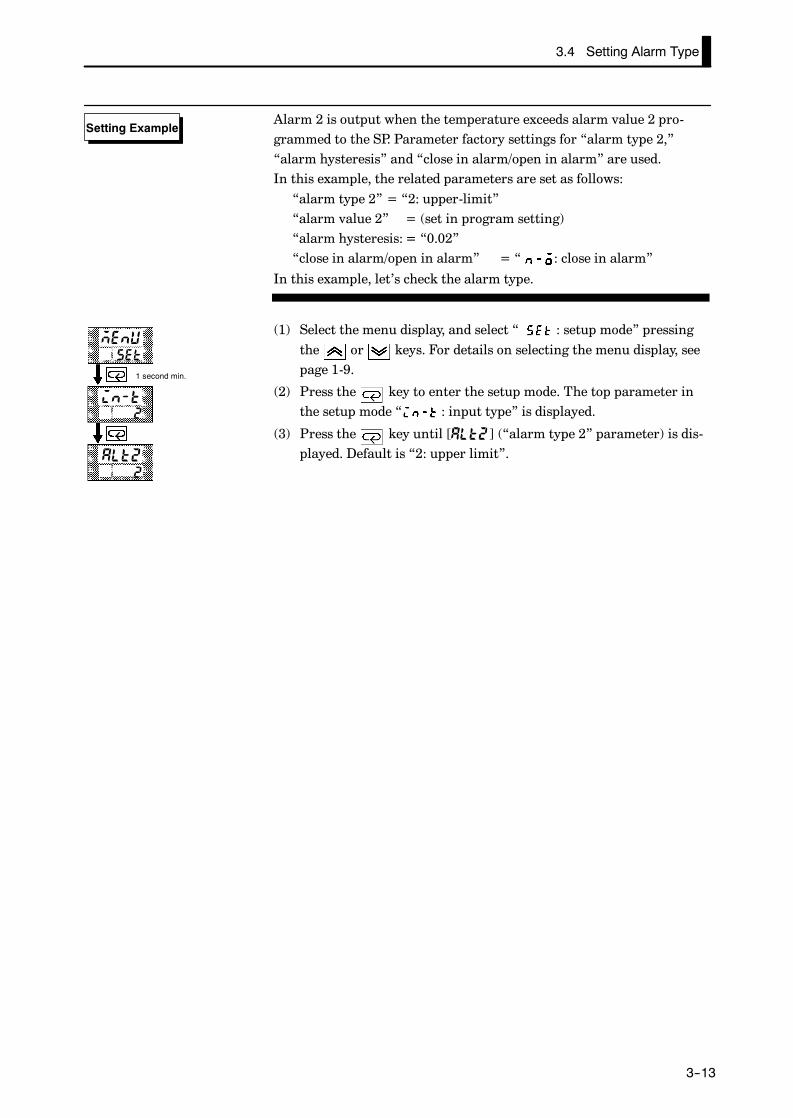
Alarm 2 is output when the temperature exceeds alarm value 2 pro-grammed to the SP. Parameter factory settings for “alarm type 2,”“alarm hysteresis” and “close in alarm/open in alarm” are used.In this example, the related parameters are set as follows:“alarm type 2” = “2: upper-limit”“alarm value 2” = (set in program setting)“alarm hysteresis: = “0.02”“close in alarm/open in alarm” = “ : close in alarm”
In this example, let’s check the alarm type.
(1) Select the menu display, and select “ : setup mode” pressingthe or keys. For details on selecting the menu display, seepage 1-9.
(2) Press the key to enter the setup mode. The top parameter inthe setup mode “ : input type” is displayed.
(3) Press the key until [ ] (“alarm type 2” parameter) is dis-played. Default is “2: upper limit”.
Setting Example
1 second min.
1 second min.
1 second min.

CHAPTER 3 BASIC OPERATION
E5AK
3--14
3.5 Setting Patterns
If you want to set parameters in the program mode during controller operation, you must first stop op-eration. Operation may continue only in special instances, for example, to change SP during controlleroperation.
• Parameters that you use frequently for programming can be set in the“program mode.” The flow below shows the parameters that areavailable in the program mode and the order in which they are set.
Select the program mode.
Select pattern No.
Set number of steps
Step time/Rate of riseprogramming
Set step SP/step time
Set pattern execution count
Set alarm value
Set time signal 1, 2Step/ON time/OFF time
All patterns completed?
End of program
Set SP/Ramp time/Soak time of each step
Step time setting
n
y
Rate of rise setting
This chapter describes the basic operation of programming. For detailson the following parameters, refer to Chapter 4 Applied Operation:
“Step time/Rate of rise programming”, “Pattern execution count”,“Time signal 1, 2”

3.5 Setting Patterns
E5AK
3--15
• This parameter cannot be changed during controller operation.• Set the desired pattern No. Step SP, step time, alarms and other pa-rameters that follow this parameter are set for the pattern that is setin this parameter.
• Set within the range 0 to 7 (pattern 0 to 7). Default is “0”.
• Set the number of steps for the pattern that you specified in the “pat-tern No.” parameter.
• Set within the range 1 to 16 (step). Default is “8”.
• Set only the number of steps used in the program in order from step0, as “step 0 SP”, “step 0 time”, “step 1 SP”, “step 1 time” and soforth.
• Set within the range from set point lower limit to set point upperlimit for step SP. Default is “0”.
• Set within the range 0.00 to 99.59 (hours:minutes or minutes:se-conds). Default is “0.00”.
Step 0 time
SP
Step 1 time Step 2 time Step 3 time
Step 0 Step 1 Step 2 Step 3
TimeA: SP of steps 0 and 3B: SP of steps 1 and 2
B
A
• As shown in the above figure, step 0 is a fixed value, so when rampoperation is started, set the “step 0 time” parameter to “0.00” to con-figure the program so that ramp operation starts from step 1.
JPattern No.
JNumber of steps
JStep SP/Steptime
:
:
: : 0 to 15

The decimal point of the alarm value conforms to the setting of the “decimalpoint” parameter.
About the AlarmValue DecimalPoint
CHAPTER 3 BASIC OPERATION
E5AK
3--16
• Alarm values can be set only for alarms that have been assigned asoutput.
• When a deviation alarm is assigned as output, the alarm value is setwith respect to SP. The following example shows the relationship be-tween the SP and alarm value when the alarm type is set to “upperlimit.”
SP
Step 0 Step 1 Step 2
Step 1 SP
Step 0 SP
Alarm type: upper-limit alarm
Alarm value
Time
JAlarm value
:
: : 0 to 3
3.5 Setting Patterns
E5AK
3--17
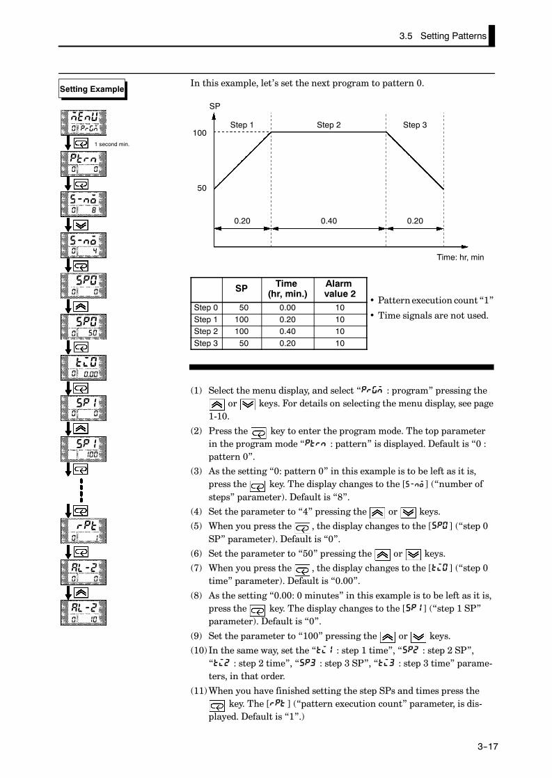
In this example, let’s set the next program to pattern 0.
Step 1 Step 2 Step 3
Time: hr, min
0.20 0.40 0.20
50
100
SP
SP Time(hr, min.)
Alarmvalue 2
Step 0 50 0.00 10Step 1 100 0.20 10Step 2 100 0.40 10Step 3 50 0.20 10
(1) Select the menu display, and select “ : program” pressing theor keys. For details on selecting the menu display, see page
1-10.
(2) Press the key to enter the program mode. The top parameterin the program mode “ : pattern” is displayed. Default is “0 :pattern 0”.
(3) As the setting “0: pattern 0” in this example is to be left as it is,press the key. The display changes to the [ ] (“number ofsteps” parameter). Default is “8”.
(4) Set the parameter to “4” pressing the or keys.
(5) When you press the , the display changes to the [ ] (“step 0SP” parameter). Default is “0”.
(6) Set the parameter to “50” pressing the or keys.
(7) When you press the , the display changes to the [ ] (“step 0time” parameter). Default is “0.00”.
(8) As the setting “0.00: 0 minutes” in this example is to be left as it is,press the key. The display changes to the [ ] (“step 1 SP”parameter). Default is “0”.
(9) Set the parameter to “100” pressing the or keys.
(10) In the same way, set the “ : step 1 time”, “ : step 2 SP”,“ : step 2 time”, “ : step 3 SP”, “ : step 3 time” parame-ters, in that order.
(11)When you have finished setting the step SPs and times press thekey. The [ ] (“pattern execution count” parameter, is dis-
played. Default is “1”.)
• Patternexecution count“1”
• Time signals are not used.
Setting Example
1 second min.

CHAPTER 3 BASIC OPERATION
E5AK
3--18
(12)As the setting in this example is to be left as it is, set the alarm val-ue. Press the key until [ ] (“alarm 2” parameter) is dis-played. Default is “0”.
(13)Set the parameter to “10: 10 seconds” pressing the orkeys.

3.6 Protect Mode
E5AK
3--19
3.6 Protect Mode
• This parameter allows you to protect until start of operation parame-ters that do not change during operation to prevent unwanted modifi-cation.
• The set value of the “security” parameter (protect mode) limits therange of protectable parameters. The following table shows the rela-tionship between set values and the range of protection. (Only modesmarked byF can be operated.)
ModeSet value
Mode0 1 2 3 4 5 6
Calibration F F
Option F F
Expansion F F
Setup F F
Level 2 F F F
Level 1 F F F F
Program F F F F F
Level 0 F F F F F F *1
*1 Only the “PV/Present SP” parameter can be displayed.
• When this parameter is set to “0”, parameters are not protected.
• When this parameter is set to “5”, operations in only the level 0 modecan be selected, and the mode is not displayed on the menu display.
• When this parameter is set to “6”, the “PV/Present SP” parametercan only be monitored.
• Default is “1”.
• This parameter disables key operation for switching run/reset orauto/manual. For example, if you protect the key operation for switch-ing auto/manual by the “key protect” parameter (protect mode) dur-ing automatic operation, the controller cannot be set to the manualmode, preventing manual operation of the controller during opera-tion.
• The following table shows the relationship between set values andkeys that are protected.
Set value Description
0 Key protection OFF1 A/M cannot be selected.2 RUN/RST cannot be selected.3 Both A/M and RUN/RST cannot be selected.
• Default is “0 : All keys can be operated.”
JSecurity
JKey protect

CHAPTER 3 BASIC OPERATION
E5AK
3--20
In this example, let’s set the parameters as follows:“Security” “2” (all parameters in modes other than the setup
mode are protected)“Key protect” “1” (Auto/manual key operation cannot be
switched)
(1) Press the RUN/RST and keys simultaneously for 1 second mini-mum. The controller enters the protect mode. In the protect mode,the top parameter in the protect mode “security” is displayed.Default is “1”.
(2) Press the key to change the parameter setting to “2”.
(3) Press the key to switch to the “key protect” parameter.
(4) Press the key to change the parameter setting to “1”.
(5) Press the and RUN/RST keys simultaneously for 1 second mini-
mum. The display changes to the “PV/Present SP monitor” parame-ter (level 0 mode).
Setting Example
RUN/RST
RUN/RST
1 second min.
1 second min.

On the E53-AKB, run/reset can be selected by event input.For details on how to use event input, see 4.8 How to Use Event Input, page 4-21.
Using Event Input
3.7 Starting and Stopping Operation
E5AK
3--21
3.7 Starting and Stopping Operation
• To start program operation (that is, switch from the reset state to run
operation), press the RUN/RST key for one second minimum.
• To stop program operation (that is, switch from run operation to the
reset state), press the RUN/RST key from two seconds minimum. When
the controller has stopped operating (reset state), the “RST” LEDlights.
• The controller cannot be reset during auto-tuning (A.T.).
• On a standard type controller, specify the manipulated variable (-5.0to 105.0%) in the “MV at reset” parameter (level 2 mode) to outputthe manipulated variable during reset. Default is “0.0:0.0%”.
• When the controller is reset in the manual mode, the manual MVtakes precedence.
• Both the MV limitter and MV change rate limitter are ineffectiveagainst the manipulated value at reset.
• On a position-proportional type controller, you can select either of theopen, closed or hold state. In an open state, only control output 1 isON. In a closed state, only control output 2 is ON. In a hold state,both control outputs 1 and 2 are OFF. Default is “ ”.
RUN/RST
F Manipulated vari-able at reset
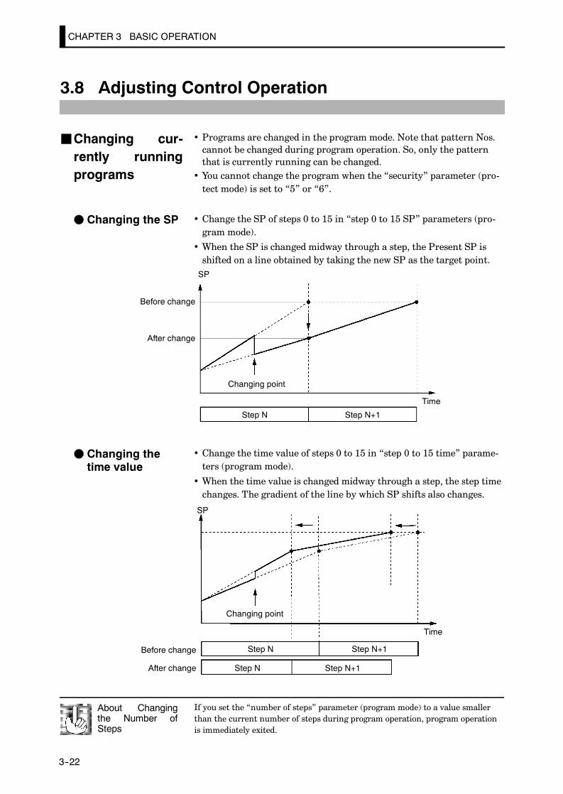
If you set the “number of steps” parameter (program mode) to a value smallerthan the current number of steps during program operation, program operationis immediately exited.
About Changingthe Number ofSteps
CHAPTER 3 BASIC OPERATION
E5AK
3--22
3.8 Adjusting Control Operation
• Programs are changed in the program mode. Note that pattern Nos.cannot be changed during program operation. So, only the patternthat is currently running can be changed.
• You cannot change the program when the “security” parameter (pro-tect mode) is set to “5” or “6”.
• Change the SP of steps 0 to 15 in “step 0 to 15 SP” parameters (pro-gram mode).
• When the SP is changed midway through a step, the Present SP isshifted on a line obtained by taking the new SP as the target point.SP
Before change
After change
Changing point
Time
Step N Step N+1
• Change the time value of steps 0 to 15 in “step 0 to 15 time” parame-ters (program mode).
• When the time value is changed midway through a step, the step timechanges. The gradient of the line by which SP shifts also changes.
SP
Changing point
Time
Step N Step N+1
Step N Step N+1
Before change
After change
JChanging cur-rently runningprograms
F Changing the SP
F Changing thetime value

3.8 Adjusting Control Operation
E5AK
3--23
In the following example, let’s change the temperature set point to“60_C” from “50_C”.
(1) Press the key for 1 second minimum at the currently executing“PV/Present SP” display.
(2) The display changes to the menu display.
(3) Set the parameter to “ : program” pressing the orkeys.
(4) Press the key to enter the program mode. The top parameterin the program mode “ : pattern” is displayed.
(5) Press the key to display the [ ] (“number of steps” parame-ter).
(6) Press the key. [ ] (“step 0 SP” parameter) is displayed, andthe No.2 display indicates “50.0”.
(7) Press the key to set the parameter to ”60.0”.
(8) Press the key for 1 second minimum. The menu display(“ : program” parameter) is redisplayed.
(9) Select “ : level 0 mode” pressing the or keys, andpress the key for 1 second minimum. The “PV/Present SP”display is redisplayed.
Setting Example
1 second min.
1 second min.
1 second min.
1 second min.

To prevent sudden changes in the manipulated variable when switching betweenmanual and auto operation, operation is resumed using the value that was activeimmediately before operation was switched, and the value is brought graduallycloser to the value immediately after operation was switched.
Balance-less,Bump-less Opera-tion
CHAPTER 3 BASIC OPERATION
E5AK
3--24
• On a standard type controller, the manipulated variable is controlled,and on a position-proportional type controller, the valve opening iscontrolled.
• To set manual operation and manually set the manipulated variableor the valve opening, press the key and key simultaneouslyfor 1 second minimum. Then the controllers enters the manual mode.To quit the manual mode, press the key and key again simul-taneously for 1 second minimum. The controller enters the level 0mode without entering the menu display.
• Though the control shifts to manual operation if the controller is setto the manual mode during program operation, the program ad-vances. When program operation is started in the manual mode, pro-gram also advances.
• In the manual mode, the automatic return of display mode does notwork.
• The process value is displayed on the No.1 display, and the manipu-lated variable is displayed on the No.2 display.
• To change the manipulated variable, press the or keys. Aftertwo seconds, the manipulated variable is updated to the new setting.
• When switching between manual and auto operation, the manipu-lated variable is subject to balance-less, bump-less operation.
• If the power is interrupted during manual operation, manual opera-tion is resumed at the manipulated variable that was active at powerinterruption when the power is reset.
0
Manipulated variable (%)Balance-less,
bump-less points
Manual
Auto
Manipulated vari-able switched OFF ON
Time
+ +
Power inter-ruption
• When a potentiometer is connected to the controller, the process valueis displayed on the No.1 display, and the valve opening is displayed onthe No.2 display.
• When you press the key, the open side becomes ON. When youpress the key, the close side becomes ON.
JManual operation
F Standard type
F Position-propor-tional type

3.8 Adjusting Control Operation
E5AK
3--25
• AT (auto-tuning) cannot be executed while operation is reset or dur-ing ON/OFF control.
• When you execute auto-tuning, the optimum PID parameters are au-tomatically set by forcibly changing the manipulated variable to cal-culate the characteristics (called the “limit cycle method”) of the con-trol target. During auto-tuning, time counting is stopped and the“AT” LED flashes.
• 40%AT or 100%AT can be selected by the limit cycle of MV changewidth. Specify [ ] or [ ], respectively, in the “AT execute/cancel” parameter (level 1 mode).
• During heating and cooling control on a standard type controller, andon a position-proportional type controller, only 100%AT can beexecuted. (So, “ : 40%AT” is not displayed.)
• To cancel AT execution, specify “ : AT cancel”.
In order to set the limit cycle of MV change width to 40%, select 40%ATto execute auto-tuning with fluctuations in the process value kept to aminimum. However, note that auto-tuning takes longer to executecompared with 100%AT.The timing by which limit cycles are generated varies according to wheth-er or not the deviation (DV) at the start of AT execution is 10% full-scaleor less.
Deviation at start of ATexecution≧ 10% FS
Deviation at start of ATexecution < 10% full-scale
Limit cycle of MV changewidth 40%
Limit cycle of MV changewidth 40%
Set point Set point
Start of ATexecution
End of ATexecution
Start of ATexecution
End of ATexecution
Time Time
Deviation 10%full-scale
Deviation 10%full-scale
In order to set the limit cycle of MV change width to 100%, select100%AT to shorten the AT execution time without worrying about fluc-tuations in the process value.
Set point
Start of ATexecution
End of ATexecution
Time
Limit cycle of MVchange width 100%
JAuto-tuning(A.T.)
F 40%AT
F 100%AT
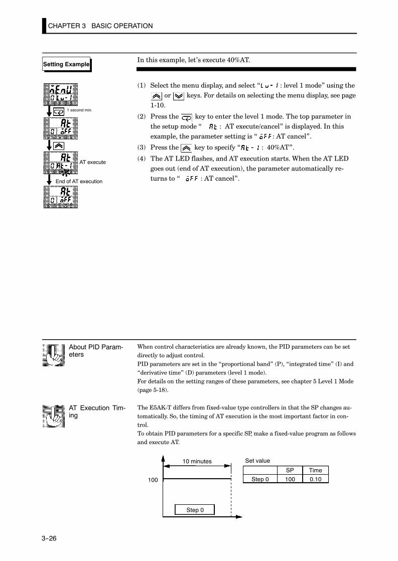
When control characteristics are already known, the PID parameters can be setdirectly to adjust control.PID parameters are set in the “proportional band” (P), “integrated time” (I) and“derivative time” (D) parameters (level 1 mode).For details on the setting ranges of these parameters, see chapter 5 Level 1 Mode(page 5-18).
About PID Param-eters
The E5AK-T differs from fixed-value type controllers in that the SP changes au-tomatically. So, the timing of AT execution is the most important factor in con-trol.To obtain PID parameters for a specific SP, make a fixed-value program as followsand execute AT.
AT Execution Tim-ing
10 minutes
100
Step 0
Set value
Step 0 100 0.10
SP Time
CHAPTER 3 BASIC OPERATION
E5AK
3--26
In this example, let’s execute 40%AT.
(1) Select the menu display, and select “ : level 1 mode” using theor keys. For details on selecting the menu display, see page
1-10.
(2) Press the key to enter the level 1 mode. The top parameter inthe setup mode “ : AT execute/cancel” is displayed. In thisexample, the parameter setting is “ : AT cancel”.
(3) Press the key to specify “ : 40%AT”.
(4) The AT LED flashes, and AT execution starts. When the AT LEDgoes out (end of AT execution), the parameter automatically re-turns to “ : AT cancel”.
Setting Example
End of AT execution
1 second min.
AT execute

CHAPTER 4 APPLIED OPERATION
E5AK
4--1
CHAPTER 4APPLIED OPERATION
This chapter describes each of the parameters required for makingfull use of the features of the E5AK-T.Read this chapter while referring to the parameter descriptions inchapter 5.
CHAPTER4
4.1 Selecting the Control Method 4-2. . . . . . . . . . . .Heating and cooling control 4-2. . . . . . . . . . . . .Position-proportional control 4-4. . . . . . . . . . . .ON/OFF control 4-5. . . . . . . . . . . . . . . . . . . . . . .
4.2 Operating Condition Restrictions 4-7. . . . . . . .Manipulated variable restrictions 4-7. . . . . . . .Set point limiter 4-8. . . . . . . . . . . . . . . . . . . . . . .
4.3 Ramp Rise Rate Setup Program 4-9. . . . . . . . .Running the ramp rise rate setup program 4-11Program example 4-12. . . . . . . . . . . . . . . . . . . . . .
4.4 Program Operation 4-13. . . . . . . . . . . . . . . . . . . .Hold/Advance 4-13. . . . . . . . . . . . . . . . . . . . . . . . . .Pattern operation 4-14. . . . . . . . . . . . . . . . . . . . . .
4.5 Wait Operation 4-16. . . . . . . . . . . . . . . . . . . . . . . .4.6 Program output 4-17. . . . . . . . . . . . . . . . . . . . . . . .
Time signal 4-17. . . . . . . . . . . . . . . . . . . . . . . . . . . .Program output 4-18. . . . . . . . . . . . . . . . . . . . . . . .
4.7 Setting Running Conditions 4-19. . . . . . . . . . . . .Operation at power ON 4-19. . . . . . . . . . . . . . . . .Starting the program run 4-19. . . . . . . . . . . . . . .End condition 4-20. . . . . . . . . . . . . . . . . . . . . . . . .
4.8 How to Use Event Input 4-21. . . . . . . . . . . . . . . .Input assignments 4-21. . . . . . . . . . . . . . . . . . . . .Detailed description of input functions 4-22. . .
4.9 How to Use the Heater Burnout Alarm 4-23. . .Heater burnout detection 4-23. . . . . . . . . . . . . . .Operating conditions 4-23. . . . . . . . . . . . . . . . . . .How to calculate the heater burnoutset value 4-24. . . . . . . . . . . . . . . . . . . . . . . . . . . . . .
4.10 LBA 4-26. . . . . . . . . . . . . . . . . . . . . . . . . . . . . . . . . .4.11 How to Use Transfer Output 4-28. . . . . . . . . . . .
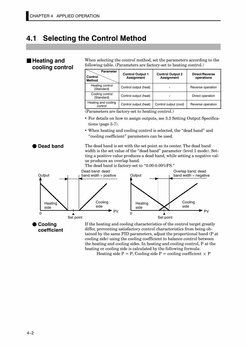
CHAPTER 4 APPLIED OPERATION
E5AK
4--2
4.1 Selecting the Control Method
When selecting the control method, set the parameters according to thefollowing table. (Parameters are factory-set to heating control.)
Parameter
ControlMethod
Control Output 1Assignment
Control Output 2Assignment
Direct/Reverseoperations
Heating control(Standard) Control output (heat) - Reverse operation
Cooling control(Standard) Control output (heat) - Direct operation
Heating and coolingcontrol Control output (heat) Control output (cool) Reverse operation
(Parameters are factory-set to heating control.)
• For details on how to assign outputs, see 3.3 Setting Output Specifica-tions (page 3-7).
• When heating and cooling control is selected, the “dead band” and“cooling coefficient” parameters can be used.
The dead band is set with the set point as its center. The dead bandwidth is the set value of the “dead band” parameter (level 1 mode). Set-ting a positive value produces a dead band, while setting a negative val-ue produces an overlap band.The dead band is factory-set to “0.00:0.00%FS.”
0 PV 0 PV
Output OutputDead band: deadband width = positive
Overlap band: deadband width = negative
Heatingside
Heatingside
Coolingside
Coolingside
Set point Set point
If the heating and cooling characteristics of the control target greatlydiffer, preventing satisfactory control characteristics from being ob-tained by the same PID parameters, adjust the proportional band (P atcooling side) using the cooling coefficient to balance control betweenthe heating and cooling sides. In heating and cooling control, P at theheating or cooling side is calculated by the following formula:
Heating side P = P; Cooling side P = cooling coefficient¢ P
JHeating andcooling control
F Dead band
F Coolingcoefficient

4.1 Selecting the Control Method
E5AK
4--3
• In heating and cooling control, the manipulated variable output thatis output when controller operation is stopped is dependent on the setvalue of the “MV at reset” parameter (level 2 mode) in the same wayas for standard control.
• However, note that in heating and cooling control, the manipulatedvariable at the cooling side is treated as a negative value for the sakeof convenience. When the manipulated variable at reset is a negativevalue, the manipulated variable is output to only the cooling side, andwhen a positive value, the manipulated variable is output to only theheating side.Default is “0”. If the controller is operated with default, the manipu-lated variable is not output to both the heating and cooling sides.
When the overlap band is set, the bumpless function that operates when switch-ing between manual and automatic operation may not work.
Switching withManual Operation
F Manipulated vari-able at reset

CHAPTER 4 APPLIED OPERATION
E5AK
4--4
• Use the position-proportional type controller for position-proportion-al control.
• On a position-proportional type controller, control output 1 is usedfor open output, and control output 2 is used for closed output. Ac-cordingly, control outputs 1 and 2 cannot be used as output assign-ments. Special output units are already set on position-proportionaltype controllers.
• On a position-proportional type controller, the following functions aredisabled:
MV limitterP and PD control40% ATLBAHBAON/OFF control
• To change the travel time, either set in the “travel time” parameter(option mode), or execute motor calibration in the “motor calibra-tion” parameter (option mode).
• Default is “30:30 seconds.”
• The valve opening can be monitored when a potentiometer is con-nected to the controller. However, be sure to execute motor calibra-tion after connecting the potentiometer.
• Open, closed or hold can be selected as output at reset or PV error. Setthese outputs in the “MV at reset” or “MV at PV error” parameters(level 2 mode).
• Set the dead band in the “position-proportional dead band” parame-ter (level 1 mode). Default is “2.0:2.0%”.
• Set the open/close hysteresis in the “open/close hysteresis” parameter(level 2 mode).
Open/close hysteresis
Dead band
MV-Valve opening100%0-100%
OFF
ON
JPosition-propor-tional control
8
7
Open
6
5Close
17
16
15C
W
O
Potentiometer
F Travel time
F Valve openingmonitor
F Manipulated vari-able at reset/PVerror
F Other functions
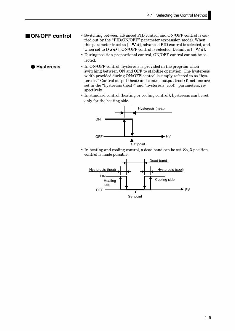
4.1 Selecting the Control Method
E5AK
4--5
• Switching between advanced PID control and ON/OFF control is car-ried out by the “PID/ON/OFF” parameter (expansion mode). Whenthis parameter is set to [ ], advanced PID control is selected, andwhen set to [ ], ON/OFF control is selected. Default is [ ].
• During position-proportional control, ON/OFF control cannot be se-lected.
• In ON/OFF control, hysteresis is provided in the program whenswitching between ON and OFF to stabilize operation. The hysteresiswidth provided during ON/OFF control is simply referred to as “hys-teresis.” Control output (heat) and control output (cool) functions areset in the “hysteresis (heat)” and “hysteresis (cool)” parameters, re-spectively.
• In standard control (heating or cooling control), hysteresis can be setonly for the heating side.
ON
OFF PV
Hysteresis (heat)
Set point
• In heating and cooling control, a dead band can be set. So, 3-positioncontrol is made possible.
ON
OFF PV
Hysteresis (heat)
Heatingside
Set point
Cooling side
Hysteresis (cool)
Dead band
JON/OFF control
F Hysteresis

CHAPTER 4 APPLIED OPERATION
E5AK
4--6
Symbol Parameter Name: Mode Description
Control output 1assignment : Setup
For specifying control method
Control output 2assignment : Setup
For specifying control method
Direct/reverseoperation : Setup
For specifying control method
Dead band : Level 1 Heating and cooling control
Cooling coefficient : Level 1 Heating and cooling control
MV at reset : Level 2 Manipulated variable when controloperation is stopped
MV at PV error : Level 2 Manipulated variable when controloperation is PV error
Travel time : Option Position-proportional control
Motor calibration : Option Position-proportional control
Positional-proportionaldead band : Level 1
Position-proportional control
Open/closehysteresis : Level 2
Position-proportional control
Hysteresis (heat) : Level 1 ON/OFF control
Hysteresis (cool) : Level 1 ON/OFF control
PID / ON/OFF : Expansion ON/OFF control
Parameters

4.2 Operating Condition Restrictions
E5AK
4--7
4.2 Operating Condition Restrictions
The upper- and lower-limit values of the manipulated variable can berestricted by the MV limitter, and the change rate of manipulated vari-able can be restricted by the MV change rate limitter.
The upper- and lower-limit values of the manipulated variable are setin the “MV upper limit” and “MV lower limit” parameters (level 2mode). When the manipulated variable calculated by the E5AK-T is out-side of the range of the MV limitter, actual outputs are dependent onthe set value of these parameters.
100
0PV
Output (%)
MV upper limit value
MV lowerlimit value
In heating and cooling control, the manipulated variable at the coolingside is treated as a negative value for the sake of convenience. The up-per limit is set for the heating side (positive value), and the lower limitis set for the cooling side (negative value) as shown in the following fig-ure.
100
0 PV
Output (%)
MV upper limit value
MV lower limit value
Heatingside
Set point
Coolingside
The “MV change rate limitter” parameter (level 2 mode) sets the maxi-mum permissible change width per second of the manipulated variable.If a change in the manipulated variable exceeds this parameter setting,the value calculated by the E5AK-T is reached while changing the valueby the per-second value set in this parameter.
100
0
Output (%)
Switching pointTime
MV change ratelimit value
1 second
JManipulated vari-able restrictions
F MV limiter
F MV change ratelimiter

CHAPTER 4 APPLIED OPERATION
E5AK
4--8
The limitters are disabled or cannot be set when any of the followingconditions occurs:
• During ON/OFF control• During AT execution (only by MV change rate limitter)• During manual operation• When operation is stopped• When an error has occurred• During position-proportional control (manipulated variable limitteronly)
The setting range of the set point is limited by the set point limitter.The upper- and lower-limit values of this set point limitter are set inthe “set point upper limit” and “set point lower limit” parameters (ex-pansion mode), respectively. However, note that when the set point li-mitter is reset, the set point is forcibly changed to the upper- or lower-limit value of the set point limitter if the set point is out of the limitterrange. Also, when the input type, temperature unit and scaling (sensor)range are changed, the set point limitter is forcibly reset to the scaling(sensor) range.
Scaling (sensor) upper-and lower-limitter values
Changed tothe new up-per limitvalue
Scaling (sensor) range
Set Point
Set point Upper-and lower-limit values of the limitter
Set point limiter
Setting range
Changed to upperlimit value
Input type changed
Set Point
A
B×
C B
(setting impossible)
(setting possible)
C
Set Point
Symbol Parameter Name: Mode Description
MV upper limit : Level 2 For limiting manipulated variable
MV lower limit : Level 2 For limiting manipulated variable
MV change rate limit : Level 2 For limiting manipulated variable
Set point upper limit : Expansion For limiting SP setting
Set point lower limit : Expansion For limiting SP setting
F Limiter operationconditions
JSet point limiter
Parameters
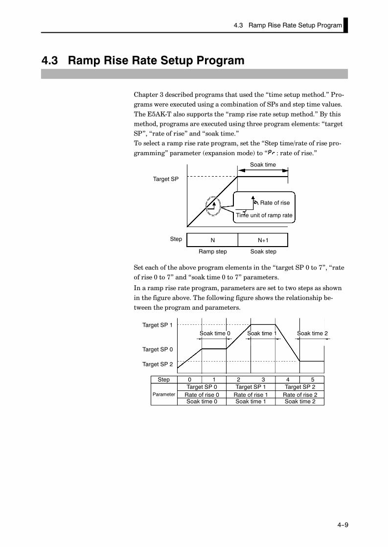
4.3 Ramp Rise Rate Setup Program
E5AK
4--9
4.3 Ramp Rise Rate Setup Program
Chapter 3 described programs that used the “time setup method.” Pro-grams were executed using a combination of SPs and step time values.The E5AK-T also supports the “ramp rise rate setup method.” By thismethod, programs are executed using three program elements: “targetSP”, “rate of rise” and “soak time.”To select a ramp rise rate program, set the “Step time/rate of rise pro-gramming” parameter (expansion mode) to “ : rate of rise.”
Target SP
Step
Ramp step Soak step
Rate of rise
Time unit of ramp rate
Soak time
N N+1
Set each of the above program elements in the “target SP 0 to 7”, “rateof rise 0 to 7” and “soak time 0 to 7” parameters.
In a ramp rise rate program, parameters are set to two steps as shownin the figure above. The following figure shows the relationship be-tween the program and parameters.
Target SP 2
Target SP 0
Target SP 1Soak time 0 Soak time 1 Soak time 2
Step
Parameter
0 1 2 3 4 5Target SP 0 Target SP 1 Target SP 2Rate of rise 0 Rate of rise 1 Rate of rise 2Soak time 0 Soak time 1 Soak time 2
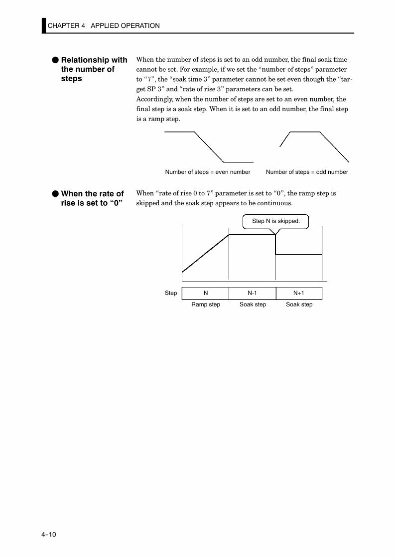
CHAPTER 4 APPLIED OPERATION
E5AK
4--10
When the number of steps is set to an odd number, the final soak timecannot be set. For example, if we set the “number of steps” parameterto “7”, the “soak time 3” parameter cannot be set even though the “tar-get SP 3” and “rate of rise 3” parameters can be set.Accordingly, when the number of steps are set to an even number, thefinal step is a soak step. When it is set to an odd number, the final stepis a ramp step.
Number of steps = even number Number of steps = odd number
When “rate of rise 0 to 7” parameter is set to “0”, the ramp step isskipped and the soak step appears to be continuous.
Step N is skipped.
Step
Ramp step Soak step
N N-1
Soak step
N+1
F Relationship withthe number ofsteps
FWhen the rate ofrise is set to “0”

4.3 Ramp Rise Rate Setup Program
E5AK
4--11
Ramp rise rate setup programs take the PV at start of program opera-tion as the SP (PV start) when they are started.
When the rate of rise is changed midway during operation, the SP rate ofrise and the step time in the ramp cycle both change.
After change
BeforechangeSwitching point
Time
Before change
After change
Step N Step N+1
Step N Step N+1
• In the above figure, increasing the rate of rise results in a shorter targetstep time. Likewise, when the SP is changed, the step time of the rampcycle also changes.
• When the soak time is changed, only the step time in the soak cyclechanges.
JRunning the ramprise rate setupprogramF Changingparameters

CHAPTER 4 APPLIED OPERATION
E5AK
4--12
Let’s describe a typical example of a ramp rise rate setup program. Inan actual program, set the parameters to match the application.
Step 0 Step 1 Step 2 Step 310
100
30 60 90 120
Target SP 0 : 100
Rate of rise 0 : 3
Soak time 0 : 0.30
Target SP 1 : 10
Rate of rise 1 : 3
Soak time 1 : 0.30
“Number of steps” = 4, “Time unit of ramp rate” = minutes, “PV start” = 10
In a program comprising four steps, steps 0 and 1 follow the settings ofthe “target SP 0”, “rate of rise 0” and “soak time 0” parameters. Steps 2and 3 follow the settings of the “target SP 1”, “rate of rise 1” and “soaktime 1” parameters.
(1) As the program starts at PV (PV start), the program starts opera-tion from “10” in this example.
(2) As the rate of rise is set to “3”, the Present SP takes 30 minutes(100-10/3=30) to reach the target SP value “100” in step 0. If thePV is “40” when the program is started, this time then becomes 20minutes using the same formula.
(3) In step 1, the Present SP does not change, and the step time is thevalue set to the “soak time 0” parameter (in this example, “30 min-utes”).
(4) In step2, the Present SP changes according to the value of “rate ofrise 1” parameter from that of “target SP 0” parameter to that of“target SP 1” parameter. It takes 30 minutes in this example.
(5) In step 3, the Present SP does not change, and the step time is thevalue set to the “soak time 1” parameter (in this example, “30 min-utes”).
Symbol Parameter Name: Mode Description
Step time/Rate of rise programming : Expansion Ramp rise rate
: Target SP 0 to 7 : Program Ramp rise rate
: Rate of rise 0 to 7 : Program Ramp rise rate: Soak time 0 to 7 : Program Ramp rise rate
: : to
By ramp rise rate setup method, starting at input error, the program start step isthe “step 1”.
Operationat Input Error
JProgram example
F Programstructure
F How the programworks
Parameters
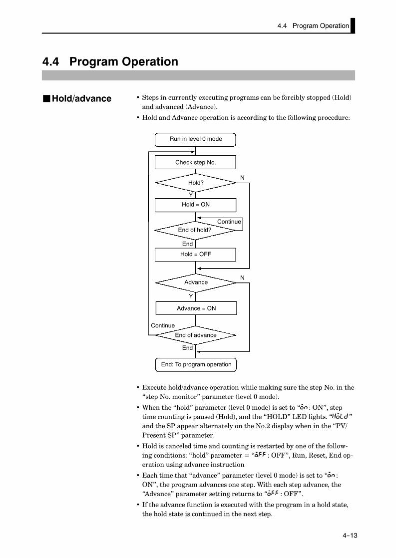
4.4 Program Operation
E5AK
4--13
4.4 Program Operation
• Steps in currently executing programs can be forcibly stopped (Hold)and advanced (Advance).
• Hold and Advance operation is according to the following procedure:
Run in level 0 mode
Check step No.
Hold?
Hold = ON
ContinueEnd of hold?
End
Hold = OFF
Advance
Advance = ON
Continue
End of advance
End
End: To program operation
Y
Y
N
N
• Execute hold/advance operation while making sure the step No. in the“step No. monitor” parameter (level 0 mode).
• When the “hold” parameter (level 0 mode) is set to “ : ON”, steptime counting is paused (Hold), and the “HOLD” LED lights. “ ”and the SP appear alternately on the No.2 display when in the “PV/Present SP” parameter.
• Hold is canceled time and counting is restarted by one of the follow-ing conditions: “hold” parameter = “ : OFF”, Run, Reset, End op-eration using advance instruction
• Each time that “advance” parameter (level 0 mode) is set to “ :ON”, the program advances one step. With each step advance, the“Advance” parameter setting returns to “ : OFF”.
• If the advance function is executed with the program in a hold state,the hold state is continued in the next step.
JHold/advance

CHAPTER 4 APPLIED OPERATION
E5AK
4--14
JPattern operation• To repeatedly execute the same pattern, set the number of times thatthe pattern is to be executed in the “pattern execution count” param-eter (program mode).
• The pattern execution count can be set up to 9999 (times). (Default is“0”.)
• Patterns for which the “pattern execution count” parameter is set to“0” cannot be executed.
• The count of the currently executing pattern in the program can beverified in the “pattern execution count monitor” parameter (level 0mode). “0” is indicated in this parameter when the controller of resetor in a standby state.
• To execute all preset patterns in order from pattern 0, set the “run allenable” parameter (expansion mode) to “ : ON”. (Default is “ :OFF”.)
Time
Pattern 0 Pattern 1 Pattern 2
• When a power interruption occurs during run all execution, if the“operation at power ON” parameter (expansion mode) is set to “ :Continue”, the currently executing pattern No. is held in memory.When power is restored, program operation resumes from the patternthat was being executed when the power was interrupted. (For detailson operation at power ON, see page 4-19.)
• Patterns whose “pattern execution count” is set to “0” are skipped.
Time
Pattern 0 Pattern 1 Pattern 3
“pattern execution count” of pattern 2 is set to 0
F Repeating execu-tion of the samepattern
F Executing allpatterns

4.4 Program Operation
E5AK
4--15
Symbol Parameter Name: Mode Description
Hold : Level 0 Pauses program execution.
Advance : Level 0 Advances the program one step.
Pattern execution count : ProgramRepeatedly executes currentpattern.
Run all :Expansion Executes all patterns.
• A reset cancels a hold state.
• When the controller is reset during run all execution, the program returnsto step 0 of the currently executing pattern.
About Reset
Parameters
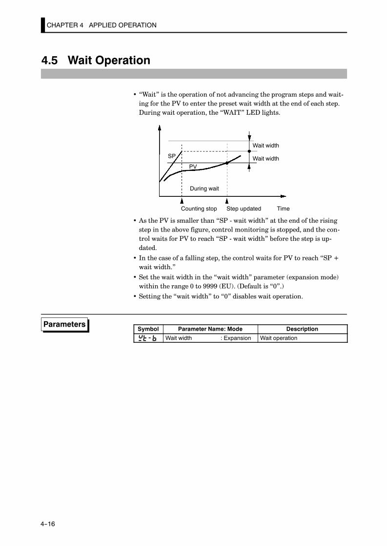
CHAPTER 4 APPLIED OPERATION
E5AK
4--16
4.5 Wait Operation
• “Wait” is the operation of not advancing the program steps and wait-ing for the PV to enter the preset wait width at the end of each step.During wait operation, the “WAIT” LED lights.
Wait width
Wait width
During wait
Counting stop Step updated Time
SP
PV
• As the PV is smaller than “SP - wait width” at the end of the risingstep in the above figure, control monitoring is stopped, and the con-trol waits for PV to reach “SP - wait width” before the step is up-dated.
• In the case of a falling step, the control waits for PV to reach “SP +wait width.”
• Set the wait width in the “wait width” parameter (expansion mode)within the range 0 to 9999 (EU). (Default is “0”.)
• Setting the “wait width” to “0” disables wait operation.
Symbol Parameter Name: Mode Description
Wait width : Expansion Wait operation
Parameters
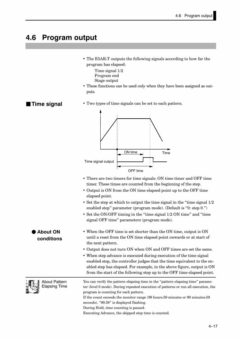
You can verify the pattern elapsing time in the “pattern elapsing time” parame-ter (level 0 mode). During repeated execution of patterns or run all execution, theprogram is counting for each pattern.If the count exceeds the monitor range (99 hours:59 minutes or 99 minutes:59seconds), “99.59” is displayed flashing.During Hold, time counting is paused.Executing Advance, the skipped step time is counted.
About PatternElapsing Time
4.6 Program output
E5AK
4--17
4.6 Program output
• The E5AK-T outputs the following signals according to how far theprogram has elapsed:
Time signal 1/2Program endStage output
• These functions can be used only when they have been assigned as out-puts.
• Two types of time signals can be set to each pattern.
Time signal output
ON time
OFF time
Time
• There are two timers for time signals: ON time timer and OFF timetimer. These times are counted from the beginning of the step.
• Output is ON from the ON time elapsed point up to the OFF timeelapsed point.
• Set the step at which to output the time signal in the “time signal 1/2enabled step” parameter (program mode). (Default is “0: step 0.”)
• Set the ON/OFF timing in the “time signal 1/2 ON time” and “timesignal OFF time” parameters (program mode).
• When the OFF time is set shorter than the ON time, output is ONuntil a reset from the ON time elapsed point onwards or at start ofthe next pattern.
• Output does not turn ON when ON and OFF times are set the same.
• When step advance is executed during execution of the time signalenabled step, the controller judges that the time equivalent to the en-abled step has elapsed. For example, in the above figure, output is ONfrom the start of the following step up to the OFF time elapsed point.
JTime signal
F About ONconditions

CHAPTER 4 APPLIED OPERATION
E5AK
4--18
JProgram status
• One-second pulse signal is output after the final step is completed.
Final step
Program end output
Time
1s
• One-second pulse signal is output at the beginning of each step.
Stage output
Time1s
Symbol Parameter Name: Mode Description: Time signal:set step : Program Time signal
: Time signal:ON time : Program Time signal: Time signal:ON time : Program Time signal: Control output:assignment : Setup Program status: Auxiliary output:assignment : Setup Program status
: : to
F Program end
F Stage output
Parameters

4.7 Setting Running Conditions
E5AK
4--19
4.7 Setting Running Conditions
• You can select from one of the following operations at power ON:Continue, Reset, Run, Manual
• If you select “Continue,” operation is started from the state that wasactive when power was interrupted.
• If you select “Reset,” the controller is reset.
• If you select “Run,” normal program operation is started.
• If you select “Manual,” the controller enters the manual mode.
• The following table shows the relationship between operation at pow-er ON and the operation details that are stored to memory when apower interruption occurs.
Continue Reset Run ManualPattern No. f f f f
Step No. f - - f
Pattern elapsing time f - - f
Pattern execution count f - - f
Hold status f - - f
Auto/Manual f f f -Run/Reset f - - f
MV at reset *1 f - - f
Manual MV *2 f f f f
*1 During auto mode at power interruption on a standard type controller
*2 During manual mode at power interruption on a standard type controller
• Set the desired operation in the “operation at power ON” parameter(expansion mode). Default is “ : Continue”.
JOperation atpower ON

CHAPTER 4 APPLIED OPERATION
E5AK
4--20
JStarting theprogram run
• When the program is configured by the time setup method, a ramp-priority “PV start” can be selected as one of the run start conditions.If you select “PV start” in the “PV start” parameter (expansionmode), program operation is started from the position of the SP thatfirst matches the PV when program run is started. If the SP does notmatch the PV, the program run is started from the beginning.
SP
PV
Step 0 Step 1 Step 2 Step 3
Disabled time
Start point
Time
• After the run instruction, the controller is reset until the standbytime elapses.
• Set the standby time in the “standby time” parameter (level 2 mode)within the range 0.00 to 99.59 (hours:minutes). Defaults is “0.00”.
• After end of operation, the controller normally is reset. However, con-trol can be continued on the SP of the final step by setting the “endcondition” parameter (expansion mode). If the “end condition” is set,the SP of the final step and [ ] appears alternately on the No.2display.
• When the “number of steps” parameter is changed after operation hasended, the controller state does not change state. However, if controlwith respect to the SP is continued, the SP switches to the new valueof the final step.
Symbol Parameter Name: Mode Description
Operation at power ON : Expansion Operation when power isturned ON
PV start : Expansion Start of program run
Standby time : Level 2 Start of program run
End condition : Expansion Operation end program run
F PV start
F Standbyoperation
JEnd condition
Parameters

4.8 How to Use Event Input
E5AK
4--21
4.8 How to Use Event Input
• When using event input, mount the option unit (E53-AKB).up to two E53-AKB units can be mounted on the E5AK-T, and twoevent input can be used for each E53-AKB unit.E53-AKB× 1 unit : 2 event inputsE53-AKB× 2 unit : 4 event inputs
• Switching by event input is not possible on the menu display.
• Switch event inputs ON and OFF while controller power is ON.
• You can choose from the following six event input functions:
Run/ResetRemote/LocalAuto/ManualHold/Hold cancelAdvancePattern select
• Event input ON/OFF judgment is carried out on inputs of 200 msminimum.
• When event inputs are used as program advance input, the programstep is advanced at the rising (OFF→ON) edge of the input signal.When event inputs are used as run/reset input, program operation isstopped (reset) at the rising (OFF→ON) edge of the input signal, andprogram operation is started (run) at the falling (ON→OFF) edge.Other signals are accepted at all times.
• Set event input assignments in the “event input assignments 1 to 4”parameters (option mode). However, note that “event input assign-ment 1/2” parameters cannot be used when only one unit of theE53-AKB is installed.
• The following table shows the relationship between the settings andfunctions of the “event input assignment 1 to 4” parameters.
Setting Function
Event input disabled
OFF→ON: Reset /ON→OFF: RunON: Remote /OFF: Local
ON: Manual /OFF: Auto
ON: Hold /OFF: Hold cancel
Execute at OFF→ON
Specify by combination of three inputs (*1).Specify by combination of three inputs ( 1).
*1 The following table shows the relationship between pattern select No. andpattern No.
Pattern No. 0 1 2 3 4 5 6 7Pattern select 0 f f f f
Pattern select 1 f f f f
Pattern select 2 f f f f
J Inputassignments
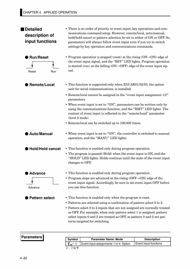
CHAPTER 4 APPLIED OPERATION
E5AK
4--22
• There is no order of priority in event input, key operations and com-munications command setup. However, remote/local, auto/manual,hold/hold cancel or pattern selection be set to either of ON or OFF. So,parameters will always follow event input even if you try to switchsettings by key operation and communications commands.
• Program operation is stopped (reset) at the rising (ON→ON) edge ofthe event input signal, and the “RST” LED lights. Program operationis started (run) at the falling (ON→OFF) edge of the event input sig-nal.
• This function is supported only when E53-AK01/02/03, the optionunit for serial communications, is installed.
• Remote/local cannot be assigned in the “event input assignment 1/2”parameters.
• When event input is set to “ON”, parameters can be written only byusing the communications function, and the “RMT” LED lights. Thecontent of event input is reflected in the “remote/local” parameter(level 2 mode).
• Remote/local can be switched up to 100,000 times.
• When event input is set to “ON”, the controller is switched to manualoperation, and the “MANU” LED lights.
• This function is enabled only during program operation.
• The program is paused (Hold) when the event input is ON, and the“HOLD” LED lights. Holds continue until the state of the event inputchanges to OFF.
• This function is enabled only during program operation.
• Program steps are advanced at the rising (OFF→ON) edge of theevent input signal. Accordingly, be sure to set event input OFF beforeyou use this function.
• This function is enabled only when the program is reset.
• Patterns are selected using a combination of pattern select 0 to 2.
• Pattern select 0 to 2 inputs that are not assigned are normally treatedas OFF. For example, when only pattern select 1 is assigned, patternselect inputs 0 and 2 are treated as OFF, so pattern 0 and 2 are pat-terns targeted for switching.
Symbol Parameter Name: Mode Description
: Event input assignments 1 to 4: Option Event input functions
: : to
JDetaileddescription ofinput functions
F Run/Reset
Reset Run
F Remote/Local
F Auto/Manual
F Hold/Hold cancel
F Advance
Advance
F Pattern select
Parameters
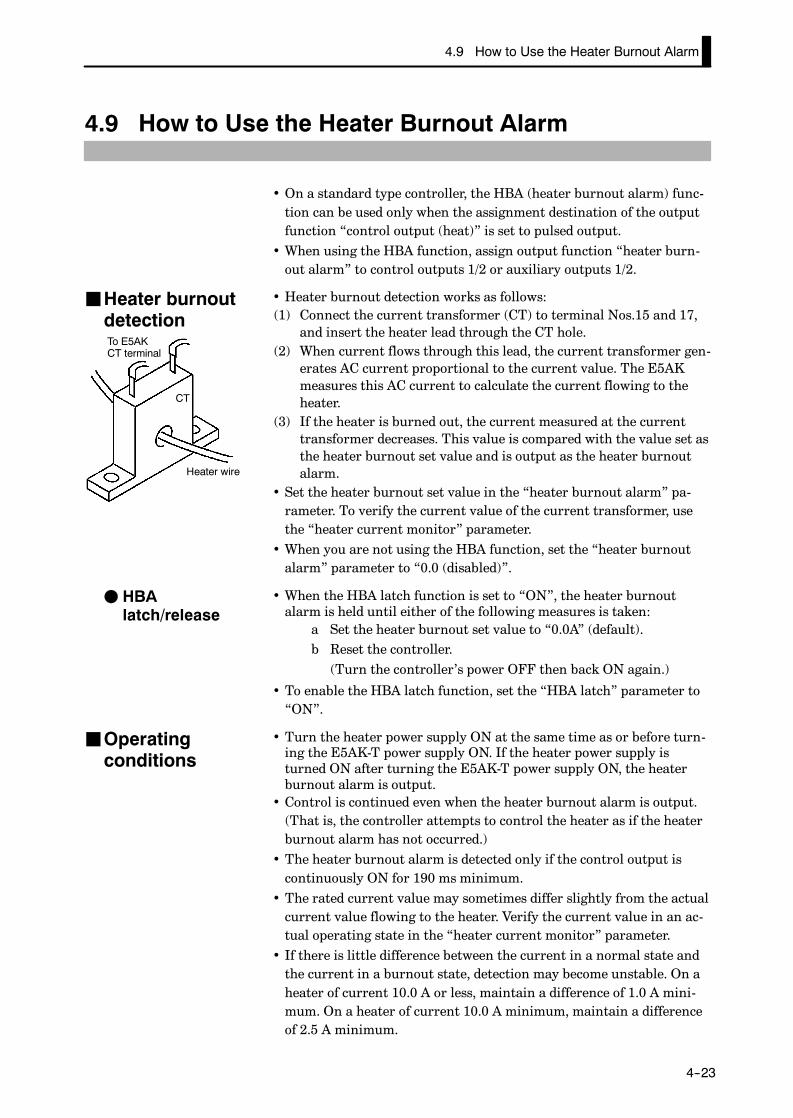
4.9 How to Use the Heater Burnout Alarm
E5AK
4--23
4.9 How to Use the Heater Burnout Alarm
• On a standard type controller, the HBA (heater burnout alarm) func-tion can be used only when the assignment destination of the outputfunction “control output (heat)” is set to pulsed output.
• When using the HBA function, assign output function “heater burn-out alarm” to control outputs 1/2 or auxiliary outputs 1/2.
• Heater burnout detection works as follows:(1) Connect the current transformer (CT) to terminal Nos.15 and 17,
and insert the heater lead through the CT hole.(2) When current flows through this lead, the current transformer gen-
erates AC current proportional to the current value. The E5AKmeasures this AC current to calculate the current flowing to theheater.
(3) If the heater is burned out, the current measured at the currenttransformer decreases. This value is compared with the value set asthe heater burnout set value and is output as the heater burnoutalarm.
• Set the heater burnout set value in the “heater burnout alarm” pa-rameter. To verify the current value of the current transformer, usethe “heater current monitor” parameter.
• When you are not using the HBA function, set the “heater burnoutalarm” parameter to “0.0 (disabled)”.
• When the HBA latch function is set to “ON”, the heater burnoutalarm is held until either of the following measures is taken:
a Set the heater burnout set value to “0.0A” (default).b Reset the controller.(Turn the controller’s power OFF then back ON again.)
• To enable the HBA latch function, set the “HBA latch” parameter to“ON”.
• Turn the heater power supply ON at the same time as or before turn-ing the E5AK-T power supply ON. If the heater power supply isturned ON after turning the E5AK-T power supply ON, the heaterburnout alarm is output.
• Control is continued even when the heater burnout alarm is output.(That is, the controller attempts to control the heater as if the heaterburnout alarm has not occurred.)
• The heater burnout alarm is detected only if the control output iscontinuously ON for 190 ms minimum.
• The rated current value may sometimes differ slightly from the actualcurrent value flowing to the heater. Verify the current value in an ac-tual operating state in the “heater current monitor” parameter.
• If there is little difference between the current in a normal state andthe current in a burnout state, detection may become unstable. On aheater of current 10.0 A or less, maintain a difference of 1.0 A mini-mum. On a heater of current 10.0 A minimum, maintain a differenceof 2.5 A minimum.
JHeater burnoutdetectionTo E5AKCT terminal
Heater wire
CT
F HBAlatch/release
JOperatingconditions

CHAPTER 4 APPLIED OPERATION
E5AK
4--24
• The heater burnout alarm function cannot be used when the heater iscontrolled by a phase control system or by a cycle control system.Also, the heater burnout alarm function cannot be applied on 3-phaseheaters.
To detect heater burnout on a 3-phase heater, use the K2CU-FjjA-jGS (withgate input terminal). (For details, see the respective product catalog.)
• Calculate the set value by the following formula:
Set value =(current value at normal operation + current value at burnout)
2
• Set the current value at burnout when two or more heaters are con-nected to the CT to the value at the time that the heater having thesmaller(est) current value burns out (the value when one of the heat-ers burns out with all heaters at the same current).
• Make sure that the following condition is satisfied:
Heater of current 10.0 A or lessCurrent value at normal operation - current value at heaterburnout≧ 1AWhen resultant current is less than 1 A, detection is unstable.Heater of current 10.0 A minimumCurrent value at normal operation - current value at heaterburnout≧ 2.5 AWhen resultant current is less than 2.5 A, detection is unstable.
• The set value can be set within the range 0.1 to 49.9 A. Heater burn-out is not detected when the setting is “0.0” or “50.0”. When the set-ting is “0.0”, the heater burnout alarm is set to “OFF,” and when thesetting is “50.0”, the heater burnout alarm is set to “ON.”
• Set the total current value at normal heater operation to 50 A or less.When set to 55.0 A minimum, [ ] is displayed in the “heater cur-rent monitor” parameter.
JHow to calculatethe heater burn-out set value

4.9 How to Use the Heater Burnout Alarm
E5AK
4--25
Example 1 : when using a 200 VAC, 1 kW heater
Current at normal operation =1000200
= 5A (< 10A)
Current at heater burnout = 0A
Set value =5+02
= 2.5A
(current at normal operation-current at heater burnout= 5 - 0 = 5A (≧ 1A)
Example 2 : when using three 200 VAC, 1 kW heaters
Set value =
Current at normal operation =1000200
×3 = 15A (≧ 10A)
Current at burnout of one heater =1000200
×2 = 10A
15+102
= 12.5A
(current at normal operation-current at heater burnout= 15 - 10 = 5A (≧ 2.5A)
Symbol Parameter Name: Mode Description
Heater current monitor : Level 1 Heater current value monitor
Heater burnout detection : Level 1 Heater burnout detection
Heater burnout latch : Option Heater burnout detection alarm latch
F Examples of use
15
Control output
17
Heater
1KWAC200V
CT
E5AK-T
15
Control output
17
Heater
1KWx3AC200V
CT
E5AK-T
Parameters

CHAPTER 4 APPLIED OPERATION
E5AK
4--26
4.10 LBA
• The LBA (Loop Break Alarm) function can be used only on standardtype controllers.
• The LBA function can be used only when it is assigned as an output.Also, the LBA function does not work when a memory error or A/Dconverter error results.
• LBA (Loop Break Alarm) is a function for judging that an error hasoccurred somewhere on the control loop and for outputting an alarmwhen the process value does not change with the manipulated vari-able at a maximum or minimum state. Accordingly, the LBA functioncan be used as a means for detecting a malfunctioning control loop.
• Normally, when output is set to maximum or minimum, the processvalue rises or falls after the dead time has elapsed. LBA is output ifthe process value does not change in the predicted direction after afixed amount of time has elapsed. This fixed amount of time is the“LBA detection time.”
• LBA operation sometimes becomes unstable when the process valuefluctuates considerably due to the control characteristics. The LBAdetection width is provided so that changes with respect to output canbe correctly detected. Changes smaller than the detection width dueto LBA detection timing are not regarded as changes.
• The following example describes what happens when a heater burn-out occurs at maximum output.
PV
LBA=ON
LBA detection time
LBA detection width
Output
Time
Heater burnout
LBA detection time
• LBA judgment is carried out at each LBA detection time from thepoint of maximum output. In the above figure, the process value (PV)is changing greatly at the 1st judgment time band, so LBA remainsOFF.
• At the 2nd judgment time band, the process value increases as indi-cated by the broken line if the process value is normal. This meansthat the change width exceeds the LBA detection width, and LBA out-put remains OFF.
• If the heater burns out at the point shown in the above figure, theprocess value “decreases.” Accordingly, it is judged that “the processvalue is not changing in the increasing direction” at the 2nd judg-ment time band and the LBA output becomes ON.
F LBA detectiontime
F LBA detectionwidth
F LBA detectionexample
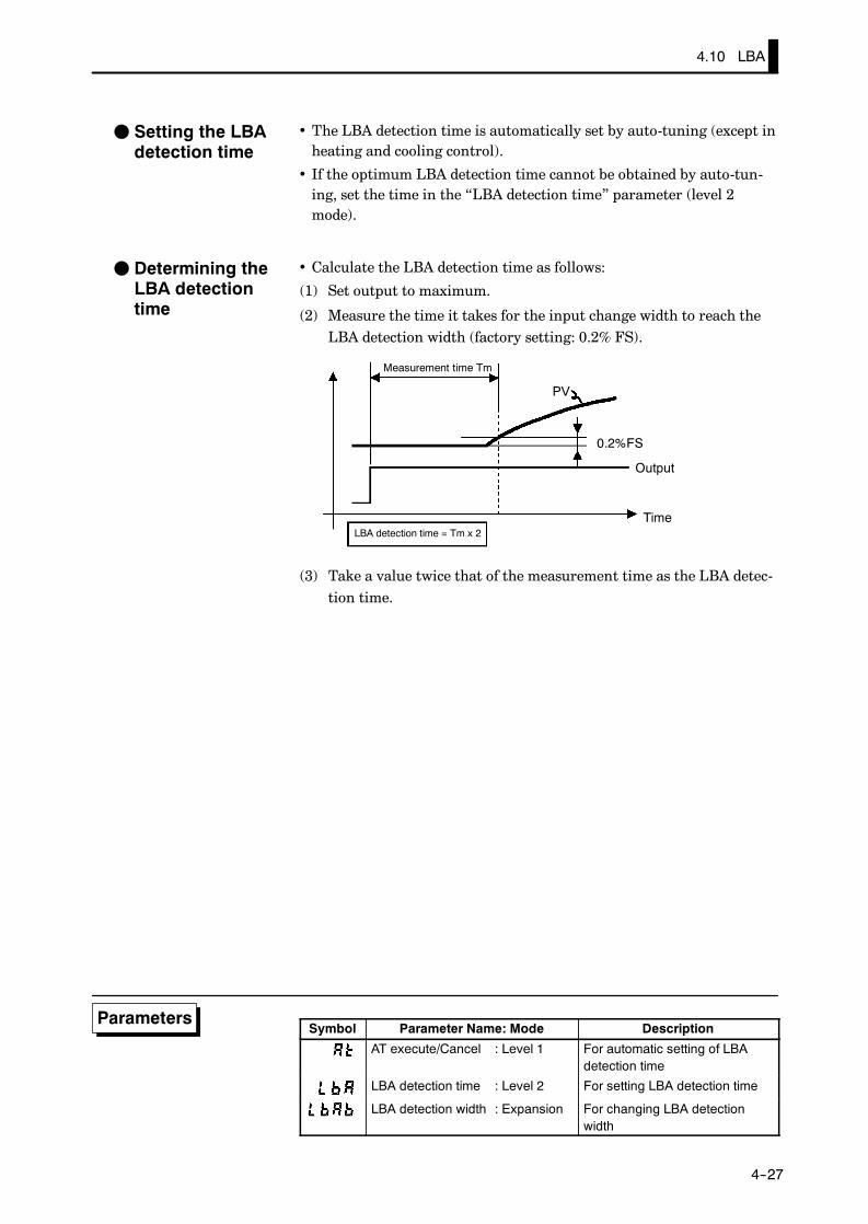
4.10 LBA
E5AK
4--27
• The LBA detection time is automatically set by auto-tuning (except inheating and cooling control).
• If the optimum LBA detection time cannot be obtained by auto-tun-ing, set the time in the “LBA detection time” parameter (level 2mode).
• Calculate the LBA detection time as follows:
(1) Set output to maximum.
(2) Measure the time it takes for the input change width to reach theLBA detection width (factory setting: 0.2% FS).
PV
0.2%FS
Measurement time Tm
LBA detection time = Tm x 2
Output
Time
(3) Take a value twice that of the measurement time as the LBA detec-tion time.
Symbol Parameter Name: Mode Description
AT execute/Cancel : Level 1 For automatic setting of LBAdetection time
LBA detection time : Level 2 For setting LBA detection time
LBA detection width : Expansion For changing LBA detectionwidth
F Setting the LBAdetection time
F Determining theLBA detectiontime
Parameters

CHAPTER 4 APPLIED OPERATION
E5AK
4--28
4.11 How to Use Transfer Output
• When using transfer output, add on the communications unit(E53-AKF).
• You can select the following five data items in the “transfer outputtype” parameter (option mode) as the transfer outputs:Present SP (default), Process value, Manipulated variable (heat),Manipulated variable (cool), Valve opening
However, note that heating/cooling side manipulated variables can beoutput only on standard type controllers, and valve opening can beoutput on position-proportional type controllers.
• If the output assignment is changed when either the “manipulatedvariable (heat)” or “manipulated variable (cool)” parameter is se-lected, the factory setting “set point” is returned to.
• These transfer outputs can be scaled according to the settings of the“transfer output upper limit” and “transfer output lower limit” pa-rameters before output. Setting of an upper limit value smaller thanthe lower limit value is allowed, so reverse scaling can also be carriedout. Also, the scale can be enlarged by the upper- and lower-limitwidth specified for each data item. The following example shows scal-ing of the heating side manipulated variable.
(mA)
20
4
20
4
0100
(mA)Transfer output Transfer output
Reverse scaling Enlarged scale
Transfer outputupper limit: 0
Transferoutput lowerlimit: 100
Manipu-latedvariable(%)
Transferoutput lowerlimit: 10
Transferoutput upperlimit: 80
Manipulatedvariable (%)
Symbol Parameter Name: Mode Description
Transfer output type : Option Transfer output designation
Transfer output upper limit : Option Transfer output scaling
Transfer output lower limit : Option Transfer output scaling
F Transfer outputtype
F Transfer outputscaling
Parameters

CHAPTER 5 PARAMETERS
E5AK
5--1
CHAPTER 5PARAMETERS
This chapter describes the parameters of the E5AK-T.Use this chapter as a reference guide.
CHAPTER5
Conventions Used in this Chapter 5-2. . . . . . . . . . . .
Protect Mode 5-3. . . . . . . . . . . . . . . . . . . . . . . . . . . . . . .
Manual Mode 5-5. . . . . . . . . . . . . . . . . . . . . . . . . . . . . .
Level 0 Mode 5-6. . . . . . . . . . . . . . . . . . . . . . . . . . . . . . .
Program Mode 5-11. . . . . . . . . . . . . . . . . . . . . . . . . . . . .
Level 1 Mode 5-17. . . . . . . . . . . . . . . . . . . . . . . . . . . . . . .
Level 2 Mode 5-24. . . . . . . . . . . . . . . . . . . . . . . . . . . . . . .
Setup Mode 5-30. . . . . . . . . . . . . . . . . . . . . . . . . . . . . . . .
Expansion Mode 5-38. . . . . . . . . . . . . . . . . . . . . . . . . . . .
Option Mode 5-46. . . . . . . . . . . . . . . . . . . . . . . . . . . . . . .
Calibration Mode 5-52. . . . . . . . . . . . . . . . . . . . . . . . . . .

CHAPTER 5 PARAMETERS
E5AK
5--2
JThe meaning of icons used in this chapter
Describes the functions of the parameter.
Describes the range and defaults of the parameter setting.
Used for monitor-dedicated parameters.Describes the range of the monitor values.
Describes a procedure using parameters in operating instructions.
Describes related parameters and items.
Describes models of the E5AK-T or optional units that support the parameter beingdescribed.
JAbout parameter displayOn the E5AK-T controller, only parameters that can be used are displayed. These parameters aredisplayed only when the “Conditions of Use” on the right of the parameter heading are satisfied.However, note that the settings of protected parameters are still valid, and are not displayedregardless of the conditions of use.
Conditions of UseThe controller mustbe in operation.
AT Execute/cancel
JAbout the Order in Which Parameters Described in This ChapterParameters are described mode by modeThe first page of each mode lists the parameters available in that mode. The parameternames in these contents are listed in the order that they are displayed on the controller.
Conventions Used in this Chapter
Function
Setting
Monitor
Exampleof use
See
Model

E5AK
5--3
• The protect function restricts key use to prevent unwanted key operation. Beforechanging parameters in this mode, first make sure that protecting the keys willnot cause any problems in operation.
• To select this mode, press the RUN/RST and keys simultaneously for 1 secondminimum. To exit this mode, press the RUN/RST and keys simultaneouslyagain for 1 second minimum.
• The following table shows the parameters supported in this mode and the pagewhere the parameter is described.
Symbol Parameter Name PageSecurity 5-3Key protect 5-4
Security
• This parameter specifies which parameters are protected. Note that the protectmode and manual mode cannot be protected.
• Only the modes indicated by the “F” mark in the table below can be selected onthe menu display. For example, when this parameter is set to “3”, only levels 0 and1 and the program mode can be selected.
ModeSetting value
Mode0 1 2 3 4 5 6
Calibration F
Option F F
Expansion F F
Setup F F
Level 2 F F F
Level 1 F F F F
Program F F F F F
Level 0 F F F F F F *1
*1 The “PV/Present SP” parameter is only displayed.
• When this parameter is set to “0”, the protection function is disabled.
• When this parameter is set to “5”, only the parameters in the level 0 mode can beused, and the menu display is not selected.
• When this parameter is set to “6”, “PV/Present SP” parameter can only be dis-played. (The set point cannot be changed.)
• Default is “1”. (Only the calibration mode is protected.)
F Related description3.6 Protect Mode (page 3-19)
Protect Mode
Function
Setting
See
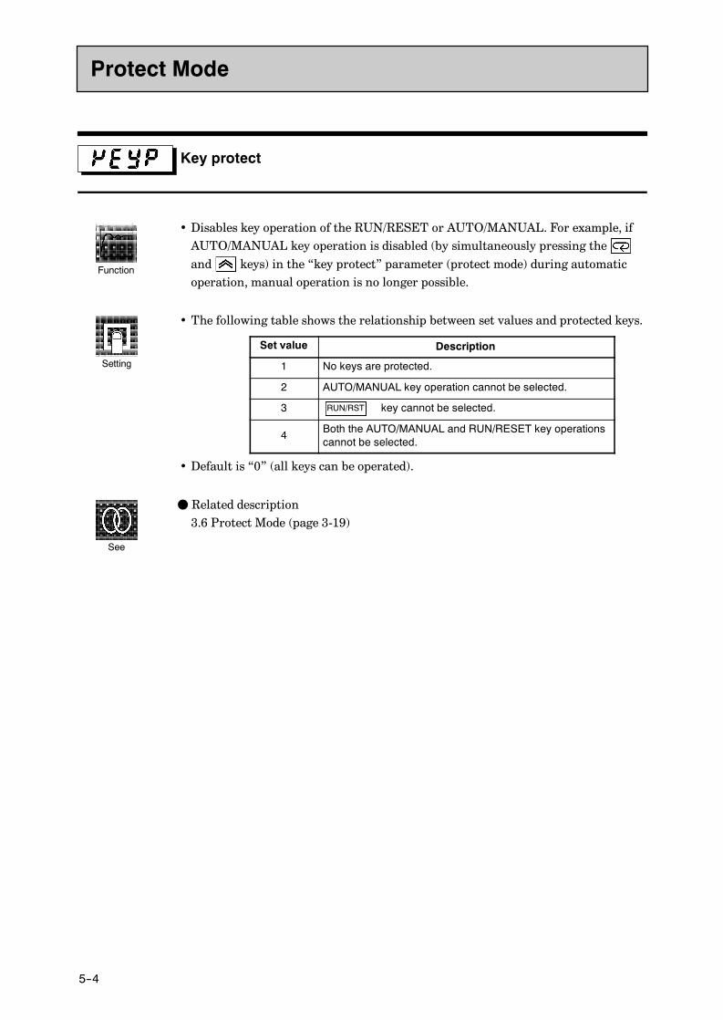
CHAPTER 5 PARAMETERS
E5AK
5--4
Key protect
• Disables key operation of the RUN/RESET or AUTO/MANUAL. For example, ifAUTO/MANUAL key operation is disabled (by simultaneously pressing theand keys) in the “key protect” parameter (protect mode) during automaticoperation, manual operation is no longer possible.
• The following table shows the relationship between set values and protected keys.
Set value Description
1 No keys are protected.
2 AUTO/MANUAL key operation cannot be selected.
3 “RUN/RST” key cannot be selected.RUN/RST
4 Both the AUTO/MANUAL and RUN/RESET key operationscannot be selected.
• Default is “0” (all keys can be operated).
F Related description3.6 Protect Mode (page 3-19)
Protect Mode
Function
Setting
See

E5AK
5--5
• In this mode, manual operation is possible, and the “MANU” LED lights.
• When this mode is selected, the manipulated variable that was active immediatelybefore the mode was switched to is output. To change the manipulated variable,use the or keys. If this mode is switched to during auto-tuning, auto-tun-ing is canceled.
• To select this mode when in the level 0 to 2 modes, press the and keyssimultaneously for 1 second minimum. To exit this mode, press the andkeys simultaneously again for 1 second minimum. The mode changes to the level 0mode.
• “Manual MV” is the only parameter available in this mode.
Manual MV
• Sets the manipulated variable or the valve opening for manual operation. On a stan-dard type controller, when you press the or keys, the manipulated variableis changed. On a position-proportional type controller, when you press the key,the open side becomes ON, and when you press the key, the close side becomesON.
• On standard type controllers, the process value is displayed on the No.1 displayand the manipulated variable is displayed on the No.2 display.
• On position-proportional controllers, the process value is displayed on the No.1display, and the valve opening is displayed on the No.2 display when the poten-tiometer is connected.
• On standard type controllers, the manual MV is held when the power is inter-rupted.
• Standard type
Control Method Setting Range Unit Default
Standard -5.0 to 105.0 % 0.0Heating and cooling -105.0 to 105.0 % 0.0
• Position-proportional typeControl Method Monitor Range Unit
Position-proportional -10.0 to 110.0 %
F Related description3.8 Adjusting Control Operation/Manual operation (page 3-22)
Manual Mode
Function
Setting
See

CHAPTER 5 PARAMETERS
E5AK
5--6
• The parameters in this mode can be used only when the “security” parameter(protect mode) is set to “0” to “5”. Only the “PV/Present SP” parameter can beused when the “security” parameter is set to “6”.
• The parameters in this mode comprise step operation parameters and parametersrequired for monitoring program operating states.
• To select this mode, press the key for 1 second minimum. The display changesto the menu display. If you select [ ] then press the key for 1 secondminimum, the controller enters the level 0 mode.
• To select parameters in this mode, press the key. To change parameter set-tings, use the or keys.
• The following table shows the parameters supported in the level 0 mode and thepage where the parameter is described.
Symbol Parameter Name Page
PV/Present SP 5-6
Pattern No. 5-7
Step No. monitor 5-7
Hold 5-8
Advance 5-8
Standby time monitor 5-9
Pattern elapsing time 5-9
Pattern execution count monitor 5-9
MV monitor (heat) 5-10
MV monitor (cool) 5-10
Valve opening monitor 5-10
PV/Present SP
• The process value is displayed on the No.1 display, and the Present SP is displayedon the No.2 display.
• The decimal point position is dependent on the selected sensor during tempera-tures input and on the results of scaling during analog input.
Monitor Range Unit
Process Value Scaling lower limit -10%FS to scaling upper limit +10%FS EUPresent SP Set point lower limit to set point upper limit EU
• During temperature input, the range of the currently selected sensor is taken asthe PV monitor range.
F Related parameters“Input type” “Scaling upper limit” “Scaling lower limit” “Decimal point” (setupmode)“Set point upper limit” “Set point lower limit” (expansion mode)
Level 0 Mode
Function
Monitor
See

E5AK
5--7
Pattern No.
• This parameter can be set only when the controller is reset.
• Displays the execution pattern during program operation, and the set patternafter the controller is reset.
• This parameter can also be used in the program mode.
Setting Range Unit Default0 to 7 None 0
F Related description3.5 Setting Patterns (page 3-14)
F Related parametersAll parameters in the program mode
Step No. monitor
• Monitors the current step No. (This parameter is reset to “0” when the controlleris reset.)
Monitor Range Unit
0 to Number of steps-1 None
F Related description4.4 Program Operation (page 4-13)
F Related parameters“Hold” “Advance” (level 0 mode)
Level 0 Mode
Function
Setting
See
Function
Monitor
See
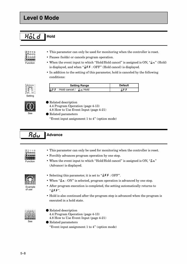
CHAPTER 5 PARAMETERS
E5AK
5--8
Hold
• This parameter can only be used for monitoring when the controller is reset.
• Pauses (holds) or cancels program operation.
• When the event input to which “Hold/Hold cancel” is assigned is ON, “ ” (Hold)is displayed, and when “ : OFF” (Hold cancel) is displayed.
• In addition to the setting of this parameter, hold is canceled by the followingconditions:
Setting Range Default
OFF : Hold cancel / ON: Hold
F Related description4.4 Program Operation (page 4-13)4.8 How to Use Event Input (page 4-21)
F Related parameters“Event input assignment 1 to 4” (option mode)
Advance
• This parameter can only be used for monitoring when the controller is reset.
• Forcibly advances program operation by one step.
• When the event input to which “Hold/Hold cancel” is assigned is ON, “ ”(Advance) is displayed.
• Selecting this parameter, it is set to “ : OFF”.
• When “ : ON” is selected, program operation is advanced by one step.
• After program execution is completed, the setting automatically returns to“ ”.
• Hold is also continued after the program step is advanced when the program isexecuted in a hold state.
F Related description4.4 Program Operation (page 4-13)4.8 How to Use Event Input (page 4-21)
F Related parameters“Event input assignment 1 to 4” (option mode)
Level 0 Mode
Function
Setting
See
Function
Exampleof use
See

E5AK
5--9
Standby time monitor Conditions of UseThe controller must be in a standby state.
• Displays the remaining standby time. (This time is not displayed when the con-troller is reset.)
Monitor Range Unit
0.00 to 99.59 Hour, minute
F Related description4.7 Setting Running Conditions (page 4-19)
F Related parameter“Standby time” (level 2 mode)
Pattern elapsing time
• Displays the time that has elapsed since the start of the pattern. When a pattern isrepeatedly executed or all patterns are executed, the time counting restarts at thetop of each pattern.
Monitor Range Unit
0.00 to 99.59 Program time unit
When the time exceeds “99.59”, “99.59” blinks on the display.
Pattern execution count monitor
• Displays the number of times that the current pattern has been executed. “0” isdisplayed when the controller is reset or when the controller is in a standby state.
Monitor Range Unit
0 to pattern execution count Times
F Related parameter“Pattern execution count” (program mode)
Level 0 Mode
Function
Monitor
See
Function
Monitor
Function
Monitor
See

CHAPTER 5 PARAMETERS
E5AK
5--10
MV monitor (heat)
MV monitor (cool)
Conditions of UseThe control must be standard control orheating and cooling control.
• This parameter cannot be set.• Monitors the manipulated variable on the heating or cooling side.
• The manipulated variable in a standard control system is monitored in the “MVmonitor (heat)” parameter.
• The “MV monitor (cool)” parameter can be used only during heating and coolingcontrol.
• MV monitor (heat)
Control Monitor Range Unit
Standard -5.0 to 105.0 %Heating and cooling 0.0 to 105.0 %
• MV monitor (cool)
Control Monitor Range Unit
Heating and cooling 0.0 to 105.0 %
E5AK-TAA2
Valve opening monitor Conditions of UseThe control must be position-propor-tional control.
• Monitors the valve opening during position-proportional control.
Monitor Range Unit
-10.0 to +110.0 %
“----” is displayed when a potentiometer is not connected.
F Related description4.1 Selecting the Control Method/Position-proportional control (page 4-3)
E5AK-TPRR2
Level 0 Mode
Function
Monitor
Model
Function
Monitor
See
Model
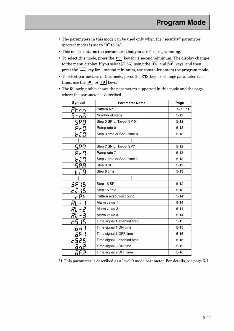
E5AK
5--11
• The parameters in this mode can be used only when the “security” parameter(protect mode) is set to “0” to “4”.
• This mode contains the parameters that you use for programming.
• To select this mode, press the key for 1 second minimum. The display changesto the menu display. If you select [ ] using the and keys, and thenpress the key for 1 second minimum, the controller enters the program mode.
• To select parameters in this mode, press the key. To change parameter set-tings, use the or keys.
• The following table shows the parameters supported in this mode and the pagewhere the parameter is described.
Symbol Parameter Name Page
Pattern No. 5-7 *1
Number of steps 5-12
Step 0 SP or Target SP 0 5-12
Ramp rate 0 5-13
Step 0 time or Soak time 0 5-13
| |
Step 7 SP or Target SP7 5-12
Ramp rate 7 5-13
Step 7 time or Soak time 7 5-13
Step 8 SP 5-12
Step 8 time 5-13
| |
Step 15 SP 5-12
Step 15 time 5-13
Pattern execution count 5-14
Alarm value 1 5-14
Alarm value 2 5-14
Alarm value 3 5-14
Time signal 1 enabled step 5-15
Time signal 1 ON time 5-15
Time signal 1 OFF time 5-16
Time signal 2 enabled step 5-15
Time signal 2 ON time 5-15
Time signal 2 OFF time 5-16
*1 This parameter is described as a level 0 mode parameter. For details, see page 5-7.
Program Mode

CHAPTER 5 PARAMETERS
E5AK
5--12
Number of steps
• Specifies the number of steps in the current pattern.
Setting Range Unit Default1 to 16 None 8
F Related description3.5 Setting Patterns (page 3-14)
F Related parameterAll parameters in the program mode
Step 0 time (Step time)Target SP 0 (Rate of rise programming)
toStep 7 SP (Step time)Target SP 7 (Rate of rise programming)
Step 8 SP (Step time)
Step 15 SP (Step time)
• Sets the SP of steps 0 to 15 when the step time is set.• Sets target SP 0 to 7 when the rate of rise programming is set.
• During temperature input, the decimal point position is dependent on the cur-rently selected sensor, and during analog input on the results of scaling.
Setting Range Unit DefaultSP lower limit to SP upper limit EU 0
F Related description3.5 Setting Patterns (page 3-14)4.3 Ramp Rise Rate Setup Program (page 4-9)
F Related parametersAll parameters in the program mode“Input type” “Scaling upper limit” “Scaling lower limit” “Decimal point” (setupmode)“Step time/Rate of rise programming” (expansion mode)
Program Mode
Function
Setting
See
Conditions of UseWithin the number of steps.
to
Function
Setting
See

E5AK
5--13
Ramp rate 0
to
Ramp rate 7
Conditions of UseWithin the number of steps only in therate of rise programming.
• Sets the degree of change per time unit of ramp rate in the step time ramp step.
Setting Range Unit Default0 to 9999 EU/Time unit of ramp rate 0
0: The ramp step is skipped.
F Related description4.3 Ramp Rise Rate Setup Program (page 4-9)
F Related parametersAll parameters in the program mode“Step time/Rate of rise programming” “Time unit of ramp rate” (expansion mode)
Step 0 time (Step time)Soak time 0 (Rate of rise programming)
toStep 7 time (Step time)Soak time 7 (Rate of rise programming)
Step 8 time (Step time)
Step 15 time (Step time)
• Sets the time of steps 0 to 15 when the step time is set.• Sets soak steps 0 to 7 when the rate of rise programming is set.
Setting Range Unit Default0.00 to 99.59 Program time unit 0.00
F Related description3.5 Setting Patterns (page 3-14)4.3 Ramp Rise Rate Setup Program (page 4-9)
F Related parametersAll parameters in the program mode“Step time/Rate of rise programming” “Program time unit” “Time unit of ramprate” (expansion mode)
Program Mode
Function
Setting
See
Conditions of UseWithin the number of steps.
to
Function
Setting
See

CHAPTER 5 PARAMETERS
E5AK
5--14
Pattern execution count
• Repeatedly executes the current pattern for the preset number of times.• The count during pattern execution can be monitored in the “pattern executioncount monitor” (level 0 mode).
Setting Range Unit Default0 to 9999 Time 1
0: The pattern is not executed
F Related description4.4 Program Operation/Pattern operation (page 4-13)
F Related parametersAll parameters in the program mode
Alarm value 1
Alarm value 2
Alarm value 3
Conditions of UseAlarms must be assigned as outputs.For example, if alarm outputs 1 and 2only are assigned as outputs, the “alarmvalue 3” parameter cannot be used.
• This parameter is used for monitoring or setting the alarm values of alarm out-puts 1 to 3.
• During temperature input, the decimal point position is dependent on the cur-rently selected sensor, and during analog input on the results of scaling.
Setting Range Unit Default-1999 to 9999 EU 0
F Related description3.4Setting Alarm Type (page 3-10)3.5Setting Patterns/Alarm value (page 3-16)
F Related parameters“Input type” “Scaling upper limit” “Scaling lower limit” “Decimal point” “Con-trol output 1 assignment” “Control output 2 assignment” “Auxiliary output 1assignment” “Auxiliary output 2 assignment” “Alarm 1 type” “Alarm 2 type”“Alarm 3 type” “Alarm 1 open in alarm” “Alarm 2 open in alarm” “Alarm 3 openin alarm” (setup mode)“Alarm 1 hysteresis” “Alarm 2 hysteresis” “Alarm 3 hysteresis” (level 2 mode)
Program Mode
Function
Setting
See
Function
Setting
See

E5AK
5--15
Time signal 1 enabledstep
Time signal 2 enabledstep
Conditions of UseEach of the time signals must beassigned as outputs.
• Sets the step in which the time signal is used.
Setting Range Unit Default0 to 15 None 0
F Related description4.6 Program output (page 4-17)
F Related parameters“Time signal 1 ON time” “Time signal 1 OFF time” “Time signal 2 ON time”“Time signal 2 OFF time” (program mode)
Time signal 1 ON time
Time signal 2 ON time
Conditions of UseEach of the time signals must beassigned as outputs.
• Sets the ON time of the time signal.
Setting Range Unit Default0.00 to 99.59 *1 0.00
*1 Program time unit
F Related description4.6 Program Output (page 4-17)
F Related parameters“Time signal 1 enabled step” “Time signal 2 enabled step” “Time signal 1 OFFtime” “Time signal 2 OFF time” (program mode)“Program time unit” (expansion mode)
Program Mode
Function
Setting
See
Function
Setting
See

CHAPTER 5 PARAMETERS
E5AK
5--16
Time signal 1 OFF time
Time signal 2 OFF time
Conditions of UseEach of the time signals must beassigned as outputs.
• Sets the OFF time of the time signal.
Setting Range Unit Default0.00 to 99.59 Program time unit 0.00
F Related description4.6 Program output (page 4-17)
F Related parameters“Time signal 1 enabled step” “Time signal 2 enabled step” “Time signal 1 ONtime” “Time signal 2 ON time” (program mode)“Program time unit” (expansion mode)
Program Mode
Function
Setting
See
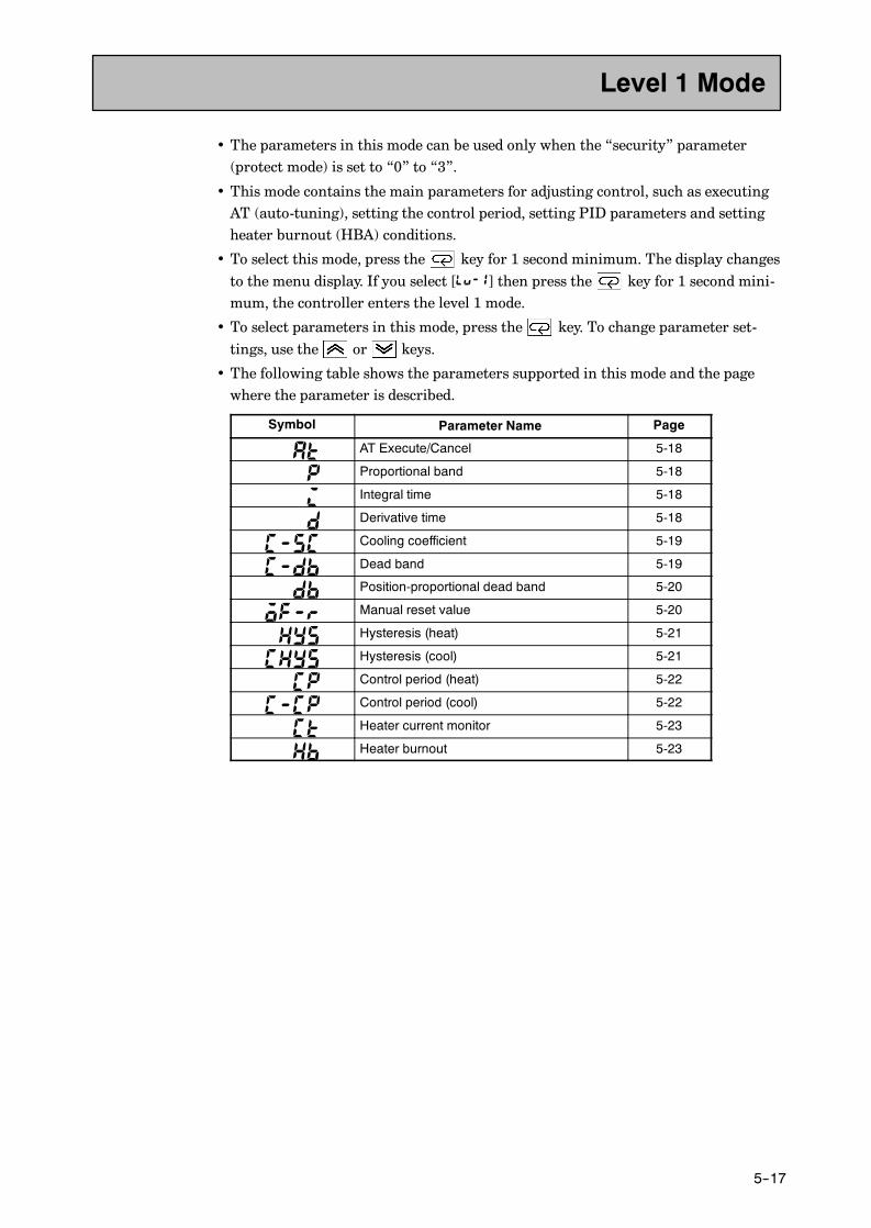
E5AK
5--17
• The parameters in this mode can be used only when the “security” parameter(protect mode) is set to “0” to “3”.
• This mode contains the main parameters for adjusting control, such as executingAT (auto-tuning), setting the control period, setting PID parameters and settingheater burnout (HBA) conditions.
• To select this mode, press the key for 1 second minimum. The display changesto the menu display. If you select [ ] then press the key for 1 second mini-mum, the controller enters the level 1 mode.
• To select parameters in this mode, press the key. To change parameter set-tings, use the or keys.
• The following table shows the parameters supported in this mode and the pagewhere the parameter is described.
Symbol Parameter Name Page
AT Execute/Cancel 5-18
Proportional band 5-18
Integral time 5-18
Derivative time 5-18
Cooling coefficient 5-19
Dead band 5-19
Position-proportional dead band 5-20
Manual reset value 5-20
Hysteresis (heat) 5-21
Hysteresis (cool) 5-21
Control period (heat) 5-22
Control period (cool) 5-22
Heater current monitor 5-23
Heater burnout 5-23
Level 1 Mode

CHAPTER 5 PARAMETERS
E5AK
5--18
AT Execute/Cancel Conditions of UseThe controller must be in operation, andcontrol must be advanced PID control.
• Selects the limit cycle of MV change width (40% or 100%) for execution. After ATexecution, the “PID” and the “LBA detection time” (Loop Break Alarm) parame-ters are automatically set.
• During heating and cooling control or position-proportional control, only 100%ATcan be executed.
• To execute 40%AT, select [ ], and to execute 100%AT, select [ ]. Duringexecution of auto-tuning, the AT LED flashes. However, note that during heatingand cooling control or position-proportional control, [ ] is not displayed.
• When AT execution ends, the parameter setting automatically returns to [ ].
F Related description3.8 Adjusting Control Operation/AT (page 3-25)
F Related parameters“Proportional band” “Integral time” “Derivative time” (level 1 mode)“LBA detection mode” (level 2 mode)
Proportional band
Integral time
Derivative time
Conditions of UseThe control must be advanced PID con-trol.
• Sets the PID parameters. Note that PID is automatically set when AT is executed.
Parameter Setting Range Unit Default
Proportional band 0.1 to 999.9 %FS 10.0Integral time 0 to 3999 *1 Second 233Derivative time 0 to 39999 Second 40
*1: During position-proportional control, the setting range become 1 to 3999seconds.
F Related parameter“AT Execute/Cancel” (level 1 mode)
Level 1 Mode
Function
Exampleof use
See
Function
Setting
See

E5AK
5--19
Cooling coefficient Conditions of UseThe control must be either heating andcooling control, or advanced PID control.
• In heating and cooling control, P at the cooling side is calculated by the followingformula:Cooling side P = Cooling coefficient x P
Setting Range Unit Default0.01 to 99.99 None 1.00
F Related description4.1 Selecting the Control Method/Heating and cooling control (page 4-2)
F Related parameter“Proportional band” (level 1 mode)
E5AK-TAA2
Dead band Conditions of UseThe control system must be heating andcooling control.
• Sets the output dead band width in a heating and cooling control system. A nega-tive setting sets an overlap band.
Setting Range Unit Default-19.99 to 99.99 %FS 0.00
F Related description4.1 Selecting the Control Method/Heating and cooling control (page 4-2)
E5AK-TAA2
Level 1 Mode
Function
Setting
See
Model
Function
Setting
See
Model

CHAPTER 5 PARAMETERS
E5AK
5--20
Position-proportionaldead band
Conditions of UseThe control must be position-propor-tional control.
• Sets the output hold width (ON/OFF switching point for open and close output)during position-proportional control.
Setting Range Unit Default0.1 to 10.0 % 2.0
F Related description4.1 Selecting the Control Method/Position-proportional control (page 4-3)
F Related parameter“Open/close hysteresis” (level 2 mode)
E5AK-TPRR2
Manual reset value Conditions of UseThe control must be either standard con-trol or advanced PID control, and the“integral time” parameter must be set to“0”.
• Sets the required manipulated variable to remove offset during stabilization of Por PD control.
Setting Range Unit Default0.0 to 100.0 % 50.0
E5AK-TAA2
Level 1 Mode
Function
Setting
See
Model
Function
Setting
Model

E5AK
5--21
Hysteresis (heat)
Hysteresis (cool)
Conditions of UseThe control system must be ON/OFFcontrol.
• Sets the hysteresis for ensuring stable operation at ON/OFF switching.
• In a standard control system, use the “hysteresis (heat)” parameter. The “hystere-sis (cool)” parameter cannot be used.
• In a heating and cooling control system, the hysteresis can be set independentlyfor heating and cooling. Use the “hysteresis (heat)” parameter to set the heatingside hysteresis, and use the “hysteresis (cool)” parameter to set the cooling sidehysteresis.
Parameter Setting Range Unit Default
Hysteresis (heat) 0.01 to 99.99 %FS 0.10Hysteresis (cool) 0.01 to 99.99 %FS 0.10
F Related description4.1 Selecting the Control Method/ON/OFF control (page 4-5)
F Related parameters“Control output 1 assignment” “Control output 2 assignment” (setup mode)“PID/ON/OFF” (expansion mode)
E5AK-TAA2
Level 1 Mode
Function
Setting
See
Model
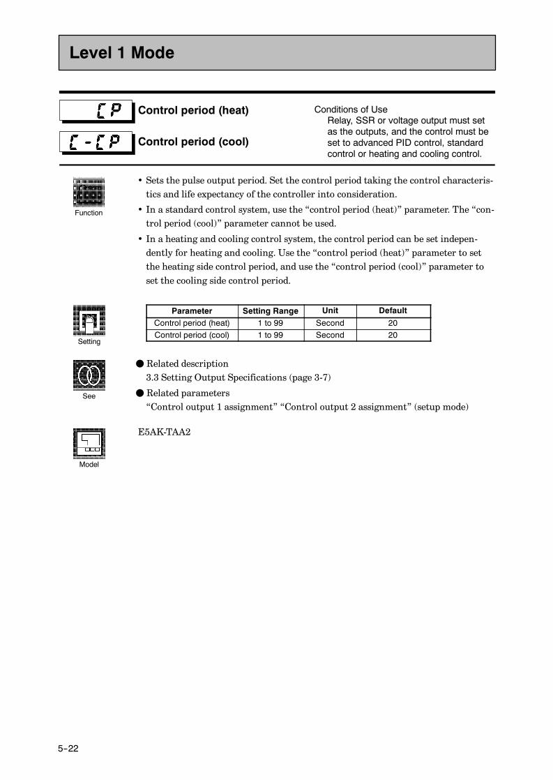
CHAPTER 5 PARAMETERS
E5AK
5--22
Control period (heat)
Control period (cool)
Conditions of UseRelay, SSR or voltage output must setas the outputs, and the control must beset to advanced PID control, standardcontrol or heating and cooling control.
• Sets the pulse output period. Set the control period taking the control characteris-tics and life expectancy of the controller into consideration.
• In a standard control system, use the “control period (heat)” parameter. The “con-trol period (cool)” parameter cannot be used.
• In a heating and cooling control system, the control period can be set indepen-dently for heating and cooling. Use the “control period (heat)” parameter to setthe heating side control period, and use the “control period (cool)” parameter toset the cooling side control period.
Parameter Setting Range Unit Default
Control period (heat) 1 to 99 Second 20Control period (cool) 1 to 99 Second 20
F Related description3.3 Setting Output Specifications (page 3-7)
F Related parameters“Control output 1 assignment” “Control output 2 assignment” (setup mode)
E5AK-TAA2
Level 1 Mode
Function
Setting
See
Model

E5AK
5--23
Heater current monitor Conditions of UseThe HBA output function must beassigned as the output.
• Measures the current value of the heater from CT input.
• This parameter is not displayed when the linear output unit (E53-CV, E53-VV) ismounted.
Monitor Range Unit0.0 to 55.0 A
• [ ] is displayed when 55.0 A is exceeded.
F Related description4.9 How to Use the Heater Burnout Alarm (page 4-23)
F Related parameters“Heater burnout” (level 1 mode)“HBA latch” (option mode)
E5AK-TAA2
Heater burnout Conditions of UseThe HBA output function must beassigned as the output
• Outputs the heater burnout alarm when the heater current value falls below thisparameter setting.
• When the set value is “0.0”, the heater burnout alarm is “OFF”. When the setvalue is “50.0”, the heater burnout alarm is “ON”.
Setting Range Unit Default0.0 to 50.0 A 0.0
F Related description4.9 How to Use the Heater Burnout Alarm (page 4-23)
F Related parameters“Heater current monitor” (level 1 mode)“HBA latch” (option mode)
E5AK-TAA2
Level 1 Mode
Function
Monitor
See
Model
Function
Setting
See
Model

CHAPTER 5 PARAMETERS
E5AK
5--24
• The parameters in this mode can be used only when the “security” parameter(protect mode) is set to “0” to “2”.
• This mode contains the auxiliary parameters for adjusting control. These parame-ters include parameters for limiting the manipulated variable, parameters forswitching between remote and local operation, and parameters for setting theLBA (Loop Break Alarm), alarm hysteresis, and input digital filter values.
• To select this mode, press the key for 1 second minimum. The display changesto the menu display. If you select [ ] pressing the and keys, and thenpress the key for 1 second minimum, the controller enters the level 2 mode.
• To select parameters in this mode, press the key. To change parameter set-tings, use the or keys.
• The following table shows the parameters supported in this mode and the pagewhere the parameter is described.
Symbol Parameter Name Page
Remote/Local 5-25
Standby time 5-25
LBA detection time 5-26
MV at reset 5-26
MV at PV error 5-27
MV upper limit 5-27
MV lower limit 5-27
MV change rate limit 5-27
Input digital filter 5-28
Open/close hysteresis 5-28
Alarm 1 hysteresis 5-29
Alarm 2 hysteresis 5-29
Alarm 3 hysteresis 5-29
Input shift upper limit 5-29
Input shift lower limit 5-29
Level 2 Mode

E5AK
5--25
Remote/Local Conditions of UseThe communications function must be inuse.
• Switches between remote and local operation.• To change the parameter setting during remote operation, use the communica-tions function. To change the parameter setting during local operation, change thesetting on the E5AK-T controller. You can check the parameter setting by bothcommunications and on the E5AK-T controller regardless of whether the control-ler is switched to remote or local operation.
• When the event input to which “remote/local” is assigned is ON, the controllerswitches to the remote mode. When the event input is OFF, the controller switchesto the local mode.
Setting Range Default
“ ”: remote / “ ”: local
F Related descriptionChapter 6 Using the Communications Functions
F Related parameters“Communication stop bit” “Communication data length” “Communication par-ity” “Communication baud rate” “Communication unit No.” “Event input assign-ment 1” “Event input assignment 2” “Event input assignment 3” “Event inputassignment 4” (option mode)
F Option unitsE53-AK01/02/03
Standby time
• Sets the time until program operation is started after the run instruction is issued.
Setting Range Unit Default0.00 to 99.59 Hour, minute 0.00
F Related description4.7 Setting Running Conditions/Starting the program run/Standby operation(page 4-20)
F Related parameter“Standby time monitor” (level 0 mode)
Level 2 Mode
Function
Setting
See
Model
Function
Setting
See

CHAPTER 5 PARAMETERS
E5AK
5--26
LBA detection time Conditions of UseThe LBA (Loop Break Alarm) functionmust be assigned as an output.
• This parameter is automatically set by AT execution.• The LBA is output if the change width of the process value falls below 0.2 %full-scale of the time preset to this parameter when the manipulated variable is set inthe “MV upper limit” or “MV lower limit” parameters.
• The LBA function is disabled when this parameter is set to “0”.
Setting Range Unit Default
0 to 9999 Second 0
F Related description4.10 LBA (page 4-20)8.3 How to Use Error Output (page 8-5)
F Related parameters“AT Execute/Cancel” (level 1 mode)“Control output 1 assignment” “Control output 2 assignment” “Auxiliary output1 assignment” “Auxiliary output 2 assignment” (setup mode)
MV at reset
MV at PV error
Conditions of UseAdvanced PID control.
• The “MV at reset” parameter sets the manipulated variable when operation hasstopped on a standard type controller. On a position-proportional type controller,this parameter sets the action (close/hold/open) when operation has stopped.
• The “MV at PV error” parameter sets the manipulated variable when an inputerror occurs. On a position-proportional type controller, this parameter sets theaction (close/hold/open) when an input error occurs.
• Standard type
Control Method Setting Range Unit Default
Standard -5.0 to 105.0 % 0.0Heating and cooling -105.0 to 105.0 % 0.0
The manipulated variable at the cooling side during heating and cooling control isexpressed as a negative value.
• Position-proportional type
Setting Range Unit Default
“ ”: Hold/“ ”: Open/“ ”: Close None
F Related descriptionMV at reset : 3.7 Starting and Stopping Operation (page 3-21)MV at PV error : 8.2 How to Use the Error Display (page 8-3)
Level 2 Mode
Function
Setting
See
Function
Setting
See

E5AK
5--27
MV upper limit
MV lower limit
MV change rate limit
Conditions of UseThe control must be advanced PID con-trol.
• The “MV upper limit” and “MV lower limit” parameters set the upper and lowerlimits of the manipulated variable. When the manipulated variable calculated bythe E5AK-T controller strays from the upper- and lower-limit range, the upperlimit or lower limit set to these parameters is output, respectively. However, notethat these parameters are disabled during position-proportional control.
• The “MV change rate limit” parameter sets the maximum permissible changewidth per second of the manipulated variable (on the position-proportional con-trol, valve opening). If a change in the manipulated variable (on the position-pro-portional control, valve opening) causes this parameter setting to be exceeded, thecalculated value is reached while changing the value by the per-second value set inthis parameter.This function is disabled when the set value is “0.0”.
• MV upper limitThe setting ranges during standard control and heating and cooling control aredifferent.
Control Method Setting Range Unit Default
Standard MV lower limit +0.1 to 105.0 % 105.0Heating and cooling 0.0 to 105.0 % 105.0
The manipulated variable at the cooling side during heating and cooling control isexpressed as a negative value.
• MV lower limitThe setting ranges during standard control and heating and cooling control are dif-ferent.
Control Method Setting Range Unit Default
Standard -5.0 to MV upper limit -0.1 % -5.0Heating and cooling -105.0 to 0.0 % -105.0
The manipulated variable at the cooling side during heating and cooling control isexpressed as a negative value.
• MV change rate limit
Setting Range Unit Default
0.0 to 100.0 %/S 0.0
F Related description4.2 Operating Condition Restrictions/Manipulated variable restrictions (page 4-7)
Level 2 Mode
Function
Setting
See
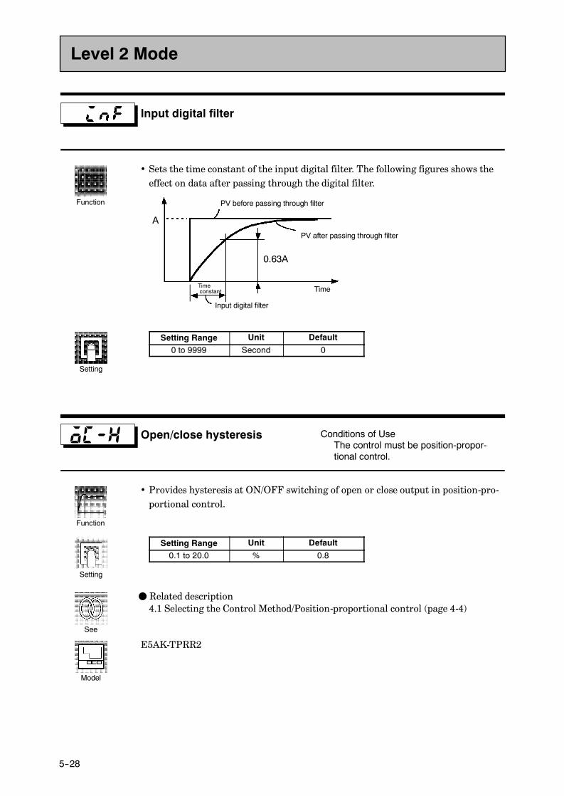
CHAPTER 5 PARAMETERS
E5AK
5--28
Input digital filter
• Sets the time constant of the input digital filter. The following figures shows theeffect on data after passing through the digital filter.
A
PV before passing through filter
PV after passing through filter
0.63A
Input digital filter
Timeconstant Time
Setting Range Unit Default
0 to 9999 Second 0
Open/close hysteresis Conditions of UseThe control must be position-propor-tional control.
• Provides hysteresis at ON/OFF switching of open or close output in position-pro-portional control.
Setting Range Unit Default
0.1 to 20.0 % 0.8
F Related description4.1 Selecting the Control Method/Position-proportional control (page 4-4)
E5AK-TPRR2
Level 2 Mode
Function
Setting
Function
Setting
See
Model
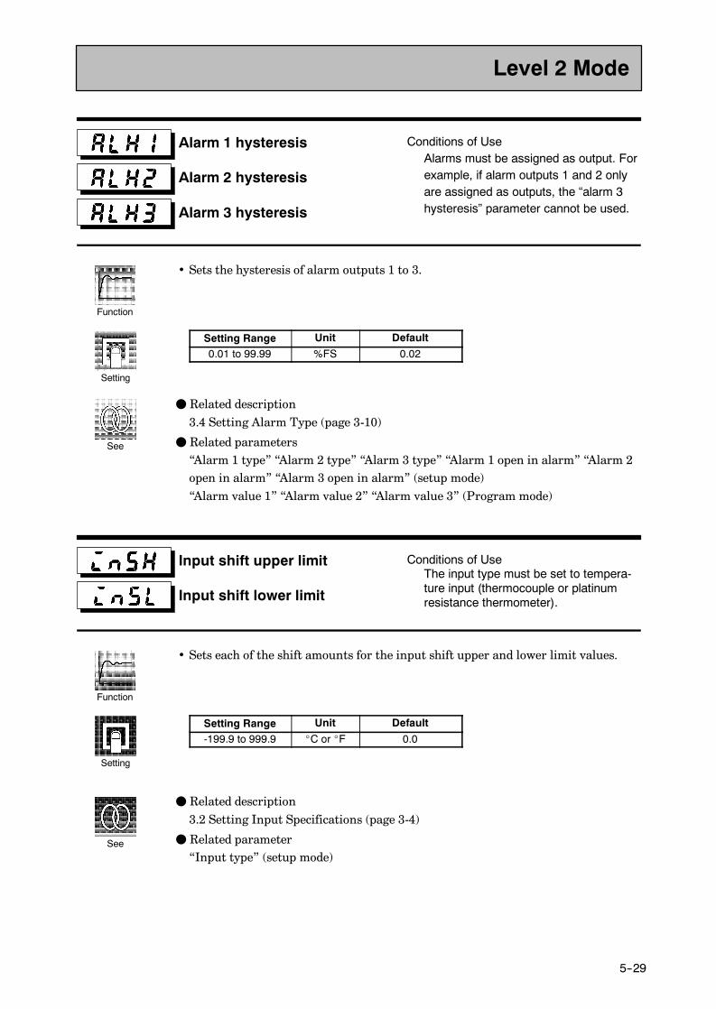
E5AK
5--29
Alarm 1 hysteresis
Alarm 2 hysteresis
Alarm 3 hysteresis
Conditions of UseAlarms must be assigned as output. Forexample, if alarm outputs 1 and 2 onlyare assigned as outputs, the “alarm 3hysteresis” parameter cannot be used.
• Sets the hysteresis of alarm outputs 1 to 3.
Setting Range Unit Default
0.01 to 99.99 %FS 0.02
F Related description3.4 Setting Alarm Type (page 3-10)
F Related parameters“Alarm 1 type” “Alarm 2 type” “Alarm 3 type” “Alarm 1 open in alarm” “Alarm 2open in alarm” “Alarm 3 open in alarm” (setup mode)“Alarm value 1” “Alarm value 2” “Alarm value 3” (Program mode)
Input shift upper limit
Input shift lower limit
Conditions of UseThe input type must be set to tempera-ture input (thermocouple or platinumresistance thermometer).
• Sets each of the shift amounts for the input shift upper and lower limit values.
Setting Range Unit Default
-199.9 to 999.9 _C or _F 0.0
F Related description3.2 Setting Input Specifications (page 3-4)
F Related parameter“Input type” (setup mode)
Level 2 Mode
Function
Setting
See
Function
Setting
See
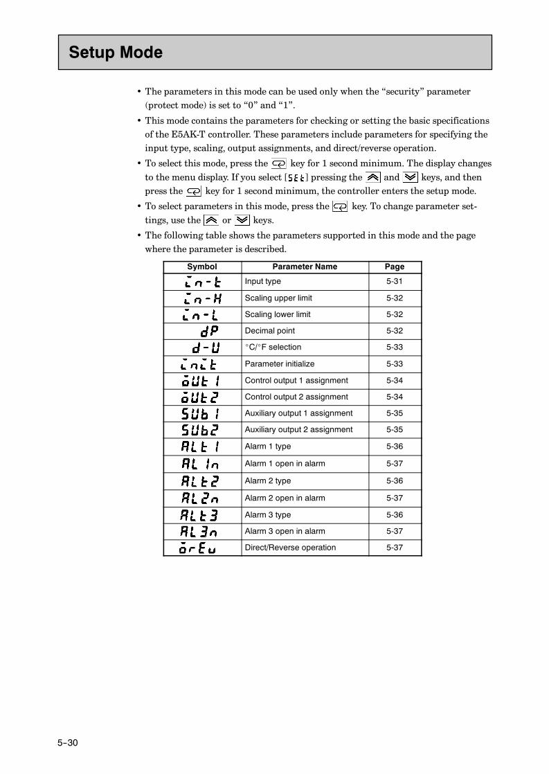
CHAPTER 5 PARAMETERS
E5AK
5--30
• The parameters in this mode can be used only when the “security” parameter(protect mode) is set to “0” and “1”.
• This mode contains the parameters for checking or setting the basic specificationsof the E5AK-T controller. These parameters include parameters for specifying theinput type, scaling, output assignments, and direct/reverse operation.
• To select this mode, press the key for 1 second minimum. The display changesto the menu display. If you select [ ] pressing the and keys, and thenpress the key for 1 second minimum, the controller enters the setup mode.
• To select parameters in this mode, press the key. To change parameter set-tings, use the or keys.
• The following table shows the parameters supported in this mode and the pagewhere the parameter is described.
Symbol Parameter Name Page
Input type 5-31
Scaling upper limit 5-32
Scaling lower limit 5-32
Decimal point 5-32
_C/_F selection 5-33
Parameter initialize 5-33
Control output 1 assignment 5-34
Control output 2 assignment 5-34
Auxiliary output 1 assignment 5-35
Auxiliary output 2 assignment 5-35
Alarm 1 type 5-36
Alarm 1 open in alarm 5-37
Alarm 2 type 5-36
Alarm 2 open in alarm 5-37
Alarm 3 type 5-36
Alarm 3 open in alarm 5-37
Direct/Reverse operation 5-37
Setup Mode

E5AK
5--31
Input type
• Sets the sensor type by the code.
• Set the code according to the following table. Default is “2 : K1 thermocouple”.
Set value Input Type
0 JPt100-199.9 to 650.0 (_C) /-199.9 to 999.9 (_F)Platinum resistance thermometer
1 Pt100 -199.9 to 650.0 (_C) /-199.9 to 999.9 (_F)Platinum resistance thermometer
2 K1 -200 to 1300 (_C) /-300 to 2300 (_F)3 K2 0.0 to 500.0 (_C) /0.0 to 900.0 (_F)4 J1 -100 to 850 (_C) /-100 to 1500 (_F)5 J2 0.0 to 400.0 (_C) /0.0 to 750.0 (_F)6 T -199.9 to 400.0 (_C) /-199.9 to 700.0 (_F)7 E 0 to 600 (_C) /0 to 1100 (_F)8 L1 -100 to 850 (_C) /-100 to 1500 (_F)9 L2 0.0 to 400.0 (_C) /0.0 to 750.0 (_F) Thermocouple10 U -199.9 to 400.0 (_C) /-199.9 to 700.0 (_F)
Thermocouple
11 N -200 to 1300 (_C) /-300 to 2300 (_F)12 R 0 to 1700 (_C) /0 to 3000 (_F)13 S 0 to 1700 (_C) /0 to 3000 (_F)14 B 100 to 1800 (_C) /300 to 3200 (_F)15 W 0 to 2300 (_C) /0 to 4100 (_F)16 PLII 0 to 1300 (_C) /0 to 2300 (_F)17 4 to 20mA
Current input18 0 to 20mA
Current input
19 1 to 5V20 0 to 5V Voltage input21 0 to 10V
Voltage input
F Related description3.2 Setting Input Specifications (page 3-4)
F Related parameterWhen input type is set to temperature input:“_C/_F selection” (setup mode)When input type is set to voltage input or current input:“Scaling upper limit” “Scaling lower limit” “Decimal point” (setup mode)
Setup Mode
Function
Setting
See

CHAPTER 5 PARAMETERS
E5AK
5--32
Scaling upper limit
Scaling lower limit
Decimal point
Conditions of UseThe input type must be set to analoginput (voltage or current input).
• This parameter can be used when voltage input or current input is selected as theinput type.
• When voltage input or current input is selected as the input type, scaling is car-ried out. Set the scaling upper limit in the “scaling upper limit” parameter andthe scaling lower limit in the “scaling lower limit” parameter.
• The “decimal point” parameter specifies the decimal point position of parameters(set point, etc.) whose unit is set to EU (Engineering Unit).
• Scaling upper limit, Scaling lower limit
Parameter Setting Range Unit Default
Scaling upper limit Scaling lower limit +1 to 9999 None 100Scaling lower limit -1999 to scaling upper limit -1 None 0
• Decimal point : Default is “0”.
Set Value Setting Example
0123
0 digits past decimal point1 digit past decimal point2 digits past decimal point3 digits past decimal point
1234123.412.341.234
F Related description3.2 Setting Input Specifications (page 3-4)
F Related parameter“Input type” (setup mode)
Setup Mode
Function
Setting
See

E5AK
5--33
_C/_F selection Conditions of UseThe input type must be set to tempera-ture input (thermocouple or platinumresistance thermometer).
• This parameter can be used when thermocouple or platinum resistance thermom-eter is selected as the input type.
• Set the temperature input unit to either of “_C” or “_F”.
Setting Range Default
“ ”: _C / “ ”: _F
F Related description3.2 Setting Input Specifications (page 3-4)
F Related parameter“Input type” (setup mode)
Parameter initialize
• Returns parameter settings to their factory settings. However, note that the fol-lowing parameters are not affected by execution of this parameter:“Input type”, “Scaling upper limit”, “Scaling lower limit”, “Decimal point” and“_C/_F selection”
• When this parameter is selected, [ ] (“no”) is first displayed. To initialize param-
eters, press the key to specify [ ] (“yes”).
Setup Mode
Function
Setting
See
Function
Exampleof use

CHAPTER 5 PARAMETERS
E5AK
5--34
Control output 1assignment
Control output 2assignment
Conditions of useThe control must be standard control orheating and cooling control.
• Assigns the output functions to either of control output 1 or 2.
• The following 11 output functions can be assigned as outputs:Control output (heat), Control output (cool), Alarms 1 to 3, HBA, LBA, Time sig-nals 1 and 2, Program end and Stage output
• When the output function assigned to control output 1 or control output 2 is ON,the “OUT1” or “OUT2” LED lights. However, note that the “OUT1” or “OUT2”LEDs do not light if the output unit is E53-CVV or E53-VVV when control output(heat) or control output (cool) functions are assigned to control outputs.
Symbol to
Function Control output (heat) Control output (cool) Alarms 1 to 3 HBA LBA
Symbol to
Function Time signals 1 to 2 Program end Stage output
Default :“Control output 1”= [ ], “Control output 2”= [ ].
F Related description3.3 Setting Output Specifications (page 3-7)
F Related parameters
• Alarm-related parameters
• Heating and cooling related parameter“Time signal 1 enabled step” “Time signal 2 enabled step” “Time signal 1 to 2 ONtime” “Time signal 1 to 2 OFF time” (program mode)“LBA detection time” (level 2 mode)
E5AK-TAA2
Setup Mode
Function
Setting
See
Model

E5AK
5--35
Auxiliary output 1 assignment
Auxiliary output 2 assignment
• Assigns output functions to either of auxiliary output 1 or 2.
• The following 11 output functions can be assigned as outputs:Alarms 1 to 3, HBA, LBA, Time signals 1 to 2, Program end, Stage output, Error1 (input error), Error 2 (A/D converter error)
• When the output function assigned to auxiliary output 1 or auxiliary output 2 isON, the SUB1 or SUB2 LED lights.
Symbol to to
Function Alarms 1 to 3 HBA LBA Time signals 1 to 2
Symbol
Function Program end Stage output Error 1 Error 2
Default :“Auxiliary output 1”= [ ], “Auxiliary output 2”= [ ].
F Related description3.3 Setting Output Specifications (page 3-7)
F Related parameters
• Alarm-related parameters“Time signal 1 enabled step” “Time signal 2 enabled step” “Time signal 1 to 2 ONtime” “Time signal 1 to 2 OFF time” (program mode)“LBA detection time” (level 2 mode)
Setup Mode
Function
Setting
See

CHAPTER 5 PARAMETERS
E5AK
5--36
Alarm 1 type
Alarm 2 type
Alarm 3 type
Conditions of UseAlarms must be assigned as outputs.For example, if alarm output 1 and 2only are assigned as outputs, the “alarm3 type” parameter cannot be used.
• “Alarm 1 to 3 type” parameters specify the operation of the alarm by the one ofthe set values in the following table. For details of operation at an alarm, see page3-10.
Set Value Settings Set Value Settings1 Upper- and lower-limit alarm 7 Lower-limit alarm with standby sequence
2 Upper-limit alarm 8 Absolute-value upper-limit alarm
3 Lower-limit alarm 9 Absolute-value lower-limit alarm
4 Upper- and lower-limit rangealarm
10 Absolute-value upper-limit alarm withstandby sequence
5 Upper- and lower-limit alarm withstandby sequence
11 Absolute-value lower-limit alarm withstandby sequence
6 Upper-limit alarm with standbysequence
Default is “2 : upper limit”.
F Related description3.4 Setting Alarm Type (page 3-10)
F Related parameters“Alarm value 1” “Alarm value 2” “Alarm value 3” (Program mode)“Alarm 1 hysteresis” “Alarm 2 hysteresis” “Alarm 3 hysteresis” (level 2 mode)“Alarm 1 open in alarm” “Alarm 2 open in alarm” “Alarm 3 open in alarm” “Con-trol output 1 assignment” “Control output 2 assignment” “Auxiliary output 1assignment” “Auxiliary output 2 assignment” (setup mode)
Setup Mode
Function
Setting
See

E5AK
5--37
Alarm 1 open in alarm
Alarm 2 open in alarm
Alarm 3 open in alarm
Conditions of UseAlarms must be assigned as outputs.For example, if alarm outputs 1 and 2only are assigned as outputs, the “alarm3 open in alarm” parameter cannot beused.
• Sets the output states of alarms 1 to 3.
• When the controller is set to “close in alarm,” the status of the alarm output func-tion is output as it is. When set to “open in alarm,” the status of the alarm outputfunction is output inverted. The following table shows the relationship betweenalarm output functions, alarm output and output LEDs.
Alarm Output Function Alarm Output Output LED
Close in alarmON ON Lit
Close in alarmOFF OFF Not lit
Open in alarmON OFF Lit
Open in alarmOFF ON Not lit
Setting Range Default
“ ” : Close in alarm/ “ ”:Open in alarm
F Related description3.4 Setting Alarm Type (page 3-10)
F Related parameters“Alarm value 1” “Alarm value 2” “Alarm value 3” (level 1 mode)“Alarm 1 hysteresis” “Alarm 2 hysteresis” “Alarm 3 hysteresis” (level 2 mode)“Alarm 1 open in alarm” “Alarm 2 open in alarm” “Alarm 3 open in alarm” “Con-trol output 1 assignment” “Control output 2 assignment” “Auxiliary output 1assignment” “Auxiliary output 2 assignment” (setup mode)
Direct/Reverse operation
• “Direct operation” (or normal operation) refers to control where the manipulatedvariable is increased according to the increase in the process value. Alternatively,“reverse operation” refers to control where the manipulated variable is increasedaccording to the decrease in the process value.
Setting Range Default
“ ” : Reverse operation/ “ ”:Direct operation
F Related description3.3 Setting Output Specifications/Direct/reverse operation (page 3-8)
Setup Mode
Function
Setting
See
Function
Setting
See
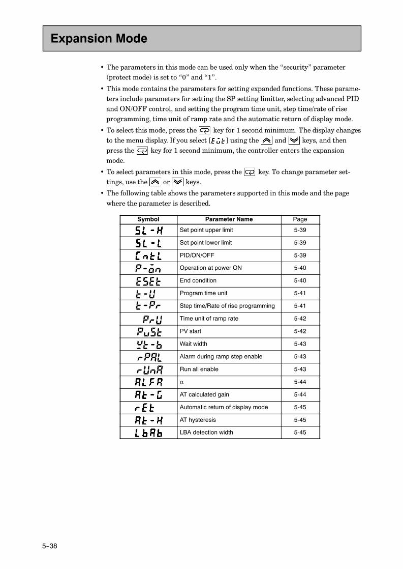
CHAPTER 5 PARAMETERS
E5AK
5--38
• The parameters in this mode can be used only when the “security” parameter(protect mode) is set to “0” and “1”.
• This mode contains the parameters for setting expanded functions. These parame-ters include parameters for setting the SP setting limitter, selecting advanced PIDand ON/OFF control, and setting the program time unit, step time/rate of riseprogramming, time unit of ramp rate and the automatic return of display mode.
• To select this mode, press the key for 1 second minimum. The display changesto the menu display. If you select [ ] using the and keys, and thenpress the key for 1 second minimum, the controller enters the expansionmode.
• To select parameters in this mode, press the key. To change parameter set-tings, use the or keys.
• The following table shows the parameters supported in this mode and the pagewhere the parameter is described.
Symbol Parameter Name Page
Set point upper limit 5-39
Set point lower limit 5-39
PID/ON/OFF 5-39
Operation at power ON 5-40
End condition 5-40
Program time unit 5-41
Step time/Rate of rise programming 5-41
Time unit of ramp rate 5-42
PV start 5-42
Wait width 5-43
Alarm during ramp step enable 5-43
Run all enable 5-43
α 5-44
AT calculated gain 5-44
Automatic return of display mode 5-45
AT hysteresis 5-45
LBA detection width 5-45
Expansion Mode

E5AK
5--39
Set point upper limit
Set point lower limit
• Limits the upper and lower limits when the SP is set. The SP can be set within therange defined by the upper and lower limit set values of the “set point upperlimit” and “set point lower limit ” parameters. Note that as these parameters arereset, the SP of existing settings that are out of the range are forcibly changed toone of the upper or lower limit values.
• When the temperature input type and temperature unit have been changed, theset point upper limit and set point lower limit are forcibly changed to the upperand lower limits of the sensor.
• During temperature input, the decimal point position is dependent on the cur-rently selected sensor, and during analog input on the results of scaling.
Parameter Setting Range Unit Default
Set point upper limit Set point lower limit +1 to scaling upper limit EU 1300Set point lower limit Scaling lower limit to set point upper limit -1 EU -200
During temperature input, the range becomes the range of use of the selected sen-sor instead of the range defined by the scaling upper and lower limit values.
F Related description4.2 Operating Condition Restrictions (page 4-7)
F Related parameter“Input type” “Scaling upper limit” “Scaling lower limit” “Decimal point” (setupmode)
PID/ON/OFF Conditions of UseThe control must be standard control orheating and cooling control.
• Selects advanced PID control or ON/OFF control.
Setting Range Default
“ ” :Advance PID/ “ ” :ON/OFF
F Related description4.1 Selecting the Control Method/ON/OFF control (page 4-5)
F Related parameters“Hysteresis (heat)” “Hysteresis (cool)” (level 1 mode)
E5AK-TAA2
Expansion Mode
Function
Setting
See
Function
Setting
See
Model

CHAPTER 5 PARAMETERS
E5AK
5--40
Operation at power ON
Selects one of the following operations when the power is turned ON:
• “Continue” : Starts operations from the state that was active when the powerwas
interrupted.
• “Reset” : Resets the controller.
• “Run” : Starts normal program operation.
• “Manual” : Sets the controller to the manual mode.
“Manual” cannot be selected when Auto/Manual key operation is protected.
Setting Range Default
“ ” :Continue/ “ ” :Reset/ “ ” Run/ “ ” :Manual
F Related description4.7 Setting Running Conditions/Operation at power ON (page 4-14)
End condition
• Specifies a reset state or continued control on the SP of the final step after pro-gram operation ends.
• The program end state will not change when the “number of steps” parametersetting has been changed after program operation ends. However, when control onthe SP is continued, the SP of the final step is selected after the number of stepshas been changed.
Setting Range Default
“ ” :Reset/ “ ” :Continued control using final SP
F Related description4.7 Setting Running Conditions/End condition (page 4-15)
F Related parameter“Number of steps” (program mode)
Expansion Mode
Function
Setting
See
Function
Setting
See
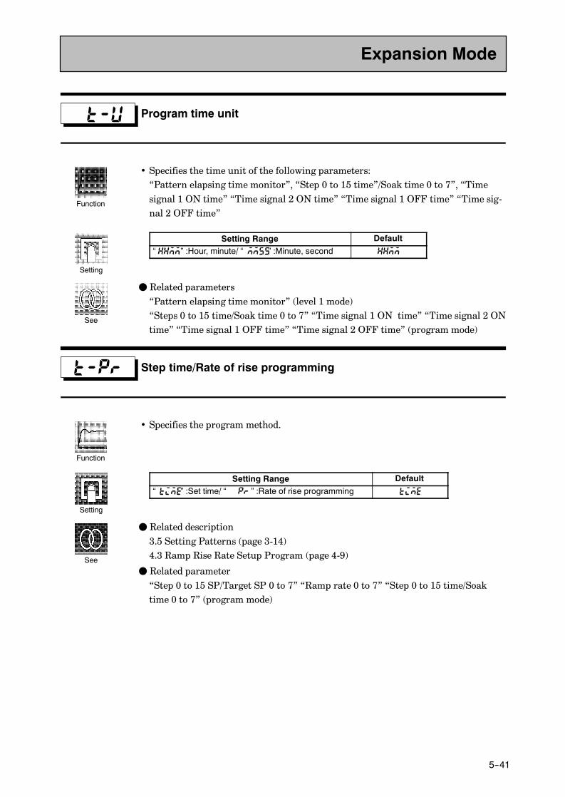
E5AK
5--41
Program time unit
• Specifies the time unit of the following parameters:“Pattern elapsing time monitor”, “Step 0 to 15 time”/Soak time 0 to 7”, “Timesignal 1 ON time” “Time signal 2 ON time” “Time signal 1 OFF time” “Time sig-nal 2 OFF time”
Setting Range Default
“ ” :Hour, minute/ “ ” :Minute, second
F Related parameters“Pattern elapsing time monitor” (level 1 mode)“Steps 0 to 15 time/Soak time 0 to 7” “Time signal 1 ON time” “Time signal 2 ONtime” “Time signal 1 OFF time” “Time signal 2 OFF time” (program mode)
Step time/Rate of rise programming
• Specifies the program method.
Setting Range Default
“ ” :Set time/ “ ” :Rate of rise programming
F Related description3.5 Setting Patterns (page 3-14)4.3 Ramp Rise Rate Setup Program (page 4-9)
F Related parameter“Step 0 to 15 SP/Target SP 0 to 7” “Ramp rate 0 to 7” “Step 0 to 15 time/Soaktime 0 to 7” (program mode)
Expansion Mode
Function
Setting
See
Function
Setting
See

CHAPTER 5 PARAMETERS
E5AK
5--42
Time unit of ramp rate Conditions of UseRate of rise programming must be set.
• Specifies the unit time of “rate of rise 0 to 7.”
Setting Range Default
“ ” : Minute/ “ ” : Hour
F Related parameter“Ramp rate 0 to 7” (program mode)
PV start Conditions of UseThe set time must be set.
Specifies either of the following current SP at the start of program operation:
• PV : Process value at start of program operation (PV start)
• SP : SP of step 0 (normal program operation)
When “PV” is selected, program operation is started from the position where thecurrent SP first matches the PV at the start of program operation. If the SP doesnot match the PV, program operation is started from the beginning of the program.
Setting Range Default
“ ” : PV/ “ ” :SP
F Related description4.7 Setting Running Conditions/Starting the program run/PV start (page 4-20)
Expansion Mode
Function
Setting
See
Function
Setting
See

E5AK
5--43
Wait width
• Specifies the wait width (deviation on SP) during a wait.
• When this parameter is set to “0”, wait is disabled.
Setting Range Unit Default0 to 9999 EU 0
F Related description4.5 Wait Operation (page 4-16)
Alarm during ramp step enable
• To enable alarms during the ramp step, set to [ON]. To disable alarm, set to [OFF].
Setting Range Default
“ ” : / “ ”
Run all enable
• To successively execute the program of all patterns from pattern 0, set to [ON].
• Patterns whose “pattern execution count” parameter (level 1 mode) is set to “0”are skipped.
Setting Range Default
“ ” : / “ ”
Expansion Mode
Function
Setting
See
Function
Setting
Function

CHAPTER 5 PARAMETERS
E5AK
5--44
α Conditions of UseThe control must be advanced PID con-trol.
• Normally, use the default value.
• Sets advanced PID-control parameter α.
Setting Range Unit Default
0.00 to 1.00 None 0.65
AT calculated gain Conditions of UseThe control must be advanced PID con-trol.
• Normally, use the default value.
• Sets the gain when adjusting the PID parameters by auto-tuning.
• To give priority to response, decrease the set value of this parameter. To givepriority to stability, increase the set value of this parameter.
Setting Range Unit Default
0.1 to 10.0 None 1.0
F Related parameter“AT Execute/Cancel” (level 1 mode)“PID/ON/OFF” (expansion mode)
F Related parameter
“PID/ON/OFF” (expansion mode)
Expansion Mode
Function
Setting
Function
Setting
See

E5AK
5--45
Automatic return of display mode
• If you do not operate any of the controller keys for the time set in this parameterwhen in levels 0 to 2 and program modes, the display automatically returns to thePV/Present SP display.
• When this parameter is set to “0”, this function is disabled. (That is, the displaydoes not automatically return to the PV/Present SP display.)
• This parameter is disabled while the menu display is displayed.
Setting Range Unit Default
0 to 99 Second 0
AT hysteresis Conditions of UseThe control must be advanced PID con-trol.
• Normally, use the factory setting.
• The levels of limit cycle operations during AT execution are given hysteresis atevent ON/OFF switching. This parameter sets this hysteresis width.
Setting Range Unit Default
0.1 to 9.9 %FS 0.2
LBA detection width Conditions of UseThe LBA (Loop Break Alarm) functionmust be assigned as an output.
• This parameter can be used when LBA is assigned as an output.
• When the change width of the manipulated variable is below the width set in thisparameter, the controller regards this as detection of an LBA.
Setting Range Unit Default
0.0 to 999.9 %FS 0.2
Expansion Mode
Function
Setting
Function
Setting
Function
Setting

CHAPTER 5 PARAMETERS
E5AK
5--46
• The parameters in this mode can be used only when the “security” parameter(protect mode) is set to “0” and “1”.
• You can select this mode only on controllers that support optional functions. Inthis mode, you can set the communications conditions, transfer output and eventinput parameters to match the type of optional function supported on the control-ler. This mode also contains the parameters for the heater burnout alarm (HBA)function and position-proportional travel time.
• To select this mode, press the key for 1 second minimum. The display changesto the menu display. If you select [ ] using the and keys, and thenpress the key for 1 second minimum, the controller enters the option mode.
• To select parameters in this mode, press the key. To change parameter set-tings, use the or keys.
• The following table shows the parameters supported in this mode and the pagewhere the parameter is described.
Symbol Parameter Name Page
Event input assignment 1 5-47
Event input assignment 2 5-47
Event input assignment 3 5-47
Event input assignment 4 5-47
Communication stop bit 5-48
Communication data length 5-48
Communication parity 5-48
Communication baud rate 5-48
Communication unit No. 5-48
Transfer output type 5-49
Transfer output upper limit 5-49
Transfer output lower limit 5-49
HBA latch 5-50
Motor calibration 5-50
Travel time 5-51
PV dead band 5-51
Option Mode

E5AK
5--47
Event input assignment 1
Event input assignment 2
Event input assignment 3
Event input assignment 4
• When one E53-AKB unit is mounted, only the “event input assignment 3” and“event input assignment 4” parameters can be used.
• The following functions are assigned as event inputs:“Run/Reset,” “Remote/Local,” “Auto/Manual,” “Hold/hold cancel,” “Advance,”“Pattern select 0 to 2”
• The remote/local function can be used on E53-AK01/02/03 option units.
• Weighting of the remote/local function is as follows:Pattern select 0 = 20, Pattern select 1 = 21, Pattern select 2 = 22
• When event input is used as advance input, program steps are advanced at the ris-ing edge of the event input signal. When event input is used as run/reset input, theprogram is reset at the rising edge of the event input signal, and the program runsat the following edge.
Settings Function
Event input disabled
OFF→ON : Reset /ON→OFF : RunON : Remote /OFF : Local
ON : Manual /OFF : Auto
ON : Hold /OFF : Hold cancel
OFF→ON : Execution
Specified by combination of three event inputs (*1)p y p ( )
*1 The following table shows the relationship between the pattern select signaland the pattern No.
Pattern No. 0 1 2 3 4 5 6 7Pattern select 0 Pattern select 1 Pattern select 2
• Default is “ ”.
F Related description4.8 How to Use Event input (page 4-23)
F Related parameters“Remote/local” (level 2 mode)“Hold” “Advance” (level 0 mode)“Pattern No.” (level 0/program mode)
F Option unitsE53-AKB
Option Mode
Function
Setting
See
Model

CHAPTER 5 PARAMETERS
E5AK
5--48
Communication stop bit
Communication data length
Communication parity
Communication baud rate
Communication unit No.
Conditions of UseThe communications function must be inuse.
• These parameters are enabled when the power is turned ON again.
• These parameters set the communications conditions. Make sure that the stop bit,data length, parity and baud rate of the host computer and the E5AK-T controllerare matching.
• When connecting two or more E5AK-T controllers to the host computer, set unitNos. that will not conflict with the unit Nos. of other controllers.
• “Communication stop bit” parameter
Setting Range Unit Default
1, 2 Bits 2
• “Communication data length” parameter
Setting Range Unit Default7, 8 Bits 7
• “Communication parity” parameter
Setting Default
“ ”: None/ “ ”:Even/“ ”:Odd
• “Communication baud rate” parameter
Setting Range Unit Default1.2, 2.4, 4.8, 9.6, 19.2 kbps 9.6
• “Communication unit No.” parameter
Setting Range Unit Default
0 to 99 None 0
F Related descriptionChapter 6 Using the Communications Functions
F Related parameter“Remote/Local” (level 2 mode)
F Option unitsE53-AK01/02/03
Option Mode
Function
Setting
See
Model
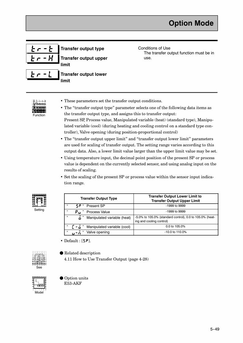
E5AK
5--49
Transfer output type
Transfer output upperlimit
Transfer output lowerlimit
Conditions of UseThe transfer output function must be inuse.
• These parameters set the transfer output conditions.
• The “transfer output type” parameter selects one of the following data items asthe transfer output type, and assigns this to transfer output:Present SP, Process value, Manipulated variable (heat) (standard type), Manipu-lated variable (cool) (during heating and cooling control on a standard type con-troller), Valve opening (during position-proportional control)
• The “transfer output upper limit” and “transfer output lower limit” parametersare used for scaling of transfer output. The setting range varies according to thisoutput data. Also, a lower limit value larger than the upper limit value may be set.
• Using temperature input, the decimal point position of the present SP or processvalue is dependent on the currently selected sensor, and using analog input on theresults of scaling.
• Set the scaling of the present SP or process value within the sensor input indica-tion range.
Transfer Output Type Transfer Output Lower Limit toTransfer Output Upper Limit
“ ” Present SP -1999 to 9999
“ ” Process Value -1999 to 9999
“ ” Manipulated variable (heat) -5.0% to 105.0% (standard control), 0.0 to 105.0% (heat-ing and cooling control)
“ ” Manipulated variable (cool) 0.0 to 105.0%
“ ” Valve opening -10.0 to 110.0%
• Default : [ ].
F Related description4.11 How to Use Transfer Output (page 4-28)
F Option unitsE53-AKF
Option Mode
Function
Setting
See
Model
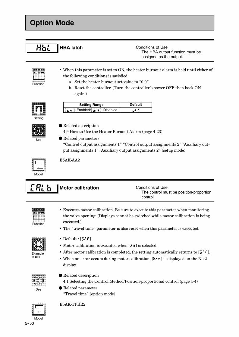
CHAPTER 5 PARAMETERS
E5AK
5--50
HBA latch Conditions of UseThe HBA output function must beassigned as the output.
• When this parameter is set to ON, the heater burnout alarm is held until either ofthe following conditions is satisfied:a Set the heater burnout set value to “0.0”.b Reset the controller. (Turn the controller’s power OFF then back ONagain.)
Setting Range Default
[ ]: Enabled/[ ]: Disabled
F Related description4.9 How to Use the Heater Burnout Alarm (page 4-23)
F Related parameters“Control output assignments 1” “Control output assignments 2” “Auxiliary out-put assignments 1” “Auxiliary output assignments 2” (setup mode)
E5AK-AA2
Motor calibration Conditions of UseThe control must be position-proportioncontrol.
• Executes motor calibration. Be sure to execute this parameter when monitoringthe valve opening. (Displays cannot be switched while motor calibration is beingexecuted.)
• The “travel time” parameter is also reset when this parameter is executed.
• Default : [ ].
• Motor calibration is executed when [ ] is selected.
• After motor calibration is completed, the setting automatically returns to [ ].
• When an error occurs during motor calibration, [ ] is displayed on the No.2
display.
F Related description4.1 Selecting the Control Method/Position-proportional control (page 4-4)
F Related parameter“Travel time” (option mode)
E5AK-TPRR2
Option Mode
Function
Setting
See
Model
Function
Exampleof use
See
Model

E5AK
5--51
Travel time Conditions of UseThe control must be position-proportioncontrol.
• Sets the time from valve fully opened to valve fully closed.
• The travel time is automatically set when the “motor calibration” parameter isexecuted.
Setting Range Unit Default
1 to 999 Second 30
F Related description4.1 Selecting the Control Method/Position-proportional control (page 4-4)
F Related parameters“Motor calibration” (option mode)
E5AK-TPRR2
PV dead band Conditions of UseThe control must be position-proportioncontrol.
• Sets a band centered at SP within which valve will not move.
Set point
Process value
PV dead band
• This function is for special applications, and normally it need not be used. Fordetails, contact your nearest branch of OMRON.
• The decimal is dependent on the results of scaling.
Setting Range Unit Default
0 to 9999 EU 0
F Related parameters“Input type” “Scaling upper limit” “Scaling lower limit” “Decimal point” (setupmode)
E5AK-TPRR2
Option Mode
Function
Setting
See
Model
Function
Setting
See
Model

CHAPTER 5 PARAMETERS
E5AK
5--52
• The parameters in this mode can be used only when the “security” parameter(protect mode) is set to “0”. When selecting this mode for the first time after theE5AK-T has left the factory, return the “security” parameter to “0”.
• This mode contains the parameters for user calibration of inputs and outputs.Only parameters relating to input types specified in the “input type” parameter(setup mode) can be used. Also, related output parameters can be used only whenthe communications unit (E53-AKF) is added on.
• To select this mode, press the key for 1 second minimum. The display changesto the menu display. If you select [ ] using the and keys, and thenpress the key for 1 second minimum, the controller enters the calibrationmode.
• For details on parameters in the calibration mode, see Chapter 7 Calibration.
Calibration Mode
CHAPTER 6 USING THE COMMUNICATIONS FUNCTION
E5AK
6--1
CHAPTER 6USING THECOMMUNICATIONSFUNCTION
This chapter mainly describes communications with a host computerand communications commands.
CHAPTER6
6.1 Outline of the Communications Function 6-2.
Outline 6-2. . . . . . . . . . . . . . . . . . . . . . . . . . . . . . .
Transfer procedure 6-2. . . . . . . . . . . . . . . . . . . . .
Interface 6-2. . . . . . . . . . . . . . . . . . . . . . . . . . . . . .
6.2 Preparing for Communications 6-3. . . . . . . . . .
Cable connections 6-3. . . . . . . . . . . . . . . . . . . . . .
Setting the communications specifications 6-4
6.3 Command Structure 6-5. . . . . . . . . . . . . . . . . . . .
6.4 Commands and Responses 6-7. . . . . . . . . . . . . .
Reading/writing parameters 6-7. . . . . . . . . . . . .
Issuing special commands 6-10. . . . . . . . . . . . . . .
Reading/writing program parameters 6-12. . . .
6.5 How to Read CommunicationsError Information 6-15. . . . . . . . . . . . . . . . . . . . .
End code 6-15. . . . . . . . . . . . . . . . . . . . . . . . . . . . . .
Undefined error 6-16. . . . . . . . . . . . . . . . . . . . . . . .
6.6 Program Example 6-17. . . . . . . . . . . . . . . . . . . . . .
How to use programs 6-17. . . . . . . . . . . . . . . . . . .
Program list 6-18. . . . . . . . . . . . . . . . . . . . . . . . . . .
Examples of use 6-19. . . . . . . . . . . . . . . . . . . . . . . .

CHAPTER 6 USING THE COMMUNICATIONS FUNCTION
E5AK
6--2
6.1 Outline of the Communications Function
The communications function allows you to monitor and set E5AK-Tparameters by a program prepared and running on a host computerconnected to the E5AK-T controller. This chapter describes operationsas viewed from the host computer.
When the communications function is used, the E53-AK01/02/03 com-munications unit must be added on.
The E5AK-T communications function allows you to carry out the fol-lowing:
• Read/write parameters
• Instruct operations
• Select the setting level.
The communications function assumes the following conditions:
• Writing of parameters is possible only during remote operation. Also,parameters cannot be written during execution of auto-tuning.
• Writing of parameters is limited by setting level. Writing conditionsare as follows depending on the setting level:
• Setting level 1: No restrictions
• Setting level 0: Writing of parameters in the setup, expansion andoption modes only is prohibited.
• The “remote/local”, “AT execute/cancel”, “hold/hold cancel” and“advance” parameters are set aside from other parameters as specialcommands for instructing operations.
The host computer sends a “command frame” to the controller, and thecontroller returns a “response frame” corresponding to the content ofthe command sent by the host computer. In other words, a responseframe is returned for each command frame sent.The following diagram shows command frame/response frame opera-tions.
Command frame Command frame
Response frame
Host computerE5AK-T
The host computer carries out communications conforming to theRS-232C, RS-422 or RS-485 interface specifications.Controllers supporting the RS-232C, RS-422 and RS-485 specificationsare as follows:• Option unitsE53-AK01: RS-232CE53-AK02: RS-422E53-AK03: RS-485
JOutline
JTransferprocedure
J Interface

6.2 Preparing for Communications
E5AK
6--3
6.2 Preparing for Communications
For details on wiring when the communications function is used, seeChapter 2 Preparations.
JCable connections• Only one controller can be connected to the host computer.(1:1 connection)
• The cable length should not exceed 15 meters.
• Use shielded twisted-pair cables (AWG28 or more) for the cables.
RS-232C
No.
20 SDRD19
18 SG
E5AK-T
RS-232C
No.
20 SDRD19
18 SG
E5AK--TIBM-PC/XTDE-25FemaleDTE
(SD) TXD
(RD) RXD
(RS) RTS
(CS) CTS
(SG) COMMON
(ER) DTR
(DR) DSR
2
3
4
5
20
6
7
FG 1
(RD) RXD
(SD) TXD
(ER) DTR
(SG) COMMON
(RS) RTS
(CS) CTS
(DR) DSR
2
3
4
5
8
6
7
FG 1
25 pinsIBM-PC/ATDE-25FemaleDTE
9 pins
• 1:1 or 1:N connections are allowed. In a 1:N connection, up to 32 con-trollers including the host computer can be connected.
• The total cable length should not exceed 500 meters.
• Use shielded twisted-pair cables (AWG28 or more) for the cables.
• Attach terminators to the controllers at both ends of the series of con-trollers connected in an open configuration. For example, in the fol-lowing configuration, connect the terminator to unit No.30, and donot connect terminators to unit Nos.0 to 29.
• Use terminators having a resistance of 240 Ω (1/2 W). The total resis-tance of both ends should be at least 100 Ω.
Host computer E5AK-T (No.0) E5AK-T (No.30)
RS-422 RS-422 RS-422
Shielded cableTerminatorX2(240 Ω 1/2 W)
RDA
RDB
SDA
SDB
SG
FG
SDA32
No.
SDB31
RDA19
RDB20
SG18
SDA32
No.
SDB31
RDA19
RDB20
SG18
F RS-232C
F RS-422

CHAPTER 6 USING THE COMMUNICATIONS FUNCTION
E5AK
6--4
• 1:1 or 1:N connections are allowed. In a 1:N connection, up to 32 con-trollers including the host computer can be connected.
• The total cable length should not exceed 500 meters.
• Use shielded twisted-pair cables (AWG28 or more) for the cables.
• Attach terminators to the controllers at both ends of the series of con-trollers connected in an open configuration. For example, in the fol-lowing configuration, connect the terminator to unit No.30, and donot connect terminators to unit Nos.0 to 29.
• Use terminators having a resistance of 120 Ω (1/2 W). The total resis-tance of both ends should be at least 54 Ω.
-
+
FG
RS-485No.
32
31
RS-485No.
32 A
B31
Host computerRS-485
Shielded cable
E5AK-T (No.0) E5AK-T (No.30)
Terminator(120Ω 1/2W)
A
B
A < B : “1” MarkA > B : “0” Space
19
20
A
B
19 A
B20
Match the communications specifications of the host computer andE5AK-T controller. When two or more controllers are connected to thehost computer, make sure that the communications specifications of allcontrollers are the same.This section describes how to set the communications specifications forthe E5AK-T controller. For details on the host computer, see the rele-vant manual supplied with the host computer.
Set the communications specifications of the E5AK-T in the controller’scommunications parameters. The communications parameters are seton the front panel of the E5AK-T controller.The following table shows the communications parameters (optionmode) provided on the E5AK-T controller and their respective settings.
Parameter/Symbol Setting Set ValueUnit No. 0 to 99 0 to 99
Baud rate 1.2/2.4/4.8/9.6/19.2 (kbps) 1.2/2.4/4.8/ 9.6 /19.2
Bit length 7/8 (bit) 7 /8
Parity None/even/odd / e?en /Stop bit 1/2 1/ 2
Inverted items are factory settings.
F RS-485
JSetting the com-municationsspecifications
F Communicationsparameters
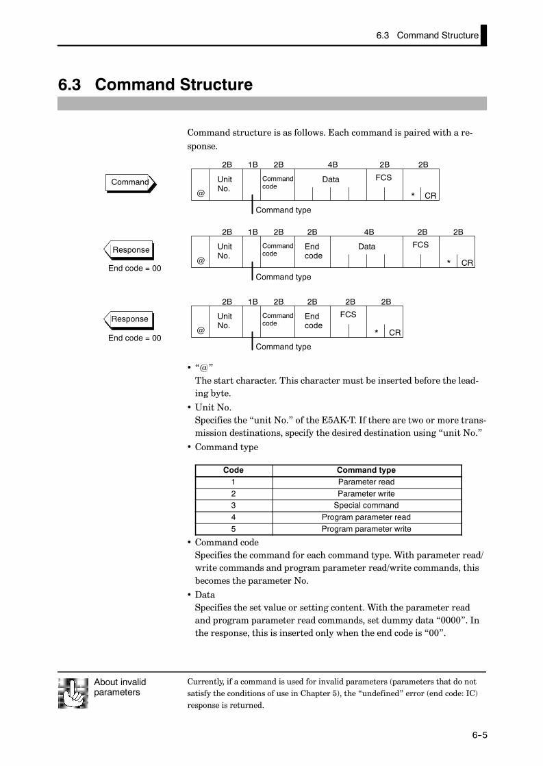
6.3 Command Structure
E5AK
6--5
6.3 Command Structure
Command structure is as follows. Each command is paired with a re-sponse.
UnitNo.
Commandcode
Data FCS
CR
Command type
@ *
2B 1B 2B 4B 2B 2B
Command
UnitNo.
Commandcode
Data FCS
Command type
CR
Endcode@ *
2B 1B 2B 4B 2B 2B2B
Response
End code = 00
UnitNo.
Commandcode
FCS
Command type
CR
Endcode@ *
2B 1B 2B 2B 2B2B
End code = 00
Response
• “@”The start character. This character must be inserted before the lead-ing byte.
• Unit No.Specifies the “unit No.” of the E5AK-T. If there are two or more trans-mission destinations, specify the desired destination using “unit No.”
• Command type
Code Command type1 Parameter read2 Parameter write3 Special command4 Program parameter read5 Program parameter write
• Command codeSpecifies the command for each command type. With parameter read/write commands and program parameter read/write commands, thisbecomes the parameter No.
• DataSpecifies the set value or setting content. With the parameter readand program parameter read commands, set dummy data “0000”. Inthe response, this is inserted only when the end code is “00”.
Currently, if a command is used for invalid parameters (parameters that do notsatisfy the conditions of use in Chapter 5), the “undefined” error (end code: IC)response is returned.
About invalidparameters

CHAPTER 6 USING THE COMMUNICATIONS FUNCTION
E5AK
6--6
• End codeSets the communication results. For details on the types and mean-ings of end codes, see 6.5 How to Read Communications Error In-formation (page 6-12).
• FCS (Frame Check Sequence)Set the frame check results from the start character to the data area.For details on the frame check, see 6.6 Program Example (page 6-18).
• “*” “CR (Carriage Return) code”Indicates the end (terminator) of the command or response block.
F Conversion to ASCII code at each digit of the calculation result and setting to FCS
Calculate the exclusive OR from the start character to the data section. The fol-lowing describes an example of how to calculate the FCS for “@001000000”.
How to CalculateFCS
(1) Convert the ASCII codes of each character to Hexadecimal “40H, 30H, ...,
30H”.
(2) Calculate the exclusive OR of all characters.
(3) Convert to ASCII code. (→ “4B”)
(4) Set the result as FCS.
F ASCII→ Hex
ASCII @ 0 0 1 0 0 0 0 0 0
Hex 40H 30H 30H 31H 30H 30H 30H 30H 30H 30H
F Completed frame (with appended terminator)
F Exclusive OR
ASCII @ 0 0 1 0 0 0 0 0 0 7 1
Hex 40H 30H 30H 31H 30H 30H 30H 30H 30H 30H 37H 31H
ASCII @ 0 0 1 0 0 0 0 0 0 7 1 * CR
Hex 40H 30H 30H 31H 30H 30H 30H 30H 30H 30H 37H 31H 2AH 0DH
FCS
FCS Terminator
40H¨30H¨30H¨31H¨30H¨30H¨30H¨30H¨30H¨30H¨=71H

6.4 Commands and Responses
E5AK
6--7
6.4 Commands and Responses
This section describes commands and response in detail. The conven-tions used in this section and data restrictions are as follows:
• Data is expressed in 1-byte units and in ASCII code.
• When the read or write data is a numerical value, the data to be setmust conform to the following conditions:
(1)The decimal point “.” is not indicated in fractions.(2)The leftmost bit of minus numerical data must be expressed as follows:A: -1, F: - (minus)[example]10.0=[0100], -150.0=[A500], -15=[F015]
JReading/writing parameters
F Reading parameters
Command
ParameterNo.
ParameterNo.
UnitNo.
FCS
CR
UnitNo.
Read data FCS
CR
Endcode
@
@
*
*
2B 2B 4B 2B 2B
2B 2B 4B 2B 2B2B
1 0 0 0 0
1Response
FWriting parameters
Command
ParameterNo.
ParameterNo.
UnitNo.
Write data FCS
CR
UnitNo.
Write data FCS
CR
Endcode
@
@
*
*
2B 2B 4B 2B 2B
2B 2B 4B 2B 2B2B
2
2Response
Parameters of a specified controller are read or written.
• Writing is possible only during remote operation.
• Reading is impossible during execution of auto-tuning.
• The following are set aside as special commands. For details, see page6-10.
• “Remote/local”, AT execute/cancel”, “Hold/Hold cancel” and“Advance”
• For details on parameters in each setting level, see the tables on page6-8 and 6-9.
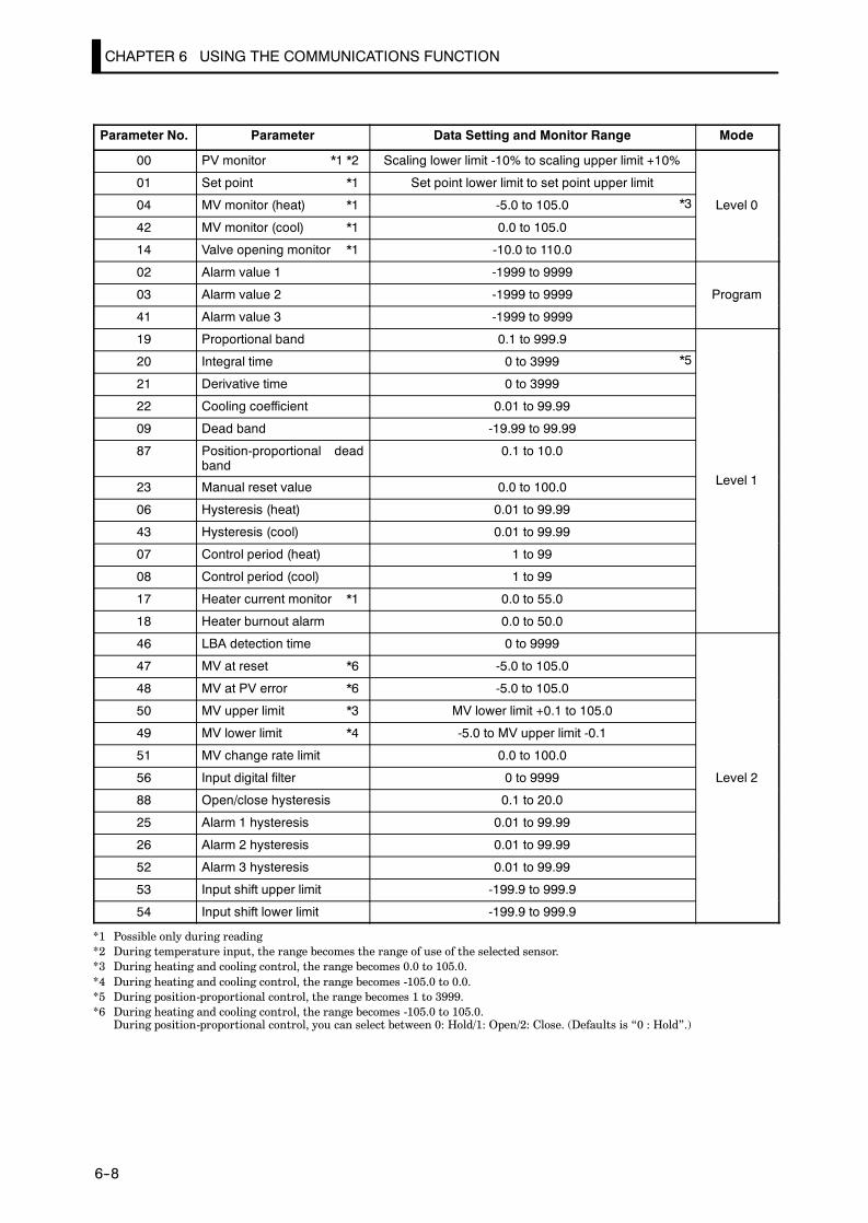
CHAPTER 6 USING THE COMMUNICATIONS FUNCTION
E5AK
6--8
Parameter No. Parameter Data Setting and Monitor Range Mode
00 PV monitor *1 *2 Scaling lower limit -10% to scaling upper limit +10%
01 Set point *1 Set point lower limit to set point upper limit
04 MV monitor (heat) *1 -5.0 to 105.0 Level 0
42 MV monitor (cool) *1 0.0 to 105.0
14 Valve opening monitor *1 -10.0 to 110.0
02 Alarm value 1 -1999 to 9999
03 Alarm value 2 -1999 to 9999 Program
41 Alarm value 3 -1999 to 9999
g
19 Proportional band 0.1 to 999.9
20 Integral time 0 to 3999
21 Derivative time 0 to 3999
22 Cooling coefficient 0.01 to 99.99
09 Dead band -19.99 to 99.99
87 Position-proportional deadband
0.1 to 10.0
L l23 Manual reset value 0.0 to 100.0 Level 1
06 Hysteresis (heat) 0.01 to 99.99
43 Hysteresis (cool) 0.01 to 99.99
07 Control period (heat) 1 to 99
08 Control period (cool) 1 to 99
17 Heater current monitor *1 0.0 to 55.0
18 Heater burnout alarm 0.0 to 50.0
46 LBA detection time 0 to 9999
47 MV at reset *6 -5.0 to 105.0
48 MV at PV error *6 -5.0 to 105.0
50 MV upper limit *3 MV lower limit +0.1 to 105.0
49 MV lower limit *4 -5.0 to MV upper limit -0.1
51 MV change rate limit 0.0 to 100.0
56 Input digital filter 0 to 9999 Level 2
88 Open/close hysteresis 0.1 to 20.0
25 Alarm 1 hysteresis 0.01 to 99.99
26 Alarm 2 hysteresis 0.01 to 99.99
52 Alarm 3 hysteresis 0.01 to 99.99
53 Input shift upper limit -199.9 to 999.9
54 Input shift lower limit -199.9 to 999.9
*1 Possible only during reading*2 During temperature input, the range becomes the range of use of the selected sensor.*3 During heating and cooling control, the range becomes 0.0 to 105.0.*4 During heating and cooling control, the range becomes -105.0 to 0.0.*5 During position-proportional control, the range becomes 1 to 3999.*6 During heating and cooling control, the range becomes -105.0 to 105.0.
During position-proportional control, you can select between 0: Hold/1: Open/2: Close. (Defaults is “0 : Hold”.)
*3
*5
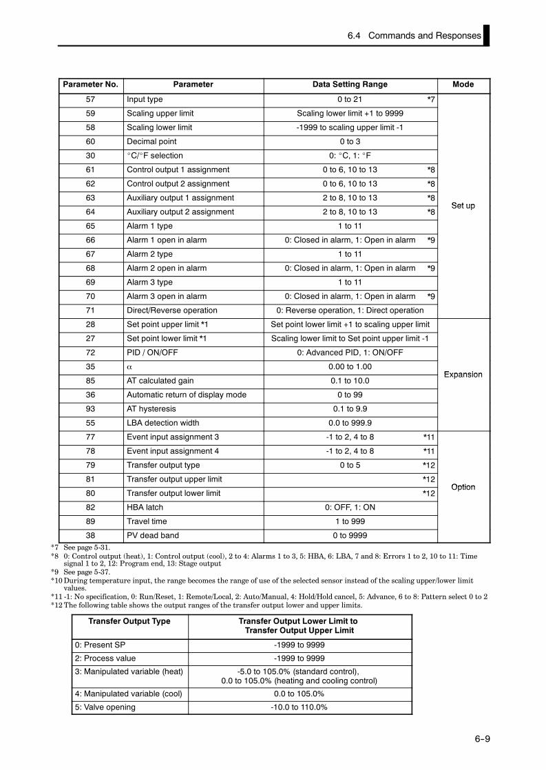
6.4 Commands and Responses
E5AK
6--9
Parameter No. Parameter Data Setting Range Mode
57 Input type 0 to 21
59 Scaling upper limit Scaling lower limit +1 to 9999
58 Scaling lower limit -1999 to scaling upper limit -1
60 Decimal point 0 to 3
30 _C/_F selection 0: _C, 1: _F
61 Control output 1 assignment 0 to 6, 10 to 13
62 Control output 2 assignment 0 to 6, 10 to 13
63 Auxiliary output 1 assignment 2 to 8, 10 to 13Set up
64 Auxiliary output 2 assignment 2 to 8, 10 to 13Set up
65 Alarm 1 type 1 to 11
66 Alarm 1 open in alarm 0: Closed in alarm, 1: Open in alarm
67 Alarm 2 type 1 to 11
68 Alarm 2 open in alarm 0: Closed in alarm, 1: Open in alarm
69 Alarm 3 type 1 to 11
70 Alarm 3 open in alarm 0: Closed in alarm, 1: Open in alarm
71 Direct/Reverse operation 0: Reverse operation, 1: Direct operation
28 Set point upper limit *1 Set point lower limit +1 to scaling upper limit
27 Set point lower limit *1 Scaling lower limit to Set point upper limit -1
72 PID / ON/OFF 0: Advanced PID, 1: ON/OFF
35 α 0.00 to 1.00Expansion
85 AT calculated gain 0.1 to 10.0Expansion
36 Automatic return of display mode 0 to 99
93 AT hysteresis 0.1 to 9.9
55 LBA detection width 0.0 to 999.9
77 Event input assignment 3 -1 to 2, 4 to 8
78 Event input assignment 4 -1 to 2, 4 to 8
79 Transfer output type 0 to 5
81 Transfer output upper limitOption
80 Transfer output lower limitOption
82 HBA latch 0: OFF, 1: ON
89 Travel time 1 to 999
38 PV dead band 0 to 9999*7 See page 5-31.*8 0: Control output (heat), 1: Control output (cool), 2 to 4: Alarms 1 to 3, 5: HBA, 6: LBA, 7 and 8: Errors 1 to 2, 10 to 11: Time
signal 1 to 2, 12: Program end, 13: Stage output*9 See page 5-37.*10During temperature input, the range becomes the range of use of the selected sensor instead of the scaling upper/lower limit
values.*11 -1: No specification, 0: Run/Reset, 1: Remote/Local, 2: Auto/Manual, 4: Hold/Hold cancel, 5: Advance, 6 to 8: Pattern select 0 to 2*12The following table shows the output ranges of the transfer output lower and upper limits.
Transfer Output Type Transfer Output Lower Limit toTransfer Output Upper Limit
0: Present SP -1999 to 9999
2: Process value -1999 to 9999
3: Manipulated variable (heat) -5.0 to 105.0% (standard control),0.0 to 105.0% (heating and cooling control)
4: Manipulated variable (cool) 0.0 to 105.0%
5: Valve opening -10.0 to 110.0%
*7
*8
*8
*8
*8
*9
*9
*9
*11
*11
*12
*12
*12

CHAPTER 6 USING THE COMMUNICATIONS FUNCTION
E5AK
6--10
J Issuing special commands
Commandcode
Commandcode
UnitNo.
Instruction code FCS
CR
UnitNo.
Instruction code FCS
CR
Endcode
@
@
*
*
2B 2B 4B 2B 2B
2B 2B 4B 2B 2B2B
3
3
Command
Response
The following functions are issued as special commands.• Run/ResetRuns or stops programs. This command cannot be issued in settinglevel 1.
• Remote/Local (maximum number of writes: 100,000)Selects remote operation or local operation.
• AT Execute/CancelExecutes or cancels auto-tuning. This command cannot be issued insetting level 1.
• Move to setting level 1Issue this command when writing parameters in the setup, expansionand option modes. On the E5AK-T, the parameter switches to the topparameter “ : input type” of the setup mode, and control isstopped.
• Software resetResets E5AK-T operation (same as turning power ON) by commu-nications. A response is not returned to this command. Also, commu-nications with the E5AK-T cannot be carried out for five seconds afterreset.
• StatusMonitors the status of the E5AK-T. Two command groups are avail-able, A and B, depending on the instruction code. The response is re-turned in bit units to the instruction code (4B) of the response frame.For details on the monitoring details of each group, see page 6-11.
• HoldHolds program execution or cancels hold. This command cannot beissued in setting level 1.
• AdvanceAdvances execution of steps in the program. This command cannot beissued in setting level 1.
00 Run/Reset 0000: Run, 0001: Reset
02 Remote/Local 0000: Local, 0001: Remote
07 AT Execute/Cancel 0000: Cancel, 0001: 40% AT execu-tion, 0002: 100% AT execution
09 Move to setting level 1 0000
11 Software reset 0000
14 Status 0000: A group, 0001: B group
15 Hold 0000: Hold cancel, 0001: Hold
16 Advance 0000
In the case of the “Run/Reset” or “Advance” command, issue commandwhen the response of the previous command was returned and passedfor 0.5 seconds.

6.4 Commands and Responses
E5AK
6--11
F A groupBit Description [1] [0]
0 Heating side output *3 ON OFF *1
1 Cooling side output *4 ON OFF *1
2 Alarm output 1 ON OFF *2
3 Alarm output 2 ON OFF *2
4 Alarm output 3 ON OFF *2
5 LBA output ON OFF *2
6 HBA output ON OFF *2
7 Run/Reset Reset Run
8 Auto/Manual Manual Auto
9 Remote/Local Remote Local
10
11 AT AT execution OFF
12 Hold During hold OFF
13 Wait During wait OFF
14 Event input 3 ON OFF
15 Event input 4 ON OFF
F B groupBit Description [1] [0]
0 Setting level 1 0
1
2 Control output 1 type Linear Pulse
3 Control output 2 type Linear Pulse
4
5 Input error ON OFF
6 A/D converter error ON OFF
7 CT overflow ON OFF
8 CT hold ON OFF *5
9 Potentiometer error ON OFF
10
11 Time signal 1 output ON OFF *2
12 Time signal 2 output ON OFF *2
13 Ramp/soak Ramp Soak
14 Program end ON OFF *6
15 During standby ON OFF
*1 Always “OFF” at linear output*2 Always “OFF” when output is not assigned*3 During position-proportional control, output is Open.*4 During position-proportional control, output is Close.*5 When the ON time during control output is less than 190 ms, the heater current to
which“ 1” is set and the previous current value is held.
*6 “ON” while the No.2 display indicates [ ]. For details on the [ ] indication,see page 4-15.
To return to setting level 0 from setting level 1, issue the “software reset” com-mand. If the parameter write command is issued for the setup, expansion andoption modes in setting level 0, an error occurs, and the end code (0D = Com-mand cannot be executed) is returned.
About Setting Levels

CHAPTER 6 USING THE COMMUNICATIONS FUNCTION
E5AK
6--12
JReading/writing program parameters
F Reading parameters
ParameterNo.
ParameterNo.
UnitNo.
FCS
CR
UnitNo.
Read data FCS
CR
Endcode
@
@
*
*
2B 2B 4B 2B 2B
2B 2B 4B 2B 2B2B
4 0 0 0 0
4
Command
Response
F Writing parameters
ParameterNo.
ParameterNo.
UnitNo.
Write data FCS
CR
UnitNo.
Write data FCS
CR
Endcode
@
@
*
*
2B 2B 4B 2B 2B
2B 2B 4B 2B 2B2B
5
5
Command
Response
Parameters relating to the program of the specified unit are read orwritten.
• Writing is possible only during remote operation.
• Reading is impossible during execution of auto-tuning.
• For details on parameters in each setting level, see the lists for eachsetting level on pages 6-13 to 6-14.

6.4 Commands and Responses
E5AK
6--13
Parameter No. Parameter Data Setting and Monitor Range Mode
00 Pattern No. *2 0 to 7 *2
01 Step No. monitor *1 0 to number of steps -1
63 Standby time monitor *1 0.00 to 99.59Level 0
02 Pattern elapsing time monitor *1 0.00 to 99.59Level 0
03 Pattern execution count monitor *1 0 to 9999
60 Number of steps 1 to 16
05 Step 0 SP/Target SP 0 SP lower limit to SP upper limit
06 Ramp rate 0 0 to 9999
07 Step 0 time/Soak time 0 0.00 to 99.59
08 Step 1 SP/Target SP 1 SP lower limit to SP upper limit
09 Ramp rate 1 0 to 9999
10 Step 1 time/Soak time 1 0.00 to 99.59
11 Step 2 SP/Target SP 2 SP lower limit to SP upper limit
12 Ramp rate 2 0 to 9999
13 Step 2 time/Soak time 2 0.00 to 99.59
14 Step 3 SP/Target SP 3 SP lower limit to SP upper limit
15 Ramp rate 3 0 to 9999
16 Step 3 time/Soak time 3 0.00 to 99.59
17 Step 4 SP/Target SP 4 SP lower limit to SP upper limit
18 Ramp rate 4 0 to 9999
19 Step 4 time/Soak time 4 0.00 to 99.59
20 Step 5 SP/Target SP 5 SP lower limit to SP upper limit
21 Ramp rate 5 0 to 9999
22 Step 5 time/Soak time 5 0.00 to 99.59 Program
23 Step 6 SP/Target SP 6 SP lower limit to SP upper limit
g
24 Ramp rate 6 0 to 9999
25 Step 6 time/Soak time 6 0.00 to 99.59
26 Step 7 SP/Target SP 7 SP lower limit to SP upper limit
27 Ramp rate 7 0 to 9999
28 Step 7 time/Soak time 7 0.00 to 99.59
29 Step 8 SP SP lower limit to SP upper limit
30 Step 8 time 0.00 to 99.59
31 Step 9 SP SP lower limit to SP upper limit
32 Step 9 time 0.00 to 99.59
33 Step 10 SP SP lower limit to SP upper limit
34 Step 10 time 0.00 to 99.59
35 Step 11 SP SP lower limit to SP upper limit
36 Step 11 time 0.00 to 99.59
37 Step 12 SP SP lower limit to SP upper limit
38 Step 12 time 0.00 to 99.59
39 Step 13 SP SP lower limit to SP upper limit
40 Step 13 time 0.00 to 99.59
*1 Reading only is possible.*2 Can be used in either the level 0 or program modes.
Read only during program run

CHAPTER 6 USING THE COMMUNICATIONS FUNCTION
E5AK
6--14
Parameter No. Parameter Data Setting and Monitor Range Mode
41 Step 14 SP SP lower limit to SP upper limit
42 Step 14 time 0.00 to 99.59
43 Step 15 SP SP lower limit to SP upper limit
44 Step 15 time 0.00 to 99.59
04 Pattern execution count 0 to 9999
45 Time signal 1 enabled step 0 to 15 Program
46 Time signal 1 ON time 0.00 to 99.59
g
47 Time signal 1 OFF time 0.00 to 99.59
48 Time signal 2 enabled step 0 to 15
49 Time signal 2 ON time 0.00 to 99.59
50 Time signal 2 OFF time 0.00 to 99.59
62 Standby time 0.00 to 99.59 Level 2
54 Operation at power ON *3
55 End condition 0: Reset, 1: Final step SP
51 Program time unit 0: Hour, minute, 1: Minute, second
56 Step time/Rate of rise programming 0: Step time, 1: Rate of rise programming
57 Time unit of ramp rate 0: Minute, 1: Hour Expansion
58 PV start 0: SP start, 1: PV start
p
59 Wait width 0 to 9999
52 Alarm during ramp step enable 0 : OFF, 1 : ON
53 Run all enable 0 : OFF, 1 : ON
*3 0: Continue, 1: Reset, 2: Run, 3: Manual

6.5 How to Read Communications Error Information
E5AK
6--15
6.5 How to Read Communications Error Information
The result of communications on the E5AK-T can be checked by the end code or undefined error re-sponse in the response frame. Use this end code or undefined error response to remedy errors that mayoccur.
Communications are normal when the end code in the response is “00”.If the end code is not “00”, this indicates that an error that is not anundefined error has occurred. The end code format is as follows anddoes not contain a data area.
CR
UnitNo.
Commandcode
FCS
Command type
Endcode@ *
End code 0D Code name Command cannot be executed
• Writing was carried out during local operation.
• Writing was carried out during execution of auto-tuning.
• An attempt was made to execute 40%AT during heating and coolingcontrol or position-proportional control.
• An attempt was made to switch run/reset in setting level 1.
• An attempt was made to execute AT in setting level 1.
• Issue the parameter read or write commands in conditions other thanabove.
End code 10 Code name Parity error
Parity check error was detected in the received data.
Check the communications conditions. If the communications condi-tions of the host computer and E5AK-T controller match, then a prob-able cause is a problem in the communications circuit of one or both ofthe host computer and E5AK-T controller.
End code 11 Code name Framing error
Stop bit cannot be detected.
Check the communications conditions. If the communications condi-tions of the host computer and E5AK-T controller match, then a prob-able cause is a problem in the communications circuit of one or both ofthe host computer and E5AK-T controller.
Responses are not returned unless the target unit for communications and theunit No. defined in the command match.
About the Unit No.
JEnd code
F Description
F Action
F Description
F Action
F Description
F Action

CHAPTER 6 USING THE COMMUNICATIONS FUNCTION
E5AK
6--16
End code 13 Code name FCS error
The FCS (Frame Check Sequence) do not match.
Check the FCS program.
End code 14 Code name Format error
The received command length does not match the length defined in theframe format.
Check the communications conditions. If the communications condi-tions of the host computer and E5AK-T controller match, then a prob-able cause is a problem in the communications circuit of one or both ofthe host computer and E5AK-T controller.
End code 15 Code name Setting range error
Numerical values or code values in the data are not within the settingrange.
Check the parameter and read or write data of special commands.
JUndefined error
CR
UnitNo.
FCS
@ *
2B2B 2B 2B
CI
• An undefined header code has been received.
• A currently invalid parameter (e.g. the scaling command during tem-perature input) has been received.
• Check the parameter No.
F Description
F Action
F Description
F Action
F Description
F Action
F Description
F Action

6.6 Program Example
E5AK
6--17
6.6 Program Example
JHow to use programsThe program described below obtains corresponding response frame data whensome of the command frame data is input.The input format is as follows. The FCS and terminator are automatically gener-ated, and need not be input.
CR
UnitNo.
Commandcode
Data FCS
Command type
@ *
2B2B 1B 2B 4B 2B
Input these data. These are automaticallygenerated.
The output format is as follows. The content of the response frame is displayed as itis.
UnitNo.
Commandcode
Data FCS
Command type
CR
Endcode@ *
2B 1B 2B 4B 2B 2B2B
F Procedure(1) Read the program.
(2) Enter “RUN”.
(3) When “send data:” is displayed, enter the command data (from @ to the com-mand string).
(4) The content of the response frame is displayed following “receive data:”.
F Conditions when running a program• Set the communications conditions as follows:
Baud rate : 9600 bpsBit length : 7 bitsParity : EvenStop bit : 2
• Make sure that the communications cable is properly connected.
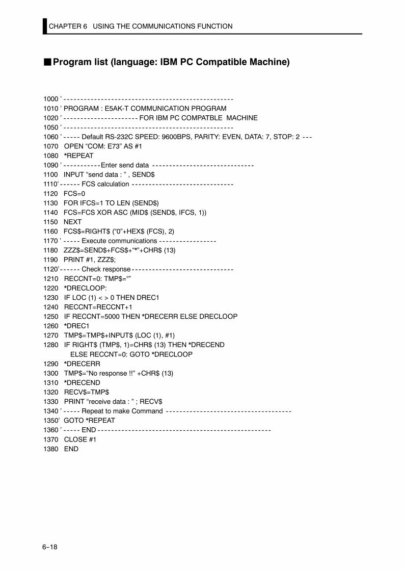
CHAPTER 6 USING THE COMMUNICATIONS FUNCTION
E5AK
6--18
JProgram list (language: IBM PC Compatible Machine)
1000 ’1010 ’ PROGRAM : E5AK-T COMMUNICATION PROGRAM1020 ’ FOR IBM PC COMPATBLE MACHINE1050 ’1060 ’ Default RS-232C SPEED: 9600BPS, PARITY: EVEN, DATA: 7, STOP: 21070 OPEN “COM: E73” AS #11080 *REPEAT1090 ’ Enter send data1100 INPUT “send data : ” , SEND$1110’ FCS calculation1120 FCS=01130 FOR IFCS=1 TO LEN (SEND$)1140 FCS=FCS XOR ASC (MID$ (SEND$, IFCS, 1))1150 NEXT1160 FCS$=RIGHT$ (“0”+HEX$ (FCS), 2)1170 ’ Execute communications1180 ZZZ$=SEND$+FCS$+“*”+CHR$ (13)1190 PRINT #1, ZZZ$;1120’ Check response1210 RECCNT=0: TMP$=“”1220 *DRECLOOP:1230 IF LOC (1) < > 0 THEN DREC11240 RECCNT=RECCNT+11250 IF RECCNT=5000 THEN *DRECERR ELSE DRECLOOP1260 *DREC11270 TMP$=TMP$+INPUT$ (LOC (1), #1)1280 IF RIGHT$ (TMP$, 1)=CHR$ (13) THEN *DRECEND
ELSE RECCNT=0: GOTO *DRECLOOP1290 *DRECERR1300 TMP$=“No response !!” +CHR$ (13)1310 *DRECEND1320 RECV$=TMP$1330 PRINT “receive data : ” ; RECV$1340 ’ Repeat to make Command1350’ GOTO *REPEAT1360 ’ END1370 CLOSE #11380 END

6.6 Program Example
E5AK
6--19
JExamples of use• Set the unit No. to “00”.
• In the following examples, data is shown in individual blocks to make the exam-ples easier to understand. However, when actually creating programs, do not leavespaces between frame items. Also, response are displayed without spaces betweenframe items.
F Set the set point to “300.0”• Input data
@ 00 5 05 3000
300.0
Set point
Write parameter
• Response
@ 00 5 05 00 3000 (FCS) *
Normal end
F Start running• Input data
@ 00 3 00 0000
Run
Run/Reset
Special command
• Response
@ 00 3 00 00 0000 (FCS) *
Normal end
F Monitor process value• Input data
@ 00 1 00 0000
Dummy data
Monitor process value
Read parameter
• Response
@ 00 1 00 00 2000 (FCS) *
Process value = 2000
Normal end

CHAPTER 6 USING THE COMMUNICATIONS FUNCTION
E5AK
6--20

CHAPTER 7 CALIBRATION
E5AK
7--1
CHAPTER 7CALIBRATION
This chapter describes procedures for each calibration operation.Read this chapter only when the controller must be calibrated.
CHAPTER7
7.1 Parameter Structure 7-2. . . . . . . . . . . . . . . . . . .
7.2 Calibrating Thermocouples 7-4. . . . . . . . . . . . .
7.3 Calibrating PlatinumResistance Thermometers 7-7. . . . . . . . . . . . . . .
7.4 Calibrating Current Input 7-9. . . . . . . . . . . . . .
7.5 Calibrating Voltage Input 7-10. . . . . . . . . . . . . . .
7.6 Checking Indication Accuracy 7-12. . . . . . . . . . .

CHAPTER 7 CALIBRATION
E5AK
7--2
7.1 Parameter Structure
• To calibrate the E5AK-T controller, select [ ] in the menu dis-play to select the calibration mode. [ ] .is displayed.
• However, note that [ ] may not be displayed on the menu displaywhen, for example, the user is calibrating the E5AK-T controller forthe first time. If this happens, [ ] is displayed by changing the “se-curity” parameter (protect mode) to “0”.
• The parameters in the calibration mode are structure as follows:
0 to 10V0 to 5V 1 to 5V
Thermocouple
Thermocouple 1
Transfer output
Data storage
Platinum resistancethermometer Voltage inputCurrent input
Thermocouple 2
Thermocouple 1 : K1/J1/L1/E/N/W/PLIIThermocouple 2 : K2/J2/L2/R/S/B/T/UPlatinum resistancethermocouple :JPt100/Pt100
Only when thetransfer outputfunction is sup-ported
• To select the desired parameter, press the key. Parameters aredisplayed in the following order:Calibration of inputs→ Calibration of transfer output→Storage of calibration data
If the E5AK-T controller does not support the transfer output func-tion, calibration of transfer output is automatically deleted from thecalibration procedure as follows:Calibration of inputs→ Storage of calibration data
• Only inputs that have been set in the “input type” parameter (setupmode) can be calibrated. To temporarily store data for each of the cal-ibration parameters, press the key for 1 second.
• Transfer output can be calibrated only when the Communicationsunit (E53-AKF) is set in the controller. To adjust data items, press the
or keys.
• The data store menu is displayed only when all calibration items havetemporarily been stored.
• After calibrating input, you must always check indication accuracy.For details, see page 7-12.
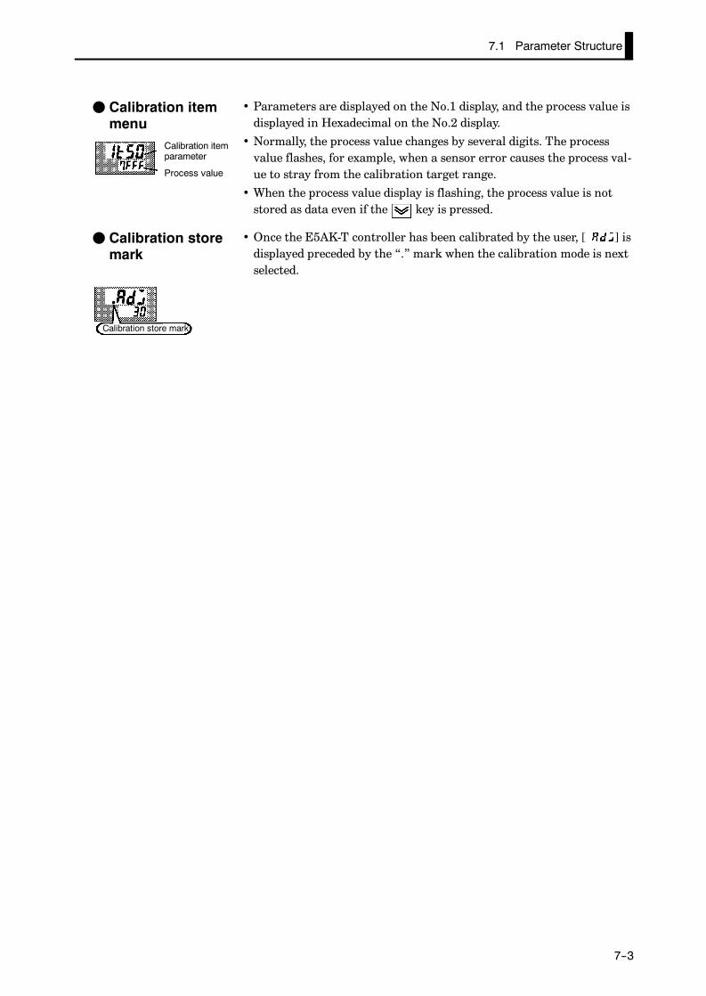
7.1 Parameter Structure
E5AK
7--3
• Parameters are displayed on the No.1 display, and the process value isdisplayed in Hexadecimal on the No.2 display.
• Normally, the process value changes by several digits. The processvalue flashes, for example, when a sensor error causes the process val-ue to stray from the calibration target range.
• When the process value display is flashing, the process value is notstored as data even if the key is pressed.
• Once the E5AK-T controller has been calibrated by the user, [ ] isdisplayed preceded by the “.” mark when the calibration mode is nextselected.
F Calibration itemmenu
Calibration itemparameter
Process value
F Calibration storemark
Calibration store mark

CHAPTER 7 CALIBRATION
E5AK
7--4
7.2 Calibrating Thermocouples
• Calibrate according to the type of thermocouple, thermocouple 1group (K1, J1, L1, E, N, W, PLII) and thermocouple 2 group (K2, K2,L2, R, S, B, T, U).
• When calibrating, do not cover the bottom of the controller. Also, donot touch the input terminals (Nos.11 and 12) or compensating con-ductor on the E5AK-T controller.
F Preparations
10
98
7
6
5
4
3
2
1
30
2928
27
26
25
24
23
22
21
20
1918
17
16
15
14
13
12
11
31 32
33
DMM
STV
Cold junctioncompensator
0_C/32_F
Compensatingconductor
SOURCE
100-240VAC(24VAC/DC)
• Set the cold junction compensator designed for compensation of inter-nal thermocouples to 0_C. However, make sure that internal thermo-couples are disabled (tips are open).
• In the above figure, STV refers to a standard DC current/voltagesource, and DMM refers to a precision digital multimeter.However, note that DMM is required only when the transfer outputfunction is supported.
• Use the compensating conductor on the selected thermocouple. How-ever, note that when thermocouple R, S, E, B, W and PLII is used, thecold junction compensator and the compensating conductor can besubstituted with the cold junction compensator and the compensatingconductor for thermocouple K.
Correct process values cannot be obtained if you touch the contact ends of thecompensating conductor during calibration of a thermocouple. Accordingly, short(enable) or open (disable) the tip of the thermocouple inside the cold junctioncompensator as shown in the figure below to create a contact or non-contact statefor the cold junction compensator.
Connecting theCold JunctionCompensator
0°C/32°F 0°C/32°F
Cold junctioncompensator
Cold junctioncompensator
E5AK E5AK
Compensating conductor Compensating conductor
Short
Open
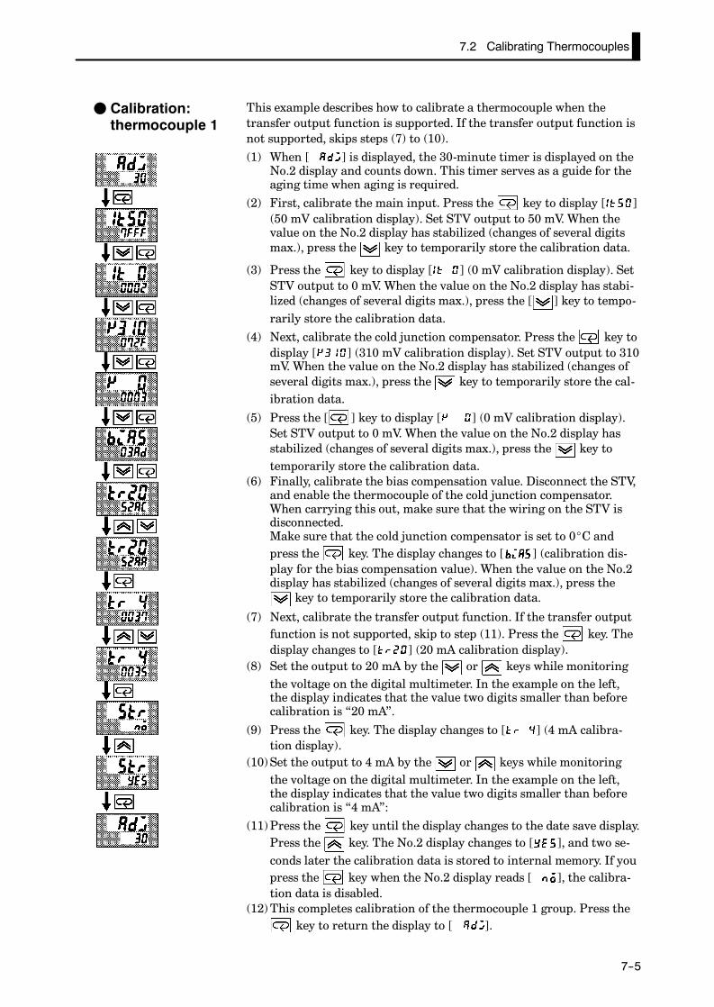
7.2 Calibrating Thermocouples
E5AK
7--5
This example describes how to calibrate a thermocouple when thetransfer output function is supported. If the transfer output function isnot supported, skips steps (7) to (10).
(1) When [ ] is displayed, the 30-minute timer is displayed on theNo.2 display and counts down. This timer serves as a guide for theaging time when aging is required.
(2) First, calibrate the main input. Press the key to display [ ](50 mV calibration display). Set STV output to 50 mV. When thevalue on the No.2 display has stabilized (changes of several digitsmax.), press the key to temporarily store the calibration data.
(3) Press the key to display [ ] (0 mV calibration display). SetSTV output to 0 mV. When the value on the No.2 display has stabi-lized (changes of several digits max.), press the [ ] key to tempo-rarily store the calibration data.
(4) Next, calibrate the cold junction compensator. Press the key todisplay [ ] (310 mV calibration display). Set STV output to 310mV. When the value on the No.2 display has stabilized (changes ofseveral digits max.), press the key to temporarily store the cal-ibration data.
(5) Press the [ ] key to display [ ] (0 mV calibration display).Set STV output to 0 mV. When the value on the No.2 display hasstabilized (changes of several digits max.), press the key totemporarily store the calibration data.
(6) Finally, calibrate the bias compensation value. Disconnect the STV,and enable the thermocouple of the cold junction compensator.When carrying this out, make sure that the wiring on the STV isdisconnected.Make sure that the cold junction compensator is set to 0_C andpress the key. The display changes to [ ] (calibration dis-play for the bias compensation value). When the value on the No.2display has stabilized (changes of several digits max.), press the
key to temporarily store the calibration data.
(7) Next, calibrate the transfer output function. If the transfer outputfunction is not supported, skip to step (11). Press the key. Thedisplay changes to [ ] (20 mA calibration display).
(8) Set the output to 20 mA by the or keys while monitoringthe voltage on the digital multimeter. In the example on the left,the display indicates that the value two digits smaller than beforecalibration is “20 mA”.
(9) Press the key. The display changes to [ ] (4 mA calibra-tion display).
(10)Set the output to 4 mA by the or keys while monitoringthe voltage on the digital multimeter. In the example on the left,the display indicates that the value two digits smaller than beforecalibration is “4 mA”:
(11)Press the key until the display changes to the date save display.Press the key. The No.2 display changes to [ ], and two se-conds later the calibration data is stored to internal memory. If youpress the key when the No.2 display reads [ ], the calibra-tion data is disabled.
(12)This completes calibration of the thermocouple 1 group. Press thekey to return the display to [ ].
F Calibration:thermocouple 1

CHAPTER 7 CALIBRATION
E5AK
7--6
This example describes how to calibrate a thermocouple when thetransfer output function is supported. If the transfer output function isnot supported, skips steps (7) to (10).
(1) When [ ] is displayed, the 30-minute timer is displayed on theNo.2 display and counts down. This timer serves as a guide for theaging time when aging is required.
(2) First, calibrate the main input. Press the key to display[ ] (20 mV calibration display). Set STV output to 20 mV.When the value on the No.2 display has stabilized (changes of sev-eral digits max.), press the key to temporarily store the calibra-tion data.
(3) Press the key to display [ ] (0 mV calibration display). SetSTV output to 0 mV. When the value on the No.2 display has stabi-lized (changes of several digits max.), press the key to tempo-rarily store the calibration data.
(4) Next, calibrate the cold junction compensator. Press the key todisplay [ ] (310 mV calibration display). Set STV output to 310mV. When the value on the No.2 display has stabilized (changes ofseveral digits max.), press the key to temporarily store the cal-ibration data.
(5) Press the key to display [ ] (0 mV calibration display). SetSTV output to 0 mV. When the value on the No.2 display has stabi-lized (changes of several digits max.), press the key to tempo-rarily store the calibration data.
(6) Finally, calibrate the bias compensation value. Disconnect the STV,and enable the thermocouple of the cold junction compensator.When carrying this out, make sure that the wiring on the STV isdisconnected.Make sure that the cold junction compensator is set to 0_C andpress the key. The display changes to [ ] (calibration dis-play for the bias compensation value). When the value on the No.2display has stabilized (changes of several digits max.), press the
key to temporarily store the calibration data.
(7) Next, calibrate the transfer output function. If the transfer outputfunction is not supported, skip to step (11). Press the key. Thedisplay changes to [ ] (20 mA calibration display).
(8) Set the output to 20 mA by the or keys while monitoringthe voltage on the digital multimeter. In the example on the left,the display indicates that the value two digits smaller than beforecalibration is “20 mA”.
(9) Press the key. The display changes to [ ] (4 mA calibra-tion display).
(10)Set the output to 4 mA by the or keys while monitoringthe voltage on the digital multimeter. In the example on the left,the display indicates that the value two digits smaller than beforecalibration is “4 mA”.
(11)Press the key until the display changes to the data store dis-play. Press the key. The No.2 display changes to [ ], and twoseconds later the calibration data is stored to internal memory. Ifyou press the key when the No.2 display reads [ ], the cal-ibration data is disabled.
(12)This completes calibration of the thermocouple 2 group. Press thekey to return the display to [ ].
F Calibration: ther-mocouple 2

7.3 Calibrating Platinum Resistance Thermometers
E5AK
7--7
7.3 Calibrating Platinum Resistance Thermometers
F Preparation
10
9
8
7
6
54
3
2
1
30
29
28
27
26
2524
23
22
21
20
19
18
17
16
1514
13
12
11
31 32
33
DMM
6-dial
SOURCE
100-240VAC(24VAC/DC)
• Use leads of the same thickness when connecting to the platinumresistance thermometer.
• In the above figure, 6-dial refers to a precision resistance box, andDMM stands for a digital multimeter. However, note that the DMM isrequired only when the transfer output function is supported.
• Connect (short) the leads from terminal Nos.11 and 12.
This example describes how to calibrate a platinum resistance ther-mometer when the transfer output function is supported. If the transferoutput function is not supported, skips steps (7) to (10).(1) When [ ] is displayed, the 30-minute timer is displayed on the
No.2 display and counts down. This timer serves as a guide for theaging time when aging is required.
(2) First, calibrate the main input. Press the key to display[ ] (300Ω calibration display). Set the 6-dial to 300Ω. when thevalue on the No.2 display has stabilized (changes of several digitsmax.), press the key to temporarily store the calibration data.
(3) Press the key to display [ ] (0Ω calibration display). Shortterminal No.11 to 13. When the value on the No.2 display has stabi-lized (changes of several digits max.), press the key to tempo-rarily store the calibration data.
(4) Next, calibrate the B-B’ input. Change the wiring as follows:15
14
13
1211
6-dial
Make the connection across terminal Nos.11 and 12 and the 6-dialas short as possible. Short terminal Nos.11 and 13.
F Calibration
Cont’d on next page
Change wiring.
Short terminalNos.11 to 13
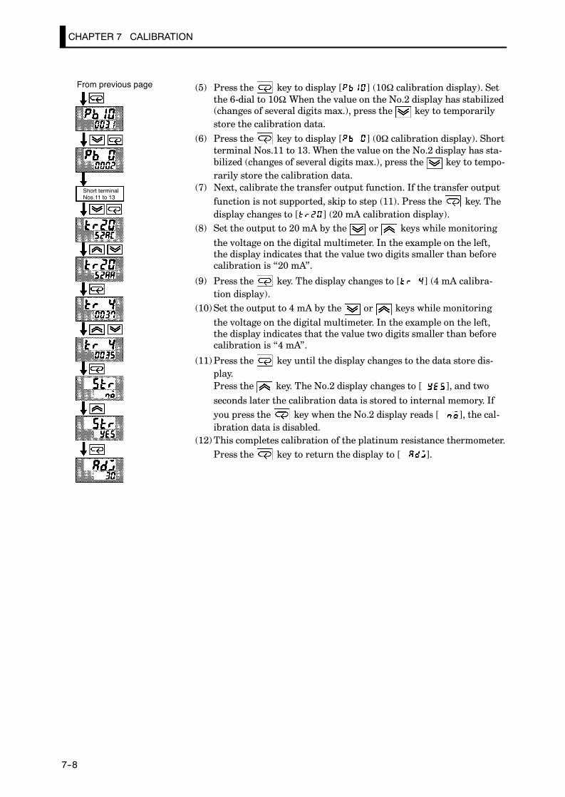
CHAPTER 7 CALIBRATION
E5AK
7--8
(5) Press the key to display [ ] (10Ω calibration display). Setthe 6-dial to 10Ω. When the value on the No.2 display has stabilized(changes of several digits max.), press the key to temporarilystore the calibration data.
(6) Press the key to display [ ] (0Ω calibration display). Shortterminal Nos.11 to 13. When the value on the No.2 display has sta-bilized (changes of several digits max.), press the key to tempo-rarily store the calibration data.
(7) Next, calibrate the transfer output function. If the transfer outputfunction is not supported, skip to step (11). Press the key. Thedisplay changes to [ ] (20 mA calibration display).
(8) Set the output to 20 mA by the or keys while monitoring
the voltage on the digital multimeter. In the example on the left,the display indicates that the value two digits smaller than beforecalibration is “20 mA”.
(9) Press the key. The display changes to [ ] (4 mA calibra-tion display).
(10)Set the output to 4 mA by the or keys while monitoringthe voltage on the digital multimeter. In the example on the left,the display indicates that the value two digits smaller than beforecalibration is “4 mA”.
(11)Press the key until the display changes to the data store dis-play.Press the key. The No.2 display changes to [ ], and two
seconds later the calibration data is stored to internal memory. Ifyou press the key when the No.2 display reads [ ], the cal-ibration data is disabled.
(12)This completes calibration of the platinum resistance thermometer.Press the key to return the display to [ ].
From previous page
Short terminalNos.11 to 13

7.4 Calibrating Current Input
E5AK
7--9
7.4 Calibrating Current Input
F Preparation
10987654321
30292827262524232221
20191817161514131211
31 32
33
DMM STV
+
-
SOURCE
100-240VAC(24VAC/DC)
• In the above figure, STV refers to a standard DC current/voltagesource, and DMM refers to a precision digital multimeter. However,note that the DMM is required only when the transfer output func-tion is supported.
This example describes how to calibrate a platinum resistance ther-mometer when the transfer output function is supported. If the transferoutput function is not supported, skips steps (4) to (7).(1) When [ ] is displayed, the 30-minute timer is displayed on the
No.2 display and counts down. This timer serves as a guide for theaging time when aging is required.
(2) Press the key. The display changes to [ ] (20 mA calibra-tion display). Set the STV output to 20 mA. When the value on theNo.2 display has stabilized (changes of several digits max.), pressthe key to temporarily store the calibration data.
(3) Press the key. The display changes to [ ] (0 mA calibra-tion display). Set the STV output to 0 mA. When the value on theNo.2 display has stabilized (changes of several digits max.), pressthe key to temporarily store the calibration data.
(4) Next, calibrate the transfer output function. If the transfer outputfunction is not supported, skip to step (8). Press the key. Thedisplay changes to [ ] (20 mA calibration display).
(5) Set the output to 20 mA by the or keys while monitoringthe voltage on the digital multimeter. In the example on the left,the display indicates that the value two digits smaller than beforecalibration is “20 mA”.
(6) Press the key. The display changes to [ ] (4 mA calibra-tion display).
(7) Set the output to 4 mA by the or keys while monitoringthe voltage on the digital multimeter. In the example on the left,the display indicates that the value two digits smaller than beforecalibration is “4 mA”.
(8) Press the key until the display changes to the data store dis-play.Press the key. The No.2 display changes to [ ], and twoseconds later the calibration data is stored to internal memory. Ifyou press the key when the No.2 display reads [ ], the cal-ibration data is disabled.
(9) This completes calibration of the current input. Press the keyto return the display to [ ].
F Calibration

CHAPTER 7 CALIBRATION
E5AK
7--10
7.5 Calibrating Voltage Input
F Preparation
10
98
76
54
3
21
30
2928
2726
2524
23
2221
20
1918
1716
1514
13
1211
31 32
33
DMM
STV
+
-
SOURCE
100-240VAC(24VAC/DC)
• In the above figure, STV refers to a standard DC current/voltagesource, and DMM refers to a precision digital multimeter. However,note that the DMM is required only when the transfer output func-tion is supported.
This example describes how to calibrate a platinum resistance ther-mometer when the transfer output function is supported. If the transferoutput function is not supported, skips steps (4) to (7).(1) When [ ] is displayed, the 30-minute timer is displayed on the
No.2 display and counts down. This timer serves as a guide for theaging time when aging is required.
(2) Press the key. The display changes to [ ] (5 V calibrationdisplay). Set the STV output to 5 V. When the value on the No.2display has stabilized (changes of several digits max.), press the
key to temporarily store the calibration data.
(3) Press the key. The display changes to [ ] (0 V calibrationdisplay). Set the STV output to 0 V. When the value on the No.2display has stabilized (changes of several digits max.), press the
key to temporarily store the calibration data.
(4) Next, calibrate the transfer output function. If the transfer outputfunction is not supported, skip to step (8). Press the key. Thedisplay changes to [ ] (20 mA calibration display).
(5) Set the output to 20 mA by the or keys while monitoringthe voltage on the digital multimeter. In the example on the left,the display indicates that the value two digits smaller than beforecalibration is “20 mA”.
(6) Press the key. The display changes to [ ] (4 mA calibra-tion display).
(7) Set the output to 4 mA by the or keys while monitoringthe voltage on the digital multimeter. In the example on the left,the display indicates that the value two digits smaller than beforecalibration is “4 mA”.
F Calibration:0 to 5V, 1 to 5V
Cont’d on next page

7.5 Calibrating Voltage Input
E5AK
7--11
(8) Press the key until the display changes to the data store dis-play.Press the key. The No.2 display changes to [ ], and two
seconds later the calibration data is stored to internal memory. Ifyou press the [ ] key when the No.2 display reads [ ], thecalibration data is disabled.
(9) This completes calibration of the voltage input (0 to 5 V, 1 to 5 V).Press the key to return the display to [ ].
This example describes how to calibrate a platinum resistance ther-mometer when the transfer output function is supported. If the transferoutput function is not supported, skips steps (4) to (7).(1) When [ ] is displayed, the 30-minute timer is displayed on the
No.2 display and counts down. This timer serves as a guide for theaging time when aging is required.
(2) Press the key. The display changes to [ ] (10 V calibrationdisplay). Set the STV output to 10 V. When the value on the No.2display has stabilized (changes of several digits max.), press the
key to temporarily store the calibration data.
(3) Press the key. The display changes to [ ] (0 V calibrationdisplay). Set the STV output to 0 V. When the value on the No.2display has stabilized (changes of several digits max.), press the
key to temporarily store the calibration data.
(4) Next, calibrate the transfer output function. If the transfer output
function is not supported, skip to step (8). Press the key. Thedisplay changes to [ ] (20 mA calibration display).
(5) Set the output to 20 mA by the or keys while monitoring
the voltage on the digital multimeter. In the example on the left,the display indicates that the value two digits smaller than beforecalibration is “20 mA”.
(6) Press the key. The display changes to [ ] (4 mA calibra-tion display).
(7) Set the output to 4 mA by the or keys while monitoring
the voltage on the digital multimeter. In the example on the left,the display indicates that the value two digits smaller than beforecalibration is “4 mA”.
(8) Press the key until the display changes to the data store dis-play.Press the key. The No.2 display changes to [ ], and two
seconds later the calibration data is stored to internal memory. If
you press the key when the No.2 display reads [ ], the cal-ibration data is disabled.
(9) This completes calibration of the voltage input (0 to 10 V). Press
the key to return the display to [ ].
From previous page
F Calibration:0 to 10V

CHAPTER 7 CALIBRATION
E5AK
7--12
7.6 Checking Indication Accuracy
JChecking indication accuracy• After calibrating input, be sure to check indication accuracy to makesure that the E5AK-T controller has been correctly calibrated.
• Operate the E5AK-T controller in the PV/Present SP monitor (level 0mode) mode.
• Check the indication accuracy at the upper and lower limits and mid-point.
• PreparationThe following figure shows the required device connection. Make surethat the E5AK-T controller and cold junction compensator are con-nected by a compensating conductor for the input type (thermocou-ple) that is to be used during actual operation.
10
9
8
7
6
5
4
3
2
1
30
29
28
27
26
25
24
23
22
21
20
19
18
17
16
15
14
13
12
11
31 32
33STV
Cold junctioncompensator
Compensationconductor
SOURCE
100-240VAC(24VAC/DC)
• OperationMake sure that the cold junction compensator is at 0_C, and set STVoutput to the voltage equivalent to the starting power of the checkvalue.
• PreparationThe following figure shows the required device connection.
10
9
8
7
6
54
3
2
1
30
29
28
27
26
2524
23
22
21
20
19
18
17
16
1514
13
12
11
31 32
336-dial
SOURCE
100-240VAC(24VAC/DC)
• OperationSet the 6-dial to the resistance equivalent to the check value.
F Thermocouple
F Platinum resis-tance thermome-ter

7.6 Checking Indication Accuracy
E5AK
7--13
• PreparationThe following figure shows the required device connection.
10
9
8
7
6
54
3
2
1
30
29
28
27
26
2524
23
22
21
20
19
18
17
16
1514
13
12
11
31 32
33
STV
+
-
SOURCE
100-240VAC(24VAC/DC)
• OperationSet the STV to the current value equivalent to the check value.
• PreparationThe following figure show the required device connection.
10
9
8
7
6
54
3
2
1
30
2928
27
26
25
24
23
22
21
20
1918
17
16
15
14
13
12
11
31 32
33
STV
+
-
SOURCE
100-240VAC(24VAC/DC)
• OperationSet the STV to the voltage value equivalent to the check value.
F Current input
F Voltage input

CHAPTER 7 CALIBRATION
E5AK
7--14
CHAPTER 8 TROUBLESHOOTING
E5AK
8--1
CHAPTER 8TROUBLESHOOTING
This chapter describes how to find out and remedy the cause if theE5AK-T does not function properly.Remedy E5AK-T trouble in the order of the descriptions in this chap-ter
CHAPTER8
8.1 Initial Checks 8-2. . . . . . . . . . . . . . . . . . . . . . . . . .
8.2 How to Use the Error Display 8-3. . . . . . . . . . .
8.3 How to Use the Error Output 8-5. . . . . . . . . . .
8.4 Checking Operation Restrictions 8-6. . . . . . . .

CHAPTER 8 TROUBLESHOOTING
E5AK
8--2
8.1 Initial Checks
If trouble occurs, first of all check the following:
(1) Power supplyMake sure that the power supply is ON. Also, make sure that thepower supply is within the rated voltage range.
(2) WiringMake sure that all cables are properly connected.
(3) Communications conditionsWhen communicating via the RS-232C, RS-422 or RS-485 inter-faces, make sure that the baud rate and other communicationscondition settings on the host computer and E5AK-T controller arematching, and are within the permissible ranges.
If there appears to be nothing wrong after checking the E5AK-T con-troller, and the same phenomenon continues, check the controller inmore detail, for example, on the error display.

8.2 How to Use the Error Display
E5AK
8--3
8.2 How to Use the Error Display
When an error has occurred, the No.1 display alternately indicates er-ror codes together with the current display item.This section describes how to check error codes on the display, and theactions you must take to remedy the problem.
Input error
Input is in error.
Check the wiring of inputs, disconnections, and shorts, and check theinput type.
For control output functions, the manipulated variable matched to thesetting of the “MV at PV error” parameter (level 2 mode) is output.Alarm output functions are activated as if the upper limit is exceeded.Program operation is continued.
Memory error
Internal memory operation is in error.
First, turn the power OFF then back ON again. If the display remainsthe same, the E5AK-T controller must be repaired. If the display is re-stored to normal, then a probable cause can be external noise affectingthe control system. Check for external noise.
Control output functions turn OFF (2 mA max. at 4 to 20 mA output,and output equivalent to 0% in case of other outputs). Alarm outputfunctions turn OFF.
A/D converter error
Internal circuits are in error.
First, turn the power OFF then back ON again. If the display remainsthe same, the E5AK-T controller must be repaired. If the display is re-stored to normal, then a probable cause can be external noise affectingthe control system. Check for external noise.
Control output functions turn OFF (2 mA max. at 4 to 20 mA output,and output equivalent to 0% in case of other outputs). Alarm outputfunctions turn OFF. Program operation is stopped.
F Meaning
F Action
F Operation at er-ror
F Meaning
F Action
F Operation at er-ror
F Meaning
F Action
F Operation aterror

CHAPTER 8 TROUBLESHOOTING
E5AK
8--4
Calibration data error
This error is output only during temperature input, and is displayed fortwo seconds when the power is turned ON.
Calibration data is in error.
E5AK-T must be repaired.
Both control output functions and alarm output functions operate.However, note that readout accuracy is not assured.
Display range over
Though not an error, this is displayed when the process value exceedsthe display range when the control range (setting range ^10%) is larg-er than the display range (-1999 to 9999).
• When less than “-1999” [ ]
• When greater than “9999” [ ]
Control continues, allowing normal operation.
If an error occurs during motor calibration, [ ] is displayed on the No.2 dis-
play. The following causes of errors are possible:
• Control motor or potentiometer malfunction
• Incorrect control motor or potentiometer wiring
• Potentiometer is not connected
About Errors ThatOccur During Mo-tor Calibration
F Meaning
F Action
F Operation aterror
F Meaning
F Operation

8.3 How to Use the Error Output
E5AK
8--5
8.3 How to Use the Error Output
The E5AK-T controller allows you to assign error output to terminalsas outputs.For details on output assignments, see 3.3 Setting Output Specifications(page 3-7).
• LBA (Loop Break Alarm) can be used as a means for detecting loopbreaks when the control loop is not functioning normally. For details,see page 4-26.
• LBA allows you to detect the following errors:
(1) Heater burnout (HBA)(2) Output error (contact weld, damaged transistors, etc.)(3) Sensor error (constant input values, etc.)
• If you use the LBA function, set the loop break detection timematched to the control characteristics in the “LBA detection time”parameter (level 2 mode).
• If you assign error 1 as the output, an error can be output to auxiliaryoutput 1 or auxiliary output 2 when input is in error. When this erroroccurs, remedy by following the description for “Input error”.
• If you assign error 2 as the output, an error can be output to auxiliaryoutput 1 or auxiliary output 2 when the A/D converter is in error.When this error occurs, remedy by following the description for “A/Dconverter error”.
F LBA
F Input errors
F A/D convertererror

CHAPTER 8 TROUBLESHOOTING
E5AK
8--6
8.4 Checking Operation Restrictions
With the E5AK-T controller, auto-tuning or self-tuning sometimes donot operate depending on how functions are combined. The table belowsummarizes the main operating restrictions.If the E5AK-T controller is not operating properly, first check whetheroperating conditions violate the restrictions in this table.
RestrictionInoperable or Invalid Functions
RestrictionAT Execution Limitter Function Other
At heating and coolingcontrol
40%AT
At position-proportionalcontrol
40% AT Manipulated variable ON/OFF control
At ON/OFF control ¢ Manipulated variableMV change rate
At AT execution MV change rate Parameter setting
At reset ¢ Manipulated variableMV change rate
Items marked by a “x” indicate combinations of conditions that are not acceptable during ATexecution.

APPENDIX
E5AK
A--1
APPENDIX
SPECIFICATIONS A-2. . . . . . . . . . . . . . . . . . . . . . . . .
ABOUT CURRENT TRANSFORMER (CT) A-5. . .
CONTROL BLOCK DIAGRAM A-6. . . . . . . . . . . . . .
SETTING LIST A-8. . . . . . . . . . . . . . . . . . . . . . . . . . . .
MODEL LIST A-11. . . . . . . . . . . . . . . . . . . . . . . . . . . . . .
PARAMETER OPERATIONS LIST A-12. . . . . . . . . .
ASCII CODE LIST A-14. . . . . . . . . . . . . . . . . . . . . . . . . .
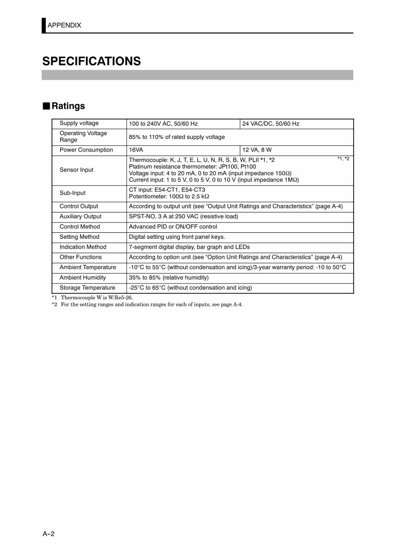
APPENDIX
E5AK
A--2
SPECIFICATIONS
JRatings
Supply voltage 100 to 240V AC, 50/60 Hz 24 VAC/DC, 50/60 Hz
Operating VoltageRange 85% to 110% of rated supply voltage
Power Consumption 16VA 12 VA, 8 W
Sensor Input
Thermocouple: K, J, T, E, L, U, N, R, S, B, W, PLII *1, *2Platinum resistance thermometer: JPt100, Pt100Voltage input: 4 to 20 mA, 0 to 20 mA (input impedance 150Ω)Current input: 1 to 5 V, 0 to 5 V, 0 to 10 V (input impedance 1MΩ)
Sub-Input CT input: E54-CT1, E54-CT3Potentiometer: 100Ω to 2.5 kΩ
Control Output According to output unit (see “Output Unit Ratings and Characteristics” (page A-4)
Auxiliary Output SPST-NO, 3 A at 250 VAC (resistive load)
Control Method Advanced PID or ON/OFF control
Setting Method Digital setting using front panel keys.
Indication Method 7-segment digital display, bar graph and LEDs
Other Functions According to option unit (see “Option Unit Ratings and Characteristics” (page A-4)
Ambient Temperature -10°C to 55°C (without condensation and icing)/3-year warranty period: -10 to 50°C
Ambient Humidity 35% to 85% (relative humidity)
Storage Temperature -25°C to 65°C (without condensation and icing)
*1 Thermocouple W is W/Re5-26.*2 For the setting ranges and indication ranges for each of inputs, see page A-4.
*1, *2

SPECIFICATIONS
E5AK
A--3
JCharacteristics
Indication Accuracy
Thermometer:(±0.3% of indication value or ±1°C, whichever greater) ±1 digit max. (*1)Platinum resistance thermometer:(±0.2% of indication value or± 0.8°C whichever greater) ±1 digit max.Analog input: ±0.2%F±S1 digit max.CT input: 5±%FS ±1 digit max.Potentiometer: ±5%FS±1 digit max.
Temperature variation influence(*2)
Platinum resistance thermometer:(±1% of PV or ± 2°C, whichever greater) ±1 digit max.Thermocouple (R, S, B, W):(±1% of PV or ± 10°C whichever greater) ±1 digit max
Voltage variation influence(*2)
(±1% of PV or ± 10°C, whichever greater) ±1 digit max.Other thermocouples (K1, K2, J1, J2, E, N, T, L1, L2, U, PLII):(±1% of PV or ± 4°C, whichever greater) ±1 digit max.Analog input (current, voltage, or remote SP input): ±1%FS±1 digit max.
Hysteresis 0.01 to 99.99%FS (in units of 0.1%FS)
Proportional Band (P) 0.1 to 999.9%FS (in units of 0.1%FS)
Integral Time (I) 0 to 3999s (in units of 1 second)
Derivative Time (D) 0 to 3999s (in units of 1 second)
Control Period 1 to 99s (in units of 1 second)
Manual Reset Value 0.0 to 100.0% (in units of 0.1%)
Alarm Setting Range -1999 to 9999 (decimal point position dependent on input type)
Sampling Period Temperature input: 250 ms, Analog input: 100 ms, Sub-input: 1s
Program Method Set time or rate of rise programming
Program Size 8 patterns, Max. 16 steps/pattern
Program Time Accuracy ±0.2% ±500 ms of set value (even-numbered steps in the “rate of rise programming” settingare set to the time unit of ramp rate)
Insulation Resistance 20 MΩ min. (at 500 VDC)
Dielectric Strength 2000 VAC, 50/60 Hz for 1 min. (between electrically live terminals of different polarities)
Vibration Malfunction 10 to 55 Hz, 10m/s2 approx. 1G for 10 min. each in X, Y, and Z directionsVibrationResistance Destruction 10 to 55 Hz, 10m/s2 approx. 2G for 2 hrs. each in X, Y, and Z directions
ShockResistance
Malfunction 200 m/s2 min. approx. 20G, 3 times each in 6 directions (100 m/s2 approx. 10G applied tothe relay)
ResistanceDestruction 300 m/s2 min. approx. 30G, 3 times each in 6 directions
Weight Approx. 450 g, mounting bracket: approx. 65 g
Enclosure RatingsFront panel: NEMA4 for indoor use (equivalent to IP66)Fear case: IP20Terminals: IP00
Memory Protection Non-volatile memory (number of writes: 100,000)
*1 The indication accuracy of the K1, T and N thermocouples at a temperature of -100C or less is ±2°C ±1 digit maximum.The indication accuracy of the U, L1 and L2 thermocouples at any temperature is ±2C ±1 digit maximum.The indication accuracy of the B thermocouple at a temperature of 400°C or less is unrestricted.The indication accuracy of the R and S thermocouples at a temperature of 200°C or less is ±3°C ±1 digit maximum.The indication accuracy of the W thermocouple ±1 digit max. of whichever is the greater of ±0.3% or ±3°C of the indi-cated value.The indication accuracy of the PLII thermocouple is ±1 digit max. of whichever is the greater of ±0.3% or ±2°C of theindicated value.
*2 Ambient temperature: ---10°C to 23°C to 55°CVoltage range: ---15 to +10% of rated voltage
*3 On a position-proportional type controllers, 1 to 3999.*4 Changes to parameters and switched remote/local settings are written.
F Heater Burnout AlarmMax. heater current Single-phase 50 A VAC
Heater current value indication accuracy 5%FS1 digit max.
Heater burnout alarm setting range 0.1 to 49.9 A (in units of 0.1 A)
Min. detection ON time 190 ms
*1 0.0 A: The heater burnout alarm turns OFF. 50.0 A: The heater burnout alarm turns ON.*2 No heater burnout detection or heater current value measurement is possible if the control output is ON for less than
190 ms.
(*3)
(*4)
(*1)
(*2)

APPENDIX
E5AK
A--4
JSensor Input Setting Ranges and Indication Ranges
Input Setting Range Indication Range
JPt100 -199.9 to 650.0 (C°) / -199.9 to 999.9 (F°) -199.9 to 735.0 (C°) / -199.9 to 999.9 (F°)
Pt100 -199.9 to 650.0 (C°) / -199.9 to 999.9 (F°) -199.9 to 735.0 (C°) / -199.9 to 999.9 (F°)
K1 -200 to 1300 (C°) / -300 to 2300 (F°) -350 to 1450 (C°) / -560 to 2560 (F°)
K2 -0.0 to 500.0 (C°) / -0.0 to 900.0 (F°) -50.0 to 550.0 (C°) / -90.0 to 990.0 (F°)
J1 -100 to 850 (C°) / -100 to 1500 (F°) -195 to 945 (C°) / -260 to 1660 (F°)
J2 -0.0 to 400.0 (C°) / -0.0 to 750.0 (F°) -40.0 to 440.0 (C°) / -75.0 to 825.0 (F°)
T -199.9 to 400.0 (C°) / -199.9 to 700.0 (F°) -199.9 to 460.0 (C°) / -199.9 to 790.0 (F°)
E 0 to 600 (C°) / -0 to 1100 (F°) -60 to 660.0 (C°) / -110 to 1210 (F°)
L1 -100 to 850 (C°) / -100 to 1500 (F°) -195 to 945 (C°) / -260 to 1660 (F°)
L2 0.0 to 400.0 (C°) / 0.0 to 750.0 (F°) -40.0 to 440.0 (C°) / -75.0 to 825.0 (F°)
U -199.9 to 400.0 (C°) / -199.9 to 700.0 (F°) -199.9 to 650.0 (C°) / -199.9 to 999.9 (F°)
N -200.0 to 1300 (C°) / -300 to 2300 (F°) -199.9 to 460.0 (C°) / -199.9 to 790.0 (F°)
R 0 to 1700 (C°) / 0 to 3000 (F°) -350 to 1450 (C°) / -560 to 2560 (F°)
S 0 to 1700 (C°) / 0 to 3000 (F°) -170 to 1870 (C°) / -300 to 3300 (F°)
B 100 to 1800 (C°) / 300 to 3200 (F°) -170 to 1870 (C°) / -300 to 3300 (F°)
W 0 to 2300 (C°) / 0 to 4100 (F°) -70 to 1970 (C°) / 10 to 3490 (F°)
PL 0 to 1300 (C°) / 0 to 2300 (F°) -230 to 2530 (C°) / -410 to 4510 (F°)
4 to 20mA
0 to 20mA
1 to 5V
0 to 5V
0 to 10V
One of following ranges depending onresults of scaling
-1999 to 9999
-199.9 to 999.9
-19.99 to 99.99
-1.999 to 9.999
-10 to 110% of setting range.Note, however, that max. value is -1999to 9999.
JOutput Unit Ratings and CharacteristicsRatings and characteristics conform to the output unit mounted on thecontroller. For details on the ratings of the output unit, see page 2-7.The relay output unit is already mounted on the E5AK-TPRR[][].(When the output unit is replaced, use the E53-R.)
JOption Unit Ratings and Characteristics
Contact input ON: 1kΩ max., OFF: 100kΩ min.
Event inputsNo-contact input ON: residual voltage 1.5 V max., OFF: leakage current 0.1 mA
max.
Communications
Interface :RS-232C, RS-422 or RS-485
Transmission method :Half-duplex
Synchronization method :Start-stop synchronization (asynchronous method)
Baud rate :1.2/2.4/4.8/9.6/19.2 kbps
Transfer output DC 4 to 20 mA, Permissible load impedance: 600Ω max., Resolution: Approx.2600

ABOUT CURRENT TRANSFORMER (CT)
E5AK
A--5
ABOUT CURRENT TRANSFORMER (CT)
F SpecificationsItem Specifications
Type E54-CT1 E54-CT3
Max. continuous heatercurrent
50A 120A (*1)
Dielectric Strength 1000 VAC (1 min.)
Vibration Resistance 50 Hz, 98 m/s2 10G
Weight Approx. 11.5g Approx. 50g
Accessory - Armature (2), Plug (2)*1 The maximum continuous current of the E5AK-T is 50 A.
F Dimensions2115
2.8
40
30
2-φ3.5
φ5.8
30 φ2.36
φ12
2-M3 depth 4
30
40
j
15
9
1025
3
10.5
7.5
E54-CT1
E54-CT3

APPENDIX
E5AK
A--6
CONTROL BLOCK DIAGRAM
JStandard type
SPlimitter
Program
PV
Temperatureinput
Digital filter
Input shift
Analog input
Digital filter
Scaling
Input type
Control method
Control mode Control mode
ON/OFFcontrol PID control ON/OFF control
3-position control PID control
MV changerate limitter
MV changerate limitter
MV limitter MV limitter
Dead band
MV atPV error
Manual MV
MV at stop
Error
Reset
Manual
Manipulatedvariable(cool)
Manipulatedvariable(heat)
Error
Reset
Manual
Process/function
Control
Data
Heatingside
Coolingside
Heatingside
Coolingside
ResetReset

CONTROL BLOCK DIAGRAM
E5AK
A--7
JPosition-proportional type
SP limitter
Program
PV
Temperatureinput
Input shift
Analog input
Digital filter
Scaling
Input type
PID control
Position-propor-tional dead
band
Error
Stop
Manual
Error
Stop
Manual
Process/function
Control
Data
Digital filter
MV changerrate limitter
Open side Closed side
Operation atPV error
Operation atreset
Manualoperation
Openoutput
Closedoutput

APPENDIX
E5AK
A--8
SETTING LIST
Mode Parameter Name Setting Range Unit Default Remarks Setting
ProtectSecurity 0 to 6 None 1
ProtectKey protect 0/1/2/3 None 0
Manual Manual MV -5.0 to 105.0*1 % 0.0
Pattern No. 0 to 7 None 0
Level 0 Hold OFF/ON None OFF At program opera-tion
Advance OFF/ON None OFF At program opera-tion
Pattern No. 0 to 7 None 0
Number of steps 1 to 16 None 8
toSteps 0 to 15 SP/Target SP 0 to 7 SP lower limit to SP upper limit EU 0
to Ramp rate 0 to 7 0 to 9999 *3 0
toStep 0 to 15 time/Soak time 0 to 7 0.00 to 99.59 *4 0.00
Pattern executioncount 0 to 9999 Times 1
Program Alarm value 1 -1999 to 9999 EU 0ProgramAlarm value 2 -1999 to 9999 EU 0
Alarm value 3 -1999 to 9999 EU 0
Time signal 1 enabledstep 0 to 15 None 0
Time signal 1 ON time 0.00 to 99.59 *4 0.00
Time signal 1 OFFtime 0.00 to 99.59 *4 0.00
Time signal 2 enabledstep 0 to 15 None 0
Time signal 2 ON time 0.00 to 99.59 *4 0.00
Time signal 2 OFFtime 0.00 to 99.59 *4 0.00
AT Execute/Cancel OFF/ AT-1/AT-2 None OFF
Proportional band 0.1 to 999.9 %FS 10.0
Integral time 0 to 3999 sec 233
Derivative time 0 to 3999 sec 40
Cooling coefficient 0.01 to 99.99 None 1.00 At heating andcooling control
Dead band -19.99 to 99.99 %FS 0.00 At heating andcooling control
Level 1Position-proportionaldead band 0.1 to 10.0 % 2.0 At position-propor-
tional control
Manual reset value 0.0 to 100.0 % 50.0
Hysteresis (heat) 0.01 to 99.99 %FS 0.10
Hysteresis (cool) 0.01 to 99.99 %FS 0.10 At heating andcooling control
Control period (heat) 1 to 99 sec 20
Control period (cool) 1 to 99 sec 20 At heating andcooling control
Heater burnout 0.0 to 50.0 A 0.0 Heater burnoutdetection
*2
*2
*2
*1
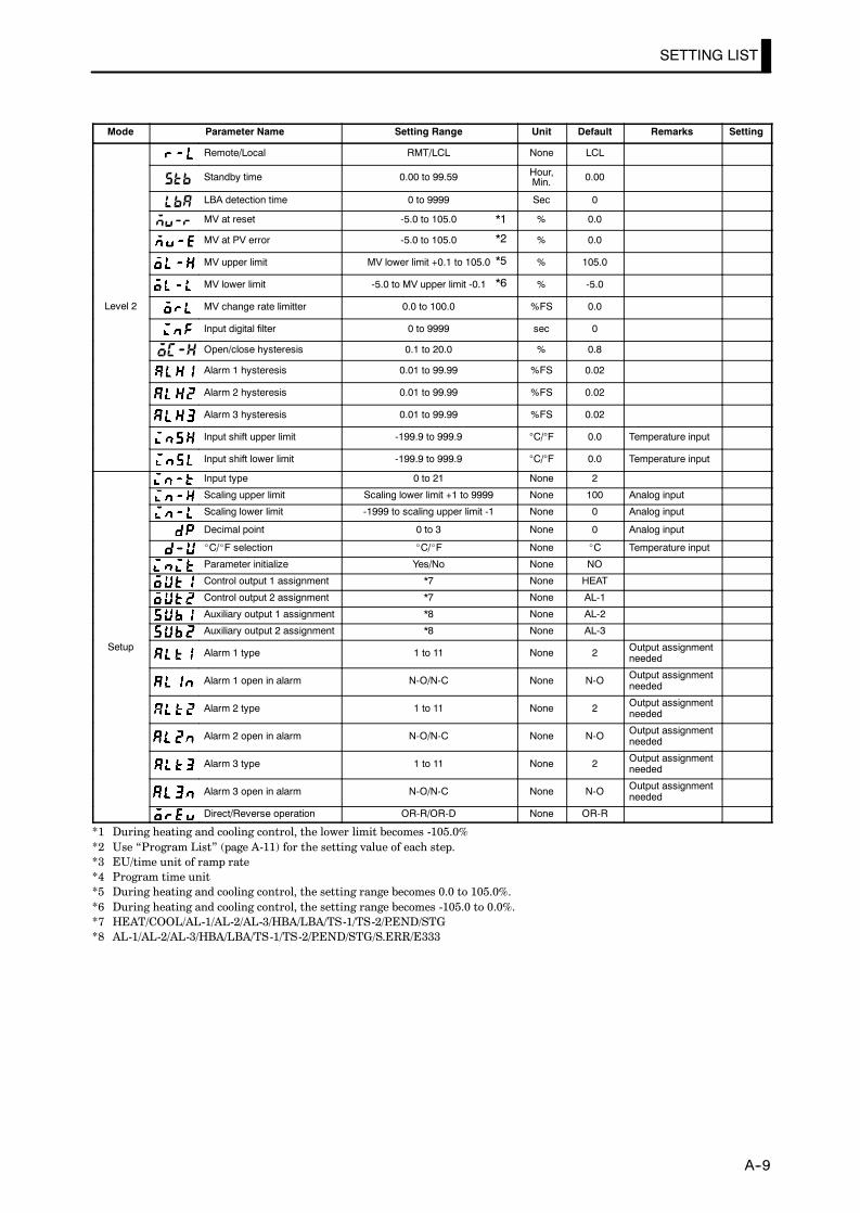
SETTING LIST
E5AK
A--9
Mode Parameter Name Setting Range Unit Default Remarks Setting
Remote/Local RMT/LCL None LCL
Standby time 0.00 to 99.59 Hour,Min. 0.00
LBA detection time 0 to 9999 Sec 0
MV at reset -5.0 to 105.0 % 0.0
MV at PV error -5.0 to 105.0 % 0.0
MV upper limit MV lower limit +0.1 to 105.0 % 105.0
MV lower limit -5.0 to MV upper limit -0.1 % -5.0
Level 2 MV change rate limitter 0.0 to 100.0 %FS 0.0
Input digital filter 0 to 9999 sec 0
Open/close hysteresis 0.1 to 20.0 % 0.8
Alarm 1 hysteresis 0.01 to 99.99 %FS 0.02
Alarm 2 hysteresis 0.01 to 99.99 %FS 0.02
Alarm 3 hysteresis 0.01 to 99.99 %FS 0.02
Input shift upper limit -199.9 to 999.9 °C/°F 0.0 Temperature input
Input shift lower limit -199.9 to 999.9 °C/°F 0.0 Temperature input
Input type 0 to 21 None 2
Scaling upper limit Scaling lower limit +1 to 9999 None 100 Analog input
Scaling lower limit -1999 to scaling upper limit -1 None 0 Analog input
Decimal point 0 to 3 None 0 Analog input
_C/_F selection _C/_F None _C Temperature input
Parameter initialize Yes/No None NO
Control output 1 assignment *7 None HEAT
Control output 2 assignment *7 None AL-1
Auxiliary output 1 assignment *8 None AL-2
Auxiliary output 2 assignment *8 None AL-3
Setup Alarm 1 type 1 to 11 None 2 Output assignmentneeded
Alarm 1 open in alarm N-O/N-C None N-O Output assignmentneeded
Alarm 2 type 1 to 11 None 2 Output assignmentneeded
Alarm 2 open in alarm N-O/N-C None N-O Output assignmentneeded
Alarm 3 type 1 to 11 None 2 Output assignmentneeded
Alarm 3 open in alarm N-O/N-C None N-O Output assignmentneeded
Direct/Reverse operation OR-R/OR-D None OR-R
*1 During heating and cooling control, the lower limit becomes -105.0%*2 Use “Program List” (page A-11) for the setting value of each step.*3 EU/time unit of ramp rate*4 Program time unit*5 During heating and cooling control, the setting range becomes 0.0 to 105.0%.*6 During heating and cooling control, the setting range becomes -105.0 to 0.0%.*7 HEAT/COOL/AL-1/AL-2/AL-3/HBA/LBA/TS-1/TS-2/P.END/STG*8 AL-1/AL-2/AL-3/HBA/LBA/TS-1/TS-2/P.END/STG/S.ERR/E333
*1
*2
*5
*6

APPENDIX
E5AK
A--10
Mode Parameter Name Setting Range Unit Default Remarks Setting
Set point upper limit Set point lower limit +1 to scaling upper limit EU 1300
Set point lower limit Scaling lower limit to Set point upper limit -1 EU -200
PID / ON/OFF PID / ON/OFF None PID
Operation at power ON CON/RST/RUN/MAN None CON
End condition RST/SP None RST
Program time unit HHMM/MMSS None HHMM
Step time/Rate of rise pro-gramming TIME/PR None OFF
Time unit of ramp rate M/H None OFF
Expan-i
PV start PV/SP None SPExpansion Wait width 0 to 9999 EU 0
Alarm during ramp step en-able ON/OFF None ON
Run all enable ON/OFF None OFF
α 0.00 to 1.00 None 0.65
AT calculated gain 0.1 to 10.0 None 1.0
Automatic return of displaymode 0 to 99 Sec 0
AT hysteresis 0.1 to 9.9 %FS 0.2
LB detection width 0.0 to 999.9 %FS 0.2
Event input assignment 1 NON/RST/MAN/HOLD/ADV/PTN0 to 2 None NON
Event input assignment 2 NON/RST/MAN/HOLD/ADV/PTN0 to 2 None NON
Event input assignment 3 NON/RST/RMT/MAN/HOLD/ADV/PTN0 to 2 None NON
Event input assignment 4 NON/RST/RMT/MAN/HOLD/ADV/PTN0 to 2 None NON
Communication stop bit 1/2 bit 2
Communication data length 7/8 bit 7
Communication parity NONE/EVEN/ODD None EVEN
OptionCommunication baud rate 1.2/2.4/4.8/9.6/19.2 kbps 9.6
OptionCommunication unit No. 0 to 99 None 0
Transfer output type SP/PV/O/C-O/V-M None SP
Transfer output upper limit *11 *11 *10
Transfer output lower limit *11 *11 *10
HBA latch ON/OFF None OFF
Motor calibration ON/OFF None OFF
Travel time 1 to 999 Sec 30
PV dead band 0 to 9999 EU 0
*9 When temperature input is selected, the range of the sensor selected in the “input type” parameter (setup mode) correspondsto the scaling upper and lower limit value.
*10 Set the transfer output type parameter according to the following table.
Transfer Output Type Transfer Output Lower Limit to Transfer Output Upper Limit
SP :Present SP -1999 to 9999
PV :Process value -1999 to 9999
O :Manipulated variable (heat) -5.0 to 105.0% (standard control), 0.0 to 105.0% (heating and cooling control)
C-O :Manipulated variable (cool) 0.0 to 105.0%
V-M :Valve opening -10.0 to 110.0%
D Default : [SP]
*9*9

SETTING LIST
E5AK
A--11

APPENDIX
E5AK
A--12
MODEL LIST
Description Type Name Specification
Base unit E5AK-TAA2 AC100-240 Standard model
E5AK-TAA2-500 AC100-240 Standard model with terminal cover
E5AK-TAA2 AC/DC24 Standard model
E5AK-TAA2-500 AC/DC24 Standard model with terminal cover
E5AK-TPRR2 AC100-240 Position-proportional model
E5AK-TPRR2-500 AC100-240 Position-proportional model with terminal cover
E5AK-TPRR2 AC/DC24 Position-proportional model
E5AK-TPRR2-500 AC/DC24 Position-proportional model with terminal cover
Option unit E53-AKB Event input
E53-AK01 Communication (RS-232C)
E53-AK02 Communication (RS-422)
E53-AK03 Communication (RS-485)
E53-AKF Transfer output
Output unit E53-R Relay
E53-S SSR
E53-Q Pulse (NPN) DC12V
E53-Q3 Pulse (NPN) DC24V
E53-Q4 Pulse (PNP) DC24V
E53-C3 Linear (4 to 20mA)
E53-C3D Linear (0 to 20mA)
E53-V34 Linear (0 to 10V)
E53-V35 Linear (0 to 5V)
Terminal cover E53-COV0809 for E5AK

PARAMETER OPERATIONS LIST
E5AK
A--13
PARAMETER OPERATIONS LIST
• Switching to modes other than the manual or protect mode is carried out by mode selection inthe menu display.
• The figure below shows all parameters in the order that they are displayed. Some parameters arenot displayed depending on the protect mode setting and conditions of use.
Level 0
Program
1 second min.
Manual mode
Protect mode
Parameters in a mode can beswitched by the key. The param-eter following the last parameter is thetop parameter of the mode.
Power ON
1 second min.
1 second min.
1 second min.
1 second min.
1 second min.
1 second min.
1 second min.
1 second min.
Level 1
Level 2
Setup mode
Expansionmode
Option mode
Calibrationmode
1 second min.
1 second min.1 second min.
1 second min.
+
+
+
+
RUN/RST
RUN/RST
RUN/RST
Level 0 Program Level 1
PV/Present SP Pattern No. AT Execute/Cancel
Pattern No. Number of steps Proportional band
Step No. monitor to Step 0 to 7 SP Integral time
Hold to Ramp rate 0 to 7 Derivative time
Advance to Step 0 to 7 time Cooling coefficient
Standby time monitor to Step 8 to 15 SP Dead band
Pattern elapsing time monitor to Step 8 to 15 time Position-proportional dead band
Pattern execution count monitor Pattern execution count Manual reset value
MV monitor (heat) Alarm value 1 Hysteresis (heat)
MV monitor (cool) Alarm value 2 Hysteresis (cool)
Valve opening monitor Alarm value 3 Control period (heat)
Time signal 1 step selection Control period (cool)
Time signal 1 ON time Heater current monitor
Time signal 1 OFF time Heater burnout
Time signal 2 step selection
Time signal 2 ON time
Time signal 2 OFF time
*1
*1
*1In the rate of rise setting, Target SP 0to 7 and Soak time 0 to 7.

APPENDIX
E5AK
A--14
Level 2 Setup Expansion
Remote/Local Input type Set point upper limit
Standby time Scaling upper limit Set point lower limit
LBA detection time Scaling lower limit PID / ON/OFF
MV at reset Decimal point Operation at power ON
MV at PV error °C/°F selection End condition
MV upper limit Parameter initialize Program time unit
MV lower limit Control output 1 assignment Step time/Rate of rise programming
MV change rate limit Control output 2 assignment Time unit of ramp rate
Input digital filter Auxiliary output 1 assignment PV start
Open/Close hysteresis Auxiliary output 2 assignment Wait width
Alarm 1 hysteresis Alarm 1 type Alarm during ramp step enable
Alarm 2 hysteresis Alarm 1 open in alarm Run all enable
Alarm 3 hysteresis Alarm 2 type α
Input shift upper limit Alarm 2 open in alarm AT calculated gain
Input shift lower limit Alarm 3 type Automatic return of display mode
Alarm 3 open in alarm AT hysteresis
Direct/Reverse operation LBA detection width
Option Calibration
Event input assignment 1 For details, refer to Chapter 7 Calibra-tion/7 1 Structure of Parameters” (page
Event input assignment 2tion/7.1 Structure of Parameters” (page7-2).
Event input assignment 3 ManualEvent input assignment 4
Manual
Communication stop bit Manual MV
Communication data length
Communication parity ProtectCommunication baud rate
Protect
Communication unit No. Security
Transfer output type Key protect
Transfer output upper limit
Transfer output lower limit
HBA latch
Motor calibration
Travel time
PV dead band

ASCII CODE LIST
E5AK
A--15
ASCII CODE LIST
Hex 0 1 2 3 4 5 6 7
Bin 0000 0001 0010 0011 0100 0101 0110 0111
0 0000 SP 0 @ P p
1 0001 ! 1 A Q a q
2 0010 ” 2 B R b r
3 0011 # 3 C S c s
4 0100 $ 4 D T d t
5 0101 % 5 E U e u
6 0110 & 6 F V f v
7 0111 ’ 7 G W g w
8 1000 ( 8 H X h x
9 1001 ) 9 I Y i y
A 1010 * : J Z j z
B 1011 + ; K [ k
C 1100 , < L ¥ l |
D 1101 - = M ] m
E 1110 . > N ^ n ~
F 1111 / ? O _ o DEL
Upper 4 bits
Lower 4 bits

INDEX
E5AK
Symbols° C/° F selection 5---33. . . . . . . . . . . . . . . . . . . . .
Numbers100%AT 3---25. . . . . . . . . . . . . . . . . . . . . . . . . . .40%AT 3---25. . . . . . . . . . . . . . . . . . . . . . . . . . . . .
AA group 6---11. . . . . . . . . . . . . . . . . . . . . . . . . . . .A/D converter error 8---3, 8---5. . . . . . . . . . . . .A/M key 1---4. . . . . . . . . . . . . . . . . . . . . . . . . . . . .About Calibration 1---13. . . . . . . . . . . . . . . . . . .About Changing the Number of Steps 3---22.ABOUT CURRENTTRANSFORMER (CT) A---5. . . . . . . . . . .
About Errors That Occur During MotorCalibration 8---4. . . . . . . . . . . . . . . . . . . . . . .
About invalid parameters 6---5. . . . . . . . . . . . .About Isolation 2---10. . . . . . . . . . . . . . . . . . . . .About ON conditions 4---17. . . . . . . . . . . . . . . .About parameter display 5---2. . . . . . . . . . . . . .About Pattern Elapsing Time 4---17. . . . . . . .About PID Parameters 3---26. . . . . . . . . . . . . .About Reset 4---15. . . . . . . . . . . . . . . . . . . . . . . .About the Alarm Value Decimal Point 3---16.About the Communications Function 1---12.About the displays 1---3. . . . . . . . . . . . . . . . . . .About the Order in Which Parametersare Described in This Chapter 5---2. . . . . .
About the Unit No. 6---15. . . . . . . . . . . . . . . . . .Advance 4---22, 5---8. . . . . . . . . . . . . . . . . . . . . .Alarm 1 hysteresis 5---29. . . . . . . . . . . . . . . . . .Alarm 1 open in alarm 5---37. . . . . . . . . . . . . . .Alarm 1 type 5---36. . . . . . . . . . . . . . . . . . . . . . .Alarm 2 hysteresis 5---29. . . . . . . . . . . . . . . . . .Alarm 2 open in alarm 5---37. . . . . . . . . . . . . . .Alarm 2 type 5---36. . . . . . . . . . . . . . . . . . . . . . .Alarm 3 hysteresis 5---29. . . . . . . . . . . . . . . . . .Alarm 3 open in alarm 5---37. . . . . . . . . . . . . . .Alarm 3 type 5---36. . . . . . . . . . . . . . . . . . . . . . .Alarm hysteresis 3---11. . . . . . . . . . . . . . . . . . . .Alarm type 3---10. . . . . . . . . . . . . . . . . . . . . . . . .Alarm value 3---10, 3---16. . . . . . . . . . . . . . . . . .Alarm value 1 5---14. . . . . . . . . . . . . . . . . . . . . .Alarm value 2 5---14. . . . . . . . . . . . . . . . . . . . . .Alarm value 3 5---14. . . . . . . . . . . . . . . . . . . . . .Alfa 5---44. . . . . . . . . . . . . . . . . . . . . . . . . . . . . . .Analog input 3---5. . . . . . . . . . . . . . . . . . . . . . . .ASCII CODE LIST A---15. . . . . . . . . . . . . . . . .AT Execute/Cancel 5---18. . . . . . . . . . . . . . . . . .AT Execution Timing 3---26. . . . . . . . . . . . . . .
Auto---tuning (A.T.) 3---25. . . . . . . . . . . . . . . . .Auto---turning key 1---4. . . . . . . . . . . . . . . . . . .Auto/Manual 4---22. . . . . . . . . . . . . . . . . . . . . . .Auxiliary output 2---10. . . . . . . . . . . . . . . . . . . .Auxiliary output 1 assignment 5---35. . . . . . . .Auxiliary output 2 assignment 5---35. . . . . . . .
BB group 6---11. . . . . . . . . . . . . . . . . . . . . . . . . . . .Balance---less, Bump---less Operation 3---24. .Bar graph 1---3. . . . . . . . . . . . . . . . . . . . . . . . . . .Basic Operation Flow 3---2. . . . . . . . . . . . . . . . .Before setup 2---3, 2---4. . . . . . . . . . . . . . . . . . . .
CCable connections 6---3. . . . . . . . . . . . . . . . . . . .Calibrating Current Input 7---9. . . . . . . . . . . .Calibrating inputs 1---13. . . . . . . . . . . . . . . . . .Calibrating Platinum ResistanceThermometers 7---7. . . . . . . . . . . . . . . . . . . . . . .Calibrating Thermocouples 7---4. . . . . . . . . . .Calibrating transfer output 1---13. . . . . . . . . .Calibrating Voltage Input 7---10. . . . . . . . . . . .Calibration 7---7, 7---9. . . . . . . . . . . . . . . . . . . . .Calibration data error 8---4. . . . . . . . . . . . . . . .Calibration item menu 7---3. . . . . . . . . . . . . . .Calibration Mode 1---10. . . . . . . . . . . . . . . . . . .Calibration: 0 to 10V 7---11. . . . . . . . . . . . . . . .Calibration: 0 to 5V, 1 to 5V 7---10. . . . . . . . . .Calibration: thermocouple 1 7---5. . . . . . . . . . .Calibration: thermocouple 2 7---6. . . . . . . . . . .Changing currently running programs 3---22Changing parameters 4---11. . . . . . . . . . . . . . . .Changing the SP 3---22. . . . . . . . . . . . . . . . . . . .Changing the time value 3---22. . . . . . . . . . . . .Characteristics A---3. . . . . . . . . . . . . . . . . . . . .Checking Indication Accuracy 7---12. . . . . . . .Checking indication accuracy 7---12. . . . . . . . .Checking Operation Restrictions 8---6. . . . . .Close in alarm/open in alarm 3---11. . . . . . . . .Command Structure 6---5. . . . . . . . . . . . . . . . . .Commands and Responses 6---7. . . . . . . . . . . .Communication baud rate 5---48. . . . . . . . . . .Communication data length 5---48. . . . . . . . . .Communication parity 5---48. . . . . . . . . . . . . . .Communication stop bit 5---48. . . . . . . . . . . . .Communication unit No. 5---48. . . . . . . . . . . . .Communications 2---11. . . . . . . . . . . . . . . . . . . .Communications parameters 6---4. . . . . . . . . .Conditions when running a program 6---17. .Connecting the ColdJunction Compensator 7---4. . . . . . . . . . . . .

INDEX
E5AK
CONTROL BLOCK DIAGRAM A---6. . . . . . .Control output 2---9. . . . . . . . . . . . . . . . . . . . . . .Control output 1 assignment 5---34. . . . . . . . .Control output 2 assignment 5---34. . . . . . . . .Control period 3---8. . . . . . . . . . . . . . . . . . . . . . .Control period (cool) 5---22. . . . . . . . . . . . . . . .Control period (heat) 5---22. . . . . . . . . . . . . . . .Convention Used in this Chapter 3---2. . . . . .Conventions Used in this Chapter 5---2. . . . .Cooling coefficient 4---2, 5---19. . . . . . . . . . . . .CT input/Potentiometer 1---5, 2---10. . . . . . . .Current input 1---5, 7---13. . . . . . . . . . . . . . . . .
DDead band 4---2, 5---19. . . . . . . . . . . . . . . . . . . . .Decimal point 5---32. . . . . . . . . . . . . . . . . . . . . .Derivative time 5---18. . . . . . . . . . . . . . . . . . . . .Detailed description of input functions 4---22Determining the LBA detection time 4---27. .Dimensions 2---5, A---5. . . . . . . . . . . . . . . . . . . .Direct/Reverse operation 3---8, 5---37. . . . . . . .Display range over 8---4. . . . . . . . . . . . . . . . . . .Down key 1---4. . . . . . . . . . . . . . . . . . . . . . . . . . .Draw---out 2---2. . . . . . . . . . . . . . . . . . . . . . . . . . .
EEnd code 6---15. . . . . . . . . . . . . . . . . . . . . . . . . . .End condition 4---20, 5---40. . . . . . . . . . . . . . . .Event input 1---6, 2---11. . . . . . . . . . . . . . . . . . .Event input assignment 1 5---47. . . . . . . . . . . .Event input assignment 2 5---47. . . . . . . . . . . .Event input assignment 3 5---47. . . . . . . . . . . .Event input assignment 4 5---47. . . . . . . . . . . .Examples of use 4---25, 6---19. . . . . . . . . . . . . . .Executing all patterns 4---14. . . . . . . . . . . . . . .Expansion Mode 1---10, 5---38. . . . . . . . . . . . . .
FFixing Screw for Front Panel 2---2. . . . . . . . . .Fixing settings 1---11. . . . . . . . . . . . . . . . . . . . . .Front panel 1---2. . . . . . . . . . . . . . . . . . . . . . . . .
HHBA latch 5---50. . . . . . . . . . . . . . . . . . . . . . . . . .HBA latch/release 4---23. . . . . . . . . . . . . . . . . . .Heater burnout 5---23. . . . . . . . . . . . . . . . . . . . .Heater Burnout Alarm A---3. . . . . . . . . . . . . .Heater burnout detection 4---23. . . . . . . . . . . .Heater current monitor 5---23. . . . . . . . . . . . . .Heating and cooling control 4---2. . . . . . . . . . .Hold 5---8. . . . . . . . . . . . . . . . . . . . . . . . . . . . . . . .
Hold/advance 4---13. . . . . . . . . . . . . . . . . . . . . . .Hold/Hold cancel 4---22. . . . . . . . . . . . . . . . . . . .How the program works 4---12. . . . . . . . . . . . .How to Calculate FCS 6---6. . . . . . . . . . . . . . . .How to calculate theheater burnout set value 4---24. . . . . . . . . .
How to Read CommunicationsError Information 6---15. . . . . . . . . . . . . . . .
How to use keys 1---4. . . . . . . . . . . . . . . . . . . . . .How to use programs 6---17. . . . . . . . . . . . . . . .How to Use the Error Display 8---3. . . . . . . . .How to Use the Error Output 8---5. . . . . . . . .How to Use theHeater Burnout Alarm 4---23. . . . . . . . . . . .
How to Use Transfer Output 4---28. . . . . . . . .Hysteresis 4---5. . . . . . . . . . . . . . . . . . . . . . . . . . .Hysteresis (cool) 5---21. . . . . . . . . . . . . . . . . . . .Hysteresis (heat) 5---21. . . . . . . . . . . . . . . . . . . .
IInitial Checks 8---2. . . . . . . . . . . . . . . . . . . . . . . .Input and Output 1---5. . . . . . . . . . . . . . . . . . . .Input assignments 4---21. . . . . . . . . . . . . . . . . .Input digital filter 5---28. . . . . . . . . . . . . . . . . . .Input error 8---3. . . . . . . . . . . . . . . . . . . . . . . . . .Input errors 8---5. . . . . . . . . . . . . . . . . . . . . . . . .Input shift lower limit 5---29. . . . . . . . . . . . . . .Input shift upper limit 5---29. . . . . . . . . . . . . . .Input type 3---4, 5---31. . . . . . . . . . . . . . . . . . . . .Installation 2---5. . . . . . . . . . . . . . . . . . . . . . . . . .Integral time 5---18. . . . . . . . . . . . . . . . . . . . . . .Interface 6---2. . . . . . . . . . . . . . . . . . . . . . . . . . . .Issuing special commands 6---10. . . . . . . . . . . .
KKey protect 3---19, 5---4. . . . . . . . . . . . . . . . . . . .
LLBA 4---26, 8---5. . . . . . . . . . . . . . . . . . . . . . . . . .LBA detection example 4---26. . . . . . . . . . . . . .LBA detection time 4---26, 5---26. . . . . . . . . . . .LBA detection width 4---26. . . . . . . . . . . . . . . .Level 0 Mode 1---9, 5---6. . . . . . . . . . . . . . . . . . .Level 1 Mode 1---9, 5---17. . . . . . . . . . . . . . . . . .Level 2 Mode 1---9, 5---24. . . . . . . . . . . . . . . . . .Limiter operation conditions 4---8. . . . . . . . . .
MMain parts 1---2. . . . . . . . . . . . . . . . . . . . . . . . . .Manipulated variable at reset 4---3. . . . . . . . .Manipulated variable at reset/PV error 4---4.Manipulated variable at stop 3---21. . . . . . . . .Manipulated variable restrictions 4---7. . . . . .

INDEX
E5AK
Manual Mode 1---9, 5---5. . . . . . . . . . . . . . . . . . .Manual MV 5---5. . . . . . . . . . . . . . . . . . . . . . . . .Manual reset value 5---20. . . . . . . . . . . . . . . . . .Memory error 8---3. . . . . . . . . . . . . . . . . . . . . . .MODEL LIST A---12. . . . . . . . . . . . . . . . . . . . .Monitor process value 6---19. . . . . . . . . . . . . . .Motor calibration 5---50. . . . . . . . . . . . . . . . . . .Mounting 2---6. . . . . . . . . . . . . . . . . . . . . . . . . . .MV at PV error 5---26. . . . . . . . . . . . . . . . . . . . .MV at reset 5---26. . . . . . . . . . . . . . . . . . . . . . . . .MV change rate limit 5---27. . . . . . . . . . . . . . . .MV change rate limiter 4---7. . . . . . . . . . . . . . .MV limiter 4---7. . . . . . . . . . . . . . . . . . . . . . . . . .MV lower limit 5---27. . . . . . . . . . . . . . . . . . . . .MV monitor (cool) 5---10. . . . . . . . . . . . . . . . . .MV monitor (heat) 5---10. . . . . . . . . . . . . . . . . .MV upper limit 5---27. . . . . . . . . . . . . . . . . . . . .
NNames of parts 1---2. . . . . . . . . . . . . . . . . . . . . .No.1 display 1---3. . . . . . . . . . . . . . . . . . . . . . . . .No.2 display 1---3. . . . . . . . . . . . . . . . . . . . . . . . .Number of steps 3---15, 5---12. . . . . . . . . . . . . .
OON/OFF control 4---5. . . . . . . . . . . . . . . . . . . . .Open/close hysteresis 5---28. . . . . . . . . . . . . . . .Operating Condition Restrictions 4---7. . . . . .Operating conditions 4---23. . . . . . . . . . . . . . . .Operation at Input Error 4---12. . . . . . . . . . . .Operation at power ON 4---19, 5---40. . . . . . . .Operation indicator LEDs 1---3. . . . . . . . . . . .Option Mode 1---10, 5---46. . . . . . . . . . . . . . . . .Option Unit Ratings andCharacteristics A---4. . . . . . . . . . . . . . . . . . .
Other functions 4---4. . . . . . . . . . . . . . . . . . . . . .Outline 6---2. . . . . . . . . . . . . . . . . . . . . . . . . . . . .Outline of the CommunicationsFunction 6---2. . . . . . . . . . . . . . . . . . . . . . . . .
Output 1---6. . . . . . . . . . . . . . . . . . . . . . . . . . . . . .Output assignments 1---6, 3---7. . . . . . . . . . . . .Output Unit Ratings andCharacteristics A---4. . . . . . . . . . . . . . . . . . .
PPanel cutout 2---5. . . . . . . . . . . . . . . . . . . . . . . . .Parameter initialize 5---33. . . . . . . . . . . . . . . . .PARAMETER OPERATIONS LIST A---13. .Parameter Structure 7---2. . . . . . . . . . . . . . . . .Parameter types 1---9. . . . . . . . . . . . . . . . . . . . .Parameters and Menus 1---9. . . . . . . . . . . . . . .
Pattern elapsing time 5---9. . . . . . . . . . . . . . . . .Pattern execution count 5---14. . . . . . . . . . . . .Pattern execution count monitor 5---9. . . . . .Pattern No. 1---3, 3---15, 5---7. . . . . . . . . . . . . . .Pattern operation 4---14. . . . . . . . . . . . . . . . . . .Pattern select 4---22. . . . . . . . . . . . . . . . . . . . . . .PID/ON/OFF 5---39. . . . . . . . . . . . . . . . . . . . . . .Platinum resistance thermometer 7---12. . . .Position---proportional control 4---4. . . . . . . .Position---proportional type 3---8, 3---24. . . . .Position-proportional dead band 5---20. . . . . .Position-proportional type A---7. . . . . . . . . . .Power supply 2---8. . . . . . . . . . . . . . . . . . . . . . . .Precautions when wiring 2---8. . . . . . . . . . . . .Preparation 7---7, 7---9, 7---10. . . . . . . . . . . . . .Preparations 7---4. . . . . . . . . . . . . . . . . . . . . . . .Preparing for Communications 6---3. . . . . . . .Procedure 2---3, 2---4, 6---17. . . . . . . . . . . . . . . .Program 1---8. . . . . . . . . . . . . . . . . . . . . . . . . . . .Program end 4---18. . . . . . . . . . . . . . . . . . . . . . .Program Example 6---17. . . . . . . . . . . . . . . . . . .Program example 4---12. . . . . . . . . . . . . . . . . . .Program list 6---18. . . . . . . . . . . . . . . . . . . . . . . .Program Mode 5---11. . . . . . . . . . . . . . . . . . . . . .Program mode 1---9. . . . . . . . . . . . . . . . . . . . . . .Program Operation 4---13. . . . . . . . . . . . . . . . .Program output 4---17, 4---18. . . . . . . . . . . . . .Program status indicators 1---3. . . . . . . . . . . .Program structure 4---12. . . . . . . . . . . . . . . . . .Proportional band 5---18. . . . . . . . . . . . . . . . . .Protect Mode 1---9, 3---19, 5---3. . . . . . . . . . . . .PV dead band 5---51. . . . . . . . . . . . . . . . . . . . . . .PV start 4---20, 5---42. . . . . . . . . . . . . . . . . . . . . .PV/Present SP 5---6. . . . . . . . . . . . . . . . . . . . . . .
RRamp rate 0 5---13. . . . . . . . . . . . . . . . . . . . . . . .Ramp rate 7 5---13. . . . . . . . . . . . . . . . . . . . . . . .Ramp Rise Rate Setup Program 4---9. . . . . . .Reading parameters 6---7, 6---12. . . . . . . . . . . .Reading/writing parameters 6---7. . . . . . . . . . .Reading/writing program parameters 6---12.Registering calibration data 1---13. . . . . . . . . .Relationship with the number of steps 4---10.Remote/Local 4---22, 5---25. . . . . . . . . . . . . . . . .Repeating execution of thesame pattern 4---14. . . . . . . . . . . . . . . . . . . .
RS---232C 1---12, 6---3. . . . . . . . . . . . . . . . . . . . .RS---422 1---12, 6---3. . . . . . . . . . . . . . . . . . . . . . .RS---485 1---12, 6---4. . . . . . . . . . . . . . . . . . . . . . .Run/Reset 4---22. . . . . . . . . . . . . . . . . . . . . . . . . .

INDEX
E5AK
Running the ramp riserate setup program 4---11. . . . . . . . . . . . . . .
SScaling lower limit 5---32. . . . . . . . . . . . . . . . . .Scaling upper limit 5---32. . . . . . . . . . . . . . . . . .Security 3---19, 5---3. . . . . . . . . . . . . . . . . . . . . . .Selecting modes 1---10. . . . . . . . . . . . . . . . . . . . .Selecting parameters 1---11. . . . . . . . . . . . . . . .Selecting the Control Method 4---2. . . . . . . . . .Sensor input 2---9. . . . . . . . . . . . . . . . . . . . . . . . .Sensor Input Setting Rangesand Indication Ranges A---4. . . . . . . . . . . .
Set point limiter 4---8. . . . . . . . . . . . . . . . . . . . .Set point lower limit 5---39. . . . . . . . . . . . . . . .Set point upper limit 5---39. . . . . . . . . . . . . . . .Set the set point to “300.0” 6---19. . . . . . . . . . .Setting Alarm Type 3---10. . . . . . . . . . . . . . . . .Setting Input Specifications 3---4. . . . . . . . . . .SETTING LIST A---8. . . . . . . . . . . . . . . . . . . .Setting Output Specifications 3---7. . . . . . . . .Setting Patterns 3---14. . . . . . . . . . . . . . . . . . . .Setting Running Conditions 4---19. . . . . . . . . .Setting the communicationsspecifications 6---4. . . . . . . . . . . . . . . . . . . . .
Setting the LBA detection time 4---27. . . . . . .Setting up the option unit 2---4. . . . . . . . . . . . .Setting up the output unit 2---3. . . . . . . . . . . .Setting up the terminal covers 2---7. . . . . . . . .Setup 2---2. . . . . . . . . . . . . . . . . . . . . . . . . . . . . . .Setup examples 3---3. . . . . . . . . . . . . . . . . . . . . .Setup Mode 1---9, 5---30. . . . . . . . . . . . . . . . . . .SPECIFICATIONS A---2. . . . . . . . . . . . . . . . . .Specifications A---5. . . . . . . . . . . . . . . . . . . . . . .Stage output 4---18. . . . . . . . . . . . . . . . . . . . . . . .Standard type 3---7, 3---24, A---6. . . . . . . . . . . .Standby operation 4---20. . . . . . . . . . . . . . . . . .Standby sequence 3---11. . . . . . . . . . . . . . . . . . .Standby time 5---25. . . . . . . . . . . . . . . . . . . . . . .Standby time monitor 5---9. . . . . . . . . . . . . . . .Start running 6---19. . . . . . . . . . . . . . . . . . . . . . .Starting and Stopping Operation 3---21. . . . .Starting the program run 4---20. . . . . . . . . . . .Step 0 time (Step time) 5---12, 5---13. . . . . . . .Step 15 SP (Step time) 5---12. . . . . . . . . . . . . . .Step 15 time (Step time) 5---13. . . . . . . . . . . . .Step 7 SP (Step time) 5---12. . . . . . . . . . . . . . . .Step 7 time (Step time) 5---13. . . . . . . . . . . . . .
Step 8 SP (Step time) 5---12. . . . . . . . . . . . . . . .Step 8 time (Step time) 5---13. . . . . . . . . . . . . .Step No. monitor 5---7. . . . . . . . . . . . . . . . . . . . .Step operation 1---8. . . . . . . . . . . . . . . . . . . . . . .Step SP/Step time 3---15. . . . . . . . . . . . . . . . . . .Summary of alarm operations 3---12. . . . . . . .Switching with Manual Operation 4---3. . . . .
TTemperature input 1---5, 3---5. . . . . . . . . . . . . .Temperature input shift 3---5. . . . . . . . . . . . . .Temperature unit 3---5. . . . . . . . . . . . . . . . . . . .Terminal arrangement 2---8. . . . . . . . . . . . . . .The meaning of icons usedin this chapter 5---2. . . . . . . . . . . . . . . . . . . .
Thermocouple 7---12. . . . . . . . . . . . . . . . . . . . . .Time signal 4---17. . . . . . . . . . . . . . . . . . . . . . . .Time signal 1 enabled step 5---15. . . . . . . . . . .Time signal 1 OFF time 5---16. . . . . . . . . . . . .Time signal 1 ON time 5---15. . . . . . . . . . . . . . .Time signal 2 enabled step 5---15. . . . . . . . . . .Time signal 2 OFF time 5---16. . . . . . . . . . . . .Time signal 2 ON time 5---15. . . . . . . . . . . . . . .Time unit of ramp rate 5---42. . . . . . . . . . . . . .Transfer output 1---7, 2---11. . . . . . . . . . . . . . . .Transfer output lower limit 5---49. . . . . . . . . .Transfer output scaling 4---28. . . . . . . . . . . . . .Transfer output type 4---28, 5---49. . . . . . . . . .Transfer output upper limit 5---49. . . . . . . . . .Transfer procedure 6---2. . . . . . . . . . . . . . . . . . .Travel Time 4---4. . . . . . . . . . . . . . . . . . . . . . . . .Travel time 5---51. . . . . . . . . . . . . . . . . . . . . . . . .
UUndefined error 6---16. . . . . . . . . . . . . . . . . . . .Up key 1---4. . . . . . . . . . . . . . . . . . . . . . . . . . . . . .Using Event Input 3---21. . . . . . . . . . . . . . . . . .
VValve opening monitor 4---4, 5---10. . . . . . . . . .Voltage input 1---5, 7---13. . . . . . . . . . . . . . . . . .
WWait Operation 4---16. . . . . . . . . . . . . . . . . . . . .Wait operation 1---8. . . . . . . . . . . . . . . . . . . . . . .When the rate of rise is set to ”0” 4---10. . . . .Wiring 2---8. . . . . . . . . . . . . . . . . . . . . . . . . . . . . .Wiring Terminals 2---8. . . . . . . . . . . . . . . . . . . .Writing parameters 6---7, 6---12. . . . . . . . . . . .
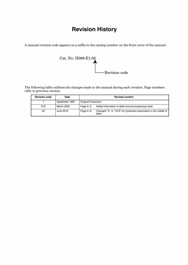
E5AK
Revision History
A manual revision code appears as a suffix to the catalog number on the front cover of the manual.
Cat. No. H088-E1-02
Revision code
The following table outlines the changes made to the manual during each revision. Page numbersrefer to previous version.
Revision code Date Revised content
1 September 1997 Original Production
01A March 2005 Page A--3: Added information to table and accompanying notes
02 June 2010 Page A--9: Changed ”%” or ”%FS” for hysteresis parameters in the middle oftable.

Authorized Distributor:
In the interest of product improvement, specifications are subject to change without notice.
Cat. No. H088-E1-02Printed in Japan
0610
© OMRON Corporation 2010 All Rights Reserved.
OMRON Corporation Industrial Automation Company
OMRON ELECTRONICS LLCOne Commerce Drive Schaumburg,IL 60173-5302 U.S.A.Tel: (1) 847-843-7900/Fax: (1) 847-843-7787
Regional HeadquartersOMRON EUROPE B.V.Wegalaan 67-69-2132 JD HoofddorpThe NetherlandsTel: (31)2356-81-300/Fax: (31)2356-81-388
Contact: www.ia.omron.comTokyo, JAPAN
OMRON ASIA PACIFIC PTE. LTD.No. 438A Alexandra Road # 05-05/08 (Lobby 2), Alexandra Technopark, Singapore 119967Tel: (65) 6835-3011/Fax: (65) 6835-2711
OMRON (CHINA) CO., LTD.Room 2211, Bank of China Tower, 200 Yin Cheng Zhong Road, PuDong New Area, Shanghai, 200120, ChinaTel: (86) 21-5037-2222/Fax: (86) 21-5037-2200