e10 lvds h.264 encoder - auvidea · the models c3 and c4 feature an rs232 level ... - secondary...
TRANSCRIPT

VERSION 1.3 E10 (38117-3)
E10 LVDS H.264 encoder for block cameras
Version 1.3
Preliminary December 2016
Auvidea GmbH Kellerberg 3
D-86920 Denklingen
Tel: +49 8243 7714 622 [email protected] www.auvidea.com
AUVIDEA GMBH TECHNICAL REFERENCE MANUAL 1

VERSION 1.3 E10 (38117-3)
Copyright Notice
© Auvidea GmbH 2016
All Rights Reserved
No part of this document or any of its contents may be reproduced, copied, modified or adapted, without the prior written consent of the author, unless otherwise indicated for stand-alone materials.
You may share this document by any of the following means: this PDF file may be distributed freely, as long as no changes or modifications to the document are made.
For any other mode of sharing, please contact the author at the email below. [email protected]
Commercial use and distribution of the contents of this document is not allowed without express and prior written consent of Auvidea GmbH.
AUVIDEA GMBH TECHNICAL REFERENCE MANUAL 2

VERSION 1.3 E10 (38117-3)
Features Technical details
• H.264 video encoder • RTSP live stream • recording .mp4 file to SD card (USB device optional) • 10/100 Ethernet to connect to IP network (live stream and control) • 30 pin LVDS interface to the block camera • control of camera via HTTP request API (locally converted to RS232) • optional: HDMI out, DVI out, PoE, USB 2.0, WiFi • optional: transmuxing to other streaming protocols with WiFi option (Carambola 2 module)
Audio and video encoding
• H.264 codec up to level 4.1 (baseline, main, and high profiles) • video encoding up to 720p50/60, 1080i50/60 or 1080p24/25/30 • max. pixel clock: 74.25MHz • streaming: RTSP stream (128 to 20000 kbit/s) • live change of bandwidth, GOP size and resolution while streaming • power: 7 - 17V, 3.5W - power is connected via an add-on board, which is required (please see the list below) • size: 49 x 59 mm (fits on the back of standard size block cameras) • mounting: four 2.6mm mounting holes for M2.5 screws - extra 7mm mounting hole • weight: 17 grams (just the E10 encoding module)
Add-on modules
The E10 encoding module requires an non-optional add-on module to connect to power and network.
• 38136 Multi-IO add-on module: to connect to power, Ethernet and servos • 38139 Carambola 2 add-on module: openWRT based Wifi router, power, optional Ethernet
Software
• Linux based • control via integrated web interface • HTTP request based API (low latency: 100ms typical) • RTSP video streaming (low latency with selected players) • full access to system, video and encoding parameters
Models
E10-12
standard model - the E10 module is powered by 7V to 17V (12 typical). This voltage is directly supplied to the camera connected via the 30 pin micro coax cable.
E10-5
5V model - the E12 produces a regulated 5V for the camera, independent of the voltage which is supplied to the E10-5 (7V to 17V).
AUVIDEA GMBH TECHNICAL REFERENCE MANUAL 3

VERSION 1.3 E10 (38117-3)
Cameras tested
Please note, that the E10 encoder does not support 1080p50 and 1080p60 modes as these have a pixel clock of 148.5MHz. The E10 only supports the 74.25MHz modes which are listed above. The camera models below have been explicitly tested. However the E10 should work with any block camera which has the 30 pin micro coax (LVDS) cable connector (KEL). Please make sure, that you use the right cable. All cameras below require the same cable. It is the "1 to N" kind. If you put this cable flat on a surface with all cable in parallel, the golden contacts of both connectors should face upwards. Pin 1 is connected to pin 30. Do not use a cable, where the contacts one side face up and one side face down.
• Panasonic GP-MH330-2S (E10-12): standard size block camera with 30x zoom • Sony FCB-SE600 (E10-5): compact size with 3x zoom with 90° wide angle • Sony FCB-EV7300 (E10-12): standard size block camera • Tamron MP1010M-VC (E10-12): compact size with 10x zoom and optical stabilization
AUVIDEA GMBH TECHNICAL REFERENCE MANUAL 4
VERSION 1.3 E10 (38117-3)
Getting started Starting up the E10
1. First connect the block camera to the E10. Make sure that you use the right micro coax cable. There are 2 types. 1-1 and 1-N. The E10 requires the 1-N type to connect to standard block cameras.
2. Connect the add.on module of the E10 to the network. Connect a 12V power source to the add-on of the E10. The red LED will light up dim red.
3. Wait 2 min for the E10 to boot up. The red LED will then change to bright red.
4. Change your host system to the IP subnet 192.168.0.xxx. Open a web browser and enter address: 192.168.0.160. This is the default address of the E10.
5. Open the Admin tab, select Settings/Communication. Set the UART settings (see section below for details). Next open settings/camera. Most camera are now automatically detected. If your camera is not detected, please verify the communications settings and the cabling to the camera. If your camera is not in the list of camera models tested, please try to connect to the camera manually with API commands.
6. Set the encoder settings specify to your camera model and resolution. Please see section below for details. Make sure that audio is set to analog, as the block camera do not support audio.
7. Go to the control tab and start encoding by pressing Stream „start“. Within 10 seconds there should be a response confirmation that the stream started successfully.
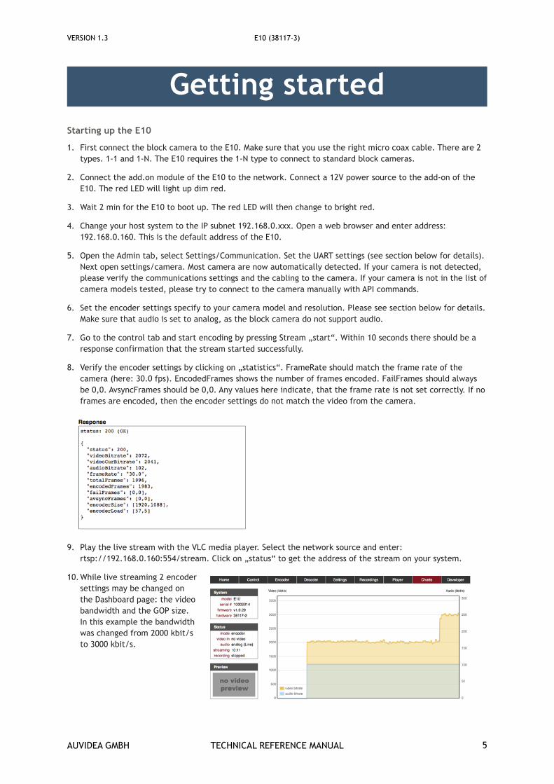
8. Verify the encoder settings by clicking on „statistics“. FrameRate should match the frame rate of the camera (here: 30.0 fps). EncodedFrames shows the number of frames encoded. FailFrames should always be 0,0. AvsyncFrames should be 0,0. Any values here indicate, that the frame rate is not set correctly. If no frames are encoded, then the encoder settings do not match the video from the camera.
9. Play the live stream with the VLC media player. Select the network source and enter: rtsp://192.168.0.160:554/stream. Click on „status“ to get the address of the stream on your system.
10.While live streaming 2 encoder settings may be changed on the Dashboard page: the video bandwidth and the GOP size. In this example the bandwidth was changed from 2000 kbit/s to 3000 kbit/s.
AUVIDEA GMBH TECHNICAL REFERENCE MANUAL 5

VERSION 1.3 E10 (38117-3)
Maintenance Integrated web server
The E10 is based on an embedded Linux system which controls the hardware H.264 HD video encoder and provides a Web GUI for control of the encoder and the camera.
HTTP request API
All encoder and camera control is performed through the http request based API. These API calls may be issued from the web based GUI, which can be also viewed as an example. Next the Developer/API page may be used to issue API commands manually. The HTTP Requestor plugin to the Firefox browser may be used to issue HTTP requests. Also these API requests may be issued from high level programming languages like PERL or Python.
Sample web pages
The web pages included with the E10 may be viewed as sample web pages. They are located in the /data/www directory. Please log in with an SSH console (user: root, password: auvidea). Changes may be made with the build-in nano editor or by editing them externally. Files may be moved to the E10 via FTP and the /home/ftp directory. Please use the FTP client FileZilla (user: ftp, password: ftp, port: 21) to exchange files. The sample files are based or http and JavaScript.
Firmware upgrade
Normally the E1xx encoder are upgraded via USB. But the E10 has no USB port. So it uses an alternative upgrade method. Please copy the unzipped upgrade file via FTP to the E10. Perform the upgrade in Settings/System by selecting „ftp“ as source (so it takes the file from the /home/ftp directory) and specify the name of the upgrade file. Click on upgrade and wait until the upgrade completion is confirmed in the Response window. This may take a couple of minutes. To free up the space on the internal Flash, please use FileZilla to erase the upgrade file. Power down and up the system (cold restart).
AUVIDEA GMBH TECHNICAL REFERENCE MANUAL 6

VERSION 1.3 E10 (38117-3)
Camera control Configuration of UART 2
The UART 2 of the E10 is connected to the block camera via the 30 pin micro coax cable. Please set the UART parameters according to the requirements of the camera.
A Sony block camera should be set to 9600 baud, unless the setting in the camera has been changed. Please check the „save“ box before applying any changes, so that the setting is saved permanently.
Open Settings/Camera to connect to the camera. If the communications settings are set correctly the camera will be detected automatically.
AUVIDEA GMBH TECHNICAL REFERENCE MANUAL 7

VERSION 1.3 E10 (38117-3)
Click on any of the buttons, to send an http request API command to the camera.
Example:
Command „Tele“ send the following post API request. The command is send as VISCA command. The hex values are translated to decimal numbers. E.g. 0x81 becomes 129 and 0xFF becomes 255.
URL: http://192.168.0.160/api/rs232
Post message: mode=sony&data=129,1,4,7,32,255
Feel free to test any custom VISCA command with the Developer/API page.
AUVIDEA GMBH TECHNICAL REFERENCE MANUAL 8

VERSION 1.3 E10 (38117-3)
Sample encoder settings 1080p25 (Tamron block camera)
1080p30 (Sony FCB-EV7300 block camera)
AUVIDEA GMBH TECHNICAL REFERENCE MANUAL 9

VERSION 1.3 E10 (38117-3)
38136-2 add-on The 38136-2 Multi I/O add-on module is the new version of the 38136. The 38136 is no longer being produced. 38136-2 is the version of the PCB. It is available in 4 variants, which are shown below:
Exx-IO-C4 Exx-IO-C3 Exx-IO-C2 Exx-IO-C1
UART with TTL level
These are the TTL (3.3V level UART) signals straight from the MG3500 processor. They may be used to be routed to the TTL UART of a micro controller or a USB to TTL converter. The TTL UART signals are just available on the 2 models C1 and C2. Please connect to the 3 pins on the top right of the 12 pin header.
RS232 UART with level converter
The models C3 and C4 feature an RS232 level converter. Here the 4 connector on the lower right and the 16 pin level converter chip is populated.
Model SKU UART 100BT Description
Exx-IO-C1 38230 TTL level
RJ45 jack
multi I/O add-on for the compact encoders: E10/E12/E20 (RJ45 jack for 100BT Ethernet, TTL UART - 3.3V)
Exx-IO-C2 38231 TTL level
1.25mm connector
multi I/O add-on for the compact encoders: E10/E12/E20 (without RJ45 jack - for direct Ethernet cable connection, TTL UART - 3.3V)
Exx-IO-C3 38232 RS232 level
RJ45 jack
multi I/O add-on for the compact encoders: E10/E12/E20 (RJ45 jack for 100BT Ethernet, UART with RS232 level converter)
Exx-IO-C4 38233 RS232 level
1.25mm connector
multi I/O add-on for the compact encoders: E10/E12/E20 (without RJ45 jack - for direct Ethernet cable connection, UART with RS232 level converter)
Exx-C2 38139 TTL level
1.25mm connector
Carambola2 add-on module for the compact encoders - 2.4GHz Wifi - secondary processor for stream post processing and transmuxing
AUVIDEA GMBH TECHNICAL REFERENCE MANUAL 10
VERSION 1.3 E10 (38117-3)
12V power connector (J2)
Main power connector to power the 38136-2 and the E10/E12/E20. This is a 4 pin connector with 1.25mm pitch. Auvidea does supply a cable kit. Molex part number of the 4 pin terminal housing: 0510210400. Auvidea can provide cable kits with pre-crimped cables.
Ethernet connector On two models the RJ45 Ethernet jack is replaced by a 4 pin connector with 1.25mm pitch. This allows to connect the Ethernet cable with a space saving connector. Molex part number of the 4 pin terminal housing: 0510210400.
USB 2.0 connector (J6)
By default this modules are not populated with an USB 2.0 port. This may be added by populating a standard USB type a jack. The USB 2.0 port is then connected to the MG3500 and may be used for firmware upgrade or data storage.
RS232 connector (J8)
On two models the RS232 level converter and a 4 pin connector with 1.25mm pitch is populated. This allows connection to peripheral devices with RS232 interface. Pin 1 is located on the bottom (in the pictures above). Molex part number of the 4 pin terminal housing: 0510210400.
Pin Function Jetson TX1 Description
1,2 +12V F14 positive 12V supply (pin 1 is located on top in the pictures above)
3,4 GND F13 negative supply (ground)
Pin Function Description
1 TX+ 100BT Ethernet (Transmit +)
2 TX- 100BT Ethernet (Transmit -)
3 RX+ 100BT Ethernet (Receive +)
4 RX- 100BT Ethernet (Receive -)
Pin Function Description
1 5V 5V power output (do not put in power)
2 D- Data signal -
3 D+ Data signal +
4 GND Ground
Pin Function Description
1 5V 5V power output (do not put in power) (pin 1 is marked)
2 RS232_TxD Transmit data of ttyS1 port of MG3500
3 RS232_RxD Receive data of ttyS1 port of MG3500
4 GND Ground
AUVIDEA GMBH TECHNICAL REFERENCE MANUAL 11

VERSION 1.3 E10 (38117-3)
Servo connector (J1)
All models have the 12 pin 2.54mm header with the 3 servo ports and the UART TTL signals. The pins are arranged in the way that the standard 3 pin servo connectors may be directly plugged in. 2 servos on the left side, 1 servo on the right side (bottom). GND should face down. To enable servo mode please issue the post API command:
http://192.168.0.161/api/pwmaction=save&pwmOn=1
Multi I/O module version C1 (12 pin header annotated)
The label underneath the 12 pin header reads: “RS232 + servo”. This is a little misleading, as the pin header carries the TTL UART signals (C1 and C2) and not the RS232 level signals. On the C3 and C4 the UART pins (2 and 2) of this 12 pin header are not connected. These signals are routed to the RS232 level converter instead.
Pin Function Description
1 Servo_3 Servo_3 signal (5V - active low)
2 UART_RxD Receive data of ttyS1 port of MG3500 (TTL level - only C1 and C2)
3 5V 5V power out for servo 3
4 UART_TxD Transmit data of ttyS1 port of MG3500 (TTL level - only C1 and C2)
5 GND GND for Servo 3
6 GND GND for UART port
7 Servo_1 Servo_1 signal (5V - active low)
8 Servo_2 Servo_2 signal (5V - active low)
9 5V 5V power out for servo 1
10 5V 5V power out for servo 2
11 GND GND for servo 1
12 GND GND for servo 2
AUVIDEA GMBH TECHNICAL REFERENCE MANUAL 12

VERSION 1.3 E10 (38117-3)
38136 add-on (old version)
Multi I/O add-on module (38136)
The 38136 is a half sized card to bring out some of the key interfaces like Ethernet, a power connector, the PWM signals and optionally space for a USB connector.
The RJ45 connector is optional. For space saving applications the Ethernet cable may be directly soldered to the 38136 module.
J2: 2.54mm 2 pin header
J9: 2 pin connector (cable: TE 2058943-1)
AUVIDEA GMBH TECHNICAL REFERENCE MANUAL 13

VERSION 1.3 E10 (38117-3)
For special requirements a custom version of this interface board could be designed. Please contact Auvidea.
AUVIDEA GMBH TECHNICAL REFERENCE MANUAL 14

VERSION 1.3 E10 (38117-3)
38139 wifi add-on As an alternative to the 38136 Multi I/O module, the 38139 Wifi add-on module may be plugged on top of the E10. It adds router, Wifi and post processing features.
• Carambola 2 based add-on module for the E10/E12/E20 • 400 MHz MIPS processor (Artheros 9331) with 64MB RAM and 16MB Flash • openWRT based (special Linux version for routers) • extensive network management features for Wifi, NAT and port forwarding • 2 10/100 Ethernet ports - one internally connected to the encoder (LAN port) and one externally available (LAN port) • integrated 2.4 GHz Wifi • optional 5.8 GHz Wifi with USB stick or optional 3G/4G modem (via USB connector) • space saving embedded style design with external connectors or direct cable connections
Transmuxing of the RTSP video stream
ffmpeg may be installed on this module to receive the RTSP (or UDP) stream from the E10/E12/E20, and transmux it into a different streaming format like RTMP. No transcoding is performed, as the processor is not powerful enough to decide the video and encode it again. By transmuxing the compressed video packets are not touched. Just the encapsulating protocol is changed.
AUVIDEA GMBH TECHNICAL REFERENCE MANUAL 15

VERSION 1.3 E10 (38117-3)
Connectors of on the 38139 module
• J1: USB port of the encoder • J2: UART 1 port of the encoder (3.3V TTL level) This may be controlled through the http request API of the encoder to control PTZ cameras • J3: 12 pin header (2.54 mm) for 3 servos controlled by the encoder and 3 pins pins for UART (console) port of the Carambola 2 • J4: 12V power supply input (the center pin is not used) - 3 pin 1.25mm pitch • J7: USB port of the Carambola module (the footprint supports soldering of a standard USB connector) • J6: 3 pin 1.25 mm pitch connector for 10/100 WAN port (RX) - may connect to Ethernet cable or passive RJ45 connector • J8: 3 pin 1.25 mm pitch connector for 10/100 WAN port (RX)
Extending the Flash
The Carambola 2 only has 16 MByte of Flash memory. A standard compilation of ffmpeg takes about 40 MByte of disk space. The program memory of the Carambola 2 may be extended by mounting a part of the Flash memory of the E10/E12/E20 encoder with davfs. This is basically a disk mount using the http protocol. Please see the W100 users guide for more information.
AUVIDEA GMBH TECHNICAL REFERENCE MANUAL 16

VERSION 1.3 E10 (38117-3)
38138 mounting plate The E10 encoder may b
AUVIDEA GMBH TECHNICAL REFERENCE MANUAL 17

VERSION 1.3 E10 (38117-3)
Connectors Auvidea supplies cable kits for the c
Figure 1: connectors on the top side
Figure 2: connectors on the bottom side
AUVIDEA GMBH TECHNICAL REFERENCE MANUAL 18

VERSION 1.3 E10 (38117-3)
Expansion connector (J2)
This is a 40 pin DF12 male connector (DF12-40DS-0.5V(86)).
Pin Function Voltage Description
1 PWFB_OUT - center voltage output for Ethernet magnetics
2 USB-D- - USB 2.0 data
3 TPTX- - 100BT Ethernet transmit output
4 USB-D+ - USB 2.0 data
5 TPTX+ - 100BT Ethernet transmit output
6 V_USB 5V USB bus voltage input (for monitoring)
7 GND 0V Ground
8 LED_0 3.3V Ethernet LED 0
9 PWM_0 3.3V PWM 0 output, to control LED or servo
10 LED_1 3.3V Ethernet LED 1
11 PWM_1 3.3V PWM 1 output, to control LED or servo
12 SCL_0 3.3V I2C 0 clock (MG3500 is master)
13 PWM_2 3.3V PWM 2 output, to control LED or servo
14 GPIO_1_25 3.3V Reset output
15 GND 0V Ground
16 UART1_TXD 3.3V UART 0 transmit data output
17 TPRX- - 100BT Ethernet receive input
18 SDA_0 3.3V I2C 0 data
19 TPRX- - 100BT Ethernet receive input
20 UART1_RXD 3.3V UART 0 receive data input
21 GND 0V Ground
22 UART0_TXD 3.3V UART 2 transmit data output (debug console)
23 Enable_1.05V O.D. Pull low, to turn off E10, float: E10 is powered up
24 UART0_RXD 3.3V UART 2 receive data input (debug console)
25 Power in 12V Main power input to E10 (range: 7V to 17V)
26 CFG 1.8V Pull to 1.8V for low level firmware flash (do not connect)
27 Power in 12V Main power input to E10 (range: 7V to 17V)
28 GPIO_0 3.3V GPIO_0 input/output
29 5V 5V 5V regulated output
30 RESET_CPU 3.3V Reset input to reset MG3500 CPU - low active)
31 5V 5V 5V regulated output
32 A_DATA 3.3V I2S digital audio input
33 1.8V 1.8V 1.8V regulated output
Pin
AUVIDEA GMBH TECHNICAL REFERENCE MANUAL 19

VERSION 1.3 E10 (38117-3)
If you would like to use the I2S digital audio bus, please contact Auvidea for further details.
External SD card connector (J1)
This is a 16 pin FPC connector, to connect to an external SD card reader (connector: HFW16R-2STE1LF). The signals are connected in parallel to the micro SD card reader (J4) on the bottom side of the E10. Please only use the internal or external card reader at a time.
34 A_MCLK 3.3V I2S digital audio master clock input/output (256 fs)
35 SCL_2 3.3V I2C 2 clock (MG3500 is master)
36 A_BCK 3.3V I2S digital audio bit clock input/output
37 SDA_2 3.3V I2C 2 data (MG3500 is master)
38 A_LRCLK 3.3V I2S digital audio word clock input/output
39 3.3V 3.3V 3.3V regulated output
40 A_ODATA 3.3V I2S digital audio data output
Function Voltage DescriptionPin
Pin Function Voltage Description
1 3.3V 3.3V 3.3V power supply
2 S_D2 3.3V SD data D2
3 GND 0V Ground
4 S_D3 3.3V SD data D3
5 GND 0V Ground
6 S_CMD 3.3V SD command
7 GND 0V Ground
8 S_CLK 3.3V SD clock
9 GND 0V Ground
10 S_D0 3.3V SD data D0
11 GND 0V Ground
12 S_D1 3.3V SD data D1
13 GND 0V Ground
14 S_CD 3.3V SD change disk
15 S_WP 3.3V SD write protect
16 GND 0V Ground
AUVIDEA GMBH TECHNICAL REFERENCE MANUAL 20

VERSION 1.3 E10 (38117-3)
LVDS camera connector (J5)
This is a 30 pin KEL micro coax connector (KEL-USL00-30L-C). Do not use block cameras, where the second LVDS bus is enabled, as this bus will be shorted (pins 7 to 10 are connected to GND). The next revision of the E10 will have pins 7 to 10 floating to avoid a short. This applies to Sony block cameras (7300 to 7500). Please use these cameras in single LVDS mode only.
Pin Function Voltage Description
1 Pr - not connected
2 Pb - not connected
3 Y - not connected
4 VBS - not connected
5 RESET_CPU 3.3V not connected
6 - - -
7 GND 0V Ground (2nd LVDS bus)
8 GND 0V Ground (2nd LVDS bus)
9 GND 0V Ground (2nd LVDS bus)
10 GND 0V Ground (2nd LVDS bus)
11 GND 0V Ground
12 GND 0V Ground
13 Power 5V/12V 5V regulated (E10-5) or 12V unregulated (E10-12)
14 Power 5V/12V 5V regulated (E10-5) or 12V unregulated (E10-12)
15 Power 5V/12V 5V regulated (E10-5) or 12V unregulated (E10-12)
16 Power 5V/12V 5V regulated (E10-5) or 12V unregulated (E10-12)
17 Power 5V/12V 5V regulated (E10-5) or 12V unregulated (E10-12)
18 UART2_TXD 3.3V connects to RXD of camera
19 UART2_RXD 5V connects to TXD of camera (5V tolerant)
20 GND 0V Ground
21 RA_N - LVDS channel A
22 RA_P - LVDS channel A
23 RB_N - LVDS channel B
24 RB_P - LVDS channel B
25 RC_N - LVDS channel C
26 RC_P - LVDS channel C
27 CLK_N - LVDS channel clock
28 CLK_P - LVDS channel clock
29 RD_N - LVDS channel D
30 RD_P - LVDS channel D
AUVIDEA GMBH TECHNICAL REFERENCE MANUAL 21

VERSION 1.3 E10 (38117-3)
FAQ 1. Control camera UART from an external device or system:
If you like to disconnect the MG3500 UART port from the camera UART interface, please follow the following steps. Please note, that these modifications void the warranty of the E10.First remove 2 resistors. The top is a 0603 size 470 Ohm resistor (R4) to connect the TxD of the MG3500 to the camera. By removing this resistor the MG3500 is disconnected and an TxD signal from an external controller (3.3V or 5V) may be soldered to the right pad. This is the pad the bubble arrow points to.The bottom resistor is 0402 size and has 0 Ohm (R1). Please remove this resistor and connect the right pad to the RxD (5V) of your system. Please note that the camera provides a 5V RxD signal (TxD of the camera). RxD and TxD are swapped. If you decide to replace, please make sure that you install a 470 Ohm resistor, to reduce the RxD voltage from 5V to 3.3V for the MG3500.
AUVIDEA GMBH TECHNICAL REFERENCE MANUAL 22
VERSION 1.3 E10 (38117-3)
Disclaimer Thank you for reading this manual. If you have found any typos or errors in this document, please let us know.
This is the preliminary version of this data sheet. Please treat all specifications with caution as there may be any typos or errors.
The Auvidea Team
AUVIDEA GMBH TECHNICAL REFERENCE MANUAL 23