e-series screw jacks - statewide bearings · ball nut design ... that do not conflict with another...
TRANSCRIPT

Metric Machine Screw Jack
Metric Ball Screw Jack
Stainless Steel Machine Screw Jack
E-SeriesScrew Jacks

E-Series
1
BEST ENGINEERED SOLUTION FOR PRECISION LINEAR ACTUATION, POWER TRANSMISSION & MECHANICAL JACKING.

13www.powerjacks.com
DESIGN WITH POWER
Complimenting the screw jacks, the Power Jacks portfolio also includes the design and manufacture of spiral bevel gearboxes, electric linear actuators and planetary roller screws. This enables us to offer our customers a complete linear motion and power transmission system and solution.
We know our customers demand our engineering expertise to help find a solution for their applications. We take pride in designing and delivering the best solution.
This is what defines the Power Jacks range.
Our expertise has been built on a history of engineering craftsmanship and design dating back to 1903. The facility in Scotland is the UK’s largest screw jack manufacturing facility, that uses the latest engineering technologies to deliver quality products (BS EN ISO 9001:2008) that offer reliability, performance and economy.
Power Jacks is synonymous with screw jack technology and its development. We have been involved with screw jacks since the product was invented in the late 1930’s and this gives us unparalleled experience in the design and manufacture of both standard and special designs.
E-Series
The Company

4
E-Series
www.powerjacks.com

5www.powerjacks.com
E-Series
Index
1. E-Series Screw Jack Overview
Building System - Rotating Screw Jack .............................................6
Building System - Translating Screw Jack ........................................7
Jacking Systems ................................................................................8
Product Code ....................................................................................10
Selecting a Screw Jack .....................................................................12
2. Metric Machine Screw Jack ..................................................... 16
Features ............................................................................................18
Application Focus ..............................................................................20
Performance ....................................................................................21
Translating Screw Jack Dimensions ................................................22
Rotating Screw Jack Dimensions .....................................................24
Anti-Backlash Feature .....................................................................25
Anti-Rotation (Keyed) .......................................................................26
Secondary Guide ...............................................................................26
Safety Nuts ........................................................................................27
Double Clevis Screw Jacks ...............................................................28
Flange Bolt for Worm Shafts ............................................................29
3. Stainless Steel Machine Screw Jack ....................................... 30
Features ...........................................................................................32
Application Focus ..............................................................................34
Performance ....................................................................................35
4. Metric Ball Screw Jack ............................................................. 36
Features ...........................................................................................38
Aplication Focus ................................................................................40
Performance .....................................................................................41
Translating Screw Jack Dimensions ................................................42
Rotating Screw Jack Dimensions .....................................................44
Ball Nut Design ................................................................................45
Flange Bolt for Worm Shafts ............................................................46
Double Clevis Ball Screw Jacks .......................................................46
Anti-Rotation .....................................................................................47
5. Special Designs ........................................................................ 48
Roller Screw Jacks ...........................................................................50
Custom Features...............................................................................51
Application Focus ..............................................................................52
6. Screw Jack Accessories ........................................................... 54
End Fittings .......................................................................................56
Machine Screw Jack Bellow Boots ...................................................58
Ball Screw Jack Bellows Boots ........................................................61
Limit Switches on Cover Pipe ...........................................................64
Rotary Limit Switch - RLS ................................................................65
Rotary Limit Switch - SKA ................................................................66
Motor Adapter ...................................................................................67
Trunnion Mounts ...............................................................................68
Stop Nuts & Hand Wheels ................................................................69
7. Engineering Guide ................................................................... 70

6 www.powerjacks.com
1 E-Series - Screw Jack Overview
Building System - Rotating Screw Jack
Drive Shaft Gearbox
Motor Adapter
Double Hub Nut
Safety NutSafety Nut
Double Hub
Bellows Boot
Rotary Limit Switch Adapter
Rotary Limit Switch
Brake
Hand Wheel
Protection Cap
Encoder
Standard Nut
Electric Motor with or without:• Brake• Encoder• Forced Ventilation
Lead Screw Options:1. Standard 1 x Pitch2. 2 x Pitch3. No Pilot End4. Stainless Steel5. Left Hand Thread6. Larger Diameter Screw
Coupling
Trunnion Feet
Trunnion
1
23
45
6
Upright Inverted

7www.powerjacks.com
1E-Series - Screw Jack Overview
Building System - Translating Screw Jack
Inverted
Stop Nut
Secondary Guide
Anti-Rotation Key Adapter*
Drive ShaftGearbox
Motor Adapter
Rod End
Clevis End
Top Plate
Bellows Boot
Rotary Limit Switch Adapter
Rotary Limit Switch
Brake
Hand Wheel
Protection Cap
Encoder
Fork End
Electric Motor with or without:• Brake• Encoder• Forced Ventilation
Lead Screw Options:1. Standard 1 x Pitch2. 2 x Pitch3. Anti-Rotation (Keyed)4. Stainless Steel5. Left Hand Thread
Coupling
Limit Switches
Trunnion Feet
Trunnion
12
34
5
* For use with Anti-Backlash and some Safety Nut models only.
Upright
Available as:1. Standard2. Anti-Rotation (Keyed)3. Anti-Backlash4. Safety Nut

8 www.powerjacks.com
1 E-Series - Screw Jack Overview
Jacking Systems
Screw jacks can be connected together in systems so that multiple units can be operated and controlled together. These jacking system arrangements or configurations can be built in many formats with the use of bevel gearboxes, motors, reduction gearboxes, drive shafts, couplings, plummer blocks and motion control devices.
Four of the most popular system configurations are the ‘H’, ‘U’, ‘T’ and ‘I’ configured jacking systems. Note that multiple screw jacks can be linked together mechanically or electrically. The latter is useful if there is no space for linking drive shafts.
Typical ‘H’ configuration System
5 6
2
1
4 3
1. Screw Jack E-SeriesUpright Rotating Machine Screw Jack shown here.
2. Bevel Gearbox Neeter drive Range-N Refer to Range-N Bevel Gearbox catalogue for details.
3. Flexible Coupling A range of couplings are available to suit each systems requirements including Jaw, Spacer and Geared types.4. Drive Shaft
Every drive shaft is manufactured to order for each system design. Self supporting drive shafts (spacer couplings) are also available.5. Shaft Supports (plummer blocks).6. Electric Motor
Standard electric motors in 3phase, 1phase, DC and servo designs. Supplied as a basic motor or as part of a geared motor. Brakes are available for all motors.

9www.powerjacks.com
E-Series - Screw Jack Overview
Jacking Systems
1
‘U’ Configuration System
‘I’ Configuration System
‘T’ Configuration System
Jacking systems are not limited to the number of screw jacks shown here. They are regularly supplied to clients with 2, 4, 6, 8 jack systems. Larger systems can extend up to 16 or higher. With the use of electronic synchronisation/control multiple systems or screw jacks can be used in unison. Extending the possible number of screw jacks used in unison in excess of 100.
To facilitate electronic control of screw jacks, feedback devices (eg encoder, limit switch) are available, mounted on the screw jack or its motor or another system component.

10 www.powerjacks.com
1 E-Series - Screw Jack Overview
Product Code
Example
KME1819-300-BR, 200 kN inverted keyed translating machine screw jack with top plate, 300 mm of stroke, bellows boots fitted to protect lifting screw and a single ended worm shaft extension on the right-hand side only.
K M E 1819 300 BR
↓ ↓ ↓ ↓ ↓ ↓(a) (b) (c) (d) (e) (f)
↓ ↓ ↓ ↓ ↓ ↓Prefix Feature Series Series No. Travel of Unit (mm) Suffix
Prefix (a)
S - All Stainless Steel Screw Jack#2
K - Keyed Lifting Screw#3 (Anti Rotation)
Feature (b)
T - Threaded End on Lifting Screw (standard)M - Top Plate on End of Lifting ScrewC - Clevis End on Lifting ScrewF - Fork End on Lifting ScrewR - Rod End on Lifting ScrewP - Plain End, with no Machining on End of Lifting Screw#1
U - Upright Rotating Screw JackD - Inverted Rotating Screw JackCC - Screw Jack with Double Clevis Mounting Arrangement
Series (c)
E - E-Series Screw Jacks
Capacity and Series Designations (d)
Upright Translating Screw Jacks
Capacity (kN) 5 10 25 50 100 200 300 500 1000 1500 2000
Machine Screw Jack 2625 2501 1802 1805 1810 1820 1830 1850 18100 18150 18200
Ball Screw Jack - 28501 3802 3805 3810 3820 3830 3850 38100 38150 38200
Inverted Translating Screw JacksDecrease the upright model number by 1. Example 50kN Inverted Machine Screw Jack = 1804 200kN Inverted Ball Screw Jack = 3819
Rotating Screw JacksIncrease the upright model number by 1. Example 50kN Rotating Machine Screw Jack = 1806 200kN Rotating Ball Screw Jack = 3821
Anti-Backlash Screw JacksReplace the first digit in the model number with a 4. Example 50 kN upright anti-backlash Screw Jack = 4805

11www.powerjacks.com
1E-Series - Screw Jack Overview
Product Code
Optional Lead (Ball Screw Jacks Only)Metric Ball Screw Jacks have an increased lead screw option for the ball screw assembly (typically double). To specify the higher option add a “1” to the end of the model number.
Example 200kN Upright Ball Screw Jack with 20mm lead = E38201
Third Space Numerals (e)
The characters appearing in this space are to indicate stroke in millimetres on all standard units, but not on specials. This space on special screw jacks helps to identify to our Engineering Department the actual Screw Jack model produced. The numerals do not indicate stroke or type of modification performed on special orders.
Suffix (f)
1 - Gear ratio option-2 requiredB - Indicates bellows boot required to protect lifting screwG - Secondary guide for the lifting screwH - Stop Nut (Full Power) on Lifting ScrewL - Single-end worm shaft extension on left-hand side onlyR - Single-end worm shaft extension on right-hand side onlyD - Safety Nut Load in TensionC - Safety Nut Load in CompressionT - TrunnionX - Supplied without bottom pipe, but with guide bushingS - Special design features. More detail supplied separately. Only used at enquiry stage. Once ordered all special designs receive
a unique part number.
Note1. All suffixes (f) that do not conflict with another may be used in series against one Screw Jack2. For E-Series Screw Jacks with plain ended lifting screws consult Power Jacks3. For Stainless Steel Screw Jacks with varying materials and/or platings consult Power Jacks4. For external keyed guides consult Power Jacks.

12 www.powerjacks.com
1 E-Series - Screw Jack Overview
Selecting a Screw Jack
Five Step Guide to Initial Screw Jack Selection
The following selection procedure is applicable for Machine Screw and Ball Screw Jacks.
Calculate Power and Torque Requirements
Select a screw jack from the tables with adequate load carrying capacity and note the screw jack static and dynamicefficiency for required input speed.
Step 1 - Screw Jack Input Speed
N (rpm) =
Linear Speed (mm/min) x Gear Ratio Input speed should not exceed 1800 rpm. Number of starts on lifting screw is usually 1, unless otherwise stated.
Pitch (mm) x N° of Starts on Lifting Screw
Step 2 - Operating Input Power (kW), Pin
Pin(kW) =
Load (kN) x Linear Speed (mm/min) ηd = Dynamic Screw Jack Efficiency60000 x ηd
Step 3 - Operating Input Torque
Tino (Nm) = Pin (kW) x 9550
N (rpm)
Step 4 - Screw Jack Start-Up Torque
Tins = Load (kN) x Pitch (mm) x N° of Starts on Lifting Screw ηs = Static Screw Jack Efficiency
2 x π x ηs x Gear Ratio
Step 5 - Mechanical Power and Torque Check
Check whether the screw jack power and torque required for the application is not greater than the maximum allowable mechanical input power (Pmechanical) and Start-Up Torque at Full Load (Ts) values specified in the screw jack performance tables.
If Pmechanical > Pin & Ts > Tins then the screw jack selected is acceptable for power requirements.

13www.powerjacks.com
1E-Series - Screw Jack Overview
Selecting a Screw Jack
Example Selection
Application Constraints
• Load on Screw Jack = 15 kN in Tension• Linear Speed required = 100 mm/min
Consider all application constraints then choose a screw jack that looks suitable for the application with a load rating equal to or greater than the maximum working load. For this example, a 25 kN E-Series Machine Screw Jack (refer P21) with translating screw, 6:1 gear ratio, single start lifting screw (6 mm lead).
Calculate Power and Torque Requirements
Step 1 - Screw Jack Input Speed
N (rpm) =
100 (mm/min) x 6 (Gear Ratio) N = 100 rpm Input speed should not exceed 1800 rpm.6 (mm) x 1 (N° of starts on Lifting Screw)
Step 2 - Operating Input Power (kW), Pin
Pin(kW) =
15 (kN) x 100 (mm/min) ηd = 0.264 (Refer P21) Pin = 0.095 kW60000 x 0.264
Step 3 - Operating Input Torque
Tino (Nm) =
0.095 (kW) x 9550Tino = 9.1 Nm
100 (rpm)
Step 4 - Screw Jack Start-Up Torque
Tins = 15 (kN) x 6 (mm) x 1 (N° of starts on Lifting Screw) Tins = 11.9 Nm
ηs = 0.201 (refer P21)2 x π x 0.201 x 6 (Gear Ratio)
Step 5 - Mechanical Power and Torque Check
Find the screw jacks mechanical power and torque rating from the performance data tables (refer P21).
Pmechanical = 1.5 kW > Pin and Ts = 19 Nm > Tins
Therefore the screw jack selected is suitable for application for initial constraints tested, further analysis may be required to ensure the screw jack is suitable for all application conditions. Continue with further selection calculations or consult Power Jacks Ltd.

14 www.powerjacks.com
1 E-Series - Screw Jack Overview
Selecting a Screw Jack
Screw Jack Constraints for Detailed Selection
Lifting Screw Column Strength
For compressive loads on the screw jack lifting screw column strength calculations are required to check for buckling. As a screw jack selection guide use the following process:
1. Determine the maximum column strength (L) for the screw jack being considered (refer Engineering Guide P70).2. Referring to the relevant column buckling chart (refer P72-75) determine the permissible compressive load (Wp) corresponding
to the column length (L) for the appropriate end constraints. This permissible compressive load is the maximum load (inclusive of shock loads) which may be applied to the screw jack for a given column length.
3. Where an application involves human cargo or there is a risk to personnel, it is highly recommended that the permissible compressive load (as calculated above) be factored by 0.7 to enhance working safety. (Equivalent to a column strength safety factor of 5).
Wphc
= Wp
x 0.7 (Permissible compressive load for personnel risk applications)
Note 1. For detailed analysis of screw jacks and their systems consult Power Jacks. 2. Safety factor of 3.5 for column strength’s used for normal industrial cargo.
Lifting Screw Critical Speed
For fast operating rotating screw jacks, the critical speed (rotational speed) of the lifting screw needs to be considered in case of shaft whirling. To calculate the critical speed for rotating screw jacks:
1. Refer to the appropriate critical speed chart in the Engineering Guide on P76.2. Select the correction factor F
cs corresponding to the end support conditions for the application.
3. From the critical speed chart, select the critical speed corresponding to the unsupported screw length (m) and the screw jack load rating (kN).
4. Calculate the limiting critical speed with the formula: Limiting Critical Speed = Critical screw speed x FCS
Lifting Screw Deflection
The lifting screw of a screw jack mounted horizontally will deflect under its own weight to some extent. The amount of deflection tolerable (yT
) should be less than 0.5 mm per metre.
Deflection Factors, Fsd
Fixed/Fixed. Fsd
= 8 Fixed/Fixed. Fsd
= 186 Fixed/Fixed. Fsd
= 384
LLL
Deflection, y, (mm) =6 x 10⁻⁹ x L4
Fsd (d-p)2Deflection Tolerable, yT, (mm) =
0.5 x L
1000
L = Lifting Screw Length (mm) d = Diameter of Lifting Screw (mm) p = Pitch of Lifting Screw (mm)
If y < yT then the lifting screw deflection is acceptable.
Note: This is only a deflection guide. For detailed analysis, including methods to reduce deflections, consult Power Jacks Ltd.

15www.powerjacks.com
1E-Series - Screw Jack Overview
Selecting a Screw Jack
Screw Jack Input Torque
Start up/static torque values are listed in all perfomance tables. Whereas dynamic torque values are either calculated using the tabulated dynamic efficiencies or taken direct from torque tables where listed. For detailed screw jack analysis consult Power Jacks Ltd.
Side Loads on Screw Jacks
It is recommended that all side loads (Fsl) are carried by guides in your arrangement and not by the lifting screw and nut. If there are any side loads on the screw jack, they must not exceed those tabulated in the Engineering Guide, Side Load Rating Section P78, and it must be noted that any such loads will adversely affect the life of the lifting screw and nut.
Radial Forces on Screw Jack Worm Shaft
For applications where a screw jack is belt driven, radial force (FR) values exerted on the worm shaft must not exceed those tabulated in the Engineering Guide Section P79. Values are tabulated for the metric machine screw jacks and ball screw jacks. The values are maximum values for the screw jacks at rated load regardless of worm speed or load direction.
Screw Jack Self-Locking
Approximately 50% of machine screw jacks are self-locking (Refer P83) either in the gearbox or the lifting screw, however to ensure there is no self-lowering and to reduce drift due to the motor slowing, a brake is recommended. Standard motor frame size brakes will be suitable for most applications with only slight vibration (Refer P86) and thermal fluctuation present. Motor selection as normal. For dynamic braking consult Power Jacks.
Ball screw jacks always require a brake as their high efficiency makes them self-lowering.
Use the closest standard brake size that is greater or equal to the motor brake torque required.
Note 1. Self lowering can occur in any jacking system not fitted with a brake, where high levels of vibration are present in the application. 2. Power Jacks recommend the use of a brake on single screw jack applications in the vertical postion.
Jacking System Power Input
Total Input Power for Jacking Systems (kW), Ps:
Ps = Input Power per Screw Jack (kW) x Number of Screw jacks
Arrangement Efficiency x Gearbox Efficiency
Number of Screw Jacks in System 2 3 4 6-8
Jacking System Efficiency 0.95 0.90 0.85 0.80
Gearbox Efficiency = Bevel Gearbox Efficiency x Reduction Gearbox EfficiencyBevel Gearbox Efficiency = 0.95 typicalReduction Gearbox Efficiency = Consult unit details, if no reduction gearbox present assume efficiency of 1.
Note For Screw Jacks connected in-line, the worm shaft can transmit up to 3 times the torque for a single screw jack at its maximum capacity, except the E1820 (200kN) Unit which can transmit 1.5 times the torque (refer P86).

Metric Machine Screw Jack
E-Series
2
AVAILABLE IN MANY STANDARD MODELS WITH A WIDE RANGE OF CAPABILITIES, THERE IS A STANDARD MODEL FOR ALMOST ANY REQUIREMENT.

217www.powerjacks.com
E-Series - Metric Machine Screw Jack
Key Features
Key Features
• Standard Performance Power Jack• Metric Single Face Machine Screw Jacks• Capacities - 5kN to 2000 kN as standard• Translating and Rotating Screw in Upright and Inverted types• Precision Worm Gear Set• 2 Gear ratios and 1 screw lead as standard• Anti-backlash and anti-rotation (keyed) options• 6 mounting options including trunnion and double clevis• Special custom designs available

E-Series - Metric Machine Screw Jack
Features18
2
Bellows Boot Screw Protection Prevents ingress of dirt and debris onto screw threads.
Shell Cap Locked in place by set screws.
Load Bearings Bearings, top and bottom to take loads in tension or compression.
Mounting Bolt Holes
Worm Shaft Available in standard, plated or stainless steel.
End Fittings as Standard
1. Top Plate (shown)
2. Clevis End
3. Fork End
4. Rod End
Accurately hobbed aluminium bronze worm gear for greater gear contact.
Grease Application Point
Integrated Lubrication Systems
Precision Machined Lead Screw available in standard material or stainless steel.
Threaded end on screw as standard. End fittings screw on.
Thrust Bearings and Grease SealsAt each end of worm. 5 & 10 kN models do not have separate seals.
Cover PipeProtects lifting screw threads.
Housing Aluminium on 5 & 10 kN models, ductile iron on 25 kN through 100 kN models, cast steel on 200 kN through 2000 kN models.
219www.powerjacks.com
E-Series - Metric Machine Screw Jack
Features
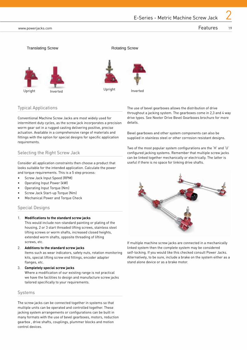
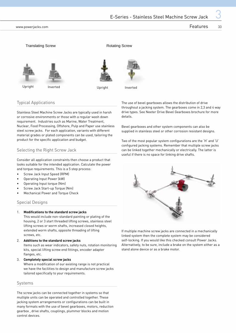
Translating Screw Rotating Screw
Typical Applications
Conventional Machine Screw Jacks are most widely used for intermittent duty cycles, as the screw jack incorporates a precision worm gear set in a rugged casting delivering positive, precise actuation. Available in a comprehensive range of materials and fittings with the option for special designs for specific application requirements.
Selecting the Right Screw Jack
Consider all application constraints then choose a product that looks suitable for the intended application. Calculate the power and torque requirements. This is a 5 step process:
• Screw Jack Input Speed (RPM)• Operating Input Power (kW)• Operating Input Torque (Nm)• Screw Jack Start-up Torque (Nm)• Mechanical Power and Torque Check
Special Designs
1. Modifications to the standard screw jacks This would include non-standard painting or plating of the housing, 2 or 3 start threaded lifting screws, stainless steel lifting screws or worm shafts, increased closed heights, extended worm shafts, opposite threading of lifting screws, etc.
2. Additions to the standard screw jacks Items such as wear indicators, safety nuts, rotation monitoring kits, special lifting screw end fittings, encoder adapter flanges, etc.
3. Completely special screw jacks Where a modification of our existing range is not practical we have the facilities to design and manufacture screw jacks tailored specifically to your requirements.
Systems
The screw jacks can be connected together in systems so that multiple units can be operated and controlled together. These jacking system arrangements or configurations can be built in many formats with the use of bevel gearboxes, motors, reduction gearbox , drive shafts, couplings, plummer blocks and motion control devices.
Inverted UprightUpright Inverted
The use of bevel gearboxes allows the distribution of drive throughout a jacking system. The gearboxes come in 2,3 and 4 way drive types. See Neeter Drive Bevel Gearboxes brochure for more details.
Bevel gearboxes and other system components can also be supplied in stainless steel or other corrosion resistant designs.
Two of the most popular system configurations are the ‘H’ and ‘U’ configured jacking systems. Remember that multiple screw jacks can be linked together mechanically or electrically. The latter is useful if there is no space for linking drive shafts.
If multiple machine screw jacks are connected in a mechanically linked system then the complete system may be considered self-locking. If you would like this checked consult Power Jacks. Alternatively, to be sure, include a brake on the system either as a stand alone device or as a brake motor.
20 www.powerjacks.com
2
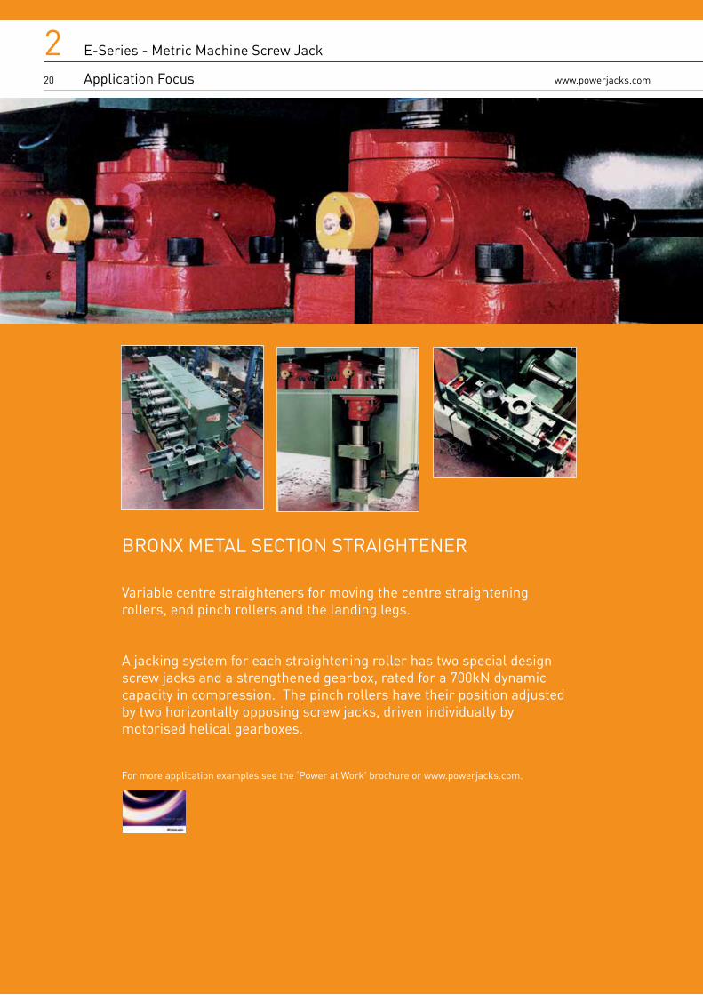
BRONX METAL SECTION STRAIGHTENER Variable centre straighteners for moving the centre straightening rollers, end pinch rollers and the landing legs.
A jacking system for each straightening roller has two special design screw jacks and a strengthened gearbox, rated for a 700kN dynamic capacity in compression. The pinch rollers have their position adjusted by two horizontally opposing screw jacks, driven individually by motorised helical gearboxes.
For more application examples see the ‘Power at Work’ brochure or www.powerjacks.com.
E-Series - Metric Machine Screw Jack
Application Focus

221www.powerjacks.com
E-Series - Metric Machine Screw Jack
Performance
Standard Performance
Model E2625 E2501 E1802 E1805 E1810 E1820 E1830 E1850 E18100 E18150 E18200
Capacity kN 5 10 25 50 100 200 300 500 1000 1500 2000
Lifting Screw note1 mm 16 x 3 20 x 5 30 x 6 40 x 9 55 x 12 65 x 12 95 x 16 120 x 16 160 x 20
Ava
ilabl
e on
Req
uest
Avai
labl
e on
Req
uest
Gear RatiosOption 1 5:1 5:1 6:1 6:1 8:1 8:1 10 2/3:1 10 2/3:1 12:1
Option 2 20:1 20:1 24:1 24:1 24:1 24:1 32:1 32:1 36:1
Turn of worm for travel of lifting
screw
Option 1 5 for 3mm
1 for 1mm
1 for 1mm
1 for 1.5mm
1 for 1.5mm
1 for 1.5mm
1 for 1.5mm
1 for 1.5mm
3 for 5mm
Option 2 20 for 3mm
4 for 1mm
4 for 1mm
4 for 1.5mm
2 for 1mm
2 for 1mm
2 for 1mm
2 for 1mm
9 for 5mm
Max. Input Power (kW)
Option 1 0.25 0.375 1.5 3 3.75 3.75 6 11.25 18.5
Option 2 0.12 0.19 0.375 0.55 1.125 1.125 1.9 4.5 8.25
Start up torque at full
load (Nm) note2
Option 1 2.5 6.8 19.8 56 115.9 263.8 480 904 2025
Option 2 1.1 3 8.7 25.5 60.5 137 284 504 1119
Weight (kg) - stroke = 150mm 1.03 2.27 8.17 15.88 24.72 45 86 195 553
Weight (kg) per extra 25mm 0.073 0.13 0.21 0.32 0.57 0.86 1.58 2.49 4.31
Opt
ion
1
Gear Ratio 5 5 6 6 8 8 10 2/3 10 2/3 12
Screw Jack Static Efficiency
0.189 0.233 0.201 0.213 0.206 0.181 0.149 0.132 0.131
Screw Jack Dynamic Efficiency
0.252 0.306 0.264 0.281 0.272 0.242 0.205 0.181 0.178
Opt
ion
2
Gear Ratio 20 20 24 24 24 24 32 32 36
Screw Jack Static Efficiency
0.107 0.130 0.115 0.117 0.132 0.116 0.084 0.079 0.079
Screw Jack Dynamic Efficiency
0.160 0.194 0.167 0.172 0.190 0.169 0.128 0.120 0.123
Notes1. All metric machine screws have a trapezoidal thread form, single start as standard (diameter x pitch)2. For loads of 25% to 100% of screw jack capacity, torque requirements are approximately proportional to the load3. Efficiency values for standard grease lubricated worm gear box and lifting screw4. All E-Series screw jacks have grease lubricated gearbox and lead screw as standard5. For performance data for Anti-Backlash, Anti-Rotation (Keyed) and other variants, see p25.

22 www.powerjacks.com
2 E-Series - Metric Machine Screw Jack
Translating Screw Jacks Dimensions
Plan View
Plan View
Plan View
Models:26252501
Note 1. Closed Height of threaded end and top plate units is the same for upright or inverted models2. LHS = Left Hand Side3. RHS = Right Hand Side.
Models: 180218051810182018301850
Models:181001815018200
ØN
W M
J
K
X
X
ØL
O
PR
Q
S
U
T
VØN
O
PR
Q
W
X
J
K
M
ØL
S
T
P R
WMØN
X
Q O
VU U
K
J
ØL
LHS
LHS
LHS
RHS
RHS
RHS

223www.powerjacks.com
E-Series - Metric Machine Screw Jack
Translating Screw Jacks Dimensions
Upright Inverted
ModelUpright E2625 E2501 E1802 E1805 E1810 E1820 E1830 E1850 E18100 E18150 E18200
Inverted E2624 E2500 E1801 E1804 E1809 E1819 E1829 E1849 E18099 E18149 E18199
Capacity (kN) 5 10 25 50 100 200 300 500 1000
Ava
ilabl
e on
Req
uest
Ava
ilabl
e on
Req
uest
A Stroke as required
B A + 9 A + 10 A + 5 A - 5 A + 3 A - 1 A + 15 A +13 A +3
C 95 125 145 185 200 265 325 390 560
C1 40 45 55 65 80 95 115 150 260
øD 16 20 30 40 55 65 95 120 160
øE 26.7 33.4 48.3 60.3 73 89 115 141 194
F 26 ± 0.13 40 ± 0.13 45 ± 0.13 60 ± 0.13 60 ± 0.13 85 ± 0.13 105 ± 0.13 120 ± 0.13 150 ± 0.13
G 10 10 13 14 16 20 30 32 40
H M10 x 1.5 M12 x 1.75
M20 x 2.5 M24 x 3 M36 x 4 M48 x 5 M72 x 4 M100 x 4 M125 x 4
I 20 24 30 35 40 55 65 90 125
J 120 150 180 230 280 300 380 460 580
K 60 75 90 115 140 150 190 230 290
øL 10 h8 14 h8 16 h8 19 h8 25 h8 28 h8 35 h8 40 h8 45 h8
M 3 x 3 x 18 5 x 5 x 25 5 x 5 x 25 6 x 6 x 32 8 x 7 x 40 8 x 7 x 40 10 x 8 x 50
12 x 8 x 56
14 x 9 x 70
øN 9 11 13.5 18 22 26 39 51 51
O 110 130 110 150 190 210 260 300 620
P 55 65 55 75 95 105 130 150 310
Q 85 100 80 115 145 150 190 200 510
R 42.5 50 40 57.5 72.5 75 95 100 255
S - - 165 205 225 275 365 535 530
T - - 65 75 75 105 140 225 205
U - - 135 170 180 215 295 435 210
V - - 50 57.5 52.5 75 105 175 150
W23.82
+ 0.076- 0.000
31.75+ 0.076- 0.000
43.26+ 0.025- 0.025
55.58+ 0.050- 0.000
66+ 0.060- 0.000
66+ 0.070- 0.000
95.25+ 0.130- 0.000
135+ 0.070- 0.000
190.5+ 0.076- 0.000
X 27 35 27.5 35 44 44 56 66 88
AA 64 90 103.5 138 146.5 195 235 275 405
BB 64 78 95.5 122 130.5 179 235 275 405
Note1. All dimensions in mm2. Closed height of threaded end and top plate units are the same for upright or inverted models3. Rotating screw jacks (refer p24) have the same dimensions for the shell as the translating screw type.

24
2www.powerjacks.com
E-Series - Metric Machine Screw Jack
Rotating Screw Jack Dimensions
E-Series - Metric Machine Screw Jack
Anti-Backlash Feature
Model UE2626 UE2502 UE1803 UE1806 UE1811 UE1821 UE1831 UE1851 UE18101 UE18151 UE18201
Capacity (kN) 5 10 25 50 100 200 300 500 1000 1500 2000
A AA + 40 AA + 44 AA + 60 AA + 80 AA + 100 AA + 100 AA + 180 AA + 200 AA + 250
Avai
labl
e on
Req
uest
Avai
labl
e on
Req
uest
B 16 16 25 30 50 65 85 100 125
C 64 90 103.5 138 146.5 195 235 275 405
D 34 0 0 0 28 24 40 63 128
øE 10 12 20 25 35 45 75 90 125
F 25 35 40 65 75 75 140 150 175
G 10 12 15 20 25 25 35 50 60
øH 60 80 90 115 160 185 230 280 380
I 4 x ø9 4 x ø11 4 x ø13.5 4 x ø18 4 x ø22 4 x ø26 6 x ø26 6 x ø33 6 x ø45
øJ 25 35 40 55 80 90 125 160 210
øK (PCD) 42 57 65 85 120 135 175 220 295
Inverted
For other dimensions and performance data refer to metric translating screw jacks. All dimensions in mm.
Model DE2626 DE2502 DE1803 DE1806 DE1811 DE1821 DE1831 DE1851 DE18101 DE18151 DE18201
Capacity (kN) 5 10 25 50 100 200 300 500 1000 1500 2000
A AA + 40 AA + 44 AA + 60 AA + 80 AA + 100 AA + 100 AA + 180 AA + 200 AA + 250
Avai
labl
e on
Req
uest
Avai
labl
e on
Req
uest
B 16 16 25 30 50 65 85 100 125
C 64 90 95.5 122 130.5 179 235 275 405
D 12 10 14 18 26.5 25 25 35 105
E 64 90 95.5 122 130.5 203 275 313 458
øF 10 12 20 25 35 45 75 90 125
G 25 35 40 65 75 75 140 150 175
H 10 12 15 20 25 25 35 50 60
øI 60 80 90 115 160 185 230 280 380
J 4 x 9 4 x 11 4 x 13.5 4 x 18 4 x 22 4 x 26 6 x 26 6 x 33 6 x 45
øK 25 35 40 55 80 90 125 160 210
øL (PCD) 42 57 65 85 120 135 175 220 295
PCD = Pitch Circle Diameter
Stroke
Pilot
Mounting Base
Bottom Pipe
Lifting Nut Shell
ØH
ØK
ØJØE
B
CAAA
F
D
I
G
Top Pipe
Mounting Base
Stroke
Pilot
Shell
Lifting Nut
E D
C AAA
G B
JH
ØF
ØKØL
ØI
Upright

225www.powerjacks.com
E-Series - Metric Machine Screw Jack
Anti-Backlash Feature
E-Series Metric Screw Jacks are available with anti-backlash nuts for applications where a reversal of loading from tension to compression is encountered and axial backlash is to be minimised.
Anti-Backlash Features • Reduction in the axial backlash between the screw and the
worm gear nut to a practical minimum for smoother, more precise operation and minimum wear
• Acts as a safety device, providing a dual nut load carrying unit, when the worm gear becomes worn
• Wear indicator for critical applications.
The anti-backlash feature can be maintained by adjusting the shell cap until the desired amount of backlash is achieved. To avoid binding and excessive wear, do not adjust lifting screw backlash to less than 0.025 mm.
Standard Dimensions (mm)
Anti-Backlash Keyed Anti-Backlash (with Anti-Rotation)
Model A B C D Model E F G H I J
E4625 95 20 65 Stroke + 34 KE4625 36 Stroke + 9 25 20 40 14
E4501 125 24 86 Stroke + 35 KE4501 38 Stroke + 9 30 24 45 16
E4802 145 30 103.5 Stroke + 30 KE4802 60 Stroke +30 37 30 55 19.5
E4805 185 35 138 Stroke - 5 KE4805 75 Stroke + 20 40 35 65 24
E4810 200 40 146.5 Stroke +3 KE4810 90 Stroke + 3 48 40 80 30
E4820 265 55 195 Stroke +24 KE4820 102 Stroke + 24 58 55 110 39
E4830 340 65 250 Stroke + 38 KE4830 138 Stroke + 15 73 65 115 43
E4850 415 90 295 Stroke + 55 KE4850 206 Stroke + 13 95 90 213 63
E48100 585 125 415 Stroke + 35 KE48100 264 Stroke + 3 180 125 405 145
Torque and Efficiencies for Standard Anti-Backlash Screw Jacks
Model Upright E4625 E4501 E4802 E4805 E4810 E4820 E4830 E4850 E48100
Inverted E4624 E4500 E4801 E4804 E4809 E4819 E4829 E4849 E48099
Capacity (kN) 5 10 25 50 100 200 300 500 1000
Start-up torque at full load (Nm)Standard 2.9 7.8 23.5 62 129 281 535 1003 2248
Optional 1.3 3.7 9.8 28 67 153 314 568 1245
Screw Jack Static EfficiencyStandard 0.164 0.203 0.169 0.192 0.185 0.170 0.134 0.119 0.118
Optional 0.090 0.109 0.102 0.105 0.119 0.104 0.076 0.070 0.071
Weight with Base Raise of 150mm (kg) approx. 1.48 2.72 8.62 16.78 26.12 48.6 90.5 208.6 609.8
Note: For loads from 25% to 100% of screw jack capacity, torque requirements are proportional to the load.
Note: Inverted unit closed height same as standard unit
Anti-Backlash Keyed Anti-Backlash (with Anti-Rotation)
AC
BD
C
FI
H
J
øE øE
G
Upright Inverted Upright Inverted
Shell
Shell Cap

26
2www.powerjacks.com
E-Series - Metric Machine Screw Jack
Anti-Rotation (Keyed)
(dimensions as non-keyed version. P22-23)
A keyed translating screw jack stops the screw from rotating without the need for end pinning. However the key-way in the screw will cause greater than normal wear on the internal threads of the worm gear.
Standard Keyed Dimensions for Inverted Models
Model E2624 E2500 E1801 E1804 E1809 E1819 E1829 E1849 E1899
Inverted
A 79 78 125.5 159 167.5 210 267 ** **
B AA + 9 AA + 35 AA + 30 AA + 20 AA + 3 AA -1 AA + 15 ** **
øC 35 N/A 60 75 90 102 141.5 ** **
Secondary Guide
Secondary Guiding for the screw for greater lateral rigidity aiding screw guidance and improved side load resilience.
Standard Secondary Guide Dimensions
Model Capacity (kN) E2625 E2501 E1802 E1805 E1810 E1820 E1830 E1850 E18100
UprightøA 36 38 60 70 90 100 138 155 225
B Stroke + 34 Stroke + 34 Stroke + 30 Stroke + 20 Stroke + 29 Stroke + 24 Stroke + 40 Stroke + 38 Stroke + 50
C 16 20 20 18 20 20 38 38 65
InvertedøD 36 ** 60 70 90 100 138 155 **
E Stroke + 34 Stroke + 34 Stroke + 30 Stroke + 20 Stroke + 29 Stroke + 24 Stroke + 40 Stroke + 38 **
F 16 ** 20 18 20 20 38 38 **
** Consult Power Jacks Ltd
Note: All dimensions in mm.
Upright Inverted
B
øC
A
AASTROKE
Upright Inverted
E
C
B
øD
øA
F

227www.powerjacks.com
E-Series Metric Machine Screw Jacks
Safety Nuts
Power Jacks metric machine screw jacks can be fitted with a safety nut, which provides 2 safety roles:
1. In the event of excessive wear on the nut thread the load will be transferred
from the standard nut to the safety nut. This will also provide visual wear
indication as the gap between the safety nut decreases to zero as the standard
lifting nut wears.
2. In the unlikely event of catostrophic nut thread failure, the safety nut will sustain
the load. The safety of industrial and human cargo is therefore improved.
There are several configurations for each safety nut device as they only work in one load direction. For this reason when ordering please supply a sketch of your application showing load directions.
Upright Rotating Screw
Model Number Rating (kN) A B C D E F G
UE1803 25 Stroke + 95 33.5 75 15 90 40 4 Holes - 13.5 Dia. on 65 Dia. PCD
UE1806 50 Stroke + 140 58 125 20 115 55 4 Holes - 18 Dia. on 85 Dia. PCD
UE1811 100 Stroke + 170 67 145 25 160 80 4 Holes - 22 Dia. on 120 Dia. PCD
UE1821 200 Stroke + 170 67 25 25 185 90 4 Holes - 26 Dia. on 135 Dia. PCD
Inverted Rotating Screw
Model Number Rating (kN) A B C D E F G
DE1803 25 Stroke + 95 33.5 75 15 90 40 4 Holes - 13.5 Dia. on 65 Dia. PCD
DE1806 50 Stroke + 140 58 125 20 115 55 4 Holes - 18 Dia. on 85 Dia. PCD
DE1811 100 Stroke + 170 67 145 25 160 80 4 Holes - 22 Dia. on 120 Dia. PCD
DE1821 200 Stroke + 170 67 25 25 185 90 4 Holes - 26 Dia. on 135 Dia. PCD
Note: All dimensions in millimetres.
ØE
Load
ØF
D B
G
ØE
D
ØE
G
A
C
Upright Models Inverted Models
B
Load
Load Load
A
C
B D
ØF
ØE
A A
CC
B D
ØF
G
G
ØF
Load
Load
Load
Load
Translating Screw Jacks with Safety Nuts
Translating Metric Screw Jacks with safety nuts are similar in format to the anti-backlash units. Consult Power Jacks for details.
Rotating Screw Jacks with Safety Nuts

28
2www.powerjacks.com
Note: For other performance and dimension information refer to translating screw models.
Model CCE 2625 CCE 2501 CCE 1802 CC 1805 CCE 1810 CCE 1820 CCE 1830 CCE 1850
Capacity (kN) 5 10 25 50 100 200 300 500
Style 1 1 2 2 2 2 2 2
A 150 180 213 260 352 428 492 570
B 115 145 470 210 247 313 367 440
C 35 35 43 50 105 115 125 130
D 15 20 23 30 33 40 60 75
E 26.7 33.4 48.3 60.3 73 102 141 168
F 15 20 30 35 40 50 80 110
øG 10 12 16 20 22 30 45 60
Max Stroke at Rated Load (Compression) 220 175 352 420 593 592 1338 1920
Note: All dimensions in millimetres unless otherwise stated.
Stroke + A
Stroke + CStroke
Standard Clevis øG
øE
F
DD
B
Style 1 Style 2
E-Series Metric Machine Screw Jacks
Double Clevis Screw Jacks

229www.powerjacks.com
E-Series Metric Machine Screw Jacks
Double Clevis Screw Jacks
E-Series - Metric Machine Screw Jack
Flange Bolt for Worm Shafts
Model ‘B’ Bolt PCD (mm) Bolt Information Configuration
E2625 N/A N/A N/A
E2501 N/A N/A N/A
E1802 46 M6 X 1mm Pitch, 14mm Deep A
E1805 61 M8 X 1.25mm Pitch, 22mm Deep A
E1810 70 M8 X 1.25mm Pitch, 14mm Deep A
E1820 88 M10 X 1.5mm Pitch, 14mm Deep A
E1830 107 M10 X 1.5mm Pitch, 19mm Deep A
E1850 135 M16 X 2mm Pitch, 25mm Deep A
E18100 160 M16 X 2mm Pitch, 28mm Deep B
Configuration A Configuration BB B
45 °
60 °
60 °
45 °
Metric Machine Stainless Steel Screw Jack
E-Series
3
DESIGNED FOR USE IN HARSH & CORROSIVE ENVIRONMENTS CAPACITIES - 10KN TO 1000KN AS STANDARD.
Stainless Steel Machine Screw Jack

331www.powerjacks.com
E-Series - Stainless Steel Machine Screw Jack
Key Features
Key Features• Standard Performance Power Jack
• Metric Single Face Machine Screw Jacks
• Capacities - 10kN to 1000kN as standard
• Translating and Rotating Screw in Upright and Inverted types
• Precision Worm Gear Set
• 2 Gear ratios and 1 screw lead as standard
• Anti-backlash and anti-rotation (keyed) options
• 6 mounting options including trunnion and double clevis
• Sealed gearbox design available
• Special custom designs available

32
3www.powerjacks.com
E-Series - Stainless Steel Machine Screw Jack
Features
The stainless steel screw jacks are ideal for use in harsh or corrosive environments such as marine, nuclear, water, food processing or paper making machinery, where standard materials may be inadequate.
Bellows Boot Screw Protection Prevents ingress of dirt and debris onto screw threads.
Shell Cap BS970 Stainless Steel locked in place by set screws.
Load Bearings Carbon Steel bearings, top and bottom to take loads in tension or compression .
Mounting Bolt Holes
Worm Shaft Material Available in standard, plated or stainless steel.
End Fittings as Standard
1. Top Plate (shown)
2. Clevis End
3. Fork End
4. Rod End
Accurately hobbed aluminium bronze worm gear for greater gear contact.
Grease Application Point
Precision Machined Lead Screw in BS970 Stainless Steel, threaded end as standard.
Thrust Bearings and Grease SealsAt each end of worm. 5 & 10 kN models do not have seals.
Bottom PipeBS970 Stainless Steel.Protects lifting screw threads.
Housing BS3100 Stainless Steel
Threaded end on screw as standard. End fittings screw on.
333www.powerjacks.com
E-Series - Stainless Steel Machine Screw Jack
Features
Translating Screw Rotating Screw
Inverted UprightUpright Inverted
Typical Applications
Stainless Steel Machine Screw Jacks are typically used in harsh or corrosive environments or those with a regular wash down requirement. Industries such as Marine, Water Treatment, Nuclear, Food Processing, Offshore, Pulp and Paper use stainless steel screw jacks. For each application, variants with different material grades or plated components can be used, tailoring the product for the specific application and budget.
Selecting the Right Screw Jack
Consider all application constraints then choose a product that looks suitable for the intended application. Calculate the power and torque requirements. This is a 5 step process:
• Screw Jack Input Speed (RPM)• Operating Input Power (kW)• Operating Input torque (Nm)• Screw Jack Start-up Torque (Nm)• Mechanical Power and Torque Check
Special Designs
1. Modifications to the standard screw jacks This would include non-standard painting or plating of the housing, 2 or 3 start threaded lifting screws, stainless steel lifting screws or worm shafts, increased closed heights, extended worm shafts, opposite threading of lifting screws, etc.
2. Additions to the standard screw jacks Items such as wear indicators, safety nuts, rotation monitoring kits, special lifting screw end fittings, encoder adapter flanges, etc.
3. Completely special screw jacks Where a modification of our existing range is not practical we have the facilities to design and manufacture screw jacks tailored specifically to your requirements.
Systems
The screw jacks can be connected together in systems so that multiple units can be operated and controlled together. These jacking system arrangements or configurations can be built in many formats with the use of bevel gearboxes, motors, reduction gearbox , drive shafts, couplings, plummer blocks and motion control devices.
The use of bevel gearboxes allows the distribution of drive throughout a jacking system. The gearboxes come in 2,3 and 4 way drive types. See Neeter Drive Bevel Gearboxes brochure for more details.
Bevel gearboxes and other system components can also be supplied in stainless steel or other corrosion resistant designs.
Two of the most popular system configurations are the ‘H’ and ‘U’ configured jacking systems. Remember that multiple screw jacks can be linked together mechanically or electrically. The latter is useful if there is no space for linking drive shafts.
If multiple machine screw jacks are connected in a mechanically linked system then the complete system may be considered self-locking. If you would like this checked consult Power Jacks. Alternatively, to be sure, include a brake on the system either as a stand alone device or as a brake motor.

34 www.powerjacks.com
DRUM POSTING EQUIPMENT (DPE) Dunreay cementation plant waste transfer facility.
Raise and lower drum transfer table.
Two stainless steel E-Series translating machine screw jacks type CE-1810-1805-1 connected in series by a stainless steel drive shaft and geared couplings.
For more application examples see the ‘Power at Work’ brochure or www.powerjacks.com.
E-Series - Stainless Steel Machine Screw Jack
Application Focus
3

335www.powerjacks.com
E-Series - Stainless Steel Machine Screw Jack
Performance
Stainless Steel Screw Jack Standard Performance
Model S-E2501 S-E1802 S-E1805 S-E1810 S-E1820 S-E1830 S-E1850 S-E18100
Capacity kN 10 25 50 100 200 300 500 10000
Sustaining
Capacity (kN) 1
Tension 6.6 16.5 33 66 132 200 333 666
Compression 10 25 50 100 200 300 500 1000
Operating
Capacity (kN) 2
Stainless Steel Worm Shaft 3.3 8.25 16.5 33 66 100 167 333
Plated Worm Shaft
Tension 6.6 16.5 33 66 132 200 333 666
Compression 10 25 50 100 200 300 500 1000
Lifting Screw 3Diameter (mm) 20 30 40 55 65 95 120 160
Pitch (mm) 5 6 9 12 12 16 16 20
Gear ratiosOption 1 5:1 6:1 6:1 8:1 8:1 10 2/3 10 2/3:1 12:1
Option 2 20:1 24:1 24:1 24:1 24:1 32:1 32:1 36:1
Turn of worm for travel of lifting
screw
Option 1 1 for 1mm 1 for 1mm 1 for 1.5mm
1 for 1.5mm
1 for 1.5mm
1 for 1.5mm
1 for 1.5mm 3 for 5mm
Option 2 4 for 1mm 4 for 1mm 4 for 1.5mm 2 for 1mm 2 for 1mm 2 for 1mm 2 for 2mm 9 for 5mm
Max. Input power (kW)
Option 1 0.375 1.5 3.0 3.75 3.75 6.0 11.25 18.5
Option 2 0.19 0.375 0.55 1.125 1.125 1.9 4.5 8.25
Start up torque at full load (Nm) 4
Option 1 2.3 6.5 18.5 38.2 87 160 301 675
Option 2 1.0 2.9 8.4 19.9 45 95 168 373
Weight (kg) - stroke = 150mm 2.27 8.17 15.88 24.72 45 86 195 553
Weight (kg) per extra 25mm 0.13 0.21 0.32 0.57 0.86 1.58 2.49 4.31
Opt
ion
1 Gear Ratio 5 6 6 8 8 10.66 10 2/3 12
Screw Jack Static Efficiency 0.233 0.201 0.213 0.206 0.181 0.149 0.132 0.131
Screw Jack Dynamic Efficiency
0.306 0.264 0.281 0.272 0.242 0.205 0.181 0.178
Opt
ion
2 Gear Ratio 20 24 24 24 24 32 32 36
Screw Jack Static Efficiency 0.130 0.115 0.117 0.132 0.116 0.084 0.079 0.079
Screw Jack Dynamic Efficiency
0.194 0.167 0.172 0.190 0.169 0.128 0.120 0.123
Notes
1. Sustaining capacity for tension is less than screw jack rating due to the performance of the stainless steel lifting screw. If a tension sustaining capacity is required equal to the screw jack rating consult Power Jacks Ltd.
2. Operational rating is less than sustaining rating due to the performance of stainless steel worm shafts. If a operating capacity is required equal to sustaining capacity consult Power Jacks for worm shaft options such as Chrome or Electroless-Nickel plating.
3. All metric stainless steel machine screws have a trapezoidal thread form, single start as standard.4. Based on operating capacity for loads of 25% to 100% of screw jack capacity, torque requirements are approximately proportional to
the load. 5. Efficiency values for standard grease lubricated worm gear box and lifting screw
External dimensions same as for Metric Machine Screw Jacks.

Metric Ball Screw Jack
E-Series
4
A BALL-BEARING TYPE HEAT-TREATED SCREW AND MATING NUT WITH ROLLING CONTACT REDUCES FRICTION TO A BARE MINIMUM IN CONVERTING TORQUE TO THRUST. Overall operating efficiency is as high as 70% in some models, depending on the worm gear ratio.

437www.powerjacks.com
E-Series - Metric Ball Screw Jack
Key Features
Features • Standard Performance Power Jack
• Metric Single Face Ball Screw Jacks
• Capacities - 10kN to 500 kN as standard
• Integral safety device
• Translating and Rotating Screw in Upright and Inverted types
• Precision Worm Gear Set
• 2 Gear ratios and 2 screw leads as standard
• Pre-loaded and Anti-rotation ball screw options
• 6 mounting options including trunnion and double clevis
• Special custom designs available

38
4www.powerjacks.com
E-Series - Metric Ball Screw Jack
Features
Bellows Boot Screw protection prevents ingress of dirt and debris onto screw threads.
Ball NutInternal continuous recirculation of steel balls. Threaded and secured to worm gear. Equiped with INTEGRAL SAFETY DEVICE.
Load Bearings Top and bottom to take loads in either direction.
Mounting Bolt Holes.
Worm Shaft Material Available with double or single shaft extension, fitted with key as standard.
End Fittings as Standard
1. Top Plate (shown)
2. Clevis End
3. Fork End
4. Rod End
Accurately hobbed aluminium bronze worm gear for greater gear contact.
Grease Application Point.
Ball ScrewStandard with threaded end.
End CapProtective cap for ball nut with guide for ball screw.
Thrust Bearings and Grease Seals at each end of worm.
Cover PipeProtects Lifting Screw Threads.
Housing Aluminium on 10 kN model.Ductile iron on 25 kN through 100 kN models, cast steel on 200 kN through 500 kN models.
Threaded end on screw as standard. End fittings screw on.

439www.powerjacks.com
E-Series - Metric Ball Screw Jack
Features
Upright UprightInverted
Translating Screw Rotating Screw
Typical Applications
Ball Screw Jacks are generally used when the application has a relatively high duty cycle or the input power for a given screw jack is to be minimised. The high efficiency of the ball screw & nut significantly increase the efficiency of a screw jack in comparison to a Machine Screw Jack. Due to their high efficiency they nearly always require a brake to hold position. They are used in a wide variety of applications including Automotive, Steel, Glass, Defence, Nuclear and Solar industries.
Selecting the Right Screw Jack
Consider all application constraints then choose a product that looks suitable for the intended application. Calculate the power and torque requirements. This is a 5 step process:
• Screw Jack Input Speed (RPM)• Operating Input Power (kW)• Operating Input Torque (Nm)• Screw Jack Start-up Torque (Nm)• Mechanical Power and Torque Check
Special Designs
1. Modifications to the standard screw jacks This would include non-standard painting or plating of the housing, high lead ball screws, stainless steel ball screws or worm shafts, increased closed heights, extended worm shafts, opposite threading of ball screws, etc.
2. Additions to the standard screw jacks Items such as wear indicators, safety nuts, rotation monitoring kits, special ball screw end fittings, encoder adapter flanges, etc.
3. Completely special screw jacks Where a modification of our existing range is not practical we have the facilities to design and manufacture screw jacks tailored specifically to your requirements.
Systems
The screw jacks can be connected together in systems so that multiple units can be operated and controlled together. These jacking system arrangements or configurations can be built in many formats with the use of bevel gearboxes, motors, reduction gearbox , drive shafts, couplings, plummer blocks and motion control devices.
The use of bevel gearboxes allows the distribution of drive throughout a jacking system. The gearboxes come in 2,3 and 4 way drive types. See Neeter Drive Bevel Gearboxes brochure for more details.
Bevel gearboxes and other system components can also be supplied in stainless steel or other corrosion resistant designs.
Two of the most popular system configurations are the ‘H’ and ‘U’ configured jacking systems. Remember that multiple screw jacks can be linked together mechanically or electrically. The latter is useful if there is no space for linking drive shafts.
If multiple ball screw jacks are connected in a mechanically linked system then the complete system in some circumstances may be considered self-locking depending on the gear ratios and efficiencies of units in the system. In general, Power Jacks recommend a brake is used on ALL Ball Screw Jack systems. If you would like this checked, consult Power Jacks. Alternatively, to be sure, include a brake on the system either as a stand alone device or as a brake motor.
Inverted

40
4www.powerjacks.com
E-Series - Metric Ball Screw Jack
Application Focus
CAVENDISH LABORATORY ANTENNA DISH Position adjustment of Arcminute Microkelvin Imager (AMI) to achieve a pointing accuracy of better than half a minute of arc (1/120 of a degree). 10 x antenna dishes all in close proximity of each other. Measuring the weight of the universe by analysing “dark matter”.
10 x off 50kN E-Series CE3805-1050-BHS metric ball screw jacks in translating screw configuration with a stroke of 1050mm. These ball screw jacks operate in normal UK outdoor conditions and allow the antenna to operate at wind speeds of up to 50mph.
For more application examples see the ‘Power at Work’ brochure or www.powerjacks.com.

441www.powerjacks.com
E-Series - Metric Ball Screw Jack
Performance
Screw Jack Standard Performance
Model E28501 E3802 E3805 E3810 E3820 E3830 E3860
Capacity (kN) 10 25 50 100 200 300 500
Lifting ScrewDiameter
(mm) 20 25 40 50 63 80
On
requ
est
Pitch (mm) 5 5 10 10 20 10 20 10 20 20
Gear RatiosOption 1 5:1 6:1 6:1 8:1 8:1 10 2/3:1
Option 2 20:1 24:1 24:1 24:1 24:1 32:1
Turn of worm for travel of Lifting Screw
Option 1 10 for 10mm
12 for 10mm
6 for 10mm
6 for 10mm
3 for 10mm
8 for 10mm
4 for 10mm
8 for 10mm
4 for 10mm
5.33 for 10mm
Option 2 40 for 10mm
48 for 10mm
24 for 10mm
24 for 10mm
12 for 10mm
24 for 10mm
12 for 10mm
24 for 10mm
12 for 10mm
16 for 10mm
Maximum Input Power (kW)Option 1 0.375 1.5 3 3.75 3.75 6
Option 2 0.18 0.375 0.55 1.125 1.125 1.9
Start-up Torque at full load (Nm) †
Option 1 2.7 5.9 11.1 23.4 44.6 36.4 68.5 75.2 139.4 182
Option 2 1.2 2.6 4.9 10.7 20.4 19.1 35.8 39.4 72.9 107.3
Weight (kg) - stroke = 150mm 2.8 8.17 15.88 24.72 45 86
Weight (kg) - per extra 25mm 0.08 0.21 0.32 0.57 0.86 1.58
† For loads of 25% to 100% of screw jack capacity, torque requirements are approximately proportional to the load.
Efficiency - Option 1 Gear Ratio
Model E28501 E3802 E3805 E3810 E3820 E3830 E3860
Gear Ratio 5:1 6:1 6:1 8:1 8:1 10 2/3:1
Available on Request
Lifting Screw Lead (mm) 5 5 10 10 20 10 20 10 20 20
Static Efficiency 0.603 0.565 0.600 0.567 0.595 0.546 0.581 0.529 0.571 0.492
Dynamic Efficiency 0.681 0.662 0.692 0.663 0.687 0.645 0.674 0.631 0.665 0.595
Efficiency - Option 2 Gear Ratio
Model E28501 E3802 E3805 E3810 E3820 E3830 E3860
Gear Ratio 20:1 24:1 24:1 24:1 24:1 32:1
Available on Request
Lifting Screw Lead (mm) 5 5 10 10 20 10 20 10 20 20
Static Efficiency 0.341 0.320 0.340 0.310 0.325 0.348 0.370 0.337 0.364 0.278
Dynamic Efficiency 0.429 0.419 0.438 0.407 0.422 0.450 0.470 0.440 0.465 0.371
Note1. Efficiency values for standard grease lubricated worm gear box and lifting screw.

42
4www.powerjacks.com
W
J
K
X
R
Q
P
O
LM
N
E-Series - Metric Ball Screw Jack
Translating Screw Jack Dimensions
Note1. All dimensions in mm3. LHS = Left Hand Side 4. RHS = Right Hand Side.
Models: E3802, E38021, E3805, E38051, E3810, E38101, E3820, E38201, E3830, E3860
Model: E28501
LHS
LHS
Plan View
RHS
RHS
S
U
L
V
K
JO
P R
W
X
Q
N M
T
Plan View

443www.powerjacks.com
E-Series - Metric Ball Screw Jack
Translating Screw Jack Dimensions
H
DI
A
C
B
AA
E
F
G
InvertedUpright
B1
C1
BB
A
ModelUpright E28051 E3802 E38021 E3805 E38051 E3810 E38101 E3820 E3830 E3860
Inverted E28500 E3801 E38011 E3804 E38041 E3809 E38091 E3819 E3829 E3859
Capacity (kN) 10 25 50 100 200 300 500
A Stroke as Required
B A+35 A+10 A+10 A+15 A+10 A+30
Avai
labl
e on
Req
uest
B1 A+35 A+25 A+25 A+25 A+25 A+25
C 150 175 202 218 269 252 275 338 386 445
C1 45 55 65 80 95 115
D 20 25 40 50 63 80
E 42 48.3 60.3 73 89 115
F 40 ± 0.13 45 ± 0.13 60 ± 0.13 60 ± 0.13 85 ± 0.13 105 ± 0.13
G 9 13 14 16 20 30
H M12 x 1.75 M20 x 2.5 M24 x3 M36 x 4 M48 x 5 M72 x 4
I 24 30 35 40 55 65
J 150 180 230 280 300 380
K 75 90 115 140 150 190
øL 14 h8 16 h8 19 h8 25 h8 28 h8 35 h8
M 5 x 5 x 25 5 x 5 x 25 6 x 6 x 32 8 x 7 x 40 8 x 7 x 40 10 x 8 x 50
N 11 13.5 18 22 26 39
O 130 110 150 190 210 260
P 65 55 75 95 105 130
Q 100 80 115 145 150 190
R 50 40 57.5 72.5 75 95
S - 165 205 225 275 365
T - 65 75 75 105 140
U - 135 170 180 215 295
V - 50 57.5 52.5 75 105
W31.75
+ 0.076- 0.000
43.26+ 0.025- 0.025
55.58+ 0.050- 0.000
66+ 0.060- 0.000
66+ 0.070- 0.000
95.25+ 0.130- 0.000
X 36 27.5 35 44 44 56
AA 114 134 161 172 223 197 220 268 316 360
BB 114 134 161 172 223 197 220 268 316 360
Note1. All dimensions in mm.

44
4www.powerjacks.com
E-Series - Metric Ball Screw Jack
Rotating Screw Jack Dimensions
For other dimensions and performance data refer to translating screw jacks.
Upright
Model UE28502 UE3803 UE38031 UE3806 UE38061 UE3811 UE38111 UE3821 UE38211 UE3831 UE3861
Capacity (kN) 10 25 50 100 200 300 500
A AA + 74 AA + 85 AA + 110 AA + 110 AA + 160 AA + 135 AA + 160 AA +176 AA +190 AA + 240
Avai
labl
e on
Req
uest
B 16 25 30 50 65 85
C 90 103.5 138 146.5 195 235
D 34 0 0 28 24 40
øE 12 20 25 35 45 75
F 44 65 96 90 136 108 132 150.5 160 200
G 12 15 20 25 35 48
H 55 90 120 155 185 230
I 6 x ø7 4 x ø13.5 4 x ø18 4 x ø22 4 x ø26 4 x ø26
øJ 32 40 47 60 70 75 85 95 120
øK(PCD) 45 65 90 115 135 175
Model DE28502 DE3803 DE38031 DE3806 DE38061 DE3811 DE38111 DE3821 DE38211 DE3831 DE3861
Capacity (kN) 10 25 50 100 200 300 500
A AA + 74 AA + 85 AA + 110 AA + 110 AA + 160 AA + 135 AA + 160 AA + 176 AA + 190 AA + 240
Avai
labl
e on
Req
uest
B 16 25 30 50 65 85
C 90 95.5 122 130.5 179 235
D 10 13.5 18 26.5 25 25
E 90 95.5 122 130.5 203 275
øF 12 20 25 35 45 75
G 44 65 96 90 136 108 132 150.5 160 200
H 12 15 20 25 35 48
øI 55 90 120 155 185 230
J 6 x ø7 4 x ø13.5 4 x ø18 4 x ø22 4 x ø26 4 x ø26
øK 32 40 47 60 70 75 85 95 120
øL (PCD) 45 65 90 115 135 175
Note: 1. PCD = Pitch Circle Diameter.
Inverted

445www.powerjacks.com
E-Series - Metric Ball Screw Jack
Rotating Screw Jack Dimensions
Power Jacks ball nut employs the internal ball transfer system for recirculating the balls. This design provides for:
• Robust design
• Small ball nut body outer diameter
• Smooth movement
• Less turns per circuit
• Absence of parts liable to wear.
Solid formed nylon wiper seals on the ball nut prevents ingress of foreign matter and retain lubrication within the nut.
E-Series - Metric Ball Screw Jack
Ball Nut Design
Integral Safety Device
All Power Jacks Metric Ball Screw Jacks have an integral safety device as standard. This provides two important safety roles:
1. In the unlikely event of an excessive wear in the ball screw drive, the safety device will contact the screw shaft and act as an “ACME”
Thread. This will provide early warning of any possible ball screw failure and is capable of providing drive in the event of any such
failure. This can allow a control system to alert an operator to wear of this kind by monitoring the increase in motor current required
to drive the system due to the increased friction generated by the device.
2. It allows the ball nut on the screw jack to sustain a load in the event of catastrophic ball failure. The safety of industrial and human
cargo is therefore improved. Ball screw systems without this device could collapse under load or drop the carried load.
Note: Model E28501 ball screw jack does not have safety device as standard, if required consult Power Jacks Ltd.
Preloaded for Reduced Axial Backlash
Metric Ball Screw Jacks can be provided with preloaded ball nuts to give reduced axial backlash as a high efficiency alternative to the metric machine screw anti-backlash option. Preloading on the ball nut is obtained by the “Interference Ball” method. By fitting interference balls in the ball nut to obtain a diametral interference fit and using the ogival track form, a four-point contact results.
Ball Screw Life
Theoretical service life can be expressed in either L10 106 revolutions or Lh103 hours or Ld kilometres. As the life of a ball screw is determined by metal fatigue it is not possible to accurately predict life. However, it is practical to suppose that 90% of a sufficiently large number of equally sized ball screws running under equal working conditions will reach L10 or Lh without evidence of material fatigue. The L10 ball screw life is rated using the Dynamic Capacity, which is the maximum constant axial load that can be applied in running conditions for a life of 1.106 revolutions of the ball screw. This can be expressed in linear travel (Ld).
Ld = L10 * P
Where L10= Service Life (millions of revolutions)
Ld= Service Life (km)
P = Pitch of Ball Screw (mm)
Linear Travel Ld in km Working Load (kN)
Model Capacity (kN) Pitch (mm) 5 10 25 30 50 75 100 150 200 250 300
E28501 10 5 20.5 2.5 - - - - - - - - -
E3802 25 5 381 48 3 - - - - - - - -
E38021 25 10 1 775 222 14 - - - - - - - -
E3805 50 10 11 978 1 497 96 55 12 - - - - - -
E38051 50 20 17 039 2 130 136 79 17 - - - - - -
E3810 100 10 32 287 4 036 258 149 32 10 4 - - - -
E38101 100 20 38 503 4 813 308 178 39 11 5 - - - -
E3820 200 10 162 327 20 291 1 299 752 162 48 20 6 3 - -
E38201 200 20 320 060 40 008 2 560 1 482 320 95 40 12 5 - -
E3830 300 20 903 882 112 985 7 231 4 185 904 268 113 33 14 7 4
Use the following formulae to calculate the service life in terms of hours running:
Where Lh= Service Life (hours)
Lh =L10 * Gr L10= Service Life (revolutions)
60 * nm nm= Mean Screw Jack Input Speed (rpm)
Gr = Gear Ratio
Note: 1. Ball screw life based on dynamic load calculated according to DIN69051 Part 4.
Four Point Contact
Standard Preloaded

46
4www.powerjacks.com
E-Series - Metric Ball Screw Jack
Flange Bolt for Worm Shafts
Model ‘B’ Bolt PCD (mm) Bolt Information
E28501 n/a n/a
E3802 46 M6 x 1mm Pitch, 14mm Deep
E3805 61 M8 x 1.25 Pitch, 22mm Deep
E3810 70 M8 x 1.25 Pitch, 14mm Deep
E3820 88 M10 x 1.5mm Pitch, 14mm Deep
E3830 107 M10 x 1.5mm Pitch, 19mm Deep
E3860 135 M16 x 2mm Pitch, 25mm Deep
Note
1. All dimensions in millimetres unless otherwise stated.
Double Clevis End Ball Screw Jacks
GStandard Clevis
E
DD
Stroke + CBA
Stroke + A
F
45 °
B
45 °
Model CCE28501 CCE3802 CCE38021 CCE3805 CCE38051 CCE3810 CCE38101 CCE3820 CCE38201 CCE3830 CCE3860
Capacity 10 25 25 50 50 100 100 200 200 300 500
A
Avai
labl
e on
Req
uest
260 287 313 364 427 450 525 573
Avai
labl
e on
Req
uest
Avai
labl
e on
Req
uest
B 202 229 245 296 299 322 386 434
C 58 58 68 68 128 128 139 139
D 23 23 30 30 33 33 40 40
E 48.3 48.3 60.3 60.3 73 73 102 102
F 30 30 35 35 40 40 50 50
G 16 16 20 20 22 22 30 30
Max Raise at Max Rated Load in Compression
280 200 600 560 658 588 769 621
Note
1. For other performance and dimension information refer to translating screw models.
2. All dimensions in millimetres unless otherwise stated.

447www.powerjacks.com
E-Series - Metric Ball Screw Jack
Anti-Rotation
The anti-rotation device is available for translating ball screw models only. It is used only when the load to be moved (actuated) may rotate, i.e. the screw is unguided and does not prevent rotation.
The anti-rotation device consists of a square steel tube which guides the movement of a square aluminium bronze guide block fitted to the end of the ball screw. The guide block also acts as a stop nut.
Model E28501 E3802 E3805 E3810 E3820 E3830 E3860
Capacity (kN) 10 25 50 100 200 300 500
A AOR 50 70 AOR AOR AOR AOR
B AOR 50 60 AOR AOR AOR AOR
C AOR 90 115 AOR AOR AOR AOR
D AOR 16 20 AOR AOR AOR AOR
Note
1. AOR = Application On Request, consult Power Jacks Ltd.
2. All dimensions in millimetres unless otherwise stated.
A
A
ØC
Stroke + B
D

E-Series
Page Title
E-Series
5
Special Designs
THE E-SERIES SCREW JACKS DESIGN IS FULLY CUSTOMISABLE BY OUR ENGINEERING TEAM TO MEET YOUR EXACT APPLICATION REQUIREMENTS.

www.powerjacks.com
E-Series
Page Title
549
E-Series
Special Designs
Custom design process life cycle
Customised Products
For Power Jacks, every order is different.
We’re ready every time to assess the precise requirements of the customer and formulate the right solution.
Off-the-shelf solutions are the norm for many engineering companies. And while they’re certainly options for our customers, that’s only the case if they’re precisely the right options.
We pride ourselves on our adaptability – on our readiness to customise basic models, or even to start from scratch, so that we’re providing products that offer optimum performance.
It’s a customising service across our entire range of products that means customers get exactly what they need.
50
5www.powerjacks.com
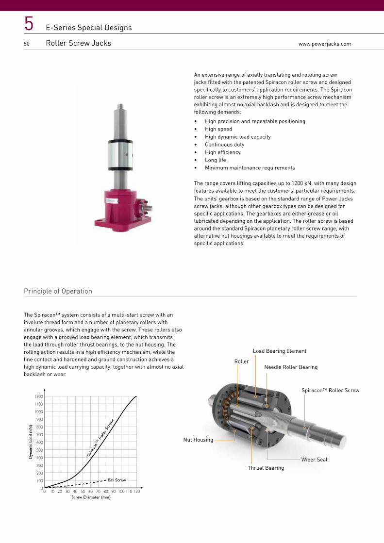
An extensive range of axially translating and rotating screw jacks fitted with the patented Spiracon roller screw and designed specifically to customers’ application requirements. The Spiracon roller screw is an extremely high performance screw mechanism exhibiting almost no axial backlash and is designed to meet the following demands:
• High precision and repeatable positioning• High speed• High dynamic load capacity• Continuous duty• High efficiency• Long life• Minimum maintenance requirements
The range covers lifting capacities up to 1200 kN, with many design features available to meet the customers’ particular requirements.The units’ gearbox is based on the standard range of Power Jacks screw jacks, although other gearbox types can be designed for specific applications. The gearboxes are either grease or oil lubricated depending on the application. The roller screw is based around the standard Spiracon planetary roller screw range, with alternative nut housings available to meet the requirements of specific applications.
Principle of Operation
The Spiracon™ system consists of a multi-start screw with an involute thread form and a number of planetary rollers with annular grooves, which engage with the screw. These rollers also engage with a grooved load bearing element, which transmits the load through roller thrust bearings, to the nut housing. The rolling action results in a high efficiency mechanism, while the line contact and hardened and ground construction achieves a high dynamic load carrying capacity, together with almost no axial backlash or wear.
Nut Housing
Roller
Load Bearing Element
Thrust Bearing
Spiracon™ Roller Screw
Wiper Seal
Needle Roller Bearing
E-Series Special Designs
Roller Screw Jacks

www.powerjacks.com
551
E-Series Special Designs
Roller Screw Jacks
Special Screw Jack Designs
The special screw jacks can be broken down into three categories:1. Modifications to the standard screw jacks
This would include non-standard painting or plating of the housing, 2 or 3 start threaded lifting screws, stainless steel lifting screws or worm shafts, increased closed heights, extended worm shafts, opposite threading of lifting screws, etc.
2. Additions to the standard screw jacks Items such as wear indicators, safety nuts, rotation monitoring kits, special lifting screw end fittings, encoder adapter flanges, etc.
3. Completely special screw jacks Where a modification of our existing range is not practical we have the facilities to design and manufacture screw jacks tailored specifically to your requirements.
E-Series Special Designs
Custom Features
50kNBased on TE1805
50kNBased on UE1806
25kNBased on UE1803
200kNBased on FE4819
Note 1. Units are not to scale on illustration

52
5www.powerjacks.com
E-Series Special Designs
Application Focus
GRAPHITE HANDLING MACHINE The Graphite Handling system was developed to retrieve graphite components, capping pieces and thermocouples from inside nuclear reactors, crush them for size reduction and deposit them into shielded flasks. The machine houses 4 types of flask.
The Crusher Jaws are driven by three 50 kN E-Series Screw Jacks, complete with Bevel gearbox, brake and motor, to size reduce the component. The selected Flask is raised into the docking position by two more 50kN screw jacks, driven by a single electric motor via bevel gearboxes. The size reduced component is deposited into the flask and the flask is returned to its storage position.
For more application examples see the ‘Power at Work’ brochure or www.powerjacks.com.

www.powerjacks.com
553
E-Series Special Designs
Application Focus
E-Series Special Designs
Application Focus
COIL SPRING LOAD LIMITER When an industrial machine needs to move a cover or lid onto a dead stop or sealing face it must do so precisely and positively, with contact on all dead stops or over the complete sealing face.
To push the cover into position precisely Power Jacks designed a special coil spring load limiter for the end of the jacks lifting screw.
For more application examples see the ‘Power at Work’ brochure or www.powerjacks.com.

E-Series
6
Screw JackAccessories

E-Series - Metric Machine Screw Jack
Accessories
155www.powerjacks.com

56
6www.powerjacks.com
E-Series Accessories
End Fittings
Top Plate
Clevis End
Fork End
Rod End
= =
A
ØG
ØBC
F
ØD
LJ
H
K
CB
C
DE
F
ØAØ
J
G
L
CD
E
ØB
LØA
J
C
D
ØA
Bas
e of
Scr
ew J
ack
Bas
e of
Scr
ew J
ack
Bas
e of
Scr
ew J
ack
Bas
e of
Scr
ew J
ack
ØB
ØFØE
M/N
M/N
M/N
M/N
L
= =
A
ØG
ØBC
F
ØD
LJ
H
K
CB
C
DE
F
ØAØ
J
G
L
CD
E
ØB
LØA
J
C
D
ØA
Bas
e of
Scr
ew J
ack
Bas
e of
Scr
ew J
ack
Bas
e of
Scr
ew J
ack
Bas
e of
Scr
ew J
ack
ØB
ØFØE
M/N
M/N
M/N
M/N
L
= =
A
ØG
ØBC
F
ØD
LJ
H
K
CB
C
DE
F
ØA
ØJ
G
L
CD
E
ØB
LØA
J
C
D
ØA
Bas
e of
Scr
ew J
ack
Bas
e of
Scr
ew J
ack
Bas
e of
Scr
ew J
ack
Bas
e of
Scr
ew J
ack
ØB
ØFØE
M/N
M/N
M/N
M/N
L
= =
A
ØG
ØBC
F
ØD
LJ
H
K
CB
C
DE
F
ØA
ØJ
G
L
CD
E
ØB
LØA
J
C
D
ØA
Bas
e of
Scr
ew J
ack
Bas
e of
Scr
ew J
ack
Bas
e of
Scr
ew J
ack
Bas
e of
Scr
ew J
ack
ØB
ØFØE
M/N
M/N
M/N
M/N
L

657www.powerjacks.com
E-Series Accessories
End Fittings
E-Series Accessories
End Fittings
Model E2626 E2501 E1802 E1805 E1810 E1820 E1830 E1850 E18100
Top
Pla
te
ØA 65 80 100 120 150 170 240 280 380
ØB 25 30 40 50 65 75 110 150 200
C 21 24 31.5 36.5 42 58 67 92 127
D 8 10 12 16 20 25 30 35 75
ØE 9 11 13.5 18 22 26 33 33 51
ØF (PCD) 45 55 70 85 110 120 170 215 290
L M10 x 1.5 M12 x 1.75 M20 x 2.5 M24 x 3 M36 x 4 M48 x 5 M72 x 4 M100 x 4 M125 x 4
M#1 Upright 95 125 145 185 200 265 325 390 560
Inverted 40 45 55 65 80 95 115 150 260
N#2Upright - 150 175 218 252 338 445 - -
Inverted - 45 55 65 80 95 115 - -
Model E2625 E2501 E1802 E1805 E1810 E1820 E1830 E1850 E18100
Cle
vis
End
ØA 10 12 16 20 22 30 45 60 90
ØB 25 30 40 50 65 75 110 150 200
C 56 63 79.5 91.5 120 143 167 217 297
D 30 36 46 60 66 80 120 150 210
E 15 18 23 30 33 40 60 75 105
L M10 x 1.5 M12 x 1.75 M20 x 2.5 M24 x 3 M36 x 4 M48 x 5 M72 x 4 M100 x 4 M125 x 4
J 15 20 30 35 40 50 80 110 140
M#1Upright 115 145 170 210 245 310 365 440 625
Inverted 60 65 80 90 125 140 155 200 325
N#2Upright - 170 200 243 297 383 485 - -
Inverted - 65 80 90 125 140 155 - -
Model E2625 E2501 E1802 E1805 E1810 E1820 E1830 E1850 E18100
Fork
End
ØA 10 12 20 25 35 50
Available on Request
Available on Request
Available on Request
B 10 12 20 25 35 50
C 20 24 40 50 70 96
D 40 48 80 100 144 192
E 20 24 40 50 72 96
F 15 18 30 36 54 73
G 52 62 105 132 188 265
ØJ 18 20 34 42 60 82
L M10 x 1.5 M12 x 1.75 M20 x 2.5 M24 x 3 M36 x 4 M48 x 5
M#1Upright 114 148 194 248 302 400
Inverted 59 68 104 128 182 230
N#2Upright - 173 224 281 354 473
Inverted - 68 104 128 182 230
Model E2625 E2501 E1802 E1805 E1810 E1820 E1830 E1850 E18100
Rod
End
A 43 50 77 94 125 160
Available on Request
Available on Request
Available on Request
ØB 10 12 20 25 35 50
C 15 18 27 32 42 60
ØD 29 34 53 64 82 112
F - 23 40 48 60 68
ØG 19 22 35 42 58 75
H 9 10 16 20 25 35
J 7 8 13 17 21 30
K 17 19 32 36 50 65
L M10 x 1.5 M12 x 1.75 M20 x 1.5 M24 x 2 M36 x 3 M45 x 3
M#1Upright 117 150 190 242 283 367
Inverted 62 70 100 122 163 197
N#2Upright - 175 220 275 335 440
Inverted - 70 100 122 163 197
Note1. M = For Machine Screw Jacks2. N = For Ball Screw Jacks, Standard Lead only.

58
6www.powerjacks.com
E-Series Accessories
Machine Screw Jack Bellows Boots
Features • Protects the screw from dust and dirt• Guards against moisture and corrosive contaminants• Helps maintain the proper lubrication• Boots are made of P.V.C. coated nylon with sewn construction. Other materials
are available for applications involving high temperatures, highly corrosive atmospheres and other special conditions.
Boot Dimensions
Model A B C D E
E2625-B 25 60 100 13 13
E2501-B 30 70 110 15 15
E1802-B 40 90 120 15 23
E1805-B 50 115 140 15 31
E1810-B 65 136 150 15 31
E1820-B 75 165 165 20 20
E1830-B 110 220 191 20 20
E1850-B 150 285 210 20 45
E18100-B 200 220 244 20 20
Model E2625-B E2501-B E1802-B E1805-B E1810-B E1820-B E1830-B E1850-B E18100-B
F
Stroke 0 → 150 10 - - - - - - - -
Stroke 0 → 300 20 20 20 20 20 20 20 20 20
Stroke 300 → 600 30 35 30 30 30 30 30 30 30
Stroke 600 → 750 - 40 - - - - - - -
Stroke 600 → 900 - - - 45 - - - - -
Stroke 750 → 1000 - 60 - - - - - - -
Stroke 600 → 1050 - - 50 - 50 50 50 50 50
Stroke 900 → 1050 - 60† - 50 - - - - -
Stroke 1000 → 1250 - - 70 - - - - - -
Stroke 1050 → 1500 - - 100† 70 70 70 70 70 70
Stroke 1500 → 1800 - - - 95 - 90† 100† - -
Stroke 1500 → 2000 - - - - 105 - - - -
Stroke 1800 → 2100 - - - 110† - 110† - - -
Stroke 2000 → 2500 - - - - 120† - - - -
Stroke 2100 → 2500 - - - 130† - - - - -
Stroke 2500 → 3000 - - - 160† - - - - -
Note 1. F = Bellows boot minimum closed thickness2. - = Not applicable3. † = Control tapes fitted (approximately 20 mm increase to outer diameter).
øA
D
F
E
øB
øC

659www.powerjacks.com
E-Series Accessories
Machine Screw Jack Bellows Boots
E-Series Accessories
Upright Machine Screw Jack Bellows Boots
Standard Dimensions for all Upright Metric Machine Screw Jacks including Keyed
Model E2625-B E2501-B E1802-B E1805-B E1810-B E1820-B E1830-B E1850-B E18100-B
G
Stroke 0 → 150 100 - - - - - - - -
Stroke 0 → 300 110 140 160 200 215 280 330 390 560
Stroke 300 → 600 120 155 170 210 225 290 340 400 565
Stroke 600 → 750 - 160 - - - - - - -
Stroke 600 → 900 - - - 225 - - - - -
Stroke 750 → 1000 - 180 - - - - - - -
Stroke 600 → 1050 - - 190 - 245 310 360 420 585
Stroke 900 → 1050 - - - 230 - - - - -
Stroke 1000 → 1250 - 180† - - - - - - -
Stroke 1050 → 1500 - - 210 250 265 330 380 440 605
Stroke 1500 → 1800 - - 240† 275 - 350† 410† - -
Stroke 1500 → 2000 - - - - 300 - - - -
Stroke 1800 → 2100 - - - 290† - 370† - - -
Stroke 2000 → 2500 - - - - 315† - - - -
Stroke 2100 → 2500 - - - 310† - - - - -
Stroke 2500 → 3000 - - - 340† - - - - -
H Extra Closed Height for Clevis 20 20 25 25 45 45 40 50 65
Standard Dimensions for all Upright Metric Anti-Backlash Screw Jacks including Keyed
Model E4625-B E4501-B E4802-B E4805-B E4810-B E4820-B E4830-B E4850-B E48100-B
G
Stroke 0 → 150 105 - - - - - - - -
Stroke 0 → 300 115 140 160 200 215 280 345 415 585
Stroke 300 → 600 120 155 170 210 225 290 355 425 585
Stroke 600 → 750 - 160 - - - - - - -
Stroke 600 → 900 - - - 225 - - - - -
Stroke 750 → 1000 - 180 - - - - - - -
Stroke 600 → 1050 - - 190 - 245 310 375 445 600
Stroke 900 → 1050 - - - 230 - - - - -
Stroke 1000 → 1250 - 180† - - - - - - -
Stroke 1050 → 1500 - - 210 250 265 330 395 465 620
Stroke 1500 → 1800 - - 240† 275 - 350† 425† - -
Stroke 1500 → 2000 - - - - 300 - - - -
Stroke 1800 → 2100 - - - 290† - 370† - - -
Stroke 2000 → 2500 - - - - 315† - - - -
Stroke 2100 → 2500 - - - 310† - - - - -
Stroke 2500 → 3000 - - - 340† - - - - -
H Extra Closed Height for Clevis 20 20 25 25 45 45 40 50 65
Threaded End Top Plate Clevis End
G G G + H
Closed Heights

60
6www.powerjacks.com
Standard Dimensions for all Inverted Metric Machine Screw Jacks including Anti-Backlash and Keyed
Model E2624-B E2500-B E1801-B E1804-B E1809-B E1819-B E1829-B E1849-B E18099-B
M Mounting Plate 10 10 15 15 20 20 30 30 50
K
Stroke 0 → 150 70 - - - - - - - -
Stroke 0 → 300 80 85 105 120 130 135 165 215 260
Stroke 300 → 600 90 100 115 130 140 145 175 225 260
Stroke 600 → 750 - 105 - - - - - - -
Stroke 600 → 900 - - - 145 - - - - -
Stroke 750 → 1000 - 125 - - - - - - -
Stroke 600 → 1050 - - 135 - 160 165 195 245 280
Stroke 900 → 1050 - - - 150 - - - - -
Stroke 1000 → 1250 - 125† - - - - - - -
Stroke 1050 → 1500 - - 155 170 180 185 215 265 300
Stroke 1500 → 1800 - - 185† 195 - 205† 245† - -
Stroke 1500 → 2000 - - - - 215 - - - -
Stroke 1800 → 2100 - - - 210† - 225† - - -
Stroke 2000 → 2500 - - - - 230† - - - -
Stroke 2100 → 2500 - - - 230† - - - - -
Stroke 2500 → 3000 - - - 260† - - - - -
L Extra Closed Height for Clevis 20 20 25 25 45 45 40 50 65
p Extra Closed Height for Keyed Anti-Backlash Units 4 6 4.5 9 10 19 13 33 115
Notes for all metric machine screw jacks with bellows boots1. Supplied complete with a set of corrosion-resistant ‘jubilee’ clips (2) suitable for fitting over collar diameters.2. † Control tapes are fitted (approximately 20 mm increase to outer diameter). 3. For horizontal installation exceeding 450 mm of travel, internal boot guides are recommended.
4. Customers with threaded end screw jacks must provide a fixing for the unattached collar (★). 5. Bellows boots for Rotating Screw Jacks consult Power Jacks Ltd. 6. For other sizes, raises, and materials please consult Power Jacks Ltd. 7. All dimensions in millimetres unless otherwise stated. 8. Dimensions subject to change without notice.
9. Screw Jack mounting plate and bellows boot mounting plate are usually all part of the customers superstructure (★ ★). For other options
consult Power Jacks.
Boot Mounting Plate, to suit collar size.Typically ØB x (E+5
mm fitting allowance) thick.
★ ★
Screw jack Mounting Plate, ‘M’ thick. Alter thickness to suit
application. ★ ★
K K K+L
E-Series Accessories
Inverted Machine Screw Jack Bellows Boots
Closed Heights

661www.powerjacks.com
E-Series Accessories
Ball Screw Jack Bellows Boots
Features • Protects the screw from dust and dirt
• Guards against moisture and corrosive contaminants
• Helps maintain the proper lubrication
• Boots are made of P.V.C. coated nylon with sewn construction. Other materials
are available for applications involving high temperatures, highly corrosive
atmospheres and other special conditions.
Boot Dimensions
Model A B C D E
E28501-B 30 75 114 12 12
E3802-B 40 66 120 15 15
E3805-B 50 85 140 15 15
E3810-B 65 100 150 15 15
E3820-B 75 105 165 20 20
E3830-B Available on Request
E3860-B Available on Request
Model E28501-B E3802-B E3805-B E3810-B E3820-B E3830-B E3860-B
F
Stroke 0 → 300 16 20 20 20 20
Avai
labl
e on
Req
uest
Avai
labl
e on
Req
uest
Stroke 300 → 600 32 30 30 30 30
Stroke 600 → 900 - - 45 - -
Stroke 600 → 1050 56 50 - 50 50
Stroke 900 → 1050 - - 50 - -
Stroke 1050 → 1500 80 70 70 70 70
Stroke 1500 → 1800 - 100† 95 - 90†Stroke 1500 → 2000 - - - 105 -
Stroke 1800 → 2100 - - 110 - 110†Stroke 2000 → 2500 - - - 120† -
Stroke 2100 → 2500 - - 130† - -
Stroke 2500 → 3000 - - 160† - -
Note 1. F = Bellows boot minimum closed thickness2. - = Not applicable consult Power Jacks Ltd3. † = Control tapes fitted (approximately 20 mm increase to outer diameter).
øA
D
F
E
øB
øC

62
6www.powerjacks.com
E-Series Accessories
Upright Ball Screw Jack Bellows Boots
Standard Dimensions for all Upright Metric Ball Screw Jacks
Model E28501-B E3802-B E38021-B E3805-B E38051-B E3810-B E38101-B E3820-B E38201-B E3830-B E3860-B
G
Stroke 0 → 150 - - - - - - - - -
Avai
labl
e on
Req
uest
Avai
labl
e on
Req
uest
Stroke 0 → 300 166 180 200 230 270 255 285 323 361
Stroke 300 → 600 182 190 210 240 280 265 295 333 371
Stroke 600 → 900 - - - 255 295 - - - -
Stroke 600 → 1050 206 210 230 - - 285 315 353 391
Stroke 900 → 1050 - - - 260 300 - - - -
Stroke 1050 → 1500 230 230 250 280 320 305 335 373 411
Stroke 1500 → 1800 - 260† 280† 305 345 - - 393† 431†Stroke 1500 → 2000 - - - - - 340 370 - -
Stroke 1800 → 2100 - - - 320† 360† - - 413† 451†Stroke 2000 → 2500 - - - - - 355† 385† - -
Stroke 2100 → 2500 - - - 340† 380† - - - -
Stroke 2500 → 3000 - - - 370† 410† - - - -
HExtra Closed Height
for Clevis 20 25 25 25 25 45 45 45 45
Note
1. Supplied complete with a set of corrosion-resistant ‘jubilee’ clips (2) suitable for fitting over collar diameters
2. † Control tapes are fitted (approximately 20 mm increase to outer diameter).
3. For horizontal installation exceeding 450 mm of travel, internal boot guides are recommended.
4. Customers with threaded end Screw Jacks must provide a fixing for the unattached collar (★ ).
5. Bellows boots for Rotating Screw Jacks consult Power Jacks Ltd.
6. For other sizes, raises, and materials please consult Power Jacks Ltd.
7. All dimensions in millimetres unless otherwise stated.
Closed Heights
Threaded End Top Plate Clevis End
G G G + H

663www.powerjacks.com
E-Series Accessories
Upright Ball Screw Jack Bellows Boots
E-Series Accessories
Inverted Ball Screw Jack Bellows Boots
Standard Dimensions for all Inverted Metric Ball Screw Jacks
Model E28501-B E3801-B &E38011-B
E3804-B &E38041-B
E3809-B &E38091-B
E3819-B &E38191-B
E3829-B &E38291-B
M Mounting Plate Thickness 10 15 15 20 20 30
J
Stroke 0 → 150 - - - - -
Stroke 0 → 300 61 100 105 120 140
Avai
labl
e on
Req
uest
Raise 300 → 600 77 110 115 130 150
Stroke 600 → 900 - - 130 - -
Stroke 600 → 1050 101 130 - 150 170
Stroke 900 → 1050 - - 135 - -
Stroke 1050 → 1500 125 150 155 170 190
Stroke 1500 → 1800 - 180† 170 - 210†Stroke 1500 → 2000 - - - 195 -
Stroke 1800 → 2100 - - 185† - 230†Stroke 2000 → 2500 - - - 210† -
Stroke 2100 → 2500 - - 205† - -
Stroke 2500 → 3000 - - 235† - -
K Extra Closed Height for Clevis 20 25 25 45 45
Note
1. Supplied complete with a set of corrosion-resistant ‘jubilee’ clips (2) suitable for fitting over collar diameters.
2. † Control tapes are fitted (approximately 20 mm increase to outer diameter).
3. For horizontal installation exceeding 450 mm of travel, internal boot guides are recommended.
4. Customers with threaded end screw jacks must provide a fixing for the unattached collar (★ ).
5. Bellows boots for rotating screw jacks consult Power Jacks Ltd.
6. For other sizes, and materials please contact Power Jacks Ltd.
7. All dimensions in millimetres unless otherwise stated.
8. Dimensions subject to change without notice.
9. Screw Jack mounting plate and bellows boot mounting plate are usually all part of the customers superstructure (★ ★). For other options
consult Power Jacks.
Threaded End Top Plate Clevis End
J J J + K
Closed Heights
Boot Mounting Plate,to suit collar size. Typically ØB x (E+5 mm fitting allowance) thick.
★ ★
Screw Jack Mounting Plate,
‘M’ thick. Alter thickness to suit
application
★ ★.

64
6www.powerjacks.com
E-Series Accessories
Limit Switches on Cover Pipe
End of Travel Proximity Sensors Sensor Kit • Inductive Proximity Sensors as standard, others available on
request.
• No contact so no wearing parts.
• 2 wire sensor for either Normally Closed (NC) or Normally
Open (NO) switching.
• Sensor has rugged one-piece metal housing.
• Optical setting aid with 2 LED colour settings:- Red LED
indicates just in sensing range. Yellow LED only indicates
within 80% safe sensing range.
• M12 plug in connection for fast change-ability.
• M12 sockets available straight or angled with 5-m cable
(other cable lengths available on request).
• Full 360° visibility for switching with 4 yellow LED’s at 90°
offset.
• Sensor kit includes - sensor, mounting ring, target ring and
modification to screw jacks cover pipe.
Metric Upright & Inverted Screw Jacks
Capacity Rating
(kN)
Switch Dia
(mm)
A1(mm)
A2(mm)
B(mm)
C(mm)
D(Ømm)
E(mm)
±5
F(mm)
SwitchAdjustment
(mm)
25 12 50 40 Stroke + 15
40 48 83 15 ±10
50 12 50 40 Stroke + 18
40 60 90 15 ±10
100 18 50 40 Stroke + 24
45 73 103 20 ±10
200 18 50 40 Stroke +24
45 89 110 20 ±10
Note
1. All dimensions in mm unless otherwise stated.
2. Other sizes are available with cover pipe limit switches.
Consult Power Jacks Ltd for advice.
ØD
C
Stroke
E
Switch
SwitchCover PipeCover
Pipe
B
A2
E
Stroke
C
F
B
MOUNTING PLATEA1
Switch
Switch
ØD
End of Travel Electro-Mechanical Switches
The screw jacks can be fitted with electro-mechanical limit switches in a similar design. For dimensions please consult Power Jacks Ltd.

665www.powerjacks.com
E-Series Accessories
Limit Switches on Cover Pipe
E-Series Accessories
Rotary Limit Switch - RLS
Rotary limit switches can be used as end of travel limit switches, with the option of intermediate switches as well. These units are mounted onto a screw jacks free worm shaft and offer an alternative where bottom pipe mounted limit switches are not possible e.g. rotating screw jacks. Up to 8 limit switches can be accommodated in one enclosure (IP66). Operating temperature -40°C → +80°C.
For full details on the RLS-51 limit switch refer to separate catalogue.
Metric Screw Jack Capacity (kN)
25 50
Adapter Mounting
Std. Part A B øC
Std. Part A B øC
B5 O - - - O - - -
B14 P 117 10 70 P 133 10 89
Metric Screw Jack Capacity (kN)
100 200
Adapter Mounting
Std. Part A B øC
Std. Part A B øC
B5 P 152 13 98 P 174 13 125
B14 O - - - O - - -
The mounting kit includes the flexible coupling and drive adapter.
RLS-51 Rotary Limit Switch
Gear Size
Usable revs. selected
Usable revs. theoretical
with 15° cam discs
Gear Ratio
1 rev. of the drive shaft -
corresp. to an ang. motion of
cam disc =°
Change - over contact reset rev. at driving
shaft
Max drive speed (RPM)
Min drive shaft speed (only for change - over
contact)
L1 (mm)
Limit Switches
2 4 6 8
1
4.1 4.16 4.285 84 0.00714 1000 0.67
132 132 157 1576.5 6.88 7.083 50.8 0.0118 1200 1.1
11 11.23 11.56 31.14 0.0193 1500 1.8
2
17.5 17.84 18.361 19.6 0.0306 1800 2.9
132 132 157 18229 29.5 30.35 11.86 0.0505 1800 4.7
48 48.13 49.538 7.27 0.0825 1800 7.7
3
75 76.45 78.678 4.57 0.131 1800 12.2
132 132 157 182125 126.39 130.054 2.77 0.2166 1800 20.2
205 206.26 212.272 1.69 0.3536 1800 33
4
323 327.6 337.135 1.06 0.5616 1800 52
132 157 182 207540 541.5 557.284 0.65 0.9284 1800 87
880 883.8 909.59 0.4 1.515 1800 141
5
1384 1403.7 1444.62 0.25 2.406 1800 224
132 157 182 2072288 2320.2 2387.96 0.15 3.978 1800 371
3735 3787.1 3897.58 0.09 6.493 1800 606
6
5900 6014.77 6190.204 0.06 10.313 1800 *
157 157 182 2079800 9942.2 10232.407 0.04 17.047 1800 *
16000 16227.6 16701.17 0.02 27.824 1800 *
Note1. More than 8 contacts on request.2. Dimensions with more than 8 contacts and with special executions, eg. potentiometer, on request.3. RLS-51 B5 Flange thickness = 4mm.4. Options available include Anti-condensation heaters, potentiometer, pulse transmitter, encoder, aluminum housing and
VBG-70 STAGE technolgy.5. Mounting kits available for all screw jacks. For those not listed, consult Power Jacks.

66
6www.powerjacks.com
E-Series Accessories
Rotary Limit Switch - SKA
The SKA rotary limit switch is a compact 2-position limit switch designed for screw jack and linear actuator applications. For full details on the SKA limit switch refer to separate catalogue.
These limit switches are generally used for existing installations. For new applications, Power Jacks recommend the use of the RLS-51 Rotary Limit Switch.
A (mm) 25kN 50kN 100kN 200kN 300kN 500kN 1000kN
Close Mount N/A 137 180 195 223 252 290
Extended Mount (If Retro-fit) 176 199 224 234 274 313 374
Note1. All dimensions are in millimetres (mm) unless otherwise stated.
Model No. Max. Voltage Max. Amps Max. Worm Rev.
Max Raise Max Allowable Drift
Notch Adjust-mentAC DC AC DC
SKA-6000-A-10 250 15 1095 1095/TPU 24/TPU 1/TPU
SKA-6000-A-20 2190 2190/TPU 48/TPU 2/TPU
SKA-6000-A-40 4380 4380/TPU 96/TPU 4/TPU
SKA-6000-B-10 480 125250
15 0.50.25
750 750/TPU 29/TPU 1/TPU
SKA-6000-B-20 1500 1500/TPU 57/TPU 2/TPU
SKA-6000-B-40 3000 3000/TPU 115/TPU 4/TPU
SKA-6000-C-10 120240480800
115230
15 0.800.40
675 675/TPU 38.5/TPU 1/TPU
SKA-6000-C-20 1350 1350/TPU 77/TPU 2/TPU
SKA-6000-C-40 2700 2700/TPU 154/TPU 4/TPU
Notes1. Operating Temperaturee -29 °C → 65 °C2. Enclosure IP65.
1/2” NPT
76mm
90.5mm 159mm
168mm
A

667www.powerjacks.com
E-Series Accessories
Rotary Limit Switch - SKA
E-Series Accessories
Motor Adapter
• Standard adapters for 25 kN - 300 kN metric machine screw and ball screw jacks• Designed for standard IEC frame sizes• Allows direct motor coupling on either side of the screw jack input shaft• Complete with drive coupling and mounting hardware• NEMA frame size versions available on request• Adapters for other metric screw jacks and mounting arrangements available on request.
Note• When direct coupling a motor to a screw jack, it is necessary to match motor power to screw jack load so the motor does not exceed
the maximum power for the screw jack gear set.
Motor Adapters Capacity (kN)
25 50 100 200 300
Frame Size
Motor Mounting
Std. Part
A B C Std. Part
A B C Std. Part
A B C D Std. Part
A B C D Std. Part
A B C
71 B5 P 145 14 80 O - - - O - - - - O - - - - O - - -
B14 C105 O - - - O - - - O - - - - O - - - - O - - -
80 B5 P 160 14 80 P 187 14 100 O - - - - O - - - - O - - -
B14 C120 P 145 14 80 O - - - O - - - - O - - - - O - - -
90 B5 P 160 14 80 P 187 14 100 P 212 14 110 98 P 212 14 110 98 P 250 14 120
B14 C140 P 145 14 80 O - - - P 212 14 110 98 P 212 14 110 98 P 260 14 120
100 B5 P 160 14 80 P 207 14 100 P 212 14 110 98 P 212 14 110 98 P 280 14 120
B14 C160 P 160 14 80 P 187 14 100 P 212 14 110 98 P 212 14 110 98 P 260 14 120
112 B5 O - - - P 207 14 100 P 212 14 110 98 P 212 14 110 98 P 280 14 120
B14 C190 O - - - P 187 14 100 P 212 14 110 98 P 212 14 110 98 P 260 14 120
132 B5 O - - - P 207 14 100 O - - - - O - - - - O 280 14 120
B14 C200 O - - - P 207 14 100 P 212 14 110 98 P 232 14 110 98 P 280 14 120
A
C
B
D
Motor

68
6www.powerjacks.com
E-Series Accessories
Trunnion Mounts
Capacity (kN) Type A B C D E F G H J K L M N Weight
(kg)
5 1 114 114 57 60 - 30 110 85 15 20 10 50 M8 (2) 1.24
10 1 175 135 67.5 80 - 40 130 100 20 25 12.5 58 M10 (2) 2.27
25 2 160 120 60 165 135 50 110 80 25 30 15 72 M12 (4) 3.27
50 2 200 160 80 205 170 575 150 115 35 40 20 95 M16 (4) 8.90
100 2 270 200 100 225 180 52.5 190 145 45 50 25 130 M20 (4) 15.57
Trunnion mounts bolt onto screw jack base plates.
Note1. Trunnion mounts for other screw jack sizes are available on request2. All dimensions in millimetres (mm) unless otherwise stated.
N
G
H
B
A
C
ØM
Ø J
K
L
F D
E
N
F
ØM
H GBA
C K
Ø J
L
D
Type 1 Type 2

669www.powerjacks.com
E-Series Accessories
Trunnion Mounts
E-Series Accessories
Stop Nuts & Hand Wheels
Notes:1. Material: Polished aluminium casting and rotating handle2. Bored and keyed to BS4235 Part 13. All dimensions in millimetres unless otherwise stated4. Other types of hand wheels are available on request. Consult Power Jacks.
Model A B C ØD ØE H7 BoreHW 005 40 14 36 98 24 Ø10HW 010 50 22 38 157 32 Ø14HW 025 56 24 43 198 40 Ø16HW 050 56 24 43 198 40 Ø19HW 100 66 30 44 247 49 Ø25
Hand Wheels
Stop Nut
Machine Screw jack
Model Extra (mm)Upright Inverted
E2525 On RequestE2501 17 50E1802 21 21E1805 38 38E1810 41 41E1820 39 39E1830 On RequestE1850 On RequestE18100 On RequestE18150 On RequestE18200 On Request
Ball Screw Jack
Model Extra (mm)Upright Inverted
E28501 On RequestE3802 30 30E3805 57 57E3810 60 60E3820 56 56E3830 On RequestE3860 On Request

E-Series
Page Title3E-SeriesE-Series
7
USEFUL PERFORMANCE & OPERATIONAL DETAIL FOR SCREW JACKS
ENGINEERING GUIDE
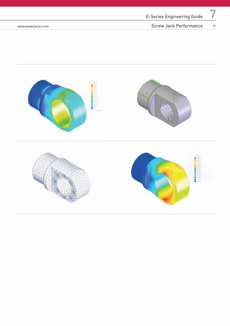
771
E-Series
Page Title www.powerjacks.com
E-Series Engineering Guide
Screw Jack Performance

72
7www.powerjacks.com
Euler Buckling Curve
Column strength cut off point due to slenderness ratio considerations
Applications in hatched area - consult Power Jacks Ltd for detailed analysis.
E-Series Engineering Guide
Metric Machine Screw Jack Column Strength Charts
Column Length Correction Factors, Fcb
Important Notes1. All charts are rated for industrial cargo with a safety factor of 3.5. 2. For human cargo a safety factor of 5 is recommended. To alter the permissible compressive load (WP) for human cargo multiply the load
selected from the chart by 0.7 e.g. WPHC
= WP *0.7.
Wp
L L L
Wp
Wp
Fixed/Free Pinned/Pinned Fixed/Guided

773www.powerjacks.com
E-Series Engineering Guide
Metric Machine Screw Jack Column Strength Charts
E-Series Engineering Guide
Metric Machine Screw Jack Column Strength Charts
Note1. Column end constraints based on A.I.S.C. recommended values2. All screw jack column strength charts show a Euler buckling curve and three scales for the appropriator end
condition for the application under analysis.

74
7www.powerjacks.com
E-Series Engineering Guide
Metric Ball Screw Jack Column Strength Charts

775www.powerjacks.com
E-Series Engineering Guide
Metric Ball Screw Jack Column Strength Charts
E-Series Engineering Guide
Metric Ball Screw Jack Column Strength Charts

76
7www.powerjacks.com
Critical Screw Speed Factors, Fcs
Metric Machine Screw Critical Screw Speed (Shaft Whirling)
Metric Ball Screw Critical Screw Speed (Shaft Whirling)
E-Series Engineering Guide
Critical Screw Speed

777www.powerjacks.com
E-Series Engineering Guide
Critical Screw Speed
E-Series Engineering Guide
Screw Jack Key Torque
The key torque is caused by the tendency of the lifting screw to rotate. It is a function of the screw lead, screw efficiency and the load. It is not affected by the screw jack unit gear ratio.
NoteThe values below are given at rated load. For a smaller load reduce the key torque in direct proportion.
Machine Screw Jacks
Capacity (kN) Screw Diam (mm) Lead (mm) Key Torque (Nm)
5 16 0.003 8
5 16 0.006 11
10 20 0.005 22
10 20 0.010 30
25 30 0.006 76
25 30 0.012 102
50 40 0.009 210
50 40 0.018 290
100 55 0.012 575
100 55 0.024 780
200 65 0.012 1300
200 65 0.024 1705
300 95 0.016 2805
300 95 0.032 3610
500 120 0.016 5645
500 120 0.032 6975
1000 160 0.020 14890
1000 160 0.040 18220
Ball Screw Jacks
Capacity (kN) Screw Diam (mm) Lead (mm) Key Torque (Nm)
10 20 0.005 9
10 - - -
25 25 0.005 23
25 25 0.01 43
50 40 0.01 88
50 40 0.02 167
100 50 0.01 181
100 50 0.02 340
200 63 0.01 370
200 63 0.02 690
300 80 0.02 1030
500 On Request

78
7www.powerjacks.com
Machine Screw Jacks
Metric Machine Screw Jack
Capacity (kN) 5 10 25 50 100 200 300 500 1000
Max. Slide Load 300mm Offset (N) 100 150 540 1130 2900 3350 17500 37800 83400
Ball Screw Jacks
Metric Ball Screw Jack
Capacity (kN) 10 25 25 50 50 100 100 200 200 300 500
Ball Screw Lead (mm) 5 5 10 10 20 10 20 10 20 20 *
Max. Slide Load 300mm Offset (N) 105 195 195 980 980 1570 1570 2060 2060 4340 *
*Consult Power Jacks.
To calculate maximum side load for different raises for screw jacks in tension under full rated load use the following formula to modify the above tabulated values.
Permissable Max. Side Load
for Actual Offset=
Max Side Load Rating Tabulated x Stated Offset
Actual Offset
NoteThe correct units must be used
Important Notes
1. These figures are for Screw Jacks in tension only.
2. The figures given above are permissible side load ratings, however, we recommend that all side loads be carried by guides in your
arrangement and not by the screw and nut.
3. Life of the lifting screw and nut will be adversely affected the more side load they see.
4. These figures are based on acceptable stresses in the lifting screw and not on lifting screw deflection.
5. For maximum side load ratings for screw jacks in compression consult Power Jacks Ltd.
6. For precise calculations for your application consult Power Jacks Ltd.
E-Series Engineering Guide
Side Load Rating
Maximum Jack Side Load Ratings with Full Jack Rated Load in Tension

779www.powerjacks.com
E-Series Engineering Guide
Side Load Rating
E-Series Engineering Guide
Radial Loads on Screw Jack Worm Shaft
For applications where a screw jack is belt/chain driven, a calculation must be made to determine the radial force (FR) and compared to the allowable radial load exerted on the worm shaft, that must not exceed those tabulated below. The values below are maximum values for the screw jacks at rated load regardless of worm speed or load direction and the radial load applied midway along the key of the worm shaft. For all applications the sprocket, gear etc. should be positioned as close as possible to the screw jack housing in order to reduce bearing loads and shaft stresses and to prolong life.
Radial Force, FR =2000 x T x K
D
Where FR = Radial Load (N) T = Torque applied to the screw jacks input shaft (Nm) K = Factor from table below D = PCD in mm of gear, sprocket
Transmission Element Factor K
Chain sprocket 1
Gears (spur or helical pinion) 1.25
V-Belt pulley 1.5
Flatbelt pulley 2.0
Metric Machine Screw Jack
Capacity (kN) 25 50 100 200
Radial Load (N) 440 1100 1200 1600
Metric Ball Screw Jack
Capacity (kN) 5 10 25 50 100 200 300 500 1000
Radial Load (N) 180 325 380 740 1000 1600 2170 2190 2220

80
7www.powerjacks.com
Machine Screw Jacks
Component Normal Backlash
Lifting Screw and Nut 0.12mm → 0.2mm (0.005” → 0.008”)Load Bearings 0.00mm → 0.03mm (0.000” → 0.001”)
Total 0.12mm → 0.23mm (0.005” → 0.009”)
Note
1. The lifting screw backlash will increase during operation due to wear of threads in the nut
2. Axial play can be reduced by altering the load bearings preload to eliminate bearing play or by
specifying a screw jack with the Anti-Backlash feature
3. For exact backlash ratings for an individual unit consult Power Jacks.
Anti-Backlash Option
This unit can be adjusted for screw thread and bearing clearances to a minimum of 0.025 mm (0.001”). Some clearances must be maintained to keep torque requirements within reason and to provide adequate space for a lubrication film to form.
Ball Screw Jacks
Component Normal Backlash
Ball Track and Nut 0.05mm → 0.15mm (0.002” → 0.006”)Load Bearings 0.00mm → 0.03mm (0.000” → 0.003”)
Total 0.05mm → 0.18mm (0.0002” → 0.007”)
Note
1. For exact backlash ratings for an individual unit consult Power Jacks.
2. Ball nuts can be supplied with zero backlash or with adjustable backlash via a special twin nut assembly (twin nut assembly for
rotating screw units only). Consult Power Jacks for details.
3. Altering the load bearings preload to eliminate bearing play can reduce axial play.
4. There is no Anti-Backlash nut feature for the gear sets of these screw jacks.
Pitch Deviation of Lifting Screw
Lifting Screw Pitch Deviation
Machine Screw 0.05mm → 0.25mm per 300mmBall Screw 0.025mm → 0.050mm per 300mm (DIN Class 5.7)
Note
1. Pitch deviation is cumulative and NOT detrimental to the operation of the Screw Jack
2. The Lifting screws are manufactured from material with a straightness tolerance of 0.2 mm per metre
3. Pitch deviation is related to the cutting machines tolerance and the material used.
E-Series Engineering Guide
Axial Backlash Ratings

781www.powerjacks.com
E-Series Engineering Guide
Axial Backlash Ratings
E-Series Engineering Guide
Lateral Movement Ratings
Metric Machine Screw Jacks
Stroke (mm) 5kN 10kN 25kN 50kN 100kN 200kN 300kN 500kN 1000kN
100 0.7 0.6 0.8 1.0 1.0 0.4 0.4 0.7 0.7
200 1.3 1.1 1.4 1.7 1.7 0.7 0.6 1.0 1.0
300 1.9 1.5 1.9 2.3 2.3 0.9 0.8 1.3 1.3
400 2.5 2.0 2.5 2.9 2.9 1.2 1.0 1.7 1.6
500 3.1 2.4 3.1 3.6 3.6 1.4 1.2 2.0 1.9
600 3.7 2.8 3.6 4.2 4.2 1.6 1.4 2.3 2.2
700 4.3 3.3 4.2 4.8 4.8 1.9 1.6 2.6 2.4
800 4.8 3.7 4.8 5.5 5.5 2.1 1.8 2.9 2.7
900 5.4 4.2 5.3 6.1 6.1 2.4 1.9 3.2 3.0
1000 6.0 4.6 5.9 6.7 6.7 2.6 2.1 3.6 3.3
Notes1. Values quoted above are the maximum expected lateral movement for the given raise and screw jack model.2. Does not allow for possible deflection due to side loads.3. Lateral movements are for information only. For best results we recommend guides where possible.4. Lateral movements will be reduced if the screw jack is fitted with secondary guides.5. The above movements apply to machine screw jack only and not ball screw jacks. Permitting lateral movement on the ball screw jack under
load will exert side thrust on the ball screw and ball nut and will be detrimental to the ball screw and nut life. Ball screw applications should be guided to ensure a minimum of lateral movement.
6. Where lateral movement is critical consult Power Jacks for exact values for the application.

82
7www.powerjacks.com
How a Rotating Screw Jack Works
The rotation of the worm shaft causes the worm gear to rotate. For rotating screw jacks the lead screw is fixed to the worm gear and they rotate at the same speed. The lifting nut moves along the lead screw. As the worm gear turns, the friction forces on the screw thread act to turn the nut also. The greater the load on the screw jack unit, the greater the tendency of the nut to turn. If the nut turns with the screw, it will not raise the load. Therefore the nut needs to be fixed to a structure to prevent rotation. The restraining torque required for the structure, also known as the “lead screw key torque” can be found on P77 or requested from Power Jacks.
E-Series Engineering Guide
Operation
Anti-Backlash Screw Jack – When To Use
For reduced axial backlash of the lead screw in the screw jack select a model with the “Anti-Backlash” mechanism. This is typically used when the load direction changes from tension to compression and minimal axial backlash is required. This design is only available for translating screw jacks. It can be combined with Anti-Rotation mechanism as well.
How a Translating Screw Jack Works
The rotation of the worm shaft causes the worm gear to rotate. For translating screw jacks the worm gear is threaded to accommodate the lead screw thread. The lead screw translates through the gear. As the worm gear turns, the friction forces on the screw thread act to turn the screw also. The greater the load on the screw jack unit, the greater the tendency of the screw to turn. If the screw turns with the nut (worm gear), it will not raise the load. In those cases where a single unit is used, and where the load cannot be restrained from turning, it is necessary to use a screw jack with an anti-rotation mechanism (keyed screw jack). Lead screw key torque (refer to P77 or request from Power Jacks) must be checked as excessively heavy unguided loads could break the Anti-rotation mechanism (key).

783www.powerjacks.com
E-Series Engineering Guide
Operation
E-Series Engineering Guide
Operation
Input Torque Required for a Screw Jack
The input torque for a single screw jack depends on the load, the worm gear ratio, type of screw (machine screw, ball screw or roller screw) and the pitch of the lead screw. Torque values are listed in the individual product specification charts based on capacity loads. For loads from 25% to 100% of screw jack model capacity, torque requirements are approximately proportional to the load. NoteThe input torque, as well as the efficiency and side load ratings, is the same for both translating screw and rotating screw jacks.
Maximum Input Power & Speed for a Screw Jack
The input power to the screw jacks should not exceed the power rating shown in the specifications table. Maximum input speed in rpm (revolutions per minute) to a screw jacks worm shaft should not exceed 1800 rpm for E-Series screw jacks.
Efficiency of a Screw Jack
Screw Jack model efficiencies are listed in the individual product specification charts.
Expected Life of a Screw Jack
The life expectancy of a screw jacks lead screw, bearings, nut and worm gear set varies considerably due to the extent of lubrication, abrasive or chemical action, overloading, excessive heat, improper maintenance, etc. For detailed life calculations, consult Power Jacks.
Screw Jack with Anti-Rotation (Keyed) Mechanism
This design is only available for translating screw jacks. If the structure/object connected to the lead screw is not prevented from rotating or the lead screw is not always in contact with the structure then a screw jack with an “Anti-Rotation” mechanism (keyed) should be used.
Standard Screw Jacks - How To Prevent The Load from Rotating
For multiple screw jack systems, fix the lead screw end fittings (e.g. top plate or clevis) to the common member being lifted by all the units. For single screw jack applications, bolt the lead screw end fitting (e.g. top plate or clevis) to the load and ensure the load is guided to prevent rotation.
A guided load is always recommended to ensure that the screw jack does not receive any side load and so guidance can be scaled suitably for the load without altering the screw jack design unnecessarily. Note that an external guidance system can provide a higher restraining “key” torque than compared to an anti-rotation mechanism in a screw jack.
Self-Locking of Screw Jacks
Screw Jacks with 24:1 or higher gear ratios are considered self-locking in most cases. Consult Power Jacks for a recommendation specific to your application. All screw jacks with multi-start lifting screws are considered not to be self-locking.
All ball screw and roller screw jacks are considered not to be self-locking. Screw Jacks considered not self-locking will require a brake or other holding device.
Shock Loads on a Screw Jack
Shock loads should be eliminated or reduced to a minimum, if they cannot be avoided, the screw jack model selected should be rated at twice the required static load. For severe shock load applications, the load bearings can be replaced with heat-treated steel thrust rings which is an option available from Power Jacks. Note this will increase the input torque by approximately 100%.

84
7www.powerjacks.com
Axial Backlash in a Screw Jack
Backlash in Standard Machine Screw Jacks
Machine screw jacks have backlash due not only to normal manufacturing tolerances, but to the fact that there must be some clearances to prevent binding and galling when the screw jack unit is under load. Usually, the axial backlash is not a problem unless the load on the screw jack unit changes between compression and tension. If a problem does exist, a unit with the anti-backlash feature should be considered.
Screw Jacks with the Anti-Backlash Device
The anti-backlash device reduces the axial backlash between the lead screw and nut assembly to a regulated minimum. As the backlash will increase as the lead screw thread on the gear wears the anti-backlash device can be adjusted to remove this normal condition.
How the Anti-Backlash Device Works
When the screw (1) is under a compression load, the bottom of its thread surfaces are supported by the top thread surfaces of the worm gear (2) at point (A). The anti-backlash nut (3), being pinned to the worm gear and floating on these pins and being adjusted downward by the shell cap, forces its bottom thread surfaces against the upper thread surfaces of the lifting screw at point (B). Thus, backlash between worm gear threads is reduced to a regulated minimum. When wear occurs in the worm gear threads and on the load carrying surfaces of the lifting screw thread, the load carrying thickness of the worm gear thread will be reduced. This wear will create a gap at point (B) and provide backlash equal to the wear on the threads. Under compression load, the lifting screw will no longer be in contact with the lower thread surface of the anti-backlash nut. Under this condition, backlash will be present when a tension load is applied. The anti-backlash feature can be maintained simply by adjusting the shell cap until the desired amount of backlash is achieved. To avoid binding and excessive wear do not adjust lifting screw backlash to less than 0.025mm (0.001”). This will reduce the calculated separation (C) between the anti-backlash nut and worm gear and will reduce the backlash between the worm gear threads and the lifting screw to the desired minimum value. When separation (C) has been reduced to zero, wear has taken place. Replace the worm gear (2) at this point. This feature acts as a built in safety device which can be used to provide wear indication for critical applications.
Column Strength of the Screw Jack
Column strength of a screw is determined by the relationship between the screw length and its diameter. For column strength charts consult product literature or Power Jacks.
Side Loads on a Screw Jack
Screw jacks are designed primarily to move and position loads and any side loads (loads not acting axially on lead screw) should be avoided. The units will withstand some side loads, depending on the diameter of the lifting screw and the extended length of the lifting screw. Where side loads are present, the loads should be guided and the guides, rather than the screw jacks, should take the side loads - particularly when long raises are involved. Even a small side load can exert great force on the housings and bearings and increase the operating torque and reduce the life expectancy.
Allowable Duty Cycle of Screw Jack
Because of the efficiency of conventional worm gear screw jacks, the duty cycle is intermittent at rated load. At reduced loading, the duty cycle may be increased. The high performance S-Series screw jacks have higher thermal efficiencies allowing generally 50% higher duty cycles than conventional worm gear screw jacks. For detailed analysis consult Power Jacks Ltd.
E-Series Engineering Guide
Operation

785www.powerjacks.com
E-Series Engineering Guide
Operation
Maximum Operating Temperatures For E-Series Screw Jack
Normal operation at ambient temperatures of up to 90ºC. Operations above 90ºC will require special lubricants. For temperatures above 90ºC, the life of even special lubricants is limited. Therefore consult Power Jacks on your application. For temperatures above 90ºC, advise Power Jacks of full particulars of the duration of such temperatures. Power Jacks suggest that a lubricant manufacturer be consulted for type of grease and lubrication schedule. As a general rule, the screw jack unit should be shielded to keep ambient temperatures to 90ºC or less.
Minimum Temperature For E-Series Screw Jacks
With the standard lubricant and materials of construction, the screw jacks are suitable for use at sustained temperatures of -20ºC. Below -20ºC, low temperature lubricant should be used and no shock loads are present. Power Jacks application engineers must be consulted in these instances for a recommendation. Screw Jacks with standard material of construction and lubrication may be safely stored at temperatures as low as -55ºC.
Thermal / Heat Build-Up in a Screw Jack as it is operated
The duty cycle, the length of the screw, the magnitude of the load, and the efficiency of the screw jack all have a direct influence on the amount of heat generated within the screw jack. Long lifts can cause serious overheating. Note that high duty S-Series screw jacks have a higher thermal capacity than conventional worm gear screw jacks.
Screw Jacks to Pivot a Load
A screw jack can be built to pivot a load by two methods:
1. Double Clevis Screw Jack
The screw jack can be furnished with a clevis at both ends (commonly referred to as a double clevis screw jack). The bottom clevis is welded to the bottom end of an extra strong cover pipe, which is fitted to the base of the screw jack. This cover pipe still performs its primary function of encasing the lifting screw in its retracted portion.
2. Clevis - Trunnion Mounting
The screw jack is fitted with the pivot end fitting (e.g. Clevis) on the lead screw and a trunnion mount adapter is bolted to the screw jacks base plate.
The design of the structure in which these types of screw jacks are to be used must be constructed so that screw jack can pivot at both ends. Use only direct compression or tension loads, thereby eliminating side load conditions.
Corrosion Resistant Properties
Screw Jacks can be supplied with alternative materials and/or paint specifications for high corrosive areas. These options include stainless steel, chrome plating, electro-nickel plating, epoxy paint, etc. Check the unit specification is suitable before installation.
Using Screw Jacks within a Rigid Structure or Press
Power Jacks recommend that the screw jack selected has a greater capacity than the rated capacity of the press or of the load capacity of the structure. We also recommend that a torque clutch or similar device be used to prevent overloading of the screw jack unit. Unless these precautions are taken, it is possible to overload the screw jack without realising it.
Screw Jack Drift after Drive Motor is Switched Off
The screw jack will drift after the motor drive is switched off unless a brake of sufficient capacity is used to prevent it. The amount of drift will depend upon the load on the screw jack and the inertia of the rotor in the motor. For machine screw jacks with no load, the amount of drift will depend upon the size and speed of the motor. For example, a 1500 RPM input directly connected to a screw jack without a load will give on average 35mm to 60mm of drift; a 1000 RPM input will give about 1/2 as much drift. Note that the drift varies as the square of the velocity (RPM). The drift of the screw jacks screw can be controlled by using a magnetic brake on the motor. Variations of drift will also be seen if the motor drives the screw jack via a reduction gearbox.
E-Series Engineering Guide
Operation

86
7www.powerjacks.com
Screw Jacks Operation where Vibration is Present
Screw Jacks will operate in areas with vibration, however the vibration may cause the lead screw to “creep” or “inch” under load. For applications involving slight vibration, select the higher of the worm gear ratios. If considerable vibration is present, use a motor equipped with a magnetic brake, which will prevent the screw jack from creep and/or back-driving.
Use of Screw Jacks Fitted With Emergency Stop Disc
To prevent over travel of the lead screw, a stop disc or nut can be fitted to a screw jack that is hand operated. It should not be used as a full power stop.
Use of Screw Jacks Fitted With Emergency Stop Nut
For motor driven units, it is possible for the full capacity of the screw jack or even a greater force (depending on the power of the motor) to be applied against the stop. These stops are called “full power stop nuts”. They must only be used as an emergency device and if such a condition occurs, an assessment made to discover why it happened in order to carry out preventative action. If the full power stop nut is used at full load in an emergency it might be driven into the unit jamming so tightly that it must be disassembled in order to free it. It is recommended that external stops are fitted where possible, however they must only be used as a last resort (Note - limit switches are one possible solution to constrain screw jack movement safely - consult Power Jacks for system advice). Under ideal conditions where a slip clutch or torque limiting device is used, a stop pin or stop nut may be used - but Power Jacks should be consulted.
Screw Jack System Arrangements
Perhaps the greatest single advantage of Power Jacks screw jacks is that they can be linked together mechanically, to lift, lower, move or position in unison. Typical mechanical system arrangements link 2, 4, 6 or 8 screw jacks together and are driven by one motor. As an alternative, screw jacks can be individually driven by electric motors and with suitable feedback devices, such as encoders, be synchronised electronically by a control system.
Connecting Screw Jacks in Series
The number of screw jacks that can be connected in series is limited by input torque requirements on the first worm shaft in the line. For the E-Series the torque on the worm shaft of the first screw jack should not exceed 300% of its rated full load torque (this does not include the 200kN screw jacks which are rated at 150%).
Efficiency of a Multiple Screw Jack System
In addition to individual device efficiencies, the efficiency of the screw jack arrangement must be taken into consideration. The arrangement efficiency allows for misalignment due to slight deformation of the structure under load, for the losses in couplings, bearings, and for a normal amount of misalignment in positioning the screw jacks and gearboxes. For efficiency values consult Power Jacks product literature or engineers.
Number of Screw Jacks in System 2 3 4 6-8
Jacking System Efficiency 0.95 0.90 0.85 0.80
Screw Jack Fitted with 3rd Party Accessories
If your screw jack is fitted with a device not manufactured by Power Jacks then please consult the provided manual for this device.
E-Series Engineering Guide
Operation

787www.powerjacks.com
E-Series Engineering Guide
Operation
E-Series Engineering Guide
Operation
Installation and Maintenance Tips
The following installation and maintenance tips are for the E-Series, Metric machine screw and ball screw jacks models. General care should be taken to ensure that equipment is sufficient to handle the load.
1. The structure on which the screw jack unit is mounted should have ample strength to carry the maximum load, and be rigid enough to prevent undue deflection or distortion of the screw jack unit supporting members.
2. It is essential that the screw jack be carefully aligned during installation so that the lifting screws are vertically true and the connecting shafts are exactly in line with the worm shafts. After the screw jack, shafting, and gear boxes are coupled together, it should be possible to turn the main drive shaft by hand. If there are no signs of binding or misalignment, the jacking system is then ready for normal operation.
3. The screw jack should have a greater stroke than is needed in the screw jack installation. If it is necessary to operate the screw jack at the extreme limits of travel, it should be done with caution.
CAUTION: Do not allow screw travel below catalogue closed height of the screw jack or serious damage to internal mechanism may result. Refer to table specifications for closed height of respective units.
4. The input power should not exceed the power rating shown in the specification table. Maximum RPM should not exceed 1800. 5. The lifting screw should not be permitted to accumulate dust and grit on the threads. If possible, lifting screws should be returned to
closed position when not in use. 6. The ball screws in the ball screw jacks should be checked periodically for excessive backlash and spalling of raceways. A periodic check
of backlash of the lifting screw thread is recommended to check wear of the worm gear internal threads on the machine screw jack models. Backlash in excess of 50% of the thread thickness indicates the need to replace the worm gear.
7. Unless otherwise specified, screw jacks are shipped packed with grease which should be sufficient for one month of normal operation. For normal operation, the screw jacks should be lubricated about once a month, using one of the following extreme pressure greases or their equivalent:
Shell Gadus S2V22OAC2 (Alvania WR2) BP Energrease LC2 Castrol Spheerol EPL2 Mobil Mobilux EP2
For severe conditions, the screw jacks should be lubricated more frequently, using one of the above greases (daily to weekly depending on conditions). If duty is heavy, an automatic lubrication system is strongly recommended. If ambient temperatures exceed 90ºC (194ºF) consult Power Jacks.
8. On ball screw jack applications, periodically lubricate the exposed ball screw grooves with a cloth dampened with a good grade
10W30 oil for most applications. An instrument grade oil should be used in dirty and heavy duty environments, and bearing grease for
environments at extremely high temperatures. Extreme temperature and other environmental conditions should be referred to Power
Jacks for recommended lubricating procedures.
CAUTION: Where ball screws are not protected from airborne dirt, dust, etc., bellows boots should be used. Inspect frequently at regular intervals to be certain a lubricating film is present. Ball screws should never be run dry.
9. Due to the high efficiency of the ball screw jack design, a brake must be used in conjunction with motor selected to
position the screw jack.

All information in this document is subject to change without notice.
All rights reserved by Power Jacks Limited. May not be copied in whole or in part.
©Power Jacks Limited 2014, Aberdeenshire, Scotland, United Kingdom
Power Jacks Ltd Balmacassie Commercial Park Ellon, AB41 8BX Scotland (UK)
Tel: +44 (0)1358 285100 www.powerjacks.com [email protected]
FM 23810
PRECISION SCREW JACKS . ELECTRIC LINEAR ACTUATORS . PLANETARY ROLLER SCREWS . SPIRAL BEVEL GEARBOXES .Power Jacks are an industry leader in the manufacture of quality industrial lifting, positioning, material handling and power transmission equipment.
Our products are supplied globally to most industry sectors including nuclear, water, oil & gas, chemical, defence, steel, aluminium, automotive and others.
DESIGN WITH POWER