e-series manual powder unit - grapek bates finishing ... · sames e-series manual powder unit -...
TRANSCRIPT

E-Series
Manual Powder Unit
INSTRUCTION MANUAL
FOR
400H - Manual Hopper Unit
&
400D - Manual Boxfeed Unit
DOCUMENT: E-Series Instruction Manual
DATE ISSUED: February 23, 2004
REVISION NUMBER: 1

Sames E-Series Manual Powder Unit - INSTRUCTION MANUAL2
Safety Precautions & Warnings.....................................................................................................................................................3
400H - EC Declaration of Conformity..........................................................................................................................................4
400D - EC Declaration of Conformity..........................................................................................................................................5
400H - Equipment Description.....................................................................................................................................................6
400H - Equipment Specifications............................................................................................................................................7 - 8
400H - Assembly Instructions................................................................................................................................................9 - 10
400H - Set-up Procedure......................................................................................................................................................11 - 12
400H - Color Changing & End of Shift Cleaning................................................................................................................13 - 14
400H - Do’s & Don’ts (Do’s)......................................................................................................................................................15
400H - Do’s & Don’ts (Don’ts)...................................................................................................................................................16
400H - Fault Finding (Troubleshooting).....................................................................................................................................17
400H - Defects on Finished Product...........................................................................................................................................18
400D - Equipment Description...................................................................................................................................................19
400D - Equipment Specifications........................................................................................................................................20 - 21
400D - Assembly Instructions.............................................................................................................................................22 - 23
400D - Set-up Procedure......................................................................................................................................................24 - 26
400D - Color Changing ..............................................................................................................................................................27
400D - Do’s & Don’ts (Do’s)......................................................................................................................................................28
400D - Do’s & Don’ts (Don’ts)...................................................................................................................................................29
400D - Fault Finding (Troubleshooting).....................................................................................................................................30
400D - Defects on Finished Product...........................................................................................................................................31
AutoResponse™ TEC Functional Description...........................................................................................................................32
GCU-400 Symbol Descriptions for Controls & Connections.....................................................................................................33
400H Single Operator General Assembly..................................................................................................................................34
400H Single Operator Piping Diagram.......................................................................................................................................35
400H Double Operator General Assembly.................................................................................................................................36
400H Double Operator Piping Diagram......................................................................................................................................37
400H Chassis Assembly.......................................................................................................................................................38 - 39
400H Hopper Assembly.......................................................................................................................................................40 - 41
400H Pressure Regulator Assembly, 4 Bar.................................................................................................................................42
400H Suction Tube Assembly.....................................................................................................................................................43
400D Single Operator General Assembly...................................................................................................................................44
400D Single Operator Piping Diagram.......................................................................................................................................45
400D Double Operator General Assembly.................................................................................................................................46
400D Double Operator Piping Diagram......................................................................................................................................47
400D Chassis Assembly.......................................................................................................................................................48 - 49
400D Suction Tube Assembly.....................................................................................................................................................50
400 Series Venturi Assembly.......................................................................................................................................................51
400 Series Gun Control Unit................................................................................................................................................52 - 53
400 Series Manifold Inlet Block Assembly.................................................................................................................................54
400 Series Manifold Outlet Block Assembly..............................................................................................................................55
400 Series Pressure Regulator Assemblies, 2 & 4 Bar................................................................................................................56
400 Series Manual Gun Nozzle Components..............................................................................................................................57
400 Series MG-400 Manual Powder Gun, General Assembly.............................................................................................58 - 59
400 Series MG-400 Manual Powder Gun, Handle Assembly.............................................................................................60 - 61
400 Series MG-400 Manual Powder Gun, Barrel Assembly.......................................................................................................62
400 Series 5m Hose & Cable Set, General Assembly..................................................................................................................63
400 Series GCU-400 Main Voltage & Low Voltage Wiring Diagram.........................................................................................64
400 Series GCU-400 Pneumatic Diagram ..................................................................................................................................65
400 Series MG-400 Manual Powder Gun, Wiring Diagram, Oscillator PCB.............................................................................66
400H Sira Warning Labels..........................................................................................................................................................67
400D Sira Warning Labels..........................................................................................................................................................68
Sames E-Series Spare Parts Kits ................................................................................................................................................69
TABLE OF CONTENTS

Sames E-Series Manual Powder Unit - INSTRUCTION MANUAL 3
CAUTION
This equipment can be dangerous unless it is used in accordance with the rules laiddown in this manual.
Read this manual completely before installing and operating the equipment, and keep onfile.
Ensure all safety instructions and procedures are correctly followed and that alloperators are fully trained.
This equipment must be installed and used in accordance with all relevant local andnational safety codes and standards.
In countries of the EEC, refer also to EN1953:1999 and the ATEX Directive 94/9/EEC.For Manual Powder Spray Installations refer also to EN50053: Part 2:1989 and forAutomatic Powder Spray Installations refer also to EN50177:1997.
DO NOT permit untrained or unauthorized personnel to maintain or adjust thisequipment.
All other manuals relevant to components and equipment of the installation must befollowed.
Ensure that the equipment is properly grounded. Refer to assembly instructions.
The electrical supply to the gun's electrostatic generator and the control unit must beinterlocked with the spray booth extraction system such that spraying cannot be carriedout unless the exhaust ventilation system is in operation. The efficiency of the exhaustventilation system should be checked regularly.
All conductive structures within the vicinity of the spray area shall be bonded togetherwith the earth terminal of the high voltage generator to the protective earth of thesystem electrical supply.
The equipment operates by electrostatically charging the powder by means of a highvoltage corona discharge at the nozzle of the spray gun. This electrostatic discharge canseriously damage other electronic equipment if it is sited in close proximity and notsuitably protected.
It is essential that all hooks and work pieces are adequately grounded. The work-pieceshall have a resistance to earth of no greater than 1 Mohm. This should be checkedregularly. If the grounding is not adequate, this can result in poor coating.Sparks between the product and hooks, which can constitute an ignition or explosionhazard.
Radio and TV interference from sparks between the product and hooks. Thisinterference may also affect computer systems and process controllers.Ensure the air supply is clean and dry.
NOTE: Refer to pneumatic specifications

Sames E-Series Manual Powder Unit - INSTRUCTION MANUAL4
EC Declaration Of Conformity
We, Exel Industrial declare that the following product:
Description: Manual Fluid Bed Spray Unit
Model: 400 H
Use: Electrostatic Powder Coating Unit
was manufactured by ourselves and conforms with the following standard (s) and / or other
normative document (s):
EC Machinery Directive 89/392/EEC
EC Low Voltage Directive 73/23/EEC
EC Directive of Electromagnetic Compatibility 89/336/EEC
Electrostatic Painting and Finishing Equipment Using Flammable Materials
EN50 050:2001 and EN50 053:Part 2:1989
Signed on behalf of Exel Industrial by
Mr. D.H. Campbell
Technical Manager
EXEL INDUSTRIAL, INC.

Sames E-Series Manual Powder Unit - INSTRUCTION MANUAL 5
EC Declaration Of Conformity
We, Exel Industrial declare that the following product:
Description: Manual Box Feed Spray Unit
Model: 400 D
Use: Electrostatic Powder Coating Unit
was manufactured by ourselves and conforms with the following standard (s) and / or other
normative document (s):
EC Machinery Directive 89/392/EEC
EC Low Voltage Directive 73/23/EEC
EC Directive of Electromagnetic Compatibility 89/336/EEC
Electrostatic Painting and Finishing Equipment Using Flammable Materials
EN50 050:2001 and EN50 053:Part 2:1989
Signed on behalf of Exel Industrial by
Mr. D.H. Campbell
Technical Manager
EXEL INDUSTRIAL, INC.

Sames E-Series Manual Powder Unit - INSTRUCTION MANUAL6
400H - MANUAL POWDER COATING UNIT FLUID BED TYPE
Part No. 5008002/S, Single Operator
Part No. 5008005/S, Double Operator
1. Mobile chassis carries a 50 liter fluidized bed (approx. 25 kg (55 lbs) of powder).
2. Fluid bed incorporates lifting handles and an access flap for ease of filling.
3. Fluidization of the hopper is achieved using a large porous tile for maximum
fluidization efficiency. The fluidization may be altered to suit the powder being
used and to provide the most effective fluidity relative to powder level.
4. The venturi's are spring clip mounted for quick release allowing the suction tube
and the venturi itself to be cleaned if a color change is required.
5. The 400 H can be supplied as a single or double unit and a single unit can be
upgraded to a double system at a later date if so required.
6. The construction is of a robust design with a low center of gravity and is
transported on large conductive castors.
7. Power transmission between the control unit and spray gun is by a highly flexible,
sealed cable assembly.
8. For improved safety, efficiency of charging, minimum surface disruption and
unrivalled re-coatability utilizes their AutoResponse™ TOTAL ENERGY
CONTROL system. This has two operating modes:
A. AUTORESPONSE™ TEC 1 enables operator adjustment of discharge
voltage up to 85 kV. with a fixed TEC current threshold of 50 µA. max.
B. AUTORESPONSE™ TEC 2 enables operator adjustment of the TEC
current threshold up to 100 µA. with a fixed discharge voltage of 85 kV.
max.

Sames E-Series Manual Powder Unit - INSTRUCTION MANUAL 7
SPECIFICATIONS
General
Electrical
Electrical Controls
Fluidbed 50L Manual Unit:- Single Operator Unit Model No.:- 400H
Part No.:- 5008002/S
Fluidbed 50L Manual Unit:- Double Operator Unit Model No.:- 400H2
Part No.:- 5008005/S
Gun Control Unit:- Controls all electronic & pneumatic
functions to gun.
Model No.:- GCU400
Part No.:- 2024002
Manual Powder Spray Gun:- Complete with slotted cap &
medium deflector.
Model No.:- MG 400
Part No.:- 3019002
5 Meter Hose & Cable Set Powder delivery hose, airline &
interconnecting cable.
Part No.:- 3019036
Fluidized Bed Capacity:- 25kg. (55lb.) Powder Max.
Fluidized Bed Mounting:- Lift On, Lift Off.
Powder Delivery Rate:- Variable up to 500 gms. / min.
Venturi Mounting:- Push on
Operating Temperature:- 0 ºC. to 40 ºC. (32 ºF. to 104 ºF.)
Powder Charging:- Single Point Corona Discharge Needle (std).
Hose and Cable Length to Gun:- 5 meters, (16 ft). (std).
Input Voltage 100-240 Volts 50 / 60 Hz single phase
Power Consumption (full load) 45 VA
Input Current (max.) 400 mA at 115 V 200 mA at 230 V
Electrostatic output voltage (max.) 10 - 85 kV negative.
Electrostatic output current Mode 1; 0 - 50 µA Mode 2; 0 - 100 µA.
Main Switch- Front Panel Rotary 3 position- off / on / electrostatics off
Mode SelectionFront Panel
Push Button LED's
display mode
selected
AUTORESPONSE™ TEC 1 (mode 1)/
AUTORESPONSE™ TEC 2 (mode 2)
Charge Control-Front Panel
Push Buttons +/- to
increaseor decrease
Sets the maximum level of kV(Mode1)
Sets the maximum level of µA(Mode2)
Set Value Display Front Panel
Numerical LED
Indicator
Displays set max. kV. (Mode1) TEC1
Displays set max. µA. (Mode2) TEC2
Electrostatic Charge Indicators
Front Panel LED Bar Graphs 0 to 100 µA / 0 to 100 kV

Sames E-Series Manual Powder Unit - INSTRUCTION MANUAL8
Manual gun connected LED Indicator at "T"
when triggered
Unit is triggered by micro-switch in Hand Gun
or other remote triggering device when main
switch is turned to On position.(1)Unit is
triggered by micro-switch in Hand Gun or
other remote triggering device without
electrostatics when main switch is turned to
E'statics Off position.
Manual Gun Detection -- Unit automatically detects when gun is connected
Main Input Via connector on rear panel.
Main Output Socket Non switched 6A max.- may be used to connect
additional control units.
Trigger Switch - Hand Gun Microswitch in hand gun- connected through plug and
socket on rear of control unit.
Circuit Protection
Miniature Circuit Breakers: Main Input
Main Output
0.6A
6A
Input Air Pressure
Input Air Conditioning
Air Consumption (Nominal)
Input Connection
100 psi (7.0 bar) max.
Oil free to 0.1 p.p.m. and dry to 1.3 g/m3.
6.0 cfm. ( 10.0 m3/h )
¼" bsp male air fitting.
Pneumatic Controls
Pressure regulators and gauges
These control the air supply pressure to the following :
i) Powder Delivery 60 psi (4 bar) venturi jet; controls delivery of powder from
the venturi to the gun
(ii) Dilution Ratio 30 psi (2 bar) venturi dilution; controls the mixture ratio of
powder to air from the venturi to the gun
(iii) Gun-Forward Air 30 psi (2 bar) air supply to the gun; prevents powder
buid-up on the face of deflectors and inside
the nozzle
Auxiliary Output
Maintained unregulated output for connection of ancillary equipment, ie. Second control unit
or an air clean down gun. Connection 6mm. push in fitting. Supplied fitted with blanking plug.
Weights & Dimensions
Complete Unit 400H
Packaged Unit weight/dims. 94lbs / 42.5kg 42”H x 21”W x 29”D
107cm x 54cm x 74cm

Sames E-Series Manual Powder Unit - INSTRUCTION MANUAL 9
ASSEMBLY INSTRUCTIONS
WARNING: THIS EQUIPMENT MUST BE GROUNDED
1. Carefully remove units and components from packaging, and check contents against packing list.
(Placed in the box)
2. Secure the Gun Control Unit to the vertical column with the 2-off M6 x 10 socket cap head screws
and lock washers as shown on page 23 (parts 14,15,16), using the long 5mm hex. key provided.
3. Connect the four un-connected airlines to the air fittings on the rear of the Gun Control Unit as
follows:-
NOTE:- Diagrams at the rear of this manual indicate the relevant connectors and fittings.
a) RED airline from the Venturi Jet to the bottom left hand air fitting.
b) BLUE airline from the Venturi Dilution Port to the center left hand air fitting
c) CLEAR airline from Fluid Bed to the F. BED bottom right hand air fitting.
d) BLACK airline from the gun services assembly to the top left hand air fitting.
4. Connect the large BLACK airline (8mm.od.) to the center right hand air fitting on the rear of the
gun control unit.
5. Insert the suction tube through the spigot on the fluid bed lid until it latches into position,
6. Fit the venturi to the top of the suction tube and connect the airlines as follows:-
a) RED airline to POWDER DELIVERY air fitting at the top rear of the venturi (The sealing
washer of this fitting is red).
b) BLUE airline to POWDER DILUTION air fitting at the top center of the venturi. (The
sealing washer of this fitting is blue).
7. Secure the Gun Hook to the side of the Gun Control Unit using the M6 x 50 socket cap head screw
as shown.
8. Remove the hand gun from the carton. The gun is supplied fitted with a five meter hose and cable
set comprising of :-
a) 1-off supply / trigger cable.
b) 1-off powder hose.
c) 1-off 6 mm air line.
9. Connect the round supply / trigger cable connector to the plug on the base of the gun handle,
connect the black airline to the airline tail on the base of the gun handle and finally push the
powder hose fully onto the spigot on the base of the handle.
10. The other end of the gun service assembly should be connected as follows:-
The square 5 way electrical connector to the lower right connector on the rear of the control panel
and secure using the metal latch. The 12mm. bore powder hose to the powder spigot on the
venturi. The black air line to the top left hand air fitting on the rear of the gun control unit.
11. Connect a suitable airline to the 1/4" BSPMP air connection of the ball valve mounted on the side of
the chassis.
12. If not already fitted, fit the spray nozzle to the gun by removing the large front retaining nut,
inserting the electrode assembly into the nut, point first, and replacing on the barrel. Fit either the
slotted cap over the front end of the nozzle, or the medium size deflector onto the stem of the
electrode.
13. With the main switch in the off position, connect the 4-way main connector to the top left connector
on the rear panel of the gun control unit and secure using the metal latch..
14. IMPORTANT:- When fitting a plug to the main lead, it is essential that it contains a
grounding/grounded contact that this is connected. Under no circumstances should this equipment
be connected to a main supply which does not include an grounding/grounding wire and contacts.
e.g. 2 wire extension leads as used for some domestic equipment MUST NOT BE USED.

Sames E-Series Manual Powder Unit - INSTRUCTION MANUAL10
NOTE:- The cable color coding and connector pins used for the Gun Control Unit and its supplied
cable are as follows:-
NOTE:- The terminal connections used on the main connectors on the rear panel of the unit
coincide with the terminal connections used on the cable connectors.
NOTE:- For United Kingdom Installations see below:-
As the colors of the main lead of this appliance may not correspond with the colored markings
identifying the terminals in your plug, proceed as follows:-
The wire which is colored GREEN and YELLOW must be connected to the terminal in the plug
which is marked with the letter E or by the earth symbol , or colored green or green and yellow.
The wire which is colored BLUE must be connected to the terminal which is marked with the letter
N or colored black. The wire which is colored BROWN must be connected to the terminal which is
marked with the letter L or colored red.
NOTE:- The method of disconnection from the main electrical supply is by removal of the plug on
the main lead from its respective supply socket.
NOTE:- If the system is to be permanently connected to main wiring then the switch used to
disconnect the unit from the supply voltage must disconnect all poles and have a contact
separation of at least 3 mm.
The unit is now ready for use.
Pole Designation U.S.A U.K. Pin Connection
Live / Hot L Black Brown Gold / 1
Neutral N White Blue Silver / 3
Earth / Ground E Green Green w/ Yellow Green / E

Sames E-Series Manual Powder Unit - INSTRUCTION MANUAL 11
SET UP PROCEDURE
1. Ensure that all switches are in the OFF position and that all pressure regulators are closed, (the
knobs should be turned fully counter-clockwise). The knobs of the pressure regulators are released
by pulling outwards and locked by pressing in.
2. Place powder in the fluidized bed, but do not overfill as the non-fluidized powder may rise by as
much as 100 % in some instances.
3. Open the ball valve on the left hand of the chassis and adjust the pressure regulator on the left
hand side of the chassis until approximately 5-10 psi. is indicated on the pressure gauge. When air
bubbles are evenly distributed over the surface of the powder, turn the pressure down to the
minimum level which will maintain a gentle 'simmering' with small evenly distributed bubbles over
the surface of the powder.
4. Turn on the 'MAIN ELECTRICAL' switch of the control unit to the second position marked :-
The numerical display of set value and the mode indicator will illuminate. The electrostatic output
will be disabled.
NOTE:- Diagrams in the appendix indicate the various switches, regulators, etc.
5. With the spray gun pointing into an extracted spray booth, operate the trigger of the gun. A red
LED will illuminate next to the `T` symbol on the display. With the trigger still pressed, open the
left hand pressure regulator on the control panel (GUN AIR) to approximately 0.35 bar (5 psi.)
This helps to prevent any powder build up at the front of the nozzle.
6. With the trigger still pressed, open the center pressure regulator on the control panel (DILUTION
AIR) to approximately 0.5 bar (7 psi.) and then open the right hand pressure regulator (POWDER
DELIVERY AIR) to give the required powder output. A good starting point is 1 bar (15 psi.)
NOTE:- It is good practice to always operate the powder control regulator last to avoid possible
powder contaminating air lines. Check that all regulators are operating when the trigger is pulled
and adjust pressures as necessary to ensure an even flow of the desired quantity of powder from
the gun.
7. Having set the volume of powder required from the gun, if there is a tendency for the powder flow
to surge unduly, this can normally be eliminated by adjusting the POWDER DILUTION AIR
pressure. If, however, the fluidization of the powder is too violent, difficulty may be experienced in
eliminating surging and erratic powder delivery.
NOTE:- If the powder is damp, it may not be possible to achieve a smooth, even powder flow from
the gun.
8. Turn the main switch on the front panel to the first position, This will enable the electrostatics
when the trigger is operated. Press the `MODE` push button switch to set the operating mode in
TEC1 with the green light illuminated. This will enable the setting of Maximum discharge
voltage (kV) using the + and - pushbuttons between 10 to 85kV. The setting in kV. is displayed on
the numerical display above the +/- buttons.
9. With the gun pointing into an extracted spray booth, operate the trigger and to see the actual
discharge voltage and current displayed on the bar graphs. Voltage is displayed in green and
current is displayed in amber. The maximum discharge current in TEC1 mode is 50 µA.
NOTE:- The discharge current and voltage is dependent on the proximity of the spray gun needle
to earth. When setting the maximum discharge potential the spray gun discharge needle should be
placed approximately 100cm from earth.
10. With the trigger still pressed, press the `MODE` push button switch to set the operating mode in
TEC2 with the amber light illuminated. This will enable the setting of Maximum discharge
current (µA) using the + and - pushbuttons between 5 to 100µA. The setting in µA. is displayed on
the numerical display above the +/- buttons.

Sames E-Series Manual Powder Unit - INSTRUCTION MANUAL12
11. Operating in AutoResponse™ TEC 1 mode:-
The maximum discharge potential (kV) required will depend largely on the object to be coated,
although such parameters as environmental conditions may affect the required settings. Generally,
intricate objects or components with difficult return edges, internal corners or deep recesses, or
welded tubular structures may benefit from low discharge potentials of 40-60 kV whereas large
simple panels may benefit from higher potentials of 60-70 kV. It will be found that aluminum
parts require lower settings than steel parts and that re-coating of items which have already been
powder coated may require very low settings such as 30-40 kV. in order to prevent back ionization.
Thicker coatings may often be applied with lower output voltages, whereas higher discharge
potentials give more of a self limiting effect for thinner coatings, but care must be taken to avoid
surface disruptions and back ionization.
12. Operating in AutoResponse™ TEC 2 mode:-
The discharge current (µA) required will depend largely on the powder being used and the quality
of finish required.
Metallic powders can cause problems for electrostatic spray guns due to free metallic particles
creating conduction paths within the gun or the external powder clouds causing loss of charge.
Although the majority of metallic powders have encapsulated metallic particles and cause no
problems, higher discharge currents may be required in order to overcome the leakage current
where un-bonded metallic powders are used. The discharge current in AutoResponse™ TEC2 mode
may be adjusted from 5 up to 100 µA. in order to overcome the leakage current and still generate a
corona discharge to charge the powder
If lower discharge currents are used, 30µA, the operational distance of the AutoResponse™ TEC
fold back characteristic will be extended to 600 mm. This may be of more use in automatic
installations than for manual spray guns.
GENERAL NOTE:-
An approved mask should always be worn when spraying.
GENERAL OBSERVATIONS:-
It is essential that all substrates and hooks are clean and that there is a good earth / ground to the
work-piece to ensure maximum powder attraction.
Powder spraying is best performed by slow motions of the spray gun as opposed to the faster gun
movements often associated with liquid paint spraying. Higher powder emissions do not
necessarily mean faster coating or better penetration into corners and recesses. In practice it can
often cause the opposite effect and produces products with a poor finish.
Similarly, high electrostatic discharge currents or voltages do not necessarily mean faster or more
efficient coating. Again, in practice, they can cause the opposite effect and produce products with a
poor finish.
RECOATING:-
The "Total Energy Control" charging system permits exceptional ease of recoating products which
have previously been coated and cured. To take advantage of this ability it is necessary for the
operator to use a different technique to that usually employed for recoating.
FOR BEST RESULTS:-
Instead of turning down the voltage control to very low levels and pulling the gun away from the
product, the charge control may be left at maximum and the gun may be taken close to the product
surface, this also helps when penetrating recesses and corners. In some instances it may be
necessary to reduce the charge control for better results.

Sames E-Series Manual Powder Unit - INSTRUCTION MANUAL 13
CHANGING COLOR AND END OF SHIFT CLEANING
In order to prevent contamination of the product from a previous color, it is
essential to remove all traces of the previously sprayed powder from the
application equipment. i.e. Powder container, suction tubes, Venturies, Powder
hoses and Spray guns. Also any other surfaces where powder may become
dislodged and cause contamination of the product or new powder. If the powder is
to be reclaimed, then the spray booth, ductwork and recovery equipment must also
be thoroughly cleaned.
IMPORTANT: WHENEVER COMPRESSED AIR IS USED FOR CLEANING
EQUIPMENT. THIS OPERATION MUST BE CARRIED OUT IN AN
EXTRACTED SPRAYBOOTH. AN APPROVED MASK AND EYE
PROTECTION SHOULD ALWAYS BE WORN WHEN USING A
COMPRESSED AIR BLOW DOWN GUN.
End of Shift
1. Turn the main switch to the OFF (0) position, discharge the gun by touching the
corona needle to a good earth.
2. Turn the ball valve on the side of the chassis to the OFF position.
NOTE:- This should always be turned off when the spray booth is not running to
prevent powder fines from contaminating the atmosphere and surrounding area.
3. Remove the powder hose from the venturi and gun and with one end of the hose
pointing into an extracted spraybooth, purge the inside of the hose with clean dry
compressed air from both ends if possible.
NOTE:- Always ensure that the open end of the hose is pointing into an extracted
spray booth..
4. Remove the nozzle from the spray gun and clean internally and externally with
compressed air. Clean the gun in the same way.
5. Refit the nozzle and powder hose to the gun and place the gun in a safe position
then refit the powder hose to the venturi.
6. If the unit is to remain idle for long periods then it should be thoroughly cleaned
as if for color changing.

Sames E-Series Manual Powder Unit - INSTRUCTION MANUAL14
Color Changing
In order to prevent contamination of the new color with the previous color it is
essential to remove all traces of the previously sprayed powder from the
equipment. Also any surfaces where the powder may become dislodged and cause
contamination of the product or new powder must be cleaned. If recovering the
powder, then the spray booth and reclaim system must also be thoroughly cleaned.
1. Follow shut down procedures 1 to 5 but do not refit powder hose to the venturi.
2. Remove the venturi from the top of the suction tube and detach the airlines.
3. Using clean dry compressed air blow through the air fittings first.
4. Remove the powder tail complete with the PTFE insert and blow them clean.
ALWAYS CHECK THE CONDITION OF THE PTFE INSERT FOR SIGNS
OF EXCESSIVE WEAR AND REPLACE AS NECESSARY.
5. Blow through the induction hole to fully purge the inside of the venturi.
6. Clean the outside of the venturi and refit the hose tail and insert.
7. Squeeze the oval plastic clip and withdraw the suction tube from the fluid bed lid
and clean internally and externally.
8. Disconnect the clear fluidizing airline before removing the fluid bed from the unit
and empty the unused powder from the fluid bed.
9. Unclip and remove the band clamp from the base. Detach the base plenum,
complete with the fluidizing tile and clean all the fluid bed parts thoroughly using
either
a) a vacuum cleaner or
b) a compressed air blow gun into an extracted spray booth
NOTE:- Care should be taken not to damage or scrape the fluidizing tile
10. Re-assemble and refit the clear airline.
11. Remove the vent hose from the lid of the fluid bed and blow clean.
NOTE:- Spare vent hoses can be carried and dedicated to specific colors.
12. Refit the lid and replace the vent hose. Re-insert the powder suction tube, clip the
venturi back into place, replace the powder hose and reconnect the airlines i.e. red
airline to fitting with the red sealing washer and blue airline to fitting with the
blue sealing washer.

Sames E-Series Manual Powder Unit - INSTRUCTION MANUAL 15
DO's and DON'TS
DO's
1. Ensure that the equipment is operated by trained personnel only.
2. Ensure that the equipment is serviced regularly by qualified personnel. All repairs and
maintenance shall be carried out by qualified personnel only, in accordance with the
manufacturers instructions. Repairs must be carried out at the instigation of the operator
when faults or defects are detected. Repairs must not be performed in hazardous areas
and must not compromise safety standards. (Any repairs or maintenance carried out by
unqualified personnel will invalidate any warranty on the equipment).
3. Ensure that the operator is correctly grounded. If overalls are worn, they should be anti-
static or non-insulating. If gloves are worn, they should be anti-static or non-insulating. If
this is not possible, gloves with the palms removed may be used. Footwear intended for
use by operators shall be anti-static or non-insulating and shall comply with the
requirements of ISO 2251 / BS 5451 or equivalent. Shoes with leather soles are usually
adequate.
4. Ensure that the operator wears suitable respiratory equipment and or protective clothing.
All personnel working in a powder-laden atmosphere should wear similar equipment.
5. Ensure that the operator wears suitable eye protection e.g. goggles or a visor (in addition
to a respiratory mask) when using a compressed air clean down gun as particles in the
airstream can damage eyes.
6. Avoid skin contact with powders where possible as some powders may cause skin
irritation.
7. Wash hands and face after work and prior to eating or drinking.
8. Keep floors and equipment within 5 meters of the spray area clean using a suitable
industrial vacuum cleaner.
9. Keep light fittings and all other electrical equipment clean.
10. Regularly check the effectiveness of dust/powder collectors and extraction filters and that
recycled air is clean.
11. Regularly check the grounding of electrical equipment and manually operated spray guns.
12. Regularly check the earth bonding of all conductive electrical enclosures and all
conductive structures such as floors, walls, ceilings, fences, conveyors, powder containers
etc. within the vicinity of the spray area. These shall be bonded together with the earth
terminal of the high voltage generator to the protective earth system of the electrical
supply. Electrostatic grounding should comply with EN 50053.
13. Ensure that all hooks and work pieces are adequately grounded. Each work-piece shall
have a resistance to earth of not greater than 1 Mohm. This resistance shall be checked
regularly.
14. Ensure that correct cleaning procedures are followed. See "Changing Color and End of
Shift Cleaning Procedures"
15. Ensure that powders are processed in compliance with the powder manufacturers
instructions. Special care should be taken with powders containing metallic pigments.
16. Regularly check the compressed air supply to ensure that it is clean and dry.

Sames E-Series Manual Powder Unit - INSTRUCTION MANUAL16
DO's and DON'TS
DON'TS
1. The operator must not wear insulating gloves, clothing or footwear.
2. Do not smoke in areas where powder coating is being carried out or in areas where
powder is stored.
3. Do not eat or drink in areas where powder coating is being carried out or in dust-laden
atmospheres.
4. Do not spray into areas which are not properly extracted. The direction of airflow should
always be from behind the operator. It is recommended that airflow velocities over the
face area of a booth opening should be in excess of 98ft/min (0.5 meters/sec).
5. Do not use compressed air for cleaning skin and clothing as it can penetrate the skin
causing embolisms. Use a suitable industrial vacuum cleaner for clothing and wash skin
with water.
6. Do not point compressed air clean down guns towards body orifices such as mouth, ears
etc.
7. Do not enter spray booths when in operation.
8. Do not operate fluidized beds without connecting a suitable vent hose from its lid to an
extracted area such as a spray booth.
NOTE: The workplace must be kept tidy and well organised to reduce the risk of
accidents. Good illumination, protection from any damp environment and correct storage
of materials will assist the operator to maintain concentration and an awareness of
potential hazards.
NOTE: Before starting to clean the spray gun or carrying out any other work in the
spraying area, the high voltage supply shall be switched off in such a manner that it
cannot be re-energized by operating the trigger of the spray gun.

Sames E-Series Manual Powder Unit - INSTRUCTION MANUAL 17
Check that main connector is fitted to rear panel of control unit.
Check that unit is connected to a suitable main electrical supply and is switched
on.
Check that miniature circuit breaker (automatic fuses) on the rear panel of the
control unit have not tripped. If one or more has, then press to reset. If it trips
again, switch off unit and refer to an authorized distributor or service agent.
Check the trigger connections at the gun and on the bottom panel of the
control unit.
Check that the trigger switch in the gun is operating. Depress the trigger and
an audible click should be heard if the trigger switch is operating and a red
light should illuminate next to the letter `T` on the control panel.
Check air supply to unit, and that the ball valve is turned on.
Check that fluid bed is not empty, or the powder level too low.
Check that the internal solenoid valve is operating by depressing gun trigger
when an audible click should be heard and a red light should illuminate next
to the letter `T` on the control panel. If it is not, check the trigger connections
at the gun and on the rear panel of the control unit.
Check for kinked or blocked powder hose.
Check for blockage in suction tube, venturi body and gun.
Check that the level of fluidization air is adequate to fully fluidize the powder.
Check that there is sufficient powder in the fluid bed.
Check ratio of dilution air to powder air and adjust if necessary.
Check for any kinks or partial blockages in the powder hose, venturi suction
tube and body, or gun. Blockages in powder paths may be caused by damp
powder if the air supply contains more than the permitted level of moisture.
Check that the venturi body is located securely and sealing at the top of the
suction tube.
Check condition of PTFE insert in venturi for signs of wear - replace as
necessary.
Check that the powder is not damp. If it is, it may be difficult to fluidize
evenly and lumps may form in the powder causing partial blockages and
'spitting' from the nozzle of the gun. Powder may become damp if left for long
periods in an open fluid bed or if the air supply contains more than the
permitted level of moisture. Refer to the Pneumatic Data in the specifications.
Check that the level of fluidization air is adequate to fully fluidize the powder.
Check that main switch is set to the first position marked 1. The green and
yellow LED bar graphs should be illuminated to show the level of electrostatic
discharge from the spray gun
Check the setting of the charge control is at a sufficient level to charge the powder
effectively and that an electrostatic charge is present at the discharge electrode
needle of the gun.
Check that the work-piece is properly grounded/grounded.
Check that the compressed air supply is clean and dry. Dirt and moisture trapped
inside the gun may cause a loss of electrostatic charge to earth, if this is occurring
the units warranty may be invalidated.
FAULT FINDING
-UN
IT W
ILL
NO
T
OP
ER
AT
E(N
o
LE
D's
wil
l
illu
min
ate
)
UN
IT W
ILL
NO
T
OP
ER
AT
E
(LE
D's
lit
)
NO
PO
WD
ER
DE
LIV
ER
YP
OW
DE
R D
EL
IVE
RY
IN
TE
RM
IT-T
EN
T
OR
SU
RG
ING
PO
WD
ER
DO
ES
NO
T
AD
HE
RE
TO
WO
RK
-PIE
CE

Sames E-Series Manual Powder Unit - INSTRUCTION MANUAL18
Application equipment inadequately cleaned after using previous
powder.
Airborne powder of different type within a contaminated spraybooth, or
sucked in from dirty surroundings.
Reclaimed powder contaminated with other powders from within the
reclaim system e.g. ductwork, cyclone, booth etc.
Airborne contamination within the oven.
Dust or dirt dislodged from hooks or conveyor.
Dusty environment before or after coating.
Dirty or contaminated powder.
Dirty or contaminated substrate (work-piece)
Rusty substrate
Dusty environment before or after coating.
Dust or dirt in oven.
Dust or dirt dislodged from hooks or conveyor.
Applied coating is too thick.
Incorrect cure cycle and/or temperature.
Inferior quality of powder.
Contamination of substrate.
Contamination of powder.
Contamination of compressed air supply.
Poor cleaning of substrate e.g.. trapped oils or solvents.
Wet components e.g.. water trapped in corners or joints.
Contamination of powder.
Contamination of substrate.
Porous substrate e.g. expansion or air or solvents from porosity or
cavities in castings during curing cycle.Pre-heating of the work-piece
may help to overcome this.
Excessive electrostatic charge applied to the powder.To overcome, reduce
the discharge current and / or increase the spraying distance.
Rusty substrate.
Contamination of substrate, powder, air supply or from dirty
surroundings.
Excessive moisture in compressed air supply. Refer to pneumatic data
in specifications.
NOTE:- Contamination may be caused by airborne vapor such as wet paint, airline or
conveyor oil or stripping facilities.
Silicones and acrylic paints are the worst offenders and can contaminate the powder
and/or substrate.
DEFECTS ON FINISHED PRODUCT
CO
NT
AM
INA
TIO
N O
F
SU
RF
AC
E W
ITH
SP
EC
KS
OF
OT
HE
R
CO
LO
RS
LU
MP
S O
R
PR
OT
RU
SIO
NS
ON
SU
RF
AC
E
HE
AV
Y
"OR
AN
GE
PE
EL
"
FIS
H
EY
ES
CR
AT
ER
S
AN
D
VO
IDS
PIN
-HO
LIN
G A
ND
BU
BB
LE
S

Sames E-Series Manual Powder Unit - INSTRUCTION MANUAL 19
400D - MANUAL POWDER COATING UNIT BOXFEED TYPE
Part No. 5009002/S, Single Operator
Part No. 5009005/S, Double Operator
1. Vibrating chassis accepts all popular sizes of powder containers up to 30kg (66 lbs)
2. Powder box is mounted at an angle in two planes so that powder is extracted from
the lowest point to ensure optimum powder utilization.
3. Box vibration is supplied by a quiet high efficiency pneumatic vibrator with low air
consumption. The frequency may be altered to suit the powder being used and to
provide the most effective vibration relative to powder level.
4. To avoid excessive compaction of powder, which would be caused by constant
vibration, and to ensure economical operation, the vibrator operates only when the
gun trigger is pulled.
5. A fluidizing pad fitted at the induction point of the suction tube loosens and
fluidizes powder locally in the pick-up area of the powder, thus ensuring an even
powder supply from difficult or heavily impacted powders. The fluidizing pad
operates only upon triggering of the spray gun.
6. The controlled radius arms ensure correct positioning within the powder box, the
arm simply lifting clear to a 'park' position for fast box replacement and color
changing.
7. The 400 D can be supplied as a single or double unit. A single unit can be
upgraded to a double system at a later date if so required.
8. The construction is of a robust design with a low center of gravity and is
transported on large conductive castors.
9. Power transmission between the control unit and spray gun is by a highly flexible,
sealed cable assembly.
10. For improved safety, efficiency of charging, minimum surface disruption and
unrivalled re-coatability utilizes their AutoResponse™ TOTAL ENERGY
CONTROL system. This has two operating modes:
A. AUTORESPONSE™ TEC 1 enables operator adjustment of discharge
voltage up to 85 kV. with a fixed TEC current threshold of 50 µA. max.
B. AUTORESPONSE™ TEC 2 enables operator adjustment of the TEC
current threshold up to 100 µA. with a fixed discharge voltage of 85 kV.
max.
Sames E-Series Manual Powder Unit - INSTRUCTION MANUAL20
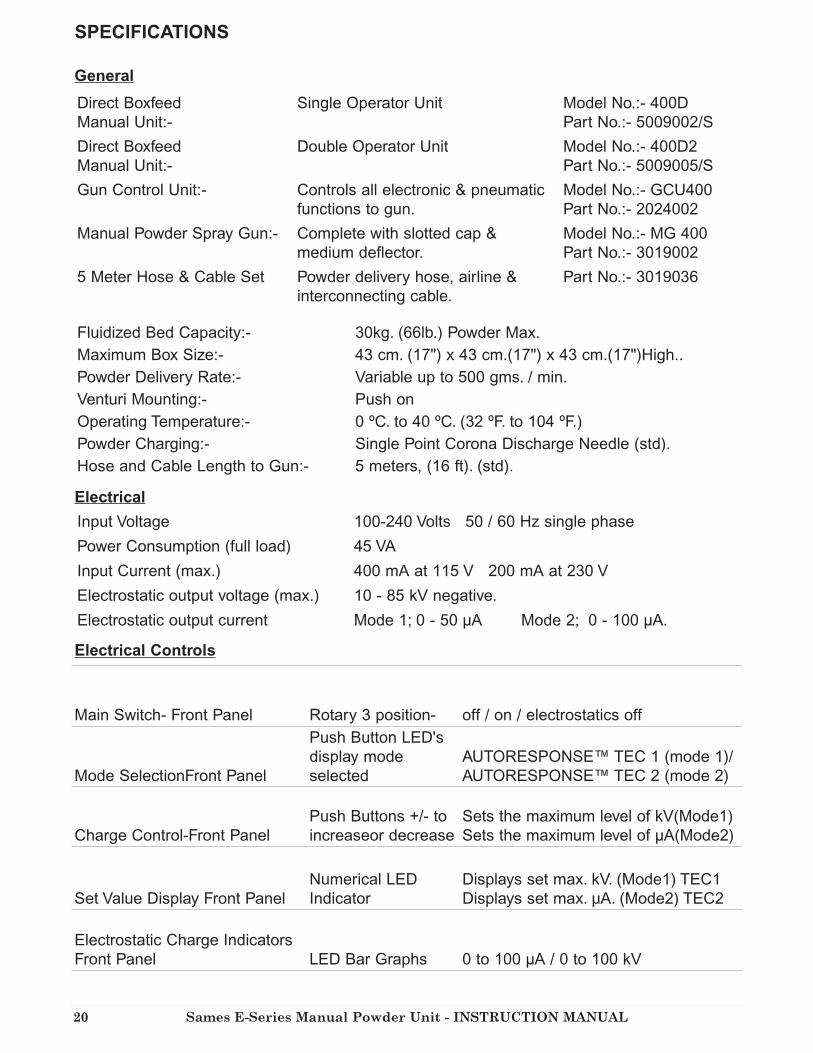
SPECIFICATIONS
General
Electrical
Electrical Controls
Direct Boxfeed
Manual Unit:-
Single Operator Unit Model No.:- 400D
Part No.:- 5009002/S
Direct Boxfeed
Manual Unit:-
Double Operator Unit Model No.:- 400D2
Part No.:- 5009005/S
Gun Control Unit:- Controls all electronic & pneumatic
functions to gun.
Model No.:- GCU400
Part No.:- 2024002
Manual Powder Spray Gun:- Complete with slotted cap &
medium deflector.
Model No.:- MG 400
Part No.:- 3019002
5 Meter Hose & Cable Set Powder delivery hose, airline &
interconnecting cable.
Part No.:- 3019036
Fluidized Bed Capacity:- 30kg. (66lb.) Powder Max.
Maximum Box Size:- 43 cm. (17") x 43 cm.(17") x 43 cm.(17")High..
Powder Delivery Rate:- Variable up to 500 gms. / min.
Venturi Mounting:- Push on
Operating Temperature:- 0 ºC. to 40 ºC. (32 ºF. to 104 ºF.)
Powder Charging:- Single Point Corona Discharge Needle (std).
Hose and Cable Length to Gun:- 5 meters, (16 ft). (std).
Input Voltage 100-240 Volts 50 / 60 Hz single phase
Power Consumption (full load) 45 VA
Input Current (max.) 400 mA at 115 V 200 mA at 230 V
Electrostatic output voltage (max.) 10 - 85 kV negative.
Electrostatic output current Mode 1; 0 - 50 µA Mode 2; 0 - 100 µA.
Main Switch- Front Panel Rotary 3 position- off / on / electrostatics off
Mode SelectionFront Panel
Push Button LED's
display mode
selected
AUTORESPONSE™ TEC 1 (mode 1)/
AUTORESPONSE™ TEC 2 (mode 2)
Charge Control-Front Panel
Push Buttons +/- to
increaseor decrease
Sets the maximum level of kV(Mode1)
Sets the maximum level of µA(Mode2)
Set Value Display Front Panel
Numerical LED
Indicator
Displays set max. kV. (Mode1) TEC1
Displays set max. µA. (Mode2) TEC2
Electrostatic Charge Indicators
Front Panel LED Bar Graphs 0 to 100 µA / 0 to 100 kV

Sames E-Series Manual Powder Unit - INSTRUCTION MANUAL 21
Manual gun connected LED Indicator at "T"
when triggered
Unit is triggered by micro-switch in Hand Gun
or other remote triggering device when main
switch is turned to On position.(1)Unit is
triggered by micro-switch in Hand Gun or
other remote triggering device without
electrostatics when main switch is turned to
E'statics Off position.
Manual Gun Detection -- Unit automatically detects when gun is connected
Main Input Via connector on rear panel.
Main Output Socket Non switched 6A max.- may be used to connect
additional control units.
Trigger Switch - Hand Gun Microswitch in hand gun- connected through plug and
socket on rear of control unit.
Circuit Protection
Miniature Circuit Breakers: Main Input
Main Output
0.6A
6A
Input Air Pressure
Input Air Conditioning
Air Consumption (Nominal)
Input Connection
100 psi (7.0 bar) max.
Oil free to 0.1 p.p.m. and dry to 1.3 g/m3.
9.0 cfm. ( 15.0 m3/h )
¼" bsp male air fitting.
Pneumatic Controls
Pressure regulators and gauges
These control the air supply pressure to the following :
i) Powder Delivery 60 psi (4 bar) venturi jet; controls delivery of powder from
the venturi to the gun
(ii) Dilution Ratio 30 psi (2 bar) venturi dilution; controls the mixture ratio of
powder to air from the venturi to the gun
(iii) Gun-Forward Air 30 psi (2 bar) air supply to the gun; prevents powder
buid-up on the face of deflectors and inside
the nozzle
Auxiliary Output
Maintained unregulated output for connection of ancillary equipment, ie. Second control unit
or an air clean down gun. Connection 6mm. push in fitting. Supplied fitted with blanking plug.
Weights & Dimensions
Complete Unit 400D
Packaged Unit weight/dims. 88.5lbs / 40kg 42”H x 21”W x 29”D
107cm x 54cm x 74cm

Sames E-Series Manual Powder Unit - INSTRUCTION MANUAL22
ASSEMBLY INSTRUCTIONS
WARNING: THIS EQUIPMENT MUST BE GROUNDED
1. Carefully remove units and components from packaging, and check contents against packing list.
(Placed in the box)
2. Secure the Gun Control Unit to the vertical column with the 2-off M6 x 10 socket cap head screws
and lock washers as shown on page 23 (parts 12,13,14), using the long 5mm hex. key provided.
3. Connect the four un-connected airlines to the air fittings on the rear of the Gun Control Unit as
follows:-
NOTE:- Diagrams at the rear of this manual indicate the relevant connectors and fittings.
a) RED airline from the Venturi Jet to the bottom left hand air fitting.
b) BLUE airline from the Venturi Dilution Port to the centre left hand air fitting
c) CLEAR airline from Vibrator to the 'GUN / F. BED or VIBRATOR AIR SUPPLY OUTPUT'
fitting.
d) BLACK airline from the gun services assembly to the top left hand air fitting.
4. Connect the large BLACK airline (8mm.od.) to the centre right hand air fitting on the rear of the
gun control unit.
5. Insert the suction tube through the bottom spigot on the front bracket of the articulated arm until
it latches into position,
6. Ensure that the three airlines which exit the front of the articulated arm are connected as follows:-
a) RED airline to POWDER DELIVERY air fitting at the top rear of the venturi (The sealing
washer of this fitting is red).
b) BLUE airline to POWDER DILUTION air fitting at the top centre of the venturi. (The
sealing washer of this fitting is blue).
c) BLACK Airline to the FLUIDIZING PAD quick release air fitting on the top of the venturi
mounting bracket.
7. Secure the Gun Hook to the side of the Gun Control Unit using the M6 x 50 socket cap head screw
as shown.
8. Remove the hand gun from the carton. The gun is supplied fitted with a five meter hose and cable
set comprising of :-
a) 1-off supply / trigger cable.
b) 1-off powder hose.
c) 1-off 6 mm air line.
9. Connect the round supply / trigger cable connector to the plug on the base of the gun handle,
connect the black airline to the airline tail on the base of the gun handle and finally push the
powder hose fully onto the spigot on the base of the handle.
10. The other end of the gun service assembly should be connected as follows:- The square 5 way
electrical connector to the lower right connector on the rear of the control panel and secure using
the metal latch. The 12mm. bore powder hose to the powder spigot on the venturi. The black air
line to the top left hand air fitting on the rear of the gun control unit.
11. Connect a suitable airline to the 1/4" BSPMP air connection of the ball valve mounted on the side of
the chassis.
12. If not already fitted, fit the spray nozzle to the gun by removing the large front retaining nut,
inserting the electrode assembly into the nut, point first, and replacing on the barrel. Fit either the
slotted cap over the front end of the nozzle, or the medium size deflector onto the stem of the
electrode.

Sames E-Series Manual Powder Unit - INSTRUCTION MANUAL 23
13. With the main switch in the off position, connect the 4-way main connector to the top left connector
on the rear panel of the gun control unit and secure using the metal latch..
14. IMPORTANT:- When fitting a plug to the main lead, it is essential that it contains an
grounding/grounding contact that this is connected. Under no circumstances should this equipment
be connected to a main supply which does not include an grounding/grounding wire and contacts.
e.g. 2 wire extension leads as used for some domestic equipment MUST NOT BE USED.
NOTE:- The cable color coding and connector pins used for the Gun Control Unit and its supplied
cable are as follows:-
NOTE:- The terminal connections used on the main connectors on the rear panel of the unit
coincide with the terminal connections used on the cable connectors.
NOTE:- For United States and Canada Installations see below:-
As the colors of the main lead of this appliance may not correspond with the colored markings
identifying the terminals in your plug, proceed as follows:-
The wire which is colored GREEN and YELLOW must be connected to the terminal in the plug
which is marked with the letter E or by the earth symbol , or colored green or green and yellow.
The wire which is colored WHITE must be connected to the terminal which is marked with the
letter N or colored silver. The wire which is colored BLACK must be connected to the terminal
which is marked with the letter L or colored red.
NOTE:- The method of disconnection from the main electrical supply is by removal of the plug on
the main lead from its respective supply socket.
NOTE:- If the system is to be permanently connected to main wiring then the switch used to
disconnect the unit from the supply voltage must disconnect all poles and have a contact
separation of at least 3 mm.
The unit is now ready for use.
Pole Designation U.S.A U.K. Pin Connection
Live / Hot L Black Brown Gold / 1
Neutral N White Blue Silver / 3
Earth / Ground E Green Green w/ Yellow Green / E

Sames E-Series Manual Powder Unit - INSTRUCTION MANUAL24
SET UP PROCEDURE
1. 1. Ensure that all switches are in the OFF position and that all pressure regulators are closed,
(the knobs should be turned fully counter-clockwise). The knobs of the pressure regulators are
released by pulling outward and locked by pressing inward.
2. Lift the articulated arm to it's maximum height and push down on the front of the venturi
mounting bracket to lock the arm into a parked position.
3. Place an open box of powder onto the unit base
4. Lift the front of the venturi mounting bracket and lower the articulated arm and suction tube so
that the fluidized suction head is lowered onto the powder The tube will enter the powder during
operation and will "burrow" into the powder towards the front corner of the box.
5. Turn on the 'MAIN ELECTRICAL' switch of the control unit to the second position marked :-
The numerical display of set value and the mode indicator will illuminate. The electrostatic output
will be disabled.
NOTE:- Diagrams in the appendix indicate the various switches, regulators, etc.
6. With the spray gun pointing into an extracted spray booth, operate the trigger of the gun. A red
LED will illuminate next to the `T` symbol on the display.
7. With the trigger still operated open the air regulator on the side of the chassis to approximately 30
psi. to actuate the vibrator.
8. With the trigger still pressed, open the flow regulator on the side of the chassis by turning the knob
counter-clockwise until a slight disturbance of powder is noticed around the fluidizing pad at the
bottom of the suction tube. This air supply should be kept to a minimum consistent with smooth
powder flow to prevent powder from being ejected from the box into the surrounding air.
NOTE:- The flow regulator has a lock nut which may be used to set the flow setting.
With the trigger still pressed, open the left hand pressure regulator on the control panel (GUN
AIR) to approximately 0.35 bar (5 psi.) This helps to prevent any powder build up at the front of
the nozzle.
9. With the trigger still pressed, open the center pressure regulator on the control panel (DILUTION
AIR) to approximately 0.5 bar (7 psi.) and then open the right hand pressure regulator (POWDER
DELIVERY AIR) to give the required powder output. A good starting point is 1 bar (15 psi.)
NOTE:- It is good practice to always operate the powder control regulator last to avoid possible
powder contaminating air lines.
10. Check that all regulators are operating when the trigger is pulled and adjust pressures as
necessary to ensure an even flow of the desired quantity of powder from the gun. The powder in
the box should be seen to be moving towards the suction tube when the vibrator is operating and
powder is being sprayed.The air pressure required for the vibrator may depend upon the quantity,
the type and condition of the powder being used.
11. Having set the volume of powder required from the gun, if there is a tendency for the powder flow
to surge, this can normally be eliminated by adjusting the POWDER DILUTION AIR pressure. If,
however, the fluidization of the powder is too violent, difficulty may be experienced in eliminating
surging and erratic powder delivery.
NOTE:- If the powder in the box is damp, it may not be possible to achieve a smooth, even powder
flow from the gun.

Sames E-Series Manual Powder Unit - INSTRUCTION MANUAL 25
12. Turn the main switch on the front panel to the first position, This will enable the electrostatics
when the trigger is operated. Press the `MODE` push button switch to set the operating mode in
AutoResponse™ TEC1 with the green light illuminated. This will enable the setting of Maximum
discharge voltage (kV) using the + and - pushbuttons between 10 to 85kV. The setting in kV. is
displayed on the numerical display above the +/- buttons.
13. With the gun pointing into an extracted spray booth, operate the trigger and to see the actual
discharge voltage and current displayed on the bar graphs. Voltage is displayed in green and
current is displayed in amber. The maximum discharge current in AutoResponse™ TEC1 mode is
50 µA.
NOTE:- The discharge current and voltage is dependent on the proximity of the spray gun needle
to earth. When setting the maximum discharge potential the spray gun discharge needle should be
placed approximately 100cm from earth.
14. With the trigger still pressed, press the `MODE` push button switch to set the operating mode in
AutoResponse™ TEC2 with the amber light illuminated. This will enable the setting of Maximum
discharge current (µA) using the + and - pushbuttons between 5 to 100uA. The setting in uA. is
displayed on the numerical display above the +/- buttons.
15. Operating in AutoResponse™ TEC 1 mode:-
The maximum discharge potential (kV) required will depend largely on the object to be coated,
although such parameters as environmental conditions may affect the required settings. Generally,
intricate objects or components with difficult return edges, internal corners or deep recesses, or
welded tubular structures may benefit from low discharge potentials of 40-60 kV whereas large
simple panels may benefit from higher potentials of 60-70 kV. It will be found that aluminum
parts require lower settings than steel parts and that re-coating of items which have already been
powder coated may require very low settings such as 30-40 kV. in order to prevent back ionization.
Thicker coatings may often be applied with lower output voltages, whereas higher discharge
potentials give more of a self limiting effect for thinner coatings, but care must be taken to avoid
surface disruptions and back ionization.
16. Operating in AutoResponse™ TEC 2 mode:-
The discharge current (µA) required will depend largely on the powder being used and the quality
of finish required.
Metallic powders can cause problems for electrostatic spray guns due to free metallic particles
creating conduction paths within the gun or the external powder clouds causing loss of charge.
Although the majority of metallic powders have encapsulated metallic particles and cause no
problems, higher discharge currents may be required in order to overcome the leakage current
where un-bonded metallic powders are used. The discharge current in AutoResponse™ TEC2 mode
may be adjusted from 5 up to 100 µA. in order to overcome the leakage current and still generate a
corona discharge to charge the powder
If lower discharge currents are used, 30µA, the operational distance of the AutoResponse™ TEC
fold back characteristic will be extended to 600 mm. This may be of more use in automatic
installations than for manual spray guns.

Sames E-Series Manual Powder Unit - INSTRUCTION MANUAL26
GENERAL NOTE:-
An approved mask should always be worn when spraying.
GENERAL OBSERVATIONS:-
It is essential that all substrates and hooks are clean and that there is a good earth / ground to the
work-piece to ensure maximum powder attraction.
Powder spraying is best performed by slow motions of the spray gun as opposed to the faster gun
movements often associated with liquid paint spraying. Higher powder emissions do not
necessarily mean faster coating or better penetration into corners and recesses. In practice it can
often cause the opposite effect and produces products with a poor finish.
Similarly, high electrostatic discharge currents or voltages do not necessarily mean faster or more
efficient coating. Again, in practice, they can cause the opposite effect and produce products with a
poor finish.
RECOATING:-
The "Total Energy Control" charging system permits exceptional ease of recoating products which
have previously been coated and cured. To take advantage of this ability it is necessary for the
operator to use a different technique to that usually employed for recoating.
FOR BEST RESULTS:-
Instead of turning down the voltage control to very low levels and pulling the gun away from the
product, the charge control may be left at maximum and the gun may be taken close to the product
surface, this also helps when penetrating recesses and corners. In some instances it may be
necessary to reduce the charge control for better results.

Sames E-Series Manual Powder Unit - INSTRUCTION MANUAL 27
Color Changing
In order to prevent contamination of the product from a previous color, it is
essential to remove all traces of the previously sprayed powder from the
application equipment. i.e. Powder container, suction tubes, Venturies, Powder
hoses and Spray guns. Also any other surfaces where powder may become
dislodged and cause contamination of the product or new powder. If the powder is
to be reclaimed, then the spray booth, ductwork and recovery equipment must also
be thoroughly cleaned.
IMPORTANT: WHENEVER COMPRESSED AIR IS USED FOR CLEANING
EQUIPMENT. THIS OPERATION MUST BE CARRIED OUT IN AN
EXTRACTED SPRAYBOOTH. AN APPROVED MASK AND EYE
PROTECTION SHOULD ALWAYS BE WORN WHEN USING A
COMPRESSED AIR BLOW DOWN GUN.
1. Lift the articulated arm to it's maximum height and push down on the front of the
venturi mounting bracket to lock the arm into a parked position
2. Remove the box of powder from the unit base
3. Turn the main switch of the gun control unit to the OFF position and discharge
the gun by touching the corona needle to a good earth
4. Remove the venturi from the suction tube spigot and disconnect the powder hose
and air connectors from the venturi. Remove the powder tail fitting complete with
the PTFE insert from the venturi body and using clean, dry compressed air from a
blow gun, clean the venturi components thoroughly inside and outside.
5. Refit the hose tail and insert to the venturi body. ALWAYS CHECK THE
CONDITION OF THE PTFE INSERT FOR SIGNS OF EXCESSIVE WEAR AND
REPLACE AS NECESSARY.
6. Disconnect the fluidizing air connector at the underside of the venturi bracket,
squeeze the gray plastic retaining clip and remove the suction tube from the
bottom of the venturi mounting bracket.
7. Using clean, dry compressed air from a blow gun, blow through the suction tube
and clean the outside.
8. Remove the powder hose from the gun and purge the inside of the hose with
compressed air.
9. Remove the nozzle from the gun and clean internally and externally with
compressed air. Clean the rest of the gun in the same way.
10. Refit the nozzle and powder hose to the gun.
11. Replace the suction tube up through the venturi mounting spigot. Re-connect the
powder hose to the venturi, and the airlines i.e. red airline to fitting with red
washer and blue airline to fitting with blue washer, then refit the venturi back on
to suction tube.
12. Clean off any excess powder or contamination from base plate and frame.
13. Place new box of powder onto unit base.
14. Lower suction tube into the new powder.

Sames E-Series Manual Powder Unit - INSTRUCTION MANUAL28
DO's and DON'TS
DO's
1. Ensure that the equipment is operated by trained personnel only.
2. Ensure that the equipment is serviced regularly by qualified personnel. All repairs and
maintenance shall be carried out by qualified personnel only, in accordance with the
manufacturers instructions. Repairs must be carried out at the recommendation of the
operator when faults or defects are detected. Repairs must not be performed in hazardous
areas and must not compromise safety standards. (Any repairs or maintenance carried
out by unqualified personnel will invalidate any warranty on the equipment).
3. Ensure that the operator is correctly grounded. If overalls are worn, they should be anti-
static or non-insulating. If gloves are worn, they should be anti-static or non-insulating. If
this is not possible, gloves with the palms removed may be used. Footwear intended for
use by operators shall be anti-static or non-insulating and shall comply with the
requirements of ISO 2251 / BS 5451 or equivalent. Shoes with leather soles are usually
adequate.
4. Ensure that the operator wears suitable respiratory equipment and or protective clothing.
All personnel working in a powder-laden atmosphere should wear similar equipment.
5. Ensure that the operator wears suitable eye protection e.g. goggles or a visor (in addition
to a respiratory mask) when using a compressed air clean down gun as particles in the
airstream can damage eyes.
6. Avoid skin contact with powders where possible as some powders may cause skin
irritation.
7. Wash hands and face after work and prior to eating or drinking.
8. Keep floors and equipment within 5 meters of the spray area clean using a suitable
industrial vacuum cleaner.
9. Keep light fittings and all other electrical equipment clean.
10. Regularly check the effectiveness of dust/powder collectors and extraction filters and that
recycled air is clean.
11. Regularly check the ground/earth of electrical equipment and manually operated spray
guns.
12. Regularly check the grounding/grounding of all conductive electrical enclosures and all
conductive structures such as floors, walls, ceilings, fences, conveyors, powder containers
etc. within the vicinity of the spray area. These shall be connected to the ground/earth
terminal of the high voltage generator to the protective earth system of the electrical
supply. Electrostatic grounding should comply with EN 50053.
13. Ensure that all hooks and work pieces are adequately grounded. Each work-piece shall
have a resistance to earth of not greater than 1 Mohm. This resistance shall be checked
regularly.
14. Ensure that correct cleaning procedures are followed. See "Changing Color and End of
Shift Cleaning Procedures"
15. Ensure that powders are processed in compliance with the powder manufacturers
instructions. Special care should be taken with powders containing metallic pigments.
16. Regularly check the compressed air supply to ensure that it is clean and dry.

Sames E-Series Manual Powder Unit - INSTRUCTION MANUAL 29
DO's and DON'TS
DON'TS
1. The operator must not wear insulating gloves, clothing or footwear.
2. Do not smoke in areas where powder coating is being carried out or in areas where
powder is stored.
3. Do not eat or drink in areas where powder coating is being carried out or in dust-laden
atmospheres.
4. Do not spray into areas which are not properly extracted. The direction of airflow should
always be from behind the operator. It is recommended that airflow velocities over the
face area of a booth opening should be in excess of 98 ft/min (0.5 meters/sec).
5. Do not use compressed air for cleaning skin and clothing as it can penetrate the skin
causing embolisms. Use a suitable industrial vacuum cleaner for clothing and wash skin
with water.
6. Do not point compressed air clean down guns towards body orifices such as mouth, ears
etc.
7. Do not enter spray booths when in operation.
8. Do not operate fluidized beds without connecting a suitable vent hose from its lid to an
extracted area such as a spray booth.
NOTE: The workplace must be kept tidy and well organized to reduce the risk of
accidents. Good illumination, protection from any damp environment and correct storage
of materials will assist the operator to maintain concentration and an awareness of
potential hazards.
NOTE: Before starting to clean the spray gun or carrying out any other work in the
spraying area, the high voltage supply shall be switched off in such a manner that it
cannot be re-energized by operating the trigger of the spray gun.

Sames E-Series Manual Powder Unit - INSTRUCTION MANUAL30
Check the trigger connections at the gun and on the bottom panel of the
control unit.
Check that the trigger switch in the gun is operating. Depress the trigger and
an audible click should be heard if the trigger switch is operating and a red
light should illuminate next to the letter `T` on the control panel.
Check air supply to unit, and that the ball valve is turned on.
Check that the powder box is not empty.
Check that the internal solenoid valve is operating by depressing gun trigger
when an audible click should be heard and a red light should illuminate next
to the letter `T` on the control panel. If it is not, check the trigger connections
at the gun and on the rear panel of the control unit.
Check for kinked or blocked powder hose.
Check for blockage in suction tube, venturi body and gun.
Check that the level of vibration and/or fluidization air is adequate to keep the
powder flowing to the suction point.
Check that there is sufficient powder in the box.
Check ratio of dilution air to powder air and adjust if necessary.
Check for any kinks or partial blockages in the powder hose, venturi suction
tube and body, or gun. Blockages in powder paths may be caused by damp
powder if the air supply contains more than the permitted level of moisture.
Check that the venturi body is located securely and sealing at the top of the
suction tube.
Check condition of PTFE insert in venturi for signs of wear - replace as
necessary.
Check that the powder is not damp. If it is, it may be difficult to fluidize
evenly and lumps may form in the powder causing partial blockages and
'spitting' from the nozzle of the gun. Powder may become damp if left for long
periods in an open fluid bed or if the air supply contains more than the
permitted level of moisture. Refer to the Pneumatic Data in the specifications.
Check that the level of vibration and/or fluidization air is adequate to keep the
powder flowing to the suction point.
Check that main switch is set to the first position marked 1. The green and
yellow LED bar graphs should be illuminated to show the level of electrostatic
discharge from the spray gun
Check the setting of the charge control is at a sufficient level to charge the powder
effectively and that an electrostatic charge is present at the discharge electrode
needle of the gun.
Check that the work-piece is properly grounded/grounded.
Check that the compressed air supply is clean and dry. Dirt and moisture trapped
inside the gun may cause a loss of electrostatic charge to earth, if this is occurring
the units warranty may be invalidated.
FAULT FINDING
UN
IT W
ILL
NO
T
OP
ER
AT
E
(LE
D's
lit
)
NO
PO
WD
ER
DE
LIV
ER
YP
OW
DE
R D
EL
IVE
RY
IN
TE
RM
IT-T
EN
T O
R
SU
RG
ING
PO
WD
ER
DO
ES
NO
T
AD
HE
RE
TO
WO
RK
-PIE
CE
Check that main connector is fitted to rear panel of control unit.
Check that unit is connected to a suitable main electrical supply and is switched
on.
Check that miniature circuit breaker (automatic fuses) on the rear panel of the
control unit have not tripped. If one or more has, then press to reset. If it trips
again, switch off unit and refer to an authorized distributor or service agent.-UN
IT W
ILL
NO
T
OP
ER
AT
E(N
o
LE
D's
wil
l
illu
min
ate
)

Sames E-Series Manual Powder Unit - INSTRUCTION MANUAL 31
Application equipment inadequately cleaned after using previous
powder.
Airborne powder of different type within a contaminated spraybooth, or
sucked in from dirty surroundings.
Reclaimed powder contaminated with other powders from within the
reclaim system e.g. ductwork, cyclone, booth etc.
Airborne contamination within the oven.
Dust or dirt dislodged from hooks or conveyor.
Dusty environment before or after coating.
Dirty or contaminated powder.
Dirty or contaminated substrate (work-piece)
Rusty substrate
Dusty environment before or after coating.
Dust or dirt in oven.
Dust or dirt dislodged from hooks or conveyor.
Applied coating is too thick.
Incorrect cure cycle and/or temperature.
Inferior quality of powder.
Contamination of substrate.
Contamination of powder.
Contamination of compressed air supply.
Poor cleaning of substrate e.g.. trapped oils or solvents.
Wet components e.g.. water trapped in corners or joints.
Contamination of powder.
Contamination of substrate.
Porous substrate e.g. expansion or air or solvents from porosity or
cavities in castings during curing cycle.Pre-heating of the work-piece
may help to overcome this.
Excessive electrostatic charge applied to the powder.To overcome, reduce
the discharge current and / or increase the spraying distance.
Rusty substrate.
Contamination of substrate, powder, air supply or from dirty
surroundings.
Excessive moisture in compressed air supply. Refer to pneumatic data
in specifications.
NOTE:- Contamination may be caused by airborne vapor such as wet paint, airline or
conveyor oil or stripping facilities.
Silicones and acrylic paints are the worst offenders and can contaminate the powder
and/or substrate.
DEFECTS ON FINISHED PRODUCT
CO
NT
AM
INA
TIO
N O
F
SU
RF
AC
E W
ITH
SP
EC
KS
OF
OT
HE
R
CO
LO
RS
LU
MP
S O
R
PR
OT
RU
SIO
NS
ON
SU
RF
AC
E
HE
AV
Y
"OR
AN
GE
PE
EL
"
FIS
H
EY
ES
CR
AT
ER
S
AN
D
VO
IDS
PIN
-HO
LIN
G A
ND
BU
BB
LE
S

Sames E-Series Manual Powder Unit - INSTRUCTION MANUAL32
AUTORESPONSE™ TEC (TOTAL ENERGY CONTROL)
"AutoResponse™ Total Energy Control" is a patented system developed by EXEL INDUSTRIAL
to automatically control the electrostatic charging energy of a spray gun to optimum levels of
both current and voltage subject to the distance between the spray gun and the work-piece to be
coated.
The spray material is not charged directly by the spray gun, but by the "charged air through
which it passes between the spray gun and the work-piece. The charge density of the ionized air
is a function of the discharge current from the gun. The smaller the distance between the gun
and the work-piece, the lower the volume of the air through which the powder travels, and the
lower will be the discharge current required for the same charge density and vice versa. A
reduction of discharge current is accompanied by a reduction in discharge voltage, resulting in a
significantly lower discharge energy.
By automatically adjusting the total discharge energy in this way, the output is controlled from
full discharge when away from the work-piece to minimal output when very close, but with the
same high charging efficiency regardless of distance. A significant advantage of this technique is
the ability to take the gun in close to a product to "place" the powder into hard to coat and
Faraday Cage areas without the normal problems of overcharging the surface creating back
ionization pinholes, orange peel, or blowing the powder off.
AutoResponse™ Total Energy Control is not new to Exel Industrial and is well proven and
accepted for its coating benefits and ease of use. The original mode (AutoResponse™ TEC 1) with
a 50 uA. threshold and operator adjustment of max kV is suitable for the majority of standard
powders and applications is now enhanced by a second operating mode (AutoResponse™ TEC 2).
This gives the operator adjustment over the max. output current up to a 100 µA. threshold.
This will help with the spraying of some of the more difficult metallic powders. Alternatively, if
the discharge current threshold is turned down to say 30 µA. the active operating range of
AutoResponse™ TEC may be increased to say 500mm. which may be very useful for automatic
applications where products have large variations in their profiles.
When powering up a control unit, the last operating mode and settings will automatically be
recalled. When switching between operating modes, the last settings of the alternative mode will
automatically be recalled. Adjustment to max. kV. (AutoResponse™ TEC 1) or max. µA.
(AutoResponse™ TEC 2) is made using the + and - buttons and the set value is indicated on the
numerical display. The discharge voltage and current are indicated on the LED bar graphs.

Sames E-Series Manual Powder Unit - INSTRUCTION MANUAL 33
GC
U-4
00 G
un
Co
ntr
ol
Un
it
Fro
nt
Pa
nel
Sy
mb
ols
Ex
pla
na
tio
n
Illu
stra
tion
No.
6000197
GC
U-4
00 G
un
Co
ntr
ol
Un
it
Rea
r P
an
el
Sy
mb
ols
Ex
pla
na
tio
n
Illu
stra
tion
No.
6000198

Sames E-Series Manual Powder Unit - INSTRUCTION MANUAL34
400H
Flu
idb
ed
Un
it
Sin
gle
Op
era
tor,
Gen
era
l A
ssem
bly
Pa
rt
No
. 5008002
/S
Illu
stra
tion
No.
6000219

Sames E-Series Manual Powder Unit - INSTRUCTION MANUAL 35
Single Fluidbed, Piping Diagram
Illustration No. 6000220
1 2024002 Gun Control Unit - GCU 400 1
2 3019002 Manual Powder Gun - MG 400 1
3 5008004 Chassis Assy, 400 Boxfeed 1
4 5008003 Fluidbed Body 50L 1
5 5000038 Main Lead Assy 1
6 2095002 Venturi Assy, 400 Series 1
7 5008006 Suction Tube Assembly (NS) 1
8 3019036 Hose & Cable Set, 5M 1
9 5008030 Warning Label (NS) 1
10
11 5009024 Gun Mounting Pillar 1
12 9000657 Screw, M6 x 10 Skt, Cap Head 2
13 9000840 Washer, M6, Crinkle 2
14 9001914 M5 Long Handle Allen Key 1
15 7000001 M4 Allen Key (NS) 1
16 7000000 M3 Allen Key (NS) 1
Item Part Number Description Quantity
400 Series Fluidized Hopper Unit, Single Operator, General Assembly Parts List
(NS) - Not Shown on this illustration