e-series e2860, e5760, and de460c shelves installation and
TRANSCRIPT
Complete System Setup and Configuration | 4
1
NetApp Inc.
1395 Crossman Ave.Sunnyvale CA, 94089 U.S.A.
Telephone: +1 (408) 822-6000Fax: +1 (408) 822-4501Support Telephone: +1 (888) 463-8277Comments: [email protected]
Copyright © 2020NetApp Inc.All rights reserved.
Prepare for Installation | 1
In the box
You provide
Resources
Create an account and register your hardware at mysupport.netapp.com.Inventory cables and make note of the quantity.Confirm that your location provides 240V AC power.
E-Series E2860, E5760and DE460C ShelvesInstallation and Setup Instructions
Shelf, bezel, andrackmount hardware
Shelf handles
A supported browserfor the management
software
I/O cablesif ordered
Ethernet cablesif ordered
SAS cablesincluded only withthe drive shelves
Power cablestwo for each shelf
× 4
Phillips №2 screwdriver,flashlight, and ESD strap
4U rack space
4U
A 19 in. (48.30 cm)rack to fit 4U shelves of thefollowing dimensions:
Max Weight: 250 lb. (113 kg)Depth: 38.25 in (97.16 cm)Width: 17.66 in. (44.86 cm)Height: 6.87 in. (17.46 cm)
210-
0676
9+C0
Prepare for Installation Install Hardware Connect the Cables Complete System Setupand Configuration
4321
№2
Hardware Universehwu.netapp.com
Quick Connect Utilitymysupport.netapp.com/quickconnect
NetApp Interoperability Matrixmysupport.netapp.com/matrix
Cabling Guidedocs.netapp.com/ess-11/topic/com.netapp.doc.e-hw-cabling/home.html
E-Series Documentation Centerhttp://docs.netapp.com/ess-11/index.jsp
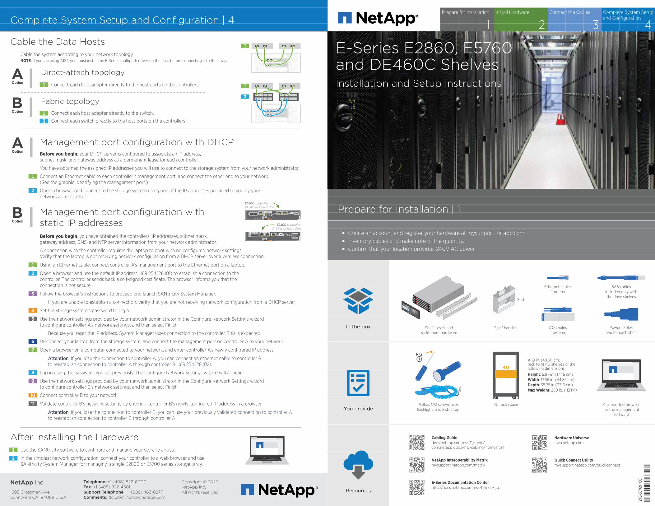
Cable the Data HostsCable the system according to your network topology. NOTE: If you are using AIX®, you must install the E-Series multipath driver on the host before connecting it to the array.
Direct-attach topologyOption Connect each host adapter directly to the host ports on the controllers.1
Fabric topologyOption Connect each host adapter directly to the switch.
Connect each switch directly to the host ports on the controllers.
12
After Installing the HardwareUse the SANtricity software to configure and manage your storage arrays.1
In the simplest network configuration, connect your controller to a web browser and use SANtricity System Manager for managing a single E2800 or E5700 series storage array.
2
Before you begin, your DHCP server is configured to associate an IP address, subnet mask, and gateway address as a permanent lease for each controller.
You have obtained the assigned IP addresses you will use to connect to the storage system from your network administrator.
Connect an Ethernet cable to each controller’s management port, and connect the other end to your network.(See the graphic identifying the management port.)
Open a browser and connect to the storage system using one of the IP addresses provided to you by yournetwork administrator.
Management port configuration with DHCP
Management port configuration withstatic IP addressesBefore you begin, you have obtained the controllers’ IP addresses, subnet mask, gateway address, DNS, and NTP server information from your network administrator.
A connection with the controller requires the laptop to boot with no configured network settings.Verify that the laptop is not receiving network configuration from a DHCP server over a wireless connection.
Using an Ethernet cable, connect controller A’s management port to the Ethernet port on a laptop.
Open a browser and use the default IP address (169.254.128.101) to establish a connection to thecontroller. The controller sends back a self-signed certificate. The browser informs you that theconnection is not secure.
If you are unable to establish a connection, verify that you are not receiving network configuration from a DHCP server.
Because you reset the IP address, System Manager loses connection to the controller. This is expected.
Set the storage system’s password to login.
Follow the browser’s instructions to proceed and launch SANtricity System Manager.
Use the network settings provided by your network administrator in the Configure Network Settings wizardto configure controller A’s network settings, and then select Finish.
Disconnect your laptop from the storage system, and connect the management port on controller A to your network.
Open a browser on a computer connected to your network, and enter controller A’s newly configured IP address.
Attention: If you lose the connection to controller A, you can connect an ethernet cable to controller Bto reestablish connection to controller A through controller B (169.254.128.102).
Log in using the password you set previously. The Configure Network Settings wizard will appear.
Use the network settings provided by your network administrator in the Configure Network Settings wizardto configure controller B’s network settings, and then select Finish.
Connect controller B to your network.
Validate controller B’s network settings by entering controller B’s newly configured IP address in a browser.
Attention: If you lose the connection to controller B, you can use your previously validated connection to controller Ato reestablish connection to controller B through controller A.
Option
Option
1
2
1
3
4
5
6
7
8
9
10
11
2
E5700 controller P1 Management Port
0a 0bP1 P2
EXP1 EXP2
E2800 controller P1 Management Port
Install Hardware | 2
Unpack the HardwareUnpack the contents and inventory the contained hardware againstthe packing slip. Read through all the instructions before proceeding.
Install the RailsSee the enclosed document,Installing SuperRail into a four-post rack for instructions on how to install the rails.
NOTE: For square hole cabinets, you must firstinstall the provided cage nuts to secure the frontand rear of the shelf with screws.
Install the Shelf
Secure the ShelfInsert screws into the first and third holes fromthe top of the shelf on both sides to secure it tothe front of the cabinet.
Place two back brackets on each side of theupper rear section of the shelf. Insert screws into the first and third holes of each bracket to secure the back of the cabinet.
Install the Drives
Starting at the front left slot of the top drawer, install each drive by gentlypositioning into the drive slot and lowering the raised drive handle until itclicks into place.
Wrap the strap end of the ESD wristband around your wrist, and secure the clip end to a metal ground to prevent static discharges.
NOTE: If you are installing fewer than 60 drives, if you havesolid-state drives (SSDs), or if your drives have di�erent capacities:
Maintain a minimum of 20 drives per shelf. Install drives in the front four slots in each drawer first, for adequate airflow for cooling.
Distribute any remaining drives across the drawers. If possible, install an equalnumber of each type of drive in each drawer to allow for the creation of Drawer Loss Protected volume groups or disk pools.
Distribute any SSDs evenly across the drawers.
Supporting the shelf from the bottom, slide it into thecabinet. If the lift handles are used, remove them one set at a time as the shelf slides into the cabinet.To remove the handles, pull back on the release latch, push down, then pull away from the shelf.
If lifting the shelf by hand, attach the four lift handles.Push up on each handle until it clicks into place.
4Person
Team Lift
CAUTION: An empty shelf weighs approximately132 lb (60 kg). A mechanized lift or four people using lift handles are required to safely move an empty shelf.
1
2
1
2
1
2
Carefully slide the drawer back in by pushing the centerand gently closing both latches.
3
Attach the front bezel.4
Connect the Cables | 3
0a 0bP1 P2
EXP1 EXP20c 0d 0f0e
0a 0bP1 P2
EXP1 EXP20c 0d 0f0e
21 43
21 43
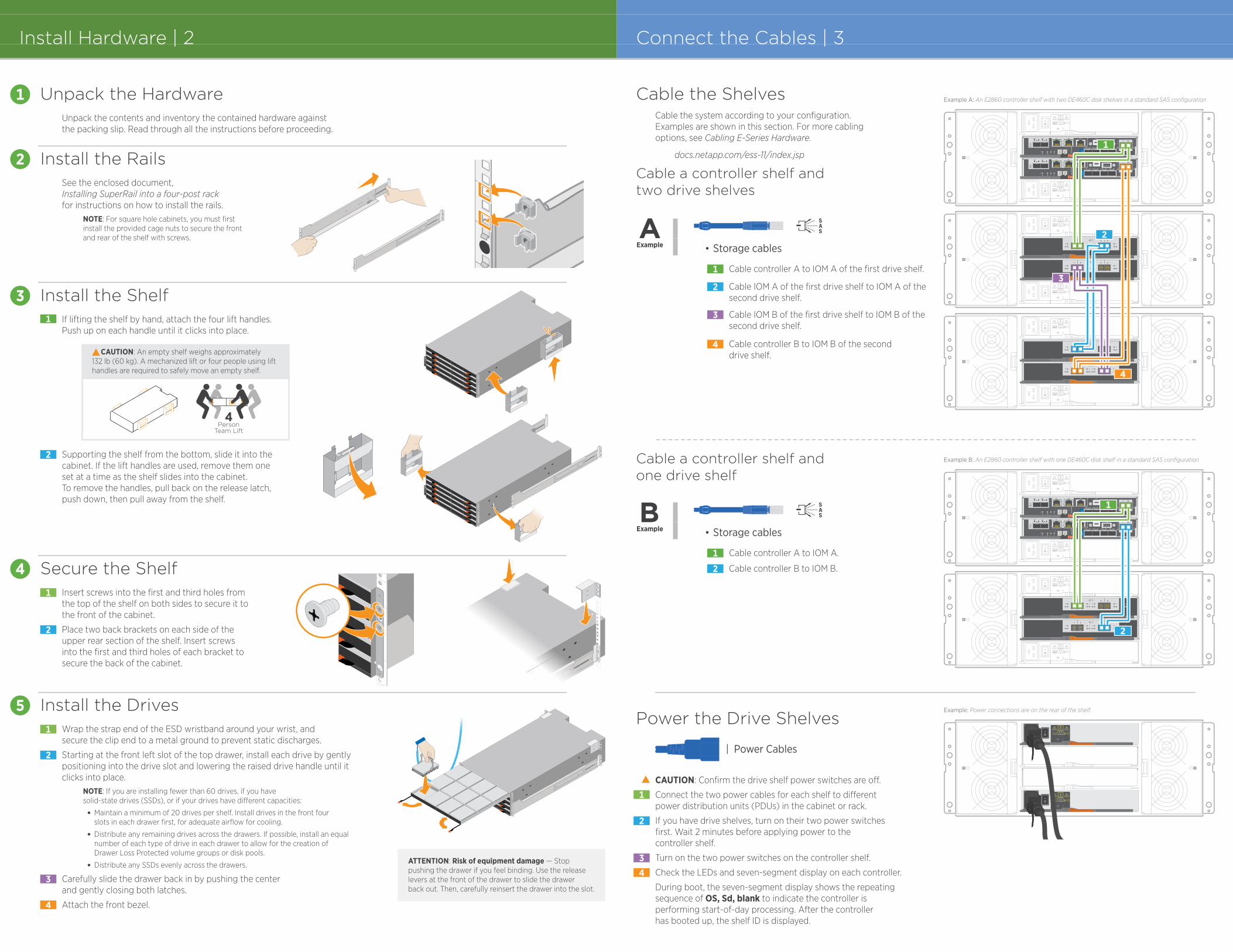
Example A: An E2860 controller shelf with two DE460C disk shelves in a standard SAS configuration
Example B: An E2860 controller shelf with one DE460C disk shelf in a standard SAS configuration
Example: Power connections are on the rear of the shelf.
Cable the ShelvesCable the system according to your configuration.Examples are shown in this section. For more cablingoptions, see Cabling E-Series Hardware.
Power the Drive Shelves
Example
Cable a controller shelf andtwo drive shelves
docs.netapp.com/ess-11/index.jsp
Storage cables
Cable a controller shelf andone drive shelf
Cable controller A to IOM A of the first drive shelf.1
Cable IOM A of the first drive shelf to IOM A of thesecond drive shelf.
2
Cable IOM B of the first drive shelf to IOM B of the second drive shelf.
3
Cable controller B to IOM B of the second drive shelf.
4
CAUTION: Confirm the drive shelf power switches are o�.
Turn on the two power switches on the controller shelf.
Check the LEDs and seven-segment display on each controller.
During boot, the seven-segment display shows the repeating sequence of OS, Sd, blank to indicate the controller is performing start-of-day processing. After the controllerhas booted up, the shelf ID is displayed.
Connect the two power cables for each shelf to di�erent power distribution units (PDUs) in the cabinet or rack.
If you have drive shelves, turn on their two power switchesfirst. Wait 2 minutes before applying power to thecontroller shelf.
1
2
34
| Power Cables
0a 0bP1 P2
EXP1 EXP20c 0d 0f0e
0a 0bP1 P2
EXP1 EXP20c 0d 0f0e
21 43
21 43
21 43
21 43
1
2
3
4
1
2
Example Storage cables
Cable controller A to IOM A.1
Cable controller B to IOM B.2
1
2
3
4
5
ATTENTION: Risk of equipment damage — Stop pushing the drawer if you feel binding. Use the releaselevers at the front of the drawer to slide the drawerback out. Then, carefully reinsert the drawer into the slot.