e pedition xp1000 - samson technologies€¦ · ratus. when a cart is used, use caution when moving...
TRANSCRIPT
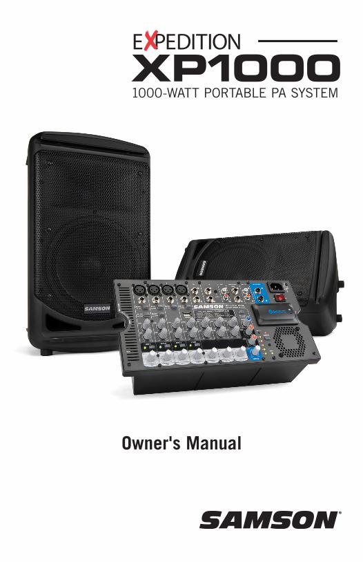
Owner's Manual
1000-WATT PORTABLE PA SYSTEMXP1000E PEDITION

Copyright 2014v1.3Samson Technologies Corp.45 Gilpin AvenueHauppauge, New York 11788-8816Phone: 1-800-3-SAMSON (1-800-372-6766)Fax: 631-784-2201 www.samsontech.com
The Bluetooth® word mark and logos are registered trademarks owned by Bluetooth SIG, Inc. and any use of such marks by Samson Technologies is under license. Other trademarks and trade names are those of their respective owners.”

XP1000 • Portable PA System
Important Safety Information
WARNING: TO REDUCE THE RISK OF ELECTRIC SHOCK, DO NOT REMOVE COVER (OR BACK) AS THERE ARE NO USER-SERVICEABLE PARTS INSIDE. REFER SERVICING TO QUALIFIED SERVICE PERSONNEL.
This lightning flash with arrowhead symbol within an equilateral triangle is intended to alert the user to the presence of non-insulated “dangerous voltage” within the product’s enclosure that may be of sufficient magni-tude to constitute a risk of electric shock.
The exclamation point within an equilateral triangle is intended to alert the user to the presence of important operating and maintenance in-structions in the literature accompanying the appliance.
AVISRISQUE DE CHOC ÉLECTRONIQUE -
NE PAS OUVRIR
If you want to dispose this product, do not mix it with general household waste. There is a separate collection system for used electronic products in accordance with legislation that requires proper treatment, recovery and recycling.
Private household in the 28 member states of the EU, in Switzerland and Norway may return their used electronic products free of charge to designated collection facilities or to a retailer (if you purchase a similar new one).
For Countries not mentioned above, please contact your local authorities for a correct method of disposal.
By doing so you will ensure that your disposed product undergoes the necessary treatment, recovery and recycling and thus prevent potential negative effects on the environment and human health.

1. Read these instructions.
2. Keep these instructions.
3. Heed all warnings.
4. Follow all instructions.
5. Do not use this apparatus near water.
6. Clean only with dry cloth.
7. Do not block any ventilation openings. Install in accordance with the manu-facturer’s instructions.
8. Do not install near any heat sources such as radiators, heat registers, stoves, or other apparatus (including amplifiers) that produce heat.
9. Do not defeat the safety purpose of the polarized or grounding type plug. A polarized plug has two blades with one wider than the other. A grounding type plug has two blades and a third grounding prong. The wide blade or the third prong are provided for your safety. If the provided plug does not fit into your outlet, consult an electri-cian for replacement of the obsolete outlet.
10. Protect the power cord from being walked on or pinched particularly at the plugs, convenience receptacles, and at the point where they exit from the apparatus.
11. Only use attachments/accessories specified by the manufacturer.
12. Use only with the cart, stand, tripod, bracket, or table specified by the manufacturer, or sold with the appa-ratus. When a cart is used, use caution when moving the cart/apparatus combination to avoid injury from tip-over.
13. Unplug the apparatus during lighten-ing storms or when unused for long periods of time.
14. Refer all servicing to qualified personnel. Service is required when the apparatus has been damaged in any way, such as power supply cord or plug is damaged, liquid has been spilled or objects have fallen into the apparatus has been exposed to rain or moisture, does not operate normally, or has been dropped.
15. This appliance shall not be exposed to dripping or splashing water and that no object filled with liquid such as vases shall be placed on the appa-ratus.
16. Caution-to prevent electrical shock, match wide blade plug wide slot fully insert.
17. Please keep a good ventilation envi-ronment around the entire unit.
18. To prevent injury, this apparatus must be securely attached to the stand in accordance with the installation instructions.
19. WARNING: The battery (battery or batteries or battery pack) shall not be exposed to excessive heat such as sunshine, fire or the like.
20. CAUTION: Danger of explosion if bat-tery is incorrectly replaced. Replace only with the same or equivalent type.
Important Safety Information
XP1000 • Portable PA System
Important Safety InformationFCC Notice
1. This device complies with Part 15 of the FCC Rules. Operation is subject to the follow-ing two conditions:
(1) This device may not cause harmful interference.
(2) This device must accept any interference received, including interference that may cause undesired operation.
2. Changes or modifications not expressly approved by the party responsible for compli-ance could void the user’s authority to operate the equipment.
FCC Statement
This equipment has been tested and found to comply with the limits for a Class B dig-ital device, pursuant to Part 15 of the FCC Rules. These limits are designed to provide reasonable protection against harmful interference in a residential installation.
This equipment generates uses and can radiate radio frequency energy and, if not installed and used in accordance with the instructions, may cause harmful interference to radio communications. However, there is no guarantee that interference will not occur in a particular installation. If this equipment does cause harmful interference to radio or television reception, which can be determined by turning the equipment off and on, the user is encouraged to try to correct the interference by one or more of the following measures:
• Reorient or relocate the receiving antenna.
• Increase the separation between the equipment and receiver.
• Connect the equipment into an outlet on a circuit different from that to which the receiver is connected.
• Consult the dealer or an experienced radio/TV technician for help.
RF Warning Statement
The device has been evaluated to meet general RF exposure requirement. The device can be used in portable exposure condition without restriction.
This device complies with RSS-310 of Industry Canada. Operation is subject to the condition that this device does not cause harmful interference.
ContentsIntroduction . . . . . . . . . . . . . . . . . . . . . . . . . . . . .7
Features . . . . . . . . . . . . . . . . . . . . . . . . . . . . . . .8
XP1000 Mixer Layout . . . . . . . . . . . . . . . . . . . . . . . .9
Pairing with a Bluetooth® device . . . . . . . . . . . . . . . . . . 12
Setting Up the XP1000. . . . . . . . . . . . . . . . . . . . . . . 13
Quick Start . . . . . . . . . . . . . . . . . . . . . . . . . . . . 15
Applying Effects . . . . . . . . . . . . . . . . . . . . . . . . . . 17
Avoiding Feedback . . . . . . . . . . . . . . . . . . . . . . . . . 17
Stage XPD1 Wireless System (Optional) . . . . . . . . . . . . . . . 18
XP1000 Connections . . . . . . . . . . . . . . . . . . . . . . . . 20
Wiring Guide . . . . . . . . . . . . . . . . . . . . . . . . . . . . 21
Specifications . . . . . . . . . . . . . . . . . . . . . . . . . . . 22
Block Diagram . . . . . . . . . . . . . . . . . . . . . . . . . . . 23
7XP1000 • Portable PA System
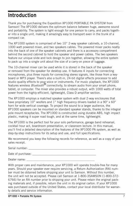
Thank you for purchasing the Expedition XP1000 PORTABLE PA SYSTEM from Samson! The XP1000 delivers the optimum balance between huge, awesome sound and portability. The system is light enough for one person to carry, and packs togeth-er into a single unit, making it amazingly easy to transport even in the trunk of a compact car.
The XP1000 system is comprised of two 10” 2-way speaker cabinets, a 10-channel, 1000 watt powered mixer, and two speakers cables. The powered mixer packs neatly into the back of one of the speaker cabinets and there is a accessory compartment behind the second cabinet to hold the speaker and power cables. The two speakers feature our unique slide and lock design to join together, allowing the entire system to pack up into a single unit about the size of a carry-on piece of luggage.
The 10-channel mixer can be used while it is stored in the back of the speaker or removed from the speaker for desktop use. It features 4 inputs for connecting microphones, plus three inputs for connecting stereo signals, like those from a key-board or MP3 player. There’s also a built-in, 24-bit digital effects processor to add studio quality effects to your voice or instruments. For music playback, the XP1000 features wireless Bluetooth® connectivity, to stream audio from your smart phone, tablet, or computer. The mixer also provides a robust output, with 1000 watts of total power from the highly-efficient, lightweight, Class D amplifier section.
The XP1000 employs a matched speaker system with dual 2-way enclosures that have proprietary 10” woofers and 1” high frequency drivers loaded in a 90° x 60° horn for wide vertical coverage. To project the sound to a larger audience, the XP1000 speakers can be mounted on standard speaker stands, thanks to the integral pole mount receptacles. The XP1000 is constructed using durable ABS, high impact plastic, making it super road tough, and at the same time, lightweight.
The XP1000 is the perfect tool for your solo performance, garage band rehearsal, cocktail hour act, boardroom presentation, or classroom lecture. In this manual, you’ll find a detailed description of the features of the XP1000 PA system, as well as step-by-step instructions for its setup and use, and full specifications.
We recommend you keep the following records for reference, as well as a copy of your sales receipt.
Serial number: ____________________________________________
Date of purchase: __________________________________________
Dealer name: _____________________________________________
With proper care and maintenance, your XP1000 will operate trouble-free for many years. Should your speaker ever require servicing, a Return Authorization (RA) num-ber must be obtained before shipping your unit to Samson. Without this number, the unit will not be accepted. Please call Samson at 1-800-3SAMSON (1-800-372-6766) for an RA number prior to shipping your unit. Please retain the original pack-ing materials and, if possible, return the unit in its original carton. If your XP1000 was purchased outside of the United States, contact your local distributor for warran-ty details and service information.
Introduction
8
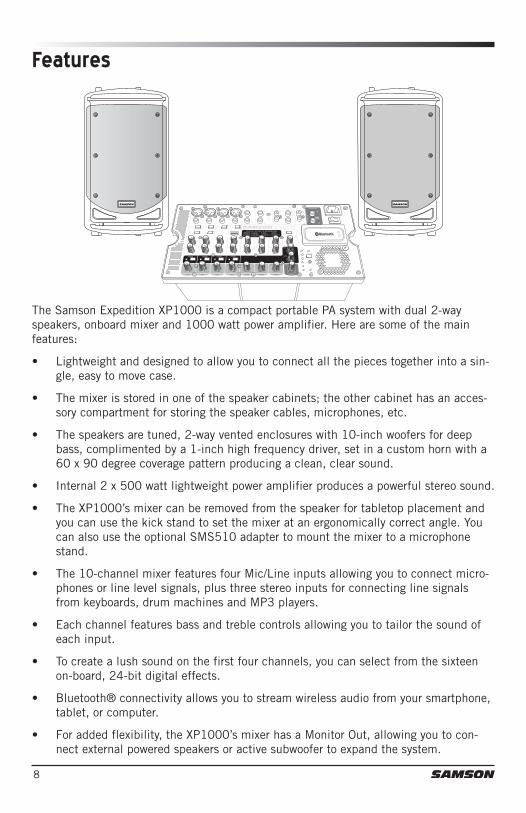
The Samson Expedition XP1000 is a compact portable PA system with dual 2-way speakers, onboard mixer and 1000 watt power amplifier. Here are some of the main features:
• Lightweight and designed to allow you to connect all the pieces together into a sin-gle, easy to move case.
• The mixer is stored in one of the speaker cabinets; the other cabinet has an acces-sory compartment for storing the speaker cables, microphones, etc.
• The speakers are tuned, 2-way vented enclosures with 10-inch woofers for deep bass, complimented by a 1-inch high frequency driver, set in a custom horn with a 60 x 90 degree coverage pattern producing a clean, clear sound.
• Internal 2 x 500 watt lightweight power amplifier produces a powerful stereo sound.
• The XP1000’s mixer can be removed from the speaker for tabletop placement and you can use the kick stand to set the mixer at an ergonomically correct angle. You can also use the optional SMS510 adapter to mount the mixer to a microphone stand.
• The 10-channel mixer features four Mic/Line inputs allowing you to connect micro-phones or line level signals, plus three stereo inputs for connecting line signals from keyboards, drum machines and MP3 players.
• Each channel features bass and treble controls allowing you to tailor the sound of each input.
• To create a lush sound on the first four channels, you can select from the sixteen on-board, 24-bit digital effects.
• Bluetooth® connectivity allows you to stream wireless audio from your smartphone, tablet, or computer.
• For added flexibility, the XP1000’s mixer has a Monitor Out, allowing you to con-nect external powered speakers or active subwoofer to expand the system.
Features
9XP1000 • Portable PA System
XP1000 Mixer Layout1
3
4
5
6
7
82 9 11 12
13
14
15
16
2220 21 23
10
19
17
18
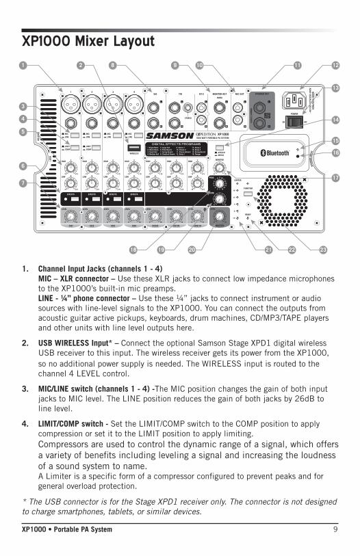
1. Channel Input Jacks (channels 1 - 4) MIC – XLR connector – Use these XLR jacks to connect low impedance microphones to the XP1000’s built-in mic preamps. LINE - ¼” phone connector – Use these ¼” jacks to connect instrument or audio sources with line-level signals to the XP1000. You can connect the outputs from acoustic guitar active pickups, keyboards, drum machines, CD/MP3/TAPE players and other units with line level outputs here.
2. USB WIRELESS Input* – Connect the optional Samson Stage XPD1 digital wireless USB receiver to this input. The wireless receiver gets its power from the XP1000, so no additional power supply is needed. The WIRELESS input is routed to the channel 4 LEVEL control.
3. MIC/LINE switch (channels 1 - 4) -The MIC position changes the gain of both input jacks to MIC level. The LINE position reduces the gain of both jacks by 26dB to line level.
4. LIMIT/COMP switch - Set the LIMIT/COMP switch to the COMP position to apply compression or set it to the LIMIT position to apply limiting. Compressors are used to control the dynamic range of a signal, which offers a variety of benefits including leveling a signal and increasing the loudness of a sound system to name. A Limiter is a specific form of a compressor configured to prevent peaks and for general overload protection.
* The USB connector is for the Stage XPD1 receiver only. The connector is not designed to charge smartphones, tablets, or similar devices.
10
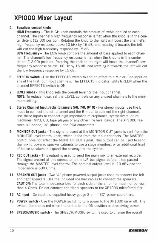
XP1000 Mixer Layout5. Equalizer control knobs
HIGH Frequency – The HIGH knob controls the amount of treble applied to each channel. The channel’s high frequency response is flat when the knob is in the cen-ter detent (12:00) position. Rotating the knob to the right will boost the channel’s high frequency response above 10 kHz by 15 dB, and rotating it towards the left will cut the high frequency response by 15 dB. LOW Frequency – The LOW knob controls the amount of bass applied to each chan-nel. The channel’s low frequency response is flat when the knob is in the center detent (12:00) position. Rotating the knob to the right will boost the channel’s low frequency response below 100 Hz by 15 dB, and rotating it towards the left will cut the low frequency response by 15 dB.
6. EFFECTS switch - Use the EFFECTS switch to add an effect to a Mic or Line input on any of the first four input channels. The EFFECTS indicator lights GREEN when the channel EFFECTS switch is ON.
7. LEVEL knobs - This knob sets the overall level for the input channel. NOTE: To reduce noise, set the LEVEL controls on any unused channels to the mini-mum setting.
8. Stereo Channel Input Jacks (channels 5/6, 7/8, 9/10) - For stereo inputs, use the L input to connect the left channel and the R input to connect the right channel. Use these inputs to connect high impedance microphones, synthesizers, drum machines, MP3, CD, tape players or any other line level device. The XP1000 fea-tures ¼” phone, ¹/8” phone, and RCA connectors.
9. MONITOR OUT jacks - The signal present at the MONITOR OUT jacks is sent from the MONITOR level control knob, which is fed from the input channels. The MASTER control does not affect the MONITOR OUT signal. This output can be used to send the mix to powered speaker cabinets to use a stage monitors, or as additional front of house speakers to expand the coverage of the system.
10. REC OUT jacks - This output is used to send the main mix to an external recorder. The signal present at this connector is the L/R bus signal before it has passed through the MASTER level control. The nominal output level is -10 dBV and the impedance is 600 Ohms.
11. SPEAKER OUT jacks - Two ¼” phone powered output jacks used to connect the left and right speakers. Use the included speaker cables to connect the speakers. CAUTION: The total impedance load for each side of the amplifier must not be less than 4 Ohms. Do not connect additional speakers to the XP1000 mixer/amplifier.
12. AC Input – Connect the supplied heavy-gauge 3-pin “IEC” power cable here.
13. POWER switch - Use the POWER switch to turn power to the XP1000 on or off. The switch illuminates red when the unit is in the ON position and receiving power.
14. SPEECH/MUSIC switch - The SPEECH/MUSIC switch is used to change the overall
11XP1000 • Portable PA System
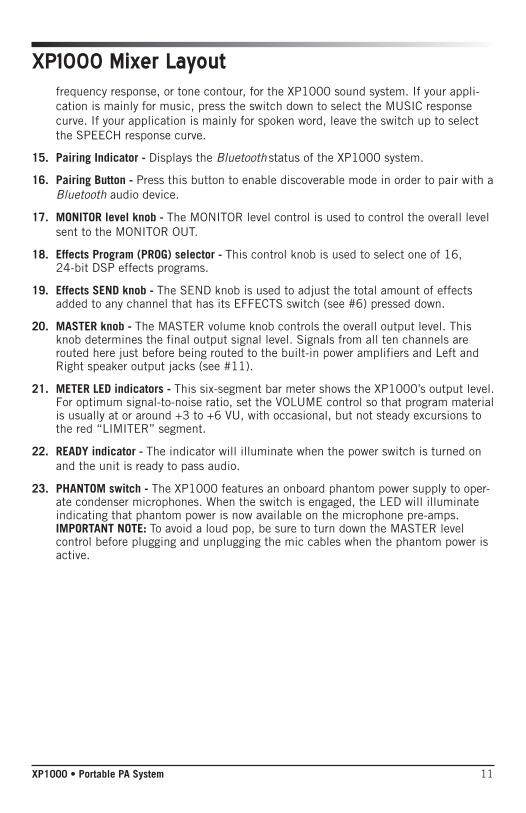
XP1000 Mixer Layoutfrequency response, or tone contour, for the XP1000 sound system. If your appli-cation is mainly for music, press the switch down to select the MUSIC response curve. If your application is mainly for spoken word, leave the switch up to select the SPEECH response curve.
15. Pairing Indicator - Displays the Bluetooth status of the XP1000 system.
16. Pairing Button - Press this button to enable discoverable mode in order to pair with a Bluetooth audio device.
17. MONITOR level knob - The MONITOR level control is used to control the overall level sent to the MONITOR OUT.
18. Effects Program (PROG) selector - This control knob is used to select one of 16, 24-bit DSP effects programs.
19. Effects SEND knob - The SEND knob is used to adjust the total amount of effects added to any channel that has its EFFECTS switch (see #6) pressed down.
20. MASTER knob - The MASTER volume knob controls the overall output level. This knob determines the final output signal level. Signals from all ten channels are routed here just before being routed to the built-in power amplifiers and Left and Right speaker output jacks (see #11).
21. METER LED indicators - This six-segment bar meter shows the XP1000’s output level. For optimum signal-to-noise ratio, set the VOLUME control so that program material is usually at or around +3 to +6 VU, with occasional, but not steady excursions to the red “LIMITER” segment.
22. READY indicator - The indicator will illuminate when the power switch is turned on and the unit is ready to pass audio.
23. PHANTOM switch - The XP1000 features an onboard phantom power supply to oper-ate condenser microphones. When the switch is engaged, the LED will illuminate indicating that phantom power is now available on the microphone pre-amps. IMPORTANT NOTE: To avoid a loud pop, be sure to turn down the MASTER level control before plugging and unplugging the mic cables when the phantom power is active.

12
Bluetooth® is a wireless communication technology that allows for connectivity between a wide range of devices. The XP1000 uses Bluetooth to stream high quality audio from your Bluetooth enabled device without the need for connecting any cables. In order for your device to work with the XP1000 it must first be paired.
1. Turn all channel LEVEL controls down counterclockwise to 0.
2. With the XP1000 and your Bluetooth device powered on; press the PAIR button on the top panel of the XP1000 mixer to make the speaker discoverable. The Blue-tooth indicator will slowly flash blue.
3. In the settings of your Bluetooth device, set it to “discover” available devices.
4. From the Bluetooth device list, select the "Samson XP1000" device.
5. If your device asks for a passkey, enter digits 0000 (four zeros) and press OK. Some devices may also ask you to accept the connection.
6. As the XP1000 is connecting to your device, the Bluetooth indicator will quickly flash blue.
7. The XP1000 speaker indicates that pairing is complete when the indicator turns steady blue. You can now stream audio from your device to the XP1000 speakers.
8. With the volume control on your Bluetooth device turned up, play some music, and slowly raise the XP1000 BLUETOOTH channel 9/10 LEVEL control until you have reached the desired level.
Pairing with a Bluetooth® device
13XP1000 • Portable PA System
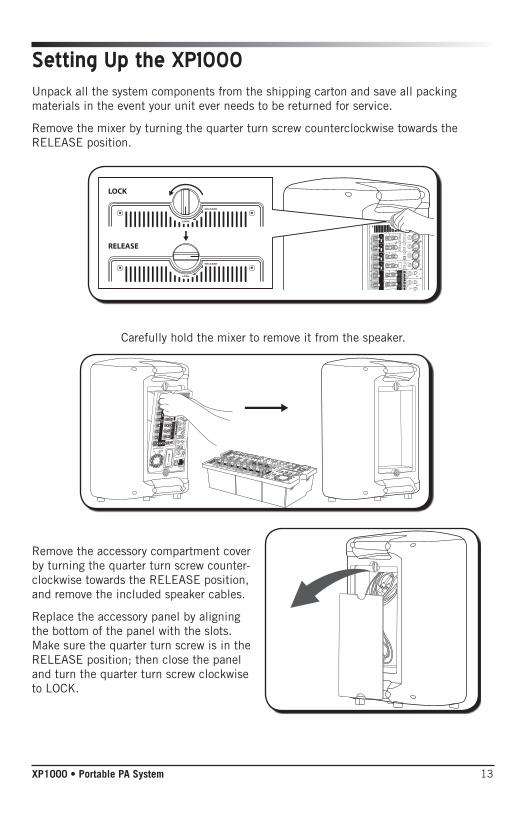
Setting Up the XP1000Unpack all the system components from the shipping carton and save all packing materials in the event your unit ever needs to be returned for service.
Remove the mixer by turning the quarter turn screw counterclockwise towards the RELEASE position.
LOCK
RELEASE
Carefully hold the mixer to remove it from the speaker.
Remove the accessory compartment cover by turning the quarter turn screw counter-clockwise towards the RELEASE position, and remove the included speaker cables.
Replace the accessory panel by aligning the bottom of the panel with the slots. Make sure the quarter turn screw is in the RELEASE position; then close the panel and turn the quarter turn screw clockwise to LOCK.
14
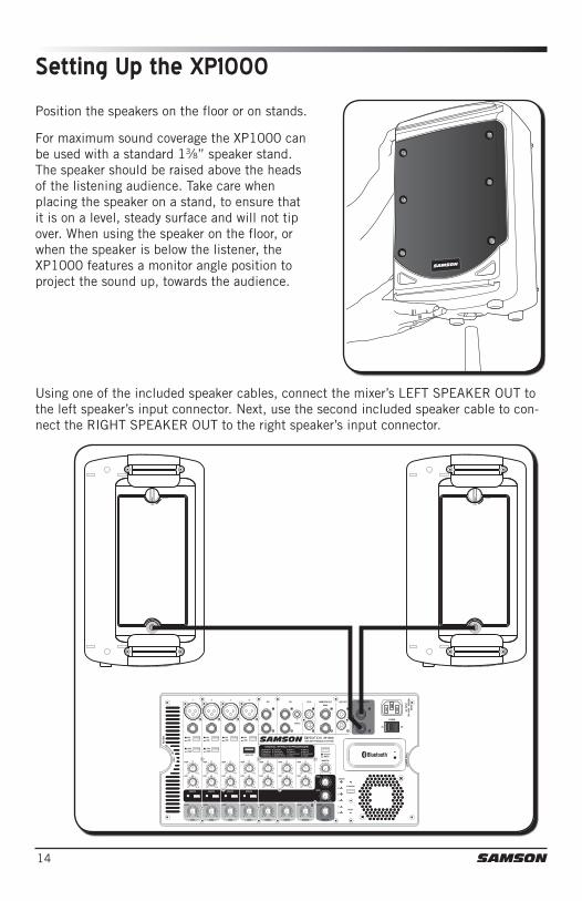
Position the speakers on the floor or on stands.
Setting Up the XP1000
Using one of the included speaker cables, connect the mixer’s LEFT SPEAKER OUT to the left speaker’s input connector. Next, use the second included speaker cable to con-nect the RIGHT SPEAKER OUT to the right speaker’s input connector.
For maximum sound coverage the XP1000 can be used with a standard 13⁄8” speaker stand. The speaker should be raised above the heads of the listening audience. Take care when placing the speaker on a stand, to ensure that it is on a level, steady surface and will not tip over. When using the speaker on the floor, or when the speaker is below the listener, the XP1000 features a monitor angle position to project the sound up, towards the audience.

15XP1000 • Portable PA System
Quick Start1. Be sure that the XP1000’s POWER switch is set to the OFF position.
2. If the speakers are not connected, connect the speaker wires as described in the previous section.
3. Turn each of the channel LEVEL and MASTER volume controls fully counterclock-wise, to the “0” position.
4. Next, connect one side of the included power cable to the XP1000 mixer’s power inlet and the other to a grounded AC power outlet.
5. Connect your microphones using standard XLR cables, instruments using ¼” phone cables, and MP3 player using ¹/8” cable, into the appropriate jacks on the mixer.
SIGNAL
SIGNAL
SIGN
ALSIGN
AL
SIGN
AL
SIGN
AL
Electric AcousticGuitar
KeyboardDynamic Microphone
6. Switch on all equipment connected to the XP1000, then switch the XP1000’s POWER switch to the ON position.
7. Turn the MASTER level control up halfway, to the “5” position.
8. Start talking or playing into channel 1 while slowly adjusting the LEVEL control until you have reached the desired level. Do the same for each channel you are using.

16
XP1000 Quick Start9. If you notice that the LIMITER indicator is lighting constantly, turn the MASTER
volume down so that the indicator only lights occasionally during loud hits.
10. To add depth to the mix or smooth out the vocals, you can apply effects such as reverb to channels 1–4. To do this, press the EFFECTS button on the channel(s) to which you would like to add the effect.
11. Slowly turn up the effects SEND knob until the desired sound is reached.
12. To alter the tonal characteristic of the signal, you can adjust the LOW (bass) and HIGH (treble) controls. If you find the audio too muddy, you may want to reduce the LOW control. If you find that the audio sounds dull, you can increase the HIGH control. There is no right or wrong way to EQ a sound. You should listen to how the mix sounds in the room and fine-tune to your liking.
17XP1000 • Portable PA System
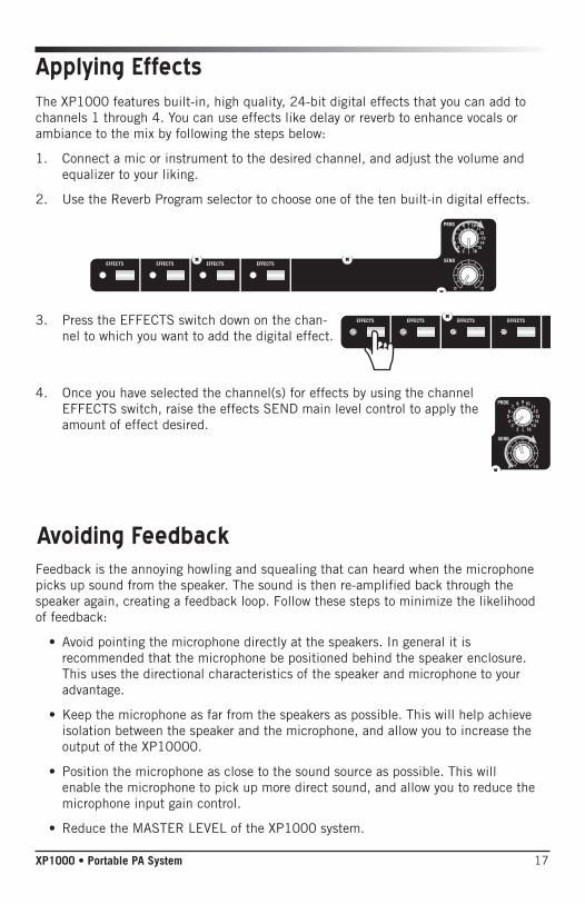
Applying EffectsThe XP1000 features built-in, high quality, 24-bit digital effects that you can add to channels 1 through 4. You can use effects like delay or reverb to enhance vocals or ambiance to the mix by following the steps below:
1. Connect a mic or instrument to the desired channel, and adjust the volume and equalizer to your liking.
2. Use the Reverb Program selector to choose one of the ten built-in digital effects.
3. Press the EFFECTS switch down on the chan-nel to which you want to add the digital effect.
4. Once you have selected the channel(s) for effects by using the channel EFFECTS switch, raise the effects SEND main level control to apply the amount of effect desired.
Feedback is the annoying howling and squealing that can heard when the microphone picks up sound from the speaker. The sound is then re-amplified back through the speaker again, creating a feedback loop. Follow these steps to minimize the likelihood of feedback:
• Avoid pointing the microphone directly at the speakers. In general it is recommended that the microphone be positioned behind the speaker enclosure. This uses the directional characteristics of the speaker and microphone to your advantage.
• Keep the microphone as far from the speakers as possible. This will help achieve isolation between the speaker and the microphone, and allow you to increase the output of the XP10000.
• Position the microphone as close to the sound source as possible. This will enable the microphone to pick up more direct sound, and allow you to reduce the microphone input gain control.
• Reduce the MASTER LEVEL of the XP1000 system.
Avoiding Feedback
18
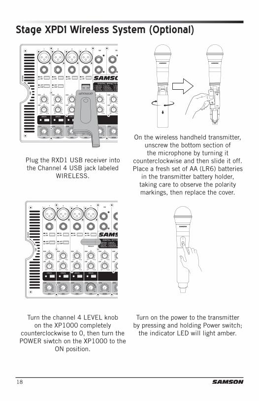
Plug the RXD1 USB receiver into the Channel 4 USB jack labeled
WIRELESS.
On the wireless handheld transmitter, unscrew the bottom section of the microphone by turning it
counterclockwise and then slide it off. Place a fresh set of AA (LR6) batteries
in the transmitter battery holder, taking care to observe the polarity markings, then replace the cover.
Turn the channel 4 LEVEL knob on the XP1000 completely
counterclockwise to 0, then turn the POWER siwtch on the XP1000 to the
ON position.
Turn on the power to the transmitter by pressing and holding Power switch;
the indicator LED will light amber.
Stage XPD1 Wireless System (Optional)

19XP1000 • Portable PA System
If the handheld transmitter and receiver have not been previously
paired, press and hold the button on the RXD1 receiver for >5 seconds,
until it begins to flash.
Press and hold the Power button on the handheld transmitter >5 seconds.
This will put both components into pairing modes. Once the receiver and transmitter communicate and sync,
the LEDs on both units will light steady and will be ready for operation.
Raise the MASTER LEVEL control and speak or sing into the mic at a normal
performance level while raising the Channel 4 LEVEL control until the
desired level is reached.
If you hear distortion check the LIMITER LED. If it is lit red, turn
down the channel 4 LEVEL on the XP1000 until it lights only
occasionally during loud sounds. If you still hear distortion, unscrew the
microphone body and use the supplied plastic screwdriver to turn the Gain
control in the HXD1 transmitter slowly counterclockwise until the distortion
disappears. Conversely, if you hear a weak, noisy
signal at the desired volume level (and with the WIRELESS control of the XP1000 turned fully clockwise), use the supplied plastic screwdriver to turn the Gain control in the HXD1 transmitter slowly clockwise until the signal reaches an acceptable level.
Stage XPD1 Wireless System (Optional)
20
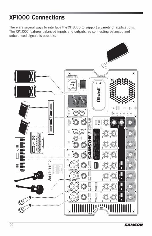
There are several ways to interface the XP1000 to support a variety of applications. The XP1000 features balanced inputs and outputs, so connecting balanced and unbalanced signals is possible.
XP1000 Connections
Bas
s P
ream
p
21XP1000 • Portable PA System
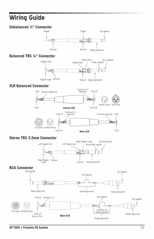
Wiring GuideUnbalanced ¼” Connector
Balanced TRS ¼” Connector
XLR Balanced Connector
Signal
Ground Ground Sleeve (ground)
Signal Tip (signal)
+Signal (tip) +Signal (tip)-Signal (tip)
Ring (-signal)Tip (+signal)
Ground-Signal (ring) Ground Sleeve (ground)
-Cold (3)
+Hot (2)Common (1)
(ground)
-Cold
+Hot Common (ground)
End ViewSolder Points
Female XLR
Male XLR -Cold-Cold (3)
+HotCommon (ground)+Hot (2)Common (1)
(ground)
End View Solder Points
Stereo TRS 3.5mm Connector
RCA Connector
Sleeve (ground)GroundGround
Tip (left signal)Ring (right signal)
Right Signal (ring)
Right Signal (ring)
Left Signal (tip)Left Signal (tip)
Tip (signal)
Sleeve (ground)
Tip (signal)
Sleeve (ground)
Tip (signal)
Sleeve (ground)
Tip (signal)
Sleeve (ground)
23
1
Male XLR
Hot (2)
Cold (3)Tied to Pin 1
Common (1)
End View Solder Points
1 23
Tip (signal)
Sleeve (ground)
Cold (Pin 3)Sleeve (ground)
Tip (signal)
Sleeve (ground)
Tip (signal)
Sleeve (ground)
Tip (signal)
Sleeve (ground)
Tip (signal)
Sleeve (ground)
23
1
Male XLR
Hot (2)
Cold (3)Tied to Pin 1
Common (1)
End View Solder Points
1 23
Tip (signal)
Sleeve (ground)
Cold (Pin 3)Sleeve (ground)
22
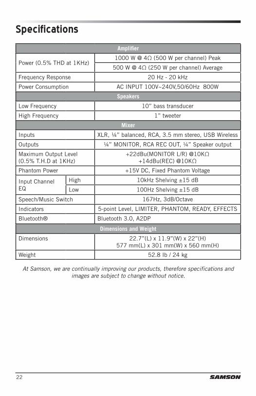
Specifications
Amplifier
Power (0.5% THD at 1KHz)1000 W @ 4Ω (500 W per channel) Peak
500 W @ 4Ω (250 W per channel) Average
Frequency Response 20 Hz - 20 kHz
Power Consumption AC INPUT 100V~240V,50/60Hz 800W
Speakers
Low Frequency 10” bass transducer
High Frequency 1” tweeter
Mixer
Inputs XLR, ¼” balanced, RCA, 3.5 mm stereo, USB Wireless
Outputs ¼” MONITOR, RCA REC OUT, ¼” Speaker output
Maximum Output Level (0.5% T.H.D at 1KHz)
+22dBu(MONITOR L/R) @10KΩ +14dBu(REC) @10KΩ
Phantom Power +15V DC, Fixed Phantom Voltage
Input Channel EQ
High 10kHz Shelving ±15 dB
Low 100Hz Shelving ±15 dB
Speech/Music Switch 167Hz, 3dB/Octave
Indicators 5-point Level, LIMITER, PHANTOM, READY, EFFECTS
Bluetooth® Bluetooth 3.0, A2DP
Dimensions and Weight
Dimensions 22.7’’(L) x 11.9’’(W) x 22’’(H)577 mm(L) x 301 mm(W) x 560 mm(H)
Weight 52.8 Ib / 24 kg
At Samson, we are continually improving our products, therefore specifications and images are subject to change without notice.
23XP1000 • Portable PA System
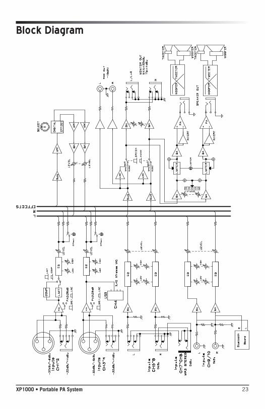
Block Diagram

Samson Technologies Corp. 45 Gilpin Avenue
Hauppauge, New York 11788-8816 Phone: 1-800-3-SAMSON (1-800-372-6766)
Fax: 631-784-2201 www.samsontech.com