e manual bms graf pro - bartecautomation.bartec.de/dataroot/bmsgraf/v5/e_user... · user manual for...
TRANSCRIPT

SoftwareBMS Graf proUser Manual

E_Handbuch_BMSGrafPro_V50xx.doc • User manual for BMS Graf pro • Revision 1 / Status: March 8th, 2004 • Technical data subject to change
User manual for BMS Graf pro Version 5.0.x.x
Editor and Copyright: BARTEC GmbH Max-Eyth-Strasse 16 97980 Bad Mergentheim Germany Telephone: +49 7931 597-0 (Head office) Telefax: +49 7931 597-183 All rights reserved. Reproductions and extracts from this document are prohibited without the written permission of the editor. Much care has been taken in producing this manual. However, BARTEC GmbH does not assume responsibility for errors in this manual nor any resulting consequences. Likewise any liability is rejected, should the product be used incorrectly. We have taken care to include correctly and completely all the necessary information for the successful installation, configuration and operation of the display is in this manual. Should you require further information or find errors in this manual, please contact us. IBM is a registered trademark of the IBM Corporation SIMATIC S5 is a registered trademark of the Siemens AG SIMATIC PG is a registered trademark of the Siemens AG MS DOS is a registered trademark of the MICROSOFT Corporation WINDOWS is a registered trademark of the MICROSOFT Corporation
User manual for BMS Graf pro Version V5.0.x.x Page 2
E_Handbuch_BMSGrafPro_V50xx.doc • User manual for BMS Graf pro • Revision 1 / Status: March 8th, 2004 • Technical data subject to change
Table of contents
1 Installation of BMS Graf pro........................................................................................................................ 5 1.1 Requirements................................................................................................................................................5 1.1.1 Minimum hardware requirements .................................................................................................................5 1.1.2 Recommended..............................................................................................................................................5 1.1.3 Software requirements..................................................................................................................................5 1.1.4 Copyright ....................................................................................................................................................5 1.1.5 Completion of the registration card ...............................................................................................................5 1.2 Installation of BMS Graf pro..........................................................................................................................6
2 Description of software ............................................................................................................................... 7 2.1 Project modules / definitions .........................................................................................................................7
3 Using BMS Graf pro ..................................................................................................................................... 8 3.1 Program selection .........................................................................................................................................8 3.2 The start screen ............................................................................................................................................8 3.3 Menus and symbol bars................................................................................................................................9 3.3.1 For closed projects........................................................................................................................................9 3.3.2 For opened projects ....................................................................................................................................10 3.4 Drafting of a project.....................................................................................................................................11 3.4.1 The project overview...................................................................................................................................11 3.4.2 The project information field........................................................................................................................11 3.4.3 Terminal selection.......................................................................................................................................12 3.4.3.1 Display terminals.........................................................................................................................................12 3.4.4 Selection of coupling interface ....................................................................................................................13 3.4.4.1 Available interpreters ..................................................................................................................................13 3.4.4.2 The transfer block .......................................................................................................................................14
4 Alarm messages......................................................................................................................................... 19 4.1 Alarm overview............................................................................................................................................19 4.1.1 The alarm overview menu...........................................................................................................................19 4.2 Modification of alarms .................................................................................................................................20
5 Variables ..................................................................................................................................................... 22 5.1 Overview .....................................................................................................................................................22 5.1.1 The Variables-overview menu ....................................................................................................................22 5.2 Modification of variables .............................................................................................................................23
6 Texts ............................................................................................................................................................ 25 6.1 Text-list overview ........................................................................................................................................25 6.1.1 The text-list overview menu ........................................................................................................................25 6.2 Editing of text lists .......................................................................................................................................26 6.2.1 Bit–oriented list text.....................................................................................................................................27 6.2.2 Value-oriented list text ................................................................................................................................27
User manual for BMS Graf pro Version V5.0.x.x Page 3
E_Handbuch_BMSGrafPro_V50xx.doc • User manual for BMS Graf pro • Revision 1 / Status: March 8th, 2004 • Technical data subject to change
Table of contents
7 Drafting and editing images...................................................................................................................... 28 7.1 Images overview .........................................................................................................................................28 7.1.1 The images overview menu ........................................................................................................................28 7.2 The image editor .........................................................................................................................................29 7.2.1 Overview ..................................................................................................................................................29 7.2.2 Tool bar ..................................................................................................................................................29 7.2.2.1 The selection arrow.....................................................................................................................................29 7.2.2.2 The symbol functions ..................................................................................................................................30 7.2.2.3 Editing texts.................................................................................................................................................30 7.2.2.4 Entry boxes .................................................................................................................................................31 7.2.2.5 Output boxes...............................................................................................................................................32 7.2.2.6 Line writer ..................................................................................................................................................33 7.2.2.7 Bar graphs ..................................................................................................................................................34 7.2.2.8 Barcode entry boxes ...................................................................................................................................35 7.2.2.9 Scaleable entry boxes.................................................................................................................................36 7.2.2.10 Scalable output boxes.................................................................................................................................37 7.2.2.11 Date output box...........................................................................................................................................38 7.2.2.12 Time output box ..........................................................................................................................................38 7.2.2.13 Text-lists output...........................................................................................................................................39 7.2.2.14 Text-lists entry.............................................................................................................................................40 7.2.2.15 Embed bit map............................................................................................................................................41 7.2.3 Depiction tools.............................................................................................................................................42 7.2.3.1 Zoom functions............................................................................................................................................42 7.2.3.2 Pan function ................................................................................................................................................42 7.2.3.3 Settings/grids ..............................................................................................................................................42 7.2.3.4 Grey-scale view...........................................................................................................................................42 7.2.3.5 Settings/copying/mirror-imaging/rotating ....................................................................................................43 7.2.3.6 Scale view ..................................................................................................................................................43 7.2.3.7 Object tree ..................................................................................................................................................43 7.2.4 Editing tools.................................................................................................................................................44 7.2.4.1 Grouping/separating ...................................................................................................................................44 7.2.4.2 Foreground/background..............................................................................................................................44 7.2.4.3 Copying ..................................................................................................................................................44 7.2.4.4 Mirror-imaging .............................................................................................................................................44 7.2.4.5 Rotate ..................................................................................................................................................44 7.2.4.6 Delete ..................................................................................................................................................45 7.2.4.7 Assign filling color and background color....................................................................................................45 7.2.4.8 Assign pencil colour/margin colour .............................................................................................................45 7.2.4.9 Assign pencil pattern...................................................................................................................................46 7.2.4.10 Assign pencil width .....................................................................................................................................46 7.2.4.11 Assign filling pattern....................................................................................................................................46 7.2.5 Image settings.............................................................................................................................................47 7.2.5.1 Assign basic image data .............................................................................................................................47 7.2.5.2 Key assignments.........................................................................................................................................48 7.2.5.3 Symbol library .............................................................................................................................................50 7.3 Object tree...................................................................................................................................................51 7.4 Assignment of actions to objects ................................................................................................................52

User manual for BMS Graf pro Version V5.0.x.x Page 4
E_Handbuch_BMSGrafPro_V50xx.doc • User manual for BMS Graf pro • Revision 1 / Status: March 8th, 2004 • Technical data subject to change
Table of contents
8 Transfer project to the display terminal................................................................................................... 53
9 Print project ................................................................................................................................................ 54 9.1 Printer settings ............................................................................................................................................54 9.2 Print preview ...............................................................................................................................................55 9.3 Print scope ..................................................................................................................................................55
Appendix A .................................................................................................................................................... 57 Appendix B .................................................................................................................................................. 115

User manual for BMS Graf pro Version V5.0.x.x Page 5
E_Handbuch_BMSGrafPro_V50xx.doc • User manual for BMS Graf pro • Revision 1 / Status: March 8th, 2004 • Technical data subject to change
1 Installation of BMS Graf pro
1.1 Requirements
1.1.1 Minimum hardware requirements Pentium II processor, 233 MHz or higher 128 MB memory 40 MB free hard-disk space CD-ROM for installation Mouse Graphics resolution 1024 x 768 pixels, 16-bit colour depth 1 serial interface (COM1 or COM2) for transfer of project data to the BAT terminal Printer (local or network)
1.1.2 Recommended 256 MB memory 60 MB free hard-disk space Graphics resolution 1280 x 1024 pixels, 32-bit colour depth
1.1.3 Software requirements Operating system: Microsoft Windows 95, 98, ME, NT4, NT5, 2000 or XP
1.1.4 Copyright
IMPORTANT
This software is protected by copyright. By opening the package, you automatically accept the conditions of the license agreement. You may make only one single copy of the original data-bearers for safety reasons and for archiving purposes.
1.1.5 Completion of the registration card
Not planned at present.

User manual for BMS Graf pro Version V5.0.x.x Page 6
E_Handbuch_BMSGrafPro_V50xx.doc • User manual for BMS Graf pro • Revision 1 / Status: March 8th, 2004 • Technical data subject to change
1.2 Installation of BMS Graf pro A sub-directory into which all BMS Graf pro files will be written is created during the installation process.
(1) Before installing, make a back-up copy of any already existing version of BMS Graf pro.
(2) Check that one of the following operating systems is installed:
Microsoft Windows 95
Microsoft Windows 98
Microsoft Windows ME
Microsoft Windows NT4
Microsoft Windows NT5
Microsoft Windows 2000
Microsoft Windows XP
(3) Ensure that you possess the necessary rights to install the software.
(4) Insert the BMS Graf pro CD in your CD-ROM drive.
(5) Open the main directory of your CD-ROM drive using Explorer.
(6) Start installation by selecting the "SETUP.EXE" file.
(7) Follow the instructions in the installation software.
(8) After installation, remove the BMS Graf pro CD from the drive and keep it in a safe place. The CD is not needed during operation of the software.
(9) BMS Graf pro can be started via the start menu, "Programs"
Please see the Windows documentation for more details on Windows.
User manual for BMS Graf pro Version V5.0.x.x Page 7
E_Handbuch_BMSGrafPro_V50xx.doc • User manual for BMS Graf pro • Revision 1 / Status: March 8th, 2004 • Technical data subject to change
2 Description of software
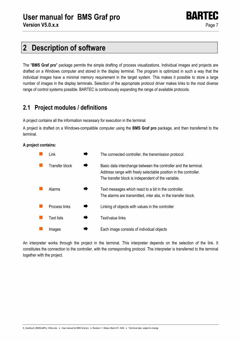
The "BMS Graf pro" package permits the simple drafting of process visualizations. Individual images and projects are drafted on a Windows computer and stored in the display terminal. The program is optimized in such a way that the individual images have a minimal memory requirement in the target system. This makes it possible to store a large number of images in the display terminals. Selection of the appropriate protocol driver makes links to the most diverse range of control systems possible. BARTEC is continuously expanding the range of available protocols.
2.1 Project modules / definitions
A project contains all the information necessary for execution in the terminal. A project is drafted on a Windows-compatible computer using the BMS Graf pro package, and then transferred to the terminal.
A project contains:
Link The connected controller, the transmission protocol.
Transfer block Basic data interchange between the controller and the terminal. Address range with freely selectable position in the controller. The transfer block is independent of the variable.
Alarms Text messages which react to a bit in the controller. The alarms are transmitted, inter alia, in the transfer block.
Process links Linking of objects with values in the controller
Text lists Text/value links
Images Each image consists of individual objects
An interpreter works through the project in the terminal. This interpreter depends on the selection of the link. It constitutes the connection to the controller, with the corresponding protocol. The interpreter is transferred to the terminal together with the project.
User manual for BMS Graf pro Version V5.0.x.x Page 8
E_Handbuch_BMSGrafPro_V50xx.doc • User manual for BMS Graf pro • Revision 1 / Status: March 8th, 2004 • Technical data subject to change
3 Using BMS Graf pro
3.1 Program selection
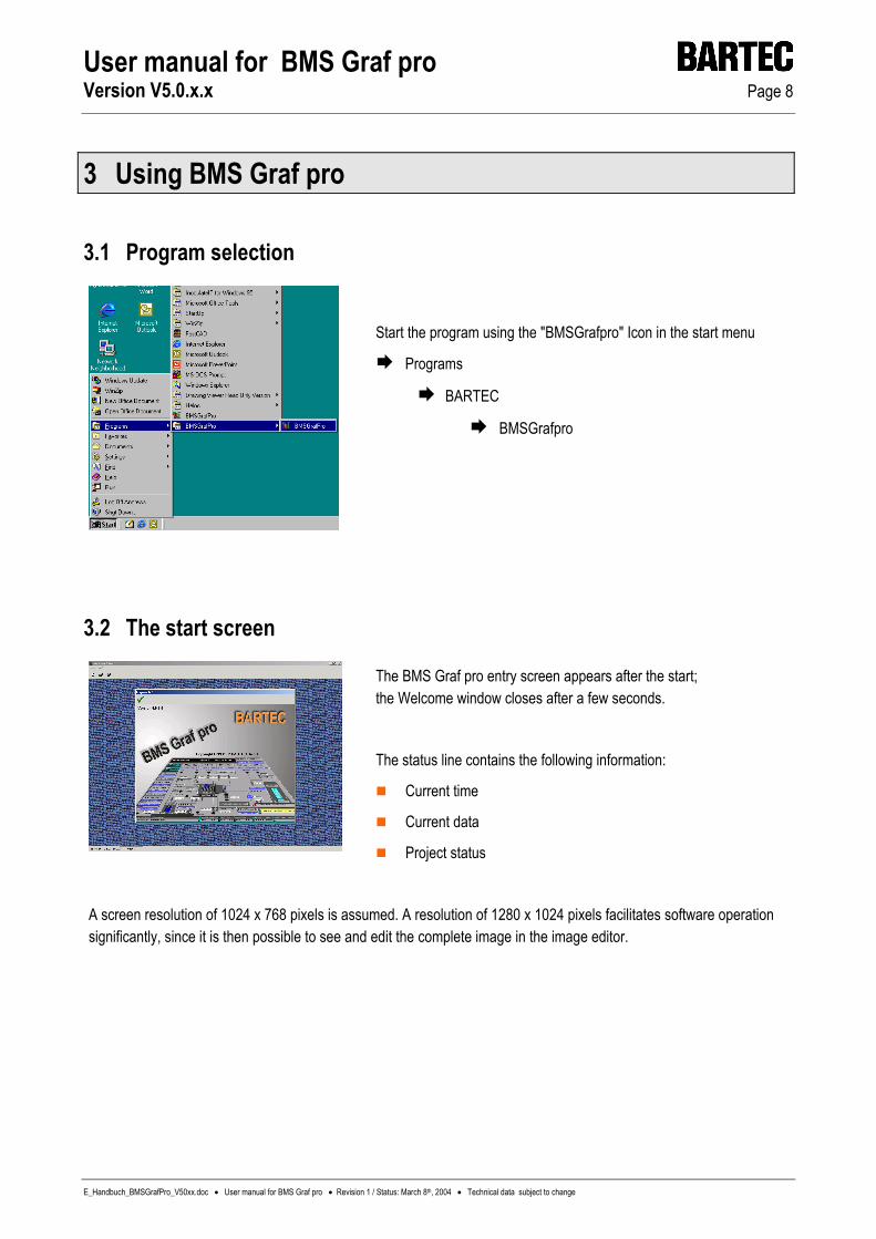
Start the program using the "BMSGrafpro" Icon in the start menu
Programs
BARTEC
BMSGrafpro
3.2 The start screen
The BMS Graf pro entry screen appears after the start; the Welcome window closes after a few seconds.
The status line contains the following information:
Current time
Current data
Project status
A screen resolution of 1024 x 768 pixels is assumed. A resolution of 1280 x 1024 pixels facilitates software operation significantly, since it is then possible to see and edit the complete image in the image editor.
User manual for BMS Graf pro Version V5.0.x.x Page 9
E_Handbuch_BMSGrafPro_V50xx.doc • User manual for BMS Graf pro • Revision 1 / Status: March 8th, 2004 • Technical data subject to change
3.3 Menus and symbol bars
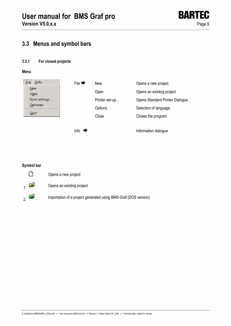
3.3.1 For closed projects
Menu
File New Opens a new project
Open Opens an existing project
Printer set-up... Opens Standard Printer Dialogue
Options Selection of language
Close Closes the program
Info Information dialogue
Symbol bar
Opens a new project
1. Opens an existing project
2. Importation of a project generated using BMS-Graf (DOS version)
User manual for BMS Graf pro Version V5.0.x.x Page 10
E_Handbuch_BMSGrafPro_V50xx.doc • User manual for BMS Graf pro • Revision 1 / Status: March 8th, 2004 • Technical data subject to change
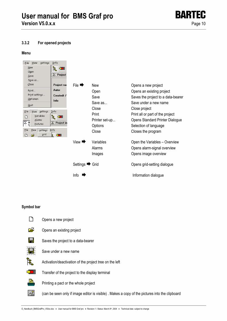
3.3.2 For opened projects
Menu
File New Opens a new project Open Opens an existing project Save Saves the project to a data-bearer Save as... Save under a new name Close Close project Print Print all or part of the project Printer set-up... Opens Standard Printer Dialogue Options Selection of language Close Closes the program View Variables Open the Variables – Overview Alarms Opens alarm-signal overview Images Opens image overview Settings Grid Opens grid-setting dialogue Info Information dialogue
Symbol bar
Opens a new project
Opens an existing project
Saves the project to a data-bearer
Save under a new name
Activation/deactivation of the project tree on the left
Transfer of the project to the display terminal
Printing a pact or the whole project
(can be seen only if image editor is visible) . Makes a copy of the pictures into the clipboard

User manual for BMS Graf pro Version V5.0.x.x Page 11
E_Handbuch_BMSGrafPro_V50xx.doc • User manual for BMS Graf pro • Revision 1 / Status: March 8th, 2004 • Technical data subject to change
3.4 Drafting of a project
3.4.1 The project overview
Information Data and information on the project Designation of the current project Depiction of the selected controller and coupling
interface Depiction of the terminal selected Information on number of images and number of
alarms for the project Terminal Selection of the display terminal used
Coupling Selection of the controller and the protocol used interface Statement of the transfer block addresses in the
controller
Variables Assignment of variable-names to addresses in the controller
Images Drafting or editing of individual images Alarms Input of alarm texts and statement of their reaction Print Print-out of alarms, assignments and information
Transfer Download of the entire project to the terminal connected
Note: Default values are used (BAT 2 as terminal and SELFRUN as coupling interface) for the drafting of a new project,
these can be changed at any time
Detailed information on the individual items is available on the following pages
3.4.2 The project information field
Information: General information on the project. This information can be changed at any time.

User manual for BMS Graf pro Version V5.0.x.x Page 12
E_Handbuch_BMSGrafPro_V50xx.doc • User manual for BMS Graf pro • Revision 1 / Status: March 8th, 2004 • Technical data subject to change
3.4.3 Terminal selection
Terminal: A terminal can be selected using the cursor keys and/or the mouse
Confirm settings
Reject settings
3.4.3.1 Display terminals The display terminals are available in five housing variants. The BAT 2 (monochrome), the follow-up model BAT 300, the BAT VGA (color) and the follow-up model BAT VGA Pro (color TFT) and the new BAT 800. Characteristic features The display terminals are notable, in particular, for the following performance features:
BAT 2 BAT VGA BAT VGA pro BAT 300 BAT 800 Display resolution ¼ VGA
320 x 240 pixels VGA
640 x 480 pixels VGA
640 x 480 pixels ¼ VGA
320 x 240 pixels SVGA
800 x 600 pixels
Display mode monochrome ( 16 grey-levels )
Colour ( 16 colors )
Colour 262144 colors
Colour 262144 colors
Colour 262144 colors
Display size 5.7 “ approx. 115 x 86 mm
10.4 “ approx. 212 x 159 mm
10.4 “ approx. 212 x 159 mm
5.5 “ approx. 111,4 x 83,5 mm
12 “ approx. 247,5 x 186 mm
Keyboard numeric pad 10 function keys (can be
labeled)
numeric pad 12 function keys (can be labeled)
numeric pad 12 functions key (can be labeled)
numeric pad 10 functions key (can be labeled) 6 special keys
numeric pad 16 functions key (can be labeled) 12 special keys
Systems keys Com1: TTY or RS232 or RS422/RS485 Com2: RS232 or TTY or RS232 or RS422/RS485 or PROFIBUS-DP
Ethernet: 10BaseT ( is not supported by BMS Graf Pro ) Com1: RS232 Com2: RS232 Insertable module RS232 to TTY RS232 to RS 422 RS232 to PROFIBUS-DP RS232 to intrinsic safety with supply for hand scanner
Illumination CFL illumination separately replaceable
Dimensions & Wall cut-out
336 x 194 x 130 mm 322 x 180 + 0,5 mm
400 x 240 x 150 mm 386 x 226 + 0,5 mm
400 x 240 x 170 mm 386 x 226 + 0,5 mm
335 x 194 x 170 mm 321 x 179 + 0,5 mm
440 x 270 x 170 mm 425 x 255 + 0,5 mm
Degree of protection IP 65 (front)
Explosion safety EEx me [ib] IIC T4 II 2G EEx me [ib] IIC T4 II 2G EEx me [ib] IIC T4 II 2D T80°C IP6X
Supply DC 24 V / 1 A DC 24 V / 1 A DC 24 V / 1 A DC 24V / 1,5 A
Test certificate PTB Nr. Ex-95.D.2205 PTB 01 ATEX 2109 IBExU 03 ATEX 1096 X

User manual for BMS Graf pro Version V5.0.x.x Page 13
E_Handbuch_BMSGrafPro_V50xx.doc • User manual for BMS Graf pro • Revision 1 / Status: March 8th, 2004 • Technical data subject to change
3.4.4 Selection of coupling interface
Coupling interface: A coupling interface can be selected using the cursor buttons or the mouse. The appearance of the entry boxes for the transfer block is changed depending on the type of interface. The distance between the „Reading” and the „Writing“ Address must be more as 22 data words.
Fault bit orientation: Type of message display in the display terminal
Initial value: The message which occurs first is at the top of the Alarm list New value: The latest message is at the top Priority: The message with the lowest alarm number is at the top
Confirm settings
Reject settings Designation of "master" and "slave" from the terminal point of view
3.4.4.1 Available interpreters Description PLC AS511 Siemens S5 90u to 115u programing interface 3964R mit RK 512 S5 with CP524 to CP544, S7-300 with CP341, S7-400 with CP441-2 Modbus RTU für S5 S5 95u via CP521SI and Modbus driver Modbus RTU Master Address range 40001 to 49999 for Telemechanique TSX series with TSXSCG1131, etc. Modbus RTU Master Address range 0 to 65535 , General Definition Modbus RTU Slave Address range 40001 to 42000 for Telemechanique TSX series with TSXSCG1131, etc. Modbus RTU Slave Address range 0 to 1999 , General Definition Modbus RTU Slave Address range 0 to 1999 , specially for ABB control system Mitsubishi Protokoll 1 Mitsubishi A with CP ASJ71C24 or Mitsubishi FX on left-hand side of CPU COMLI Master For Sattcontrol ,Alfa Laval Hostlink Master OMRON SYSMAC CQM1 Profibus DP Siemens Controllers S5-135U via IM308C, S7-300 CPU 31x-2 DP, S7-400 CPU 41x-2 DP, PCS 7, Freelance
2000 with field controller Profibus DP Quantum For AEG Quantum, interface via Profibus Interbus For AEG Modikon A120 via BKF102 or BKF112 Interbus Siemens to S7 control unit via Phoenix activation module
Further special customer-specific protocols and interpreters on request

User manual for BMS Graf pro Version V5.0.x.x Page 14
E_Handbuch_BMSGrafPro_V50xx.doc • User manual for BMS Graf pro • Revision 1 / Status: March 8th, 2004 • Technical data subject to change
3.4.4.2 The transfer block
The transfer block contains only the data ranges which are necessary for maintenance of communication between the display terminal and control system. This block consists of two parts. One part is the block for transfer from the display terminal to the control system, the other block is for transfer from the control system to the display terminal. For these data ranges the following memory space should be reserved in the control system. The location of the transfer block is freely selectable. The actual variables of the control system can be located in practically any other desired storage areas, data words or registers. It should be ensured that there is no overlapping with variables or with each other. Definition of direction: Transfer Controller Display terminal 21 Data words (Register) "Read"
Transfer display terminal Controller 20 Data words (Register) "Write" Note:
The address entries for the transfer block relate to the start addresses. All the addresses stated on the following pages must be added as an offset to these start addresses
All address data are word addresses, i.e., in the case of byte-oriented controllers: - Byte address 0 and Byte address 1 in the memory is Word address 0 - Byte address 2 and Byte address 3 in the memory is Word address 1 - etc.
In the case of Siemens controllers, the information relates to data words (DW)
Data words can be read or written in data modules (DB 2 to DB 255)
In the case of other manufacturers, the information relates to 16-bit-wide memory registers
The write and read ranges are controller-dependent
Example: If the start addresses of the transfer block are stated as follows
Read from data module 10 data word 0
Write from data module 20 data word 30
the following addresses thus result: Image specification (start address "Reading"+ 0000) DB 10 DW 0
Function keys (start address "Writing"+ 0002) DB 20 DW 32

User manual for BMS Graf pro Version V5.0.x.x Page 15
E_Handbuch_BMSGrafPro_V50xx.doc • User manual for BMS Graf pro • Revision 1 / Status: March 8th, 2004 • Technical data subject to change
3.4.4.2.1 Transfer block, Transfer display terminal Controller ( "Writing" )
Overview Address offset Description + 0000 Image number "ACTUAL", image shown on display terminal + 0001 Message bits from terminal + 0002 Function keys + 0003 Numerical keys +0004 Control keys +0005 Acknowledgements from terminal +0006 to +0020 Acknowledgement bits for 240 alarm messages
Detail
Offset\Bit 15 14 13 12 11 10 9 8 7 6 5 4 3 2 1 0 +0000 Image number "ACTUAL", image shown on display terminal +0001 BL State IN 4 IN 3 IN 2 IN 1 HV WD +0002 Alt Ctrl Shift F12 F11 F10 F9 F8 F7 F6 F5 F4 F3 F2 F1 +0003 ‘i’ Del Ins - . 9 8 7 6 5 4 3 2 1 0 +0004 Home Win2 Win1 F16 F15 F14 F13 Links Rechts Ab Auf CR ESC +0005 S12 S11 S10 S09 S08 S07 S06 S05 S04 S03 S02 S01 Time Alarm Hist. +0006 15 14 13 12 11 10 9 8 7 6 5 4 3 2 1 0 +0007 31 30 29 28 27 26 25 24 23 22 21 20 19 18 17 16 +0008 47 46 45 44 43 42 41 40 39 38 37 36 35 34 33 32 +0009 63 62 61 60 59 58 57 56 55 54 53 52 51 50 49 48 +0010 79 78 77 76 75 74 73 72 71 70 69 68 67 66 65 64 +0011 95 94 93 92 91 90 89 88 87 86 85 84 83 82 81 80 +0012 111 110 109 108 107 106 105 104 103 102 101 100 99 98 97 96 +0013 127 126 125 124 123 122 121 120 119 118 117 116 115 114 113 112 +0014 143 142 141 140 139 138 137 136 135 134 133 132 131 130 129 128 +0015 159 158 157 156 155 154 153 152 151 150 149 148 147 146 145 144 +0016 175 174 173 172 171 170 169 168 167 166 165 164 163 162 161 160 +0017 191 190 189 188 187 186 185 184 183 182 181 180 179 178 177 176 +0018 207 206 205 204 203 202 201 200 199 198 197 196 195 194 193 192 +0019 223 222 221 220 219 218 217 216 215 214 213 212 211 210 209 208 +0020 239 238 237 236 235 234 233 232 231 230 229 228 227 226 225 224 HV = History full WD = Watchdog Terminal Hist. = History deleted Alarm = Alarm-message buffer deleted Time = Time/Date confirmed = not assigned, must be allocated "0"
Note: The inputs and outputs are not present in BAT 300, BAT VGA pro and BAT 800, and therefore have no function ! This allocation is used only in BAT 300 and BAT 800.

User manual for BMS Graf pro Version V5.0.x.x Page 16
E_Handbuch_BMSGrafPro_V50xx.doc • User manual for BMS Graf pro • Revision 1 / Status: March 8th, 2004 • Technical data subject to change
Further explanations on the transfer block transmission from PC display terminal to control system ( "Writing" )
Address offset Bit number Description + 0000 Bit 4 Image number „ACTUAL“, image represented on PC display terminal
The PC display terminal enters the number of the image, which is on the display of the terminal, in this register.
The control system can compare whether there have been changes in the image by means of the function keys.
+ 0001 Bit 0 (WD) Watchdog terminal
This bit is transferred in every cycle as 1 (set). The control system can reset this bit to 0, in order to check after a certain time (time out in master systems, e.g. 10 secs) whether the bit has been reset from the PC display terminal. If this is the case communication has proceeded correctly.
+ 0001 Bit 1 (HV) Histogram fulll
This bit is set from the PC display terminal when there are 500 entries in the histogram.
+ 0005 Bit 0 (Hist) Histogram deleted
This bit is set from the PC display terminal after the histogram has been successfully deleted. The bit remains set as long as the bit delete histogram is set to bit 0 in the field “Read” address offset +0021.
+ 0005 Bit 2 (Alarm) Alarm indication buffer deleted
This bit is set from the PC display terminal after the alarm indication buffer has been successfully deleted. The bit remains set as long as the bit delete alarm indication buffer is set to bit 2 in the field “Record” address offset +0021.
+ 0005 Bit 3 (Time) time / date taken over
This bit is set from the terminal after the time/date has been taken over from the PC display terminal. The bit remains set as long as bit 3 time/date applicable in the field “Record” address offset +0021 is set.

User manual for BMS Graf pro Version V5.0.x.x Page 17
E_Handbuch_BMSGrafPro_V50xx.doc • User manual for BMS Graf pro • Revision 1 / Status: March 8th, 2004 • Technical data subject to change
3.4.4.2.2 Transfer block, transfer controller Display terminal ( "Reading" ) Overview Address offset Description + 0000 Image number "TARGET", specification of image number for controller + 0001 Value <> 0 ⇒ all entry boxes disabled + 0002 Control bits terminal + 0003 to + 0017 Alarm bits for 240 alarm messages + 0018 BCD Month/Year + 0019 BCD Hour/Day + 0020 BCD Minute/Second + 0021 Job bits from controller
Detail
Offset 15 14 13 12 11 10 9 8 7 6 5 4 3 2 1 0 +0000 Image number "TARGET", image to be displayed on the display terminal +0001 Disable input boxes +0002 BL Off Led4Fl Led3Fl Led2Fl Led1Fl Led4On Led3On Led2On Led1On Alarm Out3 Out2 Out1 +0003 15 14 13 12 11 10 9 8 7 6 5 4 3 2 1 0 +0004 31 30 29 28 27 26 25 24 23 22 21 20 19 18 17 16 +0005 47 46 45 44 43 42 41 40 39 38 37 36 35 34 33 32 +0006 63 62 61 60 59 58 57 56 55 54 53 52 51 50 49 48 +0007 79 78 77 76 75 74 73 72 71 70 69 68 67 66 65 64 +0008 95 94 93 92 91 90 89 88 87 86 85 84 83 82 81 80 +0009 111 110 109 108 107 106 105 104 103 102 101 100 99 98 97 96 +0010 127 126 125 124 123 122 121 120 119 118 117 116 115 114 113 112 +0011 143 142 141 140 139 138 137 136 135 134 133 132 131 130 129 128 +0012 159 158 157 156 155 154 153 152 151 150 149 148 147 146 145 144 +0013 175 174 173 172 171 170 169 168 167 166 165 164 163 162 161 160 +0014 191 190 189 188 187 186 185 184 183 182 181 180 179 178 177 176 +0015 207 206 205 204 203 202 201 200 199 198 197 196 195 194 193 192 +0016 223 222 221 220 219 218 217 216 215 214 213 212 211 210 209 208 +0017 239 238 237 236 235 234 233 232 231 230 229 228 227 226 225 224 +0018 BCD Year tens BCD Year units BCD Month tens BCD Month units +0019 BCD Day tens BCD Day units BCD Hour tens BCD Hour units +0020 BCD Minute tens BCD Minute units BCD Second tens BCD Second units +0021 WS ZDG AL HL
Alarm = Display "ALARM" WS = Watchdog controller (not used) ZDG = Time and date valid AL = Delete alarm-message buffer HL = Delete history
= not assigned, must be allocated "0"
Note: The inputs and outputs are not present in BAT 300, BAT VGA pro and BAT 800, and therefore have no function ! This allocation is used only in BAT 300 and BAT 800.

User manual for BMS Graf pro Version V5.0.x.x Page 18
E_Handbuch_BMSGrafPro_V50xx.doc • User manual for BMS Graf pro • Revision 1 / Status: March 8th, 2004 • Technical data subject to change
Further explanations on the transfer block transmission from PC display terminal to control system ("Reading")
Address offset Bit number Description + 0000 Image number „SETPOINT“, image number specification of the control
system
The control system enters the number of the image which should appear on the display of the terminal in this register.
If there is a change in this register the PC display terminal shows the corresponding new image.
+ 0002 Bit 4 (Alarm) Message bit for „ALARM“ 0 = display 1 = do not display For non-interruptable alarm signals the message „ALARM“ is outputted in the
top left corner of the display. This message can be suppressed by setting this bit. The operator should be informed by means of another object (rectangle, circle, text, …) with the aid of a variable.
+ 0021 Bit 0 (HL) Delete histogram
The histogram memory (flash) in the PC display terminal is deleted. This process can take several seconds. The bit should remain set until the bit 0 („Histogram deleted”) in the field “Record” address offset +0005 has been set from the terminal.No further processing of messages etc takes place. Communication with the control system is interrupted for this period.
+ 0021 Bit 2 (AL) Delete alarm indication buffer
Non-dynamic alarm messages remain stored in the PC display terminal until they have been acknowledged by the operator with the ENTER key. If this bit is set, all alarm messages in the PC display terminal are deleted. Alarm messages which are still applied from the control system are taken over again.
This bit may be set for only one cycle.
+ 0021 Bit 3 (ZDG) Time / date valid If this bit is set the values for time and date which are located in the address
offset +0018 to +0020 of the control system are taken over in the PC display terminal.
This bit may be set for only one cycle.
+ 0021 Bit 4 (WD) Watchdog control
Has no function in the currently available protocols.

User manual for BMS Graf pro Version V5.0.x.x Page 19
E_Handbuch_BMSGrafPro_V50xx.doc • User manual for BMS Graf pro • Revision 1 / Status: March 8th, 2004 • Technical data subject to change
4 Alarm messages
4.1 Alarm overview In order to access the alarm overview, click on the "Alarms" registration card or on the "Alarms" mode with the tree overview activated:
All alarms are listed in the alarm overview. The alarm number is issued automatically when the alarm is drafted and can be changed in the alarm dialogue. A single click on the title line of the appropriate column is sufficient to sort the alarms. A number of alarms can be marked simultaneously by keeping the left-hand mouse button pressed.
4.1.1 The alarm overview menu
Generation of a new alarm and opening of the dialogue for modification of the alarm
Opening of the alarm dialogue for modification of the alarm
Delete all alarms marked after a confirmation
Copy one or more alarms
Import previously exported alarms, transfer of alarms from an older project to a new project is thus very easy
Export all marked alarms

User manual for BMS Graf pro Version V5.0.x.x Page 20
E_Handbuch_BMSGrafPro_V50xx.doc • User manual for BMS Graf pro • Revision 1 / Status: March 8th, 2004 • Technical data subject to change
4.2 Modification of alarms
Alarm number. This number is used as the reference to the alarm bits stated in the transfer block
Alarm entry box
Text size is determined via the character set
Alarm behaviour
Storage of "History"
Presentation of the alarm in original size with statement of date and time
Confirm settings
Reject settings
Notes: Dynamic behaviour
Dynamic "Yes": The alarm is stored in the RAM of the PC display terminal until the corresponding bit has been set in the controller.
Dynamic "No": The alarm is stored in the alarm buffer of the terminal until it is cancelled by the user using the "Enter" key in the Information window.
Interruptive behaviour
Interruptive "Yes": The alarm is entered in the alarm buffer of the terminal when it occurs and is immediately displayed in the Information window.
Interruptive "No": The alarm is entered in the alarm buffer of the terminal when it occurs. The display "Message" appears in the top left corner of the display if the message bit is fed in the transfer block. The user can use the "i" key to open the Information window, and read and cancel the messages.

User manual for BMS Graf pro Version V5.0.x.x Page 21
E_Handbuch_BMSGrafPro_V50xx.doc • User manual for BMS Graf pro • Revision 1 / Status: March 8th, 2004 • Technical data subject to change
Histogram entry
History: The alarm is additionally stored in the non-volatile memory (flash-file) of the PC display terminal, complete with date and time. This memory can be deleted in the Information window or using the controller (see transfer block), but only by authorized users.
Coming: Date and time are stored with the message upon its occurrence.
Going: Date and time are stored upon deletion of the respective bits of the message. In the case of non-dynamic messages, when it has been acknowledged/cancelled by the user and is no longer "on" from the controller.
Alarm display on the PC display terminal
Alarm "non-interruptive" "i" key for selection of the Information window Display: Alarms present See "Interruptive alarms" for further procedure Alarm "interruptive" Display of all active alarms
"i" key for selection of messages
Date, Time and acknowledgement mark
Use "ESC" key to close the alarm window
Use "Enter" key to acknowledge messages

User manual for BMS Graf pro Version V5.0.x.x Page 22
E_Handbuch_BMSGrafPro_V50xx.doc • User manual for BMS Graf pro • Revision 1 / Status: March 8th, 2004 • Technical data subject to change
5 Variables
5.1 Overview Click on the "Variables" registration card or on the "Variables" mode on the activated tree overview in order to access the Variables overview.
All the variables used are listed by Index (Idx), name, address, type and length in the Variable overview. The Index number is issued automatically when the variables are generated. The name, address and type can be changed at any time. A simple click on the title bar of the corresponding column is sufficient for sorting of the variables by index, name, address, type or length. A number of variables can be marked simultaneously by keeping the left-hand mouse button depressed.
5.1.1 The Variables-overview menu
Generates a new variable and opens the dialogue for editing of the variable
Opens the Variable dialogue for editing of a variable
Deletes all marked variables after confirmation
Copy one or more variables
Imports a previously exported variable list; transfer of variables from an older project to a new project can therefore be accomplished extremely easily
Exports all marked variables

User manual for BMS Graf pro Version V5.0.x.x Page 23
E_Handbuch_BMSGrafPro_V50xx.doc • User manual for BMS Graf pro • Revision 1 / Status: March 8th, 2004 • Technical data subject to change
5.2 Modification of variables
Name of process link. The name may occur multiply, but this is not recommendable, since it will then not be unequivocally clear during subsequent use, which variable is selected. Data-type entry, specifies how the value is to be interpreted by the display terminal. The data length in bytes derives on the basis of type. The variable is linked to an address in the controller, by means of which the display terminal will find the value to be processed.
Confirm settings
Reject settings
Definition:
All address data are word addresses, i.e., in the case of byte-orientated controllers: Byte 0 and Byte 1 in the memory is the Word address 0 Byte 2 and Byte 3 in the memory is the Word address 1 etc.
In the case of Siemens controllers, the data relate to data words (DW). Data words can be read and written in data modules (DB 2 to DB 255).
In the case of other manufacturers, the data relates to 16-bit-wide memory registers.
Siemens
other PC data types Value range
KC 16-bit register Char+Char #0 to #255 ; #0 to #255 KF 16-bit register Integer -32768 to +32767 KH 16-bit register Word +0 to +65535 (0000H to FFFFH) KM 16-bit register Word 00000000 00000000B to 11111111 11111111B KT 16-bit register BCD with point 0.0 to 999.3 in BCD-Code (4-bit = Number from 0 to 9) KD or 2KH
32-bit register Long Integer - 2147483648 to 2147483647
KZ 16-bit register BCD only 3 places 000 to 999 in BCD-Code (4-bit = Number from 0 to 9)
Data types:
16-bit register BCD 0000 to 9999

User manual for BMS Graf pro Version V5.0.x.x Page 24
E_Handbuch_BMSGrafPro_V50xx.doc • User manual for BMS Graf pro • Revision 1 / Status: March 8th, 2004 • Technical data subject to change
Notes: The Siemens-format KG (floating point and fixed-point number), and other floating-point formats are not supported. All information in the BMS Graf pro software relates to variable-names. Once-only assignment of addresses in the controller to a name is performed in the dialogue previously displayed. Only this assigned name is used in the subsequent course of planning. The address and name data can be changed or expanded at any time.
It is recommendable to create the required variables at the start of a planning project
The time-basis one second is set automatically in the case of the timer variables for the Siemens S5 controller

User manual for BMS Graf pro Version V5.0.x.x Page 25
E_Handbuch_BMSGrafPro_V50xx.doc • User manual for BMS Graf pro • Revision 1 / Status: March 8th, 2004 • Technical data subject to change
6 Texts
6.1 Text-list overview
In order to reach the text list survey click on the registration card „Texts“, or click on the tree knots “Texts” with the tree survey switched on.
In the text list survey all text lists are listed, according to index,name and type. The index number is automatically allocated when the text list is prepared. The name and type can be changed at any time. In order to sort the text lists according to index, name or type it is only necessary to click on the heading of the corresponding column. By holding the left mouse key depressed several text lists can be marked at once.
6.1.1 The text-list overview menu
Generates a new text list and opens the dialogue for editing of the texts
Opens the text-list dialogue for editing of the texts
Deletes all marked text lists after confirmation
Copy one or more text lists
Imports a previously exported text list; transfer of texts from an older project to a new project can thus be accomplished extremely easily
Exports all marked text lists
User manual for BMS Graf pro Version V5.0.x.x Page 26
E_Handbuch_BMSGrafPro_V50xx.doc • User manual for BMS Graf pro • Revision 1 / Status: March 8th, 2004 • Technical data subject to change
6.2 Editing of text lists
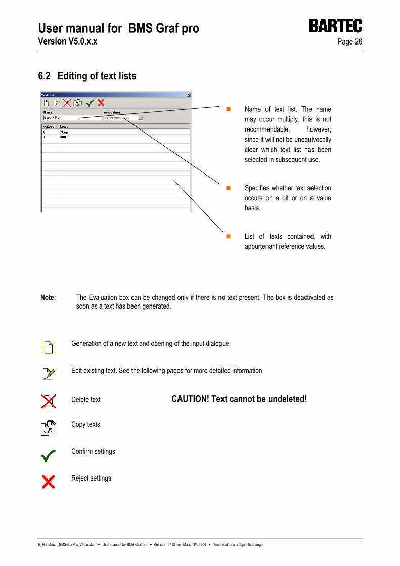
Name of text list. The name may occur multiply, this is not recommendable, however, since it will not be unequivocally clear which text list has been selected in subsequent use.
Specifies whether text selection occurs on a bit or on a value basis.
List of texts contained, with appurtenant reference values.
Note: The Evaluation box can be changed only if there is no text present. The box is deactivated as soon as a text has been generated.
Generation of a new text and opening of the input dialogue
Edit existing text. See the following pages for more detailed information
Delete text CAUTION! Text cannot be undeleted!
Copy texts
Confirm settings
Reject settings

User manual for BMS Graf pro Version V5.0.x.x Page 27
E_Handbuch_BMSGrafPro_V50xx.doc • User manual for BMS Graf pro • Revision 1 / Status: March 8th, 2004 • Technical data subject to change
6.2.1 Bit–oriented list text
State here the bit to which the text is to be linked The text which is to be shown subsequently
Confirm settings
Reject settings
6.2.2 Value-oriented list text
State here the value which the text is to be linked
The text which is to be shown subsequently
Confirm settings
Reject settings
User manual for BMS Graf pro Version V5.0.x.x Page 28
E_Handbuch_BMSGrafPro_V50xx.doc • User manual for BMS Graf pro • Revision 1 / Status: March 8th, 2004 • Technical data subject to change
7 Drafting and editing images
7.1 Images overview
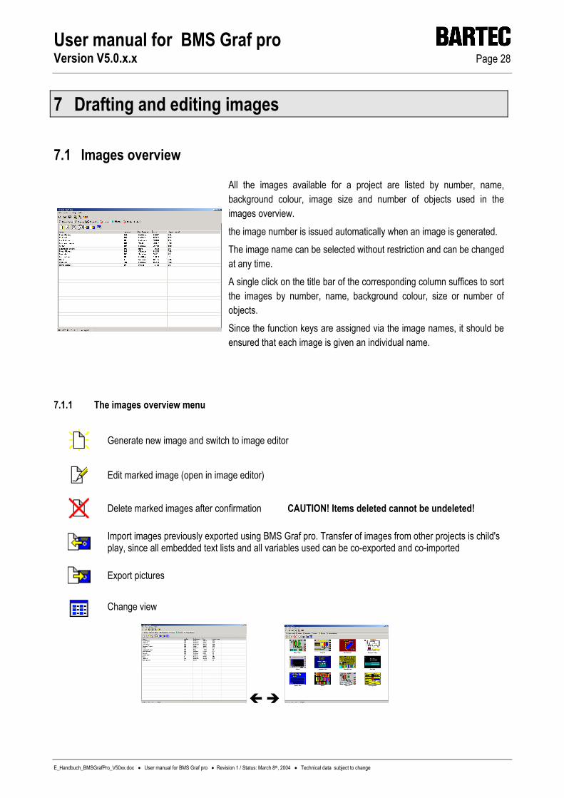
All the images available for a project are listed by number, name, background colour, image size and number of objects used in the images overview. the image number is issued automatically when an image is generated. The image name can be selected without restriction and can be changed at any time. A single click on the title bar of the corresponding column suffices to sort the images by number, name, background colour, size or number of objects. Since the function keys are assigned via the image names, it should be ensured that each image is given an individual name.
7.1.1 The images overview menu
Generate new image and switch to image editor
Edit marked image (open in image editor)
Delete marked images after confirmation CAUTION! Items deleted cannot be undeleted!
Import images previously exported using BMS Graf pro. Transfer of images from other projects is child's play, since all embedded text lists and all variables used can be co-exported and co-imported
Export pictures
Change view

User manual for BMS Graf pro Version V5.0.x.x Page 29
E_Handbuch_BMSGrafPro_V50xx.doc • User manual for BMS Graf pro • Revision 1 / Status: March 8th, 2004 • Technical data subject to change
7.2 The image editor
7.2.1 Overview
Image settings Editing tools Depiction tools Tool bar Object tree Working area Editing line
With a resolution of 1280 x 1024 image points the complete SVGA display of the BAT 800 can be represented and processed in the editor field.
7.2.2 Tool bar
7.2.2.1 The selection arrow
Individual objects can be selected using a mouse click. Objects can be moved and/or made larger/smaller. A number of objects can be selected by dragging a window. The mouse cursor changes depending on the function selected.

User manual for BMS Graf pro Version V5.0.x.x Page 30
E_Handbuch_BMSGrafPro_V50xx.doc • User manual for BMS Graf pro • Revision 1 / Status: March 8th, 2004 • Technical data subject to change
7.2.2.2 The symbol functions
Draw a line from the first mouse click to the second mouse click
Generates a rectangle
Generates a circle with the first mouse click as its center point
Draws a polygon. The second mouse click at the same point or at the starting point closes the polygon
7.2.2.3 Editing texts
Entry line: Enter the text to be displayed here Select here the character set in which the text is to be displayed The text will be displayed in original size in the Preview window
Confirm settings
Reject settings The position in the image can be selected by means of a further mouse click on the working area
User manual for BMS Graf pro Version V5.0.x.x Page 31
E_Handbuch_BMSGrafPro_V50xx.doc • User manual for BMS Graf pro • Revision 1 / Status: March 8th, 2004 • Technical data subject to change
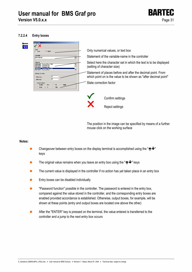
7.2.2.4 Entry boxes
Only numerical values, or text box Statement of the variable-name in the controller Select here the character set in which the text is to be displayed (setting of character size) Statement of places before and after the decimal point. From which point on is the value to be shown as "after decimal point" State correction factor
Confirm settings
Reject settings The position in the image can be specified by means of a further mouse click on the working surface
Notes:
Changeover between entry boxes on the display terminal is accomplished using the " " keys
The original value remains when you leave an entry box using the " " keys
The current value is displayed in the controller if no action has yet taken place in an entry box
Entry boxes can be disabled individually
"Password function" possible in the controller. The password is entered in the entry box, compared against the value stored in the controller, and the corresponding entry boxes are enabled provided accordance is established. Otherwise, output boxes, for example, will be shown at these points (entry and output boxes are located one above the other)
After the "ENTER" key is pressed on the terminal, the value entered is transferred to the controller and a jump to the next entry box occurs

User manual for BMS Graf pro Version V5.0.x.x Page 32
E_Handbuch_BMSGrafPro_V50xx.doc • User manual for BMS Graf pro • Revision 1 / Status: March 8th, 2004 • Technical data subject to change
7.2.2.5 Output boxes
Only numerical values or text box Statement of the variable-name in the controller Select here the character set in which the text is to be shown (setting of character size) Statement of places for and after the decimal point. From what place is the value to be shown as "after decimal point" Statement of a correction factor
Confirm settings
Reject settings A position in the image can be specified by means of a further mouse click on the working area
Notes:
In the case of Master coupling interface, the current value in the controller is displayed
In the case of Slave coupling interface, the value is updated after every reception

User manual for BMS Graf pro Version V5.0.x.x Page 33
E_Handbuch_BMSGrafPro_V50xx.doc • User manual for BMS Graf pro • Revision 1 / Status: March 8th, 2004 • Technical data subject to change
7.2.2.6 Line writer
Input of the value range which can be depicted Setting of running direction Statement of when a new value is to be adopted from the controller to the line writer Colour of time-axis labeling. Line and background colors via the general colour settings Time-axis labeling Statement of variables for the value range (Y axis) Statement of status variables, e.g. Start curve, Stop curve
Bit number
value Action
0 1 Start 0 Stop 1 1 Delete 0 Non
Confirm settings
Reject settings The position in the image can be specified by means of a further mouse click on the working area
Notes :
The line-writers are positioned by the first mouse click and their size changed by dragging up to the second mouse click
Statement of a fixed labeling for the Y axis has been omitted, in order to permit individual utilization of line-writers. The labeling must be drafted using text input for each specific application
A number of line-writers can be positioned on top of one another at the same point
All the line-writers contained in the project are also written in the background, i.e., even if the image is not visible
A maximum of ten line-writers can be entered per project, for storage capacity and speed reasons
Colour changes can be implemented by means of line-writers located vertically above one another
Example: First line-writer, in green, from value range 0 to 50, second line-writer with the same variables in red, from 50 to 100

User manual for BMS Graf pro Version V5.0.x.x Page 34
E_Handbuch_BMSGrafPro_V50xx.doc • User manual for BMS Graf pro • Revision 1 / Status: March 8th, 2004 • Technical data subject to change
7.2.2.7 Bar graphs
Statement of variables for the value range Input of the depictable value range Setting of running direction
Confirm settings
Reject settings
Notes:
Statement of a fixed scaling labeling has been omitted here, in order to permit individual utilization of the bar graphs. The bar graph labeling must be created using text input for each application
The bar graphs can be positioned using the first mouse click and their size changed by dragging up to the second mouse click
Colour changes can be implemented by means of bar graphs located vertically one on top of the other
Example: First bar graph, in green, from value range 0 to 50, second bar graph with the same variables in red from 50 to 100
User manual for BMS Graf pro Version V5.0.x.x Page 36
E_Handbuch_BMSGrafPro_V50xx.doc • User manual for BMS Graf pro • Revision 1 / Status: March 8th, 2004 • Technical data subject to change
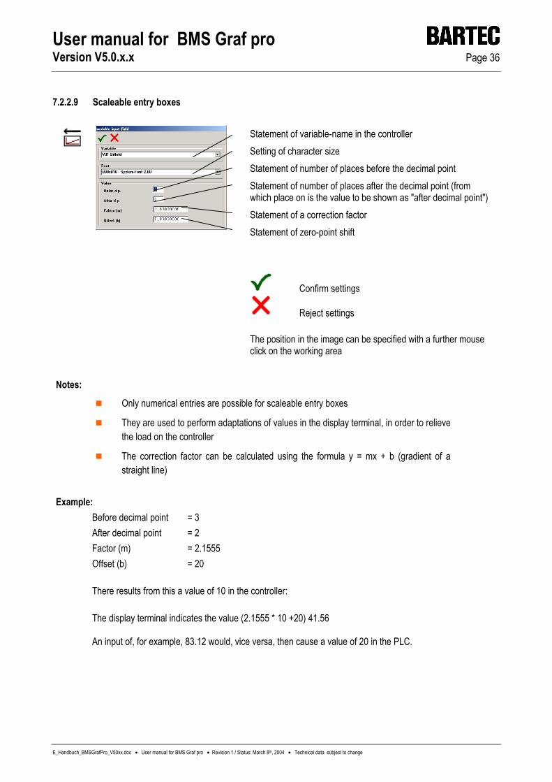
7.2.2.9 Scaleable entry boxes
Statement of variable-name in the controller Setting of character size Statement of number of places before the decimal point Statement of number of places after the decimal point (from which place on is the value to be shown as "after decimal point") Statement of a correction factor Statement of zero-point shift
Confirm settings
Reject settings The position in the image can be specified with a further mouse click on the working area
Notes:
Only numerical entries are possible for scaleable entry boxes
They are used to perform adaptations of values in the display terminal, in order to relieve the load on the controller
The correction factor can be calculated using the formula y = mx + b (gradient of a straight line)
Example: Before decimal point = 3 After decimal point = 2 Factor (m) = 2.1555 Offset (b) = 20 There results from this a value of 10 in the controller: The display terminal indicates the value (2.1555 * 10 +20) 41.56 An input of, for example, 83.12 would, vice versa, then cause a value of 20 in the PLC.

User manual for BMS Graf pro Version V5.0.x.x Page 36
E_Handbuch_BMSGrafPro_V50xx.doc • User manual for BMS Graf pro • Revision 1 / Status: March 8th, 2004 • Technical data subject to change
7.2.2.9 Scaleable entry boxes
Statement of variable-name in the controller Setting of character size Statement of number of places before the decimal point Statement of number of places after the decimal point (from which place on is the value to be shown as "after decimal point") Statement of a correction factor Statement of zero-point shift
Confirm settings
Reject settings The position in the image can be specified with a further mouse click on the working area
Notes:
Only numerical entries are possible for scaleable entry boxes
They are used to perform adaptations of values in the display terminal, in order to relieve the load on the controller
The correction factor can be calculated using the formula y = mx + b (gradient of a straight line)
Example: Before decimal point = 3 After decimal point = 2 Factor (m) = 2.1555 Offset (b) = 20 There results from this a value of 10 in the controller: The display terminal indicates the value (2.1555 * 10 +20) 41.56 An input of, for example, 83.12 would, vice versa, then cause a value of 20 in the PLC.
User manual for BMS Graf pro Version V5.0.x.x Page 37
E_Handbuch_BMSGrafPro_V50xx.doc • User manual for BMS Graf pro • Revision 1 / Status: March 8th, 2004 • Technical data subject to change
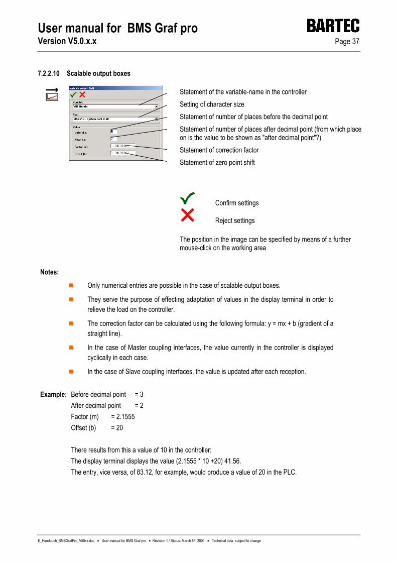
7.2.2.10 Scalable output boxes
Statement of the variable-name in the controller Setting of character size Statement of number of places before the decimal point Statement of number of places after decimal point (from which place on is the value to be shown as "after decimal point"?) Statement of correction factor Statement of zero point shift
Confirm settings
Reject settings The position in the image can be specified by means of a further mouse-click on the working area
Notes:
Only numerical entries are possible in the case of scalable output boxes.
They serve the purpose of effecting adaptation of values in the display terminal in order to relieve the load on the controller.
The correction factor can be calculated using the following formula: y = mx + b (gradient of a straight line).
In the case of Master coupling interfaces, the value currently in the controller is displayed cyclically in each case.
In the case of Slave coupling interfaces, the value is updated after each reception.
Example: Before decimal point = 3 After decimal point = 2 Factor (m) = 2.1555 Offset (b) = 20 There results from this a value of 10 in the controller: The display terminal displays the value (2.1555 * 10 +20) 41.56.
The entry, vice versa, of 83.12, for example, would produce a value of 20 in the PLC.

User manual for BMS Graf pro Version V5.0.x.x Page 38
E_Handbuch_BMSGrafPro_V50xx.doc • User manual for BMS Graf pro • Revision 1 / Status: March 8th, 2004 • Technical data subject to change
7.2.2.11 Date output box
Setting of character size Setting of depiction type State decimal dividing character ("point" is the default setting) Formatting of output string
Confirm settings
Reject settings The position in the image can be specified by means of a further mouse click of the working area
7.2.2.12 Time output box
Setting of character size Setting of depiction type
State decimal dividing character ("point" is the default character) Formatting of output string
Confirm settings
Reject settings The position in the image can be specified by means of a further mouse click on the working area

User manual for BMS Graf pro Version V5.0.x.x Page 39
E_Handbuch_BMSGrafPro_V50xx.doc • User manual for BMS Graf pro • Revision 1 / Status: March 8th, 2004 • Technical data subject to change
7.2.2.13 Text-lists output
Statement of variable-name in the controller Setting of depiction type Selection of the text list previously generated
Confirm settings
Reject settings The position can be specified by means of a further mouse click on the working area
Notes:
The text-lists output is used for depiction of various texts at the same point
The length of the text box depends on the longest text used. The "No background" background colour should not be selected
Where the variable contains a value which is not contained in the list (no text), an empty box of the length of the longest text and with the selected background colour will be depicted
A text-list box may contain a maximum of 200 texts
Toggling between value and bit oriented is no longer possible if texts are already present Example: The variable in the controller contains the value 2, the display terminal depicts the "AUTO" text The variable in the controller contains the value 0, the display terminal depicts the "OFF" text The variable in the controller contains the value 5, the display terminal depicts the empty text " ".

User manual for BMS Graf pro Version V5.0.x.x Page 40
E_Handbuch_BMSGrafPro_V50xx.doc • User manual for BMS Graf pro • Revision 1 / Status: March 8th, 2004 • Technical data subject to change
7.2.2.14 Text-lists entry
Selection of a range of pre-defined texts at entry. See Text-lists Output for settings.
Statement of the variable-name in the controller Setting of depiction type Selection of the text list previously generated
Confirm settings
Reject settings The position in the image can be specified by means of a further mouse click on the working area
Notes:
The Text List Entry is used for depiction of various texts at the same entry point
The length of the text box depends on the longest text present. The "No background" background colour should not be selected
Changeover between all entry boxes on the terminal is accomplished using the " " keys
One of the pre-defined texts should be selected using the " " keys
After actuation of the "ENTER" key on the terminal, the value corresponding to the text is transferred to the controller and a jump to the next entry box occurs
The original value is retained if you leave an entry box in the" " keys
Where the variable contains a value which is not contained in the list (no text present), an empty box with the length of the longest text and the selected background colour is shown (non-selected entry boxes represent the current value in the controller)
A text-list box may contain a maximum of 200 texts

User manual for BMS Graf pro Version V5.0.x.x Page 41
E_Handbuch_BMSGrafPro_V50xx.doc • User manual for BMS Graf pro • Revision 1 / Status: March 8th, 2004 • Technical data subject to change
7.2.2.15 Embed bit map
Integration of a standard BMP file.
Keep the original size. After integration the size of the object can no longer be changed. Activate transparent representation Preview of BMP file Selected colour, which is to be represented as transparent For easier selection the colour under the mouse cursor
Settings have been taken over
Settings have not been taken over
Open BMP file
With a further mouse click on the working area you establish the position in the image.
Comments: The object can embed BMP files in itself. JPG, TIF, GIF and other formats cannot be
integrated. However, with commonly commercially available image processing programmes it is easily possible to store other graphics formats as Windows BMP.
For minimum storage requirements BMSs should be used several times in the same size and alignment, instead of in different sizes and/or alignments, since then only one copy is loaded in the terminal.
Embedded BMSs with less than 16 bit depth of colour cause a false colour image with some graphics drivers of individual graphics cards under Windows 2000 and Windows XP. Remedy: Convert the image into the 16 bit or 24 bit colour mode and safeguard this with a commercially available programme (e.g. paintbrush).
When embedding BMSs please bear in mind the maximum memory space of the terminal.
User manual for BMS Graf pro Version V5.0.x.x Page 42
E_Handbuch_BMSGrafPro_V50xx.doc • User manual for BMS Graf pro • Revision 1 / Status: March 8th, 2004 • Technical data subject to change
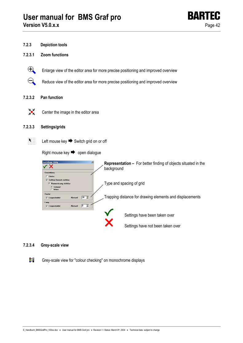
7.2.3 Depiction tools
7.2.3.1 Zoom functions
Enlarge view of the editor area for more precise positioning and improved overview
Reduce view of the editor area for more precise positioning and improved overview
7.2.3.2 Pan function
Center the image in the editor area
7.2.3.3 Settings/grids
Left mouse key Switch grid on or off
Right mouse key open dialogue
Representation – For better finding of objects situated in the background Type and spacing of grid Trapping distance for drawing elements and displacements
Settings have been taken over
Settings have not been taken over
7.2.3.4 Grey-scale view
Grey-scale view for "colour checking" on monochrome displays

User manual for BMS Graf pro Version V5.0.x.x Page 43
E_Handbuch_BMSGrafPro_V50xx.doc • User manual for BMS Graf pro • Revision 1 / Status: March 8th, 2004 • Technical data subject to change
7.2.3.5 Settings/copying/mirror-imaging/rotating
Where is a copy to be positioned? How is mirror-imaging to take place? How is rotation to take place?
Confirm settings
Reject settings
7.2.3.6 Scale view
Activate/deactivate scales
7.2.3.7 Object tree
Activate/deactivate window for the object tree The object tree is described a few pages further on

User manual for BMS Graf pro Version V5.0.x.x Page 44
E_Handbuch_BMSGrafPro_V50xx.doc • User manual for BMS Graf pro • Revision 1 / Status: March 8th, 2004 • Technical data subject to change
7.2.4 Editing tools
7.2.4.1 Grouping/separating
An area should be created using the mouse. The objects selected in this way are assembled to form a group
Separates an existing group
7.2.4.2 Foreground/background
The object selected is moved one position forward
The object selected is moved one position backward
The object selected is moved to the front
The object selected is moved to the back
7.2.4.3 Copying
The object or group selected is copied in accordance with the settings
7.2.4.4 Mirror-imaging
The object or group selected is mirror-imaged in accordance with the settings
7.2.4.5 Rotate
The object or group is rotated in accordance with the settings
User manual for BMS Graf pro Version V5.0.x.x Page 45
E_Handbuch_BMSGrafPro_V50xx.doc • User manual for BMS Graf pro • Revision 1 / Status: March 8th, 2004 • Technical data subject to change
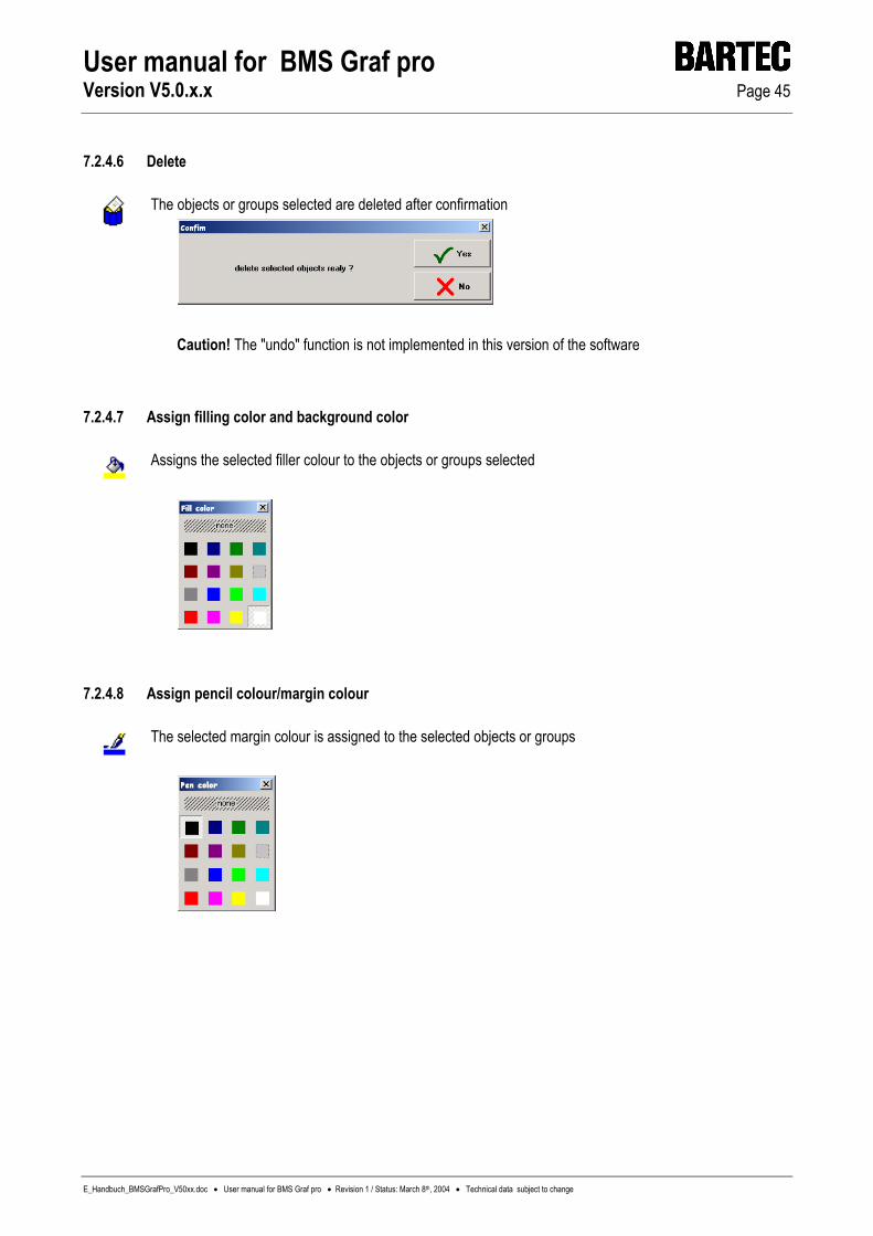
7.2.4.6 Delete
The objects or groups selected are deleted after confirmation
Caution! The "undo" function is not implemented in this version of the software
7.2.4.7 Assign filling color and background color
Assigns the selected filler colour to the objects or groups selected
7.2.4.8 Assign pencil colour/margin colour
The selected margin colour is assigned to the selected objects or groups
User manual for BMS Graf pro Version V5.0.x.x Page 46
E_Handbuch_BMSGrafPro_V50xx.doc • User manual for BMS Graf pro • Revision 1 / Status: March 8th, 2004 • Technical data subject to change
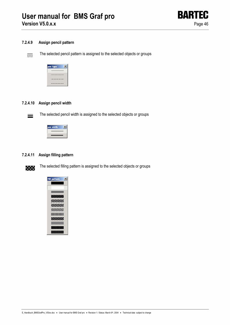
7.2.4.9 Assign pencil pattern
The selected pencil pattern is assigned to the selected objects or groups
7.2.4.10 Assign pencil width
The selected pencil width is assigned to the selected objects or groups
7.2.4.11 Assign filling pattern
The selected filling pattern is assigned to the selected objects or groups

User manual for BMS Graf pro Version V5.0.x.x Page 47
E_Handbuch_BMSGrafPro_V50xx.doc • User manual for BMS Graf pro • Revision 1 / Status: March 8th, 2004 • Technical data subject to change
7.2.5 Image settings
7.2.5.1 Assign basic image data
The image name is used for identification of the image during project development The PLC will select the images in the terminal using the image number The background for the image can be selected here
Confirm settings
Reject settings
User manual for BMS Graf pro Version V5.0.x.x Page 48
E_Handbuch_BMSGrafPro_V50xx.doc • User manual for BMS Graf pro • Revision 1 / Status: March 8th, 2004 • Technical data subject to change
7.2.5.2 Key assignments
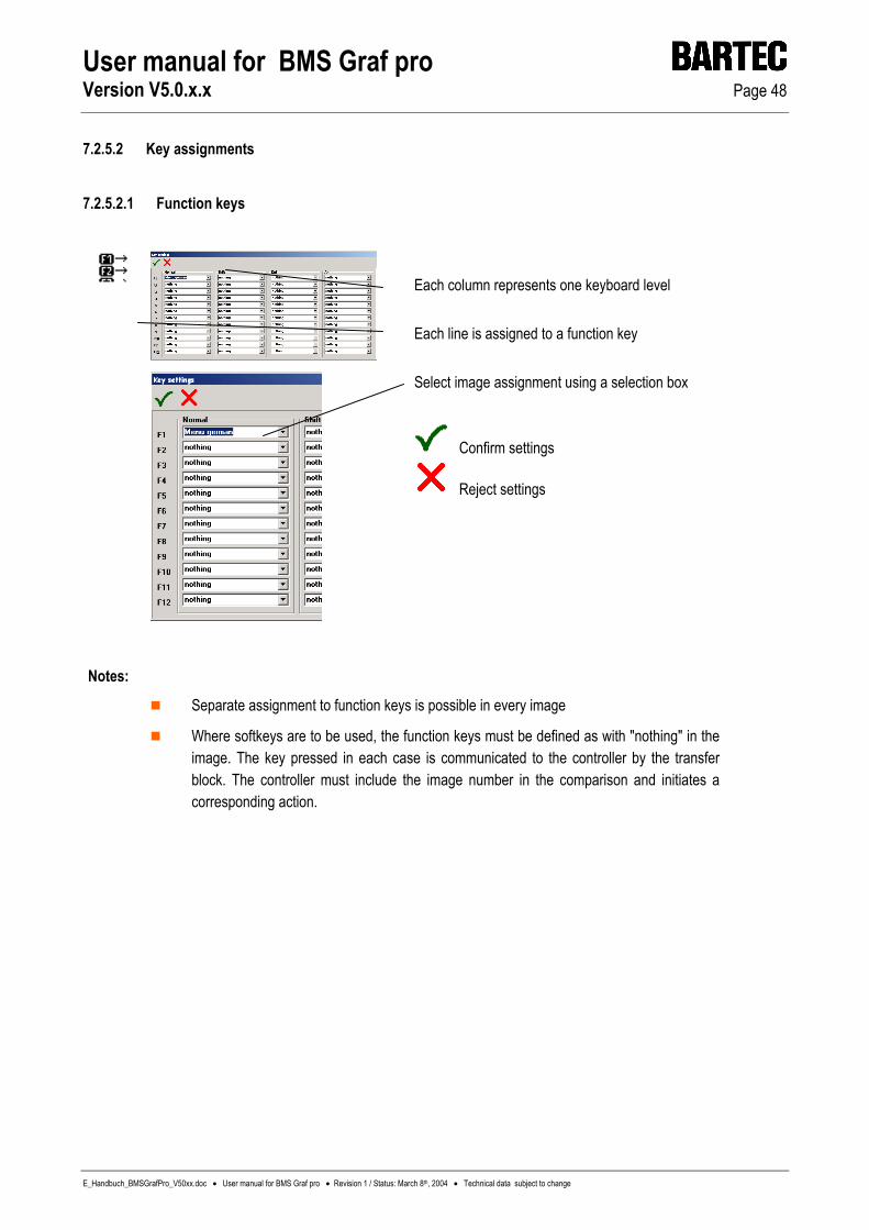
7.2.5.2.1 Function keys
Each column represents one keyboard level Each line is assigned to a function key Select image assignment using a selection box
Confirm settings
Reject settings
Notes:
Separate assignment to function keys is possible in every image
Where softkeys are to be used, the function keys must be defined as with "nothing" in the image. The key pressed in each case is communicated to the controller by the transfer block. The controller must include the image number in the comparison and initiates a corresponding action.
User manual for BMS Graf pro Version V5.0.x.x Page 49
E_Handbuch_BMSGrafPro_V50xx.doc • User manual for BMS Graf pro • Revision 1 / Status: March 8th, 2004 • Technical data subject to change
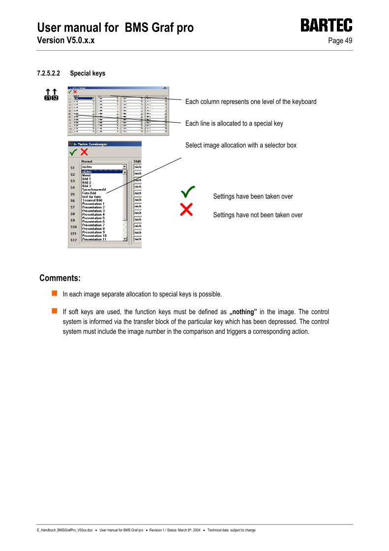
7.2.5.2.2 Special keys
Each column represents one level of the keyboard Each line is allocated to a special key
Select image allocation with a selector box
Settings have been taken over
Settings have not been taken over
Comments: In each image separate allocation to special keys is possible.
If soft keys are used, the function keys must be defined as „nothing” in the image. The control system is informed via the transfer block of the particular key which has been depressed. The control system must include the image number in the comparison and triggers a corresponding action.

User manual for BMS Graf pro Version V5.0.x.x Page 50
E_Handbuch_BMSGrafPro_V50xx.doc • User manual for BMS Graf pro • Revision 1 / Status: March 8th, 2004 • Technical data subject to change
7.2.5.3 Symbol library
A symbol library, containing elements needed repeatedly, can be created here
Objects selected will be saved. Where a number of objects are to be saved, they must be grouped prior to saving Where no element is selected, a selection of the symbols already stored is loaded. The object selected here is positioned on the screen and can then be moved to any position required
Confirm settings
Reject settings
Deletes a symbol from the library after confirmation
Notes:
Where symbols of an old type have been inserted, the variables must be redefined. Any references necessary may be open or contain incorrect assignments
New-type symbols incorporate the necessary variables. Where corresponding variables are available, they will be used. Where no corresponding variables are available, the incorporated variables will be generated in the project
New-type symbols incorporate the necessary text lists. Where corresponding text lists are available, they will be used. Where no corresponding text lists are available, the imported text lists will be generated in the project
User manual for BMS Graf pro Version V5.0.x.x Page 51
E_Handbuch_BMSGrafPro_V50xx.doc • User manual for BMS Graf pro • Revision 1 / Status: March 8th, 2004 • Technical data subject to change
7.3 Object tree
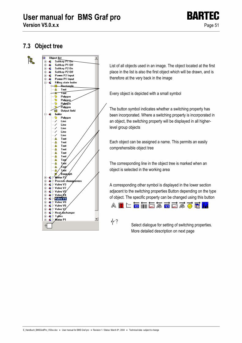
List of all objects used in an image. The object located at the first place in the list is also the first object which will be drawn, and is therefore at the very back in the image Every object is depicted with a small symbol The button symbol indicates whether a switching property has been incorporated. Where a switching property is incorporated in an object, the switching property will be displayed in all higher-level group objects Each object can be assigned a name. This permits an easily comprehensible object tree The corresponding line in the object tree is marked when an object is selected in the working area A corresponding other symbol is displayed in the lower section adjacent to the switching properties Button depending on the type of object. The specific property can be changed using this button
Select dialogue for setting of switching properties. More detailed description on next page

User manual for BMS Graf pro Version V5.0.x.x Page 52
E_Handbuch_BMSGrafPro_V50xx.doc • User manual for BMS Graf pro • Revision 1 / Status: March 8th, 2004 • Technical data subject to change
7.4 Assignment of actions to objects
Every object can be activated with a switching property No action. Actions assigned can be deleted. CAUTION! All the objects contained will be reset (to "None") if this function is used on group objects Bit-orientated action State process link Check for 0 or 1 Select bit. Selection of a number of bits simultaneously is not possible Value-orientated action State process link Reference value Type of check
Confirm settings
Reject settings Notes:
If the switching condition is not fulfilled, objects are not deleted. Another object must be positioned over it for deletion of objects (e.g. a rectangle in screen colour)
Where a switching function is assigned to a group, the switching function is assigned to all of the objects in the group. Switching functions and assignments already existing in the group are overwritten
Example
Colour changes on pipes:
Draw pipe in red from polygon elements
Copy pipe without moving it, colour it green
Reaction to the value "0" is allocated to the red pipe in a variable in Bit 0
The value "1" is assigned to the green pipe in the same bit
A switching function can be assigned to every object
The object is shown if the switching function is fulfilled

User manual for BMS Graf pro Version V5.0.x.x Page 53
E_Handbuch_BMSGrafPro_V50xx.doc • User manual for BMS Graf pro • Revision 1 / Status: March 8th, 2004 • Technical data subject to change
8 Transfer project to the display terminal
Select the COM interface on the PC. Only those interfaces which are indicated as enabled by the operating system can be selected Set the Baud rate. A Baud rate of above 57600 bps is not recommendable on the BAT2 and BAT VGA, since the total time for project transfer will increase as a result of greater incidence of transmission errors Enter terminal number. Each terminal features a number, by means of which it can be unequivocally addressed in a network. The number "1" is the default value set at delivery, but can be changed at any time
There is an increase in volume of the data which have to be transferred to the terminal, caused through the bit maps. For this reason a variant of the download is included with this version, which transfers only the changes in the project.
Start transfer
Abort transfer Notes:
For transfers via a TTY interface a baud rate of less than 19200 bps can be necessary, since the transfer quality is impaired partly through some interface converters and partly through the line length.
For reasons connected with Windows conditions, access to the control line is no longer possible. Thus it is imporssible to operate interface converters, which require selection via RTS/CTS or DTR/DSR. This means that when interface converters (RS232 to RS485), without automatic transmission or receiving changeover, are used, NO download can be carried out.
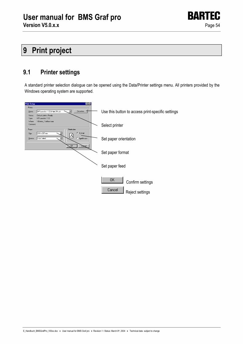
User manual for BMS Graf pro Version V5.0.x.x Page 54
E_Handbuch_BMSGrafPro_V50xx.doc • User manual for BMS Graf pro • Revision 1 / Status: March 8th, 2004 • Technical data subject to change
9 Print project
9.1 Printer settings
A standard printer selection dialogue can be opened using the Data/Printer settings menu. All printers provided by the Windows operating system are supported.
Use this button to access print-specific settings Select printer Set paper orientation Set paper format Set paper feed
Confirm settings
Reject settings
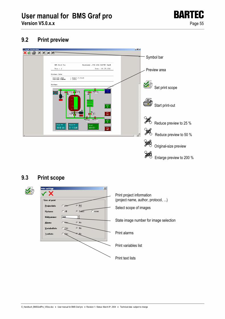
User manual for BMS Graf pro Version V5.0.x.x Page 55
E_Handbuch_BMSGrafPro_V50xx.doc • User manual for BMS Graf pro • Revision 1 / Status: March 8th, 2004 • Technical data subject to change
9.2 Print preview
Symbol bar Preview area
Set print scope
Start print-out
Reduce preview to 25 %
Reduce preview to 50 %
Original-size preview
Enlarge preview to 200 %
9.3 Print scope
Print project information (project name, author, protocol, ...)
Select scope of images State image number for image selection Print alarms Print variables list Print text lists

User manual for BMS Graf pro Version V5.0.x.x Page 56
E_Handbuch_BMSGrafPro_V50xx.doc • User manual for BMS Graf pro • Revision 1 / Status: March 8th, 2004 • Technical data subject to change
Notice:

User manual for BMS Graf pro Version 5.0.x.x Page 57
E_Handbuch_BMSGrafPro_V50xx_AnhangA.doc • User manual for BMS Graf pro • Revision 1 / Status: March 8th, 2004 • Technical data subject to change
Appendix A

User manual for BMS Graf pro Version 5.0.x.x Page 58
E_Handbuch_BMSGrafPro_V50xx_AnhangA.doc • User manual for BMS Graf pro • Revision 1 / Status: March 8th, 2004 • Technical data subject to change
Appendix A
A1. Configuration “SETUP” of the PC Terminal ............................................................................................60
A2. Configuration during operation ................................................................................................................61 A2.1 Menu item >> Set Contrast <<................................................................ 61 A2.2 Menu item >> Start Download <<................................................................ 62 A2.3 Menu item >> Password <<................................................................ 62 A2.4 Menu item >> Set Time/Date <<................................................................ 62 A2.5 Menu item >> COM Port Settings <<................................................................ 63 A2.5.1 PLC settings ............................................................................................................................................... 63 A2.5.2 Barcode Parameter..................................................................................................................................... 64 A2.5.3 Printer settings............................................................................................................................................ 64 A2.6 Menu item >> Language <<................................................................ 64 A2.7 Menu item >> History <<................................................................ 65
A3. Siemens 3964R Interpreter with RK512....................................................................................................66 A3.1 Settings and configuration of control unit S5 with CP 544.......................................................................... 66 A3.1.1 CP544 connection diagram with TTY plug-in card (6ES5752-0AA12) ....................................................... 66 A3.1.2 CP544 connection diagram with RS422/485 plug-in card (6ES5752-0AA43) ............................................ 67 A3.2 Special notes .............................................................................................................................................. 67 A3.3 COM port settings....................................................................................................................................... 67 A3.4 Error messages .......................................................................................................................................... 68 A3.4.1 Possible error messages ............................................................................................................................ 68
A4. Interpreter: Siemens S5 PG port ...............................................................................................................69 A4.1 SPC configuration settings ......................................................................................................................... 69 A4.1.1 Connection diagrams.................................................................................................................................. 69 A4.2 Special notes .............................................................................................................................................. 70 A4.3 COM port settings....................................................................................................................................... 70 A4.4 Error messages .......................................................................................................................................... 71 A4.4.1 Possible error messages ............................................................................................................................ 71
A5. MODBUS RTU connection.........................................................................................................................72 A5.1 Modbus function codes in use .................................................................................................................... 72 A5.1.1 Function code 3: “READ HOLDING REGISTERS“ .................................................................................... 72 A5.1.2 Function code 16: “PRESET MULTIPLE REGISTERS”............................................................................. 73 A5.2 Special notes .............................................................................................................................................. 73 A5.3 Description of the MODBUS RTU interpreters (masters) ........................................................................... 74 A5.3.1 MODBUS RTU interpreter (master) at the address “40001” ...................................................................... 74 A5.3.2 MODBUS RTU interpreter (master) at the address “0” .............................................................................. 74 A5.4 Description of the MODBUS RTU interpreters (slaves).............................................................................. 74 A5.4.1 MODBUS RTU interpreter (slave) at the address “40001” ......................................................................... 74 A5.4.2 MODBUS RTU interpreter (slave) with the address “0”.............................................................................. 75 A5.5 COM port settings....................................................................................................................................... 75 A5.6 Error messages .......................................................................................................................................... 76 A5.6.1 Possible error messages: ........................................................................................................................... 76
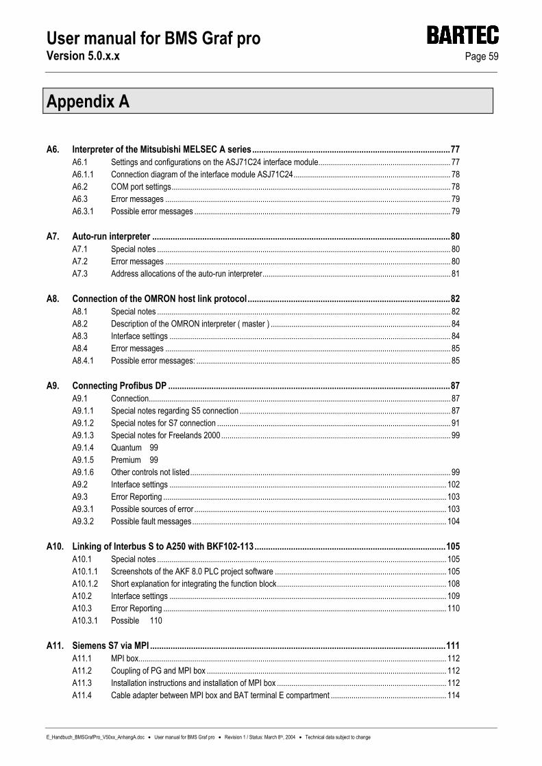
User manual for BMS Graf pro Version 5.0.x.x Page 59
E_Handbuch_BMSGrafPro_V50xx_AnhangA.doc • User manual for BMS Graf pro • Revision 1 / Status: March 8th, 2004 • Technical data subject to change
Appendix A
A6. Interpreter of the Mitsubishi MELSEC A series.......................................................................................77 A6.1 Settings and configurations on the ASJ71C24 interface module................................................................ 77 A6.1.1 Connection diagram of the interface module ASJ71C24............................................................................ 78 A6.2 COM port settings....................................................................................................................................... 78 A6.3 Error messages .......................................................................................................................................... 79 A6.3.1 Possible error messages ............................................................................................................................ 79
A7. Auto-run interpreter ...................................................................................................................................80 A7.1 Special notes .............................................................................................................................................. 80 A7.2 Error messages .......................................................................................................................................... 80 A7.3 Address allocations of the auto-run interpreter........................................................................................... 81
A8. Connection of the OMRON host link protocol.........................................................................................82 A8.1 Special notes .............................................................................................................................................. 82 A8.2 Description of the OMRON interpreter ( master ) ....................................................................................... 84 A8.3 Interface settings ........................................................................................................................................ 84 A8.4 Error messages .......................................................................................................................................... 85 A8.4.1 Possible error messages: ........................................................................................................................... 85
A9. Connecting Profibus DP ............................................................................................................................87 A9.1 Connection.................................................................................................................................................. 87 A9.1.1 Special notes regarding S5 connection ...................................................................................................... 87 A9.1.2 Special notes for S7 connection ................................................................................................................. 91 A9.1.3 Special notes for Freelands 2000............................................................................................................... 99 A9.1.4 Quantum 99 A9.1.5 Premium 99 A9.1.6 Other controls not listed.............................................................................................................................. 99 A9.2 Interface settings ...................................................................................................................................... 102 A9.3 Error Reporting ......................................................................................................................................... 103 A9.3.1 Possible sources of error .......................................................................................................................... 103 A9.3.2 Possible fault messages........................................................................................................................... 104
A10. Linking of Interbus S to A250 with BKF102-113....................................................................................105 A10.1 Special notes ............................................................................................................................................ 105 A10.1.1 Screenshots of the AKF 8.0 PLC project software ................................................................................... 105 A10.1.2 Short explanation for integrating the function block.................................................................................. 108 A10.2 Interface settings ...................................................................................................................................... 109 A10.3 Error Reporting ......................................................................................................................................... 110 A10.3.1 Possible 110
A11. Siemens S7 via MPI ..................................................................................................................................111 A11.1 MPI box..................................................................................................................................................... 112 A11.2 Coupling of PG and MPI box .................................................................................................................... 112 A11.3 Installation instructions and installation of MPI box .................................................................................. 112 A11.4 Cable adapter between MPI box and BAT terminal E compartment ........................................................ 114

User manual for BMS Graf pro Version 5.0.x.x Page 60
E_BMSGrafPro_V50xx_AnhangA.doc • User manual for BMS Graf pro • Revision 1 / Status: March 8th, 2004 • Technical data subject to change
A1. Configuration “SETUP” of the PC Terminal
Please look at the installations manual.

User manual for BMS Graf pro Version 5.0.x.x Page 61
E_BMSGrafPro_V50xx_AnhangA.doc • User manual for BMS Graf pro • Revision 1 / Status: March 8th, 2004 • Technical data subject to change
A2. Configuration during operation
To set up the system during operation, press “i”. It is similar to the previous setup. If error messages are available, then these are displayed first. Press “i” again to proceed with the setup.
The purpose of this setup is to adapt the interpreter to the relevant control unit.
A2.1 Menu item >> Set Contrast <<
Press to change the contrast. While is being pressed, the PC display terminal will get darker at first, and then brighter again. As soon as you have reached the desired contrast, either press ENTER to save the current contrast value or ESC to revert to the original contrast settings.
Important: Keep down until the all the details on the screen are visible again, otherwise you will be saving a contrast that is too dark.

User manual for BMS Graf pro Version 5.0.x.x Page 62
E_BMSGrafPro_V50xx_AnhangA.doc • User manual for BMS Graf pro • Revision 1 / Status: March 8th, 2004 • Technical data subject to change
A2.2 Menu item >> Start Download << Choose this menu item to manually start the download program of the PC display terminal.
After a password query the interpreter is closed and the main setup is started. In the main setup, choose “Start Download” again. (The main setup closes after 5 seconds, and the interpreter starts again).
A2.3 Menu item >> Password <<
All menu items, apart from the contrast settings, are protected against unauthorised use by a password. This is where you can change the password.
A2.4 Menu item >> Set Time/Date <<
This is where you can change the system time and date of the PC display terminal.

User manual for BMS Graf pro Version 5.0.x.x Page 63
E_BMSGrafPro_V50xx_AnhangA.doc • User manual for BMS Graf pro • Revision 1 / Status: March 8th, 2004 • Technical data subject to change
A2.5 Menu item >> COM Port Settings <<
From version 2.60, the COM ports are allocated to certain devices. Press ENTER to change the settings for each port.
A2.5.1 PLC settings
Some of these settings are dependent on the interpreter that is in use. If you use the S5-PG Mode interpreter, for instance, you cannot change the COM port settings, because they have been fixed by Siemens.
Select the port for the control unit and the download.
Select the port for a bar code scanner.
Select the port for a serial printer.

User manual for BMS Graf pro Version 5.0.x.x Page 64
E_BMSGrafPro_V50xx_AnhangA.doc • User manual for BMS Graf pro • Revision 1 / Status: March 8th, 2004 • Technical data subject to change
A2.5.2 Barcode Parameter
Enter here the COM port settings for a bar code scanner or a similar device (ASCII characters).
A2.5.3 Printer settings
Enter here the COM port settings for a serial printer. If required, this serial printer can be used for printing the content of the Histogram as a text file.
A2.6 Menu item >> Language <<
This is where you specify the setup language.
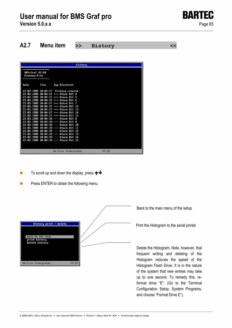
User manual for BMS Graf pro Version 5.0.x.x Page 65
E_BMSGrafPro_V50xx_AnhangA.doc • User manual for BMS Graf pro • Revision 1 / Status: March 8th, 2004 • Technical data subject to change
A2.7 Menu item >> History <<
To scroll up and down the display, press .
Press ENTER to obtain the following menu.
Back to the main menu of the setup
Print the Histogram to the serial printer
Delete the Histogram. Note, however, that frequent writing and deleting of the Histogram reduces the speed of the Histogram Flash Drive. It is in the nature of the system that new entries may take up to one second. To remedy this, re-format drive “E”. (Go to the Terminal Configuration Setup, System Programs, and choose “Format Drive E”).
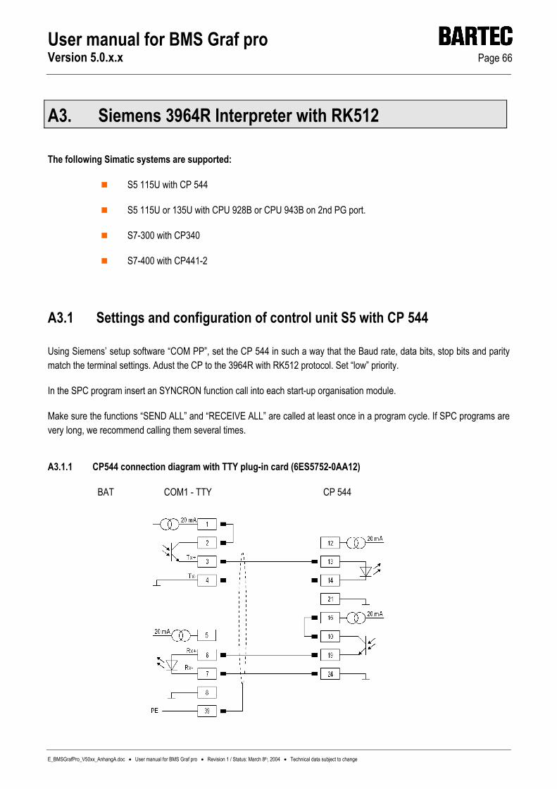
User manual for BMS Graf pro Version 5.0.x.x Page 66
E_BMSGrafPro_V50xx_AnhangA.doc • User manual for BMS Graf pro • Revision 1 / Status: March 8th, 2004 • Technical data subject to change
A3. Siemens 3964R Interpreter with RK512
The following Simatic systems are supported:
S5 115U with CP 544
S5 115U or 135U with CPU 928B or CPU 943B on 2nd PG port.
S7-300 with CP340
S7-400 with CP441-2
A3.1 Settings and configuration of control unit S5 with CP 544
Using Siemens’ setup software “COM PP”, set the CP 544 in such a way that the Baud rate, data bits, stop bits and parity match the terminal settings. Adust the CP to the 3964R with RK512 protocol. Set “low” priority.
In the SPC program insert an SYNCRON function call into each start-up organisation module.
Make sure the functions “SEND ALL” and “RECEIVE ALL” are called at least once in a program cycle. If SPC programs are very long, we recommend calling them several times.
A3.1.1 CP544 connection diagram with TTY plug-in card (6ES5752-0AA12)
BAT COM1 - TTY CP 544

User manual for BMS Graf pro Version 5.0.x.x Page 67
E_BMSGrafPro_V50xx_AnhangA.doc • User manual for BMS Graf pro • Revision 1 / Status: March 8th, 2004 • Technical data subject to change
A3.1.2 CP544 connection diagram with RS422/485 plug-in card (6ES5752-0AA43)
BAT Com 1 - RS422 CP544
A3.2 Special notes
The BMS Graf pro software is independent of the SPC. This means that Siemens’ special “KG” format is not supported.
A3.3 COM port settings
Select the port for the control unit and the download.
Select the port for the control unit and the download.
Select the port for a bar code scanner.
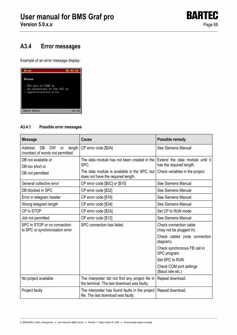
User manual for BMS Graf pro Version 5.0.x.x Page 68
E_BMSGrafPro_V50xx_AnhangA.doc • User manual for BMS Graf pro • Revision 1 / Status: March 8th, 2004 • Technical data subject to change
A3.4 Error messages
Example of an error message display:
A3.4.1 Possible error messages
Message Cause Possible remedy
Address DB DW or length (number) of words not permitted
CP error code [$0A] See Siemens Manual
DB not available or DB too short or DB not permitted
The data module has not been created in the SPC. The data module is available in the SPC, but does not have the required length.
Extend the data module until it has the required length. Check variables in the project.
General collective error CP error code [$0C] or [$10] See Siemens Manual DB blocked in SPC CP error code [$32] See Siemens Manual Error in telegram header CP error code [$16] See Siemens Manual Wrong telegram length CP error code [$34] See Siemens Manual CP in STOP CP error code [$2A] Set CP to RUN mode Job not permitted CP error code [$12] See Siemens Manual SPC in STOP or no connection to SPC or synchronisation error
SPC connection has failed. Check connection cable (may not be plugged in). Check cables (note connection diagram). Check synchronous FB call in SPC program. Set SPC to RUN. Check COM port settings (Baud rate etc.)
No project available The interpreter did not find any project file in the terminal. The last download was faulty.
Repeat download.
Project faulty The interpreter has found faults in the project file. The last download was faulty.
Repeat download.

User manual for BMS Graf pro Version 5.0.x.x Page 69
E_BMSGrafPro_V50xx_AnhangA.doc • User manual for BMS Graf pro • Revision 1 / Status: March 8th, 2004 • Technical data subject to change
A4. Interpreter: Siemens S5 PG port
The following Simatic systems are supported:
S5 90U
S5 95U
S5 115U CPU types 941, 942, 943 and 944
A4.1 SPC configuration settings
No settings are required on the S5 to connect the terminal via the PG port.
A4.1.1 Connection diagrams
Installation to the PG port of the Simatic S5 in general: Installation on the PG port of the Simatic S5 90U:
BAT COM1 - TTY S5 PG –15 Pins
BAT COM1 - TTY S5 PG – 15 Pins

User manual for BMS Graf pro Version 5.0.x.x Page 70
E_BMSGrafPro_V50xx_AnhangA.doc • User manual for BMS Graf pro • Revision 1 / Status: March 8th, 2004 • Technical data subject to change
A4.2 Special notes
When booting up and when plugging in the connection to the PC display terminal, the system reads the address location of variables in the memory of the Siemens SPC system once. Variables are then accessed at the identified addresses. If the memory area of the SPC system is changed (e.g. program change, archiving, etc.), then the addresses no longer match the ones that have been identified, and the variables can no longer be interpreted correctly. Writing operations can even lead to the destruction of the SPC program.
If the memory area of the SPC system has to be manipulated, make sure you first separate the PC display terminal from the control unit.
The BMS Graf pro software is independent of the SPC. This means that Siemens’ special “KG” format is not supported.
A4.3 COM port settings
The interpreter for S5-PG mode does not demand COM port settings, as these settings are fixed and need not and cannot be changed.
Select the port for the control unit and the download.
Select the port for a bar code scanner.
Select the port for a serial printer.

User manual for BMS Graf pro Version 5.0.x.x Page 71
E_BMSGrafPro_V50xx_AnhangA.doc • User manual for BMS Graf pro • Revision 1 / Status: March 8th, 2004 • Technical data subject to change
A4.4 Error messages
Example of an error message display:
A4.4.1 Possible error messages
Message Cause Possible remedy
DB not available The data module has not been created in the SPC.
Create the data module in the SPC.
DB too short Available as far as DW Required as far as DW
The data module is available in the SPC, but does not have the required length.
Extend the data module until it has the required length. Check variables in the project.
Access to DB header data refused or faulty.
Fault in connection. SPC type not known.
Check if cable screen has been set up correctly. Check if there are cables under electric power near the interface line.
Access to DB Accountant refused or faulty
Fault in connection. SPC type not known.
Check if cable screen has been set up correctly. Check if there are cables under electric power near the interface line.
No communication with control unit. SPC connection has failed. Check connection cable (may not be plugged in). Wiring (note TTY connection diagram).
No project available The interpreter did not find any project file in the terminal.
Repeat download.
Project faulty The interpreter has found faults in the project file. The last download was faulty.
Repeat download.

User manual for BMS Graf pro Version 5.0.x.x Page 72
E_BMSGrafPro_V50xx_AnhangA.doc • User manual for BMS Graf pro • Revision 1 / Status: March 8th, 2004 • Technical data subject to change
A5. MODBUS RTU connection
The following connections have already been implemented:
Telemechique TSX series with communications processor TSXSCQ1131
APRIL
AEG A-series with MODBUS module
AEG Modicon with Modbus Plus to Modbus RTU bridge
AEG Quantum
Allen Bradley SLCC500 with Pro Soft module (3150MCM)
Allen Bradley PLC5/40 or PLC5/60 with communications board/module 17-71-DBMM
HIMA H51
HIMA H41
HIMA H11
Yokogawa SMCC Micro XL with communications processor PX1
GE-FANUC with communications processor CMM311E
A5.1 Modbus function codes in use
A5.1.1 Function code 3: “READ HOLDING REGISTERS“
Request:
SLAVE ADDR
FUNC. CODE
DATA START HI
DATA START LO
LEN HI
LEN LO
ERROR CHECK CRC16
ERROR CHECK CRC16
1 3 00 00 00 02 xx xx
Reply:
SLAVE ADDR
FUNC. CODE
BYTE COUNT
HI DATA
LO DATA
HI DATA
LO DATA
ERROR CHECK CRC16
ERROR CHECK CRC16
1 3 04 01 02 03 04 xx xx

User manual for BMS Graf pro Version 5.0.x.x Page 73
E_BMSGrafPro_V50xx_AnhangA.doc • User manual for BMS Graf pro • Revision 1 / Status: March 8th, 2004 • Technical data subject to change
A5.1.2 Function code 16: “PRESET MULTIPLE REGISTERS”
Request:
SLAVE ADDR
FUNC. CODE
DATA START HI
DATA START LO
LEN HI
LEN LO
BYTE CNT
HI DATA
LO DADA
HI DATA
LO DATA
ERROR CHECK CRC16
ERROR CHECK CRC16
1 10 00 00 00 02 04 01 02 03 04 xx xx
Reply:
SLAVE ADDR
FUNC. CODE
DATA STARTHI
DATA STARTLO
LEN HI
LEN LO
ERROR CHECK CRC16
ERROR CHECK CRC16
1 10 00 00 00 02 xx xx
A5.2 Special notes
The MODBUS RTU protocol is very intolerant of errors. If an error occurs due to
the wrong Baud rate, data bit length, parity or stop bits,
the checksum,
the slave or station number,
then the query is not answered. Make sure, therefore, that you check all settings very carefully.
As the settings in the control unit vary widely, depending on the type, we must refer you to the various manufacturers’ manuals at this point.
Do not use the RS 485 port (2-wire technology) for slave systems. As all bus subscribers would be listening at the same time, there may be delays to the timing. If you have a slave system, we therefore recommend RS 422 (with 4-wire technology).

User manual for BMS Graf pro Version 5.0.x.x Page 74
E_BMSGrafPro_V50xx_AnhangA.doc • User manual for BMS Graf pro • Revision 1 / Status: March 8th, 2004 • Technical data subject to change
A5.3 Description of the MODBUS RTU interpreters (masters)
The BMS GRAFpro software has two MODBUS RTU interpreters (masters).
A5.3.1 MODBUS RTU interpreter (master) at the address “40001”
The first MODBUS RTU interpreter (master) has been kept for historical reasons. The address “40001” in BMS Graf pro corresponds to the address “0” in the MODBUS protocol. The address range is defined from “40001” to “49999”. All address range violations are intercepted in the terminal as faulty. Make sure you use the correct address location in the control unit, i.e. consult the relevant control unit manual for the subsequent allocation of a MODBUS address to an address in the control unit.
We recommend that you do not use this interpreter for new projects.
A5.3.2 MODBUS RTU interpreter (master) at the address “0”
This MODBUS RTU interpreter (master) has been developed for better address allocation. The address “00000” in BMS Graf pro, corresponds to “0” in the MODBUS protocol. The address range is defined from “00000” to “65535”. Make sure you use the correct address location in the control unit, i.e. consult the relevant control unit manual for the subsequent allocation of a MODBUS address to an address in the control unit. You also need to ensure that the addresses of your variables are within a narrow range, to avoid too many time-consuming read/write operations.
A5.4 Description of the MODBUS RTU interpreters (slaves)
The BMS Graf pro software has two MODBUS RTU interpreters (slaves).
A5.4.1 MODBUS RTU interpreter (slave) at the address “40001”
The first MODBUS RTU interpreter (slave) has been kept for historical reasons. The address “40001” in BMSGRAF corresponds to the address “0” in the MODBUS protocol. The address range is defined from “40001” to “42000”. All address range violations are intercepted in the terminal as faulty, and no reply is given to the control unit. Make sure you use the correct address location in the control unit, i.e. consult the relevant control unit manual for the subsequent allocation of a MODBUS address to an address in the control unit.
We recommend that you do not use this interpreter for new projects.

User manual for BMS Graf pro Version 5.0.x.x Page 75
E_BMSGrafPro_V50xx_AnhangA.doc • User manual for BMS Graf pro • Revision 1 / Status: March 8th, 2004 • Technical data subject to change
A5.4.2 MODBUS RTU interpreter (slave) with the address “0”
This MODBUS RTU interpreter (master) has been developed for better address allocation. The address “00000” in BMSGRAF, corresponds to “0” in the MODBUS protocol. The address range is defined from “00000” to “01999”. The available address range has a maximum of 2,000 registers. All address range violations are intercepted in the terminal as faulty, and no reply is given to the control unit. Make sure you use the correct address location in the control unit, i.e. consult the relevant control unit manual for the subsequent allocation of a MODBUS address to an address in the control unit. You also need to ensure that the addresses of your variables are within a narrow range, to avoid too many time-consuming read/write operations.
To obtain an adequate processing speed with slave coupling, make sure you do not connect more than 4 to 6 PC display terminals in series.
A5.5 COM port settings
Select the port for the control unit and the download.
Select the port for a bar code scanner.
Select the port for a serial printer.

User manual for BMS Graf pro Version 5.0.x.x Page 76
E_BMSGrafPro_V50xx_AnhangA.doc • User manual for BMS Graf pro • Revision 1 / Status: March 8th, 2004 • Technical data subject to change
A5.6 Error messages
Example of an error message display:
A5.6.1 Possible error messages:
Message Cause Possible remedy
No communication with control unit SPC connection has failed. Check connection cable: may not be plugged in or faulty. Check COM port settings. Check slave number. Check if function codes in SPC have been parametricised.
No project available The interpreter did not find any project file in the terminal.
Repeat download.
Project faulty The interpreter has found faults in the project file. The last download was faulty.
Repeat download.
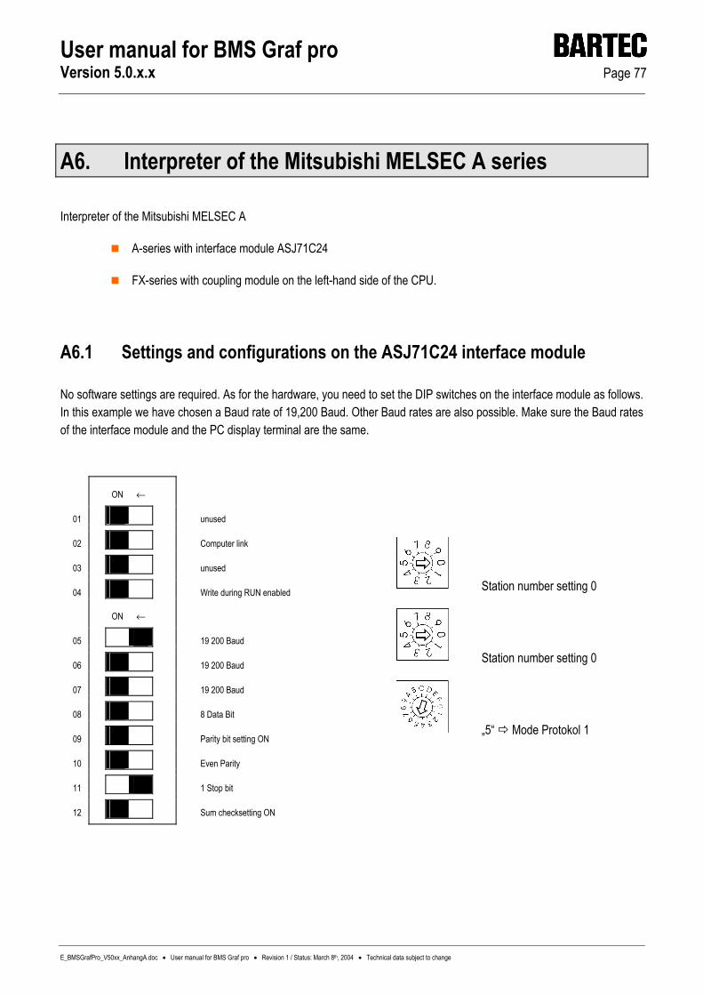
User manual for BMS Graf pro Version 5.0.x.x Page 77
E_BMSGrafPro_V50xx_AnhangA.doc • User manual for BMS Graf pro • Revision 1 / Status: March 8th, 2004 • Technical data subject to change
A6. Interpreter of the Mitsubishi MELSEC A series
Interpreter of the Mitsubishi MELSEC A
A-series with interface module ASJ71C24
FX-series with coupling module on the left-hand side of the CPU.
A6.1 Settings and configurations on the ASJ71C24 interface module
No software settings are required. As for the hardware, you need to set the DIP switches on the interface module as follows. In this example we have chosen a Baud rate of 19,200 Baud. Other Baud rates are also possible. Make sure the Baud rates of the interface module and the PC display terminal are the same.
ON ←
01 unused
02 Computer link
03 unused
04 Write during RUN enabled
ON ←
05 19 200 Baud
06 19 200 Baud
07 19 200 Baud
08 8 Data Bit
09 Parity bit setting ON
10 Even Parity
11 1 Stop bit
12 Sum checksetting ON
Station number setting 0
Station number setting 0
„5“ Mode Protokol 1

User manual for BMS Graf pro Version 5.0.x.x Page 78
E_BMSGrafPro_V50xx_AnhangA.doc • User manual for BMS Graf pro • Revision 1 / Status: March 8th, 2004 • Technical data subject to change
A6.1.1 Connection diagram of the interface module ASJ71C24
BAT 2 / BAT VGA COM1 RS422 ASJ71C24
Make sure you use double-stranded cables only. The connections to the interface module must be given two terminating resistors.
A6.2 COM port settings
Select the port for the control unit and the download.
Select the port for a bar code scanner.
Select the port for a serial printer.

User manual for BMS Graf pro Version 5.0.x.x Page 79
E_BMSGrafPro_V50xx_AnhangA.doc • User manual for BMS Graf pro • Revision 1 / Status: March 8th, 2004 • Technical data subject to change
A6.3 Error messages
Example of an error message display:
A6.3.1 Possible error messages
Message Cause Possible remedy
No communication with control unit SPC connection has failed. Check connection cable: may be unplugged or faulty. Check COM port settings. Check slave number.
No project available The interpreter did not find any project file in the terminal.
Repeat download.
Project faulty The interpreter has found faults in the project file. The last download was faulty.
Repeat download.
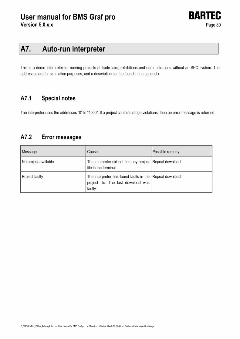
User manual for BMS Graf pro Version 5.0.x.x Page 80
E_BMSGrafPro_V50xx_AnhangA.doc • User manual for BMS Graf pro • Revision 1 / Status: March 8th, 2004 • Technical data subject to change
A7. Auto-run interpreter
This is a demo interpreter for running projects at trade fairs, exhibitions and demonstrations without an SPC system. The addresses are for simulation purposes, and a description can be found in the appendix.
A7.1 Special notes
The interpreter uses the addresses “0” to “4000”. If a project contains range violations, then an error message is returned.
A7.2 Error messages
Message Cause Possible remedy
No project available The interpreter did not find any project file in the terminal.
Repeat download.
Project faulty The interpreter has found faults in the project file. The last download was faulty.
Repeat download.
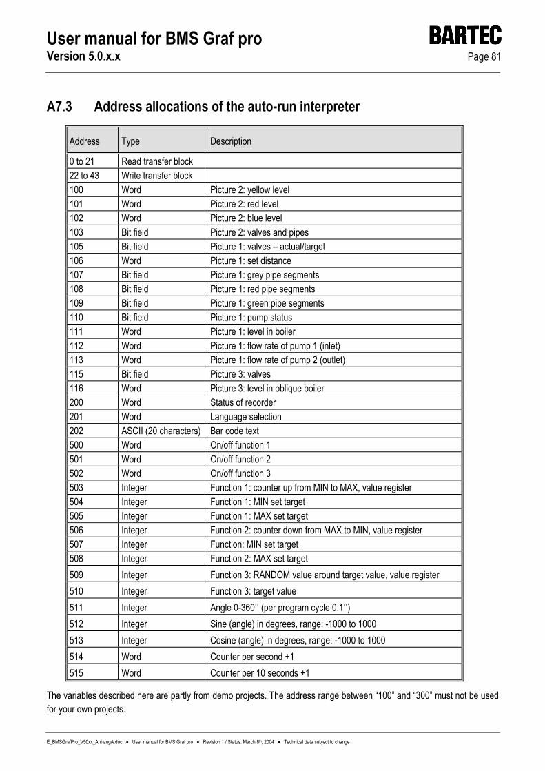
User manual for BMS Graf pro Version 5.0.x.x Page 81
E_BMSGrafPro_V50xx_AnhangA.doc • User manual for BMS Graf pro • Revision 1 / Status: March 8th, 2004 • Technical data subject to change
A7.3 Address allocations of the auto-run interpreter
Address Type Description
0 to 21 Read transfer block 22 to 43 Write transfer block 100 Word Picture 2: yellow level 101 Word Picture 2: red level 102 Word Picture 2: blue level 103 Bit field Picture 2: valves and pipes 105 Bit field Picture 1: valves – actual/target 106 Word Picture 1: set distance 107 Bit field Picture 1: grey pipe segments 108 Bit field Picture 1: red pipe segments 109 Bit field Picture 1: green pipe segments 110 Bit field Picture 1: pump status 111 Word Picture 1: level in boiler 112 Word Picture 1: flow rate of pump 1 (inlet) 113 Word Picture 1: flow rate of pump 2 (outlet) 115 Bit field Picture 3: valves 116 Word Picture 3: level in oblique boiler 200 Word Status of recorder 201 Word Language selection 202 ASCII (20 characters) Bar code text 500 Word On/off function 1 501 Word On/off function 2 502 Word On/off function 3 503 Integer Function 1: counter up from MIN to MAX, value register 504 Integer Function 1: MIN set target 505 Integer Function 1: MAX set target 506 Integer Function 2: counter down from MAX to MIN, value register 507 Integer Function: MIN set target 508 Integer Function 2: MAX set target 509 Integer Function 3: RANDOM value around target value, value register 510 Integer Function 3: target value 511 Integer Angle 0-360° (per program cycle 0.1°) 512 Integer Sine (angle) in degrees, range: -1000 to 1000 513 Integer Cosine (angle) in degrees, range: -1000 to 1000 514 Word Counter per second +1 515 Word Counter per 10 seconds +1
The variables described here are partly from demo projects. The address range between “100” and “300” must not be used for your own projects.
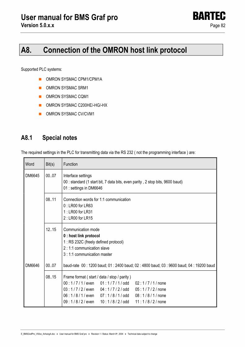
User manual for BMS Graf pro Version 5.0.x.x Page 82
E_BMSGrafPro_V50xx_AnhangA.doc • User manual for BMS Graf pro • Revision 1 / Status: March 8th, 2004 • Technical data subject to change
A8. Connection of the OMRON host link protocol
Supported PLC systems:
OMRON SYSMAC CPM1/CPM1A
OMRON SYSMAC SRM1
OMRON SYSMAC CQM1
OMRON SYSMAC C200HE/-HG/-HX
OMRON SYSMAC CV/CVM1
A8.1 Special notes
The required settings in the PLC for transmitting data via the RS 232 ( not the programming interface ) are:
Word Bit(s) Function
DM6645 00..07 Interface settings 00 : standard (1 start bit, 7 data bits, even parity , 2 stop bits, 9600 baud) 01 : settings in DM6646
08..11 Connection words for 1:1 communication 0 : LR00 for LR63 1 : LR00 for LR31 2 : LR00 for LR15
12..15 Communication mode 0 : host link protocol 1 : RS 232C (freely defined protocol) 2 : 1:1 communication slave 3 : 1:1 communication master
DM6646 00..07 baud-rate 00 : 1200 baud; 01 : 2400 baud; 02 : 4800 baud; 03 : 9600 baud; 04 : 19200 baud
08..15 Frame format ( start / data / stop / parity ) 00 : 1 / 7 / 1 / even 01 : 1 / 7 / 1 / odd 02 : 1 / 7 / 1 / none 03 : 1 / 7 / 2 / even 04 : 1 / 7 / 2 / odd 05 : 1 / 7 / 2 / none 06 : 1 / 8 / 1 / even 07 : 1 / 8 / 1 / odd 08 : 1 / 8 / 1 / none 09 : 1 / 8 / 2 / even 10 : 1 / 8 / 2 / odd 11 : 1 / 8 / 2 / none

User manual for BMS Graf pro Version 5.0.x.x Page 83
E_BMSGrafPro_V50xx_AnhangA.doc • User manual for BMS Graf pro • Revision 1 / Status: March 8th, 2004 • Technical data subject to change
Word Bit(s) function
DM6647 00..15 Transmission delay ( host link protocol ) 0000-9999 ( BCD ): settings in units of 10 ms,
e.g.: a setting of 0001 is equivalent to 10 ms
DM6648 00..07 Node no. ( host link protocol ) also see „PLC station number“ in the interpreter set
up 00 to 31 ( BCD )
08..11 Start code activated (RS-232C) 0 : deactivated 1 : activated
12..15 End code activated (RS-232C) 0 : deactivated ( number of bytes received ) 1 : setting of specific end codes 2 : CR, LF
DM6649 00..07 Start code (RS-232C) 00 to FF (binary)
08..15 bits 12 to 15 of the data word DM6648 are set to 0: number of bytes received 00 : default setting (256 bytes) 01 to FF: 1 to 255 bytes
bits 12 to 15 of the data word DM6648 are set to 1: end code (RS-232C) 01 to FF (binary)
All necessary settings are marked in bold.
Warning:
The pin assignment of the RS232 interface of the PLC does not conform to the standard pin assignment. The PLC or PC terminal can become damaged if connected with an RS232 pin assignment!
Note:
Some addresses ( e.g.: interface settings ) only allow write access by the terminal when the DIL switch ( for CQM1 CPU21 number 1 ) MEMORY PROTECT is set accordingly. Other areas only allow write access when the PLC is operated in a particular mode ( RUN / MONITOR / PROGRAM ).
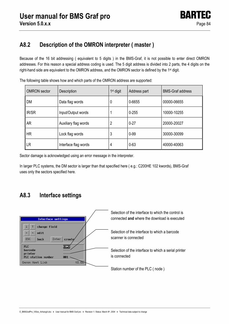
User manual for BMS Graf pro Version 5.0.x.x Page 84
E_BMSGrafPro_V50xx_AnhangA.doc • User manual for BMS Graf pro • Revision 1 / Status: March 8th, 2004 • Technical data subject to change
A8.2 Description of the OMRON interpreter ( master )
Because of the 16 bit addressing ( equivalent to 5 digits ) in the BMS-Graf, it is not possible to enter direct OMRON addresses. For this reason a special address coding is used. The 5 digit address is divided into 2 parts, the 4 digits on the right-hand side are equivalent to the OMRON address, and the OMRON sector is defined by the 1st digit.
The following table shows how and which parts of the OMRON address are supported:
OMRON sector Description 1st digit Address part BMS-Graf address
DM Data flag words 0 0-6655 00000-06655
IR/SR Input/Output words 1 0-255 10000-10255
AR Auxiliary flag words 2 0-27 20000-20027
HR Lock flag words 3 0-99 30000-30099
LR Interface flag words 4 0-63 40000-40063
Sector damage is acknowledged using an error message in the interpreter.
In larger PLC systems, the DM sector is larger than that specified here ( e.g.: C200HE 102 kwords), BMS-Graf uses only the sectors specified here.
A8.3 Interface settings
Selection of the interface to which the control is connected and where the download is executed
Selection of the interface to which a barcode scanner is connected
Selection of the interface to which a serial printer is connected
Station number of the PLC ( node )

User manual for BMS Graf pro Version 5.0.x.x Page 85
E_BMSGrafPro_V50xx_AnhangA.doc • User manual for BMS Graf pro • Revision 1 / Status: March 8th, 2004 • Technical data subject to change
A8.4 Error messages
Example of an error message:
A8.4.1 Possible error messages:
Message Cause Possible rectification
No communication with the control Establishment of connection with the PLC failed
Check connecting cable, it may not be connected or it may be faulty
Check interface parameters
Check node/station number
Are the function codes in the PLC parameterised
No project available The interpreter has found no project file in the terminal.
Repeat download
Project has errors The interpreter has found errors in the project file, the last download has errors
Repeat download

User manual for BMS Graf pro Version 5.0.x.x Page 86
E_BMSGrafPro_V50xx_AnhangA.doc • User manual for BMS Graf pro • Revision 1 / Status: March 8th, 2004 • Technical data subject to change
Message Cause Possible rectification
Access error at address xxxx Omron error code $01 Cannot be executed in the RUN operating mode!
Set PLC to Monitor Mode.
Omron error code $02 Cannot be executed in the MONITOR mode!
Check variables. Check PLC sectors.
Omron error code $0B Cannot be executed in the PROGRAM mode!
Set PLC to Monitor Mode
Omron error code $23 Application memory is write protected!
e.g.: DIP switch 1 of CQM1 is ON. Check variables.
Checksum error indicated by the PLC!
Omron error code $13/$A3 Check interface parameters!
Format error Omron error code $14/$A4 Check interface parameters!
Error on data input to address Omron error code $15/$A5 Check variables
Command is not supported! Omron error code $16 Should never appear, mentioned only for completeness.
Frame length exceeded! Block start : xxxx Block length : xxxx
Omron error code $18/$A8 Data block too large.
Access cannot be executed! Block start : xxxx Block length : xxxx
Omron error code $19
Sector damage! Error discovered in the variable declaration
Check variables
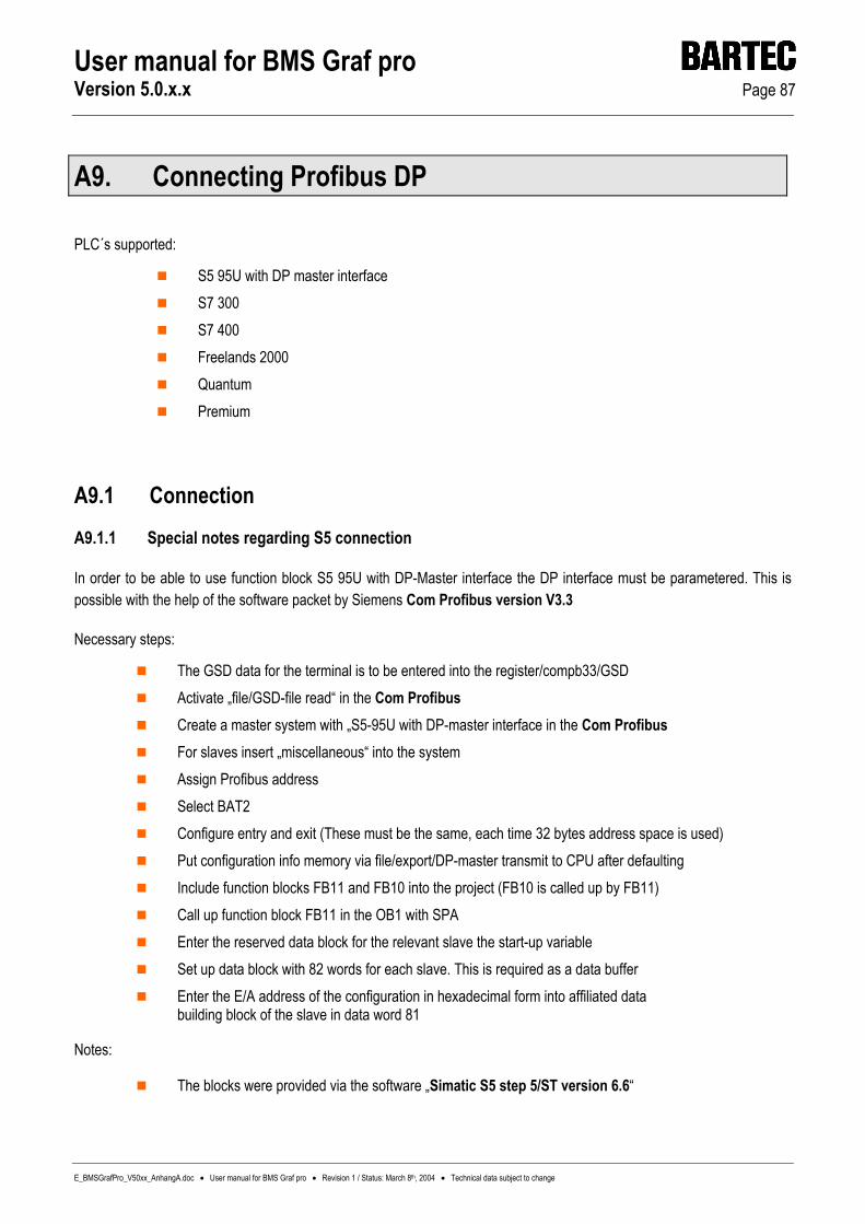
User manual for BMS Graf pro Version 5.0.x.x Page 87
E_BMSGrafPro_V50xx_AnhangA.doc • User manual for BMS Graf pro • Revision 1 / Status: March 8th, 2004 • Technical data subject to change
A9. Connecting Profibus DP
PLC´s supported:
S5 95U with DP master interface S7 300 S7 400 Freelands 2000 Quantum Premium
A9.1 Connection A9.1.1 Special notes regarding S5 connection
In order to be able to use function block S5 95U with DP-Master interface the DP interface must be parametered. This is possible with the help of the software packet by Siemens Com Profibus version V3.3
Necessary steps:
The GSD data for the terminal is to be entered into the register/compb33/GSD Activate „file/GSD-file read“ in the Com Profibus Create a master system with „S5-95U with DP-master interface in the Com Profibus For slaves insert „miscellaneous“ into the system Assign Profibus address Select BAT2 Configure entry and exit (These must be the same, each time 32 bytes address space is used) Put configuration info memory via file/export/DP-master transmit to CPU after defaulting Include function blocks FB11 and FB10 into the project (FB10 is called up by FB11) Call up function block FB11 in the OB1 with SPA Enter the reserved data block for the relevant slave the start-up variable Set up data block with 82 words for each slave. This is required as a data buffer Enter the E/A address of the configuration in hexadecimal form into affiliated data
building block of the slave in data word 81
Notes:
The blocks were provided via the software „Simatic S5 step 5/ST version 6.6“
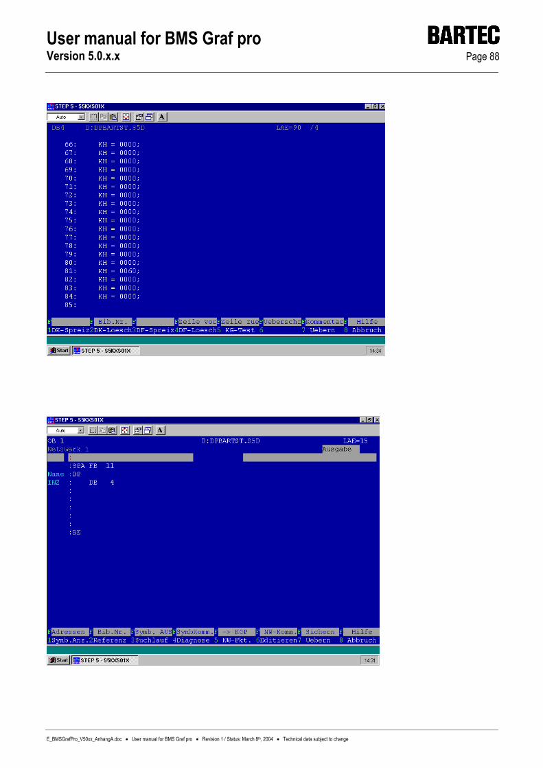
User manual for BMS Graf pro Version 5.0.x.x Page 88
E_BMSGrafPro_V50xx_AnhangA.doc • User manual for BMS Graf pro • Revision 1 / Status: March 8th, 2004 • Technical data subject to change

User manual for BMS Graf pro Version 5.0.x.x Page 89
E_BMSGrafPro_V50xx_AnhangA.doc • User manual for BMS Graf pro • Revision 1 / Status: March 8th, 2004 • Technical data subject to change
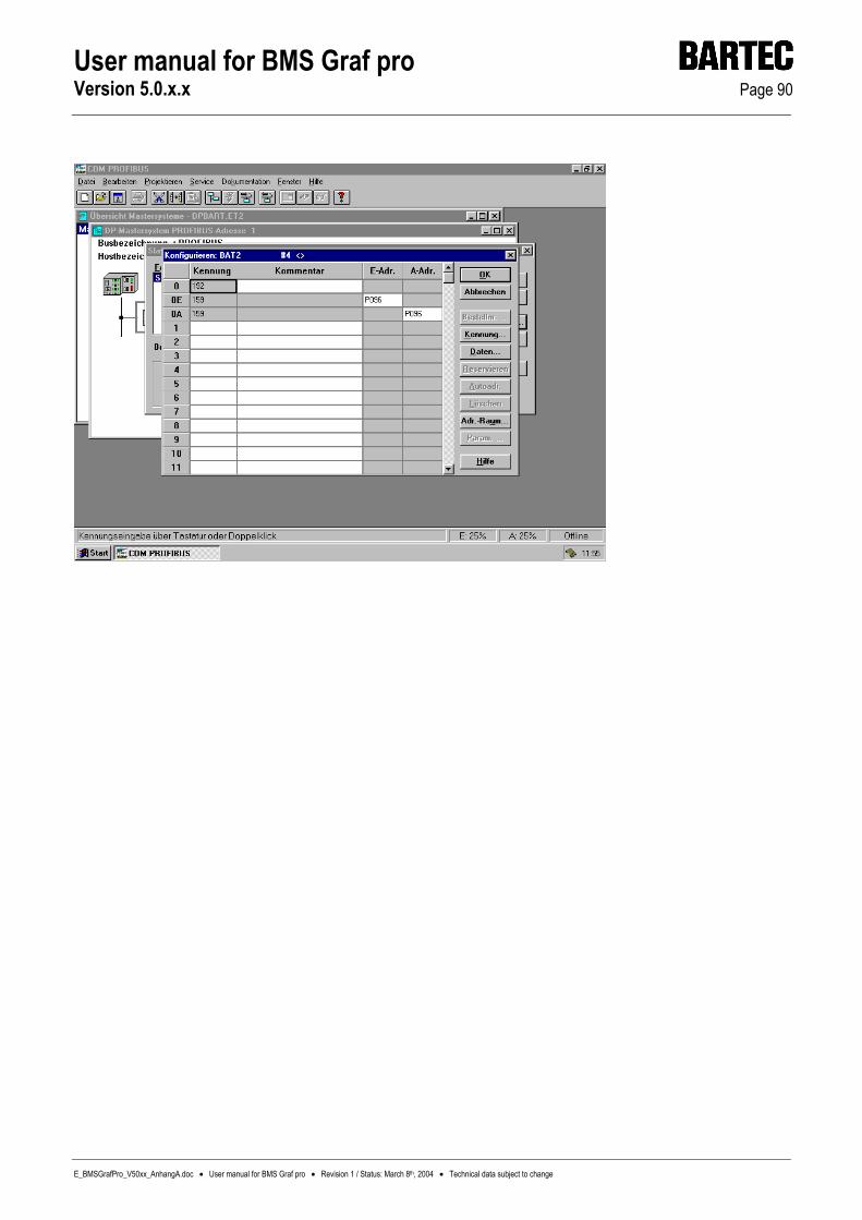
User manual for BMS Graf pro Version 5.0.x.x Page 90
E_BMSGrafPro_V50xx_AnhangA.doc • User manual for BMS Graf pro • Revision 1 / Status: March 8th, 2004 • Technical data subject to change

User manual for BMS Graf pro Version 5.0.x.x Page 91
E_BMSGrafPro_V50xx_AnhangA.doc • User manual for BMS Graf pro • Revision 1 / Status: March 8th, 2004 • Technical data subject to change
A9.1.2 Special notes for S7 connection
For any data transfer between PLC & PC display terminal it is necessary to input into the PLC a function block and to call it up in the PLC operating cycle.
FB10 is a building block for S7 without SFC 24.
This FB can be called up on the terminal with the help of the slave address. The slave address is not the Profibus address. It is the physical address in „Step 7 manager“ of the hardware configuration. Input must be in hexadecimal form (please see example). The entry and exit address must be the same, because one address is transferred when called up.
For FB to function the following is necessary.
Read SFC 14 data from slave in PLC.
Write SFC 15 data for the slave in PLC
The issued function FCI (CRC 16 test sum)
Correct working of the FB10 is ensured only if SFC 14 & SFC 15 are present in the PLC and FCI is loading into the PLC.
The data building blocks for the terminal must be entered and the length must be the same as the length required by the terminal, otherwise the PLC will display an error message. When calling up the FB10, a designated building block must be named. Each terminal requires its own specific DB. The OB 121 prevents the PLC going into STOP mode if DB is missing or wrong. Therefore it is essential that OB 121 is entered within the PLC.
Sample: Call up FB10 Data exchange with terminal
Call up FB10, DB1 Call up FB10 with data instance 1
Slave Address: W#16#0 DP slave projected from address 0
Data exchange with terminal 2
Call FB10, DB2 Call up of FB10 with data instance 2
Slave Address: W#16#20 DP slave projected from address 32.

User manual for BMS Graf pro Version 5.0.x.x Page 92
E_BMSGrafPro_V50xx_AnhangA.doc • User manual for BMS Graf pro • Revision 1 / Status: March 8th, 2004 • Technical data subject to change
A9.1.2.1 GSD - File
GSD-file for BAT 2 / BAT VGA with Profibus from “C:\programs\BARTEC\BMSGrafpro\PLC_PRG\” into Step 7.

User manual for BMS Graf pro Version 5.0.x.x Page 93
E_BMSGrafPro_V50xx_AnhangA.doc • User manual for BMS Graf pro • Revision 1 / Status: March 8th, 2004 • Technical data subject to change
A9.1.2.2 Select terminal as hardware configuration
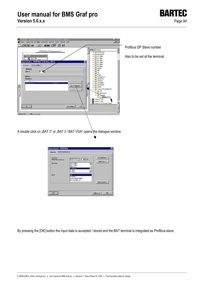
User manual for BMS Graf pro Version 5.0.x.x Page 94
E_BMSGrafPro_V50xx_AnhangA.doc • User manual for BMS Graf pro • Revision 1 / Status: March 8th, 2004 • Technical data subject to change
A double click on „BAT 2“ or „BAT 2 / BAT VGA“ opens the dialogue window.
By pressing the [OK] button the input data is accepted / stored and the BAT terminal is integrated as Profibus-slave.
Profibus DP Slave number
Also to be set at the terminal.

User manual for BMS Graf pro Version 5.0.x.x Page 95
E_BMSGrafPro_V50xx_AnhangA.doc • User manual for BMS Graf pro • Revision 1 / Status: March 8th, 2004 • Technical data subject to change
After double clicking the highlighted row, the following dialogue window can be used for the starting address from the address range of the Profibus. Both addresses (input - output address must be the same !).
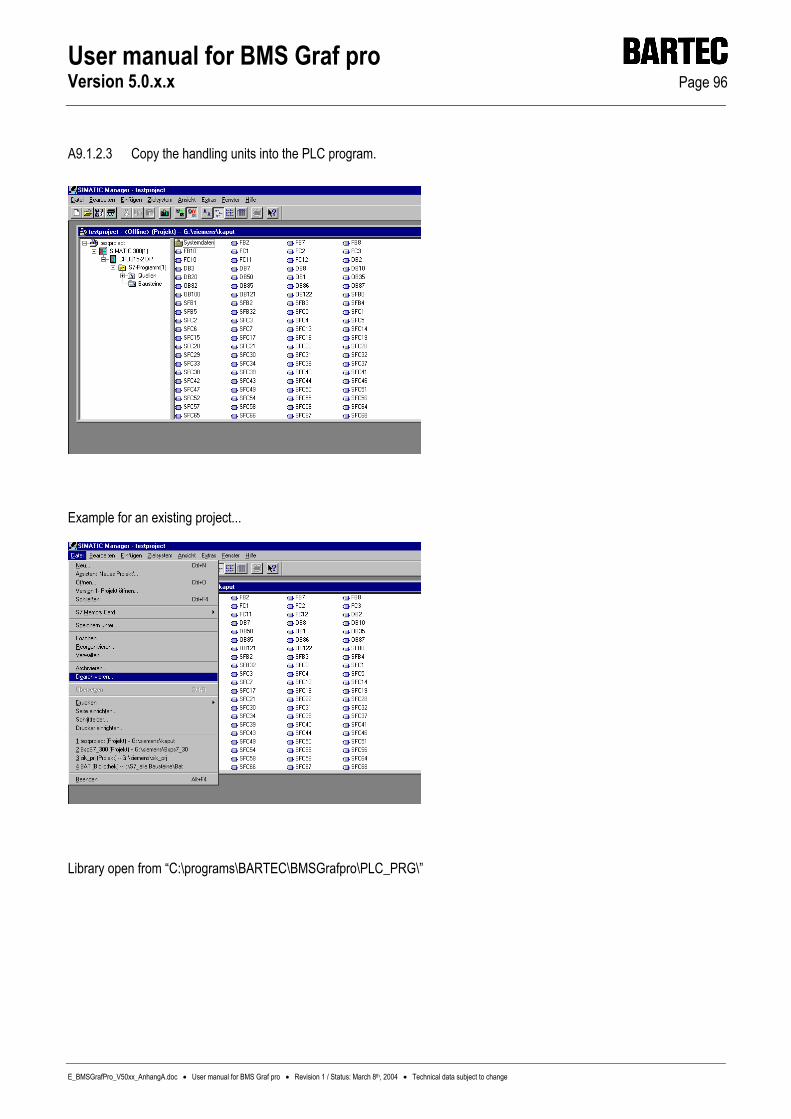
User manual for BMS Graf pro Version 5.0.x.x Page 96
E_BMSGrafPro_V50xx_AnhangA.doc • User manual for BMS Graf pro • Revision 1 / Status: March 8th, 2004 • Technical data subject to change
A9.1.2.3 Copy the handling units into the PLC program.
Example for an existing project...
Library open from “C:\programs\BARTEC\BMSGrafpro\PLC_PRG\”

User manual for BMS Graf pro Version 5.0.x.x Page 97
E_BMSGrafPro_V50xx_AnhangA.doc • User manual for BMS Graf pro • Revision 1 / Status: March 8th, 2004 • Technical data subject to change
After opening the project „BspS7_300“...
... the building units „FB10“ and „FC1“ can be copied into the project.

User manual for BMS Graf pro Version 5.0.x.x Page 98
E_BMSGrafPro_V50xx_AnhangA.doc • User manual for BMS Graf pro • Revision 1 / Status: March 8th, 2004 • Technical data subject to change
A9.1.2.4 Copying into the PLC program (OB1)
Call up the handling unit in OB1, which is described in the appendix A to the handbook BMS-Graf.

User manual for BMS Graf pro Version 5.0.x.x Page 99
E_BMSGrafPro_V50xx_AnhangA.doc • User manual for BMS Graf pro • Revision 1 / Status: March 8th, 2004 • Technical data subject to change
A9.1.3 Special notes for Freelands 2000
see separate documentation
A9.1.4 Quantum
see separate documentation
A9.1.5 Premium
see separate documentation
A9.1.6 Other controls not listed
The necessary handling unit for the particular control can be developed from the following diagram:
A9.1.6.1 Programming of a handling unit for the BAT terminal with PROFIBUS DP interface
The programme in the control system should react to events in the PROFIBUS EA range of the BAT terminal, of size 32 bytes, in the following way. Two commands are defined. If the function code (FC) equals „1“ the terminal transmits data to the control system. If FC equals “2” the terminal requests data from the control system.
Note: The CRC test sum is not required and not used, but is defined in the protocol.
Transmission event:
In the transmission event a response includes only error code and cycle counter.
Set up of data buffer:
Transmission request
Cycle counter FC = 1 Address 1 Address 2 Length Data byte 1 ... Data byte N CRC Low CRC High
Transmission response
Error code Cycle counter CRC Low CRC High

User manual for BMS Graf pro Version 5.0.x.x Page 100
E_BMSGrafPro_V50xx_AnhangA.doc • User manual for BMS Graf pro • Revision 1 / Status: March 8th, 2004 • Technical data subject to change
Fetch event:
In the fetch command a distinction is made between an error-free and faulty request.
In the case of a faulty request the address and length are overwritten with zero. The error code and cycle counter are transferred correctly.
In the case of a faulty request the useful data are attached according to their length.
Set up of the data buffer:
Fetch request
Cycle counter FC = 2 Address 1 Address 2 Length CRC Low CRC High
Fetch response (error-free)
Error code Cycle counter Address 1 Address 2 Length Data byte 1 ... Data byte N CRC Low CRC High
Fetch response (faulty)
Error code Cycle counter Address 1 = 0 Address 2 = 0 Length = 0 CRC Low CRC High
Note: One block stands for one byte.

User manual for BMS Graf pro Version 5.0.x.x Page 101
E_BMSGrafPro_V50xx_AnhangA.doc • User manual for BMS Graf pro • Revision 1 / Status: March 8th, 2004 • Technical data subject to change
Flow chart
Start
Read 32 byte consistent
from slave
Address OK
LengthOK ?
Transfer data to output buffer
Error code = $48
Error code = $49
Error code = $00
Length = 0
Address = 0
Record 32 byte
consistent in slave
Error code = $45
End
yes
yes
yes
No No
No
Cycle
FC=transmit
Address OK
LengthOK ?
FC = Fetch ?
Transfer data to target ragne
Error code = $48
Error code = $49
Error code = $00
yes
yes
yes
No
No No
No
yes
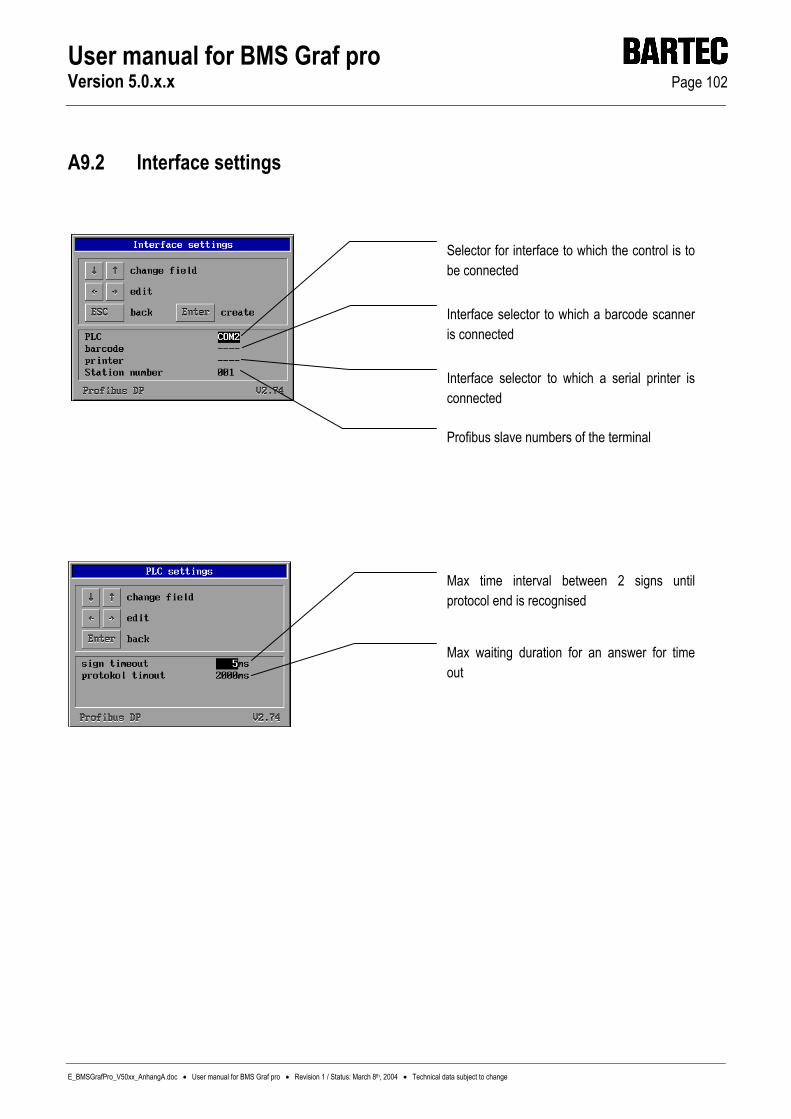
User manual for BMS Graf pro Version 5.0.x.x Page 102
E_BMSGrafPro_V50xx_AnhangA.doc • User manual for BMS Graf pro • Revision 1 / Status: March 8th, 2004 • Technical data subject to change
A9.2 Interface settings
Selector for interface to which the control is to be connected
Interface selector to which a barcode scanner is connected
Interface selector to which a serial printer is connected
Profibus slave numbers of the terminal
Max time interval between 2 signs until protocol end is recognised
Max waiting duration for an answer for time out
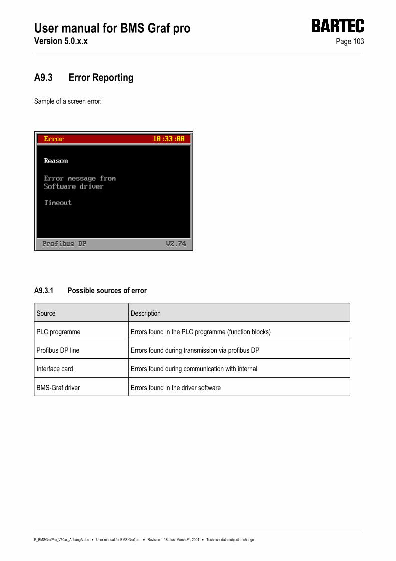
User manual for BMS Graf pro Version 5.0.x.x Page 103
E_BMSGrafPro_V50xx_AnhangA.doc • User manual for BMS Graf pro • Revision 1 / Status: March 8th, 2004 • Technical data subject to change
A9.3 Error Reporting
Sample of a screen error:
A9.3.1 Possible sources of error
Source Description
PLC programme Errors found in the PLC programme (function blocks)
Profibus DP line Errors found during transmission via profibus DP
Interface card Errors found during communication with internal
BMS-Graf driver Errors found in the driver software
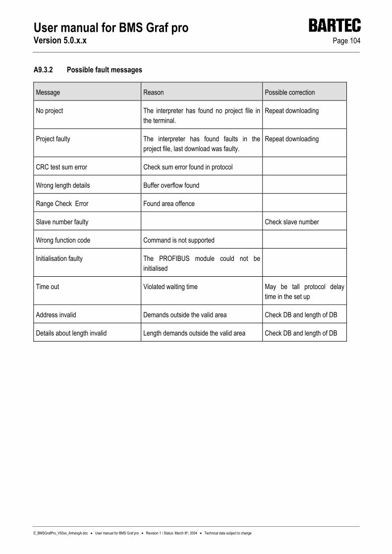
User manual for BMS Graf pro Version 5.0.x.x Page 104
E_BMSGrafPro_V50xx_AnhangA.doc • User manual for BMS Graf pro • Revision 1 / Status: March 8th, 2004 • Technical data subject to change
A9.3.2 Possible fault messages
Message Reason Possible correction
No project The interpreter has found no project file in the terminal.
Repeat downloading
Project faulty The interpreter has found faults in the project file, last download was faulty.
Repeat downloading
CRC test sum error Check sum error found in protocol
Wrong length details Buffer overflow found
Range Check Error Found area offence
Slave number faulty Check slave number
Wrong function code Command is not supported
Initialisation faulty The PROFIBUS module could not be initialised
Time out Violated waiting time May be tall protocol delay time in the set up
Address invalid Demands outside the valid area Check DB and length of DB
Details about length invalid Length demands outside the valid area Check DB and length of DB

User manual for BMS Graf pro Version 5.0.x.x Page 105
E_BMSGrafPro_V50xx_AnhangA.doc • User manual for BMS Graf pro • Revision 1 / Status: March 8th, 2004 • Technical data subject to change
A10. Linking of Interbus S to A250 with BKF102-113
A10.1 Special notes The PLC system supported is A250 with BKF 102 to BKF 113
For the data transfer between the PLC and the PC terminal, it is necessary to load a function block in the PLC and to call it up in the work cycle of the PLC.
A10.1.1 Screenshots of the AKF 8.0 PLC project software
A10.1.1.1 List of equipment for the PLC A250
+------------------------------------------------------------------------------+ ¦+-------------------------------- BES-Editor --------------------------------+¦ ¦¦ SP ¦ Baugruppe ¦ Variante ¦ Z ¦ A ¦ Datentyp ¦ TN-Nr. ¦¦ ¦¦-----+--------------+------------+-----+-----+--------------+---------------¦¦ ¦¦ 0 ¦ ALU 151-1 ¦ ¦ ¦ ¦ ¦ ¦¦ ¦¦ 1 ¦ DNP116 ¦ ¦ ¦ ¦ ¦ 1 ¦¦ ¦¦ 2 ¦ BKF102 ¦ ¦ zyk ¦ ¦ BKFI,BKFS ¦ 1 ¦¦ ¦¦ 3 ¦ ADU116 ¦ ¦ zyk ¦ ¦ EW ¦ 3 ¦¦ ¦¦ 4 ¦ ¦ ¦ ¦ ¦ ¦ ¦¦ ¦¦ 5 ¦______________¦____________¦_____¦_____¦______________¦_______________¦¦ ¦¦ 6 ¦______________¦____________¦_____¦_____¦______________¦_______________¦¦ ¦¦ 7 ¦______________¦____________¦_____¦_____¦______________¦_______________¦¦ ¦¦ 8 ¦______________¦____________¦_____¦_____¦______________¦_______________¦¦ ¦¦ 9 ¦______________¦____________¦_____¦_____¦______________¦_______________¦¦ ¦¦----------------------------------------------------------------------------¦¦ ¦¦ Kommentar: Modnet-1/IS Koppler « SubMag : 20 ¦¦ ¦¦ Baugrtrg.: DTA112 / PAB lokal ¦¦ ¦+----------------------------------------------------------------------------+¦ ¦ _¦ _¦ _¦ _¦ _¦ _¦ _______ _¦ _¦ _¦ _¦ _¦ _¦ ¦ ¦ ____¦ _¦ __¦ _¦ _¦ ____¦ __¦ ____¦ _¦ _¦ ¦ ¦ _¦ _¦ _¦ _¦ _¦ _¦ _¦ _¦ _¦ _¦ _¦ _¦ ¦ ¦ _¦ _¦ _¦ ____¦ ____¦ _¦ _¦ ____¦ ____¦ ____¦ ¦ ¦ ¦ +------------------------------------------------------------------------------+ _¦ BARTEC<OFFLINE>PUTE ¦ ¦ ¦ ¦ ¦
A10.1.1.2 List of equipment for the BKF Unit
+------------------------------------------------------------------------------+ ¦+-------------------------------- BES-Editor --------------------------------+¦ ¦¦ SP ¦ Baugruppe ¦ Variante ¦ G ¦ A ¦ Datentyp ¦ TN-Nr. ¦¦ ¦¦-----+--------------+------------+-----+-----+--------------+---------------¦¦ ¦¦ 20 ¦ AM8 03 ¦ ¦ 000 ¦ 1 ¦ EW,AW ¦ 20 ¦¦ ¦¦ 21 ¦ ¦ ¦ ¦ ¦ ¦ ¦¦ ¦¦ 22 ¦ ¦ ¦ ¦ ¦ ¦ ¦¦ ¦¦ 23 ¦ ¦ ¦ ¦ ¦ ¦ ¦¦ ¦¦ 24 ¦ ¦ ¦ ¦ ¦ ¦ ¦¦ ¦¦ 25 ¦ ¦ ¦ ¦ ¦ ¦ ¦¦ ¦¦ 26 ¦ ¦ ¦ ¦ ¦ ¦ ¦¦ ¦¦ 27 ¦ ¦ ¦ ¦ ¦ ¦ ¦¦ ¦¦ 28 ¦______________¦____________¦_____¦_____¦______________¦_______________¦¦ ¦¦ 29 ¦______________¦____________¦_____¦_____¦______________¦_______________¦¦ ¦¦----------------------------------------------------------------------------¦¦ ¦¦ Kommentar: « ¦¦ ¦¦ Baugrtrg.: DTA-IBS-F / BKF 2 AUTO Bereich: 20- 27 ¦¦ ¦+----------------------------------------------------------------------------+¦ ¦ _¦ _¦ _¦ _¦ _¦ _¦ _______ _¦ _¦ _¦ _¦ _¦ _¦ ¦ ¦ ____¦ _¦ __¦ _¦ _¦ ____¦ __¦ ____¦ _¦ _¦ ¦ ¦ _¦ _¦ _¦ _¦ _¦ _¦ _¦ _¦ _¦ _¦ _¦ _¦ ¦ ¦ _¦ _¦ _¦ ____¦ ____¦ _¦ _¦ ____¦ ____¦ ____¦ ¦ ¦ ¦ +------------------------------------------------------------------------------+ _¦ BARTEC<OFFLINE>PUTE ¦ ¦ ¦ ¦ ¦

User manual for BMS Graf pro Version 5.0.x.x Page 106
E_BMSGrafPro_V50xx_AnhangA.doc • User manual for BMS Graf pro • Revision 1 / Status: March 8th, 2004 • Technical data subject to change
A10.1.1.3 Signal definitions
+------------------------------------------------------------------------------+ ¦+---------------------------- SYM/KOM - Editor ------------------------------+¦ ¦¦Signal Symbol Kommentar » ¦¦ ¦Ã----------------------------------------------------------------------------¦ ¦¦EW20.1 ¦ ¦ ¦¦¦ ¦¦EW20.2 ¦ ¦ ¦¦¦ ¦¦EW20.3 ¦ ¦ ¦¦¦ ¦¦EW20.4 ¦ ¦ ¦¦¦ ¦¦EW20.5 ¦ ¦ ¦¦¦ ¦¦EW20.6 ¦ ¦ ¦¦¦ ¦¦EW20.7 ¦ ¦ ¦¦¦ ¦¦EW20.8 ¦ ¦ ¦¦¦ ¦¦---------Ï------------------------Ï----------------------------------------Ϧ¦ ¦¦AW20.1 ¦ ¦ ¦¦¦ ¦¦AW20.2 ¦ ¦ ¦¦¦ ¦¦AW20.3 ¦ ¦ ¦¦¦ ¦¦AW20.4 ¦ ¦ ¦¦¦ ¦¦AW20.5 ¦ ¦ ¦¦¦ ¦¦AW20.6 ¦ ¦ ¦¦¦ ¦¦AW20.7 ¦ ¦ ¦¦¦ ¦+----------------------------------------------------------------------------+¦ ¦ Darstellungs-Art: SDZ Elementtyp:Wort reine Lesedaten: nein ¦ ¦ <CTRL-ENTER> - Kommandos ¦ +------------------------------------------------------------------------------+ _¦ BARTEC<OFFLINE>PUTE ¦ ¦ ¦ ¦ ¦
A10.1.1.4 Data structure for the link
+------------------------------------------------------------------------------+ ¦+-+------------------------ Datenstruktur-Editor -------------------------+ ¦ ¦¦ ¦ Datenstrukturname: <TRXY > ¦ ¦ ¦¦-¦ ¦ ¦ ¦¦ ¦ Exemplare : 99 ¦ Ext. ladbar: nein ¦ Adressierung : far ¦ ¦ ¦¦ ¦ Elemente, max. : 63 ¦ SYMKOM : ja ¦ Onl.tauschbar: ja ¦ ¦ ¦¦ ¦ davon definiert : 40 ¦ BES-Liste : nein ¦ Initialwerte : ja ¦g ¦ ¦¦ ¦ Größe in Byte : 89 ¦ Extended : nein ¦ komprimierbar: ja ¦ ¦ ¦¦ ¦-----------------------------------------------------------------------¦ ¦ ¦¦ ¦ Lauf-Nr ¦ Anz ¦ Elementtyp ¦ read ¦ write ¦ Sys-wr ¦ DA. ¦ Kommentar ¦__ ¦ ¦¦ ¦ --------+-----+------------+------+-------+--------+-----+---------- ¦__ ¦ ¦¦ ¦ 001-002 ¦ 002 ¦ Adresse ¦ ja ¦ ja ¦ nein ¦ STR ¦ ¦ ¦ ¦¦ ¦ 003-010 ¦ 008 ¦ Wort ¦ ja ¦ ja ¦ nein ¦ BIN ¦ ¦ ¦ ¦+-¦ 011-018 ¦ 008 ¦ Wort ¦ ja ¦ ja ¦ nein ¦ BIN ¦ ¦ ¦ ¦ _¦ 019-026 ¦ 008 ¦ Bit ¦ ja ¦ ja ¦ nein ¦ BIN ¦ ¦ ¦ ¦ _¦ 027-029 ¦ 003 ¦ Byte ¦ ja ¦ ja ¦ nein ¦ DEZ ¦ ¦ ¦ ¦ ¦ 030-032 ¦ 003 ¦ Wort ¦ ja ¦ ja ¦ nein ¦ DEZ ¦ ¦ ¦ ¦ ¦ 033-037 ¦ 005 ¦ Adresse ¦ ja ¦ ja ¦ nein ¦ STR ¦ ¦ ¦ ¦ ¦ 038-040 ¦ 003 ¦ Doppelwort ¦ ja ¦ ja ¦ nein ¦ SDZ ¦ ¦ ¦ ¦ ¦ ¦ ¦ ¦ ¦ ¦ ¦ ¦ ¦ ¦ ¦ ¦ ¦ ¦ ¦ ¦ ¦ ¦ ¦ ¦ ¦ ¦ ¦ ¦ ¦ ¦ ¦ ¦ ¦ ¦ ¦ ¦ ¦ +-----------------------------------------------------------------------+ ¦ +------------------------------------------------------------------------------+ _¦ BARTEC<OFFLINE>PUTE ¦ ¦ ¦ ¦ ¦
A10.1.1.5 Definitions table
¦---------Ï------------------------Ï----------------------Ï----------------Ï- ¦TRXY1 ¦BAT1 ¦ ¦- ¦ ¦TRXY1.1 ¦ ¦ ¦EW20.1 ¦ ¦TRXY1.2 ¦ ¦ ¦AW20.1 ¦ ¦TRXY1.3 ¦ ¦ ¦ ¦ ¦TRXY1.4 ¦ ¦ ¦ ¦ ¦TRXY1.5 ¦ ¦ ¦ ¦ ¦TRXY1.6 ¦ ¦ ¦ ¦ +---------------------------------------------------------------------------- Darstellungs-Art: DEZ Elementtyp:Byte reine Lesedaten: nein <CTRL-ENTER> - Kommandos

User manual for BMS Graf pro Version 5.0.x.x Page 107
E_BMSGrafPro_V50xx_AnhangA.doc • User manual for BMS Graf pro • Revision 1 / Status: March 8th, 2004 • Technical data subject to change
A10.1.1.6 Integration of the function block into the OB1
Baustein Editor :BA FB999 NAME :BATIBS DATE : BAT1 : :L MW1020 :INC := MW1020 :*** Baustein: OB1 Netzwerk: 1 _¦ BARTEC<OFFLINE>PUTE ¦ ¦ ¦ ¦ ¦

User manual for BMS Graf pro Version 5.0.x.x Page 108
E_BMSGrafPro_V50xx_AnhangA.doc • User manual for BMS Graf pro • Revision 1 / Status: March 8th, 2004 • Technical data subject to change
A10.1.2 Short explanation for integrating the function block
The function block FB999 must be called separately for each terminal
Each terminal has to have its own data module of the type „TRXY“.
The input address of the terminal is to be entered with Awx in the first word of the assigned data module.
The output address of the terminal is to be entered with Awx in the second word of the assigned data module.
The terminal data is written to the sector of the flag and read from the same.
Permissible address statements go from 0 to 30000 ( pay attention the upper limit of the PLC )
The following pointers are used in the FB999: P1, P2, P3.

User manual for BMS Graf pro Version 5.0.x.x Page 109
E_BMSGrafPro_V50xx_AnhangA.doc • User manual for BMS Graf pro • Revision 1 / Status: March 8th, 2004 • Technical data subject to change
A10.2 Interface settings
Selection of the interface to which the control is connected.
Selection of the interface to which the barcode scanner is connected.
Selection of the interface to which a serial printer is connected.
Maximum time between two characters until end of protocol is recognised.
Maximum waiting time for a response. For time out.

User manual for BMS Graf pro Version 5.0.x.x Page 110
E_BMSGrafPro_V50xx_AnhangA.doc • User manual for BMS Graf pro • Revision 1 / Status: March 8th, 2004 • Technical data subject to change
A10.3 Error Reporting
Sample of a screen error:
A10.3.1 Possible
Message Reason Possible correction
No project The interpreter has found no project file in the terminal.
Repeat downloading
Project faulty The interpreter has found faults in the project file, last download was faulty.
Repeat downloading
Unknown function code Interpreter error
Wrong CRC16 Part error to bridge
Timeout on Interbus line Timeout for responce Switch PLC into 'Run' mode, check call of function block
Interbus line not aktive Interbus line not aktive Check Interbus, check BKF
Bridge not initialized Interpreter error
Wrong CRC16 by bridge Wrong responce by bridge
Bridge without responce Timeout Change the protocol time out by setup
Break on data stream Need more datas
Details about length invalid Length demands outside the valid area Check DB an length of DB

User manual for BMS Graf pro Version 5.0.x.x Page 111
E_BMSGrafPro_V50xx_AnhangA.doc • User manual for BMS Graf pro • Revision 1 / Status: March 8th, 2004 • Technical data subject to change
A11. Siemens S7 via MPI
A coupling cable, type 17-28TZ-0007, is available for coupling to the MPI bus. This device is an interface converter which converts the MPI protocol into the 3964R/RK512 protocol (physically RS422). For the BAT terminals this means that these require the 3964R driver as protocol driver. Addressing is then carried out to S7 according to the 3964R/RK 512. Caution:
This means that the address of the data word projected in BMS-Graf is doubled in S7. Example:
Address in BMS-Graf Address in S7 DB 30 DW 0 DB 30 DW 0 DB 30 DW 10 DB 30 DW 20 DB 20 DW 100 DB 20 DW 200 Caution:
The address range which is used in the terminal must be present completely in S7, otherwise an error message “communication error” is given in the terminal.
Presettings of the MPI addresses are S7 2 BAT 5 Caution:
This means that only one operating system can be connected to the MPI interface with the MPI cable.
The interface parameters of the terminal must be permanently set to 8 data bits 1 stop bit parity even baud rate19200
The baud rate of the S7 must be set to 187.5 Kbaud.
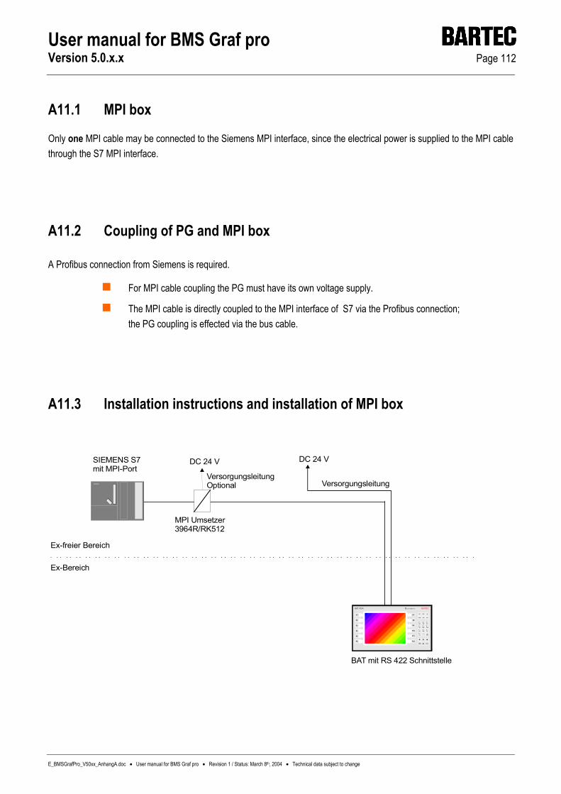
User manual for BMS Graf pro Version 5.0.x.x Page 112
E_BMSGrafPro_V50xx_AnhangA.doc • User manual for BMS Graf pro • Revision 1 / Status: March 8th, 2004 • Technical data subject to change
A11.1 MPI box
Only one MPI cable may be connected to the Siemens MPI interface, since the electrical power is supplied to the MPI cable through the S7 MPI interface.
A11.2 Coupling of PG and MPI box
A Profibus connection from Siemens is required.
For MPI cable coupling the PG must have its own voltage supply.
The MPI cable is directly coupled to the MPI interface of S7 via the Profibus connection; the PG coupling is effected via the bus cable.
A11.3 Installation instructions and installation of MPI box
MPI Umsetzer3964R/RK512
Versorgungsleitung
DC 24 V
Ex-Bereich
SIEMENS S7 mit MPI-Port
Ex-freier Bereich
F7
F8
F9
F10
F11
F12
F1
F2
F3
F4
F5
F6
BAT VGA BARTEC
Ins
Shif t
De l
Al t
i
Ct rl
7 8 9
4 5 6
1 2 3
0 . -
ABC DEF GHI
JKL MNO PQR
STU VWX YZ \
: ( )
Ent erESC
spa ce
EEx me[ib] IIC T4
BAT mit RS 422 Schnittstelle
DC 24 V
VersorgungsleitungOptional

User manual for BMS Graf pro Version 5.0.x.x Page 113
E_BMSGrafPro_V50xx_AnhangA.doc • User manual for BMS Graf pro • Revision 1 / Status: March 8th, 2004 • Technical data subject to change
A11.4 Installation of BAT 2 / BAT VGA to SSW7-RK512/RS422
A11.4.1 Installation to BAT Terminal
For installation you require the following components:
MPI box
Self-made cable adapter between MPI box and BAT terminal
Proceed as follows:
Plug the 9-pole plug of the MPI box to the S7 MPI interface
Connect the 9-pole socket of the MPI box with the self-made cable adapter.
Connect the open conductors of the cable adapter in the BAT terminal.
After downloading the BMS-Graf project, the interface paramters should be set.
A11.5 Cable connection plan – MPI box
S7
ProfibusconnectorSiemens
MPI BOXBAT
Ex-BereichNicht Ex-Bereich

User manual for BMS Graf pro Version 5.0.x.x Page 114
E_BMSGrafPro_V50xx_AnhangA.doc • User manual for BMS Graf pro • Revision 1 / Status: March 8th, 2004 • Technical data subject to change
A11.6 Cable adapter between MPI box and BAT terminal E compartment
Note: This cable adapter is not included in the supply schedule and must be made by the customer.
Pin connections:
SUB-D-plug (to MPI box) 9-pole Terminals in E compartment - BAT
BAT 2 & BAT VGA BAT 300, 800 & VGA pro Enclosure Shield
separate sw 2.5 mm²
Shield
RS422 to COM1 / COM2
to module 422 terminal
1
2
3
4
5
6
7
8
9
Rx A
Rx B
Tx A
Tx B
GND
n.c.
n.c.
n.c.
n.c.
TxD +
TxD -
RxD +
RxD -
1 / 9
2 / 10
3 / 11
4 / 12
1
2
3
4

User manual for BMS Graf pro Version 5.0.x.x Page 115
E_Handbuch_BMSGrafPro_V50xx_AnhangB.doc • User manual for BMS Graf pro • Revision 1 / Status: March 8th, 2004 • Technical data subject to change
Appendix B
User manual for BMS Graf pro Version 5.0.x.x Page 116
E_Handbuch_BMSGrafPro_V50xx_AnhangB.doc • User manual for BMS Graf pro • Revision 1 / Status: March 8th, 2004 • Technical data subject to change
Appendix B – Addition to Runtime version 3.0
B1. Configuration in regular operation................................................................................................... 117
B1.1 Special comments............................................................................................................... 117
B1.2 Error messages................................................................................................................... 117
B2. Menu.................................................................................................................................................... 119
B2.1 Menu point >> Start download <<.................................. 119
B2.2 Menu point >> Password <<.................................. 119
B2.3 Menu point >> Set time/date <<.................................. 120
B2.4 Menu point >> Interface parameters <<.................................. 120
B2.4.1 SPS parameters.................................................................................................................. 120
B2.4.2 Scanner parameters............................................................................................................ 125
B2.4.3 Printer parameters .............................................................................................................. 125
B2.5 Menu point >> History <<................................... 126
B2.6 Menu point >> Set national language <<................................... 126
B2.7 Menu point >> Background lighting <<................................... 127

User manual for BMS Graf pro Version 5.0.x.x Page 117
E_BMSGrafPro_V50xx_AnhangB.doc • User manual for BMS Graf pro • Revision 1 / Status: March 8th, 2004 • Technical data subject to change
B1. Configuration in regular operation
B1.1 Special comments
The special Siemens format „KG“ and other float or real types are not supported in the run time interpreter.
B1.2 Error messages
Error messages are represented in the lower region of the terminal as text lines. The images are also represented for errors in coupling.
The displayed values are NOT updated !
Scrolling in the images using function keys or special keys, previously defined in the project, is possible with delays caused through the protocol.
Owing to standardisation of the error messages from the individual protocol drives, the error messages have changed to version 2.xx. Error messages are always represented as “Source I recognised error”.
Source (signalled from)
General No exact resolution of the source
Run time Errors which do not affect coupling in particular
Driver Communication errors which are recognised in the protocol driver
Control system Check back errors of control system

User manual for BMS Graf pro Version 5.0.x.x Page 118
E_BMSGrafPro_V50xx_AnhangB.doc • User manual for BMS Graf pro • Revision 1 / Status: March 8th, 2004 • Technical data subject to change
Type of error
Error-free Is not displayed
Address information xxx too small Requested address to the SPS is under the permitted range
Address information xxx too large Requested address to the SPS is above the permitted range
Waiting time expired SPS has not responded after the set waiting time
Data buffer overflow More data have arrived than can be processed
No connection to control system SPS has not been found – comparable with waiting time expired
Block length error xx words Requested data range too large
Address information DBxxx too large Requested DB not present or DB request address larger than 255
Address information DWxxx too large
Requested DW in control system not present or DW request address is larger than 255
Error when accessing head data S5-PG: Error when accessing DB head data in the SPS
Error when accessing bookkeeper S5-PG: Error when accessing DB list in the SPS
SPS momentarily occupied SPS indicates that it is occupied – analysis of the SPS time framework is necessary if this message appears frequently
CRC test sum error Test sum error found in the transferred data packet. Reason is often EMC disturbances
Exit value range Exit specified value range
Wrong slave address Slave address not allowed or invalid
Wrong function code Protocol unterfunction not known
Initialisation error Communication module could not be initialised
Wrong address information Address information could not be evaluated
Profibus faulty PROFIBUS-DP not found or faulty or control system (master) is not active.
Project faulty Error found in project data – new download necessary
No project present Project not found – new download necessary

User manual for BMS Graf pro Version 5.0.x.x Page 119
E_BMSGrafPro_V50xx_AnhangB.doc • User manual for BMS Graf pro • Revision 1 / Status: March 8th, 2004 • Technical data subject to change
B2. Menu
Settings during regular operation are achieved by pressing the „i” key. This is similar to the previous set up. If alarms are present these are first displayed. By repeated depression of the „i“ key the set up is reached.
This set up serves the purpose of adapting the interpreter to the respective control system.
B2.1 Menu point >> Start download <<
This menu point serves the purpose of manually starting the download programme of the display terminal.
Following password interrogation the run time interpreter is ended and the main set up started.
Here the menu point „Start download“ must be reselected (the main set up is ended after 5 secs, the run time interpreter restarts)
B2.2 Menu point >> Password <<
All menu points are protected agains unallowed use by a password. The password can be changed here.

User manual for BMS Graf pro Version 5.0.x.x Page 120
E_BMSGrafPro_V50xx_AnhangB.doc • User manual for BMS Graf pro • Revision 1 / Status: March 8th, 2004 • Technical data subject to change
B2.3 Menu point >> Set time/date <<
The system time and system date of the display terminal can be changed here.
Key Effect Reduce value Increase value Select field above Select field below
ESC Truncate process Enter Take over settings
B2.4 Menu point >> Interface parameters <<
B2.4.1 SPS parameters
These settings depend to some extent on the particular interpreter. For example, the interpreter for the S5-PG mode does not provide for any settings for the interface since these settings are fixed by Siemens and cannot be changed. The settings are explained below.
The configuration „wiring side and control side” is explained in appendix A.
Demo run time emulation
The run time emulation is used for starting up projects at exhibitions, trade fairs and demonstrations without SPS system. Addresses for a simulation are specified. These addresses are described in appendix A.
No interface settings are necessary for run time emulation.
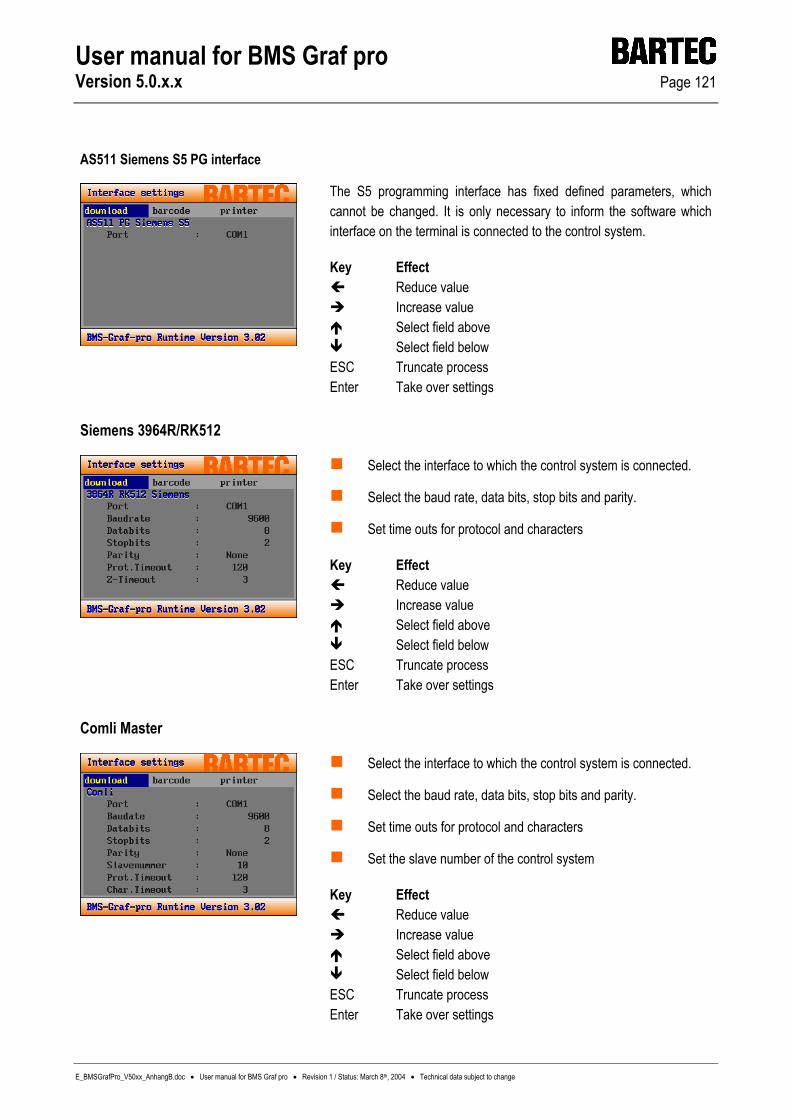
User manual for BMS Graf pro Version 5.0.x.x Page 121
E_BMSGrafPro_V50xx_AnhangB.doc • User manual for BMS Graf pro • Revision 1 / Status: March 8th, 2004 • Technical data subject to change
AS511 Siemens S5 PG interface
The S5 programming interface has fixed defined parameters, which cannot be changed. It is only necessary to inform the software which interface on the terminal is connected to the control system.
Key Effect Reduce value Increase value Select field above Select field below
ESC Truncate process Enter Take over settings
Siemens 3964R/RK512
Select the interface to which the control system is connected.
Select the baud rate, data bits, stop bits and parity.
Set time outs for protocol and characters
Key Effect Reduce value Increase value Select field above Select field below
ESC Truncate process Enter Take over settings
Comli Master
Select the interface to which the control system is connected.
Select the baud rate, data bits, stop bits and parity.
Set time outs for protocol and characters
Set the slave number of the control system
Key Effect Reduce value Increase value Select field above Select field below
ESC Truncate process Enter Take over settings

User manual for BMS Graf pro Version 5.0.x.x Page 122
E_BMSGrafPro_V50xx_AnhangB.doc • User manual for BMS Graf pro • Revision 1 / Status: March 8th, 2004 • Technical data subject to change
Modbus RTU Master [0-65535]
Modbus RTU Master [40001-49999]
Modbus RTU Slave [40001-42000]
Modbus RTU Slave [0-1999]
Select the interface to which the control system is connected.
Select the baud rate, data bits, stop bits and parity.
Set time outs for protocol and characters.
Set the slave number of the control system (master mode)
Set own slave number (slave mode)
Key Effect Reduce value Increase value Select field above Select field below
ESC Truncate process Enter Take over settings

User manual for BMS Graf pro Version 5.0.x.x Page 123
E_BMSGrafPro_V50xx_AnhangB.doc • User manual for BMS Graf pro • Revision 1 / Status: March 8th, 2004 • Technical data subject to change
Mitsubishi Protokoll 1
Mitsubishi Protokoll 1 / Block size 64 words
Host link
Select the interface to which the control system is connected
Select the baud rate, data bits, stop bits and parity.
Set time outs for protocol and characters
Set the slave number of the control system
Key Effect Reduce value Increase value Select field above Select field below
ESC Truncate process Enter Take over settings
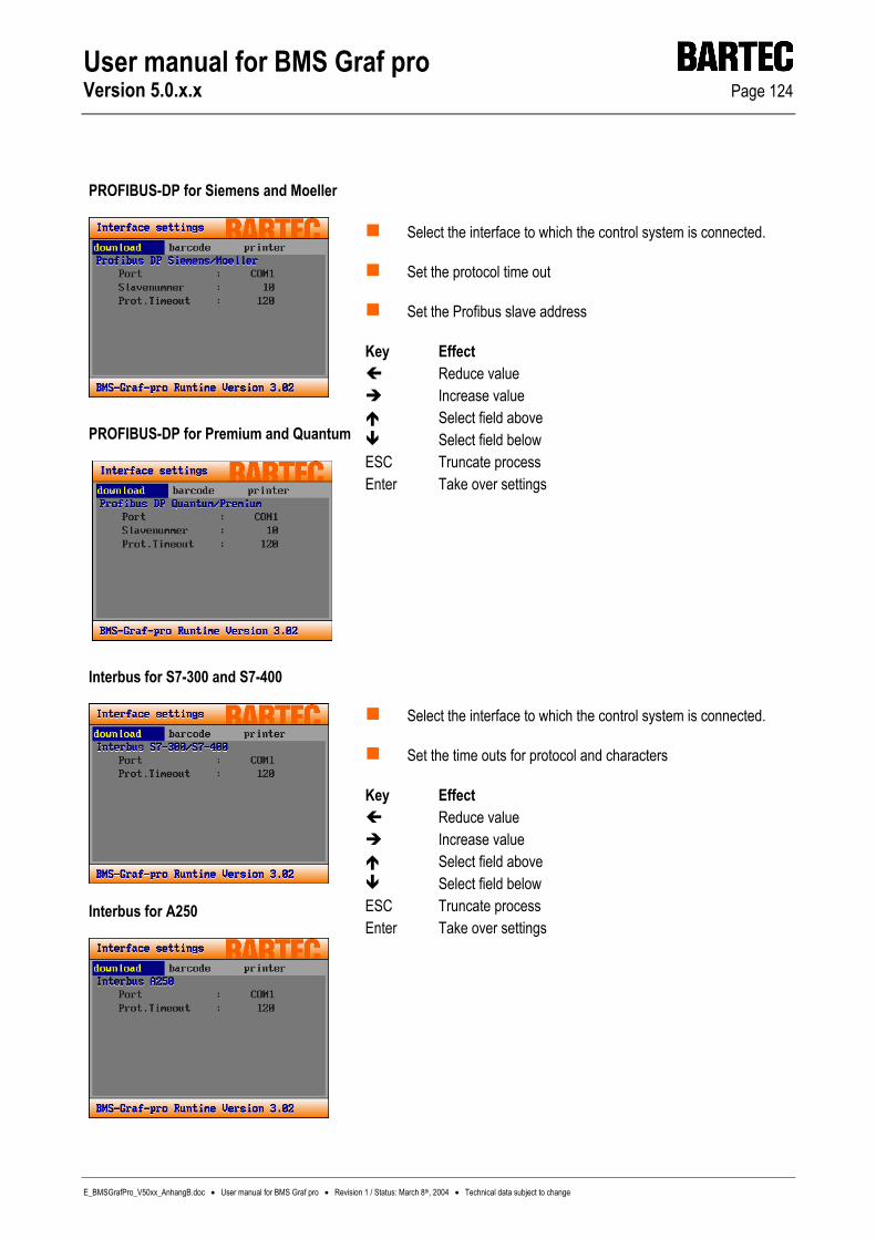
User manual for BMS Graf pro Version 5.0.x.x Page 124
E_BMSGrafPro_V50xx_AnhangB.doc • User manual for BMS Graf pro • Revision 1 / Status: March 8th, 2004 • Technical data subject to change
PROFIBUS-DP for Siemens and Moeller
PROFIBUS-DP for Premium and Quantum
Select the interface to which the control system is connected.
Set the protocol time out
Set the Profibus slave address
Key Effect Reduce value Increase value Select field above Select field below
ESC Truncate process Enter Take over settings
Interbus for S7-300 and S7-400
Interbus for A250
Select the interface to which the control system is connected.
Set the time outs for protocol and characters
Key Effect Reduce value Increase value Select field above Select field below
ESC Truncate process Enter Take over settings
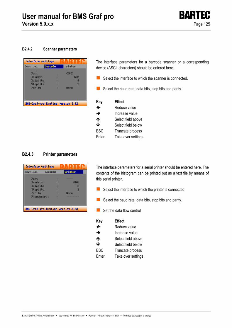
User manual for BMS Graf pro Version 5.0.x.x Page 125
E_BMSGrafPro_V50xx_AnhangB.doc • User manual for BMS Graf pro • Revision 1 / Status: March 8th, 2004 • Technical data subject to change
B2.4.2 Scanner parameters
The interface parameters for a barcode scanner or a corresponding device (ASCII characters) should be entered here.
Select the interface to which the scanner is connected.
Select the baud rate, data bits, stop bits and parity.
Key Effect Reduce value Increase value Select field above Select field below
ESC Truncate process Enter Take over settings
B2.4.3 Printer parameters
The interface parameters for a serial printer should be entered here. The contents of the histogram can be printed out as a text file by means of this serial printer.
Select the interface to which the printer is connected.
Select the baud rate, data bits, stop bits and parity.
Set the data flow control
Key Effect Reduce value Increase value Select field above Select field below
ESC Truncate process Enter Take over settings

User manual for BMS Graf pro Version 5.0.x.x Page 126
E_BMSGrafPro_V50xx_AnhangB.doc • User manual for BMS Graf pro • Revision 1 / Status: March 8th, 2004 • Technical data subject to change
B2.5 Menu point >> History <<
Key Effect Scroll half a page to the left Scroll half a page to the right Scroll half a page upwards Scroll half a page downwards
Del Delete histogram without request Ins Transmit histogram to serial printer ESC Return to menu Enter Return to menu
B2.6 Menu point >> Set national language <<
The national language of the set up can be set here.
Key Effect Scroll half a page upwards Scroll half a page downwards
ESC Return to menu Enter Return to menu

User manual for BMS Graf pro Version 5.0.x.x Page 127
E_BMSGrafPro_V50xx_AnhangB.doc • User manual for BMS Graf pro • Revision 1 / Status: March 8th, 2004 • Technical data subject to change
B2.7 Menu point >> Background lighting <<
This dialogue is used for setting the type of the background lighting (HB)
The switch-off time can be set to 15, 30 and 60 minutes. This setting is effective only if the HG manager is set to time or SPS.
SPS means that the SPS has the possibility of switching off the HB by means of a bit in the transfer block. The time is counted from the last key depression. When the HB is switched off the next key depression activates the HB. This key depression is not transferred to the SPS. While the HB is switched off the red LED at the “i” key flashes.
Key Effect Scroll half a page to the left Scroll half a page to the right Scroll half a page upwards Scroll half a page downwards
Del Delete histogram without request Ins Transmit histogram to serial printer ESC Return to menu Enter Return to menu