e instruction manual - konica minolta · e instruction manual 9224-2887-11 h-a108. 2 thank you for...
TRANSCRIPT

INSTRUCTION MANUALE
9224-2887-11 H-A108

2
Thank you for purchasing the Minolta DiMAGE Scan Multi PRO. The DiMAGE Scan Multi PRO AF-5000 is a Multiple format film scanner capable of scanning 35mm, 120/220 (6x4.5, 6x6, 6x7, 6x8,6x9).This manual has been designed to help you understand the operation of your scanner. Please read thismanual thoroughly to realize all the benefits of your scanner.
The instructions in this manual assume you have a working knowledge of the operating system for yourcomputer (Windows®98, Windows®Me, Windows®2000 Professional, Windows NT® or Macintosh OS) andits conventions. Familiarity with the mouse and standard operating system menus and commands isnecessary before operating the driver software for the DiMAGE Scan Multi PRO.
This manual does not give instruction in the:
• basic use of personal computers.
• use of Windows®98, Windows®2000 Professional, Windows®Me, Windows NT® or Mac OS 8.6 to 9.1.
• use of Adobe Photoshop, Paint Shop Pro, or CorelPhotoPaint.
The examples in this manual use Windows software. The appearance of some screens may differ fromthe examples when using Windows®Me or the Macintosh OS 9.1 operating system.
Microsoft, Windows®, Windows®98, Windows®Me, Windows® 2000 Professional, and Windows NT® areregistered trademarks of the Microsoft Corporation.
Macintosh™, Apple®, and Power Macintosh® are registered trademarks of Apple Computer, Inc.
Adobe® and Photoshop™ are registered trademarks of Adobe Systems Incorporated.
CorelPhotoPaint™ is a trademark of the Corel Corporation.
Paint Shop Pro is the copyright of Met’s Corporation.
Digital ICE3TM, Digital ICETM, Digital ROCTM and Digital GEMTM are trademarks of registeredtrademarks and technolgies of Applied Science Fiction,Inc in U. S. A.Other corporate and product names are the trademarks and registered trademarks of their respectivecompanies.
• Changes or modifications not approved by the party responsible for compliance could void theuser’s authority to operate the equipment.
• This manual may not be copied in part or whole without prior written permission from Minolta Co.,Ltd. ©2001 Minolta Co., Ltd.
• Every necessary caution has been taken to ensure the accuracy of this instruction manual. Pleasecontact us if you have any questions, find any errors, or notice missing information.
• Minolta is not responsible for loss, damage, or other results occurring during the operation of thisproduct.
As an ENERGY STAR Partner, Minolta has determined that this product meets theENERGY STAR guidelines for energy efficiency.
This mark certifies that this product meets the requirements of the EU (European Union)concerning interference causing equipment regulations. CE stands for ConformitéEuropéenne.
This device complies with Part 15 of the FCC Rules. Operation is subjectto the following conditions: (1) This device may not cause harmfulinterference, and (2) this device must accept any interference received,including interference that may cause undesired operation.
To meet FCC regulations, the SCSI cables and IEEE 1394 cables usedwith this scanner must be equipped with ferrite cores.
This Class B digital apparatus complies with Canadian ICES-003.
Cet appareil numérique de la classe B est conforme à la norme NMB-003 du Canada.
Tested by the Minolta Corporation 101 Williams Drive Ramsey, New Jersey 07446 USA
The sound pressure level is less than 70dB according to ISO 3744 or ISO 7779.
Film Scanner:DiMAGE Scan Multi PRO AF-5000

DiMAGE Scan Multi PRO 3
FOR PROPER AND SAFE USE
• Use only within the voltage range specifiedon the unit. Inappropriate current may causedamage or injury through fire or electricshock.
• Do not disassemble this product. Electricshock may cause injury if a high voltagecircuit inside the product is touched. Takethe product to a Minolta Service Facilitywhen repairs are required.
• Immediately unplug the unit and discontinueuse if the product is dropped or subjected toan impact in which the interior is exposed.The continued use of a damaged productmay cause injuries or fire.
• Store this product out of reach of children.Be careful when around children, not toharm them with the product or parts.
• Do not operate this product or handle thepower cord with wet hands. Do not place acontainer with liquid near the product. Ifliquid comes in contact with the product,immediately unplug the unit. The continueduse of a product exposed to a liquid maycause damage or injury through fire orelectric shock.
• Do not insert hands, inflammable objects, ormetal objects such as paper clips or staplesinto this product. It may cause damage orinjury through fire or electric shock.Discontinue use if an object enters theproduct.
• Do not use the product near inflammablegases or liquids such as gasoline, benzine,or paint thinner. Do not use inflammableproducts such as alcohol, benzine, or paintthinner to clean the product. The use ofinflammable cleaners and solvents maycause an explosion or fire.
• Do not damage, twist, modify, heat, or place
Please read and understand each caution before using this product.
• This product should only be operated in thenormal position with the feet on the desktop.Inappropriate placement may result in fire.
• Damage or injury through fire or electricshock may result if the product is used orstored in the following conditions:In humid or dusty environmentsIn direct sunlight or hot environmentsIn smoky or oily areasIn unventilated areasOn unstable or unlevel surfaces
• Insert the plug securely into the electricaloutlet.
• Do not use if the cord is damaged.• Do not connect the ground to a gas pipe,
telephone ground, or water pipe. Impropergrounding can result in injury from electricshock.
• Unplug the product when cleaning or whenthe unit is not in use for long periods.
• Periodically check that the power cord is notdamaged and the plug is clean. Dust anddirt that may collect between the prongs ofthe plugs may result in fire.
WARNING heavy objects on the power cord. Adamaged cord may cause damage or injurythrough fire or electric shock.
• If the product emits a strange odor, heat, orsmoke, discontinue use. Immediately unplugthe power cord taking care not to burnyourself. The continued use of a damagedproduct or part may cause injuries or fire.
• Take the product to a Minolta ServiceFacility when repairs are required.
CAUTION

4
Minolta DiMAGE Scan Multi PRO
35mm film holder (FH-P1), Slide mountholder (SH-P1) and Universal holder (UH-P1)
120/220 (6x4.5, 6x6, 6x7, 6x8, 6x9) filmattachments with glass and glassless
Film Masks
Ultra SCSI D-sub half-pitch 50-pinconnector cable
IEEE1394 connector cable
AC power cord
CD-ROM forDiMAGE ScanMulti PRO softwareand PDF manuals
Warranty card andQuick ReferenceGuide
PACKAGE CONTENTS
THE FOLLOWING CONTENTS SHOULD BE INCLUDED IN THIS PACKAGE
(Shape of plug varies withdestination)
DiMAGE Scan Multi PRO 5
Overview
Scanner Setup
Index Scan
Preview Scan
Appendix
Image Correction
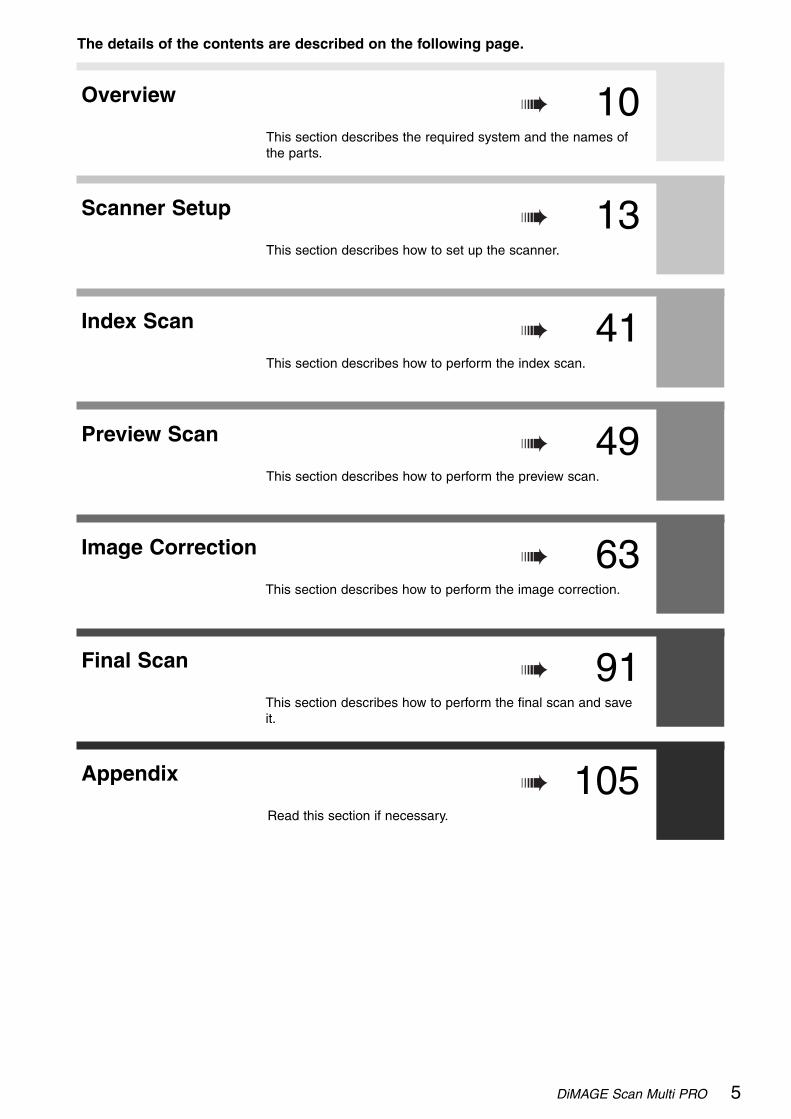
The details of the contents are described on the following page.
This section describes the required system and the names ofthe parts.
This section describes how to set up the scanner.
Final Scan
10
13
This section describes how to perform the index scan.
41
This section describes how to perform the preview scan.
49
This section describes how to perform the final scan and saveit.
63
Read this section if necessary.
91
105
This section describes how to perform the image correction.
6
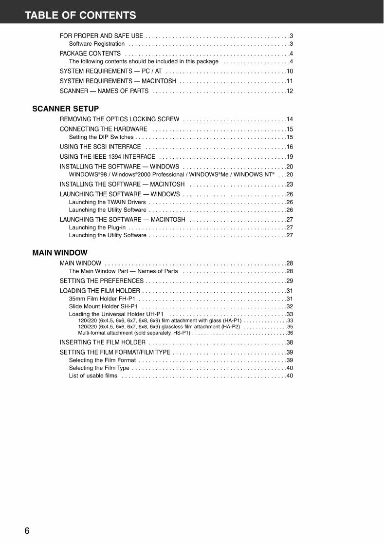
TABLE OF CONTENTS
FOR PROPER AND SAFE USE . . . . . . . . . . . . . . . . . . . . . . . . . . . . . . . . . . . . . . . . . . .3Software Registration . . . . . . . . . . . . . . . . . . . . . . . . . . . . . . . . . . . . . . . . . . . . . . . .3
PACKAGE CONTENTS . . . . . . . . . . . . . . . . . . . . . . . . . . . . . . . . . . . . . . . . . . . . . . . . .4The following contents should be included in this package . . . . . . . . . . . . . . . . . . . .4
SYSTEM REQUIREMENTS — PC / AT . . . . . . . . . . . . . . . . . . . . . . . . . . . . . . . . . . . .10
SYSTEM REQUIREMENTS — MACINTOSH . . . . . . . . . . . . . . . . . . . . . . . . . . . . . . . .11
SCANNER — NAMES OF PARTS . . . . . . . . . . . . . . . . . . . . . . . . . . . . . . . . . . . . . . . .12
SCANNER SETUPREMOVING THE OPTICS LOCKING SCREW . . . . . . . . . . . . . . . . . . . . . . . . . . . . . . .14
CONNECTING THE HARDWARE . . . . . . . . . . . . . . . . . . . . . . . . . . . . . . . . . . . . . . . .15Setting the DIP Switches . . . . . . . . . . . . . . . . . . . . . . . . . . . . . . . . . . . . . . . . . . . . .15
USING THE SCSI INTERFACE . . . . . . . . . . . . . . . . . . . . . . . . . . . . . . . . . . . . . . . . . .16
USING THE IEEE 1394 INTERFACE . . . . . . . . . . . . . . . . . . . . . . . . . . . . . . . . . . . . . .19
INSTALLING THE SOFTWARE — WINDOWS . . . . . . . . . . . . . . . . . . . . . . . . . . . . . . .20WINDOWS®98 / Windows®2000 Professional / WINDOWS®Me / WINDOWS NT® . . .20
INSTALLING THE SOFTWARE — MACINTOSH . . . . . . . . . . . . . . . . . . . . . . . . . . . . .23
LAUNCHING THE SOFTWARE — WINDOWS . . . . . . . . . . . . . . . . . . . . . . . . . . . . . . .26Launching the TWAIN Drivers . . . . . . . . . . . . . . . . . . . . . . . . . . . . . . . . . . . . . . . . .26Launching the Utility Software . . . . . . . . . . . . . . . . . . . . . . . . . . . . . . . . . . . . . . . . .26
LAUNCHING THE SOFTWARE — MACINTOSH . . . . . . . . . . . . . . . . . . . . . . . . . . . . .27Launching the Plug-in . . . . . . . . . . . . . . . . . . . . . . . . . . . . . . . . . . . . . . . . . . . . . . .27Launching the Utility Software . . . . . . . . . . . . . . . . . . . . . . . . . . . . . . . . . . . . . . . . .27
MAIN WINDOWMAIN WINDOW . . . . . . . . . . . . . . . . . . . . . . . . . . . . . . . . . . . . . . . . . . . . . . . . . . . . . .28
The Main Window Part — Names of Parts . . . . . . . . . . . . . . . . . . . . . . . . . . . . . . .28
SETTING THE PREFERENCES . . . . . . . . . . . . . . . . . . . . . . . . . . . . . . . . . . . . . . . . . .29
LOADING THE FILM HOLDER . . . . . . . . . . . . . . . . . . . . . . . . . . . . . . . . . . . . . . . . . . .3135mm Film Holder FH-P1 . . . . . . . . . . . . . . . . . . . . . . . . . . . . . . . . . . . . . . . . . . . .31Slide Mount Holder SH-P1 . . . . . . . . . . . . . . . . . . . . . . . . . . . . . . . . . . . . . . . . . . .32Loading the Universal Holder UH-P1 . . . . . . . . . . . . . . . . . . . . . . . . . . . . . . . . . . .33
120/220 (6x4.5, 6x6, 6x7, 6x8, 6x9) film attachment with glass (HA-P1) . . . . . . . . . . . . . . .33120/220 (6x4.5, 6x6, 6x7, 6x8, 6x9) glassless film attachment (HA-P2) . . . . . . . . . . . . . . .35Multi-format attachment (sold separately, HS-P1) . . . . . . . . . . . . . . . . . . . . . . . . . . . . . . . .36
INSERTING THE FILM HOLDER . . . . . . . . . . . . . . . . . . . . . . . . . . . . . . . . . . . . . . . . .38
SETTING THE FILM FORMAT/FILM TYPE . . . . . . . . . . . . . . . . . . . . . . . . . . . . . . . . . .39Selecting the Film Format . . . . . . . . . . . . . . . . . . . . . . . . . . . . . . . . . . . . . . . . . . . .39Selecting the Film Type . . . . . . . . . . . . . . . . . . . . . . . . . . . . . . . . . . . . . . . . . . . . . .40List of usable films . . . . . . . . . . . . . . . . . . . . . . . . . . . . . . . . . . . . . . . . . . . . . . . . .40

DiMAGE Scan Multi PRO 7
TABLE OF CONTENTS
INDEX SCANINDEX SCAN WINDOW . . . . . . . . . . . . . . . . . . . . . . . . . . . . . . . . . . . . . . . . . . . . . . . .42
The Index Tab Part — Names of Parts . . . . . . . . . . . . . . . . . . . . . . . . . . . . . . . . . .42
MAKING AN INDEX SCAN . . . . . . . . . . . . . . . . . . . . . . . . . . . . . . . . . . . . . . . . . . . . . .43Changing the Window Size . . . . . . . . . . . . . . . . . . . . . . . . . . . . . . . . . . . . . . . . . . .43
SCANNING THE IMAGE . . . . . . . . . . . . . . . . . . . . . . . . . . . . . . . . . . . . . . . . . . . . . . .44Selecting the Frames . . . . . . . . . . . . . . . . . . . . . . . . . . . . . . . . . . . . . . . . . . . . . . .44Rotating or Flipping the Index Frames . . . . . . . . . . . . . . . . . . . . . . . . . . . . . . . . . . .45Reversing the Frame Order . . . . . . . . . . . . . . . . . . . . . . . . . . . . . . . . . . . . . . . . . . .45Full Scale View . . . . . . . . . . . . . . . . . . . . . . . . . . . . . . . . . . . . . . . . . . . . . . . . . . . .45
SAVING THE INDEX SCAN IMAGE . . . . . . . . . . . . . . . . . . . . . . . . . . . . . . . . . . . . . . .46
SAVING THE INDEX IMAGE FILE . . . . . . . . . . . . . . . . . . . . . . . . . . . . . . . . . . . . . . . .47
LOADING THE INDEX IMAGE FILE . . . . . . . . . . . . . . . . . . . . . . . . . . . . . . . . . . . . . . .48
PREVIEW SCANPRESCAN WINDOW . . . . . . . . . . . . . . . . . . . . . . . . . . . . . . . . . . . . . . . . . . . . . . . . . .50
The Prescan Tab Part — Names of Parts . . . . . . . . . . . . . . . . . . . . . . . . . . . . . . . .50
MAKING A PRESCAN . . . . . . . . . . . . . . . . . . . . . . . . . . . . . . . . . . . . . . . . . . . . . . . . .51
ROTATING THE IMAGE . . . . . . . . . . . . . . . . . . . . . . . . . . . . . . . . . . . . . . . . . . . . . . . .52
FLIPPING THE IMAGE . . . . . . . . . . . . . . . . . . . . . . . . . . . . . . . . . . . . . . . . . . . . . . . . .53
FULL SCREEN VIEWING, MAGNIFYING OR REDUCING THE VIEW . . . . . . . . . . . . .54Full Screen View . . . . . . . . . . . . . . . . . . . . . . . . . . . . . . . . . . . . . . . . . . . . . . . . . . .54Magnifying or Reducing the View . . . . . . . . . . . . . . . . . . . . . . . . . . . . . . . . . . . . . .54
SCROLLING THE IMAGE . . . . . . . . . . . . . . . . . . . . . . . . . . . . . . . . . . . . . . . . . . . . . .55
AUTO-EXPOSURE LOCK . . . . . . . . . . . . . . . . . . . . . . . . . . . . . . . . . . . . . . . . . . . . . .56Setting the AE-Lock . . . . . . . . . . . . . . . . . . . . . . . . . . . . . . . . . . . . . . . . . . . . . . . .56Cancelling the AE-Lock . . . . . . . . . . . . . . . . . . . . . . . . . . . . . . . . . . . . . . . . . . . . . .56
AE AREA LOCK . . . . . . . . . . . . . . . . . . . . . . . . . . . . . . . . . . . . . . . . . . . . . . . . . . . . . .57
CROPPING THE IMAGE . . . . . . . . . . . . . . . . . . . . . . . . . . . . . . . . . . . . . . . . . . . . . . .58Auto Cropping . . . . . . . . . . . . . . . . . . . . . . . . . . . . . . . . . . . . . . . . . . . . . . . . . . . . .58Cropping . . . . . . . . . . . . . . . . . . . . . . . . . . . . . . . . . . . . . . . . . . . . . . . . . . . . . . . . .58Cropping the Prescan Image . . . . . . . . . . . . . . . . . . . . . . . . . . . . . . . . . . . . . . . . . .59
FOCUS . . . . . . . . . . . . . . . . . . . . . . . . . . . . . . . . . . . . . . . . . . . . . . . . . . . . . . . . . . . .60Point AF . . . . . . . . . . . . . . . . . . . . . . . . . . . . . . . . . . . . . . . . . . . . . . . . . . . . . . . . .60Manual Focus . . . . . . . . . . . . . . . . . . . . . . . . . . . . . . . . . . . . . . . . . . . . . . . . . . . . .61
DISPLAYING FRAME NUMBER . . . . . . . . . . . . . . . . . . . . . . . . . . . . . . . . . . . . . . . . . .62RGB/CMY Information . . . . . . . . . . . . . . . . . . . . . . . . . . . . . . . . . . . . . . . . . . . . . .62

8
TABLE OF CONTENTS
IMAGE CORRECTIONIMAGE CORRECTION WINDOW . . . . . . . . . . . . . . . . . . . . . . . . . . . . . . . . . . . . . . . . .64
The Image Correction Tab Part — Names of Parts . . . . . . . . . . . . . . . . . . . . . . . . .64
TONE CURVES AND HISTOGRAM . . . . . . . . . . . . . . . . . . . . . . . . . . . . . . . . . . . . . . .65The Tone Curves and Histogram Dialog Box — Names of Parts . . . . . . . . . . . . . . .65Correcting the Tone Curves . . . . . . . . . . . . . . . . . . . . . . . . . . . . . . . . . . . . . . . . . . .66Changing the Tone Curves by Freehand . . . . . . . . . . . . . . . . . . . . . . . . . . . . . . . . .66Setting the White, Black or Grey points . . . . . . . . . . . . . . . . . . . . . . . . . . . . . . . . . .67Viewing the Histogram of Images After Making Corrections . . . . . . . . . . . . . . . . . . .68Auto Setting . . . . . . . . . . . . . . . . . . . . . . . . . . . . . . . . . . . . . . . . . . . . . . . . . . . . . .68Reset . . . . . . . . . . . . . . . . . . . . . . . . . . . . . . . . . . . . . . . . . . . . . . . . . . . . . . . . . . .68Correcting the Histogram . . . . . . . . . . . . . . . . . . . . . . . . . . . . . . . . . . . . . . . . . . . .69
BRIGHTNESS / CONTRAST / COLOUR BALANCE . . . . . . . . . . . . . . . . . . . . . . . . . . .70The Brightness, Contrast and Colour Balance Correction Dialog Box
— Names of Parts . . . . . . . . . . . . . . . . . . . . . . . . . . . . . . . . . . . . . . . . . . . . . . . .70Auto Setting . . . . . . . . . . . . . . . . . . . . . . . . . . . . . . . . . . . . . . . . . . . . . . . . . . . . . .71Reset . . . . . . . . . . . . . . . . . . . . . . . . . . . . . . . . . . . . . . . . . . . . . . . . . . . . . . . . . . .71
HUE / SATURATION / LIGHTNESS . . . . . . . . . . . . . . . . . . . . . . . . . . . . . . . . . . . . . . .72The Hue, Saturation, Lightness Correction Dialog Box — Names of Parts . . . . . . . .72Auto Setting . . . . . . . . . . . . . . . . . . . . . . . . . . . . . . . . . . . . . . . . . . . . . . . . . . . . . .73Reset . . . . . . . . . . . . . . . . . . . . . . . . . . . . . . . . . . . . . . . . . . . . . . . . . . . . . . . . . . .73
VARIATION CORRECTION . . . . . . . . . . . . . . . . . . . . . . . . . . . . . . . . . . . . . . . . . . . . .74The Variation Dialog Box — Names of Parts . . . . . . . . . . . . . . . . . . . . . . . . . . . . . .74Selecting the Correction Item . . . . . . . . . . . . . . . . . . . . . . . . . . . . . . . . . . . . . . . . .74Changing the correction increments . . . . . . . . . . . . . . . . . . . . . . . . . . . . . . . . . . . .74Colour Balance Correction . . . . . . . . . . . . . . . . . . . . . . . . . . . . . . . . . . . . . . . . . . .75Brightness & Contrast Correction . . . . . . . . . . . . . . . . . . . . . . . . . . . . . . . . . . . . . .75Saturation Correction . . . . . . . . . . . . . . . . . . . . . . . . . . . . . . . . . . . . . . . . . . . . . . .76Reset . . . . . . . . . . . . . . . . . . . . . . . . . . . . . . . . . . . . . . . . . . . . . . . . . . . . . . . . . . .76
SELECTIVE COLOUR CORRECTION . . . . . . . . . . . . . . . . . . . . . . . . . . . . . . . . . . . . .77The Selective Colour Correction Dialog Box — Names of Parts . . . . . . . . . . . . . . . .77Reset . . . . . . . . . . . . . . . . . . . . . . . . . . . . . . . . . . . . . . . . . . . . . . . . . . . . . . . . . . .77
UNSHARP MASK . . . . . . . . . . . . . . . . . . . . . . . . . . . . . . . . . . . . . . . . . . . . . . . . . . . .78The Unsharp Mask Dialog Box — Names of Parts . . . . . . . . . . . . . . . . . . . . . . . . .78Reset . . . . . . . . . . . . . . . . . . . . . . . . . . . . . . . . . . . . . . . . . . . . . . . . . . . . . . . . . . .79
SNAPSHOT . . . . . . . . . . . . . . . . . . . . . . . . . . . . . . . . . . . . . . . . . . . . . . . . . . . . . . . . .80Storing in the Snapshot Display Area Temporarily . . . . . . . . . . . . . . . . . . . . . . . . . .80Displaying the Image Stored Temporarily as a Prescan Image . . . . . . . . . . . . . . . . .80
CANCELLING THE IMAGE CORRECTION . . . . . . . . . . . . . . . . . . . . . . . . . . . . . . . . .81Cancelling the Image Correction . . . . . . . . . . . . . . . . . . . . . . . . . . . . . . . . . . . . . . .81Redo the Correction . . . . . . . . . . . . . . . . . . . . . . . . . . . . . . . . . . . . . . . . . . . . . . . .81Delete the Image Correction . . . . . . . . . . . . . . . . . . . . . . . . . . . . . . . . . . . . . . . . . .81
FULL-SCREEN VIEW . . . . . . . . . . . . . . . . . . . . . . . . . . . . . . . . . . . . . . . . . . . . . . . . .82Checking the Correction Result While Lining Up Images . . . . . . . . . . . . . . . . . . . .82
JOB SAVE / JOB LOAD . . . . . . . . . . . . . . . . . . . . . . . . . . . . . . . . . . . . . . . . . . . . . . . .83Saving an Image Correction Job . . . . . . . . . . . . . . . . . . . . . . . . . . . . . . . . . . . . . . .83Loading Image Correction Job . . . . . . . . . . . . . . . . . . . . . . . . . . . . . . . . . . . . . . . .84
DIGITAL ICE / DIGITAL ROC / DIGITAL GEM . . . . . . . . . . . . . . . . . . . . . . . . . . . . . . .85Before Using the Digital ICE/ROC/GEM Function . . . . . . . . . . . . . . . . . . . . . . . . . .85DIGITAL ICE . . . . . . . . . . . . . . . . . . . . . . . . . . . . . . . . . . . . . . . . . . . . . . . . . . . . . .87DIGITAL ROC . . . . . . . . . . . . . . . . . . . . . . . . . . . . . . . . . . . . . . . . . . . . . . . . . . . . .88DIGITAL GEM . . . . . . . . . . . . . . . . . . . . . . . . . . . . . . . . . . . . . . . . . . . . . . . . . . . . .89

DiMAGE Scan Multi PRO 9
FINAL SCANSCAN SETTINGS . . . . . . . . . . . . . . . . . . . . . . . . . . . . . . . . . . . . . . . . . . . . . . . . . . . .92
The Scan Settings Part Window — Names of Parts . . . . . . . . . . . . . . . . . . . . . . . . .92
CREATING / DELETING JOB FILES . . . . . . . . . . . . . . . . . . . . . . . . . . . . . . . . . . . . . .95Creating a Job . . . . . . . . . . . . . . . . . . . . . . . . . . . . . . . . . . . . . . . . . . . . . . . . . . . .95Deleting a Job . . . . . . . . . . . . . . . . . . . . . . . . . . . . . . . . . . . . . . . . . . . . . . . . . . . .95
WHAT IS A JOB? . . . . . . . . . . . . . . . . . . . . . . . . . . . . . . . . . . . . . . . . . . . . . . . . . . . . .96
SCAN JOB TYPE . . . . . . . . . . . . . . . . . . . . . . . . . . . . . . . . . . . . . . . . . . . . . . . . . . . . .97
FINAL SCAN . . . . . . . . . . . . . . . . . . . . . . . . . . . . . . . . . . . . . . . . . . . . . . . . . . . . . . . .98Twain Driver / Plug-in Software . . . . . . . . . . . . . . . . . . . . . . . . . . . . . . . . . . . . . . . .98Utility Software . . . . . . . . . . . . . . . . . . . . . . . . . . . . . . . . . . . . . . . . . . . . . . . . . . . .99
CUSTOM WIZARD . . . . . . . . . . . . . . . . . . . . . . . . . . . . . . . . . . . . . . . . . . . . . . . . . . .100When starting a registered setting . . . . . . . . . . . . . . . . . . . . . . . . . . . . . . . . . . . . .104
APPENDIXIEEE 1394 INTERFACE . . . . . . . . . . . . . . . . . . . . . . . . . . . . . . . . . . . . . . . . . . . . . . .106
COLOUR MATCHING . . . . . . . . . . . . . . . . . . . . . . . . . . . . . . . . . . . . . . . . . . . . . . . .107Output Colour Space Setting . . . . . . . . . . . . . . . . . . . . . . . . . . . . . . . . . . . . . . . . .108ICC Profile Setting . . . . . . . . . . . . . . . . . . . . . . . . . . . . . . . . . . . . . . . . . . . . . . . .108
SCAN JOB FILE LIST — 35 mm . . . . . . . . . . . . . . . . . . . . . . . . . . . . . . . . . . . . . . . .110
SCAN JOB FILE LIST — 120/220 (6X4.5) . . . . . . . . . . . . . . . . . . . . . . . . . . . . . . . . .112
SCAN JOB FILE LIST — 120/220 (6X6) . . . . . . . . . . . . . . . . . . . . . . . . . . . . . . . . . . .114
SCAN JOB FILE LIST — 120/220 (6X7) . . . . . . . . . . . . . . . . . . . . . . . . . . . . . . . . . . .116
SCAN JOB FILE LIST — 120/220 (6X8) . . . . . . . . . . . . . . . . . . . . . . . . . . . . . . . . . . .118
SCAN JOB FILE LIST — 120/220 (6X9) . . . . . . . . . . . . . . . . . . . . . . . . . . . . . . . . . . .120
SCAN JOB FILE LIST — MULTI FORMAT 35 mm . . . . . . . . . . . . . . . . . . . . . . . . . . .122
GLOSSARY . . . . . . . . . . . . . . . . . . . . . . . . . . . . . . . . . . . . . . . . . . . . . . . . . . . . . . . .124
TROUBLE SHOOTING . . . . . . . . . . . . . . . . . . . . . . . . . . . . . . . . . . . . . . . . . . . . . . . .126
USER TECHNICAL SUPPORT . . . . . . . . . . . . . . . . . . . . . . . . . . . . . . . . . . . . . . . . . .127
SPECIFICATIONS . . . . . . . . . . . . . . . . . . . . . . . . . . . . . . . . . . . . . . . . . . . . . . . . . . .128
TABLE OF CONTENTS
10
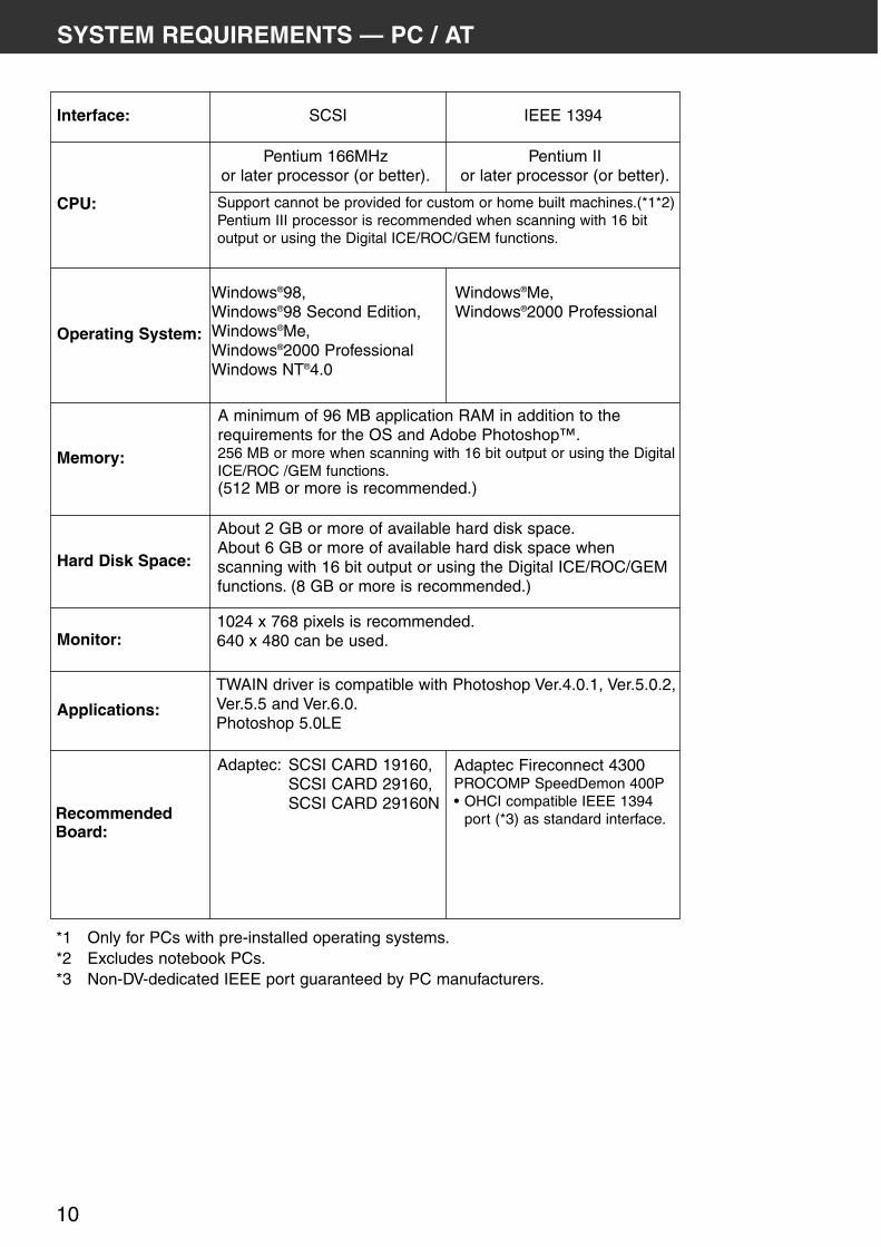
SYSTEM REQUIREMENTS — PC / AT
CPU:
Operating System:
Memory:
Monitor:
Applications:
Pentium 166MHz or later processor (or better).
Windows®Me, Windows®2000 Professional
A minimum of 96 MB application RAM in addition to therequirements for the OS and Adobe Photoshop™.256 MB or more when scanning with 16 bit output or using the DigitalICE/ROC /GEM functions.(512 MB or more is recommended.)
1024 x 768 pixels is recommended.640 x 480 can be used.
TWAIN driver is compatible with Photoshop Ver.4.0.1, Ver.5.0.2,Ver.5.5 and Ver.6.0.Photoshop 5.0LE
Interface:
Hard Disk Space:
About 2 GB or more of available hard disk space.About 6 GB or more of available hard disk space whenscanning with 16 bit output or using the Digital ICE/ROC/GEMfunctions. (8 GB or more is recommended.)
RecommendedBoard:
Adaptec: SCSI CARD 19160, SCSI CARD 29160, SCSI CARD 29160N
Adaptec Fireconnect 4300 PROCOMP SpeedDemon 400P• OHCI compatible IEEE 1394
port (*3) as standard interface.
SCSI IEEE 1394
Support cannot be provided for custom or home built machines.(*1*2)Pentium III processor is recommended when scanning with 16 bitoutput or using the Digital ICE/ROC/GEM functions.
Pentium II or later processor (or better).
Windows®98, Windows®98 Second Edition,Windows®Me, Windows®2000 Professional Windows NT®4.0
*1 Only for PCs with pre-installed operating systems.*2 Excludes notebook PCs.*3 Non-DV-dedicated IEEE port guaranteed by PC manufacturers.

DiMAGE Scan Multi PRO 11
SYSTEM REQUIREMENTS — MACINTOSH
Excludes notebook PCs.Power Macintosh G4 processor is recommended whenscanning with 16 bit output or using the Digital ICE/ROC/GEMfunction.
Mac OS 8.6 to 9.1
A minimum of 64 MB application RAM in addition to therequirements for the Mac OS and Adobe Photoshop™.256 MB or more when loading with 16 bit or using the DigitalICE/ROC/GEM functions.
Plug-in is compatible with Photoshop Ver. 5.02, Ver. 5.5 andVer. 6.0.Photoshop 5.0LE.
About 2GB or more of available hard disk space.About 6 GB or more of available hard disk space when loadingwith 16 bit or using the Digital ICE/ROC/GEM functions. (About8 GB or more is recommended.)
Adaptec:PowerDomain 29160N,PowerDomain 2930U,PowerDomain 2940UW,PowerDomain 2940U2W.
1024 x 768 pixels is recommended.640 x 480 pixels can be used.
Only the standard built-inmodel made by AppleComputer, Inc.
CPU:
Operating System:
Memory:
Monitor:
Applications:
Interface:
Hard Disk Space:
RecommendedBoard:
SCSI FireWire (IEEE 1394)
Power PC 604 or later Power Macintosh G3 or later

12
SCANNER — NAMES OF PARTS
Film-slot door
Indicator lamp
Film Holder Eject button
Power switch
SCSI ID switch
IEEE 1394 interface connector
Dip switches
AC power socket
SCSI Interface connector
DiMAGE Scan Multi PRO 13
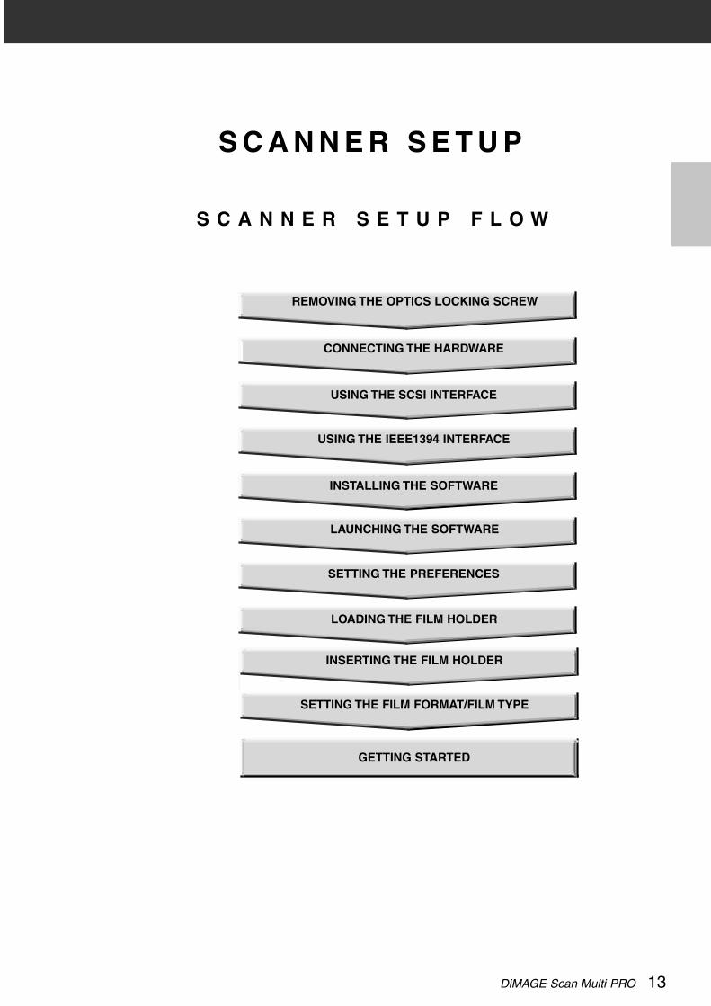
S C A N N E R S E T U P
S C A N N E R S E T U P F L O W
CONNECTING THE HARDWARE
REMOVING THE OPTICS LOCKING SCREW
LAUNCHING THE SOFTWARE
INSTALLING THE SOFTWARE
SETTING THE FILM FORMAT/FILM TYPE
SETTING THE PREFERENCES
INSERTING THE FILM HOLDER
LOADING THE FILM HOLDER
GETTING STARTED
USING THE SCSI INTERFACE
USING THE IEEE1394 INTERFACE

14
REMOVING THE OPTICS LOCKING SCREW
Before using the scanner for the first time, remove the opticslocking screw on the bottom panel of the scanner with a flat-head screwdriver. As the removed locking screw is necessarywhen transporting the scanner, insert it into the storageposistion, for future use.
TRANSPORTING THE SCANNER
When transporting the scanner, move the optics to the lockingposition to prevent damage and then tighten the optics lockingscrew on the bottom panel of the scanner.
1. When the DiMAGE Scan Multi PRO UtilitySoftware is in operation:Windows:Press Ctrl, Shift and L key simultaneously.Macintosh:Press Command , Shift and L keysimultaneously.
2. When “The optics will be moved to thelocked position.” appears on the screen,click on [OK].
3. “The optics have been moved. Turn thescanner off and lock the locking pin.”appears on the screen, click on [OK].• Turn off the power of the scanner and tighten
the optics locking screw.

DiMAGE Scan Multi PRO 15
CONNECTING THE HARDWARE
Switch No. Function ON OFF
1 SCSI terminator ON OFF
2 Auto Power Save ON OFF
3 — — —
4 Select Interface SCSI IEEE 1394
SETTING THE DIP SWITCHES
Before connecting the scanner to a computer turn off the power of the scanner, then, decidewhich interface you will be using, and use the Dip switch No. 4 to set the scanner to the selectedinterface. Set additional Dip switches for termination and auto power save if necessary.
Switch No. 1: SCSI Terminator
Set when selecting SCSI as the interface to be used to connect the scanner to a computer. If thisscanner is the last device of the SCSI chain, set to ON. Switch No. 1 is factory preset to ON.
Switch No. 2: Auto Power Save
Set to “ON” (up), if you want the fluorescent light to turn off automatically, when you are not goingto use it for about 2 hours. In order to save electricity and the life of the fluorescent light, werecommend that you have it “ON”. The default setting is ON.
Switch No. 3: Inactive
Switch No. 4: Selecting an Interface
The selected interface can be switched between SCSI and IEEE 1394 when the scanner isconnected to a computer. The SCSI and IEEE 1394 cannot be used simultaneously. Switch No. 4is factory preset to SCSI.
16
USING THE SCSI INTERFACE
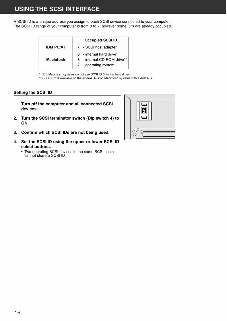
Setting the SCSI ID
1. Turn off the computer and all connected SCSIdevices.
2. Turn the SCSI terminator switch (Dip switch 4) toON.
3. Confirm which SCSI IDs are not being used.
4. Set the SCSI ID using the upper or lower SCSI IDselect buttons.• Two operating SCSI devices in the same SCSI chain
cannot share a SCSI ID.
A SCSI ID is a unique address you assign to each SCSI device connected to your computer.The SCSI ID range of your computer is from 0 to 7, however some ID's are already occupied.
IBM PC/AT
Macintosh
Occupied SCSI ID
7 - SCSI host adapter
0 - internal hard drive*3 - internal CD ROM drive**7 - operating system
* IDE Macintosh systems do not use SCSI ID 0 for the hard drive.** SCSI ID 3 is available on the external bus on Macintosh systems with a dual bus.

DiMAGE Scan Multi PRO 17
USING THE SCSI INTERFACE
4. Turn the SCSI terminatorswitch (Dip switch 1) toOFF.• An external terminator is not
necessary with this scanner.
5. Plug the SCSI cable fromthe next device into theopen port on the back ofthe scanner.
IF THERE ARE OTHER DEVICES IN YOURSCSI CHAIN…
1. Place the scanner on alevel surface.
2. Connect one end of theSCSI cable to either SCSIport on the back of thescanner• Either SCSI port can be
used for other configurations,there is no dedicated in orout port.
3. Connect the other end ofthe SCSI cable to theSCSI port on thecomputer or the lastdevice in the SCSI chain.
Connecting the SCSI Cable
This scanner has been packaged with the SCSI cable SC-P1. See your dealer if you require adifferent SCSI cable.
• To meet FCC regulations, the SCSI cables used with this scanner must be equippedwith ferrite cores.
BEFORE YOU BEGIN…TURN THE COMPUTER AND ALLCONNECTED DEVICES OFF.

18
4. Turn the terminator switch (Dip switch 1) to ON.• An external terminator is not necessary with this
scanner.
5. Plug the power cord into the scanner’s ACsocket, then plug it into a grounded outlet.
IF THE DIMAGE SCAN MULTI PRO IS THE LAST OR ONLYDEVICE IN YOUR SCSI CHAIN…
USING THE SCSI INTERFACE
6. Plug the power cord into the scanner’s ACsocket, then plug it into a grounded outlet.
NOTE:This device is to be used with a powersource within the voltage as specified onthe back of unit.
NOTE:Terminating the SCSI chain helps tosuppress electronic noise in the SCSIchain.Not terminating the SCSI chain can causeslowdowns, data errors, crashes, andother unpredictable errors.
NOTE:This device is to be used with a powersource within the voltage as specified onthe back of unit.
DiMAGE Scan Multi PRO 19
USING THE IEEE 1394 INTERFACE
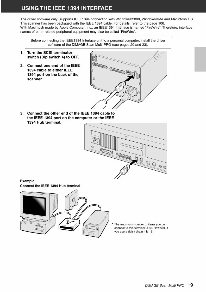
The driver software only supports IEEE1394 connection with Windows®2000, Windows®Me and Macintosh OS.This scanner has been packaged with the IEEE 1394 cable. For details, refer to the page 106.With Macintosh made by Apple Computer, Inc., an IEEE1394 Interface is named “FireWire”. Therefore, interfacenames of other related peripheral equipment may also be called “FireWire”.
Example:Connect the IEEE 1394 Hub terminal
1. Turn the SCSI terminatorswitch (Dip switch 4) to OFF.
2. Connect one end of the IEEE1394 cable to either IEEE1394 port on the back of thescanner.
* The maximum number of items you canconnect to this terminal is 63. However, ifyou use a daisy chain it is 16.
Before connecting the IEEE1394 Interface unit to a personal computer, install the driversoftware of the DiMAGE Scan Multi PRO (see pages 20 and 23).
3. Connect the other end of the IEEE 1394 cable tothe IEEE 1394 port on the computer or the IEEE1394 Hub terminal.

20
WINDOWS®98 / WINDOWS®2000 / WINDOWS®ME / WINDOWS NT®
• In the procedure below, the hard disk drive for system startup is drive C, and the CD-ROM drive is drive D.• Make sure the scanner isn’t connected to the computer when you install the software.
INSTALLING THE SOFTWARE — WINDOWS
1. Turn on the computer to startWindows®.
2. Insert the DiMAGE Scan MultiPRO CD-ROM into the CD-ROM drive.In a little while, a splash screen forSetup will appear.
3. Click on [Starting up theDiMAGE Scan Multi PROinstaller].• In a little while, the program
decompression screen will appearfollowed by the InstallShieldWizard program screen, after thatthe program will startautomatically.
• To confirm the contents of theDiMAGE Scan Multi PRO CD-ROM, click on [To access the CD-ROM].
DiMAGE Scan Multi PRO 21
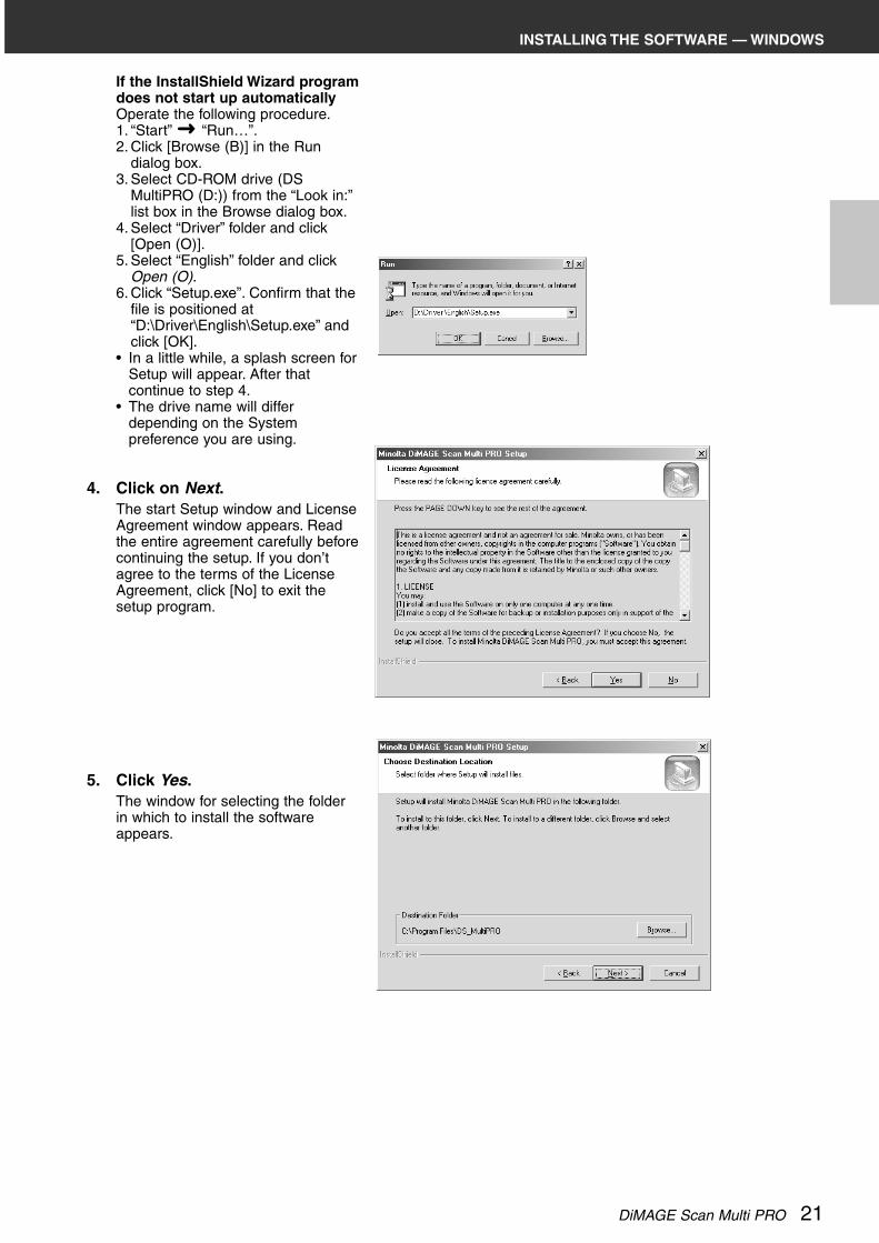
If the InstallShield Wizard programdoes not start up automaticallyOperate the following procedure.1. “Start” “Run…”.2. Click [Browse (B)] in the Run
dialog box.3. Select CD-ROM drive (DS
MultiPRO (D:)) from the “Look in:”list box in the Browse dialog box.
4. Select “Driver” folder and click[Open (O)].
5. Select “English” folder and clickOpen (O).
6. Click “Setup.exe”. Confirm that thefile is positioned at“D:\Driver\English\Setup.exe” andclick [OK].
• In a little while, a splash screen forSetup will appear. After thatcontinue to step 4.
• The drive name will differdepending on the Systempreference you are using.
4. Click on Next.The start Setup window and LicenseAgreement window appears. Readthe entire agreement carefully beforecontinuing the setup. If you don’tagree to the terms of the LicenseAgreement, click [No] to exit thesetup program.
5. Click Yes.The window for selecting the folderin which to install the softwareappears.
INSTALLING THE SOFTWARE — WINDOWS

22
INSTALLING THE SOFTWARE — WINDOWS
6. To install the software in thedefault folder (C:\ProgramFiles\DS_MultiPRO), pressNext.To install the software in anotherfolder, click [Browse...] to display thewindow for selecting a folder. Specifythe directory to install the softwarein, then click [OK].Click [Next>] to display the windowfor selecting the setup type.
7. Select the setup type, thenpress Next.Normally, select “Twain data source”.The rest of the descriptions in thismanual assume the “Twain datasource” setup has been selected.
Click [Next>] to display the windowfor selecting the Program Folder.
8. The name of the defaultProgram Folder is displayed inreverse. To add the softwareicons to this folder, click Next.To add the software icons to anotherexisting folder, select it from thefolderslisted in the box below “ExistingFolders:”, then click [Next>].Installation starts when you click[Next>]. When it has finished, the“InstallShield Wizard Complete”window appears.
9. Check that “Yes, I want torestart my computer now.” isselected, then click Finish.Setup ends, and the computerrestarts.

DiMAGE Scan Multi PRO 23
INSTALLING THE SOFTWARE — MACINTOSH
Please remove or disable any antivirus system extensions before launching thisinstaller. These extensions may conflict with the operation of this installer. Replaceor re-enable them when installation is complete. Hold the shift key down duringstartup to disable the extensions.
1. Turn on the DiMAGE Scan Multi PRO.
2. Turn on the Macintosh and start up theMac OS.
3. Insert the DiMAGE Scan Multi PRO CD-ROM into the CD-ROM drive.• [Dimage Scan Multi PRO] will appear on the
desktop.
4. Double-click on [DiMAGE ScanMulti PRO].• The driver folders will appear.
5. Double-click on [Driver] folder.• The language folders will appear.
6. Open the [English] languagefolder, then double click on [DSMultiPRO Installer].• The installer’s start-up screen will
appear.
7. Click on Continue.• The License screen will appear.

24
INSTALLING THE SOFTWARE — MACINTOSH
Select the installation methodto use.
Name of the volume (disk)and folder in which thesoftware will be installed.
Install type pulldown menu
8. Click on Accept.• If you do not agree to the
conditions stated in the End-UserLicense Agreement, click on[Decline] and the software will notbe installed.
9. Check the folder in which the software will beinstalled. To change it, select “Select folder...”from the “Install Location:” pop- up menu, thenselect an existing folder or create a new one.
10. Select the installation methodfrom the pop- up menu at thetop- left. Normally, you don’tneed to change the installationmethod from “Easy Install”.• If you select “Custom Install”, the
window below appears.Check the check box of the file youwant to install.

DiMAGE Scan Multi PRO 25
11. Click on Install.The following message appearswhen the installer is finished.
12. Click on Quit.• The software will be installed in a
new folder titled DiMAGE ScanMulti PRO.
• If Easy Install was chosen, theDiMAGE Scan Multi PRO folderwill contain the following items:DS_MultiPRO Utility, DS_MultiPROPlug-in, and Read Me file.
13. Drag the DS Multi PRO Plug-into the Import/Export folder inthe Adobe Photoshop Plug-insfolder.• Your Macintosh will restart.
INSTALLING THE SOFTWARE — MACINTOSH

26
LAUNCHING THE UTILITY SOFTWARE
Use the utility software, as a stand alone application, when youjust want to scan the photographic image and store.
1. Select Start Programs Minolta DiMAGE Scan MultiPRO ver.1.0 DS MultiPROUtility.
LAUNCHING THE SOFTWARE — WINDOWS
The TWAIN driver allows you to control the software through another application, such as yourimage editing software.
LAUNCHING THE TWAIN DRIVER
This manual uses Adobe Photoshop Ver.6.0 as the hostapplication. Commands may vary among applications.
1. Open the host application.
2. Select File Import DS_MultiPRO1.0…
For Adobe Photoshop Ver.5 to 5.5(not Ver.6):1.Select File Import
Select TWAIN_32 Source…
2.Select DS_MultiPRO 1.0…, thenclick on [Select].
3.Select File Import TWAIN_32…
The software is ready for use when the Main window appears (page 28).

DiMAGE Scan Multi PRO 27
LAUNCHING THE SOFTWARE — MACINTOSH
The plug-in software lets you access the software through Adobe Photoshop.
LAUNCHING THE PLUG-IN
This manual uses Adobe Photoshop Ver.6.0 as the hostapplication. Commands may vary among applications.
1. Launch Adobe Photoshop.
2. Select File Import DS_MultiPROPlug-in…
The software is ready for use when the Main window appears (page 28).
LAUNCHING THE UTILITY SOFTWARE
Use the utility software, as a stand alone application, when you justwant to scan the photographic image and store.
1. Double click on .

28
MAIN WINDOW — NAMES OF PARTS
MAIN WINDOW
THE MAIN WINDOW PART — NAMES OF PARTS
Tab part• Index (see page 41)• Prescan (see page 49)• ImageCorrection (see page 63)
Scan Setting part (see page 92)
Main Window part (see below)
Holder Type list box
Film format list box
Index Scan button
Prescan button
Scan button
Film Type list box
Preferences button
Close button
Status display area
Custom wizardbutton
Help button (on Macintosh)
Digital GEM button
Digital ROC button
Digital ICE button
Eject button

DiMAGE Scan Multi PRO 29
1. Click on in the Main window.
“Auto Expose for Slides” checkbox
This option allows you to select whether to perform auto exposure during the prescan orthe final scan when using colour slides. As colour slide users often adjust the exposureand colour when taking a photograph, the Auto Expose function when performing theprescan or final scan is turned off in the default setting (The checkmark is not on thecheckbox). However, when scanning a slide which is underexposed or when using the AELock or AE Area lock function (see page 56 to 57), click on the checkbox of “Auto Exposefor Slide” so that the Auto Expose function is turned on.
“Auto Focus at Scan” checkbox
This option allows you to select whether to use the Autofocus function when performingthe prescan or the final scan.To obtain higher scanning speed, the Autofocus function is turned off in the default setting(The checkmark is not on the checkbox). However, if you intend to use the Autofocusfunction when scanning, click on the checkbox of “Auto Focus at Scan”.When using the Digital ICE, ROC or Digital GEM function (see page 85), it isrecommended to turn on the Autofocus function by clicking on the checkbox of “AutoFocus at Scan”.
“Close Driver After Scanning” checkbox
This option allows you to select whether to close the driver software after scanning whenusing Twain driver or Plug-in Software and image editing application.The driver software is specified not to be closed after scanning in the default setting (Thecheckmark is not on the checkbox). This setting is convenient when scanning multipleimages continuously and loading them into an image editing application such as AdobePhotoshop.However, if you intend to retouch each image in the editing software after scanning, clickon the checkbox to display the checkmark.
2. Set the preferences as desired.
ColourMatchingsettings (See page 107)
The Preferences Dialog Box — Name of parts
SETTING THE PREFERENCES

30
3. Click on OK to accept the new preference settings.• Changes to the Preference settings take effect immediately.
SETTING THE PREFERENCES
“Colour depth” setting list box
This option allows you to specify the format when outputting the scanned data to a file or an applicationsoftware. Select one from the following items of the list box.The default setting is 8 bit.• 8 bit Outputs an image of 8 bits for each R, G or B channel• 16 bit Outputs an image of 16 bits for each R, G or B channel• 16 bit linear Outputs an image of 16 bits for each R, G or B channel but corrections such as a gamma
correction cannot be made. Therefore, when scanning a negative film, it is output as anegative image.
* Only TIFF can be selected when using the utility software and selecting 16 bit or 16 bit linear as a colour depth.* When selecting 16 bit, the image size display in the Scan Settings window is represented in the 16 bit size (8 bit x 2).* Some types of graphic application software cannot handle 16 bit image files.
“Multi Sample” scan setting list box
This option allows you to select the Multi-Sampling setting. This function reduces random noise in the imageby analyzing the data of a number of sample scans in advance. Select one of the following items from thelist box.The Multi-Sample Scanning function is turned off in the default setting.• OFF No processing.• 2 times Perform sampling 2 times.• 4 times Perform sampling 4 times.• 8 times Perform sampling 8 times.• 16 times Perform sampling 16 times.* The more times the image is sampled, the longer the required time for scanning.
“Preview Size” selecting list box
Select the display size of the prescan image. The default setting is “Small”.• Large A prescan image is displayed in its original size.• Small A prescan image is displayed in the reduced size.
“Index Scan priority” selection button
This option allows you to select either a high speed index scan or a quality index scan by clicking on“Speed” or “Quality”. The default setting is “Speed”.• Speed This performs the index scan at high speed. The autofocus function is not used while scanning.
The index images are displayed in a thumbnail representation after only easy-auto exposefunction is performed for each frame. When index scanning with a 35 mm film holder (FH-P1), theframe order will differ from that of the actual film frame order. This setting is to allow an evenspeedier index scan. The scanning order is as the numbers marked on the holder 2-1-3-4-6-5.
• Quality After prescanning each frame, the size of the prescan images is reduced and those images aredisplayed in the thumbnail representation. Therefore, it takes longer to display index images.However, the prescan image can then be immediately displayed just by double-clicking the indeximage. Whether the autofocus function or the auto expose function for a colour slide film isperformed when prescanning depends on the setting of Auto Focus at Scan or Auto Exposure forSlides.

DiMAGE Scan Multi PRO 31
35MM FILM HOLDER FH-P1
Use the FH-P1 for 35mm negatives and unmounted 35mmslide film.• The 35mm Film Holder FH-P1 can hold film strips up to 6
frames long.• Blow dust off the film before placing it into the film holder.
1. Position the film holder so thewhite arrow is on the top-left side,then open the slide mount.• Open the slide holder by pulling up
the tab from underneath.
2. Place the film in the filmholder emulsion side down.• Make sure the film strip is under
the two nouches at the top ofthe holder.
3. Align the frames within thescanning windows.
4. Close the cover and pressfirmly until it clicks.
LOADING THE FILM HOLDER
Three types of holder are supplied with this scanner. Select the appropriate one according tothe film type to be scanned.
• 35 mm film holder FH-P1• Slide mount holder SH-P1• Universal holder UH-P1

32
LOADING THE FILM HOLDER
SLIDE MOUNT HOLDER SH-P1
• The slide mount holder SH-P1 can hold up to 4 mountedslides (35mm).
• Slide mounts must be thicker than 1mm and thinner than2mm to fit properly into the holder.
• Blow dust off the slide before placing it into the film holder.
1. Position the slide mount holderSH-P1 so the white arrow is on thetop-left side, then open the slidemount.• Open the slide holder by pushing up
the tab from underneath.
2. Place the slides within theindentations, making sure they lieflat.• Insert the slides emulsion side down.
3. Press the cover firmly closed untilit clicks.
• With the fourth frame of the slide mountholder, you can change slides withoutremoving the slide mount holder from thescanner. A prescan should be made witheach new slide when using the AF and AEfunction (page 29).
NOTE:• Do not scan glass mounted slides. Glass
mounts bend the light from the linescanner, causing bad results.
DiMAGE Scan Multi PRO 33
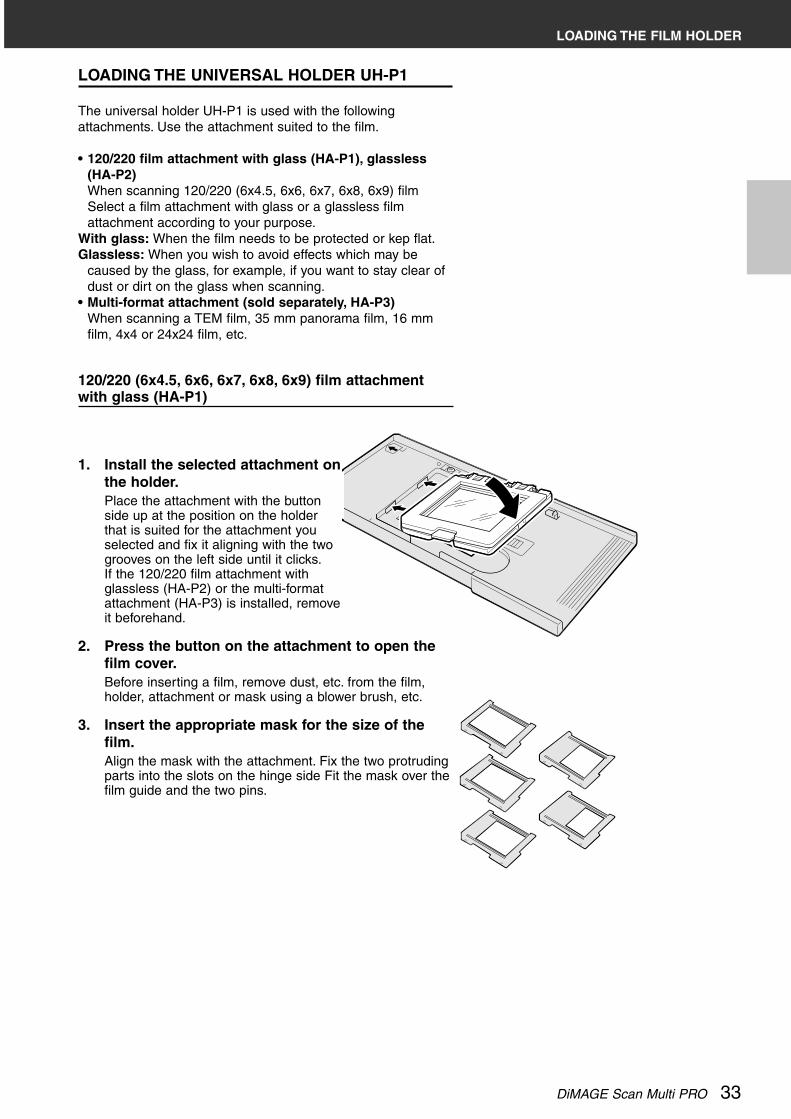
120/220 (6x4.5, 6x6, 6x7, 6x8, 6x9) film attachmentwith glass (HA-P1)
1. Install the selected attachment onthe holder.Place the attachment with the buttonside up at the position on the holderthat is suited for the attachment youselected and fix it aligning with the twogrooves on the left side until it clicks.If the 120/220 film attachment withglassless (HA-P2) or the multi-formatattachment (HA-P3) is installed, removeit beforehand.
2. Press the button on the attachment to open thefilm cover.Before inserting a film, remove dust, etc. from the film,holder, attachment or mask using a blower brush, etc.
3. Insert the appropriate mask for the size of thefilm.Align the mask with the attachment. Fix the two protrudingparts into the slots on the hinge side Fit the mask over thefilm guide and the two pins.
LOADING THE UNIVERSAL HOLDER UH-P1
The universal holder UH-P1 is used with the followingattachments. Use the attachment suited to the film.
• 120/220 film attachment with glass (HA-P1), glassless(HA-P2)When scanning 120/220 (6x4.5, 6x6, 6x7, 6x8, 6x9) filmSelect a film attachment with glass or a glassless filmattachment according to your purpose.
With glass: When the film needs to be protected or kep flat.Glassless: When you wish to avoid effects which may be
caused by the glass, for example, if you want to stay clear ofdust or dirt on the glass when scanning.
• Multi-format attachment (sold separately, HA-P3)When scanning a TEM film, 35 mm panorama film, 16 mmfilm, 4x4 or 24x24 film, etc.
LOADING THE FILM HOLDER

34
Removing a Film
While pressing the button on the lower side of the attachment,lift the film cover.
Removing an Attachment
While sliding the lever on the middle part of the holder to theright, lift the attachment.
4. Place a film on the mask with theemulsion side down while aligningthe lower side of the film with thefilm guide (at the upper or lowerside).
5. Close the film cover of the holderuntil it clicks.
LOADING THE FILM HOLDER
NOTE:• Be sure to fit the appropriate mask
before inserting the film in the scanner.Otherwise, interference fringes with theconcentric circles-patterns may appearon the image after the scanning isperformed.
DiMAGE Scan Multi PRO 35
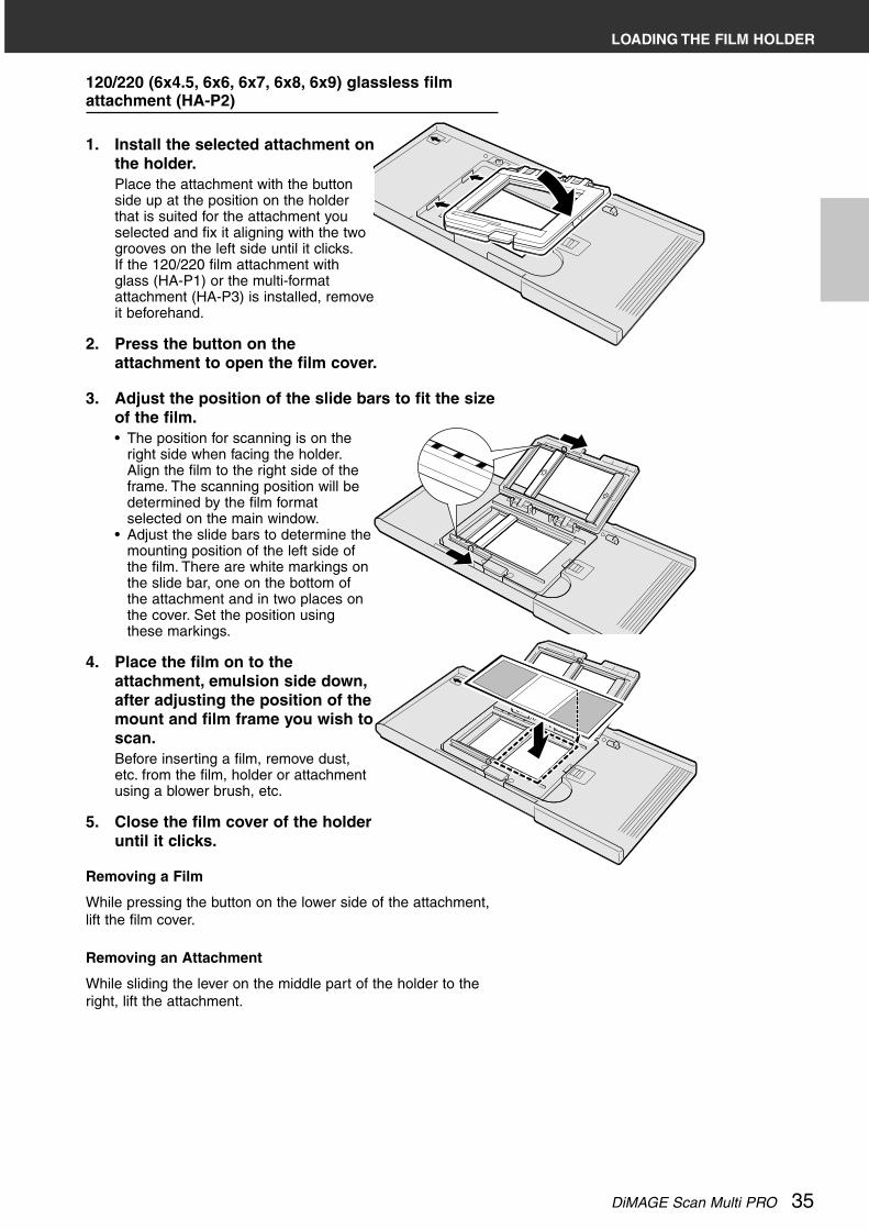
120/220 (6x4.5, 6x6, 6x7, 6x8, 6x9) glassless filmattachment (HA-P2)
1. Install the selected attachment onthe holder.Place the attachment with the buttonside up at the position on the holderthat is suited for the attachment youselected and fix it aligning with the twogrooves on the left side until it clicks.If the 120/220 film attachment withglass (HA-P1) or the multi-formatattachment (HA-P3) is installed, removeit beforehand.
2. Press the button on theattachment to open the film cover.
3. Adjust the position of the slide bars to fit the sizeof the film.• The position for scanning is on the
right side when facing the holder.Align the film to the right side of theframe. The scanning position will bedetermined by the film formatselected on the main window.
• Adjust the slide bars to determine themounting position of the left side ofthe film. There are white markings onthe slide bar, one on the bottom ofthe attachment and in two places onthe cover. Set the position usingthese markings.
4. Place the film on to theattachment, emulsion side down,after adjusting the position of themount and film frame you wish toscan.Before inserting a film, remove dust,etc. from the film, holder or attachmentusing a blower brush, etc.
5. Close the film cover of the holderuntil it clicks.
Removing a Film
While pressing the button on the lower side of the attachment,lift the film cover.
Removing an Attachment
While sliding the lever on the middle part of the holder to theright, lift the attachment.
LOADING THE FILM HOLDER

Multi-format attachment (sold separately, HA-P3)
Purchasing the Multi-format attachment,sold separately, will enable you to deal witha wider range of films such as a 16mm film.Multi-format attachment (HS-P1)The following contents should be included inthis package. If there is an article of inferiorquality or parts missing, please contact the sales agent.
Multi-format attachment (cover part)Multi-format attachment (bottom)3 film masks
1. Place the attachment at the positionon the holder that is suited for theattachment you selected and fix itwhile aligning with the two grooveson the left side until it clicks.If the 120/220 film attachment with glass(HA-P1) or glassless (HA-P2) is installed,remove it beforehand.
2. Fit the two pins on the upper side ofthe film cover into the holes on theupper side of the holder until theyclick.
36
3. Make appropriate mask for the size of the film.When making a mask, cut out the sheet with a cutter, etc.using the scales drawn on the mask as a guide to a sizenot larger or wider than the actual film. If you use a largeror wider mask when scanning, the auto exposure functionmay not be performed.
4. Insert the mask you have cut out.Fix the mask with the scale side facingup inti the slot on the lower side of theholder and then fit the holes on to thetwo pins on the upper side of theholder.Before inserting a film, remove dust,etc. from the film, holder, attachment ormask using a blower brush, etc.
LOADING THE FILM HOLDER

DiMAGE Scan Multi PRO 37
LOADING THE FILM HOLDER
Removing a Film
While sliding the button on the cover of theattachment, lift the film cover.
Removing an Attachment
1. While sliding the button on the cover of theattachment, open the cover, and while slidingthe lever on the upper part of the holder to theright, lift the cover and remove the pins.
2. While sliding the lever on the middle part ofthe holder to the right, lift the attachment.
5. Place a film on the mask with theemulsion side down whilealigning it carefully with thecutout in the mask.
6. Close the film cover of the holderuntil it clicks.
NOTE:• Be sure to insert the appropriate mask
before inserting a film when scanning.Otherwise, interference fringes withconcentric circles-patterns may appearon the image after the scanning isperformed.
38
INSERTING THE FILM HOLDER
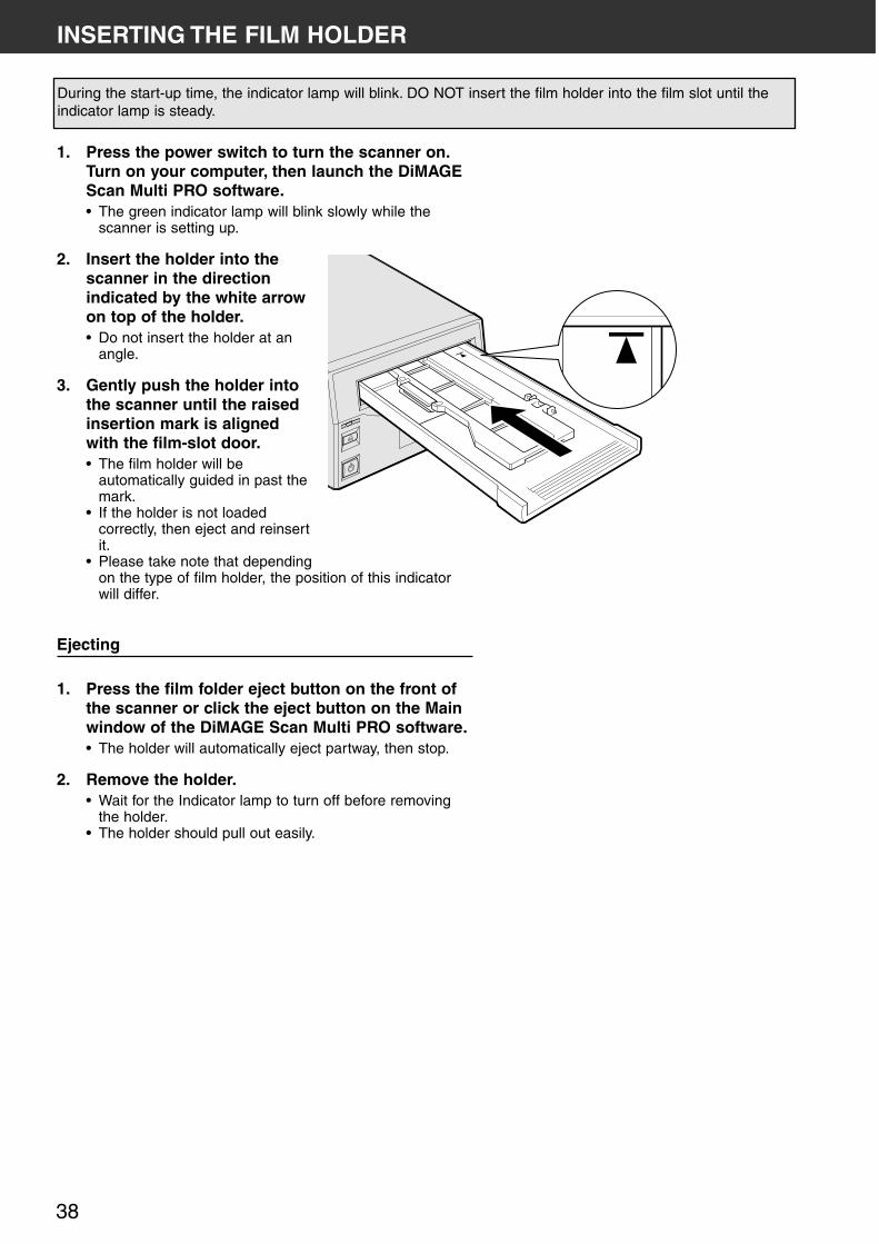
During the start-up time, the indicator lamp will blink. DO NOT insert the film holder into the film slot until theindicator lamp is steady.
1. Press the power switch to turn the scanner on.Turn on your computer, then launch the DiMAGEScan Multi PRO software.• The green indicator lamp will blink slowly while the
scanner is setting up.
2. Insert the holder into thescanner in the directionindicated by the white arrowon top of the holder.• Do not insert the holder at an
angle.
3. Gently push the holder intothe scanner until the raisedinsertion mark is alignedwith the film-slot door.• The film holder will be
automatically guided in past themark.
• If the holder is not loadedcorrectly, then eject and reinsertit.
• Please take note that dependingon the type of film holder, the position of this indicatorwill differ.
Ejecting
1. Press the film folder eject button on the front ofthe scanner or click the eject button on the Mainwindow of the DiMAGE Scan Multi PRO software.• The holder will automatically eject partway, then stop.
2. Remove the holder.• Wait for the Indicator lamp to turn off before removing
the holder.• The holder should pull out easily.

DiMAGE Scan Multi PRO 39
SETTING THE FILM FORMAT/FILM TYPE
SELECTING THE FILM FORMAT
1. Select the film format from the drop-down list.• The Index window (see page 42) will appear if 35mm,
6x4.5, 6x6, 6x7, 6x8, 6x9, Multi Format 35mm or MultiFormat 6x9 is selected.
• The following list shows the film formats and appropriateholders for scanning.
Selecting the Holder Type
When 6x4.5, 6x6, 6x7, 6x8 or 6x9 is selected in the filmformat, select the holder type.
1. Select the holder type from the drop-downlist in the main window.• The available holder types are with Glasses or
Glassless.
Film format Holder type
35mm 35 mm film holder FH-P1 orSlide mount holder SH-P1
6x4.5, 6x6, 6x7, 6x8,6x9Multi Format 35mm, Multi Format 6x9
Universal holder UH-P1, other attachments and masks suited foreach film.

40
Film format File type
35mm, 6x4.5, 6x6, 6x7, 6x8,6x9
Colour Negative, Slide Film, B&W Negative, B&W Positive
Multi Format 35mm, Multi Format 6x9
TEM Film, Transparent Media, Colour Negative, Slide Film, B&WNegative, B&W Positive
SETTING THE FILM FORMAT/FILM TYPE
SELECTING THE FILM TYPE
1. In the Main window, select the type of film fromthe drop-down list.• The film type options differ according to the film format
currently selected.
LIST OF USABLE FILMS
(*1)
(*2)
(*1)
Possible to scan the entire area at a time.Possible to scan partly by moving the film.Possible to scan the entire area although it is not normal method.Possible to scan the centre area alone.Not possible to scan.
*1 Equivalent to in actual scanning.*2 Equivalent to in actual scanning.
Film type
120/220
35mm
Full panorama
APS
16mm
Minox
Electronmicroscope
Aperture guard
4 x 5
Aperture guard
APS
6 x 4.5, 6 x 6,6 x 7, 6 x 8,6 x 9
Slide
Strip
Strip
Strip
Strip
Strip
59x81.5
59x163
59x163
82x118
For microfilm
for 120/220
Cartridge
Type Strip
Holder type
SlideUniversal 120/220 Universal Multi-format
with Glass Glassles Multi-f. 35mm Multi-f. 6x9
DiMAGE Scan Multi PRO 41
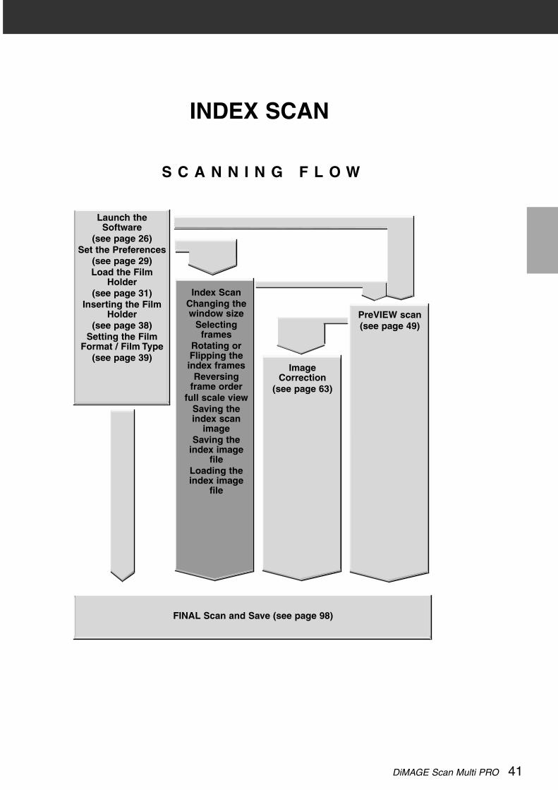
INDEX SCAN
S C A N N I N G F L O W
PreVIEW scan(see page 49)
ImageCorrection
(see page 63)
Index ScanChanging thewindow size
Selectingframes
Rotating orFlipping theindex frames
Reversingframe order
full scale viewSaving theindex scan
imageSaving the
index imagefile
Loading theindex image
file
FINAL Scan and Save (see page 98)
Launch theSoftware
(see page 26)Set the Preferences
(see page 29)Load the Film
Holder(see page 31)
Inserting the FilmHolder
(see page 38)Setting the Film
Format / Film Type(see page 39)

42
INDEX SCAN WINDOW
When 35mm is selected in the film format, index scan displays a scan of each image on thefilm holder in the Index tab. The time required for an index scan depends on the performanceof your computer.If you don’t want to index scan the entire strip, click on the appropriate image box in the indextab to select an image for prescanning or scanning.
• There are two options for making an index scan; Speed or Quality. Select the desiredoption in the Preference dialog box (see page 29).
Click on Index tab in the Main window.
THE INDEX TAB PART — NAMES OF PARTS
Rotate left button
Rotate right button
Flip Horizontal button
Flip Vertical button
Full-Scale View button
Reverse frame order button
Index Image frame
Frame number
Index Image area
Image Correction Job Loadbutton
Index File Load button
Save Index scan button
Save Index Image button

DiMAGE Scan Multi PRO 43
CHANGING THE WINDOW SIZE
Change the size of the Index tab window as desired. Theposition of the frames will change accordingly.
1. Click on the corner tab (lower-rightcorner) and drag to reach the desiredsize.
MAKING AN INDEX SCAN
1. Click on in the Main window.• All frames on the film folder will be scanned and appear
in the Index tab.
NOTE:• To cancel the index scan, press the
escape key ( - • Command and periodfor the Macintosh) until the CancellingIndex Scan message box appears.
• The completed index scans will appearin the Index tab.
• Frames that have not been indexscanned can still be selected forprescanning and scanning.
NOTE:• When the Full-Screen View button is not
clicked, the size and shape of the indexframes does not change.
• When the Full-Screen View button isclicked, the size of the index frameschanges automatically and all framesare displayed.

44
SCANNING THE IMAGE
SELECTING THE FRAMES
1. Click on an image to select it for scanning.• Selected images are surrounded by a dark grey frame.
2. Click on to scan the selected image (s).• The image will be opened in your photo application
software when the scanner’s driver software is closed.• Some photo applications can only acquire one image
at a time.
3. Refer to page 98 to save the scanned image (s).• Multiple scans will be saved using the selected file
name and numbered chronologically.Example: File_Name01, File_Name02, File_Name03...
CLICK CLICKNot selected
• Press the control key( key for theMacintosh) whileclicking to selectadditional frames forscanning.
• Press the control key( key for theMacintosh) whileclicking to deselect animage.
• Press the shift keywhile clicking to selectall the framesbetween the currentframe and the lastframe selected.
CLICK CLICKSelected
CLICK NOT SELECTED
SELECTED
CLICK
CLICKCLICK
NOTE:Click on to save the index as animage file (see page 46).• The image can be saved in JPEG or
BMP format (JPEG or PICT format for theMacintosh).
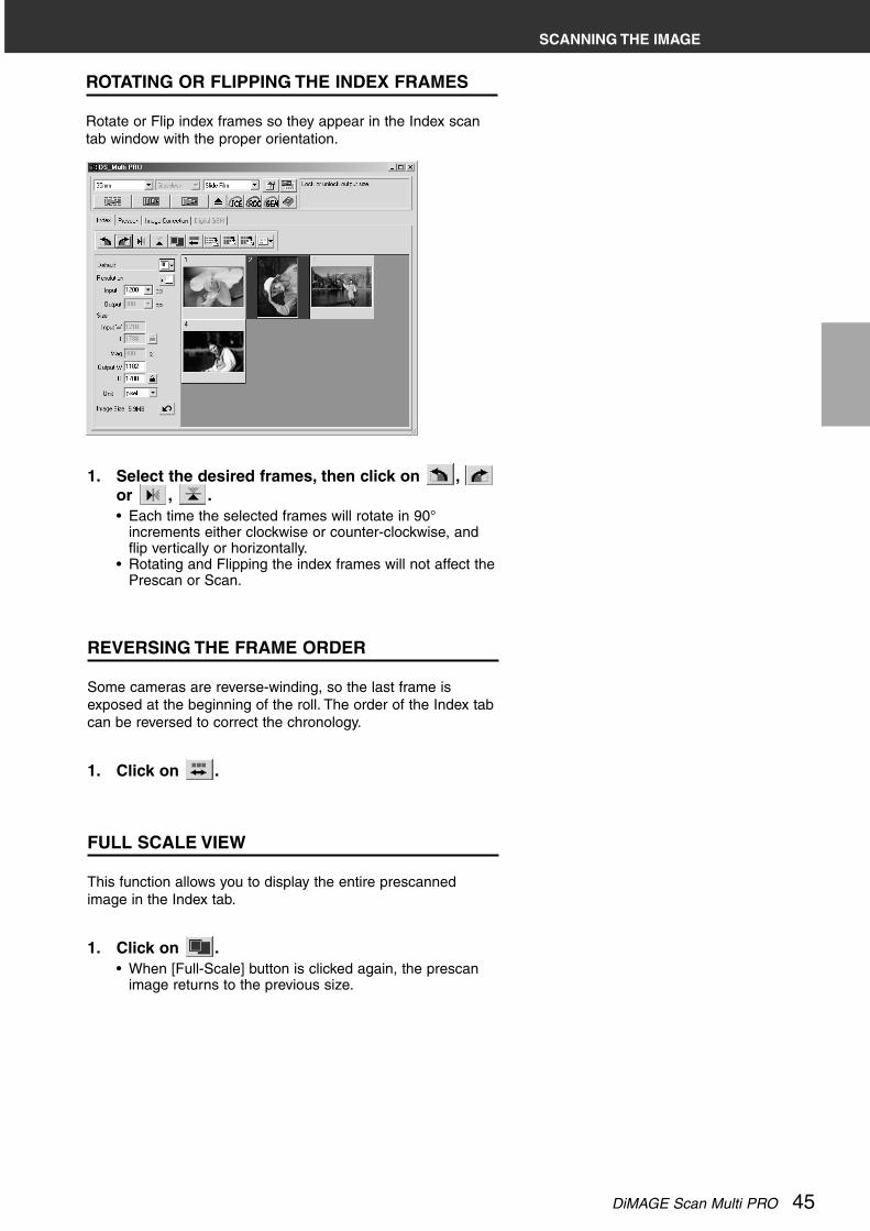
DiMAGE Scan Multi PRO 45
1. Select the desired frames, then click on ,or , .• Each time the selected frames will rotate in 90°
increments either clockwise or counter-clockwise, andflip vertically or horizontally.
• Rotating and Flipping the index frames will not affect thePrescan or Scan.
ROTATING OR FLIPPING THE INDEX FRAMES
Rotate or Flip index frames so they appear in the Index scantab window with the proper orientation.
REVERSING THE FRAME ORDER
Some cameras are reverse-winding, so the last frame isexposed at the beginning of the roll. The order of the Index tabcan be reversed to correct the chronology.
1. Click on .
FULL SCALE VIEW
This function allows you to display the entire prescannedimage in the Index tab.
1. Click on .• When [Full-Scale] button is clicked again, the prescan
image returns to the previous size.
SCANNING THE IMAGE

46
SAVING THE INDEX SCAN IMAGE
When performing the index scan, all the thumbnail imagesdisplayed in the index window can be saved as an image file.
1. Click on in the Main window.• The standard file save dialog box for each operating
system will appear.
2. Enter the desired file name, select the filedestination and then click on [Save].• All the thumbnail images in the index window
will be saved in the selected location with thespecified file name.
Windows®
• For Windows, the file can be saved in theWindows® Bitmap (BMP) or JPEG format.
Macintosh• For Macintosh, the file can be saved in the
PICT or JPEG format.
The index scan images are arranged in the image fileto be saved as follows:• When there are 4 index frames, the frames are
arranged in in one line of four When there are sixframes, the frames are arranged in one line of six.
• A spacing of 50 pixels is allocated at the top, bottom,right and left sides of the window.
• The horizontal or vertical space between frames is100 pixels or 70 pixels respectively.
• The output resolution of the image file to be saved is 300 dpi.

DiMAGE Scan Multi PRO 47
SAVING THE INDEX IMAGE FILE
The index images displayed in the index tab can also be savedas an index file.
1. Click on in the Main window.• File types other than the Index Image file (*.idx) cannot
be selected in the “Save as Type” list box (or the fileformat pull-down menu).
2. Enter the desired file name, select the filedestination and then click on [Save].• When the index images are displayed, these
images are saved regardless of the film set inthe scanner.
• When the index images are not displayed, theindex images are saved after performing theindex scan.
• If there are index images which have not beenscanned yet, those images will be scanned andthen all index images including those images willbe saved.
• The index image file is saved in the originalformat of this software.

48
LOADING THE INDEX IMAGE FILE
The index file can be displayed in the index tab after loadingthe saved index file. The previously displayed preview imagesare erased.
1. Click on in the Main window.• The standard file open dialog box for each operating
system will appear.
2. Select the index file to be load and then click on[Open].• When the previous index scan image is displayed, the
image is replaced with the current loaded image.

DiMAGE Scan Multi PRO 49
PREVIEW SCAN
S C A N N I N G F L O W
PREVIEWSCAN
Rotating theImage
Flipping theImage
Full screenviewing,
Magnifying orReducing the
viewScrolling the
ImageAE-Exposure
lockAE area lock
Auto croppingCropping the
ImageCropping the
prescan imageFocus –
Point AF (autofocus)
Focus – ManualDisplaying
frame numberRGB/CMY
information
IMAGECORRECTION(see page 63)
INDEX SCAN(see page 41)
FINAL Scan and Save (see page 98)
Launch theSoftware
(see page 26)Set the
Preferences(see page 29)Load the Film
Holder(see page 31)
Inserting the FilmHolder
(see page 38)Setting the Film
Format / Film Type(see page 39)

50
PRESCAN WINDOW
THE PRESCAN TAB PART — NAMES OF PARTS
Prescanning creates a scan of the image to which you can apply and view colour, contrast,orientation, and brightness corrections before clicking on the Scan button. This ensures thatfinal scan will be the best it can be.
Click on the Prescan tab in the Main window.
Rotate Left button
Rotate Right button
Flip Horizontal button
Flip Vertical button
Full-Scale View button
Zoom button
Grab button
Frame number indicator
RGB/CMY display
Zoom prescan button
Auto Cropping button
Manual Focus button
Point AF button
AE Lock button
AE Area Lock button

DiMAGE Scan Multi PRO 51
1. Click on in the Main window.
The prescanned image will appear in the Prescan tab.
MAKING A PRESCAN
NOTE:Press Ctrl when prescanning ( on theMacintosh) to see CMY values in theRGB/CMY display.

52
ROTATING THE IMAGE
Click on the and buttons to correct the orientation ofyour image before scanning. Changes will be reflected in theprescan image.
Click on to rotate the image 90° clockwise.
Click on to rotate the image 90° counter-clockwise.

DiMAGE Scan Multi PRO 53
FLIPPING THE IMAGE
The and buttons let you flip the image left to right ortop to bottom before scanning. Changes will be reflected in theprescan image.
Click on to flip the image top to bottom.
Click on to flip the image left-to-right.
• The image is upside downcompared to the originalprescan.
• Image is reversed comparedto the original scan.

54
FULL SCREEN VIEW
This function allows you to display the entire prescannedimage in the Prescan tab.
1. Click on .• The prescan image is magnified so that it fits in the Main
window.• When [Full-Screen] button is clicked again, the prescan
image returns to the previous size.
MAGNIFYING OR REDUCING THE VIEW
Use the zoom button to increase or reduce the imagemagnification
.Zooming In
1. Click on .• The pointer will change to .
2. Click anywhere on the image to zoomin.• The clicked position will be the centre of the
magnified view in the Prescan tab.• The + disappears from the magnifier icon when the
maximum image magnification has been reached.
Zooming Out
1. Press and hold the Ctrl key (option key on theMacintosh) to reduce the imagemagnification.• The pointer will change to .
2. Click anywhere on the image to zoomout.• The – disappears from the magnifier icon
when the minimum image magnification hasbeen reached.
FULL SCREEN VIEWING, MAGNIFYING OR REDUCING THE VIEW

DiMAGE Scan Multi PRO 55
Use the grab button to scroll an enlarged image.• The grab button can only be selected when the image has been magnified beyond the
limits of the Prescan tab.
SCROLLING THE IMAGE
1. Click on in the Prescan image display area.• The pointer will change to .
2. Click on and drag the image to thedesired location.

56
AE Lock allows you to lock an auto exposure value.Once the auto exposure is locked, the multiple images on the same film will be scanned withthe same exposure settings when performing the prescan and the final scan. With the AE lockfunction, for example, when scanning a backlit scene or a film to which exposure adjustmentshave been made, you can obtain a scanned image which reflects the exposure correctionmade when taking the photograph.
AE (Auto Exposure) function is performed in the following cases:• When prescanning negative film.• When prescanning colour positive film, where AUTO EXPOSE FOR SLIDES has been
selected in the preferences.
SETTING THE AE-LOCK
After prescanning the image…
1. Click on .• cannot be selected until an image has been
prescanned.
2. Select another image, then click on .• The locked exposure setting will apply to the selected
prescan image.• The prescan and the final scan will be performed with the
locked exposure setting until the AE Lock function iscancelled by clicking on the AE lock button again.
• When [Auto Expose for Slides] in the Preferences (seepage 29) is not checkmarked, the AE lock function is notavailable with positive film.
Images will be scanned using the AE lock settings until AElock is cancelled or the scanner is reinitialized.
CANCELLING THE AE-LOCK
1. Click on .
2. Click on to prescan the image again.
AUTO-EXPOSURE LOCK

DiMAGE Scan Multi PRO 57
AE AREA LOCK
Auto exposure can be based on a specified area in the prescanned image.Perform the procedure below after prescanning the image.
1. Click on .
2. Press the Shift key.• The AE area is indicated by an unbroken line, whereas
the cropping area is indicated by a dashed line.
3. While pressing down the Shift key, change theAE area.• The operation is the same as that of changing the
cropping area except that the shift key should be used.• For details, see “Cropping” (see page 58).
58
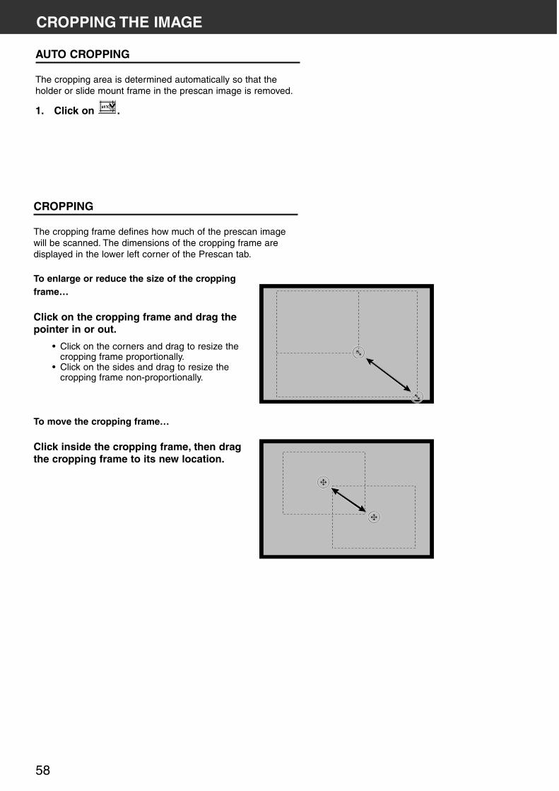
CROPPING
The cropping frame defines how much of the prescan imagewill be scanned. The dimensions of the cropping frame aredisplayed in the lower left corner of the Prescan tab.
To enlarge or reduce the size of the croppingframe…
Click on the cropping frame and drag thepointer in or out.
• Click on the corners and drag to resize thecropping frame proportionally.
• Click on the sides and drag to resize thecropping frame non-proportionally.
To move the cropping frame…
Click inside the cropping frame, then dragthe cropping frame to its new location.
CROPPING THE IMAGE
AUTO CROPPING
The cropping area is determined automatically so that theholder or slide mount frame in the prescan image is removed.
1. Click on .
DiMAGE Scan Multi PRO 59
CROPPING THE IMAGE
CROPPING THE PRESCAN IMAGE
A more precise prescan image can be displayed byprescanning the cropped area again.
1. Click on .• After the cropped area is prescanned again, a more
precise prescan image is displayed.
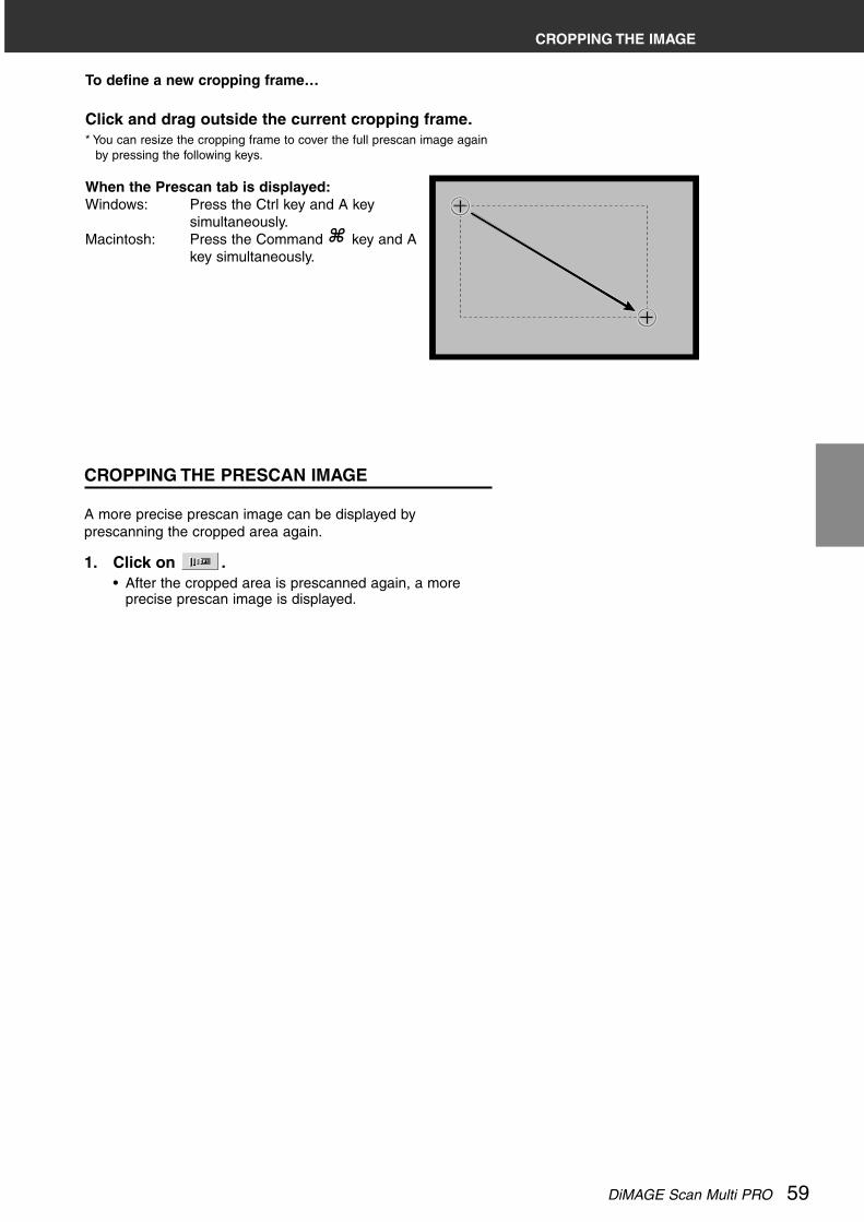
To define a new cropping frame…
Click and drag outside the current cropping frame.* You can resize the cropping frame to cover the full prescan image again
by pressing the following keys.
When the Prescan tab is displayed:Windows: Press the Ctrl key and A key
simultaneously.Macintosh: Press the Command key and A
key simultaneously.

60
FOCUS
The DiMAGE Scan Multi PRO uses the CCD sensor for autofocus.Autofocus uses the centre of the image to determine focus. Normally, this results in anexcellent scan because the film plane is flat. However, if the film is warped or curled, or ifAutofocus is turned off in the preferences, focus may not be accurate. In this case, the focusadjustment should be performed again using the point AF or Manual Focus function.
• Automatic autofocus can be turned on and off in the Preferences (see page 29).
POINT AF
This allows you to use autofocus on a specific area of theimage
1. Click on .• The pointer will change to the Point AF icon.• Click on [Point AF] button again to escape the function.
2. Click on the area of the image you wish to be insharp focus.• Autofocus will begin, then a new prescan will start.• The prescanned image will appear in the Prescan tab
when complete.
DiMAGE Scan Multi PRO 61
FOCUS
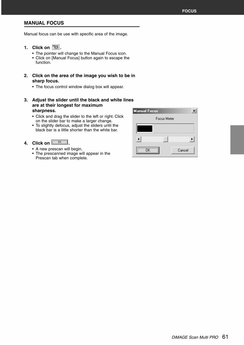
MANUAL FOCUS
Manual focus can be use with specific area of the image.
1. Click on .• The pointer will change to the Manual Focus icon.• Click on [Manual Focus] button again to escape the
function.
2. Click on the area of the image you wish to be insharp focus.• The focus control window dialog box will appear.
3. Adjust the slider until the black and white linesare at their longest for maximumsharpness.• Click and drag the slider to the left or right. Click
on the slider bar to make a larger change.• To slightly defocus, adjust the sliders until the
black bar is a little shorter than the white bar.
4. Click on .• A new prescan will begin.• The prescanned image will appear in the
Prescan tab when complete.

62
DISPLAYING FRAME NUMBER
When 35mm is selected the film format, this function allowsyou to display the current frame number and total framenumber.
1. To display the next frame, click on .
2. To display the previous frame, click on .
RGB/CMY INFORMATION
The RGB information from the pointer position is always displayedin the Prescan tab. The information is described in brightnesslevels from 0 to 255. However, the display can be changed toshow CMY information.
1. Press and hold the Shift key (Command keyon the Macintosh) with the Prescan tab open.The RGB information will change to CMY.

DiMAGE Scan Multi PRO 63
IMAGE CORRECTION
I M A G E C O R R E C T I O N F L O W
IMAGECORRECTIONTone curves
and histogramBrightness/contrast /
colour balanceHue /
saturation/lightnessVariation
correctionSelective
colourcorrection
Unsharp maskSnapshot
Cancelling theimage
correctionFull-screen
viewJob save / job
loadDigital
ICE/ROC/GEM
INDEX SCAN(see page 41)
FINAL Scan and Save (see page 98)
PREVIEWSCAN
(see page 49)
LAUNCH THESOFTWARE
(see page 26)Set the
Preferences(see page 29)Load the Film
Holder(see page 31)
Inserting the FilmHolder
(see page 38)Setting the Film
Format / Film Type(see page 39)

64
IMAGE CORRECTION WINDOW
THE IMAGE CORRECTION TAB PART — NAMES OF PARTS
This scanner gives you three options for correcting the brightness, contrast, and colourbalance of the final scan.
Click on the Image Correction tab in the Main window.
Selective Colour button
Variations button
Hue/Saturation/LightnessCorrection button
Brightness/Contrast/ColourBalance Correction button
Tone Curves/HistogramCorrection button
Snapshot display area
Unsharp Mask button
Undo button
Redo button
RGB/CMY value display
Frame Number indicator
Full-Screen View button
Pre/Post CorrectionComparison Display button
Image Correction Job Loadbutton
Image Correction Job Savebutton
Snapshot button
Correction Reset button

DiMAGE Scan Multi PRO 65
TONE CURVES AND HISTOGRAM
When the Tone curves/Histogram Correction button is clicked, the Tone Curves and Histogramdialog box is displayed.The Tone Curves part allows you to change the tone curves and directly correct the outputvalue.The Histogram part allows you to specify the input and output area from the informationincluded in a film and correct images. Also, this dialog box displays the histogram of the imagearea inside the cropping frame in each RGB colour. The level is indicated in 256 colour steps(0 to 255) from left to right side.The tone curves and histogram are linked to each other so that when the tone curve iscorrected, the histogram is automatically corrected.
Click on in the Image Correction tab.
THE TONE CURVES AND HISTOGRAM DIALOG BOX — NAMES OF PARTS
Channel list box
Tone curves pallet
Tone curves
Input Gamma slider
Histogram
Input Shadow slider
Output Shadow slider
Histogram RGB displaybutton
Tone curves/SmoothCurve button
Freehand curve button
Black point button
Grey point button
White point button
Apply button
Input Highlight slider
Input Shadow text box
Input Gamma text box
Input Highlight text box
Output Shadow text box
Output Highlight text box
Output Highlight slider
Reset button
Auto Setting button
Grey scale

66
TONE CURVES AND HISTOGRAM
CORRECTING THE TONE CURVES
Changing the shape of a correction curve changes the outputlevel for each corresponding input level. Changing the shape ofthe red, green, or blue curves affects colour balance of theimage. Changes to the RGB curve affect the image contrastand brightness.
1. Click on the arrow next to the channel to displaythe available channel (RGB, R, G, B).
2. Select the channel of the colour to be corrected.
3. Click and drag the portion of the curve to bechanged.
• The coordinate value of the cursor is displayed from 0 to255.
• The correction made by changing the tone curves isapplied to the prescan image.
• You can also change the tone curves by freehand.
CHANGING THE TONE CURVES BY FREEHAND
This function allows you to draw tone curves by freehand.
1. Select the channel of the colour (R, G, B, RGB) tobe corrected from the channel selection menu.
2. Click on .• The cursor changes to the pencil shape.
3. Draw the desired curve by dragging.
• To smooth out the curve points, click on .• The change will be reflected in the prescan image.

DiMAGE Scan Multi PRO 67
TONE CURVES AND HISTOGRAM
SETTING THE WHITE, BLACK OR GREY POINTS
White point (highlight point) indicates the section you want tolighten, Black point (shadow point) the section you want todarken, and Grey the section you want to have as neutral tone.An image with no highlight or shadow will not be clear andappear dull. You can correct the image by adjusting the Whitepoint/Black point/Grey point buttons to enhance the highlight orshadow point so that the image will have good contrastand not be all white or black. Also if the image has toomuch contrast, you can correct it by weakening thehighlight or shadow point.
• Changes are automatically applied to the prescanimage.
Setting the White Point
1. Double-click on .
• The Point Value Setting dialog box is displayed.• The initial value of the White point is 255 in each R, G
and B.
2. Input the desired white point value.
3. Click on .
• The cursor changes to the white dropper shape.
4. Click the desired highlight point of the image.
• The image is corrected so that the point you clicked isthe highlight point. The colour of the highlight point is thewhite dropper value you input in step 2.
• The change will be reflected in the prescan image.
• You need to identify the true highlight points of the image, notpure white points that have no detail, such as reflectionpoints. White with no detail is called specular white and inkwill not be used in these parts when printing.
• Normally, if you set each R, G, B colour to 250 to 253, whitewill have less brightness. You may lose the gleam of a whitecup.
Point Value Setting dialog box
• When the film type is set to thecolour mode.
• When the film type is set to themonochrome mode.
Setting the Black point
1. Double-click on .
• The Point Value Setting dialog box is displayed.• The initial value of the Black point is 0 in each R, G
and B.
2. Input the desired black point value.
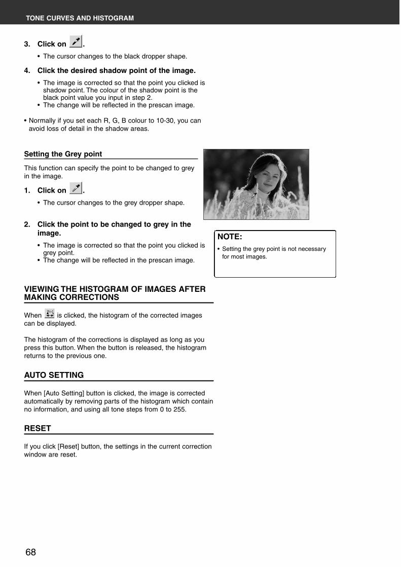
68
TONE CURVES AND HISTOGRAM
Setting the Grey point
This function can specify the point to be changed to greyin the image.
1. Click on .
• The cursor changes to the grey dropper shape.
2. Click the point to be changed to grey in theimage.
• The image is corrected so that the point you clicked isgrey point.
• The change will be reflected in the prescan image.
VIEWING THE HISTOGRAM OF IMAGES AFTERMAKING CORRECTIONS
When is clicked, the histogram of the corrected imagescan be displayed.
The histogram of the corrections is displayed as long as youpress this button. When the button is released, the histogramreturns to the previous one.
AUTO SETTING
When [Auto Setting] button is clicked, the image is correctedautomatically by removing parts of the histogram which containno information, and using all tone steps from 0 to 255.
RESET
If you click [Reset] button, the settings in the current correctionwindow are reset.
3. Click on .
• The cursor changes to the black dropper shape.
4. Click the desired shadow point of the image.
• The image is corrected so that the point you clicked isshadow point. The colour of the shadow point is theblack point value you input in step 2.
• The change will be reflected in the prescan image.
• Normally if you set each R, G, B colour to 10-30, you canavoid loss of detail in the shadow areas.
NOTE:• Setting the grey point is not necessary
for most images.

DiMAGE Scan Multi PRO 69
TONE CURVES AND HISTOGRAM
CORRECTING THE HISTOGRAM
The input slide bar has the Input shadow slider, Input gammaslider and Input Highlight slider. The output slide bar has theOutput Highlight slider and Output shadow slider.The image can be corrected by dragging the slider or inputtingthe value in the text box.The change will reflect the prescan image.
1. Drag the slider to move it to the desired level orinput the value in the text box.• The change will be reflected in the prescan
image.* For example, if you use the input Highlight slider and input
shadow slider to remove areas which contain no pixels (flatline at left or right) the original colour will be betterrepresented.Although the output slider does not normally need to beadjusted, use it according to the characteristics of theoutput equipment. For example, use the output slider whenthe black part is not printed clearly with the 0 setting in theblack level. (In this case, adjust the Output level by movingthe Output Shadow slider to the right slightly while checking thecorrection result).
Input Level Histogram
Displaying the Histogram of Each R, G, B colour
1. Click on .
• When is clicked again, thehistogram of each R, G, B channeldisappears.
2. By dragging the Input Highlightslider (right) or the InputShadow slider (left) in each R, G,B channel or inputting the valuedirectly in each text box, theHistogram RGB can becorrected.• The change will be reflected in the
prescan image displayed in theImage Correction display area.
• The change corrected in each R, G, B channel will alsobe reflected in each corresponding tone curve.

70
BRIGHTNESS / CONTRAST / COLOUR BALANCE
Brightness, Contrast adjusts the brightness and contrast of the whole image.By adjusting the ratio of each RGB colour, you can correct the greenness or redness of the wholeimage, as well as overlapping of certain colors (colour overlap).
Click on in the Image Correction tab.
THE BRIGHTNESS, CONTRAST AND COLOURBALANCE CORRECTION DIALOG BOX — NAMES OFPARTS
Correction Result LUT (LookUp Table) display
Post-Correction Grayscalecontrol sample
Pre-Correction Grey scalecontrol sample
Brightness slider
Contrast slider
Colour Balance (R, G, B) slider
Brightness text box
Contrast text box
Colour Balance text box
Reset button
Auto Setting button

DiMAGE Scan Multi PRO 71
1. Drag each Brightness, Contrast or Colourbalance (R, G, B) slider, or input the desired valuein the text box.• The change will be reflected in the prescan image.• Moving the Brightness, Contrast or Colour balance (R,
G, B) slider changes “Post-Correction Greyscale” and“Correction Result LUT”.
Brightness correction:By dragging the Brightness slider to the right (or inputting a bigplus number in the text box), th brightness of the image israiesed.
Contrast correction:By dragging the Contrast slider to the right (or inputting a bigplus number in the text box), bright areas become brighter anddark areas become darker
RGB colour balance correction:By dragging the Colour Balance slider to the right (or inputtinga big plus number in the text box), the contect of each channelis increased, to emphasise each colour.
Correction Result LUT
The colour of the image is changed as shown in the CorrectionResult LUT.The correspondence between the colour displayed on the Pre-Correction Grayscale and Post-Correction Grayscale appearson the Correction Result LUT.
BRIGHTNESS / CONTRAST / COLOUR BALANCE
AUTO SETTING
When [Auto Setting] button is clicked, the brightness andcontrast of the image is corrected automatically according tothe lightness without changing the colour balance.
RESET
If you click [Reset] button, the settings in the current correctionwindow are reset.

72
HUE / SATURATION / LIGHTNESS
You can adjust the 3 colour elements Hue (tone of colour), Saturation (vividness), and Lightness (brightness)separately. This is suitable for when the colour seems dull and you wish to add vividness. It is necessary tochoose a good combination of Hue, Saturation, and Lightness.
Click on in the Image Correction tab.
THE HUE, SATURATION, LIGHTNESS CORRECTION DIALOGBOX —NAMES OF PARTS
1. Drag each Hue, Saturation or Lightness slider, orinput the desired value in the text box.• The change will be reflected in the prescan image.• To change the colour, move the Hue, Saturation or
Lightness -level slider (or input the desired value in thetext box).Moving the slider changes “Pre-Correction ColourSample” and “Post-Correction Colour Sample”.
Hue-level slider
Saturation-level slider
Lightness-level slider
Pre-Correction Colour Sample
Post-Correction Colour Sample
Hue-level text box
Saturation-level text box
Lightness-level text box
Reset button
Auto Setting button

DiMAGE Scan Multi PRO 73
AUTO SETTING
When [Auto Setting] button is clicked, the saturation of theimage is corrected automatically without changing the hue andlightness.
HUE / SATURATION / LIGHTNESS
RESET
If you click [Reset] button, the settings in the current correctionwindow are reset.
Hue correction:Dragging the Hue slider, changes the colour of the imagedisplayed in Pre-Correction Colour Sample, as shown in Post-Correction Colour Sample. When the Hue slider is dragged tothe rightmost or leftmost side, the hue of the image isreversed.
Saturation correction:Dragging the saturation slider to the right (or inputting a bigplus number in the text box) icreases the intensity of the imagecolours.Dragging the saturation slider to the left (or inputting a bigminus number in the box) reduces the intensity of the colours.
Lightness correction:By dragging the Lightness slider to the right (or inputting a bigplus number in the text box), the lightness of the image israised.
Pre-Correction Colour Sample and Post-Correction Colour Sample
The colour displayed in “Pre-Correction Colour Sample” ischanged as shown in “Post-Correction Colour Sample”.

74
SELECTING THE ITEM TO BE CORRECTED
Colour Balance , brightness, contrast and saturation can all beselected for correction in the Variations screen.However, colourbalance and saturation are not available when using themonochrome film.
1. Click on the arrow next to the correction list box.The available correction items are displayed.
2. Click the item you wish to correct.A number of frames of variation images correctedaccording to the selected correction item are displayed.
VARIATION CORRECTION
A number of images showing different variations are displayed , around the currently correctedprescan image. You can correct the image while comparing with the variation images.
Click on in the Image Correction tab.
THE VARIATION DIALOG BOX — NAMES OFPARTS
Variation Amount Control slider
Correction list box
Pre/Post Correction ImageDisplay area
Variation Amount Control textbox
Limit Indication check box
Reset button
CHANGING THE SIZE OF THE CORRECTIONINCREMENT
The size of the correction increments can be changed bymoving the Variation Amount Control slider. The desiredamount can also be input (10 to 20) in the text box.

DiMAGE Scan Multi PRO 75
VARIATION CORRECTION
COLOUR BALANCE CORRECTION
Six images that have been corrected by one-step in eachRGBCMY direction the centre current image are displayed.
1. Select colour balance.• The corrected 6 frames of variation images are
displayed.
2. Click the image in the direction you want tocorrect from the 6 frames of the variationimages except for the centre image.• The image you clicked is placed in centre and 6
new variation images appear corrected by one-step in each direction.
3. Correct the image properly by repeating theoperation in step 2.
BRIGHTNESS & CONTRAST CORRECTION
Eight images in which brightness and contrast have beencorrected by one-step in each direction from the centre imageare displayed.The variation images on the left and lower sides of the centreimage show the – correction effect, and on the right and uppersides of the centre image show the + correction effect.
1. Click the image in the direction you wantto correct from the 8 variation images,except the centre image.• The image you clicked is placed in the centre
and 8 new frames corrected in each directionare displayed.
2. Correct the image properly by repeatingthe operation in step 1.

76
SATURATION CORRECTION
Two imageswith saturation correction are displayed on the rightand left sides of the centre image. The variation image on theleft side shows reduced saturation, and on the right side showsincreased saturation.
1. Click the image in the direction you wantto correct, except for the image in thecentre.• The image you clicked is placed in the centre
and 2 new variation images are displayed.
2. Correct the image properly by repeatingthe operation in step 1.
VARIATION CORRECTION
RESET
If you click [Reset] button, the settings in the current correctionwindow are reset.

DiMAGE Scan Multi PRO 77
This feature separates the colour region into 7 groups, Red, Green, Blue, Cyan, Magenta,Yellow and Black. You can adjust the colour range of each processed colour Cyan, Magenta,Yellow, and Black against the separate colour groups. You can use this if you wish to correct acertain colour only and not the whole picture, or if you wish to remove an unwanted colourfrom a particular colour. For instance, if you want the sky look vividly blue instead of purplish,decrease the component amount of Magenta from Blue to obtain a very blue sky.
Click on in the Image Correction tab.
THE SELECTIVE COLOUR CORRECTION DIALOG BOX — NAMES OF PARTS
SELECTIVE COLOUR CORRECTION
1. Click on the arrow next to the Colourlist box to display the colour range tobe corrected.
2. Drag the Cyan (C), Magenta (M), Yellow(Y) or Black (K) slider or input thedesired value in the text box.• The values from -100 to 100 can be input.• The change will not be reflected in the
prescan image.
Colour list box
CMYK slider
RESET
If you click [Reset] button, the settings in the current correctionwindow are reset.
CMYK text box
Reset button

78
1. Drag the Amount, Radius, Threshold level or DarkPart Protection level slider or input the desiredvalue in the text box.• The values from 0 to 500 for the Amount, from 0.1 to 5
for the Radius and from 0 to 255 for the Threshold levelor Dark Part Protection level can be input respectively.
• The change will not be reflected in the prescan image.
UNSHARP MASK
Unsharp Mask can increase definition of the image to make it clearer. It is useful if the image isslightly unfocused.
Click on in the Image Correction tab.
THE UNSHARP MASK DIALOG BOX — NAMES OF PARTS
Amount Level slider and text box
Radius Level slider and text box
Threshold Level slider and textbox
Dark Part Protection Levelslider and text box
Reset button

DiMAGE Scan Multi PRO 79
Amount:If you adjust the slider to increase (to the right), Pixels increasing the levelof contrast will become larger. If you increase the value too much, Pixelation(the Pixels image becoming noticeably rough) will occur. Normally, werecommend 150 to 200% for highly processed print images.
Radius:If you adjust the slide to increase (to the right) or input a value, the edge ofthe Pixel will become sharper. Set it to determine how the sharpening effectis extended around each pixel. Normally, we recommend 1 to 2 for highlyprocessed print images. This alteration cannot be recognized much on aprint as it will be on the screen.
Threshold level:If the difference between the surrounding pixels is greater than that of thethreshold level, that pixel is recognized as a requiring sharpening. Thisrestricts the effect to places where it is reduced.
Dark Part Protection level:This limits the sharpening effect, so that only pixels whose light level isgreater then the selected level are sharpened.
RESET
If you click [Reset] button, the settings in the current correctionwindow are reset.
UNSHARP MASK

80
SNAPSHOT
When the Snapshot button is clicked, the current prescan image is stored in the SnapshotDisplay Area temporarily and displayed as a thumbnail.When the thumbnail in the Snapshot Display Area is double-clicked, that image is displayed inthe Prescan tab.This is convenient when storing the image correction temporarily while processing, or whencorrecting the image again after going back to a certain step.
STORING IN THE SNAPSHOT DISPLAY AREATEMPORARILY
1. Click on .in the ImageCorrection tab.• The displayed prescan image is
displayed in the Snapshot DisplayArea temporarily.
DISPLAYING THE IMAGE STOREDTEMPORARILY AS A PRESCAN IMAGE
1. Click on the thumbnail in theSnapshot Display Area.• The displayed prescan image is
deleted and the thumbnail image isdisplayed as a prescan image.
Snapshot Display Area 1
Snapshot Display Area 2

DiMAGE Scan Multi PRO 81
CANCELLING THE IMAGE CORRECTION
CANCELLING THE IMAGE CORRECTION
When is clicked, the current image correction is cancelledand the image returns to the previous one.
REDO THE CORRECTION
When is clicked, the cancelled image correction can beresumed.
DELETE THE IMAGE CORRECTION
When in the Image Correction tab is clicked, all the imagecorrections are deleted and the image returns to the initialstate.

82
1. Click on .in the Image Correction tab.• When is clicked, the size of the pre and post
correction image is automatically changed according tothe size of the Main window.
CHECKING THE CORRECTION RESULT WHILELINING UP IMAGES
When is clicked, the Image correction tab is divided intoright and left sides, the pre-correction image is displayed onthe left side, and post-correction image is displayed on theright side.
FULL-SCREEN VIEW
This function allows you to display a full screen view of the corrected image in the ImageCorrection tab.

DiMAGE Scan Multi PRO 83
The image correction setting in the correction window can be saved as an image correctionjob. You can easily correct the image by loading the most appropriate previously savedcorrection job.
SAVING AN IMAGE CORRECTION JOB
1. Click on in the Image Correction tab.• The Register Image Correction Job dialog box is
displayed.
2. Input the job name and click on .• The current image correction setting is saved as an
image correction job.
JOB SAVE / JOB LOAD

84
JOB SAVE / JOB LOAD
LOADING IMAGE CORRECTION JOB
This function allows you to load the saved correction job andapply an image correction to the displayed image.
1. Click on in the Image Correction tab.• The Selected Image Correction Job dialog box is
displayed.
2. Select the Image Correction job and click on .
Image Correction job displayarea
Original image display

DiMAGE Scan Multi PRO 85
DIGITAL ICE / DIGITAL ROC / DIGITAL GEM
BEFORE USING THE DIGITAL ICE/ROC/GEM FUNCTION
WINDOWSWhen connecting with the SCSI interface
With Digital ICE/Digital ROC/Digital GEM function turned on.
With Digital ICE/Digital ROC/Digital GEM function, and loading with a 16-bit resolutionturned on.
When connecting with the IEEE1394 interface
With Digital ICE/Digital ROC/Digital GEM function turned on.
With Digital ICE/Digital ROC/Digital GEM function, and loading with a 16-bit resolutionturned on.
35mm
Multi Format 35mm
Multi Format 6x9
Minimum system requirements
CPU
Pentium 166MHz later
Pentium 166MHz later
Pentium 166MHz later
Memory Hard diskspace
128MB
256MB
256MB
1.2GB
2GB
4GB
Recommended system requirements
CPU
Pentium III later
Pentium III later
Pentium III later
Memory Hard diskspace
512MB
512MB
512MB
2GB
4GB
6GB
35mm
Multi Format 35mm
Multi Format 6x9
Minimum system requirements
CPU
Pentium 166MHz later
Pentium 166MHz later
Pentium 166MHz later
Memory Hard diskspace
256MB
256MB
256MB
2GB
3GB
6GB
Recommended system requirements
CPU
Pentium III later
Pentium III later
Pentium III later
Memory Hard diskspace
512MB
512MB
512MB
3GB
4GB
8GB
35mm
Multi Format 35mm
Multi Format 6x9
Minimum system requirements
CPU
Pentium II later
Pentium II later
Pentium II later
Memory Hard diskspace
128MB
256MB
256MB
1.2GB
2GB
4GB
Recommended system requirements
CPU
Pentium III later
Pentium III later
Pentium III later
Memory Hard diskspace
512MB
512MB
512MB
2GB
4GB
6GB
35mm
Multi Format 35mm
Multi Format 6x9
Minimum system requirements
CPU
Pentium III later
Pentium III later
Pentium III later
Memory Hard diskspace
256MB
256MB
256MB
2GB
3GB
6GB
Recommended system requirements
CPU
Pentium III later
Pentium III later
Pentium III later
Memory Hard diskspace
512MB
512MB
512MB
3GB
4GB
8GB

86
DIGITAL ICE / DIGITAL ROC / DIGITAL GEM
MACINTOSHWhen connecting with the SCSI interface
With Digital ICE/Digital ROC/Digital GEM function turned on.
With Digital ICE/Digital ROC/Digital GEM function, and loading with a 16-bit resolutionturned on.
When connecting with the IEEE1394 interface
With Digital ICE/Digital ROC/Digital GEM function turned on.
With Digital ICE/Digital ROC/Digital GEM function, and loading with a 16-bit resolutionturned on.
* With Macintosh, unused memory is the blank volume after the necessary memory for OS and applicationsbas been deducted.With Photoshop, assign the desired memory size adding the unused memory to the suggested memory sizeof the Photoshop.
35mm
Multi Format 35mm
Multi Format 6x9
Minimum system requirements
CPU
Power PC604 later
Power PC604 later
Power PC604 later
Memory Hard diskspace
96MB
192MB
192MB
1.2GB
2GB
4GB
Recommended system requirements
CPU
Power PC G4 later
Power PC G4 later
Power PC G4 later
Memory Hard diskspace
384MB
384MB
384MB
2GB
4GB
6GB
35mm
Multi Format 35mm
Multi Format 6x9
Minimum system requirements
CPU
Power PC604 later
Power PC604 later
Power PC604 later
Memory Hard diskspace
256MB
256MB
256MB
2GB
3GB
6GB
Recommended system requirements
CPU
Power PC G4 later
Power PC G4 later
Power PC G4 later
Memory Hard diskspace
512MB
512MB
512MB
3GB
4GB
8GB
35mm
Multi Format 35mm
Multi Format 6x9
Minimum system requirements
CPU
Power PC604 later
Power PC604 later
Power PC604 later
Memory Hard diskspace
96MB
192MB
192MB
1.2GB
2GB
4GB
Recommended system requirements
CPU
Power PC G4 later
Power PC G4 later
Power PC G4 later
Memory Hard diskspace
384MB
384MB
384MB
2GB
4GB
6GB
35mm
Multi Format 35mm
Multi Format 6x9
Minimum system requirements
CPU
Power PC604 later
Power PC604 later
Power PC604 later
Memory Hard diskspace
256MB
256MB
256MB
2GB
3GB
6GB
Recommended system requirements
CPU
Power PC G4 later
Power PC G4 later
Power PC G4 later
Memory Hard diskspace
512MB
512MB
512MB
3GB
4GB
8GB

DiMAGE Scan Multi PRO 87
1. Click on in the main window.• The Digital ICE function is turned on. When the preview
scan and final scan are performed, the image isdisplayed with the visable dust, scratches, figerprintsmold etc removed. However, this function has no effectwhen scanning a monochrome film.
• When the Digital ICE function is turned off, the scanningtime will be longer.
• Kodak Kodachrome cannot be used.• You can use the Digital ICE function for the following
types of B&W film only after the film has been developedin colour and scanned with the “Colour Negative” settingfor the film type. We cannot assure this procedure forother types of film.Kodak Select Black & White 400Kodak T400CNIllford XP2 Super
DIGITAL ICE
The Digital ICE (Image Correction Enhancement) function removes visible dust, scratches,fingerprints, mould, etc. from the surface of the image.
Digital ICE3TM, Digital ICETM, Digital ROCTM, and Digital
GEMTM are trademarks of registered trademarks and
techenolgies of Applied Science Fiction,Inc in U. S. A.

88
The Digital ROC (Reconstruction Of Colour) function is an image correction function that canrestore the colour quality of a faded image.If the colour of the film has faded with the passage of time, the changed colour can becorrected automatically by reconstructing colour when scanning so that a digital image withappropriate colour can be restored.
DIGITAL ROC
1. Click on in the Main window.• The Digital ROC function is turned on. When the preview
scan and final scan (see page 98) are performed, thecolour quality of a faded image is restored and thecorrected image is displayed.
• When scanning a B&W film, the Digital ROC function isnot available.
• When scanning a colour film when 16 bit linear isselected as the scanning mode in the Preferences, theDigital ROC function cannot be used.
• When the Digital ROC function is turned on, the settingsof “Auto Expose for Slides“ in the Preferences, thecolour matching, the AE Lock function whenprescanning (see page 56) or the AE Area Lock function(see page 57) are cancelled.
• When using the Digital ROC function, be sure andperform the prescan and adjust the focus with the PointAF or Manual Focus function (see pages 60 to 61)before the final scan. Putting a checkmark on “AutoFocus at Scan” in the Preferences is recommended.
• To turn off the Digital ROC function, click on the DigitalROC button again.
• The Digital ROC function may not always operateeffectively depending on the conditions of the film or theextent to which the colours are faded.
• Much more time is required for scanning when theDigital ROC function is turned on, compared with whenthat function is turned off.
• You can use the Digital ROC function for the followingtypes of B&W film only after the film has been developedin colour and scanned with the “Colour Negative” settingfor the film type. We cannot assure this procedure forother types of film.Kodak Select Black & White 400Kodak T400CNIllford XP2 Super
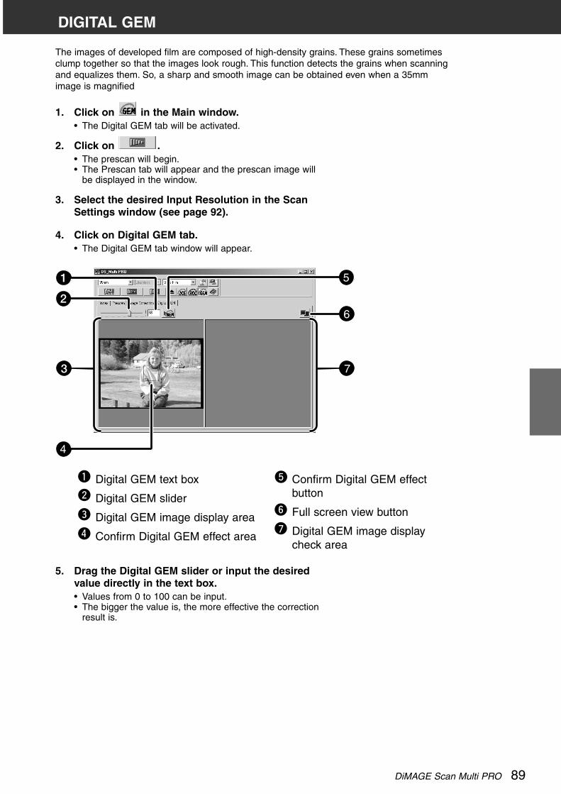
DiMAGE Scan Multi PRO 89
The images of developed film are composed of high-density grains. These grains sometimesclump together so that the images look rough. This function detects the grains when scanningand equalizes them. So, a sharp and smooth image can be obtained even when a 35mmimage is magnified
DIGITAL GEM
5. Drag the Digital GEM slider or input the desiredvalue directly in the text box.• Values from 0 to 100 can be input.• The bigger the value is, the more effective the correction
result is.
Digital GEM text box
Digital GEM slider
Digital GEM image display area
Confirm Digital GEM effect area
Confirm Digital GEM effectbutton
Full screen view button
Digital GEM image displaycheck area
1. Click on in the Main window.• The Digital GEM tab will be activated.
2. Click on .• The prescan will begin.• The Prescan tab will appear and the prescan image will
be displayed in the window.
3. Select the desired Input Resolution in the ScanSettings window (see page 92).
4. Click on Digital GEM tab.• The Digital GEM tab window will appear.
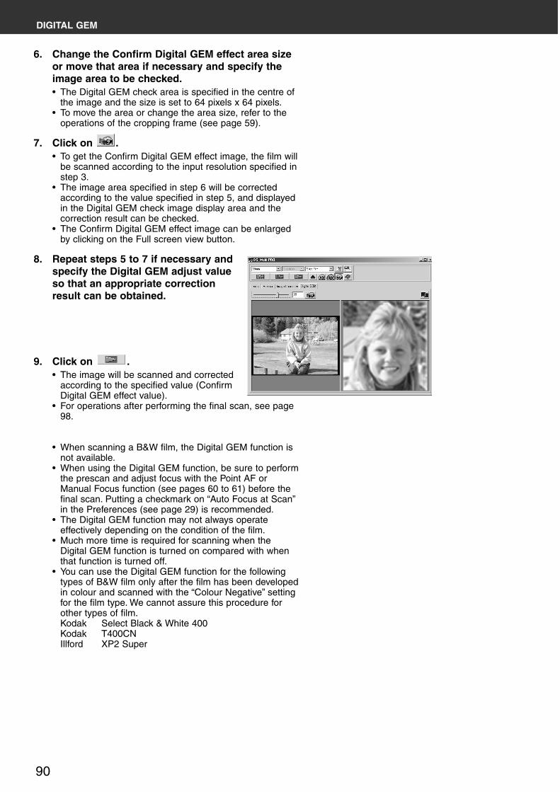
90
DIGITAL GEM
9. Click on .• The image will be scanned and corrected
according to the specified value (ConfirmDigital GEM effect value).
• For operations after performing the final scan, see page98.
• When scanning a B&W film, the Digital GEM function isnot available.
• When using the Digital GEM function, be sure to performthe prescan and adjust focus with the Point AF orManual Focus function (see pages 60 to 61) before thefinal scan. Putting a checkmark on “Auto Focus at Scan”in the Preferences (see page 29) is recommended.
• The Digital GEM function may not always operateeffectively depending on the condition of the film.
• Much more time is required for scanning when theDigital GEM function is turned on compared with whenthat function is turned off.
• You can use the Digital GEM function for the followingtypes of B&W film only after the film has been developedin colour and scanned with the “Colour Negative” settingfor the film type. We cannot assure this procedure forother types of film.Kodak Select Black & White 400Kodak T400CNIllford XP2 Super
6. Change the Confirm Digital GEM effect area sizeor move that area if necessary and specify theimage area to be checked.• The Digital GEM check area is specified in the centre of
the image and the size is set to 64 pixels x 64 pixels.• To move the area or change the area size, refer to the
operations of the cropping frame (see page 59).
7. Click on .• To get the Confirm Digital GEM effect image, the film will
be scanned according to the input resolution specified instep 3.
• The image area specified in step 6 will be correctedaccording to the value specified in step 5, and displayedin the Digital GEM check image display area and thecorrection result can be checked.
• The Confirm Digital GEM effect image can be enlargedby clicking on the Full screen view button.
8. Repeat steps 5 to 7 if necessary andspecify the Digital GEM adjust valueso that an appropriate correctionresult can be obtained.

DiMAGE Scan Multi PRO 91
FINAL SCAN
F L O W
SCAN SETTING
Creating a job
Deleting a job
Job type
CUSTOM WIZARD
FINAL SCAN

92
SCAN SETTINGS
The scan settings determine your final image’s resolution, dimensions, and file size, as well ashelping determine the image quality. You can select a Job (see pages 96, 110 to 123) to havethe scan settings selected for you or you can directly enter them into the Main window (Indextab or Prescan tab).
THE SCAN SETTINGS PART WINDOW — NAMES OF PARTS
Job Name list box
Input Resolution list box
Output Resolution list box
Input Size text box (W)
Input Size text box (H)
Magnification Size text box
Output Size text box (W)
Output Size text box (H)
Unit list box
Image Size display
Job Load button
Job Save button
Input size lock button
Output size lock button
Reset button

DiMAGE Scan Multi PRO 93
SCAN SETTINGS
Image resolution is the number of pixels per inch (ppi or dpi) that represent your scannedimage. The size of an image file is determined by its size (dimensions) and resolution.
The rule to follow when scanning is "bigger is better". To obtain the best results, set the outputresolution to the highest value your final output device (printer, monitor, etc.) can handle. Thedriver software automatically determines the input resolution necessary to obtain the desiredoutput size and resolution.
1. Click on in the Scan settings part of the window.
2. Select the appropriatecategory from the drop-down list.
3. Click on the job file name to select it, thenclick on .• The settings are applied to the active Prescan
tab.
The Job Selection dialog box will appear.
NOTE:Job names can be listed chronologically oralphabetically. Select the format by clickingon the Name or Date option button.• The cropping frame changes
accordingly, but can be proportionallyresized.

94
SCAN SETTINGS
4. Enter the desired input/output resolution fromthe input and the output resolution drop-downlist.
• Values can also be entered into the output resolution listbox directly.Input Resolution list boxThe value with “#” is the default setting.< When selecting 35 mm or Multi Format 35mm >
4800/2400/1600/#1200/800/600/480(When inputting value directly, the desired value from300 to 4800 is available.)
< When selecting 6x4.5, 6x6, 6x7, 6x8, 6x9 or MultiFormat 6x9 >4800/3200/2400/1600/1200/#800/600/400/320(When inputting value directly, the desired value from200 to 4800 is available.)
Output Resolution list boxThe value with “#” is the default setting.
2400/1440/1200/800/720/600/400/360/350/#300/240/200/180/150/96/72/36(When inputting value directly, the desired value from36 to 2400 is available.)
• When “pixel” is selected in the Unit list box, the outputresolution cannot be selected or specified.
5. The dimensions of the cropping frame aredisplayed in the input size text boxes.
• Values can be entered directly or by resizing thecropping frame.
• The values will change if a different unit of measurementis selected.
• The scanning area size can't be changed if the InputSize is locked.
6. Enter the desired output size (maximum 3 digits).
• The output size is limited by the maximum resolution ofthe scanner.
• The values will change if a different unit of measurementis selected.
• The output size cannot be changed when the unit listbox is set to pixels.
• The scanning area size can be changed proportionally(within the resolution limits) when the Output Size islocked.
7. The input scan resolution text box is set to thelowest input (scan) resolution necessary toachieve the desired output size and resolution.
Input scan resolutions can also be selected from the dropdown list or entered directly.
NOTE:• Click on to lock the settings. The
icon will change to . Click again tounlock.
• The magnification text box displays theoutput/input size ratio as a percentage.
• Magnification values can be entereddirectly.
• Unit list box allows you to select the unitof Input size and Output size from thefollowing units displayed in the list box.The value with “#” is the default setting.#pixel/mm/cm/inch/pica/point.

DiMAGE Scan Multi PRO 95
CREATING / DELETING JOB FILES
CREATING A JOB
In addition to the Job settings included with the software, it ispossible to create and save your own Job settings.
1. Set the desired settings in the Main window(Index tab or Prescan tab).
2. Click on .The Job Registry dialog box will appear.
3. Name the job by entering a title and select thedesired category, then click on .• The scan settings you specified are registered with the
specified name as a job file. The Job Registry dialogbox will disappear.
• Input the job name within 24 characters.
DELETING A JOB
It is possible to delete the Job you created when it is no longerneeded.
1. Click on the name of the job in the Mainwindow scan settings part.
2. After clicking on the job name to bedeleted,Windows®: Press the Delete key.Macintosh: Press the Command keyand D key simultaneously.The deleted job cannot be restored again. If youdelete the job mistakenly, register the job again.

96
WHAT A JOB?
Before scanning, it is necessary to make various settings in the Scan Settings window (seepage 92) such as the amount of detail required to read the original film (input resolution), theamount of detail required for output (output resolution), the size required for output (outputsize/magnifications), etc.It is important that these settings are made properly in order to achieve optimal results for thesize and/or purpose of the final image. A beginner may find these settings to be complicatedand difficult to understand.
“Job” is a function that allows you to save all the item settings made to the Scan Settingswindow to a particular file so that this file can be recalled when necessary for any future jobsthat require the same settings. Properly used, this function can simplify the complicatedprocess of setting the resolution, image size, magnifications, etc. scanner settings, so thateven a beginner can easily execute the ideal settings required for the job.
Up to 8 items can be set to numerical values in the Scan Settings window. One patternreflecting settings for each of the 8 items can be saved to a Job file. Should these settings bechanged, the new settings can be saved to another job file. All Job files are collected within the“Job File List” that designates 10 individual categories for each image output destination(device to which the job is to be output). In total, approximately 570 different types areavailable.
Because other optional settings can be registered to the Job File List, intermediate andadvanced users can increase their work efficiency by saving commonly used scanner settingsto the Job File List. Also, it is possible to reduce work time by saving settings to the Job FileList when specific settings are required, regardless of the image to be scanned.
• When installing the setup program (installer) by following the instructions, the job files areinstalled in the following folders for each category.When using Windows® (The startup hard disk assumes drive C.)[C:]/[Program Files] folder/[DS_MultiPRO] folder / [Job] folderWhen using Macintosh[System] folder /[Start Up Disk]/[Preferences] folder / [DS Multi PRO Jobs] folder
• For adding or deleting a job file, see “Registering a Job” or “Deleting a Job” described on theprevious page. The files in the folders described above cannot be operated with Explorer (orFinder on Macintosh).
• The “Scan Job File List” in which all the scan job settings are listed, appears on pages 110 to123.

DiMAGE Scan Multi PRO 97
SCAN JOB TYPE
Before making the final scan, the scanner needs to know how big the final image will be andthe quality of output that will be used (printer, monitor, etc.) so it knows what resolution to scanthe film. Using the Job function is a quick and easy way to enter the scan settings.
SCAN JOBCATEGORY DESCRIPTION
Custom User created scan settings (see page 92).
Colour Laser PrinterDigital colour copiers and colour laser printersUses output resolution of 600 dpi. There are two paper-size options; letter and A4.
PhotosensitivePrinters that use photosensitive/photographic materialCan use output resolutions of 400 dpi. There are 11paper size options.
Ink Jet & Dye-SubPrinter
Ink Jet and Dye-sublimation printersUses an output resolution of 300 dpi. There are 10 papersize options.
Photo CD Uses an output resolution of 300 dpi. Image size is listedin pixels and will vary.
Web PageFor use on home pagesUses an output resolution of 72 dpi. Image size is listedin pixels and will vary.
Screen
For monitor displayUses an output resolution of 72 dpi. Image size is listedin pixels and will be the VGA standard of 640 x 480 to1920 x 1200 pixels.
DocumentFor insertion into documentsUses an output resolution of 72 dpi. Image size dependson the paper size selected.
Film Recorder For high input resolution images that will be output to afilm recorder.
DefaultThis category uses the default settings for the filmformat. The scan settings appear in the Job Selectionwindow.

98
Scan the film according to the Prescan settings.With the DiMAGE Scan Multi PRO utility software, you can save the final scan in one of thefollowing file formats.
• JPEG• TIFF (No compression)• BMP (Windows only)• PICT (Macintosh operating system only)
The image files of 48 bit (16 bit each RGB) can only be saved in the TIFF format.
TWAIN DRIVER / PLUG-IN SOFTWARE
With the Prescan image displayed in the Prescan tab...
1. Click on in the Main window.
• The final scan will begin.• When scanning is complete, the final scan will appear in
the host applications window.
2. Save the image using the instructions for yourhost application.
3. Close the Control Window to exit the DiMAGEScan Multi PRO driver software.
• The driver window will close automatically after each scan if the Close Driver AfterScanning option was selected in the Preferences dialog box (see page 29).
FINAL SCAN
NOTE:Select the compression rate whenselecting JPEG as a file type.• When you select Low the file size will be
large, but there will be lens imagedeteriation than when medium or High isselected.
• When you select High the file size will besmaller, but there will be more imagedeteriation than when Medium or Low isselected.

DiMAGE Scan Multi PRO 99
UTILITY SOFTWARE
With the Prescan image displayed in the Prescan tab...
1. Click on in the Main window.• Your system’s standard save dialog box will appear.
2. Enter the desired file name and select the filedestination.
3. Select the file type from the drop-downlist.• With Macintosh, a PICT file which width is more
than 4096-pixel cannot be selected.
4. Click on .• The final scan will begin.• When scanning is complete, the scan will be
saved in the selected location. The software willreturn to the Prescan tab.
5. Close the Control Window to exit theDiMAGE Scan Multi PRO driver software.• The driver window will close automatically after
each scan if the Close Driver After Scanningoption was selected in the Preferences dialogbox (see page 29).
FINAL SCAN

100
CUSTOM WIZARD
1. Click on in the Main window.• The Custom Wizard window is displayed.• When the Custom Wizard Setting window is displayed
for the first time, “New” is selected.
• When specifying a new auto operation setting, select[New].
2. Select the auto operation setting and click on.
• The Film window is displayed.
• Click on the arrow next to the Film Format drop-down listto display the film format and select the appropriate filmformat.
• When selecting 6x4.5, 6x6, 6x7, 6x8 or 6x9 in the filmformat, select the type of the holder set in the scanner.
• Click on the film type to be scanned.• Confirm the frame number to be scanned.
The Custom Wizard function allows you to automate a series of operations of scanning. Whenclicking on [Custom Wizard] button in the Main window, the Custom Wizard window appears.Auto operation settings can be saved, and later selected or deleted.

DiMAGE Scan Multi PRO 101
CUSTOM WIZARD
3. Select the format of the film to be scanned andclick on .• The Preferences dialog box is displayed.
• For details of “Auto Expose for Slides”, “AutoFocus at Scan”, “Colour depth” or “Multi SampleScan”, see “SETTING THE PREFERENCES” onpage 29.
• For details of “Colour Matching”, see “COLOURMATCHING” on page 106.
4. Set each item and click on .• The Digital ICE/ROC/GEM window is displayed.
• Click on the desired function.• For details of each function, see “DIGITAL ICE”,
“DIGITAL ROC” “DIGITAL GEM” on pages 85 to 90.

102
5. Select whether or not to use you use the DigitalICE/ROC/GEM function and click on .• The Scan Setting window is displayed.
• For details of the settings, see “SCAN SETTINGS”window on page 92.
6. Set the resolution and size of the image to bescanned and click on .• The Image Correction window is displayed.
CUSTOM WIZARD
• The image correction can be performed by selecting animage correction job or by specifying the Auto Setting.
• For details of the Image Correction job, see “JobSave/Job Load” on page 82.

DiMAGE Scan Multi PRO 103
7. Set the desired image correction and click on.
• The End of Setting window is displayed.
• The scanning starts and the End of Scanning window isdisplayed.When [Save] is clicked, the setting can be saved andnamed. The saved setting can be selected by specifyingits name in the Custom Wizard Setting window.
8. Click on .• The Scanning is Complete window is displayed.
CUSTOM WIZARD
• The scanning starts while the setting window isdisplayed and will change to the scanning completewindow when scanning has been completed.
• The film holder will eject when scanning for all thedesignated frames have been completed.
• If either [Auto Cropping] or [Auto setting] for ImageCorrection is checked, a preview screen will show up onthe main window at the point when the Custom Wizardends.

104
9. When the operation is completed, click on.
• Custom Wizard will end.
When continuing to scan with the same setting,click on on the scanning completescreen.• Scanning will start again.
CUSTOM WIZARD
WHEN STARTING A REGISTERED SETTING
Scanning can be operated easily by calling up the registeredsetting by the Custom Wizard.
1. Place the film holder that you are going to scanon the scanner.
2. Click on on the main window of CustomWizard.The Custom Wizard window will be displayed.
3. Select a name that has been registered and clickon .• Scanning will start. When scanning is completed, the
scanning complete window is displayed.• The film holder will eject when scanning of all the
designated frames are completed.

DiMAGE Scan Multi PRO 105
A P P E N D I X
SCAN JOB FILE LIST
GLOSSARY
TROUBLE SHOOTING
USER TECHNICAL SUPPORT
SPECIFICATIONS
IEEE 1394 INTERFACE
COLOUR MATCHING

106
IEEE 1394 INTERFACE
The IEEE1394 (FireWire for Macintosh by Apple Computer, Inc.) Interface has a High-speedserial bass standard which enables you to connect peripheral units such as scanners, exteriorCD-R drive, etc. together with digital equipment such as a video camera to a personalcomputer.
Since the IEEE1394 Interface connection does not require ID numbers or terminator settingsfor each units such as a SCSI, it enables easy connection of the peripheral units. Also, using 1Interface it can connect up to 63 units to a personal computer.
When turning on or off the power, it makes no difference what you operate first the IEEE1394Interface unit or the personal computer.
You can connect or disconnect the IEEE1394 Interface unit or the personal computer while thepower is turned on. However, if any of the devices in the daisy chain are transfering data,do not unplug or connect the IEEE1394 cable.
To disconnect the IEEE1394 Interface unit:
For Windows 2000 Professional1. Close the driver software.2. Confirm that the indicator lamp is not blinking.3. Disconnect the IEEE 1394 cable.
For Windows Me1. Close the driver software.2. Confirm that the indicator lamp is not blinking.3. Double click on the Unplug-or-eject-hardware icon( ) located on the task bar. The unplug-
or-eject-hardware window will open.4. The hardware devices to be stopped will be displayed. Select “Minolta DiMAGE Scan Multi
PRO” and click “Stop.”5. A confirmation screen will appear. Clicking “OK” will stop the device.6. The safe-to-remove-hardware screen will appear. Click “OK.” The scanner can now be safely
disconnected from the computer.
When you re/discommect the IEEE1394Interface unit. make sure to leave a 5-second intervalbefore connection.
The maximum length of the cable connecting the peripheral units is 4.5 m.
This unit does not provide a power source of the IEEE1394. It is necessary to obtain an ACpower source separately.

DiMAGE Scan Multi PRO 107
COLOUR MATCHING
Reproducing the colour and gradation of the image data you have captured with the scannerwill differ, depending on the characteristics of the output unit (monitor or printer).In order to lessen the difference in colour reproduction, it is necessary to match the colourpreference that deals with colour (called output colour space), and also to correct thecharacteristics of the unit in order to output in that preference.With the DiMAGE Scan Multi PRO colour matching function, match the scanning image to thespecified colour space (such as sRGB), or by using the ICC profile (a file that states thecharacteristics of the monitor’s colour reproduction ) to reproduce an image suitable for yourmonitor.You can make the colour of the scanned image on the monitor display be very close to thefilm.
1. Click on in the Main window.
The Colour Matching in the Preference Dialog Box —Names of parts
2. Set the preferences as desired.De-select the Close Driver After Scanning check box whenscanning multiple images at the same time.
Colour Matching ON/OFFsetting checkbox
Use monitor ICC profileON/OFF setting checkbox
ICC profile text box
Output Colour Space list box
ICC profile Load button
NOTE:When the colour matching function isused, the processing time will be longer.
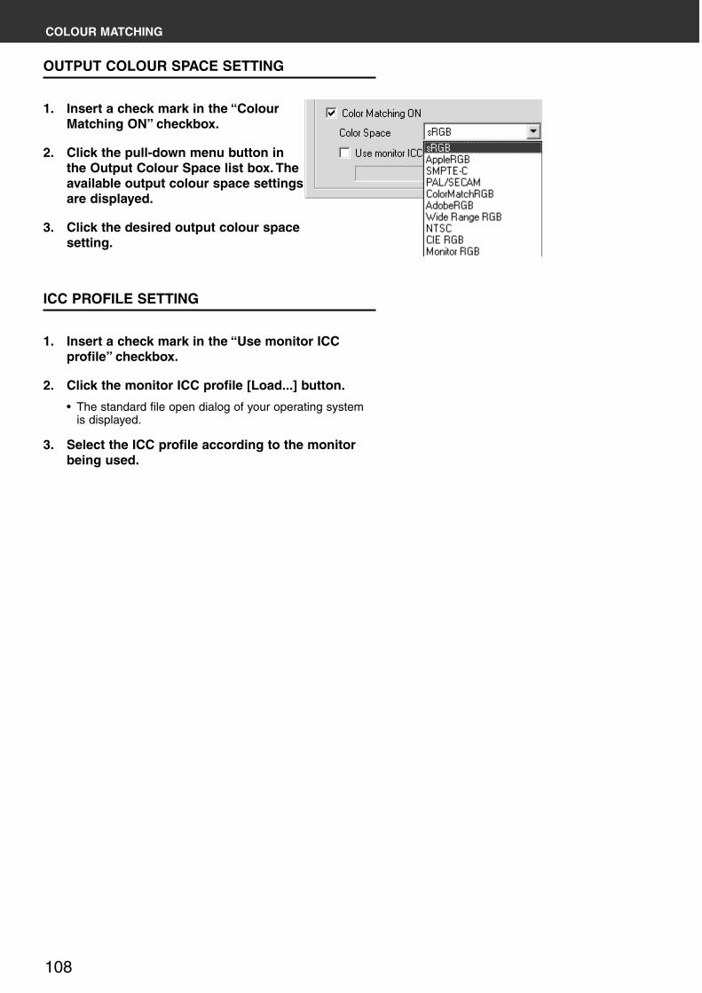
108
COLOUR MATCHING
OUTPUT COLOUR SPACE SETTING
1. Insert a check mark in the “ColourMatching ON” checkbox.
2. Click the pull-down menu button inthe Output Colour Space list box. Theavailable output colour space settingsare displayed.
3. Click the desired output colour spacesetting.
ICC PROFILE SETTING
1. Insert a check mark in the “Use monitor ICCprofile” checkbox.
2. Click the monitor ICC profile [Load...] button.
• The standard file open dialog of your operating systemis displayed.
3. Select the ICC profile according to the monitorbeing used.

DiMAGE Scan Multi PRO 109
The supplied CD-ROM includes the ICC profile for other colour matching tool. (Thedirectory or file name for Windows or Macintosh is shown respectively.) This ICC profileis used for images (except the images with 16-bit linear) of the positive film that have
been scanned with the Colour Matching function OFF setting.
COLOUR MATCHING
Regarding the “Output Colour Space” and the “Monitor ICC Profile” setting, the combinationwith respect to the application, the recommended preference setting is as follows.
When an application with Monitor Correction Display function(*1) (such as the AdobePhotoshop Ver. 5 to 6) is being used with the Monitor Correction Display function ONOutput Colour Space: Optional output colour space can be selected
(select the same colour space as set in the application)ICC Profile(*2): Use
When an application without Monitor Correction Display function(*1) is being usedIt is possible to match it to your monitor’s own colour space and not the optional output colourspace.Output Colour Space: Select [Monitor RGB]ICC Profile(*2): Use
* When using the Windows Adobe Photoshop 4.0.1, the above setting is only effective if the monitor gamma ofthe application is set to 2.2.
*1: A function to correct the characteristics of the monitor and display the images appropriately.*2: This sets the ICC profile of your monitor.

110
SCAN JOB FILE LIST — 35 mm
�������� ���� � �������������� ����������� ���� ���� ���������� �������� ������ ���� ������� � ������
! " ! " ! "
#$%% &'(%$� )*(%)� '%%$ #')$
+(#,%� %(-$*�
.�/��0� .�/��0� +)%% &%% #%% ��1�0 +'*) ++$) �22 +'*) ++$) �22 +'*) ++$)
��0�������3������ 4#2�00 #$%% ,%% $%% &*(&$ )*(%) �22 )$& )%%(+*) �� ,,$* #')$
4#"�0/ &**% ,%% *-+ &*(*& )*(%# �22 )+% +#$ �� #-,% &#-,
4#5����� )*+$ ,%% #+- &*(&) )*(%, �22 +#$ +%* �� &#-, )#$%
������2�00 #$%% ,%% $%% ���6 +(), %(-- �22 +%(+ '($$ �� ,%,% #')$
������"�0/ &#-# ,%% *$) ���6 +(#, %(-# �22 $(* *(#* �� *+%% &)'%
������5����� )*$- ,%% #&+ ���6 +(), %(-- �22 *(#* #()* �� &)'% )**%
36����������7� 4&2�00 #'#- #%% ++$' &*(&$ )*(%) �22 #)% )-' �� ,,+# #,''
4#2�00 &&*$ #%% $&- &*(# )*(%& �22 )-' )+% �� #,'' &&%'
4*2�00 )&,, #%% *-+ &*(*& )*(%# �22 )+% +#$ �� &&%' )&&%
������2�00 &#*) #%% $,& ���6 +(), %(-- �22 +%(- $(* �� #&,% &#%%
������"�0/ )&)- #%% *$) ���6 +(#, %(-# �22 $(* *(#* �� &#%% )+$%
������5����� +'), #%% #&+ ���6 +(), %(-- �22 *(#* #()* �� )+$% +'%%
$1+% &)#- #%% $+) ���6 +()& %(-- �22 +% $ �� #%%% &)%%
++1+# ##,% #%% +++* &+(-& )*(%) �22 &*, )'- �� *,%, #&-&
+%1+) #%,+ #%% +%+* &%(%* )*(%) �22 &%* )*# �� #$%& #%%%
)� )%&+ #%% *%' &*(++ )*(%* �22 +'$ +)' �� )$%& )%%%
3������8#1, +,## #%% #++ ���6 +(#, %(-' �22 , # �� )#%% +,%%
���9���: �����; &-#* &%% +&+* &,('& )*(%) �22 #$& &)- �� *'%# &$$*
.��9��3������ 4&2�00 &*,+ &%% ++$' &*(&$ )*(%) �22 #)% )-' �� #-,% &*%'
4#2�00 )*+$ &%% $&- &*(# )*(%& �22 )-' )+% �� &*%' )#$%
4#"�0/ +''* &%% *-+ &*(*& )*(%# �22 )+% +#$ �� )#$% +'#$
4#5������ +)*- &%% #+- &*(&) )*(%, �22 +#$ +%* �� +'#$ +)#%
������2�00 )*$- &%% $,& ���6 +(), %(-- �22 +%(- $(* �� &)'% )**%
������"�0/ +'#' &%% *$) ���6 +(#, %(-# �22 $(* *(#* �� )**% +,&*
������5����� +)-* &%% #&+ ���6 +(), %(-- �22 *(#* #()* �� +,&* +)'*
36���#1, +)+# &%% #%# &'(+& )#('* �22 +*% +%% �� +''+ ++$+
36���&1* +%,$ &%% &*, &*(,' )* �22 +)' $- �� +*%% +%*+
!�3��� +)#%1$&, $*% ') ++$% ��1�0 +)#% $&, �22 +)#% $&, �� +)#% $&,
+++)1'*% ',) ') +%*$ ��1�0 +++) '*% �22 +++) '*% �� +++) '*%
-$#1,,& ,'# ') -&, ��1�0 -$# ,,& �22 -$# ,,& �� -$# ,,&
'-)1*&# *#& ') '*# ��1�0 '-) *&# �22 '-) *&# �� '-) *&#
',%1*+) *)+ ') ')& ��1�0 ',% *+) �22 ',% *+) �� ',% *+)
,%%1#%# #++ ') *'% ��1�0 ,%% #%# �22 ,%% #%# �� ,%% #%#
&)%1)#% &%% ') #+, ��1�0 &)% )#% �22 &)% )#% �� &)% )#%
36����. 36����.)%#$1&%') )+%* &%% '%+ ��1�0 &%') )%#$ �22 &%') )%#$ �� &%') )%#$
36����.+%)#1+*&, +%*& &%% &*+ ��1�0 +*&, +%)# �22 +*&, +%)# �� +*&, +%)#
36����.*+)1',$ *)' &%% +'* ��1�0 ',$ *+) �22 ',$ *+) �� ',$ *+)
������ +-)%1+)%% +&+, ') +$)' ��1�0 +-)% +)%% �22 +-)% +)%% �� +-)% +)%%
+,%%1+)%% +)+- ') +,-& ��1�0 +,%% +)%% �22 +,%% +)%% �� +,%% +)%%
+)$%1+%)# +%#% ') +### ��1�0 +)$% +%)# �22 +)$% +%)# �� +)$% +%)#
+)$%1-,% -'* ') +&*# ��1�0 +)$% -,% �22 +)$% -,% �� +)$% -,%
++*)1$'% $$# ') +))' ��1�0 ++*) $'% �22 ++*) $'% �� ++*) $'%
+%)#1',$ '$% ') +%$& ��1�0 +%)# ',$ �22 +%)# ',$ �� +%)# ',$
$&)1,)# $&' ') ++,) ��1�0 $&) $)# �22 $&) $)# �� $&) $)#
$%%1,%% ,+% ') $#' ��1�0 $%% ,%% �22 $%% ,%% �� $%% ,%%
,#%1#$% #$$ ') ,'' ��1�0 ,#% #$% �22 ,#% #$% �� ,#% #$%
.��� ��� 4#"�0/ #), ') *-+ &*(*& )*(%# �22 )+% +#$ �� *-* #+-
4#5����� &%) ') #+- &*(&) )*(%, �22 +#$ +%* �� #+- )-'
4#<��6�6 &%% ') #+, )*()# +'('- �22 +%* '# �� )-' )%-
������"�0/ #)% ') *$& ���6 +(#, %(-& �22 $(* *(#* �� ,+) &-)
������5����� &++ ') #&+ ���6 +(), %(-- �22 *(#* #()* �� &-) &%,
������<��6�6 &%% ') #+, ���6 +(%) %(,* �22 #()* )(') �� &%, +-*
2�0 �����8�� #= )$%, )#%% ++, ��1�0 #%-, )'&+ �22 #%-, )'&+ �� #%-, )'&+
)= +#%& )#%% *$ ��1�0 )%#$ +&,* �22 )%#$ +&,* �� )%#$ +&,*

DiMAGE Scan Multi PRO 111
SCAN JOB FILE LIST — 35 mm

112
SCAN JOB FILE LIST — 120/220 (6x4.5)
�������� ���� � �������������� ����������� ���� ���� ���������� �������� ������ ����� ������� � ������
! " ! " ! "
&)%% #)(,'� *,(*$� *&', '+)$
+(,$� )()&�
.�/��0� .�/��0� $%% &%% ),, ��1�0 +&## +'$) �22 +&## +'$) �22 +&## +'$)
��0�������3������ 4&2�00 ##*# ,%% '#) #%(%& *,(, �22 )-' #)% �� '%+* --)+
4#2�00 &+*% ,%% *)* #% *,(*' �22 )+% )-' �� #-,% '%+*
4#"�0/ )))' ,%% &'+ &-($- *,(, �22 +#$ )+% �� &#-, #-,%
4#5����� +*'% ,%% ),+ #%()& *,('+ �22 +%* +#$ �� )#$% &#-,
������2�00 &%&, ,%% *%, ���6 +(,$ )(+* �22 $(* +%(- �� *+%% ,*#%
������"�0/ ))-% ,%% &$+ ���6 +(#& )()& �22 *(#* $(* �� &)'% *+%%
������5����� +*+$ ,%% )*& ���6 +(,$ )(+* �22 #()* *(#* �� )**% &)'%
36����������7� 4&2�00 )-'% #%% '#) #%(%& *,(, �22 )-' #)% �� #,'' ,,+#
4#2�00 )+%% #%% *)* #% *,(*' �22 )+% )-' �� &&%' #,''
4*2�00 +#$* #%% &'+ &-($- *,(, �22 +#$ )+% �� )&&% &&%'
������2�00 )%)# #%% *%, ���6 +(,$ )(+* �22 $(* +%(- �� &#%% #&,%
������"�0/ +*)' #%% &$+ ���6 +(#& )()& �22 *(#* $(* �� )+$% &#%%
������5����� +%+) #%% )*& ���6 +(,$ )(+* �22 #()* *(#* �� +'%% )+$%
$1+% +-%* #%% #', ���6 +(,$ )(+ �22 $ +% �� &)%% #%%%
++1+# ),+* #%% ,*& #)('& *#(*) �22 )'- &*, �� #&-& *,%,
+%1+) )&$+ #%% *-* #)(,- *+(), �22 )*# &%* �� #%%% #$%&
)� +)*- #%% &+# &$()) *,(,- �22 +)% +'$ �� +$$- )$%&
3������8#1, +%'$ #%% ),- ���6 +(#- )()& �22 # , �� +,%% )#%%
���9���: �����; )*,+ &%% $*& &$(*' *,(,) �22 &)- #$& �� &$$* *'%#
.��9��3������ 4&2�00 )))' &%% '#) #%(%& *,(, �22 )-' #)% �� &*%' #-,%
4#2�00 +*'* &%% *)* #% *,(*' �22 )+% )-' �� )#$% &*%'
4#"�0/ +++# &%% &'+ &-($- *,(, �22 +#$ )+% �� +'#$ )#$%
4#5������ '$* &%% ),+ #%()& *,('+ �22 +%* +#$ �� +)#% +'#$
������2�00 +*+$ &%% *%, ���6 +(,$ )(+* �22 $(* +%(- �� )**% &)'%
������"�0/ ++#* &%% &$+ ���6 +(#& )()& �22 *(#* $(* �� +,&* )**%
������5����� '*- &%% )*& ���6 +(,$ )(+* �22 #()* *(#* �� +)'* +,&*
36���#1, '-, &%% ),* &'('# *,(, �22 +%% +*% �� ++$+ +''+
36���&1* ,'# &%% ))# &-('& *,(' �22 $- +)' �� +%*+ +*%%
!�3��� +)#%1-&* **' ') ''& ��1�0 -&* +)#% �22 -&* +)#% �� -&* +)#%
+++)1$&- *%% ') ,-# ��1�0 $&- +++) �22 $&- +++) �� $&- +++)
-$#1'#) ##) ') ,+& ��1�0 '#) -$# �22 '#) -$# �� '#) -$#
'-)1*-' &*, ') #-# ��1�0 *-' '-) �22 *-' '-) �� *-' '-)
',%1*'& &#) ') #'* ��1�0 *'& ',% �22 *'& ',% �� *'& ',%
,%%1#*) )'% ') &'* ��1�0 #*) ,%% �22 #*) ,%% �� #*) ,%%
&)%1)#% )%% ') )'' ��1�0 )#% &)% �22 )#% &)% �� )#% &)%
36����. 36����.)%#$1&%') +&$% &%% #,% ��1�0 )%#$ &%') �22 )%#$ &%') �� )%#$ &%')
36����.+%)#1+*&, ,-% &%% )&% ��1�0 +%)# +*&, �22 +%)# +*&, �� +%)# +*&,
36����.*+)1',$ &#* &%% ++* ��1�0 *+) ',$ �22 *+) ',$ �� *+) ',$
������ +-)%1+)%% $,) ') ++-' ��1�0 +)%% +-)% �22 +)%% +-)% �� +)%% +-)%
+,%%1+)%% '+- ') --$ ��1�0 +)%% +,%% �22 +)%% +,%% �� +)%% +,%%
+)$%1+%)# ,+% ') $#' ��1�0 +%)# +)$% �22 +%)# +)$% �� +%)# +)$%
+)$%1-,% *'* ') '-$ ��1�0 -,% +)$% �22 -,% +)$% �� -,% +)$%
++*)1$'% *+$ ') '+- ��1�0 $'% ++*) �22 $'% ++*) �� $'% ++*)
+%)#1',$ #,% ') ,&$ ��1�0 ',$ +%)# �22 ',$ +%)# �� ',$ +%)#
$&)1,)# &'# ') *+- ��1�0 ,)# $&) �22 ,)# $&) �� ,)# $&)
$%%1,%% &,% ') *%% ��1�0 ,%% $%% �22 ,%% $%% �� ,%% $%%
,#%1#$% )$$ ') #%% ��1�0 #$% ,#% �22 #$% ,#% �� #$% ,#%
.��� ��� 4#"�0/ ),$ ') &') &-('- *,(#* �22 +#$ )+% �� #+- *-*
4#5����� )%% ') )'' &'(-+ *&(#& �22 +%* +#$ �� )-' #+-
4#<��6�6 )%% ') )'' ),('+ &'(-+ �22 '# +%* �� )%- )-'
������"�0/ )'* ') &$+ ���6 +(#& )()& �22 *(#* $(* �� &-) ,+)
������5����� )%% ') )'' ���6 +(*& +(-' �22 #()* *(#* �� &%, &-)
������<��6�6 )%% ') )'' ���6 %(-$ +(*& �22 )(') #()* �� +-* &%,

DiMAGE Scan Multi PRO 113
SCAN JOB FILE LIST — 120/220 (6x4.5)

114
SCAN JOB FILE LIST — 120/220 (6x6)
�������� ���� � �������������� ����������� ���� ���� ���������� �������� ������ ���� ������� � ������
! " ! " ! "
&)%% *,(*$� *,(*$� '+)$ '+)$
)()&� )()&�
.�/��0� .�/��0� $%% &%% ),, ��1�0 +'$) +'$) �22 +'$) +'$) �22 +'$) +'$)
��0�������3������ 4&2�00 &+*% ,%% *)* *,(*' *,(*' �22 )-' )-' �� '%+* '%+*
4#2�00 )))' ,%% &'+ *,(, *,(, �22 )+% )+% �� #-,% #-,%
4#"�0/ +*'% ,%% ),+ *,('+ *,('+ �22 +#$ +#$ �� &#-, &#-,
4#5����� +++# ,%% +$* *,(', *,(', �22 +%* +%* �� )#$% )#$%
������2�00 ))-% ,%% &$+ ���6 )()& )()& �22 $(* $(* �� *+%% *+%%
������"�0/ +#,- ,%% )## ���6 )()& )()& �22 *(#* *(#* �� &)'% &)'%
������5����� ++#* ,%% +-% ���6 )()# )()# �22 #()* #()* �� )**% )**%
36����������7� 4&2�00 )+%% #%% *)* *,(*' *,(*' �22 )-' )-' �� #,'' #,''
4#2�00 +#$* #%% &'+ *,(, *,(, �22 )+% )+% �� &&%' &&%'
4*2�00 +%#' #%% ),+ *,('+ *,('+ �22 +#$ +#$ �� )&&% )&&%
������2�00 +*)' #%% &$+ ���6 )()& )()& �22 $(* $(* �� &#%% &#%%
������"�0/ -'- #%% )## ���6 )()& )()& �22 *(#* *(#* �� )+$% )+$%
������5����� ',# #%% +-+ ���6 )()& )()& �22 #()* #()* �� +'%% +'%%
$1+% +#&' #%% &*- ���6 )()& )()& �22 $ $ �� &)%% &)%%
+#1+' )*+' #%% ,)- *,(, *,(, �22 &*, &*, �� *,%, *,%,
++1+# +-'& #%% #-& *,(*- *,(*- �22 )'- )'- �� #&-& #&-&
+%1+) +'-, #%% ##- *,(*' *,(*' �22 )*# )*# �� #%%% #%%%
)� $-$ #%% ))# *,(' *,(' �22 +)' +)' �� )%%% )%%%
3������8#1, '+- #%% +'- ���6 )()& )()& �22 # # �� +,%% +,%%
���9���: �����; +'#* &%% *$+ *,(,& *,(,& �22 &)- &)- �� &$$* &$$*
.��9��3������ 4&2�00 +*'* &%% *)* *,(*' *,(*' �22 )-' )-' �� &*%' &*%'
4#2�00 +++# &%% &'+ *,(, *,(, �22 )+% )+% �� )#$% )#$%
4#"�0/ '$* &%% ),+ *,('+ *,('+ �22 +#$ +#$ �� +'#$ +'#$
4#5������ **' &%% +$* *,(', *,(', �22 +%* +%* �� +)#% +)#%
������2�00 ++#* &%% &$+ ���6 )()& )()& �22 $(* $(* �� )**% )**%
������"�0/ '&* &%% )#* ���6 )()) )()) �22 *(#* *(#* �� +,&* +,&*
������5����� *'& &%% +-+ ���6 )()& )()& �22 #()* #()* �� +)'* +)'*
36���#1, *&+ &%% +'' *,(* *,(* �22 +%% +%% �� ++$+ ++$+
36���&1* #') &%% +*' *,(,- *,(,- �22 $- $- �� +%*+ +%*+
!�3��� +)#%1+)#% **' ') ''& ��1�0 +)#% +)#% �22 +)#% +)#% �� +)#% +)#%
+++)1+++) *%% ') ,-# ��1�0 +++) +++) �22 +++) +++) �� +++) +++)
-$#1-$# ##) ') ,+& ��1�0 -$# -$# �22 -$# -$# �� -$# -$#
'-)1'-) &*, ') #-# ��1�0 '-) '-) �22 '-) '-) �� '-) '-)
',%1',% &#) ') #'* ��1�0 ',% ',% �22 ',% ',% �� ',% ',%
,%%1,%% )'% ') &'* ��1�0 ,%% ,%% �22 ,%% ,%% �� ,%% ,%%
&)%1)#% )%% ') )'' ��1�0 &)% )#% �22 &)% )#% �� &)% )#%
36����. 36����.)%#$1&%') +&$% &%% #,% ��1�0 &%') )%#$ �22 &%') )%#$ �� &%') )%#$
36����.+%)#1+*&, ,-% &%% )&% ��1�0 +*&, +%)# �22 +*&, +%)# �� +*&, +%)#
36����.*+)1',$ &#* &%% ++* ��1�0 ',$ *+) �22 ',$ *+) �� ',$ *+)
������ +-)%1+)%% $,) ') ++-' ��1�0 +-)% +)%% �22 +-)% +)%% �� +-)% +)%%
+,%%1+)%% '+- ') --$ ��1�0 +,%% +)%% �22 +,%% +)%% �� +,%% +)%%
+)$%1+%)# *'* ') '-$ ��1�0 +)$% +%)# �22 +)$% +%)# �� +)$% +%)#
+)$%1-,% *'* ') '-$ ��1�0 +)$% -,% �22 +)$% -,% �� +)$% -,%
++*)1$'% *+$ ') '+- ��1�0 ++*) $'% �22 ++*) $'% �� ++*) $'%
+%)#1',$ #,% ') ,&$ ��1�0 +%)# ',$ �22 +%)# ',$ �� +%)# ',$
$&)1,)# &'# ') *+- ��1�0 $&) ,)# �22 $&) ,)# �� $&) ,)#
$%%1,%% &,% ') *%% ��1�0 $%% ,%% �22 $%% ,%% �� $%% ,%%
,#%1#$% )$$ ') #%% ��1�0 ,#% #$% �22 ,#% #$% �� ,#% #$%
.��� ��� 4#"�0/ )%% ') )'' *&(#& *&(#& �22 +#$ +#$ �� #+- #+-
4#5����� )%% ') )'' &'(-+ &'(-+ �22 +%* +%* �� )-' )-'
4#<��6�6 )%% ') )'' ),('+ ),('+ �22 '# '# �� )%- )%-
������"�0/ )%% ') )'' ���6 +(-' +(-' �22 *(#* *(#* �� &-) &-)
������5����� )%% ') )'' ���6 +(*& +(*& �22 #()* #()* �� &%, &%,
������<��6�6 )%% ') )'' ���6 %(-' %(-' �22 )(,- )(,- �� +-& +-&

DiMAGE Scan Multi PRO 115
SCAN JOB FILE LIST — 120/220 (6x6)
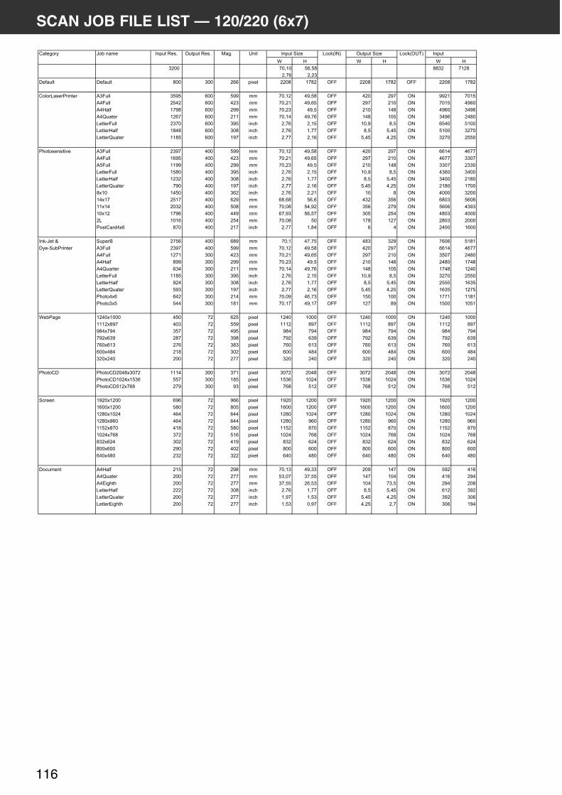
116
SCAN JOB FILE LIST — 120/220 (6x7)
�������� ���� � �������������� ����������� ���� ���� ���������� �������� ������ ���� ������� � ������
! " ! " ! "
&)%% '%(+%� *,(*$� $$&) '+)$
)(',� )()&�
.�/��0� .�/��0� $%% &%% ),, ��1�0 ))%$ +'$) �22 ))%$ +'$) �22 ))%$ +'$)
��0�������3������ 4&2�00 &*-* ,%% *-- '%(+) #-(*$ �22 #)% )-' �� --)+ '%+*
4#2�00 )*#) ,%% #)& '%()+ #-(,* �22 )-' )+% �� '%+* #-,%
4#"�0/ +'-$ ,%% )-- '%()& #-(* �22 )+% +#$ �� #-,% &#-,
4#5����� +),' ,%% )++ '%(+# #-(', �22 +#$ +%* �� &#-, )#$%
������2�00 )&'% ,%% &-* ���6 )(', )(+* �22 +%(- $(* �� ,*#% *+%%
������"�0/ +$#$ ,%% &%$ ���6 )(', +('' �22 $(* *(#* �� *+%% &)'%
������5����� ++$* ,%% +-' ���6 )('' )(+, �22 *(#* #()* �� &)'% )**%
36����������7� 4&2�00 )&-' #%% *-- '%(+) #-(*$ �22 #)% )-' �� ,,+# #,''
4#2�00 +,-* #%% #)& '%()+ #-(,* �22 )-' )+% �� #,'' &&%'
4*2�00 ++-- #%% )-- '%()& #-(* �22 )+% +#$ �� &&%' )&&%
������2�00 +*$% #%% &-* ���6 )(', )(+* �22 +%(- $(* �� #&,% &#%%
������"�0/ +)&) #%% &%$ ���6 )(', +('' �22 $(* *(#* �� &#%% )+$%
������5����� '-% #%% +-' ���6 )('' )(+, �22 *(#* #()* �� )+$% +'%%
$1+% +#*% #%% &,) ���6 )(', )()+ �22 +% $ �� #%%% &)%%
+#1+' )*+' #%% ,)- ,$(,$ *,(, �22 #&) &*, �� ,$%& *,%,
++1+# )%&) #%% *%$ '%(%$ *#(-) �22 &*, )'- �� *,%, #&-&
+%1+) +'-, #%% ##- ,'(-& *,(*' �22 &%* )*# �� #$%& #%%%
)� +%+, #%% )*# '%(%$ *% �22 +'$ +)' �� )$%& )%%%
3������8#1, $'% #%% )+' ���6 )('' +($# �22 , # �� )#%% +,%%
���9���: �����; )'*, #%% ,$- '%(+ #'('* �22 #$& &)- �� ',%, *+$+
.��9��3������ 4&2�00 )&-' #%% *-- '%(+) #-(*$ �22 #)% )-' �� ,,+# #,''
4#2�00 +)'+ &%% #)& '%()+ #-(,* �22 )-' )+% �� &*%' )#$%
4#"�0/ $-- &%% )-- '%()& #-(* �22 )+% +#$ �� )#$% +'#$
4#5������ ,&# &%% )++ '%(+# #-(', �22 +#$ +%* �� +'#$ +)#%
������2�00 ++$* &%% &-* ���6 )(', )(+* �22 +%(- $(* �� &)'% )**%
������"�0/ -)# &%% &%$ ���6 )(', +('' �22 $(* *(#* �� )**% +,&*
������5����� *-& &%% +-' ���6 )('' )(+, �22 *(#* #()* �� +,&* +)'*
36���#1, ,#) &%% )+# '%(%- #,('& �22 +*% +%% �� +''+ ++$+
36���&1* *## &%% +$+ '%(+' #-(+' �22 +)' $- �� +*%% +%*+
!�3��� +)#%1+%%% #*% ') ,)* ��1�0 +)#% +%%% �22 +)#% +%%% �� +)#% +%%%
+++)1$-' #%& ') **- ��1�0 +++) $-' �22 +++) $-' �� +++) $-'
-$#1'-# &*' ') #-* ��1�0 -$# '-# �22 -$# '-# �� -$# '-#
'-)1,&- )$' ') &-$ ��1�0 '-) ,&- �22 '-) ,&- �� '-) ,&-
',%1,+& )', ') &$& ��1�0 ',% ,+& �22 ',% ,+& �� ',% ,+&
,%%1#$# )+$ ') &%) ��1�0 ,%% #$# �22 ,%% #$# �� ,%% #$#
&)%1)#% )%% ') )'' ��1�0 &)% )#% �22 &)% )#% �� &)% )#%
36����. 36����.)%#$1&%') +++# &%% &'+ ��1�0 &%') )%#$ �22 &%') )%#$ �� &%') )%#$
36����.+%)#1+*&, **' &%% +$* ��1�0 +*&, +%)# �22 +*&, +%)# �� +*&, +%)#
36����.*+)1',$ )'- &%% -& ��1�0 ',$ *+) �22 ',$ *+) �� ',$ *+)
������ +-)%1+)%% ,-, ') -,, ��1�0 +-)% +)%% �22 +-)% +)%% �� +-)% +)%%
+,%%1+)%% *$% ') $%* ��1�0 +,%% +)%% �22 +,%% +)%% �� +,%% +)%%
+)$%1+%)# #,# ') ,## ��1�0 +)$% +%)# �22 +)$% +%)# �� +)$% +%)#
+)$%1-,% #,# ') ,## ��1�0 +)$% -,% �22 +)$% -,% �� +)$% -,%
++*)1$'% #+$ ') *$% ��1�0 ++*) $'% �22 ++*) $'% �� ++*) $'%
+%)#1',$ &') ') *+, ��1�0 +%)# ',$ �22 +%)# ',$ �� +%)# ',$
$&)1,)# &%) ') #+- ��1�0 $&) ,)# �22 $&) ,)# �� $&) ,)#
$%%1,%% )-% ') #%) ��1�0 $%% ,%% �22 $%% ,%% �� $%% ,%%
,#%1#$% )&) ') &)) ��1�0 ,#% #$% �22 ,#% #$% �� ,#% #$%
.��� ��� 4#"�0/ )+* ') )-$ '%(+& #-(&& �22 )%- +#' �� *-) #+,
4#5����� )%% ') )'' *&(%' &'(** �22 +#' +%# �� #+, )-#
4#<��6�6 )%% ') )'' &'(** ),(*& �22 +%# '&(* �� )-# )%$
������"�0/ ))) ') &%$ ���6 )(', +('' �22 $(* *(#* �� ,+) &-)
������5����� )%% ') )'' ���6 +(-' +(*& �22 *(#* #()* �� &-) &%,
������<��6�6 )%% ') )'' ���6 +(*& %(-' �22 #()* )(' �� &%, +-#

DiMAGE Scan Multi PRO 117
SCAN JOB FILE LIST — 120/220 (6x7)

118
SCAN JOB FILE LIST — 120/220 (6x8)
�������� ���� � �������������� ����������� ���� ���� ���������� �������� ������ ���� ������� � ������
! " ! " ! "
&)%% ''(+*� *,(*$� -')% '+)$
&(%#� )()&�
.�/��0� .�/��0� $%% &%% ),, ��1�0 )#&% +'$) �22 )#&% +'$) �22 )#&% +'$)
��0�������3������ 4&2�00 &)%% ,%% *&& ''() **(') �22 #++(#$ )-' �� -')% '%+*
4#2�00 )&+% ,%% &$* ''(+# *#(** �22 )-' )+% �� '%+* #-,%
4#"�0/ +,&& ,%% )') ''()+ *#(#+ �22 )+% +#$ �� #-,% &#-,
4#5����� ++*+ ,%% +-+ ''(#- *#(-' �22 +#$ +%* �� &#-, )#$%
������2�00 ))-% ,%% &$+ ���6 )($, )()& �22 +%(- $(* �� ,*#% *+%%
������"�0/ +,$% ,%% )$% ���6 &(%# +(-* �22 $(* *(#* �� *+%% &)'%
������5����� ++#* ,%% +-% ���6 )($' )()# �22 *(#* #()* �� &)'% )**%
36����������7� 4&2�00 )+'$ #%% *## ''()+ *#(, �22 #)% )-' �� ,,+# #,''
4#2�00 +*#% #%% &$* ''(+# *#(** �22 )-' )+% �� #,'' &&%'
4*2�00 +%$- #%% )') ''()+ *#(#+ �22 )+% +#$ �� &&%' )&&%
������2�00 +*)' #%% &$+ ���6 )($, )()& �22 +%(- $(* �� #&,% &#%%
������"�0/ ++)% #%% )$% ���6 &(%# +(-* �22 $(* *(#* �� &#%% )+$%
������5����� ',# #%% +-+ ���6 )($* )()& �22 *(#* #()* �� )+$% +'%%
$1+% +#&' #%% &*- ���6 )('- )()& �22 +% $ �� #%%% &)%%
+#1+' )*+' #%% ,)- ,$(,$ *,(, �22 #&) &*, �� ,$%& *,%,
++1+# +-'& #%% #-& ')()+ *,(*- �22 &*, )'- �� *,%, #&-&
+%1+) +'-, #%% ##- ,'(-& *,(*' �22 &%* )*# �� #$%& #%%%
)� -)& #%% )&% ''(&- **()) �22 +'$ +)' �� )$%& )%%%
3������8#1, '-+ #%% +-' ���6 &(%* )(%& �22 , # �� )#%% +,%%
���9���: �����; +$'$ &%% ,), ''(+, *)(*, �22 #$& &)- �� *'%# &$$*
.��9��3������ 4&2�00 +,&& &%% *## ''()+ *#(, �22 #)% )-' �� #-,% &*%'
4#2�00 ++** &%% &$* ''(+# *#(** �22 )-' )+% �� &*%' )#$%
4#"�0/ $+' &%% )') ''()+ *#(#+ �22 )+% +#$ �� )#$% +'#$
4#5������ *', &%% +-) ''(%$ *#(,- �22 +#$ +%* �� +'#$ +)#%
������2�00 ++#* &%% &$+ ���6 )($, )()& �22 +%(- $(* �� &)'% )**%
������"�0/ $#% &%% )$% ���6 &(%# +(-* �22 $(* *(#* �� )**% +,&*
������5����� *'& &%% +-+ ���6 )($* )()& �22 *(#* #()* �� +,&* +)'*
36���#1, *$# &%% +-# ''(&) *+(** �22 +*% +%% �� +''+ ++$+
36���&1* #-# &%% +,# ''(## *#()' �22 +)' $- �� +*%% +%*+
!�3��� +)#%1-%- #%- ') *,$ ��1�0 +)#% -%- �22 +)#% -%- �� +)#% -%-
+++)1$+* &,' ') *%- ��1�0 +++) $+* �22 +++) $+* �� +++) $+*
-$#1')+ &)# ') #*% ��1�0 -$# ')+ �22 -$# ')+ �� -$# ')+
'-)1*$% ),+ ') &,) ��1�0 '-) *$% �22 '-) *$% �� '-) *$%
',%1**' )*+ ') &#$ ��1�0 ',% **' �22 ',% **' �� ',% **'
,%%1##% )%% ') )'' ��1�0 ,%% ##% �22 ,%% ##% �� ,%% ##%
&)%1)#% )%% ') )'' ��1�0 &)% )#% �22 &)% )#% �� &)% )#%
36����. 36����.)%#$1&%') +%+) &%% &&' ��1�0 &%') )%#$ �22 &%') )%#$ �� &%') )%#$
36����.+%)#1+*&, *%, &%% +,$ ��1�0 +*&, +%)# �22 +*&, +%)# �� +*&, +%)#
36����.*+)1',$ )*& &%% $# ��1�0 ',$ *+) �22 ',$ *+) �� ',$ *+)
������ +-)%1+)%% ,&& ') $'- ��1�0 +-)% +)%% �22 +-)% +)%% �� +-)% +)%%
+,%%1+)%% *&- ') '#$ ��1�0 +,%% +)%% �22 +,%% +)%% �� +,%% +)%%
+)$%1+%)# #,% ') ,&$ ��1�0 +)$% +%)# �22 +)$% +%)# �� +)$% +%)#
+)$%1-,% #&+ ') *-$ ��1�0 +)$% -,% �22 +)$% -,% �� +)$% -,%
++*)1$'% &-+ ') *#& ��1�0 ++*) $'% �22 ++*) $'% �� ++*) $'%
+%)#1',$ &#* ') #'- ��1�0 +%)# ',$ �22 +%)# ',$ �� +%)# ',$
$&)1,)# )$+ ') &-% ��1�0 $&) ,)# �22 $&) ,)# �� $&) ,)#
$%%1,%% )'% ') &'* ��1�0 $%% ,%% �22 $%% ,%% �� $%% ,%%
,#%1#$% )+, ') &%% ��1�0 ,#% #$% �22 ,#% #$% �� ,#% #$%
.��� ��� 4#"�0/ )%% ') )'' '*($+ *&(#& �22 )+% +#$ �� *-* #+-
4#5����� )%% ') )'' *&(#& &'(-+ �22 +#$ +%* �� #+- )-'
4#<��6�6 )%% ') )'' &'(-+ ),('+ �22 +%* '# �� )-' )%-
������"�0/ )%) ') )$% ���6 &(%# +(-* �22 $(* *(#* �� ,+) &-)
������5����� )%% ') )'' ���6 +(-' +(*& �22 *(#* #()* �� &-) &%,
������<��6�6 )%% ') )'' ���6 +(*& %(-$ �22 #()* )(') �� &%, +-*

DiMAGE Scan Multi PRO 119
SCAN JOB FILE LIST — 120/220 (6x8)

120
SCAN JOB FILE LIST — 120/220 (6x9)
�������� ���� � �������������� ����������� ���� ���� ���������� �������� ������ ����� ������� � ������
! " ! " ! "
&)%% $&($)� *,(*$� +%*,% '+)$
&(&%� )()&�
.�/��0� .�/��0� $%% &%% ),, ��1�0 ),#% +'$) �22 ),#% +'$) �22 ),#% +'$)
��0�������3������ 4&2�00 &+*% ,%% *)* $% *,(*' �22 #)% )-' �� --)+ '%+*
4#2�00 )))' ,%% &'+ $%(%* *,(, �22 )-' )+% �� '%+* #-,%
4#"�0/ +*'% ,%% ),+ $%(#, *,('+ �22 )+% +#$ �� #-,% &#-,
4#5����� +++# ,%% +$* $% *,(', �22 +#$ +%* �� &#-, )#$%
������2�00 ))-% ,%% &$+ ���6 )($, )()& �22 +%(- $(* �� ,*#% *+%%
������"�0/ +*#, ,%% )*' ���6 &(&+ )(+) �22 $(* *(#* �� *+%% &)'%
������5����� ++#* ,%% +-% ���6 )($' )()# �22 *(#* #()* �� &)'% )**%
36����������7� 4&2�00 )+%% #%% *)* $% *,(*' �22 #)% )-' �� ,,+# #,''
4#2�00 +#$* #%% &'+ $%(%* *,(, �22 )-' )+% �� #,'' &&%'
4*2�00 +%#' #%% ),+ $%(#, *,('+ �22 )+% +#$ �� &&%' )&&%
������2�00 +*)' #%% &$+ ���6 )($, )()& �22 +%(- $(* �� #&,% &#%%
������"�0/ +%&+ #%% )*' ���6 &(&+ )(+) �22 $(* *(#* �� &#%% )+$%
������5����� ',# #%% +-+ ���6 )($* )()& �22 *(#* #()* �� )+$% +'%%
$1+% +#&' #%% &*- ���6 )('- )()& �22 +% $ �� #%%% &)%%
+#1+' )*+' #%% ,)- ,$(,$ *,(, �22 #&) &*, �� ,$%& *,%,
++1+# +-'& #%% #-& ')()+ *,(*- �22 &*, )'- �� *,%, #&-&
+%1+) +'-, #%% ##- ,'(-& *,(*' �22 &%* )*# �� #$%& #%%%
)� $-$ #%% ))# '-(#, *,(' �22 +'$ +)' �� )$%& )%%%
3������8#1, ')$ #%% +$) ���6 &(& )() �22 , # �� )#%% +,%%
���9���: �����; +'#* &%% *$+ $&(+& *,(,& �22 #$& &)- �� *'%# &$$*
.��9��3������ 4&2�00 +*'* &%% *)* $% *,(*' �22 #)% )-' �� #-,% &*%'
4#2�00 +++# &%% &'+ $%(%* *,(, �22 )-' )+% �� &*%' )#$%
4#"�0/ '$* &%% ),+ $%(#, *,('+ �22 )+% +#$ �� )#$% +'#$
4#5������ **' &%% +$* $% *,(', �22 +#$ +%* �� +'#$ +)#%
������2�00 ++#* &%% &$+ ���6 )($, )()& �22 +%(- $(* �� &)'% )**%
������"�0/ ''& &%% )*' ���6 &(&+ )(+) �22 $(* *(#* �� )**% +,&*
������5����� *'& &%% +-+ ���6 )($* )()& �22 *(#* #()* �� +,&* +)'*
36���#1, *&' &%% +'- $&($ **($' �22 +*% +%% �� +''+ ++$+
36���&1* #') &%% +*' $%($- *,(,- �22 +)' $- �� +*%% +%*+
!�3��� +)#%1$&' &', &%% +)* ��1�0 +)#% $&' �22 +)#% $&' �� +)#% $&'
+++)1'*+ &&$ &%% ++) ��1�0 +++) '*+ �22 +++) '*+ �� +++) '*+
-$#1,,# )-- &%% -- ��1�0 -$# ,,# �22 -$# ,,# �� -$# ,,#
'-)1*&# )#% &%% $% ��1�0 '-) *&# �22 '-) *&# �� '-) *&#
',%1*+& )&+ &%% '' ��1�0 ',% *+& �22 ',% *+& �� ',% *+&
,%%1#%* )%% &%% ,, ��1�0 ,%% #%* �22 ,%% #%* �� ,%% #%*
&)%1)#% )%% &%% ,, ��1�0 &)% )#% �22 &)% )#% �� &)% )#%
36����. 36����.)%#$1&%') -&+ &%% &+% ��1�0 &%') )%#$ �22 &%') )%#$ �� &%') )%#$
36����.+%)#1+*&, #,, &%% +** ��1�0 +*&, +%)# �22 +*&, +%)# �� +*&, +%)#
36����.*+)1',$ )&& &%% '' ��1�0 ',$ *+) �22 ',$ *+) �� ',$ *+)
������ +-)%1+)%% *$) ') $%$ ��1�0 +-)% +)%% �22 +-)% +)%% �� +-)% +)%%
+,%%1+)%% *&- ') '#$ ��1�0 +,%% +)%% �22 +,%% +)%% �� +,%% +)%%
+)$%1+%)# #,% ') ,&$ ��1�0 +)$% +%)# �22 +)$% +%)# �� +)$% +%)#
+)$%1-,% #&+ ') *-$ ��1�0 +)$% -,% �22 +)$% -,% �� +)$% -,%
++*)1$'% &-+ ') *#& ��1�0 ++*) $'% �22 ++*) $'% �� ++*) $'%
+%)#1',$ &#* ') #'- ��1�0 +%)# ',$ �22 +%)# ',$ �� +%)# ',$
$&)1,)# )$+ ') &-% ��1�0 $&) ,)# �22 $&) ,)# �� $&) ,)#
$%%1,%% )'% ') &'* ��1�0 $%% ,%% �22 $%% ,%% �� $%% ,%%
,#%1#$% )+, ') &%% ��1�0 ,#% #$% �22 ,#% #$% �� ,#% #$%
.��� ��� 4#"�0/ )%% ') )'' '*($+ *&(#& �22 )+% +#$ �� *-* #+-
4#5����� )%% ') )'' *&(#& &'(-+ �22 +#$ +%* �� #+- )-'
4#<��6�6 )%% ') )'' &'(-+ ),('+ �22 +%* '# �� )-' )%-
������"�0/ )%% ') )'' ���6 &(%' +(-' �22 $(* *(#* �� ,+) &-)
������5����� )%% ') )'' ���6 +(-' +(*& �22 *(#* #()* �� &-) &%,
������<��6�6 )%% ') )'' ���6 +(*& %(-$ �22 #()* )(') �� &%, +-*

DiMAGE Scan Multi PRO 121
SCAN JOB FILE LIST — 120/220 (6x9)

122
SCAN JOB FILE LIST — MULTI FORMAT 35 mm
�������� ���� � �������������� ����������� ���� ���� ���������� �������� ������ ���� ������� � ������
! " ! " ! "
#$%% $&($)� )*(%)� +*$#% #')$
&(&%� %(--�
.�/��0� .�/��0� +)%% &%% #%% ��1�0 &-,% ++$) �22 &-,% ++$) �22 &-,% ++$)

DiMAGE Scan Multi PRO 123
SCAN JOB FILE LIST — MULTI FORMAT 35 mm

124
GLOSSARY
BRIGHTNESS The lightness or darkness of the image.
CHANNEL The component of an image. Your scanned image has three channels:red, green, and blue (RGB).
CONTRAST The gradation of shades in an image. A high contrast image has verydark areas and bright areas without many middle shades. A low contrastimage has many tones that are close to the same brightness. Lowcontrast images are often described as looking ‘flat’.
CROP To trim and delete the unwanted edges of the image.
DPI Dots (pixels) per inch.
EMULSION SIDE The side of the film coated with the photographic material.
GAMMA The contrast of only the middle tones.
HIGHLIGHTS The lighter areas of the image.
HISTOGRAM A graph showing the amount of each level of the 256 brightness levels.
IEEE 1394 Refer to the page 106.
INTERPOLATION A methord of adding new pixels to an image when resampling up.
JPEG The JPEG (Joint Photographic Experts Group) compression standard iscapable of producing a high compression ratio while maintaining imagequality. JPEG is a widely supported image file format.
MIDTONE The middle shades of an image, in between light and dark.
NEUTRAL Having no colour cast, such as black, white, or grey.
PICT (Macintosh operating system only) The PICT graphic file format uses alossless compression scheme and is compatible with many Macintoshapplications.
PIXEL Abbreviation for picture element. The dots that make up an electronicimage.
RESAMPLE To change the number of pixels in the image. If pixels are discardedwhen shrinking an image, it is called resampling down. If new pixels arecreated in an image, it is called resampling up (see page 89).
RESOLUTION The number of pixels in a given area of the image; such as pixels perinch or pixels per centimetre. High resolution is the term for an imagewith a lot of pixels in a given area. Low resolution means there are notmany pixels in a given area.

DiMAGE Scan Multi PRO 125
GLOSSARY
RGB Red, Green, and Blue. These are the colors of the three channels thatmake up the scanned image. Monitors use red, green, and bluephosphors to create the image you see on the screen.
SCSI (Ultra SCSI) Ultra SCSI (Fast-20) is one variation of the SCSI-3 standards now beingpromoted by ANSI (American National Standards Institute). SCSI-3refers to many variations including a parallel interface.
SHADOWS The dark areas of an image.
TIFF Tagged Image File Format (TIFF) files contain bit-mapped data. Inaddition to being a widely supported format, TIFF is able to handle thecolour palette needed for professional-quality images and graphics.
WINDOWS® BMP (Windows only) The BMP graphic file format is for bit-mapped images.BMP images are supported by the Paint accessory and can easily beopened on most PCs running Windows.

126
TROUBLE SHOOTING
• Load film into the film holder.
• Scanner door opened during setup. Closescanner door.
The computer will not start upafter connecting the scanner.
• Shut down the computer and all the devices inyour SCSI or IEEE 1394 chain, then check theSCSI or IEEE 1394 cables and AC power cord.
DS_Multi PRO does not appear inthe Import drop down list.
• Make sure the plug-in module has been placedin the correct folder. See page 26.
“Could not establish connectionwith scanner.”
• Indicator lamp is off - Turn the DiMAGE ScanMulti PRO on, then restart your system.
“Setting up now. Remove the filmholder.”
• Remove the film holder and click on [OK].
“Set film properly…”
Indicator lamp blinking rapidly(8Hz).
“Set 35mm film holder properly.” • Set the correct film type.
“Set Universal film holder properly.” • Set the correct film type.
“Could not recognise the film type.” • Set the film type manually.
“Insufficient Memory” • Increase the memory requirements for thehost application.
• If you have scanned multiple images, closeand relaunch the host application.
“Setting up now. Remove thefilm holder.” appears when thefilm holder is not loaded.
• Contact a Minolta Service Facility to changethe fluorescent lamp.
SYMPTOM or MESSAGE SOLUTION
Indicator lamp lights red. • Remove the optics locking screw on thebottom panel of the scanner.
• Insufficient amount of light.Contact a Minolta service Facility.
Scanning takes an extremelylong time.
• When an image of more than about 950 MB isscanned on Windows98 (SE) or Windows Me,the scanning speed may become extremelyslow. To avoid this, reduce the image size toabout 950 MB or smaller by lowering the inputresolution or changing the cropping area.
• With Macintosh, the scanning speed maybecome extremely slow when a large sizeimage is scanned using the Utility software. Toavoid this, use the Plug-in function.

DiMAGE Scan Multi PRO 127
USER TECHNICAL SUPPORT
Please contact your dealer for information regarding installation, SCSI or IEEE1394 interfacerecommendations, or application compatibility. If your dealer is unable to help you, contact anauthorized Minolta service center.
Please have the following information ready when calling Minolta Technical Support.
Make and Model of your computer:
Available application RAM:
Operating System version:
Other connected SCSI or IEEE1394 devices:
DS Multi PRO driver version number:
Symptoms:
Messages that appear on the screen when the problem occurs:
Frequency of occurrence:
Determining the version number of your driver software:
Place the pointer on the status window in the command window to displaythe version number.
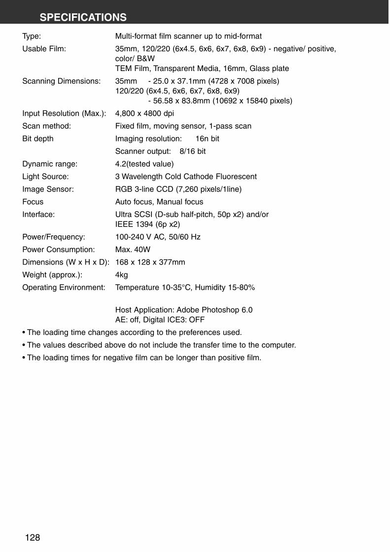
128
SPECIFICATIONS
Type: Multi-format film scanner up to mid-format
Usable Film: 35mm, 120/220 (6x4.5, 6x6, 6x7, 6x8, 6x9) - negative/ positive,color/ B&WTEM Film, Transparent Media, 16mm, Glass plate
Scanning Dimensions: 35mm - 25.0 x 37.1mm (4728 x 7008 pixels)120/220 (6x4.5, 6x6, 6x7, 6x8, 6x9)
- 56.58 x 83.8mm (10692 x 15840 pixels)
Input Resolution (Max.): 4,800 x 4800 dpi
Scan method: Fixed film, moving sensor, 1-pass scan
Bit depth Imaging resolution: 16n bit
Scanner output: 8/16 bit
Dynamic range: 4.2(tested value)
Light Source: 3 Wavelength Cold Cathode Fluorescent
Image Sensor: RGB 3-line CCD (7,260 pixels/1line)
Focus Auto focus, Manual focus
Interface: Ultra SCSI (D-sub half-pitch, 50p x2) and/orIEEE 1394 (6p x2)
Power/Frequency: 100-240 V AC, 50/60 Hz
Power Consumption: Max. 40W
Dimensions (W x H x D): 168 x 128 x 377mm
Weight (approx.): 4kg
Operating Environment: Temperature 10-35°C, Humidity 15-80%
Host Application: Adobe Photoshop 6.0AE: off, Digital ICE3: OFF
• The loading time changes according to the preferences used.
• The values described above do not include the transfer time to the computer.
• The loading times for negative film can be longer than positive film.

• Testing Conditions
IBM PC/AT CPU: Pentium IV 1.5GHz, RAM: 1GBOS: Windows 2000 ProfessionalInterface: IEEE1394:Adaptec AFW4300, Host Application: Adobe Photoshop 6.0AE: off; Digital ICE3: OFF
Macintosh CPU: PowerPC G4/533MHzRAM: 1.5GBOS: Mac OS 9.1Interface: FireWire
DiMAGE Scan Multi PRO 129
Index-Scan
Windows: 35mm Color Positive
6 frames/30 s.
Vorscan 9 s.
Scan 45 s.
Prescan
Windows: 120/220 (6x9) Color Positive
13 sec.
Scan 3 min 50 sec.
Index scan
Macintosh: 35mm Color Positive
6 frames/35sec.
Prescan 10 sec.
Scan 50 sec.
Prescan
Macintosh: 120/220 (6x9) Color Positive
15 sec.
Scan 4 min 10 sec.
Scan Times (approx.):
Specifications are based on the latest information available atthe time of printing and are subject to change without notice.