e. graitzer, a. cohen, v. dmitriev, i. balla, d. avizemer, d. beyer, k
TRANSCRIPT
Closed Loop Registration Control (RegC®) Using PROVE® as the Data Source for the RegC® Process
Erez Graitzer1; Avi Cohen1; Vladimir Dmitriev1; Itamar Balla1; Dan Avizemer1
Dirk Beyer2; Klaus Boehm2; Wolfgang Degel2
1. Carl Zeiss SMS Ltd Karmiel Israel 2. Carl Zeiss SMS GMBH Jena Germany
1. ABSTRACT At sub 4X nm nodes in memory and sub 3X nodes in logic devices mask registration (Reg) is becoming a significant yield limiting factor. This is especially true for Double Patterning Technologies (DPT) where mask to mask overlay on the wafer is heavily influenced by mask registration error. Getting advanced mask registration into specification is a challenge for all mask shops as the tight registration specs are driven by tight wafer overlay specs.
The first step in meeting the registration spec challenge in the mask shop is to be able to measure registration with the required specifications. With PROVE® Carl Zeiss SMS has recently introduced into the market a new registration and overlay metrology system which utilizes 193nm illumination for high resolution and a six axes controlled stage. The second step in meeting the registration spec challenge is to actively correct for intrinsic registration errors on the mask. For this Carl Zeiss SMS has developed the RegC® tool. The RegC® tool is based on writing strain zones with the help of an ultrashort pulse laser in the bulk of the mask. The strain zones induce deformations in the mask which practically push the misplaced features to a new location that after removing scale and orthogonality (S\O) correctable errors reflects a smaller residual registration error.
By combining the RegC® tool with data generated by PROVE® it is possible to close the loop on the registration control process in the mask shop without wafer print or mask re-write.
In this paper we report the demonstration results of a closed loop process between PROVE® and the RegC® tools.
Key words: Registration, Mask, Registration Control, RegC®, PROVE®, Overlay, Double Patterning, Image Placement
Invited Paper
Photomask and Next-Generation Lithography Mask Technology XIX, edited by Kokoro Kato,Proc. of SPIE Vol. 8441, 84410A · © 2012 SPIE · CCC code: 0277-786X/12/$18 · doi: 10.1117/12.976632
Proc. of SPIE Vol. 8441 84410A-1
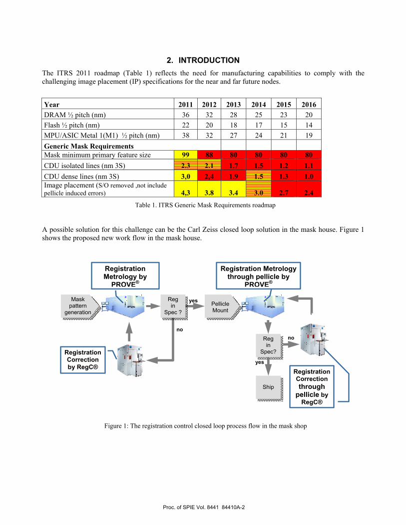
2. INTRODUCTION The ITRS 2011 roadmap (Table 1) reflects the need for manufacturing capabilities to comply with the challenging image placement (IP) specifications for the near and far future nodes.
Year 2011 2012 2013 2014 2015 2016 DRAM ½ pitch (nm) 36 32 28 25 23 20 Flash ½ pitch (nm) 22 20 18 17 15 14 MPU/ASIC Metal 1(M1) ½ pitch (nm) 38 32 27 24 21 19 Generic Mask Requirements Mask minimum primary feature size 99 88 80 80 80 80 CDU isolated lines (nm 3S) 2.3 2.1 1.7 1.5 1.2 1.1 CDU dense lines (nm 3S) 3,0 2,4 1.9 1.5 1.3 1.0 Image placement (S/O removed ,not include pellicle induced errors) 4,3 3.8 3.4 3.0 2.7 2.4
Table 1. ITRS Generic Mask Requirements roadmap
A possible solution for this challenge can be the Carl Zeiss closed loop solution in the mask house. Figure 1 shows the proposed new work flow in the mask house.
Figure 1: The registration control closed loop process flow in the mask shop
Registration Correction by RegC®
Mask pattern
generation
Registration Metrology by
PROVE®
Registration Metrology through pellicle by
PROVE®
Ship
yes
no
Reg in
Spec?
no
yes
Pellicle Mount
Reg in
Spec ?
Registration Correction through
pellicle by RegC®
Proc. of SPIE Vol. 8441 84410A-2
The closed loop solution works like this:
1. After completing the mask manufacturing process the mask is measured on the PROVE® tool. A Pre RegC® error map is prepared.
2. The Pre RegC® map is loaded to a special software (SW) that calculates a registration correction job
3. The registration correction job is loaded to the RegC® tool together with the mask and the RegC® process is run
4. The mask is then measured again on PROVE® which generates a Post RegC® map.
5. The improvement in registration in terms of residual registration error in nm and % improvement is calculated and reported.
As demonstrated in previous works [1,3,8], the RegC® process enables the mask maker to improve the mask registration by applying the RegC® process outside the exposure field. In this work we will demonstrate higher process efficiency by applying the RegC® over the mask exposure field in addition to the process on the periphery zone.
3. REGISTRATION BY PROVE® Since the successful market introduction of PROVE® [4,5,6] in 2010, the tool has been applied in particular for leading edge photomask registration and overlay measurement tasks. Figure 2 shows a PROVE® production tool in operation with all necessary components. During the design phase of the development project, special care was taken to reduce the environmental influences such as ambient air variations and vibrations. The metrology unit is located in an environmental chamber that precisely controls temperature and humidity specifications. The precision stage, which is fully controlled in all 6 degrees of freedom by laser interferometers, is situated on a frame resting on an actively controlled damping device. To minimize the effect of the remaining temperature, humidity, and barometric pressure variations, an on-line wavelength tracking device, the Etalon, is used to compensate for refractive index fluctuations of the air in real time. The masks are loaded onto the stage by a fully automated handling system, which can also rotate and flip the mask if required. A key component of PROVE® is the 193nm imaging optics that allow the resolution of production features even at the large working distances needed for different types of pellicles. For upcoming applications like extreme ultraviolet lithography (EUVL), the current 0.6 numerical aperture (NA) can be further increased to 0.8, which will improve the inherent high resolution of the tool by additional 30%. The two illumination paths of the tool offer measurements in transmission and reflection.
Proc. of SPIE Vol. 8441 84410A-3

Figure 2: PROVE® – Photomask Registration and OVErlay metrology system
Picture of the PROVE® tool in operation
The shorter wavelength automatically fulfills the accuracy requirement, as the 193nm metrology corresponds to the current state-of-the-art immersion scanners used for the contemporary technology nodes. Hence the material properties of the masks are accurately reflected in the measurements as in their later use in the fab.
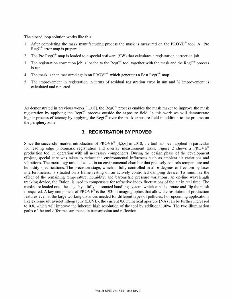
The tool inherent resolution power enables measurement on production features and mask to mask overlay qualification within the active area as demonstrated recently in [7]. However, in order to correct precisely for pattern placement errors by applying a RegC® process a reliable and stable metrology tool with excellent repeatability and accuracy is required. As a reference, Figure 3 and 4 display the short term repeatability as well as the nominal accuracy of the measurement tool which was used for this work.
Figure 3: Short-term repeatability performance over 20 loops measured on a CoG mask
The maximum 3sigma is 0.45 nm for the x-direction and 0.43 nm for the y-direction.
Proc. of SPIE Vol. 8441 84410A-4
Figure 4: Nominal accuracy performance over 10 loops@4 orientations (0°, 90°, 180°, 270°) measured on a CoG mask. The maximum 3sigma (confidence limit evaluation) is 0.97 nm for the x-direction and
0.87 nm for the y-direction.
4. THE REGISTRATION CONTROL (RegC®) PRINCIPLES Carl Zeiss SMS has developed a new technology and manufacturing tool named RegC® (figure 5) that enables the user (mask shop) to correct registration errors and improve image placement of a manufactured mask. The process is an extension of the CDC technology that uses a femto laser to write pixels inside the mask fused silica bulk. The RegC® tool writes special pixels so-called RegC® elements (deformation elements) in the bulk material of the mask which can affect the image placement location (mask registration)
In previous works [1,3,8] a detailed explanation of the RegC process concept was explained. Intravolume laser writing at certain conditions causes a predictable deformation element (RegC® element) in the fused silica (FS) material. This deformation is predicted and can be described by a physical mathematical model that represents the deformation caused by the RegC® element.
The deformed zone has a slightly different morphological structure with a slightly less dense packing, or lower density. The zone with lower density expands and pushes away the adjacent atoms and thus deforms the whole bulk of the FS piece.
A special model that was developed to describe the cumulative effect of a multitude of pixels on the FS substrate takes into account the physical properties of fused silica such as its Young Modulus, its Poisson ratio etc. This model has been verified experimentally [1,3,8].
Proc. of SPIE Vol. 8441 84410A-5

Figure 5: RegC® Registration Control tool
The direction of the deformation is controlled by applying different pixels having different deformation properties. The deformation properties of a given pixel such as magnitude and direction are described by its "signature" thus a specific mode of writing is described by the "mode signature" (MS) (for example an "X mode" represents a deformation along the X axis and is described by the X "mode signature"). When the registration control job is being calculated the algorithm computes where and in what density each type of RegC pixels should be written. For example a registration error in X direction will be corrected by X mode type of pixels. While solving a registration problem the model uses several modes in order to optimize the best possible solution for the specific registration problem. Typically X and Y modes which are orthogonal to each other will be used but other modes such as 45° and 135° may also be used if required.
The RegC tool is equipped with an in situ metrology system that can measure and quantify the pixel deformation properties using a fused silica blank. It reports the mode signature (MS) parameters. There is no need for external calibration using expensive registration metrology tools and patterned masks.
The RegC® model works in conjunction with the scanner abilities to remove systematic scaling and orthogonality errors, both of linear and higher orders, so that the RegC® has to remove only the errors which cannot be corrected by the scanner. In other words the RegC® process removes the scanner uncorrectable systematic residuals.
Proc. of SPIE Vol. 8441 84410A-6

5. EXPERIMENTAL RESULTS In this work we used the Carl Zeiss RegC® and PROVE® demo tools. In addition a dedicated mask was built for this test. This mask was manufactured by a laser writer and contains a relatively large registration error. Figure 6 shows the registration error of this mask as measured by the PROVE® tool on an array of 15x15 registration targets evenly distributed over the whole mask area .Table 1 show the statistics summary of raw and S/O residuals. As can be seen the linear scale and ortho corrections by the scanner improves registration by approximately 25% in both axis.
Figure 6: Reg error raw (left image) and after linear scale and ortho removal (right image)
Table 2: Whole mask data statistics summary before RegC®
For the RegC job computation an area of 104 mm x 132 mm was selected that reflects a typical exposure field of 26 x 33 mm (wafer level). For this test we used only two orthogonal mode signatures (X & Y directions). Figure 7 shows the pixel density distribution for each mode as computed by the RegC SW .In this job we used the CDU neutral mode [3,8] of computation that insures no CD uniformity degradation.
Units X Y Raw Data 3S (left image) nm 29.19 35.41 Residual 3S -linear S/O Removed (right image) nm 22.03 26.82 Improvement % 25 24
Proc. of SPIE Vol. 8441 84410A-7

Figure 7: The pixel density distribution over the whole mask area. Figure 7a (left) shows the density applied X mode, 7b (center) shows the density in Y mode. The sum of the two modes is shown in 7c image (right).
Figure 8 shows the process results and Table 2 its statistics summary. As can be seen the registration error was improved by more than a factor of two in 3 sigma values from the level of 15nm(Y) - 20nm(X) to the level of 7-8nm in both axis and in more than a factor of three in max error values from 25nm(X)-20nm(Y) to ~7nm in both X&Y axes.
Figure 8: The registration error inside the exposure field before the RegC® process (left) and after the RegC® right
Table 3: The RegC process statistics summary
Units X(3S) Y(3S) X(Max) Y(Max) Before RegC process (after linear scale and Ortho removal )
nm 19.78 15.30 25.33 20.06
After RegC process nm 8.46 7.35 6.99 7.62 Improvement % 57 52 72 62
Pre RegC process Post RegC process
High pixel density
Low pixel density 104 x 132 frame
7c 7b 7a
Proc. of SPIE Vol. 8441 84410A-8

6. DISCUSSION & CONCLUSIONS In this work the closed loop concept was demonstrated, a registration test mask was measured by the Carl Zeiss registration metrology PROVE® tool and this data was used as input to the RegC tool. The RegC® tool corrected this mask registration error and more then 50% improvement was demonstrated .The closed loop between the registration measurement tool PROVE® and the registration correction tool RegC® represents a powerful method to achieve critical registration specifications as needed for double patterning schemes. Since both tools can measure and process the mask with pellicle on they can be used in the wafer fab and correct for pellicle effects as well. In future work we plan show the show:
1. Mask to mask overlay control between layers 2. Double and multiple patterning overlay control in the same layer 3. Wafer overlay control for mix and match 193 to EUV
7. REFERENCES [1] E. Graitzer, G. Antesberger, et al., “Correcting Image Placement Error Using Registration Control (RegC®) Technology”, Proc. SPIE 7973, 797312 (2011).
[2] Schultz et al, “Meeting overlay requirements for future technology nodes with in-die overlay metrology”, Proc. SPIE 6518, 65180E (2007).
[3] E. Graitzer , et al.,”RegC™: A new Registration Control process for Photomasks after Pattern Generation”, Proc. SPIE 8081, 80810V (2011).
[4] Klose, G., et al., “Photomask Registration and Overlay Metrology by means of 193 nm Optics”, Proceedings of SPIE Vol. 7122 (2008).
[5] Huebel, A., et al., “Calibration strategies for precision stages in state-of-the-art registration metrology”, Proceedings of SPIE, Vol. 7379 (2009).
[6] Beyer, D., et al., “PROVE, the next generation registration metrology tool, status report”, Proceedings of SPIE, Vol. 7748 (2010).
[7] Seidel, D., et al., “Correlation method based mask to mask overlay metrology for 32nm node and beyond”, Proceedings of SPIE, Vol. 7985, 79850E (2011).
[8] A. Cohen1, F. Lange et al.,”Correcting Image Placement Errors Using Registration Control (RegC) Technology Over The Photomask Periphery”.
Proc. of SPIE Vol. 8441 84410A-9