e ect - pustaka.unpad.ac.idpustaka.unpad.ac.id/wp-content/uploads/2018/09/abstrak-effect-of... · a...
TRANSCRIPT

Ee t of Surfa e Defe ts on Sputteringby Grazing Ion BombardmentDissertationYudi Rosandi
Vom Fa hberei h Physikder Te hnis hen Universität Kaiserslauternzur Verleihung des akademis hen GradesDoktor der Naturwissens haftengenehmigte DissertationBetreuer: Prof. Dr. Herbert M. UrbassekZweitguta hter: Prof. Dr. Thomas Mi hely
Datum der wissens haftli hen Ausspra he: 27.06.2008

ii

for Rozan and Arofa

iv

AbstractThe ee ts of surfa e defe ts on a sputtering experiment at grazing ion in i-den e are observed using mole ular dynami s simulations. In this sequen e ofsimulations a Pt(111) is hosen as the target rystallite surfa e and a 5 keVAr+ ion is used as the ion proje tile. The angle of in iden e of the ion is83 with respe t to the surfa e normal, ex ept for some simulation where theinuen e of the in iden e angle is observed.On a lean at terra e the damage reation starts at the angle of in iden eϑ of around 81. For ϑ larger than this value, no damage is produ ed. By hanging gradually the angle of in iden e and observing the sputter yield asa fun tion of angle, the hara teristi of surfa e hanneling is determinable.The hara teristi hanneling angle at around 73, with respe t to the surfa enormal, is determined. At larger angles the sputter yield is very small. Atsmaller angles the yield is extremely in reased towards the value of normalin iden e.At grazing in iden e of 83 the situation hanges drasti ally, if the surfa eis overed randomly with a overage Θ of adatoms. For 0.1 < Θ < 0.5,average sputter yields and damage of up to a value of 5 and 9, respe tively,are a hieved. For overages around Θ = 0.3 − 0.4, 50 adatoms are relo atedon the average on the surfa e, ae ting an area of around 1000 Å2. Thision-indu ed mobility promotes adatom lustering, whi h typi ally leads to arim-like stru ture around the ion impa t point.The presen e of isolated surfa e defe ts also hanges the at-terra e behav-ior. This phenomenon is investigated for the spe i ase of 5 keV Ar+ ions im-pinging at 83 towards the surfa e normal onto the Pt (111) surfa e. Mole ular-dynami s simulations allow to study the inuen e of isolated adatoms in detail.The s attering of the proje tile from the adatom an redire t the proje tile,or let the adatom re oil, su h that either of them deposits onsiderable energyin the target surfa e, leading to abundant damage produ tion and sputtering.Two distin t ollision zones are identied: (i) When the proje tile hits thesurfa e in front of the adatom, it may ollide with the adatom indire tly (af-ter being spe ularly ree ted o the surfa e); (ii) alternatively, it may hit theadatom dire tly. The results are quantied by measuring the zone of inuen e(∼= 13 Å2) around the adatom, into whi h the proje tile must hit in order to ollide with the adatom, and by the sputter ross-se tion of roughly 110 Å2.The data ompare well with the sputtering of an atomi ally rough surfa e.

vi Abstra tAn adatom luster has a similar ee t. Here the sputtering yield in reasesrather steeply with respe t to the ase of isolated adatom. The luster a tivatesee tively the indire t-hit zone and in reases the zone of inuen e to 161 Å2,for a luster ontaining 7 adatoms. Only the atoms sitting at the as endingstep edge of a luster ontribute to sputtering. This denotes that small lustersare more e ient than large ones for a onstant overage. The sputter yield isnot azimuth independent. The bombardment from [110] produ es about one-half of the sputter yield of the ion bombardment from [112] azimuth dire tion.The impa t of a 5 keV Ar+ ion at 83 in iden e angle towards the surfa enormal onto a stepped Pt(111) surfa e is also investigated. Here the proje tileimpinges with a [112 azimuth on a B-step. The hanneled traje tories belowthe upper terra e is hara terized in terms of the distribution of hannelinglengths and the energy loss of hanneled proje tiles. The inuen e of targettemperature is studied by simulating targets at 0 K and at 550 K. In this sim-ulation a good agreement with the experimental observation on the hannelinglength is met.Finally, the sputter yield of a surfa e step is investigated in two azimuthdire tions, the [112] azimuth orresponds to the B-step and the [110] orre-sponds to the Kink-step. The fa t that the terra e sputter yield is zero in thissituation, enables to observe the intera tion between the in oming ions andthe onsidered step dire tly. The mole ular dynami s simulations give atom-isti insight into step edge sputtering and its azimuth dependen e, both at 0 Kand also at 550 K. A strong dependen e of the step edge sputtering yield ontemperature is dis overed.
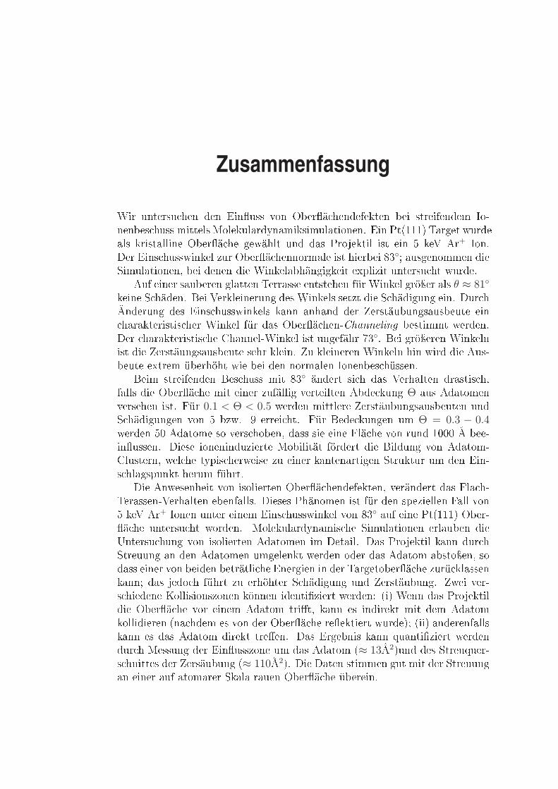
ZusammenfassungWir untersu hen den Einuss von Oberä hendefekten bei streifendem Io-nenbes huss mittels Molekulardynamiksimulationen. Ein Pt(111) Target wurdeals kristalline Oberä he gewählt und das Projektil ist ein 5 keV Ar+ Ion.Der Eins husswinkel zur Oberä hennormale ist hierbei 83; ausgenommen dieSimulationen, bei denen die Winkelabhängigkeit explizit untersu ht wurde.Auf einer sauberen glatten Terrasse entstehen für Winkel gröÿer als θ ≈ 81keine S häden. Bei Verkleinerung des Winkels setzt die S hädigung ein. Dur hÄnderung des Eins husswinkels kann anhand der Zerstäubungsausbeute ein harakteristis her Winkel für das Oberä hen-Channeling bestimmt werden.Der harakteristis he Channel-Winkel ist ungefähr 73. Bei gröÿeren Winkelnist die Zerstäungsausbeute sehr klein. Zu kleineren Winkeln hin wird die Aus-beute extrem überhöht wie bei den normalen Ionenbes hüssen.Beim streifenden Bes huss mit 83 ändert si h das Verhalten drastis h,falls die Oberä he mit einer zufällig verteilten Abde kung Θ aus Adatomenversehen ist. Für 0.1 < Θ < 0.5 werden mittlere Zerstäubungsausbeuten undS hädigungen von 5 bzw. 9 errei ht. Für Bede kungen um Θ = 0.3 − 0.4werden 50 Adatome so vers hoben, dass sie eine Flä he von rund 1000 Å bee-inussen. Diese ioneninduzierte Mobilität fördert die Bildung von Adatom-Clustern, wel he typis herweise zu einer kantenartigen Struktur um den Ein-s hlagspunkt herum führt.Die Anwesenheit von isolierten Oberä hendefekten, verändert das Fla h-Terassen-Verhalten ebenfalls. Dieses Phänomen ist für den speziellen Fall von5 keV Ar+ Ionen unter einem Eins husswinkel von 83 auf eine Pt(111) Ober-ä he untersu ht worden. Molekulardynamis he Simulationen erlauben dieUntersu hung von isolierten Adatomen im Detail. Das Projektil kann dur hStreuung an den Adatomen umgelenkt werden oder das Adatom abstoÿen, sodass einer von beiden beträtli he Energien in der Targetoberä he zurü klassenkann; das jedo h führt zu erhöhter S hädigung und Zerstäubung. Zwei ver-s hiedene Kollisionszonen können identiziert werden: (i) Wenn das Projektildie Oberä he vor einem Adatom trit, kann es indirekt mit dem Adatomkollidieren (na hdem es von der Oberä he reektiert wurde); (ii) anderenfallskann es das Adatom direkt treen. Das Ergebnis kann quantiziert werdendur h Messung der Einusszone um das Adatom (≈ 13Å2)und des Streuquer-s hnittes der Zersäubung (≈ 110Å2). Die Daten stimmen gut mit der Streuungan einer auf atomarer Skala rauen Oberä he überein.

viii ZusammenfassungDer Adatom-Cluster hat eine ähnli he Auswirkung. Hier steigt die Zer-stäubungsausbeute im Verglei h zum isolierten Adatom drastis h an. DerCluster aktiviert eektiv die indirekte Stoÿzone und vergröÿert damit die Ein-usszone auf 161Å2 (für einen Cluster mit 7 Adatomen). Nur Atome an derStufene ke des Clusters tragen zur Zerstäubung bei. Das bedeutet, dass kleineCluster eektiver sind, als groÿe bei glei her Bede kung. Die Zerstäbungsaus-beute ist zu dem azimutabhängig. Der Bes huss aus [110] ergibt eine nur halbso groÿe Zerstäubungsausbeute, als jener aus [112].Der Eins hlag von einem 5keV Ar Atom bei einem Eins hlagswinkel von83 auf eine Pt(111) Oberä he mit einer Stufe wurde ebenfalls untersu ht.Hier kommt das Projektil aus der[112] Ri htung auf eine B-Stufe auf. DasChanneling der Teil hen unter der obersten Terasse ist harakterisiert dur hdie Verteilung der Channel-längen und dem Energieverlust. Ein Einuss derTargettemperatur wurde für ein Substrat bei 0 K und 550 K untersu ht. Einegute Übereinstimmung der Channel-längen mit Experiment konnte hier erre-i ht werden.S hlieÿli h wurde die Zerstäubungsausbeute einer Oberä he mit Stufe inzwei azimutale Ri htungen untersu ht. Dabei entspri ht [112] einer B Stufeund [110] einer Kink Stufe. Die Tatsa he, dass die Terassen-Zerstäubungs-ausbeute hier Null ist, erlaubt die direkte Beoba htung der We hselwirkungzwis hen den einfallenden Ionen und der betra hteten Stufe. Die Molekular-dynamiksimulationen erlauben so einen atomaren Einbli k in die Zerstäubungan einer Stufe und ihre Ri htungsabhängigkeit. Au h diese Untersu hungwurde für 0 K und 550 K dur hgeführt. Eine starke Abhängigkeit der Zer-stäubungsausbeute von der Temperatur wurde hier beoba htet.

Contents
Title page iAbstra t vZusammenfassung viiContents ixList of gures xiiList of tables xixNomen lature xxi1 Introdu tion 12 Ion Surfa e Intera tions 52.1 Introdu tion . . . . . . . . . . . . . . . . . . . . . . . . . . . . . 52.2 Interatomi potential . . . . . . . . . . . . . . . . . . . . . . . . 52.2.1 Pair intera tion . . . . . . . . . . . . . . . . . . . . . . . 62.2.2 Many body intera tion . . . . . . . . . . . . . . . . . . . 92.2.3 Potential model for sputtering . . . . . . . . . . . . . . . 122.3 Atoms at Pt(111) surfa e . . . . . . . . . . . . . . . . . . . . . . 142.3.1 Surfa e geometry . . . . . . . . . . . . . . . . . . . . . . 162.3.2 Physi al behavior of surfa e defe ts . . . . . . . . . . . . 162.4 Ion surfa e hanneling . . . . . . . . . . . . . . . . . . . . . . . 192.4.1 Traje tory lassi ation . . . . . . . . . . . . . . . . . . 202.4.2 Continuum theory approximation . . . . . . . . . . . . . 213 Ion Surfa e Intera tion using Mole ular Dynami s Simulation 273.1 Introdu tion . . . . . . . . . . . . . . . . . . . . . . . . . . . . . 273.2 Algorithms and Tools . . . . . . . . . . . . . . . . . . . . . . . . 273.2.1 A glan e at mole ular-dynami s simulation . . . . . . . . 273.2.2 Controlling temperature . . . . . . . . . . . . . . . . . . 303.2.3 Sputtering and adatom dete tor . . . . . . . . . . . . . . 30
x CONTENTS3.3 Probing the surfa e . . . . . . . . . . . . . . . . . . . . . . . . . 323.3.1 Shadowing, blo king and hanneling traje tories . . . . . 323.3.2 Surfa e orrugation . . . . . . . . . . . . . . . . . . . . . 334 Grazing in iden e impa t of ions on an adatom- overed sur-fa e 374.1 Introdu tion . . . . . . . . . . . . . . . . . . . . . . . . . . . . . 374.2 Simulations method . . . . . . . . . . . . . . . . . . . . . . . . . 384.3 Results . . . . . . . . . . . . . . . . . . . . . . . . . . . . . . . . 394.3.1 Adatom mobility . . . . . . . . . . . . . . . . . . . . . . 394.3.2 Dependen e of damage and sputtering on overage . . . 424.3.3 Flu tuations . . . . . . . . . . . . . . . . . . . . . . . . . 444.4 Con lusions . . . . . . . . . . . . . . . . . . . . . . . . . . . . . 445 Inuen e of Single Adatom on Sputtering at Grazing In i-den e 475.1 Introdu tion . . . . . . . . . . . . . . . . . . . . . . . . . . . . . 475.2 Method . . . . . . . . . . . . . . . . . . . . . . . . . . . . . . . 485.2.1 Simulation . . . . . . . . . . . . . . . . . . . . . . . . . . 485.2.2 Sputter ross se tion . . . . . . . . . . . . . . . . . . . . 505.3 Results . . . . . . . . . . . . . . . . . . . . . . . . . . . . . . . . 515.3.1 Fate of the proje tile . . . . . . . . . . . . . . . . . . . . 515.3.2 Fate of the adatom . . . . . . . . . . . . . . . . . . . . . 525.3.3 Fate of the target . . . . . . . . . . . . . . . . . . . . . . 545.3.4 Zone of inuen e . . . . . . . . . . . . . . . . . . . . . . 555.3.5 Feasibility of an experimental measurement . . . . . . . 575.4 Con lusions . . . . . . . . . . . . . . . . . . . . . . . . . . . . . 586 Sputtering of Adatom Cluster on Pt(111) Surfa e 616.1 Introdu tion . . . . . . . . . . . . . . . . . . . . . . . . . . . . . 616.2 Method . . . . . . . . . . . . . . . . . . . . . . . . . . . . . . . 626.2.1 Simulation . . . . . . . . . . . . . . . . . . . . . . . . . . 626.2.2 Sputter yield . . . . . . . . . . . . . . . . . . . . . . . . 636.2.3 Hypotheses . . . . . . . . . . . . . . . . . . . . . . . . . 646.3 Results . . . . . . . . . . . . . . . . . . . . . . . . . . . . . . . . 646.3.1 Fate of adatom lusters . . . . . . . . . . . . . . . . . . . 696.3.2 Azimuthal dependen e . . . . . . . . . . . . . . . . . . . 716.4 Con lusions . . . . . . . . . . . . . . . . . . . . . . . . . . . . . 727 Surfa e Channeling in Grazing In iden e Ion Bombardmentof a Stepped Surfa e 737.1 Introdu tion . . . . . . . . . . . . . . . . . . . . . . . . . . . . . 737.2 Simulation method . . . . . . . . . . . . . . . . . . . . . . . . . 737.3 Results . . . . . . . . . . . . . . . . . . . . . . . . . . . . . . . . 75

CONTENTS xi7.3.1 Channeling . . . . . . . . . . . . . . . . . . . . . . . . . 757.3.2 Cold target rystal . . . . . . . . . . . . . . . . . . . . . 767.3.3 Elevated temperature . . . . . . . . . . . . . . . . . . . . 797.3.4 Angular dependen e of sub-surfa e hanneling . . . . . . 817.4 Con lusions . . . . . . . . . . . . . . . . . . . . . . . . . . . . . 828 Step edge sputtering through grazing in iden e ions 838.1 Introdu tion . . . . . . . . . . . . . . . . . . . . . . . . . . . . . 838.2 Geometri al model . . . . . . . . . . . . . . . . . . . . . . . . . 838.3 Simulation method . . . . . . . . . . . . . . . . . . . . . . . . . 858.4 Results . . . . . . . . . . . . . . . . . . . . . . . . . . . . . . . . 868.4.1 Sputtering on at terra e . . . . . . . . . . . . . . . . . . 868.4.2 Step edge sputter yield . . . . . . . . . . . . . . . . . . . 868.4.3 Elevated temperature . . . . . . . . . . . . . . . . . . . . 928.4.4 Angular dependen e . . . . . . . . . . . . . . . . . . . . 928.5 Comparison to experiment . . . . . . . . . . . . . . . . . . . . . 938.6 Con lusions . . . . . . . . . . . . . . . . . . . . . . . . . . . . . 959 Summary 97A Quantitative omparison of ion impa t on va an y and adatom IB The ex ess yield of step edge sputtering IIIC SimGen/Obje tMD: A brief introdu tion VIIBibliography XIList of Publi ations XVIIA knowledgment XIXCurri ulum Vitae XXI

xii CONTENTS
List of Figures
1.1 The illustration of grazing ion indu ed surfa e pattern formationon metal surfa e. . . . . . . . . . . . . . . . . . . . . . . . . . . 22.1 S reening fun tions al ulated for Ar+ ion with Pt atom inter-a tion. . . . . . . . . . . . . . . . . . . . . . . . . . . . . . . . . 72.2 A plot of Lennard-Jones potential. . . . . . . . . . . . . . . . . 92.3 The illustration of density of states of (a) isolated atoms, (b)atoms ited at surfa e and ( ) in the bulk. EF is the Fermi energy. 112.4 Taxonomy of (111) surfa e defe ts. Blue: the (111) terra e, red:the upper terra e/step, and brown: adatoms. . . . . . . . . . . . 152.5 Geometri al illustration of the (111) surfa e. . . . . . . . . . . . 152.6 Obje t densities determined by STM. (from referen e [1) . . . . 172.7 The sket h of ball-model of atom motion about the step. . . . . 182.8 Channeling on a surfa e and in a sub-surfa e layer. The hollow ir les are surfa e atoms, and the shaded ones are bulk/sub-surfa e atoms. The bla k balls represent in oming ions. . . . . . 202.9 The illustration of yield on impa t of ion to a surfa e at tiltedin iden e angle. ϑc denotes the hara teristi angle in whi h hanneling totally stops. Angles are measured parallel to thesurfa e . . . . . . . . . . . . . . . . . . . . . . . . . . . . . . . . 202.10 The sket h of axial hanneling. . . . . . . . . . . . . . . . . . . 222.11 Axial hannels of Ar+ ion in two atomi string dire tions ina Platinum rystal. (a) [112] and (b) [110]. The strings arestret hed perpendi ular to the paper. The ontour lines of74 eV, denoted by the short-dash-dotted lines, orrespond tothe transverse energy of 5 keV Ar+ ion impinging with ϑ = 7to the Pt(111) surfa e. . . . . . . . . . . . . . . . . . . . . . . . 232.12 (a) The ZBL surfa e ontinuum potential. (b) The net potentialinside the surfa e hannel for Ar+ ion inside Pt(111) planar hannel. . . . . . . . . . . . . . . . . . . . . . . . . . . . . . . . 253.1 The ow hart of mole ular dynami s simulation using velo ityverlet integration. . . . . . . . . . . . . . . . . . . . . . . . . . . 29
xiv LIST OF FIGURES3.2 The denition of defe ts and the illustration of defe t dete tingme hanisms; (a) height dete tor, (b) luster dete tor. . . . . . . 313.3 Tree sear h algorithm. Blue arrow denotes a visit, and red onedenotes the return of a visit. The numbers at the blue arrowsare the sequen e of the visiting step. . . . . . . . . . . . . . . . 313.4 The shadow one for 5 keV Ar+ s attering to Pt atom. Thehollow balls are the next atoms in the orresponding row. Blue:〈110〉 and Bla k: 〈112〉 atomi row. . . . . . . . . . . . . . . . . 333.5 S attering of 5 keV Ar+ ion to a string of Platinum atoms at7 in iden e angle with respe t to the string axis. The inter-atomi distan es in both gures are (a) d〈112〉=4.8 Å, and (b)d〈110〉=2.78 Å. The string position is at the horizontal axis, y = 0 343.6 The plot of traje tories of 5 keV Ar+ ion impinging on a atsurfa e of Pt(111) at ϑ = 7, aligned with (a) 〈112〉 (b) 〈110〉dire tion. The blue line at 2.27Å denotes the position of nextatomi layer of the latti e (one monolayer, ZML). The distan ebetween interse tion points xc, measured geometri ally as xc =2 ∗ ZML/ tan(ϑ). . . . . . . . . . . . . . . . . . . . . . . . . . . 343.7 The distribution of ux inside the rainbow, shown in gure 3.6.b.The width of the rainbow at 2.27Å from the surfa e is 20.35Å. . 353.8 The minimum approa h distan e of 5 keV Ar+ ion traje toriesmoving at ϑ = 7 to the surfa e plane. The ions are moving in(a) [112] and (b) [110] dire tion. . . . . . . . . . . . . . . . . . . 354.1 Top view of the Pt (111) surfa e overed with Θ = 0.3 adatomsbefore (a) and after (b) the ion impa t. A produ tive event was hosen, with Ysp = 18 and Yad = 161; these values are onsid-erably above the average. The arrow denotes the ion impa tpoint. Atoms are olored a ording to the height above the atsurfa e (white). Note the lustering of the adatoms indu edby the ion impa t. In this ase also se ond-layer adatoms havebeen formed. ( ) Surfa e after ion impa t, as in subgure b: Allrelo ated adatoms have been olored bla k. . . . . . . . . . . . . 404.2 (a) Average number of relo ated adatoms, Nrel, due to glan ing-in iden e ion impa t on the Pt (111) surfa e. b: equivalentarea A inuen ed by adatom mobility, Eq. (4.1). ( ) Averagerelo ation length 〈r〉 of adatoms. . . . . . . . . . . . . . . . . . 414.3 Average numbers of adatoms produ ed, Yad, (a) and of sputteredatoms, Ysp, (b) due to glan ing-in iden e ion impa t on the Pt(111) surfa e. ( ) Fra tion p of sputtered atoms, whi h weresputtered from the adatom sites. . . . . . . . . . . . . . . . . . 434.4 (a)Frequen y distributions of the adatom produ tion and (b) ofthe sputtering. . . . . . . . . . . . . . . . . . . . . . . . . . . . . 44

LIST OF FIGURES xv5.1 (a) S hemati view of the Pt (111) surfa e, overed by an iso-lated adatom. The impa t azimuth [112 and the impa t linefor entral ollisions are indi ated. While the entire surfa e wasinvestigated for sputter events, ion impa ts on the `relevant im-pa t zone' were positioned on the ne grid shown. (b) Side viewof the Pt (111) surfa e indi ating the indire t-hit, the passing,and the dire t-hit zone. . . . . . . . . . . . . . . . . . . . . . . . 495.2 S attering angle ϑ of the proje tile as a fun tion of the impa tpoint x of the proje tile. ϑ is measured in the impa t plane withrespe t to the [112 dire tion along the surfa e. The regions offorward and ba kward s attering, and of implantation into thetarget are indi ated. The oordinate x measures the impa tpoint of the proje tile along this dire tion; x = 0 orrespondsto a dire t hit with the adatom. . . . . . . . . . . . . . . . . . . 525.3 S attering hara teristi s of the adatom as a fun tion of the im-pa t point x. (a) S attering angle ϑ in the impa t plane withrespe t to the [112 azimuth. (b) Kineti energy. ( ) Implanta-tion depth. (d) Migration distan e along the surfa e after 1 ps.Adatoms relo ated less than 0.5rNN, where rNN = 2.775 Å de-notes the nearest-neighbour distan e in Pt, may return to theiroriginal site. The arrows indi ate migration lengths > 8 Å. . . . 535.4 Sputter yield (a) and adatom yield (b) as a fun tion of theimpa t point x. . . . . . . . . . . . . . . . . . . . . . . . . . . . 545.5 Comparison of the present simulation data for sputtering of asurfa e overed with isolated adatoms (Θ ≪ 1) (full straightline) with those of a rough adatom- overed surfa e (0.1 ≤ Θ ≤0.9) (symbols, onne ted by line segments) from Ref. [2. . . . . 555.6 Top view of damage reated on the surfa e at 20 ps after ionimpa t. The ion is in ident from the left. The original lo ationof the adatom is indi ated by a bla k ir le. A ase of abundantdamage produ tion (x = −8 Å) was hosen. Colors denote theheight above the original surfa e plane. . . . . . . . . . . . . . . 565.7 Contour plot of sputter yield on the Pt (111) surfa e. The x-axis is dire ted along [112, the ion ight dire tion. The adatomwas originally at x = y = 0. Note the dierent axis s ales in x-and y-dire tion. The distin tion between the indire t-hit zone(x < −h tanϑ) and the dire t-hit zone (x > −h tanϑ) is learlyseen. . . . . . . . . . . . . . . . . . . . . . . . . . . . . . . . . . 565.8 Laterally averaged sputter yield as a fun tion of the impa tpoint x. . . . . . . . . . . . . . . . . . . . . . . . . . . . . . . . 57

xvi LIST OF FIGURES6.1 The sket h of adatom luster on Pt(111) surfa e. green: 7- luster blue: 19- luster, and red: 37- luster. The re tanglestripes are the bombardment impa t zone, with the orrespond-ing η. . . . . . . . . . . . . . . . . . . . . . . . . . . . . . . . . . 626.2 Dependen e of sputtering length Xsp(0) on the island size N . . . 656.3 Dependen e of the sputter yield Y (ξ, η) on the distan e η to theas ending island edge for entral impa ts, η = 0, (a) island sizeN = 1, 7, ∞, (b) island size N = 7, 19, 37. . . . . . . . . . . . 666.4 Contour plot of sputter yield on the Pt(111) surfa e. The axis isdire ted along [112, the ion ight dire tion. The adatom islandwas originally at x = y = 0. (a) isolated adatom, (b) adatomisland, N = 7, and ( ) step, N = ∞. . . . . . . . . . . . . . . . 676.5 Sputtering of an N = 7 adatom luster. Comparison of the ξdependen e of the sputter yield for various η. . . . . . . . . . . . 676.6 Sputter oe ient yN . Full symbols: MD results. Open sym-bols: al ulated using Eq. 6.5. . . . . . . . . . . . . . . . . . . . 686.7 Laterally averaged sputter yield as a fun tion of the distan e ξto the as ending island edge. . . . . . . . . . . . . . . . . . . . . 696.8 The sputtering yield originated from luster atoms. A stripe ofimpa t zone at η = 0 was used. . . . . . . . . . . . . . . . . . . 706.9 The destru tion of the step edge of an adatom luster. Thepro ess subje t to shift the island in the ion dire tion. . . . . . . 706.10 The shift of lusters after bombarded by a single ion. . . . . . . 716.11 The sputtering of an N = 7 adatom luster. The azimuth ofion is the [110] dire tion. . . . . . . . . . . . . . . . . . . . . . . 717.1 Top view of the target rystallite employed in the simulation.Dierently olored atoms denote dierent layers. The impa tzones employed are indi ated (see text). . . . . . . . . . . . . . 747.2 Exemplary ase of a hanneled traje tory in the 0K rystal. Theos illation period λ has been indi ated. (a) Side view. (b) Topview showing the surfa e damage formed at 1 ps after proje tileimpa t. . . . . . . . . . . . . . . . . . . . . . . . . . . . . . . . . 757.3 Contour plot of the lengths ℓ (in Å) of hanneled traje tories asa fun tion of the ion impa t point. The red atom denotes a stepatom at the upper terra e, the blue atoms at the lower terra e.(a) Cold rystal, 0 K. (b) Hot rystal 550 K. . . . . . . . . . . . 777.4 Probability of hanneling as a fun tion of the position of the ionimpa t point with respe t to the step edge. (a) Cold rystal,0 K. (b) Hot rystal 550 K. . . . . . . . . . . . . . . . . . . . . 78

LIST OF FIGURES xvii7.5 MD simulation damage pattern of a 5 keV Ar+ ion in identon Pt(111) at 550 K with ϑ = 83. The ion enters the spa ebetween the upper terra e and the layer underneath at the stepedge and performs planar sub-surfa e hanneling. The in omingion beam is denoted by the bla k arrow. The blue balls areadatoms . . . . . . . . . . . . . . . . . . . . . . . . . . . . . . . 797.6 Distribution of the lengths ℓ of the traje tories beneath the up-per terra e as a fun tion of the ion impa t point. (a) Cold rystal, 0 K. Here, the maximum visible at length ℓ = 200 Åalso olle ts all events with larger hanneling length. (b) Hot rystal 550 K. . . . . . . . . . . . . . . . . . . . . . . . . . . . 807.7 Channeling probability for 5 keV Ar+ ions hitting a dense pa kedPt(111) step edge at the lo ation of largest probability in de-penden e of the angle of in iden e ϑ. Mole ular-dynami s resultfor 0 K (solid squares) and 550 K (solid triangles). . . . . . . . . 817.8 Distribution of hanneling distan es L for 5 keV Ar+ ions atϑ = 83 in iden e, of the MD simulation and the experiment.Data normalized to ∫
f(L)dL = 1; 54 % of the 0 K data have hanneling lengths outside the range shown here. . . . . . . . . 828.1 (a) S hemati sket h of the geometri al model. (b) Ball modelof an f (111) surfa e displaying the two azimuthal dire tions ofion bombardment used by arrows. . . . . . . . . . . . . . . . . . 848.2 (a) Terra e adatom yield Y terr,ad and (b) terra e sputter yieldY terr as a fun tion of the polar angle ϑ for 5 keV Ar+ in ident onPt(111) along the [112 azimuth. Blue symbols: MD simulationsat 0K; red symbols: MD simulations at 550K. . . . . . . . . . . 878.3 Full symbols: Terra e sputter yield Y terr for 5 keV Ar+ in identon Pt(111) at 0K along the [112 azimuth for a wide range ofpolar angles ϑ. . . . . . . . . . . . . . . . . . . . . . . . . . . . 888.4 ( olor online). Sputtering yields of 5 keV Ar+ on Pt (111) forϑ = 83 as a fun tion of the distan e ξ to the step edge. (a)[112azimuth (impa ts on dense pa ked step) and (b) [110 azimuth(impa ts on kinked step). The dashed lines in (a) and (b) rep-resent the estimate of Y step at 0K a ording to the geometri almodel and as obtained from the simulation results via Eq. (8.4). 908.5 Representation of the ontour lines at E⊥ = 74 eV in the han-nels of a Pt rystal for (a) the [112 azimuth and (b) the [110azimuth. E⊥ is the perpendi ular energy of 5 keVAr+ withϑ = 83. The view is along the proje tion of the ion dire tiononto the surfa e plane, i.e. the ions are moving into the planeof paper. Cir les show the Pt atom positions and the dierentshadings indi ate that the atoms have dierent positions in thedire tion normal to the paper plane. . . . . . . . . . . . . . . . 91

xviii LIST OF FIGURESA.1 Ion traje tories impinging on the surfa e having various size ofva an y island. Inset: the presentation of orresponding va- an y island. The arrow in (a) denotes the ion beam dire tion. . IA.2 The plot of ion traje tories od ion-adatom bombardment on thePt(111) surfa e. . . . . . . . . . . . . . . . . . . . . . . . . . . . IIB.1 The ex ess yield of ion bombardment onto surfa e step in [112]azimuth dire tion. . . . . . . . . . . . . . . . . . . . . . . . . . . IVB.2 The summary of Y al ulated using Eq. 8.2. . . . . . . . . . . . V

List of Tables
2.1 The oe ients of Moliére, Bohr, and the ZBL s reening fun tion. 82.2 Potential parameters, used by equation 2.18 for the intera tionbetween Platinum atoms. r is measured in Å and the energy isin eV . . . . . . . . . . . . . . . . . . . . . . . . . . . . . . . . . 122.3 The geometri al distan es of Pt(111) surfa e. Distan es aremeasured in Å. . . . . . . . . . . . . . . . . . . . . . . . . . . . 162.4 The nn-model al ulation for the pro esses shown in gure 2.7. . 192.5 Numeri al al ulation results. . . . . . . . . . . . . . . . . . . . 242.6 The input parameters for numeri al al ulation of Eq. 2.40 forAr+ hanneling between Pt(111) surfa es. . . . . . . . . . . . . 258.1 Experimental data (550 K) and MD simulation results for 5 keVAr+ at 550K on Pt(111) for the [112 and the [110 azimuth. . . 93

Nomenclature
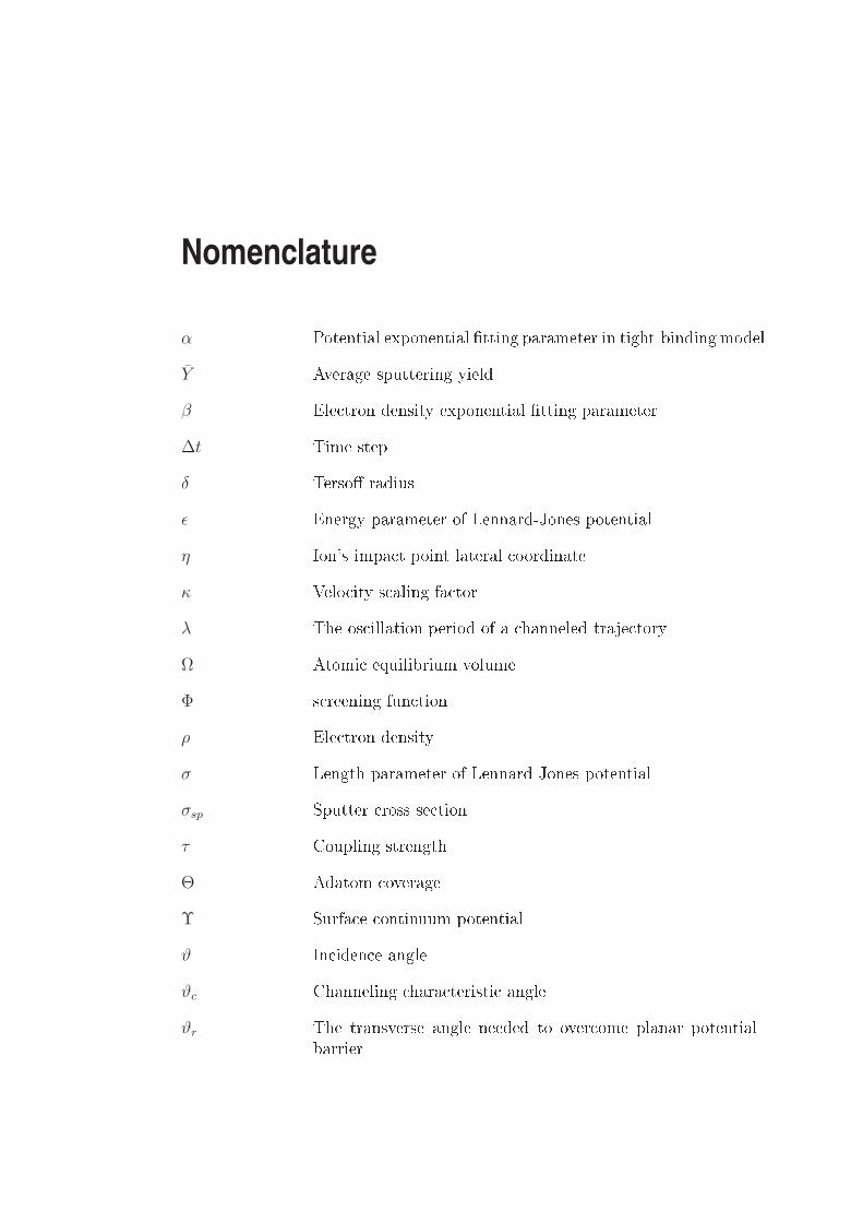
α Potential exponential tting parameter in tight-bindingmodelY Average sputtering yieldβ Ele tron density exponential tting parameter∆t Time stepδ Terso radiusǫ Energy parameter of Lennard-Jones potentialη Ion's impa t point lateral oordinateκ Velo ity s aling fa torλ The os illation period of a hanneled traje toryΩ Atomi equilibrium volumeΦ s reening fun tionρ Ele tron densityσ Length parameter of Lennard-Jones potentialσsp Sputter ross se tionτ Coupling strengthΘ Adatom overageΥ Surfa e ontinuum potentialϑ In iden e angleϑc Channeling hara teristi angleϑr The transverse angle needed to over ome planar potentialbarrier

xxii NOMENCLATUREϑ1/2 Channeling riti al angle~Fi Atomi for e a ting on ith atom~v Velo ityξ Ion's impa t point oordinateA Areaa S reening radiusAstep Area of zone of inuen eA0 Cross se tional area of an atomaB Bohr radiusai Amplitude oe ientsAad Area of an adatomAeff Sputtering ee tive areaaTF Thomas-Fermi s reening radiusB Bulk modulusbi Exponential oe ientsC The spline oe ientd Distan e between atom in an atomi rowdp Distan e between atomi planese The elementary hargeETB Tight binding energyE⊥ Transverse energyEB Barrier energyEsub Sublimation energyEtot Total energyF Embedding fun tionfT Terso fun tion

NOMENCLATURE xxiiigi The ontribution of an atom to ele tron densityh The layer distan e of (111) surfa el, LC Latti e onstantL⊥ The proje ted length of as ending island stepNs Atomi areal number densityNion Number of impa ting ionsNrel Number of relo ated atomsrc Cut radius of a Potentialrclc Distan e riterion of a luster membershiprNN Nearest neighbor distan ersc Shadow one radiusS The spline fun tionU Continuum potentialV Potential fun tionxc Geometri al hara teristi distan e of ion beamXsp Sputtering lengthXML Crystallite monolayer distan es in x-axisY step Step edge sputter yieldY terr Terra e sputter yieldyN Sputter oe ient of N-sized adatom lusterYad Adatom yieldYsp Sputtering yieldYML Crystallite monolayer distan es in y-axisZ Atomi numberzc The losest approa hZML Crystallite monolayer distan es in z-axis

Chapter 1
IntroductionIon assisted surfa e modi ation is an important method for reating ultra nestru tures in the order of nanometers. With the help of fo used ion beam (FIB)te hnique, for example, it is possible to reate stru tures in the s ale of severalnanometers. Nowadays, the te hnique is apable to reate tren hes and wallson the surfa e having width of tenth nanometers [3, 4. On the other hand,low energy ion sputtering method has also been used to indu e the reationof nanodots with size in the order of 20 to 50 nanometers [5. The appli ationof patterned surfa e is also very broad, for example: nano-s ulpture, tuningsurfa e magnetism, and fabri ation of high-resolution liquid- rystal displays[6, 7, 8.The behavior of pattern formation in nanometer s ale has not been fullyinvestigated. This realm of surfa e s ien e is still interesting to be explored.The study of initial pro esses in surfa e patterning is of importan e in ndingout a better method on surfa e ne-stru ture reation. The detailed studyis fa ilitated by the dis overy of atomi s ale measurement devi es, su h asatomi for e mi ros opy (AFM) and s anning tunneling mi ros opy (STM).Using these devi es one an probe dire tly the surfa e, and see its morphologyas the ee t of ion bombardment, also dire tly in pla e.Currently, from theoreti al side the behavior an be well explored by meansof omputer simulations. One of the hoi es, whi h is relevant to this work, isthe mole ular dynami s simulation. As measuring devi es evolve in the dire -tion of dete ting smaller obje ts, the al ulating power of a modern omputertends to in rease, make it possible to simulate larger systems. This is a verybene ial synergy whi h gives the opportunity for omputer-physi ist to in-terpret the results better. The agreement between simulation and experimentwill be ome a very onvin ing proof, and an be a base for dis overing newmethods of material fabri ation in this s ale.In the regime of low uen e ion bombardment, the ee t of single ionimpa t to a surfa e is visible. Here one an tra e the theoreti al ba kgroundof the surfa e pattern formation. The su essive employment of low densityion ux and STM measurement shows exa tly the defe ts reated by single ion
