e-bike and wheelchair motor control · pdf filee-bike and wheelchair motor control circuit ......
TRANSCRIPT

1
E-Bike and Wheelchair Motor Control Circuit
ECE 480 Team 9 for
Resource Center for Persons with Disabilities
Tyler Borysiak
Stephen Dunn
Myles Moore
Joshua Lamb
Alex Sklar
Dr. Virginia Ayres - Facilitator
Mr. Stephen Blosser - Sponsor
Final Proposal
Friday, October 9, 2015
Michigan State University

2
Executive Summary
Electric vehicles are in high demand around the world and especially in India as a
low cost, high independence, rugged form of transport. Typically, they are
powered through the use of a costly class of electric motor, the direct-current DC
motor. To combat this problem, ECE 480 Team 9 proposes the use of an
inexpensive automotive alternator that would replace the DC motor, providing
higher efficiency and increased torque at wider ranges of speed. The proposed
design makes use of a high-speed sensor that will measure the magnetic field
produced by a uniquely polarized magnet. These have the ability to provide high
resolution angle information to a microprocessor. With this data, the
microprocessor holds the potential to increase efficiency of electric motors by
applying precise power pulses at optimal positions within the motor as it rotates.
By controlling the magnetic field, motor efficiency can be increased, the motor can
be used for regenerative braking to recharge the battery and it can provide
enhanced stopping performance.

3
Table of Contents
Motivation Page 4
Summary of Benefits Page 4
Motor Concepts Page 5
Sensor Concepts Page 6
Microcontroller Concepts Page 7
Budget Page 9
Project Management Plan Page 10
References Page 12
4
Motivation: In a novel entrepreneurial enterprise, Dr. Pauliah and his sister Ms. Pauliah of the
Sunrise Orphanage in Bobbili, India, are seeking a product that can be
manufactured and sold to help support the orphanage and add a low-cost medical
clinic to the existing facility. Michigan State University is affiliated with the
Sunrise Orphanage and its future clinic through Asian Aid USA, a Christian
nonprofit organization that is committed to making a difference in the lives of
children and people in poverty. Asian Aid High School students in Jaipur, India
learn electronic circuit design from Stephen Blosser, an Assistive Technology
Specialist at the Resource Center for Persons with Disabilities. Mr. Blosser is an
honorary ambassador volunteer with orphanages in the area and helps choose
technology for the orphanage members to work with. He has designed an electric
tricycle, which is in high demand in India and around the world. This tricycle
could be manufactured by student employees such as those residing at the
orphanage. Students at the orphanage sponsored by Asian Aid would benefit from
the learning experience that the manufacture and sale of these tricycles would
provide, as well as benefitting from the part-time employment.
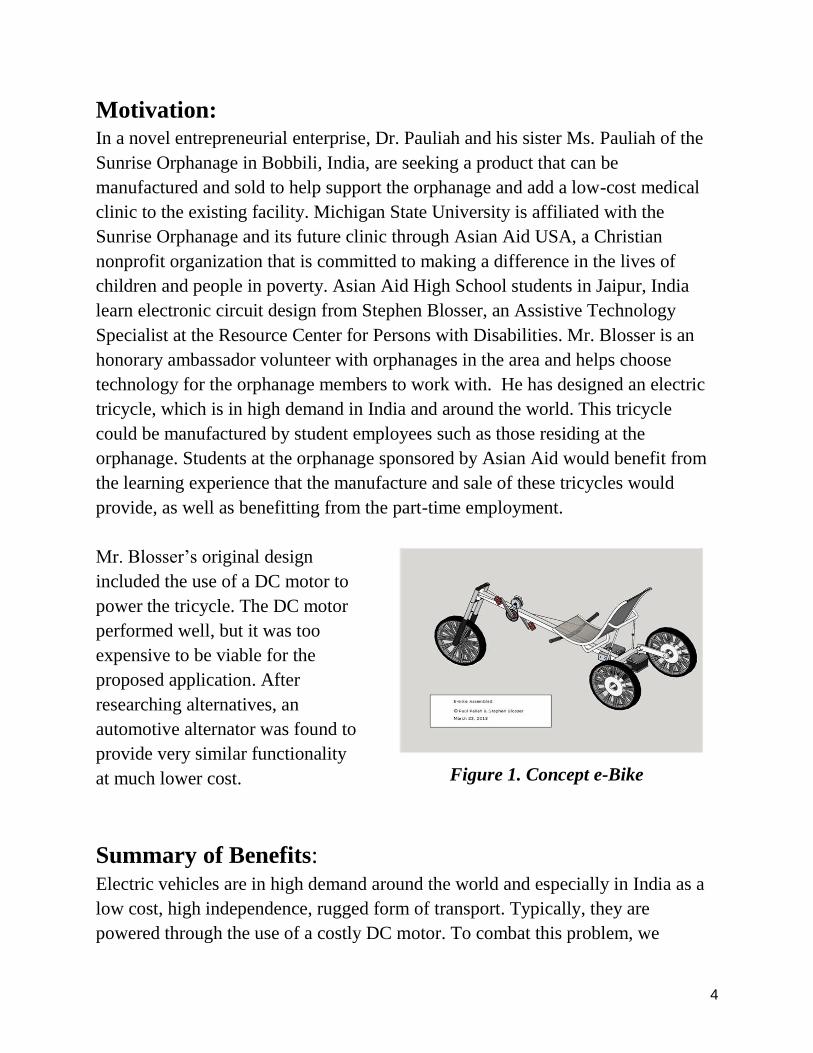
Mr. Blosser’s original design
included the use of a DC motor to
power the tricycle. The DC motor
performed well, but it was too
expensive to be viable for the
proposed application. After
researching alternatives, an
automotive alternator was found to
provide very similar functionality
at much lower cost.
Summary of Benefits: Electric vehicles are in high demand around the world and especially in India as a
low cost, high independence, rugged form of transport. Typically, they are
powered through the use of a costly DC motor. To combat this problem, we
Figure 1. Concept e-Bike

5
propose the use of an inexpensive automotive alternator that would replace the DC
motor providing higher efficiency and increased torque at wider ranges of speed.
The proposed design makes use of a high-speed sensor that will measure the
magnetic field produced by a uniquely polarized magnet. These chips, with high
resolution feedback, hold the potential to increase efficiency of motors by applying
precise power pulses at optimal angles. By controlling the field, we can also
enhance regenerative braking and stopping performance.
This design concept has the potential for use in other applications that require
electric motors. The goal is to design a robust, efficient, and inexpensive motor
that can be utilized in numerous other future products.
To accomplish the design goals required by the Sponsor, three key sub goal
choices must be investigated: sensors, motor and microprocessor.
Motor Concepts: We have chosen to use
automotive alternators as the
motors for this application.
Alternatively, it would be
possible to use DC brushless
electric motors to accomplish
the same task. These DC motors
are typically highly efficient and
require little to no complex
hardware or software in order to
operate. However, DC motors used
in electric vehicle design are
generally very expensive due to the large rare-earth magnets used in their
construction. This fact has led our team to pursue the conversion of an automotive
alternator to be used as a motor. This choice requires the development of more
complex hardware and software in order to drive the unusual motor configuration,
Figure 2. Automotive alternator with
reconfigurable options: stator, rectifier
and rotor.

6
but allows for cost savings that far outweigh the additional complexities. This cost
advantage is one of the key design choices in this proposal.
The automotive alternators used in this design are of the hybrid-brushless variety,
having no expensive, internal rare-earth permanent magnets. Instead, the motors
require that a small amount of current be passed through brushes to a coil in the
rotor in order to magnetize it. Current is then applied to the outer stator coils in
order to induce an electromagnetic force to turn the rotor. The stator has 36 coils
around its perimeter. The test alternators have 36 coils that are wired into 3 phases
connected in a “delta” pattern such that each phase has 12 coils and each coil is
separated by 10 degrees around the stator. The software algorithm and supporting
hardware will need to be able to drive this motor configuration.
Sensor Concepts: In order to effectively control the operation of
the alternator running in a motor configuration,
the absolute angle of the rotor shaft will need
to be sensed at a high frequency. A hall effect-
sensor for measuring the magnetic field of a
spinning magnet provides a unique solution.
The sensor is available either as a stand-alone
electrical sensor or as part of an integrated
chip with a common communication bus to
connect to a microcontroller. The Avago
AEAT-6600-T16 angular magnetic encoder is
one solution with high resolution for
measuring precise angles of the magnetic field
as the magnet spins. This chip provides a
complete solution with an integrated
communication interface, however the cost of $8.04 per chip led to further research
into finding a lower cost solution. The chip chosen to accomplish the task is the
AS5132 Programmable High Speed Magnetic Rotary Encoder manufactured by
AMS, which costs $6.05 per chip. The AS5132 is also readily available pre-
Figure 3. Hall Effect rotary
position sensor and diametric
magnet [4].

7
soldered to a computer board, which will decrease the time for development. The
AS5132 is capable of sensing the absolute orientation of a nearby magnetic field
and report the value in degrees between 0 and 359. The lower resolution should be
sufficient at the expected rotational speeds. A small magnet will be affixed to the
end of the rotor shaft and the chip will be placed directly over this magnet. This
will allow the absolute position of the motor shaft to be known at any point in time.
Additionally, the AS5132 is able to communicate over a synchronous serial
interface allowing fast and precise communication of the angle of the motor shaft
to the microcontroller.
The sensor must use a magnet that has a diametrical magnetization direction. This
means that the magnet is magnetized across its diameter, with its north pole on the
top semicircular half while the south-pole is at the bottom of the semicircular half.
In order to control the torque of the motor according to the desires of the rider, it
will be necessary to have some a throttle that the user is able to turn in order to
have the motor apply more or less torque through the drivetrain. For this task, a
popular Hall-effect sensor based throttle meant for scooter applications is under
consideration.
Microcontroller concepts: Driving an automotive alternator as a motor
requires the use of a microcontroller in order to
collect sensor data and compute when and how
to energize the rotor and stator coils. In order
to support high-speed operation of the motor,
the microcontroller needs to be able to operate
quickly. It has been theorized that having a
hardware floating point unit on the chip will
greatly increase the speed of the control
algorithms. Additionally, the microcontroller
needs to be able to communicate directly with
the throttle and AS5132 sensors as well as the
Figure 4. Texas Instruments
development board for an ARM
Cortex M4 microcontroller [5].

8
driver board for the stator coils. Finally, in order to facilitate rapid software
development, a development board with integrated debugging capabilities will be
required. For this task we have chosen the Tiva-C Series EK-TM4C123GXL
development board from Texas Instruments. The microcontroller on the
development board is the TM4C123GH6PM, which is expected to meet or exceed
all of the required capabilities, operating at a maximum clock frequency of 80MHz
and containing the previously mentioned floating point hardware. This
microcontroller and the use of a development board is expected to ease the creation
of the software algorithm.
Texas Instruments officially supports this board through two software packages,
Energia and Code Composer. Energia is a lightweight development software with
basic development features intended to allow the hobbyist to quickly unlock the
capabilities of the hardware. However, it lacks many of the features of a full
integrated development environment, such as debugging. Code Composer provides
a more feature complete solution at the expense of some added complexity.
However, for a software solution of the scale required for this project, Code
Composer and the accompanying TivaWare software library for our development
board are envisioned to provide us with the necessary tools to write a performant
and efficient motor controller solution.

9
Conceptual Diagram: The following is a high-level block diagram pertaining to the proposed design. The
48V power supply is the main source of power for the circuit. The microcontroller
receives the speed input from a Hall-Effect throttle and a shaft position input from
the AMS rotary sensor chip. This allows the microcontroller to control the current
provided to the rotor and stator.

10
Risk Analysis:
Technical:
The alternator will require a high voltage, between 24 and 48 volts, and a high
current, potentially higher than 50 amps. The circuit may use a lot of power which
has the potential to cause a large amount of heat to be generated. This can lead to
overheating and damage if the circuit is not cooled properly. Using under-rated
components could increase the risk of circuit damage.
There is a small risk that the salvaged alternators proposed for this application may
have been damaged (physically or electrically) in prior use, however many of the
components likely to have failed will be replaced as a part of this proposed
solution. Additionally, a proper battery management and protection system will be
crucial to the final design in order to ensure the battery pack is operating within
safe limits.
Financial:
There is good reason to believe the parts used in this proposed design can be
acquired in bulk for a discounted price. Due to supply uncertainties, there is a
small risk that production of the final design could be interrupted or the component
costs may increase.

11
Fast Diagram: The primary function of the automotive alternator design proposal is to control the
vehicle’s speed using a microcontroller to apply pulses at optimal angles. This is
achieved by switching MOSFETs that are connected to both the stator and rotor
windings. To apply torque and increase the speed, power is applied from the
batteries to the stator coils in the proper sequence. To apply regenerative braking
and slow down the vehicle, the stator coils will be connected to a rectifying circuit
and the rotor will be energized using short pulses.

12
Budget: One of the key constraints of this project is developing a design that is both highly
efficient and cost effective. The most expensive portion of the project will be the
automotive alternators, which cost around $20 to $30. The use of these alternators
instead of brushless DC motors will save at least $60 per motor. Like most of the
parts that are required for this project, the automotive alternators were already
provided to the team; therefore we will not track their cost in our $500 budget.
Additional parts that were needed include the diametrically magnetized magnet,
the AMS AS5132 rotary sensor, and an external throttle.
Part
Description
Quantity Cost of Each
Part
Shipping Cost
Total
Total Cost
with Shipping
¼’ x ⅛’
magnets
4 $0.38 --------- ---------
½’ x ⅛’
magnets
4 $1.13 $11.00 $17.04
AMS AS5132
Adapter Board
4 $16.12 $8.08 $72.56
Hall Effect
Throttle
1 $14.99 ~$5.00 $19.99
MOSFET N-
Ch 100V 100A
6 $2.86 --------- ---------
MOSFET P-
Ch 100V 76A
6 $4.59 ~$6.00 $50.70
Total Cost
(tentative)
$160.29

13
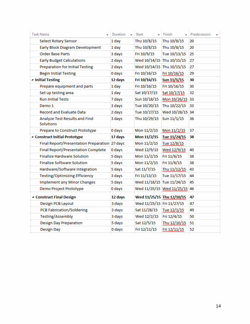
Project Management Plan:
Gantt Chart:
The project timeline consists of seven main phases. These phases include project
definition, research of new designs, development of conceptual designs, initial
prototype preparation, initial testing, initial prototype construction, and final design
construction.
14

15
Role Descriptions:
Hardware Specialists:
Responsible for designing the power MOSFET switching circuits, any necessary
modifications to the rotor and stator, and the high-voltage power supply for the
entire system. Additionally, these specialists will make sure that the whole system
has proper electrical and thermal protection.
Tyler Borysiak – Project Manager
Responsible for managing the whole project and verifying that the project is
produced on time, with quality, and at the lowest cost. Responsible for
setting up the weekly meetings with the facilitator and sponsor.
Alex Sklar – Lab Coordinator
Responsible for ordering the necessary parts that are required for the
MOSFET switching circuits. This involves finding the optimal parts
required at the lowest cost. Additionally, Alex maintains the lab equipment
and ensures proper adherence to the lab safety requirements.
Myles Moore – Document Preparation
Responsible for preparing all documents which includes the coordination,
revision, and editing of all deliverables.
Software Specialists:
Responsible for implementing the motor control algorithm which will effectively
interface with the AMS sensor, throttle sensor, and the power MOSFET switching
circuits.
Stephen Dunn - Webmaster
Responsible for establishing and updating the website page for the design
team which includes all related project information. The website will be the
interface to the outside world.
Joshua Lamb – Presentation Preparation
Responsible for editing and preparing all presentations. Additionally, Joshua
makes sure that all of the equipment works properly during each
presentation.

16
References:
1. Asian Aid
http://www.asianaid.org/projects?projectId=14
2. Stephen Blosser
https://www.rcpd.msu.edu/about/teamrcpd/stephen-blosser
3. Avago AEAT-6600-T16
http://www.avagotech.com/products/motion-control-encoders/magnetic-
encoders/aeat-6600-t16
4. AMS AS5132
http://ams.com/eng/Products/Position-Sensors/Magnetic-Rotary-Position-
Sensors/AS5132
5. Texas Instruments TM4C123GXL
http://www.ti.com/tool/ek-tm4c123gxl
6. Texas Instruments TM4C123GH6PM
http://www.ti.com/product/tm4c123gh6pm
7. Texas Instruments Launchpad Software
http://www.ti.com/ww/en/launchpad/software.html?DCMP=mcu-
launchpad&HQS=launchpadsoftware