e-626-a real-time embedded systems (rtes) lecture …bu.edu.eg/portal/uploads/engineering,...
TRANSCRIPT
Lecture #4 Parallel Ports, Power Supply & Clock Oscillator Instructor: Dr. Ahmad El-Banna
SPR
IN
G 2
015
E-626-A Real-Time Embedded Systems (RTES)
Integrated Technical Education Cluster At AlAmeeria
© A
hmad
El-B
anna

Agenda
Parallel Input/Output
Parallel Interface
Connecting to the Parallel Port
Clock Oscillator
Power Supply
Example 2
RTES
, Lec
#4 , S
prin
g 201
5 ©
Ahm
ad E
l-Ban
na

The main idea – parallel input/output
• Almost any embedded system needs to transfer digital data between its CPU and the outside world.
• This transfer falls into a number of categories, which can be summarized as:
• Direct user interface, including switches, keypads, light-emitting diodes (LEDs) and displays.
• Input measurement information, from external sensors, possibly being acquired through an analog-to-digital converter.
• Output control information, for example to motors or other actuators.
• Bulk data transfer to or from other systems or subsystems, moving in serial or parallel form, for example sending serial data to an external memory.
3
© A
hmad
El-B
anna
RT
ES, L
ec#4
, Spr
ing 2
015
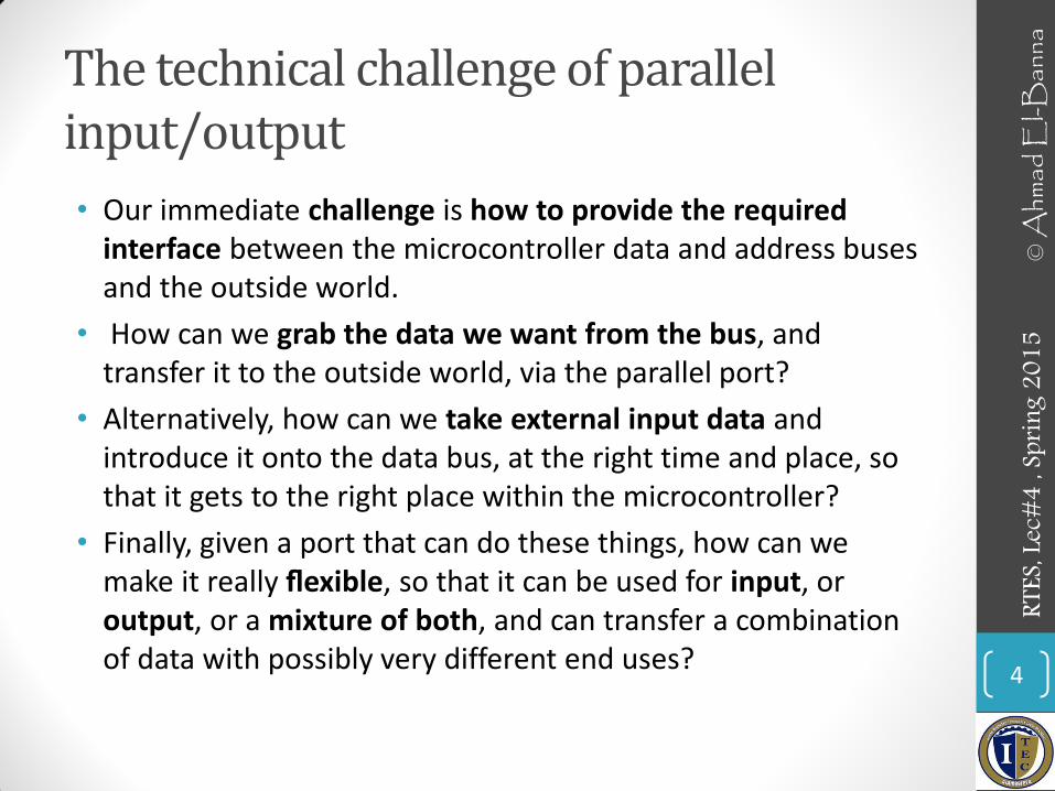
The technical challenge of parallel input/output
• Our immediate challenge is how to provide the required interface between the microcontroller data and address buses and the outside world.
• How can we grab the data we want from the bus, and transfer it to the outside world, via the parallel port?
• Alternatively, how can we take external input data and introduce it onto the data bus, at the right time and place, so that it gets to the right place within the microcontroller?
• Finally, given a port that can do these things, how can we make it really flexible, so that it can be used for input, or output, or a mixture of both, and can transfer a combination of data with possibly very different end uses?
4
© A
hmad
El-B
anna
RT
ES, L
ec#4
, Spr
ing 2
015

Building a parallel interface
5
© A
hmad
El-B
anna
RT
ES, L
ec#4
, Spr
ing 2
015
• Two bits of a possible digital output port

Two bits of a possible digital input port
6
© A
hmad
El-B
anna
RT
ES, L
ec#4
, Spr
ing 2
015
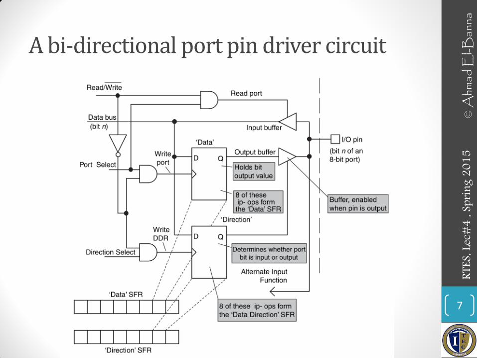
A bi-directional port pin driver circuit
7
© A
hmad
El-B
anna
RT
ES, L
ec#4
, Spr
ing 2
015

Connecting to the Parallel Port Switches & LEDS
8
© A
hmad
El-B
anna
RT
ES, L
ec#4
, Spr
ing 2
015

The clock oscillator
9
© A
hmad
El-B
anna
RT
ES, L
ec#4
, Spr
ing 2
015
• Types
• Oscillator frequency shows greater or lesser dependence on supply voltage, temperature, humidity, PCB layout and possibly other factors.
• Crystals in particular are sensitive to poor PCB layout. • It is important to exclude parasitic resistance, capacitance or inductance
by having very short PCB tracks, therefore locating the crystal close to the body of the microcontroller.
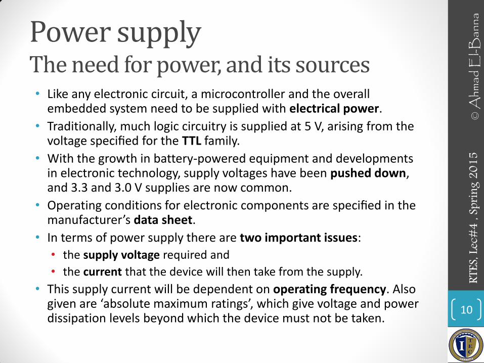
Power supply The need for power, and its sources • Like any electronic circuit, a microcontroller and the overall
embedded system need to be supplied with electrical power.
• Traditionally, much logic circuitry is supplied at 5 V, arising from the voltage specified for the TTL family.
• With the growth in battery-powered equipment and developments in electronic technology, supply voltages have been pushed down, and 3.3 and 3.0 V supplies are now common.
• Operating conditions for electronic components are specified in the manufacturer’s data sheet.
• In terms of power supply there are two important issues:
• the supply voltage required and
• the current that the device will then take from the supply.
• This supply current will be dependent on operating frequency. Also given are ‘absolute maximum ratings’, which give voltage and power dissipation levels beyond which the device must not be taken.
10
© A
hmad
El-B
anna
RT
ES, L
ec#4
, Spr
ing 2
015

16F84A operating conditions
11
© A
hmad
El-B
anna
RT
ES, L
ec#4
, Spr
ing 2
015

SIMPLE PROJECT 12
© A
hmad
El-B
anna
RT
ES, L
ec#4
, Spr
ing 2
015

13
IDE
Assembler
*.asm *.hex
Compiler Assembler *.c *.asm *.hex
© A
hmad
El-B
anna
RT
ES, L
ec#4
, Spr
ing 2
015

14
© A
hmad
El-B
anna
RT
ES, L
ec#4
, Spr
ing 2
015
15
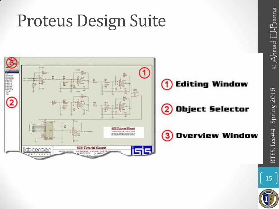
Proteus Design Suite
© A
hmad
El-B
anna
RT
ES, L
ec#4
, Spr
ing 2
015
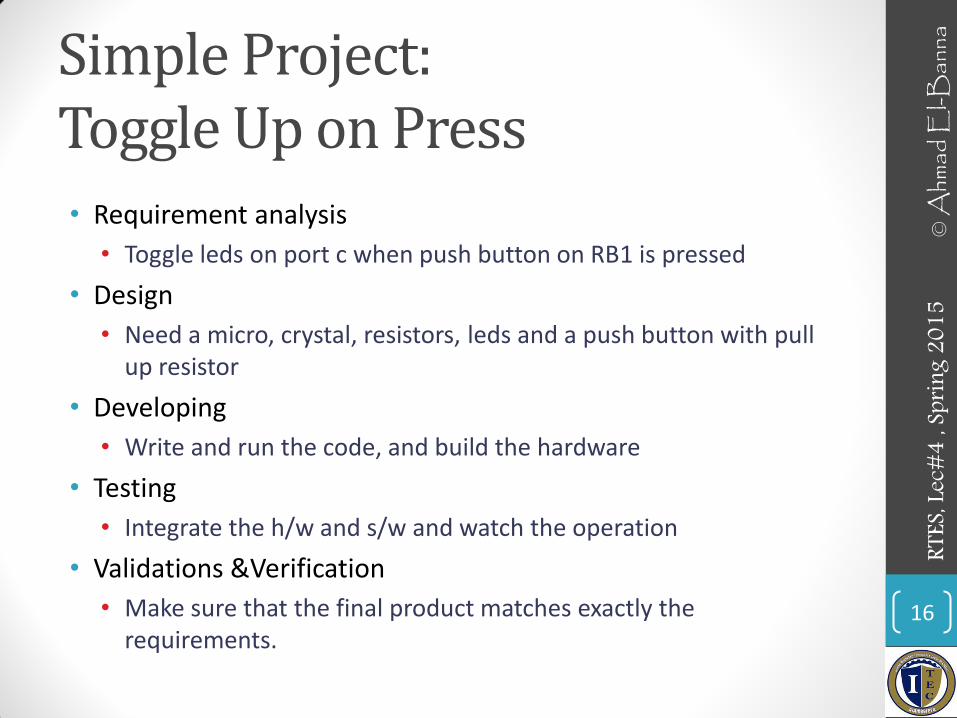
Simple Project: Toggle Up on Press • Requirement analysis
• Toggle leds on port c when push button on RB1 is pressed
• Design
• Need a micro, crystal, resistors, leds and a push button with pull up resistor
• Developing
• Write and run the code, and build the hardware
• Testing
• Integrate the h/w and s/w and watch the operation
• Validations &Verification
• Make sure that the final product matches exactly the requirements.
16
© A
hmad
El-B
anna
RT
ES, L
ec#4
, Spr
ing 2
015

Circuit view
17
© A
hmad
El-B
anna
RT
ES, L
ec#4
, Spr
ing 2
015

18
Pseudo code
• Start
• Configure port c direction as output
• Configure port B direction as input
• Initialize port value
• If key pressed, Toggle the port
• Delay to watch
• Loop infinitely
© A
hmad
El-B
anna
RT
ES, L
ec#4
, Spr
ing 2
015

19
code
© A
hmad
El-B
anna
RT
ES, L
ec#4
, Spr
ing 2
015
Your turn !
• Increment leds on every key press
• Go go
20
© A
hmad
El-B
anna
RT
ES, L
ec#4
, Spr
ing 2
015

• For more details, refer to:
• Chapter 3, T. Wilmishurst, Designing Embedded Systems with PIC Microcontrollers, 2010.
• The lecture is available online at:
• http://bu.edu.eg/staff/ahmad.elbanna-courses/12134
• For inquires, send to:
21
© A
hmad
El-B
anna
RT
ES, L
ec#4
, Spr
ing 2
015