e-09 september 16, 2009
TRANSCRIPT

E-09 September 16, 2009current software versions:cwt09.07, mth09.25mot09.07, dis09.06Download newest manual fromwww.tecnautic.comDirectory
Log Function ................................................................................................................................ 2Compass Display Function .......................................................................................................... 6Compass Compensation: do alignment first! ................................................................................ 7The Heading Gyro ....................................................................................................................... 8Turn Rate Display ........................................................................................................................ 8Wind Functions .......................................................................................................................... 10Depth Functions ........................................................................................................................ 12Nav Functions:........................................................................................................................... 15Programmed Track: .................................................................................................................... 15Bearing to WP ........................................................................................................................... 15Cross Track Error ....................................................................................................................... 15Distance to Waypoint ................................................................................................................. 15Jumbo Display: Function ............................................................................................................ 16Electric Helm connected to an AP-Display................................................................................. 17Turn Knob Functions of the Fly-By-Wire unit .............................................................................. 18Docking-Mode ........................................................................................................................... 19Autopilot Functions .................................................................................................................... 20Tiller button (Autopilot ON-OFF switch): .................................................................................... 21Additional Autopilot Functions for Yachts: ................................................................................... 21Set up of the Autopilot ................................................................................................................ 22Initial Operation ......................................................................................................................... 22Installation: Servo Steering without Display ............................................................................... 24Trim Flap Function ..................................................................................................................... 25Display Configuration ................................................................................................................. 26Sensor type Selection: ............................................................................................................... 26Display Type Selection: .............................................................................................................. 26Display Function: ....................................................................................................................... 27Autopilot Configuration ............................................................................................................... 27Illumination Group: .................................................................................................................... 27NMEA input and output .............................................................................................................. 28Configure the output of your GPS, Plotter or PC ........................................................................ 29Cabling ...................................................................................................................................... 30NMEA0183 Connection: ............................................................................................................ 31Log Sensor mechanical Installation ........................................................................................... 32Airmar CS4500 Ultra-Sonic Speed Sensor ................................................................................ 33Compass and Heading Gyro Installation ................................................................................... 34Echo-Box-1 and -2 ..................................................................................................................... 36Echo-Sensor Installation ............................................................................................................ 37Autopilot Connection .................................................................................................................. 40reversible rudder motor (mechanical or hydraulic) ..................................................................... 40non reversible pump with speed regulation and switch-over valve ............................................. 40continuous pump with switch-over valve .................................................................................... 41current controlled (non linear) proportional valve ....................................................................... 41with current controlled servo valve ............................................................................................. 41with voltage controlled servo valve ............................................................................................ 42Trim Flap Electronics ................................................................................................................. 42Rudder Angle Sensor Installation .............................................................................................. 43Linear Drive Unit: Installation ..................................................................................................... 44How to purge a Linear Drive after installation ............................................................................ 46Hydraulic Steering ..................................................................................................................... 46Pump Installation ....................................................................................................................... 46Installation of a check valve block .............................................................................................. 47Connectors, Plugs and Cables .................................................................................................. 48Autopilot FAIL message ............................................................................................................. 50Throttle Station Setup ................................................................................................................ 51
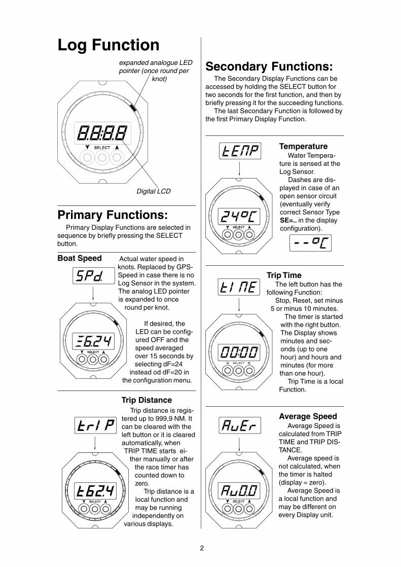
Log Function
Digital LCD
expanded analogue LEDpointer (once round per
knot)
Primary Functions:Primary Display Functions are selected in
sequence by briefly pressing the SELECTbutton.
2
Average Speed
SELECT
Trip Time
Trip DistanceTrip distance is regis-
tered up to 999,9 NM. Itcan be cleared with theleft button or it is clearedautomatically, whenTRIP TIME starts ei-
ther manually or afterthe race timer hascounted down tozero.
Trip distance is alocal function andmay be running
independently onvarious displays.
The left button has thefollowing Function:
Stop, Reset, set minus5 or minus 10 minutes.
The timer is startedwith the right button.The Display showsminutes and sec-onds (up to onehour) and hours andminutes (for morethan one hour).
Trip Time is a localFunction.
Boat Speed
TemperatureWater Tempera-
ture is sensed at theLog Sensor.
Dashes are dis-played in case of anopen sensor circuit(eventually verifycorrect Sensor TypeSE=.. in the displayconfiguration).
Average Speed iscalculated from TRIPTIME and TRIP DIS-TANCE.
Average speed isnot calculated, whenthe timer is halted(display = zero).
Average Speed isa local function andmay be different onevery Display unit.
Actual water speed inknots. Replaced by GPS-Speed in case there is noLog Sensor in the system.The analog LED pointeris expanded to once
round per knot.
If desired, theLED can be config-ured OFF and thespeed averagedover 15 seconds byselecting dF=24
instead od dF=20 inthe configuration menu.
Secondary Functions:The Secondary Display Functions can be
accessed by holding the SELECT button fortwo seconds for the first function, and then bybriefly pressing it for the succeeding functions.
The last Secondary Function is followed bythe first Primary Display Function.
3
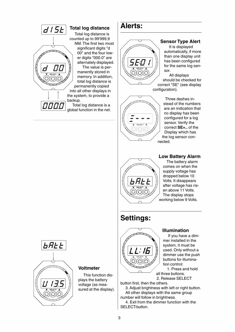
This function dis-plays the batteryvoltage (as mea-sured at the display).
Voltmeter
Total log distance
SELECT
Settings:
Total log distance iscounted up to 99'999,9
NM. The first two mostsignificant digits "d00" and the four low-er digits "000.0" arealternately displayed.
The value is per-manently stored inmemory. In addition,total log distance is
permanently copiedinto all other displays in
the system, to provide abackup.
Total log distance is aglobal function in the net.
Alerts:
Sensor Type AlertIt is displayed
automatically, if morethan one display unithas been configuredfor the same log sen-sor.
All displaysshould be checked for
correct "SE" (see displayconfiguration).
Three dashes in-stead of the numbersare an indication thatno display has beenconfigured for a logsensor. Verify thecorrect SE=.. of theDisplay which has
the log sensor con-nected.
Low Battery AlarmThe battery alarm
comes on when thesupply voltage hasdropped below 10Volts. It disappearsafter voltage has ris-en above 11 Volts.The display stops
working below 9 Volts.
IlluminationIf you have a dim-
mer installed in thesystem, it must beused. Only without adimmer use the pushbuttons for illumina-tion control:
1. Press and holdall three buttons.2. Release SELECT
button first, then the others.3. Adjust brightness with left or right button.All other displays with the same group
number will follow in brightness.4. Exit from the dimmer function with the
SELECT-button.
SELECT

4
The calibrationnumber can be en-tered only at thedisplay(s) where alog sensor is con-nected (and the Sen-sor Type Number hasbeen configured).1. Select Speed
Function2. Press both arrow buttons briefly.3. Adjust the calibration number "c" with the
left or right button. The calibration must bemade after installation, since the water speedin vicinity of the sensor may deviate by +/-20% from the boat speed, depending on thesensor location.
Standard Calibration Factor:Regatta Speed Sensor: C 50Cruise Speed Sensor: C 31Planing Speed Sensor: C 30Universal Speed Sensor: C 38Airmar Ultrasonic SpeedSensor (CS 4500): C 31
After modifying the calibration number, theindicated boat speed will change by the samerelative amount (e.g. changing the calibrationnumber from 50 to 55 will modify the speedindication from 10 to 11 knots).
An accurate calibration has to be done withthe Trip Distance counter. E.g. after running9,0 NM, the Trip Distance shows 10,0 NM. Inthis case, the calibration number has to bereduced by 10%. If it was 50, it should be setto 45 now.
If a weak set/current is present, the runhas to be made in two directions. Calibrationcan not be done with a strong current.
If desired, calibration can also be made inmph, km/h or m/s, except if a wind instrumentis connected to the bus, in which case the logmust be calibrated in knots.
Special case: should you wish to calibratetwo log sensors with different calibration num-bers, then the other display with the other logsensor should be disconnected from the busduring the process.
Log Calibration Log Speed received by NMEA:Log Speed (water speed) may be received
from a different instrument system throughNMEA data on any Tecnautic NMEA input(could be a Display unit, Fly-By-Wire unit,Autopilot Drivebox or Engine FADEC-Box).
The received log speed will be displayedand used in the same manner as if it werecoming from a log sensor. However it cannotbe recalibrated, and will not be used for thelog distance or trip counter.
Log Speed replaced by GPS-speed:In the absence of Log Speed Data, Water
Speed will be substituted automatically byGPS Ground-Speed.
This feature permits the use of the autopilotTrue Wind Mode, even in the absence of a logsensor.
Keep in mind, that True Wind data will beaffected whenever ground speed is not equalto water speed. With water speed available,true wind is shown relative to the water body.When ground speed is substituting waterspeed, true wind will be shown relative toground.
Remark: when water speed data are re-ceived from an external device and on a differ-ent NMEA-input than the GPS-speed, makesure that water speed data are received first,BEFORE GPS speed-data come into the sys-tem. The first source, with valid data will beused until next reset or power up of the unit.

5
Load SensorRig Load Display
Rig Load is displayedfrom zero to 49.9 kiloNe-wton (4.99t). Differentscales are available uponrequest.
Sensors from vari-ous suppliers can beconnected (Navtec,B&G).
Installation:A Tecnautic Load
Sensor Interfacemust be connected
between the sensor andthe cockpit display. The in-
terface can be calibrated for any particularsensor.
The display unit to which the Load Sensoris connected, has to be configured with sen-sor number SE=14.
At all display units, where the Rig LoadReading shall be enabled, function numberdF=28 must be activated.
SELECT
Sensor Cable:6 pin plug RJ-11 (4 pins installed)
6 pin plug, 4-wire cable:
pin round flat-oval# cable cable
1 ----- ----- unused2 white white +5 Volts3 brown blue GND4 yellow cyan Sensor signal5 green magenta reserved6 ----- ----- unused
pin 1 and 6 must remainunconnected
Important in case of third partysensor electronics:
All sensors (including their associated elec-tronics) must only be wired to the display unitvia its sensor cable. No other electric connec-tion between sensor and boat must exist. Thatmeans only the supply from the display (GNDand +5 Volts) may be used. The current drawnshould not exceed 25 mA and should besteady (+/- 1mA).
Pin #1
white lead onto pin#2

Alerts:
6
Analogue LED-pointerfor the selected heading(upper face of display).
Digital display (LCD) showsGyro Heading wheneverthe Gyro has beenslewed by a GPS or amagnetic compass
The selected headingis displayed afterpressing briefly eitherarrow button. Withevery following buttonapplication, the se-lected heading will bemodified by one de-
gree. For larger adjust-ments of the selected
heading, the left or rightbutton may be pressed and held.
After a few seconds of button-inactivity, theactual heading will come up again.
Selected Heading
The LCD showsthe actual heading,the LED-pointerpoints onto the se-lected heading (ex-panded scale).
The Gyro Symbol(the decimal behindthe H) should bemonitored, whenusing the autopilot.
Heading Hold
Compass Display Function
Second LED-pointer for rudderangle (lower face of display)
Heading SensorDashes on the
heading display arean indication, that nocompass sensor hasbeen connected orthat no valid headingsignal is received
from the sensor.Verify, that the NMEA
input of the display, whichhas the heading sensor connected, is config-ured correctly: n0=01 for the primary compassor n0=02 for an eventual secondary compass(and also n1=00 for the HS8000 or n1=07 forthe PB200 or H2183 Sensor). See page 28 forNMEA setup.
Low Battery AlarmThe battery alert
comes on when thesupply voltage hasdropped below 10Volts. It disappearsonly after voltage hasrisen above 11 Volts.The display stops
working below 9 Volts.
Decimal-Symbol indi-cates Heading Gyroreadiness (appears 5minutes after power-up, when the gyro isslewed, but can takemuch longer without aslewing heading source).The autopilot must not beused without an operationalgyro!
Gyro AlarmThe warning is
shown on AP dis-plays, if a previouslyoperational gyro hasfailed or is in align-ment mode or hasan abnormal signal.The dot behind the"H" is the gyro ONsymbol.Gyro Signal "F"
The gyro signalalert comes on, if thesignal is abnormal.Numbers below 26and above 103should only be ac-cepted for a shorttime after alignment.
Not valid for six-button AutopilotDisplays

7
AP
CompensationStatus Display:
The compensationstatus display followsthe alignment correc-tion display (see left).
means "notcompensated", means "compensat-ed".
ATTENTION: com-pensation status is not
correctly displayed aftera new installation or afterthe sensor or display havebeen replaced.
A new compensationcan be started by briefly
pressing the left or right button (see below).The middle button exits from the compensa-
tion function.
Starting a new com-pensation cycle
1. Select the com-pensation status on theDisplay (see above).
2. Briefly press theleft or right button.
3. Start turning (forthe HS8000 a star-board turn through 540degrees is required, forother sensors only a full
turn to either side isneeded).The turn has to be com-
pleted within one to three min-utes and must be executed under perfectlysmooth conditions. The vessel must not beheeled. Power lines or steel structures below ornear the vessel must be avoided. A significantdepth and a distance of several hundred meters(a few hundred yards) from bridges or buildingswould present acceptable conditions.
Completion of a compensation cycle is indi-cated by CAL-Auto (or by CAL-OFF if not suc-cessful).
WARNING: executing a compensation bearsthe risk of introducing large compensation er-rors. A bad compensation can only be overwrit-ten by a good one. The quality of a compensa-tion cycle has to be verified with a newly pro-duced deviation table.
Compass Compensa-tion: do alignment first!
Sensor compensation and alignment func-tion are only accessible on the display unit, towhich the sensor is physically connected viathe NMEA port, and the port has been proper-ly configured n0=01 for the primary compassor n0=02 for a secondary compass, andn1=00 for the HS8000 or n1=07 for the PB200or H2183.
AP
Aligning the Sensor
Reading the previ-ously saved align-
ment correction
1. Press and holdleft and right button.
2. Press middlebutton twice.
3. Release allthree buttons.
For example"C_02" will stand for an
alignment correction of +2 degrees. The valuemay be modified with the left or right button. Thiscorrection is added automatically to the sensedheading. Press the middle button again to dis-play the compensation status function.
Alignment ProcedureFirst you need to create a deviation table. That
will be the basis for a correct sensor alignment.The deviation table might have positive and neg-ative numbers over the full circle.
A deviation table can only be created by tak-ing relative bearings of distant objects and com-paring them with the indicated heading. Neveruse GPS tracks to build a deviation table.
With the table at hand, adjust the alignmentcorrection "C" (offset) until negative and posi-tive deviation values become equal in size.
Note: on the PB100/200 sensor, the offsetcorrection will also be valid for the apparent windangle.
ATTENTION: the Alignment Correction maynot be displayed correctly after (re-) installingeither the sensor or the display unit, to whichthe sensor is connected. The correction mustbe verified in this case.

8
Turn RateThe turn rate display
is available with theHeading Gyro installedand aligned. Note that ittakes 5 minutes after a
power interruption untilthe gyro is aligned.
The digital LCDdisplays rate of turnup to +/- 25 degreesper second.
The LED pointeris an expanded ana-
log indicator up to +/-four degrees per second
(upper half LED circle). The lower half LED cir-cle displays the rudder angle, if available.
SELECT
Turn Rate Display
Settings:
SELECT
IlluminationIf you have a dim-
mer installed in thesystem, use only thedimmer. Otherwise usethe push buttons for il-lumination control:
1. Press and hold allthree buttons.
2. Release SELECTbutton first, then the others.3. Adjust brightness with
left or right button.All other displays with the same group num-
ber will follow in brightness.4. Exit from the function with the SELECT-
button.
The Heading GyroThe Tecnautic Sonic Gyro is a so called
Heading Gyro. As opposed to a north seekinggyro, it needs to be aligned externally. Thereaf-ter it still requires continuous slewing, to avoiddrifting away from north due to earth rotationand gyro drift.
The means for slewing the gyro can be se-lected in the sensor setup (page 27).
Beside of "not knowing NORTH", the head-ing gyro has all the qualities of a gyro compass,it is immune to linear acceleration and magnet-ic influences. It senses solely the instant rate ofturn and the heading of the vessel, without de-lay.
After power up, the gyro goes through anautomatic alignment and stabilization phase,which normally lasts five minutes. Thereafter itis available for use by the display and the auto-pilot.
Slewing by a Magnetic CompassWith a magnetic compass in the system, the
heading gyro can be slewed to magnetic north.Coupling of the magnetic compass to the
gyro is very weak, in order to avoid reflection ofshort term fluctuations (in the range of seconds)onto the gyro heading.
In the longer term however (within minutes),the gyro will be slewed to the average headingof the magnetic compass.
Slewing by a GPSWith a GPS in the system, the gyro can be
slewed to the GPS course. In this case the gyroheading represents course over ground insteadof direction of the bow.
Slewing to a GPS is halted below speeds of2 knots.
Course data from the GPS must not bedampened or delayed by more than one sec-ond.
Slewing a gyro to the GPS course is not rec-ommended in rapidly changing drift conditions.
Free running Heading GyroWithout a magnetic compass or a moving
GPS, there is no slewing of the gyro. Neverthe-less the gyro is available to the autopilot after aprolonged stabilization phase. The AutopilotHeading Mode cannot be selected from theHeading Display (which shows no heading inthis case), but from the tiller button.
The Turn-Rate Mode can be engaged fromthe Fly-By-Wire station. Small heading adjust-ments need to be made from time to time, tocounter the gyro drift.
The Autopilot Wind Modes are available un-restricted, the gyro drift has no effect.

9
Engaging the Autopilot(Valid only for a three button display unit. -
- For an Autopilot Display see page 20)The autopilot function is
only available if during con-figuration "di:02" has beenset.
Press and hold the AP-button (middle button).
When the autopilot getsengaged after twoseconds, release thebutton. The digital dis-play shows briefly theautopilot number(AP1 or 2) and thenthe selected heading.
Initially the actual head-ing is stored as selected
heading.
Disengaging theAutopilot
This autopilot func-tion is only available if"di:02" was set duringconfiguration.
Press the AP-but-ton briefly to disen-gage the autopilot im-mediately. The OFF-alert will come on. Itmay be cleared by
briefly pressing any ofthe three buttons.
Special Display Config-uration
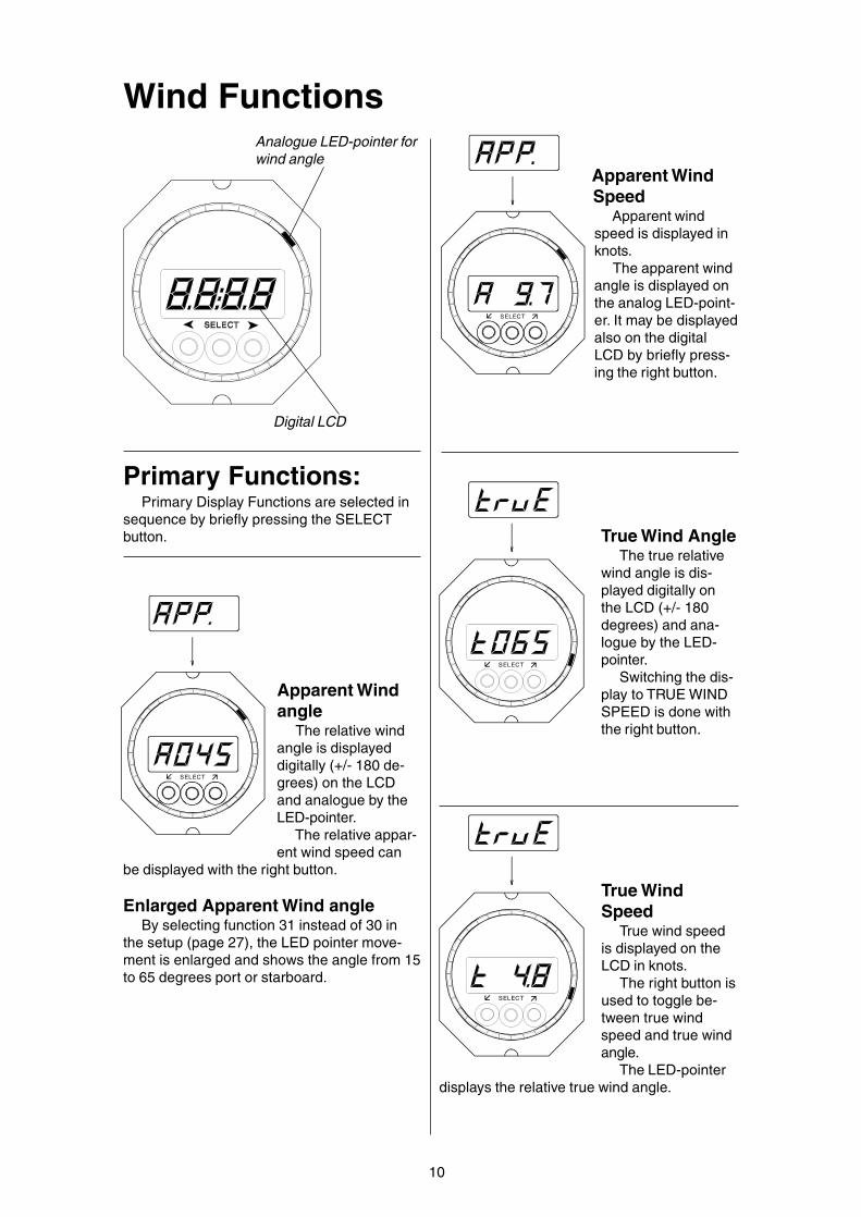
Wind Functions
Digital LCD
Analogue LED-pointer forwind angle
10
SELECT
SELECT
SELECT
SELECT
Primary Functions:Primary Display Functions are selected in
sequence by briefly pressing the SELECTbutton.
Apparent Windangle
The relative windangle is displayeddigitally (+/- 180 de-grees) on the LCDand analogue by theLED-pointer.
The relative appar-ent wind speed can
be displayed with the right button.
Enlarged Apparent Wind angleBy selecting function 31 instead of 30 in
the setup (page 27), the LED pointer move-ment is enlarged and shows the angle from 15to 65 degrees port or starboard.
Apparent WindSpeed
Apparent windspeed is displayed inknots.
The apparent windangle is displayed onthe analog LED-point-er. It may be displayedalso on the digitalLCD by briefly press-ing the right button.
True Wind AngleThe true relative
wind angle is dis-played digitally onthe LCD (+/- 180degrees) and ana-logue by the LED-pointer.
Switching the dis-play to TRUE WINDSPEED is done withthe right button.
True WindSpeed
True wind speedis displayed on theLCD in knots.
The right button isused to toggle be-tween true windspeed and true windangle.
The LED-pointerdisplays the relative true wind angle.

11
SELECT
SELECT
SELECT
Warnings
Settings
Secondary Functions:The Secondary Display Functions can be
accessed by holding the SELECT button fortwo seconds for the first function, and then bybriefly pressing it for the succeeding functions.
The last Secondary Function is followed bythe first Primary Display Function.
Magnetic WindThis function re-
quires a headingsensor in the system.
The magneticwind direction or truewind speed can beselected alternatelywith the right button.
The analogueLED shows the rela-tive angle of truewind.
VMGThis is the part of
the boat speed indirection of the truewind vector, eitherupwind or downwind.
The analogue LEDshows the relativetrue wind angle.
Low Battery AlarmThe battery alert
comes on when thesupply voltage hasdropped below 10Volts. It disappearsonly after voltage hasincreased above 11Volts. The displaystops working below9 Volts.
LCD blinking
Sensor WarningDashes on the LCD arean indication that valid
signals are not re-ceived from the sen-sor (or the wind vanesits at zero degreesfor a prolonged peri-od). Check also, thatthe configuration of
the display with thewind sensor physically
connected is SE=06 or 07 (n0=01 or 02 forthe PB100/200 wind sensor).
Tecnautic Wind Vane CorrectionThis correction
has to be done at adisplay unit with thewind sensor physi-cally connected andthe sensor typenumber correctlyconfigured and theapparent wind func-
tion displayed.
The wind angle can be corrected by alter-ing the correction "C".
1. Select the wind function, then press botharrow buttons briefly at the same time.
2. Use the right button to increase a star-board wind angle or to decrease a port windangle.
Use the left button to increase a port windangle or to decrease a starboard wind angle.
3. Exit the function with the middle button.PB100/200 Wind Sensor
The compass alignment function of thePB100/200 will also align the wind angle.
SELECT
IlluminationIf you have a dimmer installed in the sys-
tem, use only the dimmer.Otherwise use thepush buttons for illu-mination control:
1. Press and holdall three buttons.
2. ReleaseSELECT button first,then the others.
3. Adjust brightnesswith left or right button.
All other displays with the same groupnumber will follow in brightness.
4. Exit from the function with the SELECT-button.
12
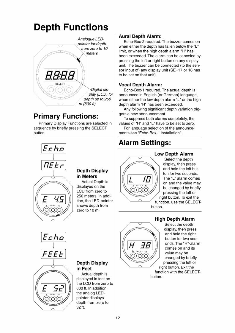
Depth Functions
Digital dis-play (LCD) for
depth up to 250m (800 ft)
SELECT
Depth Displayin Meters
Actual Depth isdisplayed on theLCD from zero to250 meters. In addi-tion, the LED-pointershows depth fromzero to 10 m.
SELECT
Depth Displayin Feet
Actual depth isdisplayed in feet onthe LCD from zero to800 ft. In addition,the analog LED-pointer displaysdepth from zero to32 ft.
Analogue LED-pointer for depth
from zero to 10meters
Alarm Settings:
SELECT
SELECT
ä
ä
High Depth AlarmSelect the depthdisplay, then pressand hold the rightbutton for two sec-onds. The "H"-alarmcomes on and itsvalue may bechanged by briefly
pressing the left orright button. Exit the
function with the SELECT-button.
Primary Functions:Primary Display Functions are selected in
sequence by briefly pressing the SELECTbutton.
Aural Depth Alarm:Echo-Box-2 required. The buzzer comes on
when either the depth has fallen below the "L"limit, or when the high depth alarm "H" hasbeen exceeded. The alarm can be canceled bypressing the left or right button on any displayunit. The buzzer can be connected (to the sen-sor input of) any display unit (SE=17 or 18 hasto be set on that unit).
Vocal Depth Alarm:Echo-Box-1 required. The actual depth is
announced in English (or German) language,when either the low depth alarm "L" or the highdepth alarm "H" has been exceeded.
Any following significant depth variation trig-gers a new announcement.
To suppress both alarms completely, thevalues of "H" and "L" have to be set to zero.
For language selection of the announce-ments see "Echo-Box-1 installation".
Low Depth AlarmSelect the depth
display, then pressand hold the left but-ton for two seconds.The "L" alarm comeson and the value maybe changed by brieflypressing the left or
right button. To exit thefunction, use the SELECT-
button.

13
SELECT
Depth offset to keel or surface1. Select depth display
2. Press and holdboth arrow buttons fortwo seconds.
With a zero correc-tion setting (c 0.0),depth is measuredfrom the sensor loca-tion. A positive value
of "c" will be added tothe sensed depth (used for
depth below surface indication), a negative "c“will be subtracted from the sensed depth(used for depth below keel).
To alter the correction, press left or rightbutton repeatedly.
Exit this function with the middle button.
Depth UnitsThe left or right
button is used to se-lect the desired units(meters or feet).
Settings:
SELECT
Warnings:Dashes on thedisplay:
means no echoreceived. The reasoncould be depth ex-ceeding the range orexcessive sound ab-sorption in the water,
at the bottom (or in thehull in case of a within
hull installation).
If the Echo-Box does not communicate withthe display, there will also be dashes on theLCD. Check the correct configuration of thedisplay with the Echo-Box physically connect-ed (n0:04 for Echo-Box-1 or n0:05 for Echo-Box-2 in the NMEA setup).
SELECT
Low Battery AlarmThe battery alert
comes on when thesupply voltage hasdropped below 10Volts. It disappearsonly after voltage hasincreased above 11
Volts. The displaystops working below 9
Volts.
Sensor-FrequencyOnly with Echo-Box-2
and only on the DisplayUnit set to n0=05 (and to
which the Echo-Box2 isphysiclly connected).
This function fol-lows in sequenceafter the Depth Unitsfunction above.
The transducerfrequency can be se-
lected with the left orright button. Set the samenumber as marked on the
transducer cable (Important for good trans-ducer function!)
SELECT
SELECT
IlluminationIf you have a dimmer installed in the sys-
tem, use only the dim-mer. Otherwise use thepush buttons for illumi-nation control:
1. Press and holdall three buttons.
2. ReleaseSELECT button first,then the others.
3. Adjust bright-ness with left or right
button.All other displays with the same group
number will follow in brightness.4. Exit from the function with the SELECT-
button.
Secondary Functions:The Secondary Display Functions can be
accessed by holding the SELECT button fortwo seconds for the first function, and then bybriefly pressing it for the succeeding functions.
The last SecondaryFunction is followed bythe first Primary DisplayFunction.

14
Vocal HeadingAlarm
Echo-Box-1 required. With a compass inthe system, the heading alarm can be armed.This is done by selecting the depth functionon a display unit and then pressing the rightbutton briefly.
The "E" will change into an "F" (full alarm).To switch it off, press the left button; an "E"(echo alarm only) will be displayed again (noheading alarm).
For language selection (English or Ger-man) see Echo Box Installation.

15
Warnings:
Dashes in thedisplay:
No data are re-ceived from the GPS.
Verify the correctNMEA-configurationof the display con-nected to the GPS.
SELECT
Nav Functions:NAV Functions are only available with a GPS
or plotter in the system.A properly aligned and compensat-ed compass is required for goodtrack intercepts with no overshoot.
After selecting the "Gnd"-display with themiddle button, you may use the right button totoggle between GND-Speed and GND-Course.
Programmed Track:
Bearing to WPThe programmed mag-
netic track (bearing to way-point) is displayed on the
LCD. Great circle orrhumb line, accordingto the GPS setup.
The analog LED-pointer displays thetarget heading to in-tercept and follow the
programmed route.
SELECT
SELECT
Cross Track ErrorThe lateral deviation
from the programmedtrack (left or rightfrom zero to 9,999NM).
The analog LED-pointer displays thetarget heading tointercept and follow
the programmed route.
SELECT
Distance to WaypointDistance to the
active waypoint, asreceived from theGPS (great circle orrhumb line, accordingGPS setup).
The analog LED-pointer displays the
target heading to inter-cept and follow the pro-
grammed route.
SELECT
Time to Way-point
Estimated elapsedtime to waypoint(hours and minutes)derived from ground
speed and distance. .
SELECT
SELECT
ä
ä
Ground TrackMagnetic ground
track, as receivedfrom the GPS.
ATTENTION: theground track from theGPS becomes inac-curate at low speed.
Ground SpeedGround speed is
shown in knots, asreceived from theGPS.
Use right buttonfor ground track.
GND-Speed andGND-Track
Secondary Functions:
After accessing the NAV Function at the sec-ondary display level, you may use the right buttonto switch between programmed track "C", XTE,distance to waypoint and time to WP.
With the autopilot installed (but not engaged),the upper half LED-pointer will give Flight Di-rector steering commands for the helmsman, toprecisely intercept and follow the programmedroute.

16
Jumbo Display:Function
MiddleJumper
RightJumper
DisplaySelector
The following functions are available whenthe jumpers (above) are left open:
1
DisplaySelector
5.75.75.75.75.7SPDSPDSPDSPDSPD
2 HdGHdGHdGHdGHdG
3
335335335335335
t r ut r ut r ut r ut r u
4
5 d i rd i rd i rd i rd i r
6 APPAPPAPPAPPAPP
t r ut r ut r ut r ut r u 121212121200000
275275275275275
15.415.415.415.415.4
7 APPAPPAPPAPPAPP
8
9
- 35- 35- 35- 35- 35
Apparent Wind Speed in 0,1 kts.
VMG in 0,1 kts.
Boat Speed in 0,1 kts.
Compass Heading in Degrees.
True Wind Speed in 0,1 kts.
True Wind Angle (+/- 180 degrees)
Wind Direction (degrees magnetic)
EcoEcoEcoEcoEco 4.94.94.94.94.9Depth in 0,1 m or 0,1 ft (unit selec-tion on Multi Function Display)
0 >>>>>
The JUMBO Display works simi-lar to a Multi Function Display whenthe Display Selector is in positionzero. Use the jumpers in the sameway as the push buttons on the MultiFunction Display.
Leave the jumper open, if thebutton is not to be pressed (or setthe jumper only onto one of the twopins).
The first active function will bedisplayed after power on.
If the configuration is to bechanged, use the jumpers in thesame way as the push buttons on aMulti Function Display.
F i GF i GF i GF i GF i Gc o nc o nc o nc o nc o n
222220.50.50.50.50.5
HHHHH7.57.57.57.57.5vMGvMGvMGvMGvMG
LeftJumper
View with lid removed
The lid has to be removedfor accessing the switch
Apparent Wind Angle (+/- 180 degrees)
DisplaySelector
Note: after turning on power to the JUMBODisplay, it takes 30 seconds before the digitsstart working.
SELECT
IlluminationIf you have a dimmer installed in the system,
use it. Otherwise use thepush buttons of a MultiFunction Display for il-lumination control. Thisdisplay must be set tothe same DisplayGroup Number as theJumbo Display:
1. Press and hold allthree buttons.
2. Release SELECTbutton first, then the others.3. Adjust brightness with
left or right button.All other displays with the same group num-
ber will follow in brightness.4. Exit from the function with the SELECT-
button.
>>>>>
>>>>>
>>>>>
>>>>>
>>>>>
>>>>>
>>>>>
>>>>>
>>>>>

17
Electric Helm connect-ed to an AP-Display
The potentiometer of an electric helm canbe connected to the sensor connection of anAutopilot Display. Such helm units are avail-able from various manufacturers. The helmshould have adjustable friction and musthave a middle detent, which can be felt, topermit easy centering the wheel. The displaymust be configured for sensor type SE=21, 22or 23 and display type di=01 (autopilot displayonly). The helm must be calibrated before useas follows:Calibration of the Electric Helm
The purpose is to adjust the potentiometershaft mechanically in such a way, as to havethe middle detent coincide with the middle ofthe potentiometer signal.
Here is the procedure:-- Place the helm into the middle detent andcall up the configuration mode at the AP-Dis-play, to which the helm is connected. The dis-play will show "Con-FiG".
-- Press the lower left button once and the dis-play will show the Serial Number.
-- Then press the lower right button: "MAnu"and the center-offset number will be displayed.(In case you are installing a new potentiometerinto a helm: rotate the potentiometer shaft butleave the helm resting in the detent. The aim isto get the smallest possible reading near zero.A number smaller than +/- 10 is good enough.Then lock the potentiometer shaft to the helm)
-- Next will be to store the center offset into thedisplay memory. This is done by pressing thelower left button, while the helm sits in the de-tent. The answer of the display will be "CAL."in case of a successful calibration.Return to normal operating mode by pressingthe OFF-button once.
ATTENTION: if "CAL." is not displayed at theend of the procedure, the electric helm mustnot be used. Repeat the procedure.
SE=21: Automatic Helm ActivationThe electric helm is activated automatically
when using it. The autopilot would change intoSERVO-mode, no matter in which mode itwas. An eventual warning message on theAP-display (red LED) can be extinguishedwith its OFF button. The warning comes onwhenever the autopilot has left an automaticmode, for example when it has switched fromHDG-mode to OFF- or SERVO-mode.
If another helm unit has been in SERVO-mode or FBW-mode, the same mode will bepresent on the newly activated helm and thepreviously used helm will become inactive.
The AP-Display of an active helm isflashing "MAnu", which stands for MANUAL.Inactive helms are blinking slowly ("MAnu") ifanother electric helm is active.
An electric helm can also be activatedmanually by pressing the OFF-button of theassociated AP-display, instead of rotating thehelm.
Once an electric helm is activated, use theOFF-button of the AP-display to toggle be-tween SERVO-mode and Fly-By-Wire mode(FBW). The FBW-mode can be recognized byan illuminated HDG-LED, next to the HDG-button of the AP-Display, same as in headingmode. The HDG-LED will be blinking duringturns, or will be steady lit, when going straight.That gives a visual indication on the display, tocheck if the helm is resting in its center detentor not.
FBW-mode: the vessel is holding it'sheading automatically, when the helm restsin the center detent. If the helm is deflectedfrom its center position, a certain rate of turnwill be commanded by the helm angle. Ruddermovement is fully automatic, to achieve thatrate.
Heading changes in FBW mode may alsobe made from the AP-Display, like in HDG-mode.
The electric helm becomes inactive wheneither another helm is activated or an autopilotmode is selected, or when a separate "WheelOFF"-button (see diagram at the left) hasbeen pressed. The helm and the autopilot willgo off, if the Wheel OFF-button is depressed.Such action will be necessary, if a mechanicalor hydraulic helm or a tiller shall be used forsteering.
SE=22 or 23:Activation of the helm is only done with the
OFF-button of the associated AP-Display. Therest is identical to SE=21 above.1:
whi
te =
+5
Vol
ts
2: b
lue
= 0
Volts
3: c
yan
= he
lm s
igna
l
4: m
agen
ta
"Wheel OFF"Button(optional)
STBhelm
Porthelm
Electric HelmPotentiometer(1k or 500R)

18
Turn Knob Functions of the Fly-By-Wire unitThe actual operating mode is indicated by
yellow and red mode LED's, by the Turn Knoband Throttle position and through a beeper.
FBW Wheel(Turn Knob)
SERVO-button AP-button
Turn Knob Warning Functions
SERVO LEDblinking fast and a dou-ble beep sounds everytwo seconds
Rudder not fol-lowing the TurnKnob position
SERVO LEDglowing slowly (On andOff)
red AP LEDglowing slowly (On andOff)
No communicationwith DRIVE Box orFADEC-Box
red AP LEDflashing slowly and abeep sounds every twoseconds.
The temperatureof the Drive Box iswithin 8 C (15 F) ofthe cut-off limit.
red AP LEDflashing fast
STANDBY-mode:continuous pumpsare kept running
The FBW-unit islocked (see Setup)
THROTTLE-button
Servo ModePress the "SERVO" button briefly to toggle
between the SERVO Mode and Turn RateMode. The rudder follows directly the steering
wheel position, when the yellowSERVO-LED is ON and the redAP-LED is off. The SERVO Modeis used when the Heading Gyrois not yet aligned. Further it isused for maneuvering or while
going astern, in case the autopilot Docking-Mode is not available. An inactive Turn Knobwould be activated by the SERVO button, takingover an eventually existing Turn Rate Mode ofanother FBW-unit.
Heading ModePress the AP-button briefly to engage the
autopilot in HDG Mode. The redAP-LED comes on at all stationsand the FBW wheel will be "dis-connected". Heading changescan now be made on any AP or
heading display.
NAV ModeDouble click the AP button to engage the
NAV Mode. The red AP-LEDcomes on at all stations and theFBW wheel will be "disconnect-ed". An active route must beavailable (from a GPS or plot-ter). The route will be intercepted
and followed automatically, the intercept angleis 30 degrees on the active leg of the pro-grammed ground track.
SERVO
AP
THR
ThrusterToggle
ThrusterToggle
Turn Rate ModeThe Turn Rate mode is the normal operat-
ing mode of the Fly-By-Wire Wheel. It is engagedby a second click on the SERVO button and in-dicated by a lit SERVO and AP LED. The Wheel
position determines the vessels'rate of turn. With a centered wheelin the detent, the heading will bemaintained. Use the SERVO but-ton to toggle between the SERVO
and Turn Rate mode.The rudder is controlled by the autopilot.
Heading changes can be made through theFBW-wheel or on an autopilot or heading dis-play.
Note: the Turn Rate mode is only availablewhen the heading gyro has completed its align-ment (5 minutes after power up). An operation-al gyro is also indicated by a dot behind the "H."on the heading display. The Turn Rate Mode isalways used while going forward.
In DOCKING MODE, it should even be usedwhile halted or moving astern, when vectoredthrust is available from the propulsion system(as with two individually steered rudders or sterndrives, or with bow and stern thrusters, or withjet drives). Use the FBW-wheel to change orkeep the heading.
The Docking Mode does not require the Tec-nautic FADEC system isntalled, it works alsowith conventional throttles or other brand elec-tric throttles.
SERVO-LED
AP-LED
THR-LED
S ERVO
AP
THR
S ERVO
AP
THR
S ERVO
AP
THR
S ERVO
AP
THR

19
Docking-Mode with Bow and SternThrusters
In Docking-Mode (the THR-LED is flashing)mainly thrusters will be used for steering bythe FBW-wheel, except in pure SERVO- Mode,where thrusters are commanded manuallythrough their toggles. Even the autopilot will beusing the thrusters, when in Docking-Mode.
Using the FBW-Wheel in Turn-Rate Modelets you turn the boat even at stand still or whilegoing astern, when the Docking-Mode is on. The
Rate of Turn is selected by theTurn Knob position. The boat isalways turning in the sense ofthe wheel, even when moving
astern. With a centered Turn Knob (in the de-tent), the heading will be maintained by theheading gyro.
In the presence of both Bow- and Stern-Thrusters, the boat can be commanded side-
ways by use of the for-ward toggle, when theTurn-Rate Mode is on.
The selected heading or rate of turn will be heldautomatically at the same time.
SERVO
AP
THR
SERVO
AP
THR
Docking-ModeAutopilot in Docking-Mode: the vessel can
be steered (turned) at standstill and also be shift-ed sideways. If available, Bow and Stern Thrust-ers will be used automatically. In the presenceof two engines they will be put into opposite gearand steered individually to different rudder an-gles.
FADEC in Docking-Mode: the system maybe configured to limit engine power in Docking-Mode, permitting large throttle movements forsmall thrust adjustments.
Changing into and out of Docking-Mode:The THR-button is used to select the Docking-Mode for steering and for the FADEC (if in-stalled). Switching in and out of Docking-Moderequires the engines either in NEUTRAL or inWARM-UP Mode. Hold the THR-button for 2seconds until it sends a short beep (without theFADEC system, press the THR-button only brief-ly). The Docking-Mode is indicated by a flash-ing Throttle-LED.
The steering functions of the Docking-Mode(rudders and thrusters) will not become activeif selected at high speed, until boat speed hasdropped below 2,6 kt.
Docking-Mode with individuallysteered Rudders or (Stern-)Drives
In Docking-Mode (THR-LED is flashing) bothrudders or both drives will be spread outautomatically by a certain angle. One enginehas to go into reverse, the other into forwardthrust. Use slightly above idle throttle settingseither way.
In case of fixed shafts, very effective ruddersare desirable, so as to deflect forward thrustenough sideways (since thrust will remainmerely straight on the reversing engine).
The simplest situation is with two Stern-Drives which are commanded separately by theautopilot. If only one engine is accelerated, theboat should move ahead or astern with a certaindrift angle, but without changing heading. Thespread angle is controlled accurately by theautopilot to maintain heading, when the FBW-wheel is in Turn-Rate-Mode (SERVO-LED andAP-LED will both be ON).
Semi-Automatic DockingIt is easy to move the boat purely sideways
with engines in Docking-Mode and the FBW-wheel in Turn-Rate-Mode: for moving toport, the port throttlewill be pulled into re-
verse just above idle and the starboard throttlewill be put into forward thrust, just above idle.
The Rate of Turn can be selected with theTurn-Knob. The heading will beheld, when the Turn-Knob iscentered.
To move ahead or astern,use only one throttle for adjustments.
The amount of sideways thrust is increasingwith engine speed (boats with a larger distancebetween drives will generally have more side-ways thrust available). To stop sideways motion,move the throttles to the opposite position.
SERVO
AP
THR
Manual Bow and Stern Thrusters:The SERVO-Mode must be ac-tive at this station! Press andhold the respective toggle towardsthe desired side.
Activation of the Thrusters isindicated by flickering LEDs.
A thruster overheat conditionis indicated by a combined flash-ing of the SERVO and AP-LED. Ifthruster use is continued in an
overheat condition, an intermittentwarning tone will sound from the unit.
S ERVO
AP
THR
S ERVO
AP
THR

20
Autopilot FunctionsWith Autopilot Display
AP-OFF
WINDHDG NAV
Mode Display(HDG, WIND and NAV)with yellow and red LED's
LED-pointer for rudder angle. An absent rudder-LED is an indication that the autopilot drive boxis not powered or not wired to the bus.
AP-OFF
WINDHDG NAV
AP-OFF
WINDHDG NAV
Heading Mode ("H")and Track Mode ("C")
Press the HDG-button briefly.Verify "AP 1" or "AP 2", followed
briefly by the SELECTEDheading or track (whichwas taken initially fromthe actual heading). Itcan be modified with theleft or right arrow buttonas required. With GPStrack data in the system,
you may press HDGagain to toggle between
HDG and TRK mode. The yellow HDG-LED isON in both modes. It starts blinking wheneverthe autopilot deviates more than 15 degreesfrom the SELECTED heading or when an auto-matic mode change into HDG mode has oc-curred or when turning in TURN-RATE mode.
Autopilot OFFPress the OFF-button
briefly to switch off the auto-pilot. The OFF-warning comeson. It can be extinguished by
briefly pressing either ofthe three lower but-tons.
Holding the OFFbutton for 3 sec willconvert the AP displayinto a Multi-Function
display (Return by anyof the upper buttons).
AP-OFF
WINDHDG NAV
AP-OFF
WINDHDG NAV
AP-OFF
WINDHDG NAV
The top pictureshows the LCD withthe programmedcourse "C". Scrollwith lower right but-ton for XTE, distanceand time to WP.
In the second pic-ture the LCD shows the
Cross Track Error (L or R,0...9.999 NM).
Third picture givesDistance to next waypoint, (0.01- 299.9NM).
Bottom: EstimatedElapsed Time to nextway point, hours and
minutes
NAV Mode and LAND ModePress the NAV-button briefly. This brings up
the programmed track C (bearing to WPT) asset up in the plotter or GPS. The right arrowbutton can be used to switch to the CrossTrack Error XTE (L or r) and distance or timeto the next waypoint.
The NAV-button has to be pushed a sec-ond time (within ten seconds) to actually armor engage the autopilot in NAV-mode. Beforedoing so, you should verify that the displayedprogrammed track C is safe (what you reallywant) and what eventual heading changemight result from the intercept. A yellow NAV-LED will come ON, when the autopilot istracking or is about to track the programmed
course. A red NAV-LEDhowever means that youare still responsible to
select a reasonable interceptheading (normally when
XTE is > 0.030 NM). Anautomatic interceptcan be enforced bydouble clicking theNAV-button, when thered NAV-LED is on.
The LAND-modemay be selected by
double clicking the NAVbutton again, after track-ing already in NAV-mode.
Make sure to staybelow 6 kt and veri-fy the plotter issending the XTEwith three decimaldigits or more. TheAP then tries to steer
within 0.001 NM XTE.
AP-OFF
WINDHDG NAV
Digital display (LCD) shows GyroHeading whenever the Gyro hasbeen slewed by a GPS or amagnetic compass
Decimal-Symbol indicatesHeading Gyro readiness (ap-pears 5 minutes after power-up, when the gyro is slewed,but can take much longerwithout a slewing headingsource).The autopilot must not beused without an operationalgyro!

21
AP-OFF
WINDHDG NAV
Warnings:
Settings:
AP-OFF
WINDHDG NAV
Additional AutopilotFunctions for Yachts:
AP-OFF
WINDHDG NAV
Wind ModesThe Wind Modes require a wind sensor and
a gyro in the system. A wind display is not need-ed. The TRUE Wind Mode is the preferred modefor stable steering. It requires boat speed dataor Ground Speed data available (with GroundSpeed substituting water speed, the calculatedrelative true wind angle will become less accu-
rate with increasing set).
Press the WIND-but-ton briefly: The leftWIND-LED comes on forthe apparent (A) autopi-
lot wind mode. Pressthe button again andthe right WIND-LEDcomes on for the true(t) wind mode. Thepresent wind angle(apparent or true) istaken as target wind
angle. It can be alteredas needed with the left orright arrow buttons.
Tacks and Jibes:Pressing both arrow
buttons simultaneously will trigger a tack,when the target wind angle was smaller than90 degrees. A jibe will be started, if the targetwind angle was greater than 90 degrees.
Note: a tack or a jibe may be stopped anytime by briefly pressing the HDG-button (if theHeading-Mode is available).
100-degrees tackin Compass Mode:
This function is usefulon Sailing Yachts with no wind
instruments. Press andhold HDG-button forthree seconds, untilthe HDG-LED chang-es from yellow into red.The autopilot is nowarmed for tacking. A100-degrees headingchange can be trig-
gered with the left or rightarrow button. The HDG-LED
starts blinking (yellow) until the new target head-ing has been reached.
The heading change may be stopped anytime by briefly pressing the HDG-button. Actu-al heading (or track) will then be followed.
Sensor WarningDashes on the
display are an indica-tion for the absenceof valid data from therequired sensor.
Make sure thatthe configuration of
the display corre-sponds with the physical-
ly connected sensor (verify correct values ofSE: and n0:).
Tiller button (AutopilotON-OFF switch):
A separate pushbutton can be connectedto the Drivebox at the AUX-2 connector (onolder Driveboxes the button is connected tothe rudder sensor cable).
Briefly pressing this button disengagesthe autopilot and the Fly-By-Wire Servo-Wheel.
By holding the button for 3 seconds, theautopilot engages in HDG mode, similar to theapplication of the HDG button on the AP dis-play, or to the AP button of the Fly-By-WireStation.
Installation of the ON-OFF button at thetiller tip is recommended for yachts with tillersteering. Otherwise install this button withineasy reach of the manual helm.
SELECT
IlluminationIf you have a dimmer installed in the system,
use only the dimmer. Otherwise use the pushbuttons for illuminationcontrol:
1. Press and hold allthree buttons.
2. ReleaseSELECT button first,then the others.
3. Adjust brightnesswith left or right button.
All other displays with thesame group number will fol-
low in brightness.
Do not use buttons on an autopilot dis-play in Wind Mode! Either use other dis-play unit for illumination or select head-ing or NAV mode, for example.
!

Initial Operation
AP-OFF
WINDHDG NAV
1. Select Autopilot Configuration "-AP-"on any Autopilot Display (di=01) or on a Com-pass-Autopilot Display (di=02).
2. Briefly press left or right button (shows A0)3. Move rudder manually into center posi-
tion and rotate the sensor shaft manuallythrough 360 degrees, until the rudder LEDstands at 6 o'clock. Note: there might be a sec-ond shaft position with the LED in the middle,but the LED would not move gradually, whenturning the shaft. Use only the "good" shaft po-sition where the LED can be moved gradually.Then lock the sensor shaft to the rudder with itsarresting screw.
4. Rudder sense: use A0:00, move ruddermanually to port (for a left turn!) and observerudder LED also moving left. In case the LEDmoves the opposite way, set A0:01. Take a noteof the correct setting. Remark: one LED corre-sponds to three degrees rudder angle.
5. Attention: the rudder will move underpower during the following step! Be pre-
pared to press the "OFF"-button imme-diately if the rudder moves towards ei-
ther end. Exit the setup mode and press theHDG button on the autopilot display and modifythe selected heading by 2 degrees, or if you havea SERVO steering wheel with an OFF button,rotate it to the middle and press SERVO.
If the rudder moves to either end, press the"OFF" button immediately and switch off thepower to the DRIVEBOX.
In case of a reversible drive motor or in caseof Servo Valves, reverse the leads at terminals7 and 8 of the DRIVEBOX; for a continuousrunning pump and a proportional valve, reversethe leads for the valve at terminals 2 and 4 of
Set up of the Autopilot
Rudder AngleLED visible!
22
the DRIVEBOX. For Danfoss-Valves modifyA4* (0 or 1). Switch on power (again) and re-peat step 5.
6. Adjusting the rudder travel limits: Putyour rudder amidships, then engage the auto-pilot in heading mode. Modify the selected head-ing by 12 degrees right or left (or apply full de-flection on the Servo Wheel in "SERVO" mode,if there is one installed).
If the rudder reaches the mechanical stop,reduce A6 to a lower value. If however the rud-der does not come near the stops, increase A6if necessary up to its maximum value of A6=28.
Usually there is a slight difference betweenthe left and right side. The rudder sensor midposition should be adjusted mechanically soas to have the boat running straight with theSERVO wheel centered. It can also be adjust-ed within small limits by modifying A_.
Before going through thischapter, you should be familiarwith "Display Configuration" on
pages 26 .. 28
Setup ParametersSelect AP configuration (as shown to the left)
There are two sets of parameters. Selection ofthe set is done by A9.
A0:00 (00 or 01) Rotational sense of the rud-der angle sensor. See to the left.
A1:00 (00 or 01) Number of the Autopilot Drive-Box. In case of two independent rudders,number 00 must be assigned to port and01 to the STBD Drive-Box. With Danfossproportional valves, the idle signal canbe adjusted by A1 within 1%.
A2:00 Single rudder or two parallel rudders orJet- and Voith-Schneider Drives. Nospreading and no inverse motion.
A2:01 Single Jet-Drive with Bow Thruster.A2:02 One or two straight shafts with Bow and
Stern Thrusters. In Docking-Mode rud-ders are spread and rudder motion isinversed at the reversing engine.
A2:03 Two separately steered drives (propel-lers). Rudder motion always inverse atthe reversing drive. Spread rudder an-gles in Docking-Mode.
A3:01 automatic heading dead band 01=ON.The width of the dead band is deter-mined from actual boat movement un-der present sea conditions. The deadband leads to less rudder motion withonly slightly less steering accuracy,which is desirable for power saving onyachts and a less nervous helm on boatswith mechanical steering.
A4:08 (05..31) upper limit for rate of turn underautopilot (degrees per second headingchange). Warning: limit NOT applied inLAND-Mode!
The DRIVEBOX must bepowered and connected
to the bus. Make surethere is no secondDrivebox or FADEC-Box connected to thebus at the same time,when viewing the con-figuration! Verify the
rudder angle LED is lit inthe lower half (3 to 9o'clock), before proceeding(1 LED = 3 degrees).
!

23
A_:50 (40...60) The rudder center position canbe adjusted (up to +/- 2 degrees) dur-ing installation. A higher number turnsthe rudder to starboard.
Ac:00 Ac=01 gives automatic intercepts of theprogrammed track in NAV mode. Ac=00offers the freedom (and responsibility) forchoosing a suitable intercept angle. Anautomatic intercept will neverthelessstart, when the cross track error is lessthan 0,030 NM.
A-:00 sets NMEA output from the Drivebox:A- =00 .. Test data out (ASCII term.)A- =01 .. Set up flux gate HS8000A- =02 .. HDM and VHW out (8 Hz)A- =03 .. VHW out (8 Hz)A- =04 .. test heading instead compassA- =05 ... CAN-Bus splitter for dual AP
Second group of parameters A0*.. A8*They are not identical to A0 .. A8. They repre-sent a different set of parameters. The aster-isk is not shown on the display unit, it is onlyused here for explanation. A0*.. A8* are dis-played, when A9 has been set to zero previ-ously. Otherwise A0 .. A8 will be visible.
A0*:00 Standard setting is 00. Only with pro-portional valve set A0*=01.
A1*:00 Set A1*=00 for one single autopilot ortwo parallel autopilots on two uncon-nected rudders. Set A1*=01 for two al-ternating autopilots or two parallel APson the same rudder (hydraulic system).
A2*:00 Set A2*=00 when the rudder angle sen-sor is connected to the Drivebox. SetA2*=01 when the rudder angle sensoris connected remotely to the CAN-bus,for example to a display unit.
A3*:00 Type of rudder sensor: A3*=00 for 90-degree potentiometer. A3* must be setto 01 for 340-degree rudder sensor (re-quires Drivebox 40L or 08L hardware).
A4*:00 Only for two pumps working on thesame hydraulic system (assisting eachother), set A4*=01. With Danfoss valves,use A4* to reverse the output signal.
A5*:00 Set A5*=01 for voltage controlled (Dan-foss) proportional valves.
A6*:00 (0..16) Basic spread angle of two sepa-rately steered drives in Docking-Mode.
A7*:00 A7*=01 enables the Docking-Modewithout the FADEC system installed
A8*:00 A8*=01 makes AP1 (port drive) a per-manent SLAVE, even when AP2 (stbddrive, the master) is OFF. The manualsteering system should be connectedonly to the starboard drive.
A5:05 a) Reversible Pump: This function is forcurrent saving of a Bypass valve. A5=05gives the lowest current (16% of thenominal value). For no reduction setA5=17. A too small current bears a riskfor the valve falling open.b) Direct driven Proportional Valve:Minimum rudder speed is set by A5.A5=02 results in 20% minimum valvecurrent, A5=17 sets minimum current =100% (= maximum).c) with switch over valve or currentregulated servo valve: A5 has nomeaning.d) with voltage controlled proportion-al valve (Danfoss): A5=08 sets the"flow zero point" signal.
A6:20 (05...28) Rudder travel limit under com-mand of the Drivebox. See on the leftside, for setting up.
A7:13 (06...31) Magnitude of rudder deflectionsfor heading corrections. The gain shouldbe set as high as possible, to enablepowerful rudder deflections, if needed.However a too high gain could result inheading oscillations, when the rudderdrive is slow to follow large rudder com-mands (not to be confused with quickrudder oscillations, see A9)
A8:00 Terminal 1-4: Terminal 7-8:00 Bypass/Clutch revers. AP-Drive01 -- --02 Cool.Fan (1-2) revers. AP-Drive03 Bow Thruster revers. AP-Drive04 AP-Valves L/R Bow Thruster05 Stern Thruster revers. AP-Drive06 AP-Valves L/R Stern Thruster07 Bow Thruster Stern Thruster08 -- Bow Thruster09 Stern Thruster --10 Bow Thruster --11 -- Stern Thruster12 Stern Thruster Bow Thruster
A9:05 a) (01...10) Stopping distance of therudder drive at full speed. Faster drivesneed higher numbers. Try the lowest pos-sible number which is not resulting inquick rudder oscillations. Note: rudder os-cillations are not to be mistaken for head-ing oscillations and may be present withthe vessel moored in port, when the au-topilot or servo steering is on.b) A9 is not applicable for Servo Valves.c) A9=00 temporary setting for A0*..A8*
AA:12 (06..50) Insert here the maximum boatspeed in knots. Rudder gain will be re-duced linearly with increasing log-speed(or GPS-speed), so as to bottom out at50% at the maximum inserted speed.

24
Installation: Servo Steeringwithout DisplayUse this page only if you have noTecnautic Displays installed:
Select set-up mode (see page 51)
1. Select set-up mode, function "P0":2. Move rudder manually into center posi-
tion and rotate rudder sensor manually so thatthe red and yellow LEDs appear to be both atminimum brightness (dim). Now lock the sen-sor shaft with its arresting screw.
3. Rudder sense: Move rudder manually tothe left (for a port turn) and observe increasingintensity of the left (yellow) LED. Moving the rud-der right increases the right (red) LED's inten-sity. If the intensities are reversed, set the jumperJP1 in the DRIVEBOX to its opposite state (e.g.from closed to open).
4. Rudder travel limit: Press the "SERVO"-button once. The red "AP"-LED should be lit forP1 and the yellow "SERVO"-LED should be off.
Move the rudder manually to approx. twodegrees before the mechanical stop of eitherside, then press the "AP"-button briefly. This willplace the present rudder angle into memory andthe drive will not go any further.
Exit the set-up mode with the "OFF"-but-ton(*).
5. Attention: the rudder will move underpower during the following step! Be readyto press the "OFF"-button(*) immediatelyif the rudder moves towards either end. Ro-tate the FBW Wheel to the center and press the"SERVO"-button (yellow SERVO-LED illumi-nates).
If the rudder follows the movements of theFBW wheel, go to step 6. If the rudder moves toeither end, press the "OFF"-button(*) immedi-ately and switch off power to the DRIVEBOX.
In case of a reversible drive motor or in caseof Servo Valves, reverse the leads at terminals7 and 8 of the DRIVEBOX; for a continuous run-ning pump or for a proportional valve reversethe leads at terminals 2 and 4 of the DRIVE-BOX. Then switch power ON again and repeatstep 5.
6. Verifying the rudder end limit: Press the"SERVO"-button (yellow "SERVO"-LED goesON) and rotate the FBW wheel to either side. Ifa mechanical stop can be hit (either within thehydraulic cylinder or externally), enter the set-up mode again (step 1) and repeat step 4, withmore distance from the mechanical stop.
!
FBW Wheel(Turn Knob)
SERVO-button AP-button
THROTTLE-button
SERVO
AP
THR
ThrusterToggle
ThrusterToggle
SERVO-LED
AP-LED
THR-LED
(*) In case a FADEC system is not installed andif a Docking-Mode is not available, the THR-but-ton may be configured as an OFF-button forthe autopilot and the FBW-steering

1. Initial settings
Select trim configuration (see display con-figuration). Pressing the rightor left button briefly will leadto the trim settings "t0".. "t9".
t0:00 (00...01) Directional sense of theleft flap angle sensor
t1:00 (00...01) Directional sense of theright flap angle sensor
t2:03 (00...03) Which flaps are con-nected to the trim box: 1 = left,2 = right, 3 = both flaps
t3:00 (00...01) Profile mode. 01=avail-able, 00=not available
t4:00 (00...01) Static Pitch Mode(00=not available)
t5:00 (00...01) Dynamic Pitch Mode(00=not available)
t6:00 (00...15) Upper flap angle limit(1/10 degrees)
t7:12 (00...15) Lower flap angle limit(degrees)
t8:65 (50...81 degrees Celsius) Cut offtemperature of the TRIMBOX incase of overheat.
t9:05 (00...15) Stopping distance of thetravelling flaps in 1/10th degrees. A faster flaprequires a larger value here. The value has tobe increased in case of flap oscillations. Itshould be decreased as far as possible, with-out leading to oscillations.
In case of multiple trim display units onboard, repeat the settings of t3:, t4: and t5: onevery one of them.
25
2. Setting the up ordown sense
Attention: the flaps will move underhydraulic power during this step!
1. Activate Split Mode.2. Activate one lower button. The flap must
move downwards. If it moves up, inter-change the wires of the up and down valvesat the trim box.
3. Repeat step two for the other flap.
Trim Flap Function
Mode Pre Selection
Analogue LED pointerfor Flap Angle
SELECT
ENTER
SELECT
ENTER
SELECT
ENTER
Mode Activa-tion
Pre select a desired mode with the SELECT-button and activate it with the ENTER-button.
The LCD isblinking,when a newmode hasbeen pre se-lected, butnot yet acti-vated withthe ENTER-button
Manual Split ModeThe left and right flap
can be moved indepen-dently with the up and
down arrow buttons.This mode works
also in the case of adefective flap anglesensor. The flap posi-tion must then bechecked visually,since there would beno display of it.Upper and lower flap
angle limit (t6: and t7:) arenot valid in this mode.
Manual "both"-Mode
The selected flapangle will be automati-cally maintained byboth flaps.
The upper andlower flap angle limits(t6: and t7:) will beobserved in this
mode.
!

Display Configuration
26
applicable for displays with three orsix push buttons
type of the connected sensor, according tablebelow.
For "Digital" Sensors, which are connectedto the NMEA in- and output (red marking), likea Magnetic Compass, a Depth Sounder ora GPS, the NMEA in- and output has to beconfigured (see p.28).
Any sensor may be connected to any dis-play. E.g. a wind sensor may be connected toa display with "COMPASS" imprinting, if SE:06has been selected.
Display Type Selection:
00 No Sensor connected01 One single Log Sensor02 left Log Sensor (with Mixer)03 right Log Sensor (with Mixer)04 left alternating Log Sensor05 right alternating Log Sensor06 Standard Wind Sensor07 Wind Sensor for rotating mast08 Mast Angle Sensor for rotating mast09 Heading Gyro: aligned by GPS track only10 Heading Gyro: aligned by GPS or comp.11 Heading Gyro: aligned by compass only12 Heading Gyro: aligned by comp. or GPS13 Roll Gyro14 Rig Load Sensor17 AP+depth Alarm and Display Dimmer18 Depth Alarm and Display Dimmer19 external rudder sensor for AP120 external rudder sensor for AP221 FBW Wheel: autom. selection;only di=122 FBW Wheel: manual select.; only di=123 FBW Wheel: manual select.; only di=1
Note: If no Sensor has been connected,SE must be set to zero.
If SE:xx comes on automatically or thefunction cannot be exited even byswitching power off and on, it indi-cates a Sensor Number Conflict!Every display on the bus could be the reasonand has to be checked for correct "SE"-num-ber. Only one SE=06 is allowed!
!
Sensor type Selection:
Every display has an "an-alogue" sensor input (yellow/green marking on cable).
Use left and right (lower)button for selection of the
ConFig menu:
Autopilot Configuration(or Trim Flaps if di=03).It is not available if di=00.
Display Function Selec- tion
Display Type Selection
Sensor Type Selection
Display Test
1. Press and holdboth outer (lower)buttons.
2. Without releas-ing the outer buttons,press the middle(lower) button fourtimes briefly.
3. Then releasethe all buttons. The"Con-Fig" mode willappear on the LCD.
4. Use the middle(lower) button to scroll
through the ConFig menu:
NMEA in- and output
Display Group Selection
Note: you might not find all of the followingpossibilities on a display or you might evensee additional functions on some displays.
Attention: During configuration, the dis-play will not transmit data from a connectedsensor to the autopilot.

27
Use the left and right (lower) buttons to setthe desired display type:di:00 Multi Function Display. All display
functions can be activated on adisplay with di=00 (Log, Wind,Compass etc.)
di:01 Autopilot Display (with six pushbuttons)
di:02 Compass Display with AutopilotFunction (three buttons)
di:03 Trim Flap Display (with six pushbuttons)
Display Function:This selection defines, which function will
be available on a Multi Function Display (i.e.any display with di=00, independent of theprinting on the display bezel).
The right (lower) button is used to scrollfrom one "Function Number" to the next.
The left (lower) button is used to "activate"or "deactivate" the function. A function hasbeen activated (can be displayed), if the func-tion number is steady. A function has beendeactivated (cannot be displayed), if the func-tion number is blinking:
Primary Functions:F0 Autopilot Fail Codes (page 50)11 Gyro signal monitor (for testing only)20 Log Speed24 Log Speed 15 sec average (no LED)23 Trip Distance (resettable)91 NAV: GPS GND-speed and GND track30 Apparent Wind (+/- 180 degrees LED)31 Apparent Wind (expanded LED)32 Apparent Wind (0..359 degrees)34 True Wind angle and speed28 Rig Load Sensor61 Heading Hold (with LED pointer)62 Magnetic Heading (no LED)75 Depth
Secondary Functions:33 Mast Angle (for rotating mast)35 Magnetic Wind (direction and speed)36 VMG64 Rate of Turn (deg / sec)82 Water Temperature83 Timer21 Average Trip Speed / Trip Distance22 Total Log Distance (cannot be reset)90 NAV: Course, XTE, Dist., Time to WP92 Selected Boat SPD and engine rpm77 Depth Unit Selection (meters or feet)81 Voltmeter
Note: for ease of use, activate only thenecessary functions
This function is only avail-able on an Autopilot Display(di=01 or di=02).
When that reading isshown, apply briefly the left or right (lower)button, to switch to the first Autopilot Parame-ter "A0". Be careful not to modify A0 inadvert-ently!
Thereafter the middle (lower) button isused to scroll to the remaining parameters"A1" to "A-". The left or right button is used toalter the respective parameter.
Only A0 and A6 should be modifyed by thecustomer during installation. Other parametersshould only be altered after consulting withthe manufacturer.
The customer should receive a diagramwith the recommended parameters for hisvessel.
See page 22/23 for significance of the pa-rameters.
Autopilot Configuration
Use the left or right push button to set thegroup number of every single display unit:Gr:00 Group Zero = "Master"; When the illu-
mination level (brightness) is set on adisplay with group number zero, alldisplays will follow in brightness, inde-pendent of their own group number.
Gr:01 .. Gr:15 When changing the bright-ness on a display with group numbers1 to 15, only those displays with thesame group number will follow.
Illumination Group:
NMEA data connection
The NMEA Input of the display unit canreceive signals conforming to NMEA-0183-V1.5 and V.2.0
The NMEA Output signal conforms toNMEA-0183 Version 2.x (symmetric signal)with a 5 Volts differential amplitude.
Therefore both version 1.5 and 2.x receiv-ers can be connected.
For single pole (Version 1.5) data receiv-ers, you should connect Tecnautic"Out-A" to"Data-IN" of the receiver. All equipment musthave a common supply GND in this case.
28
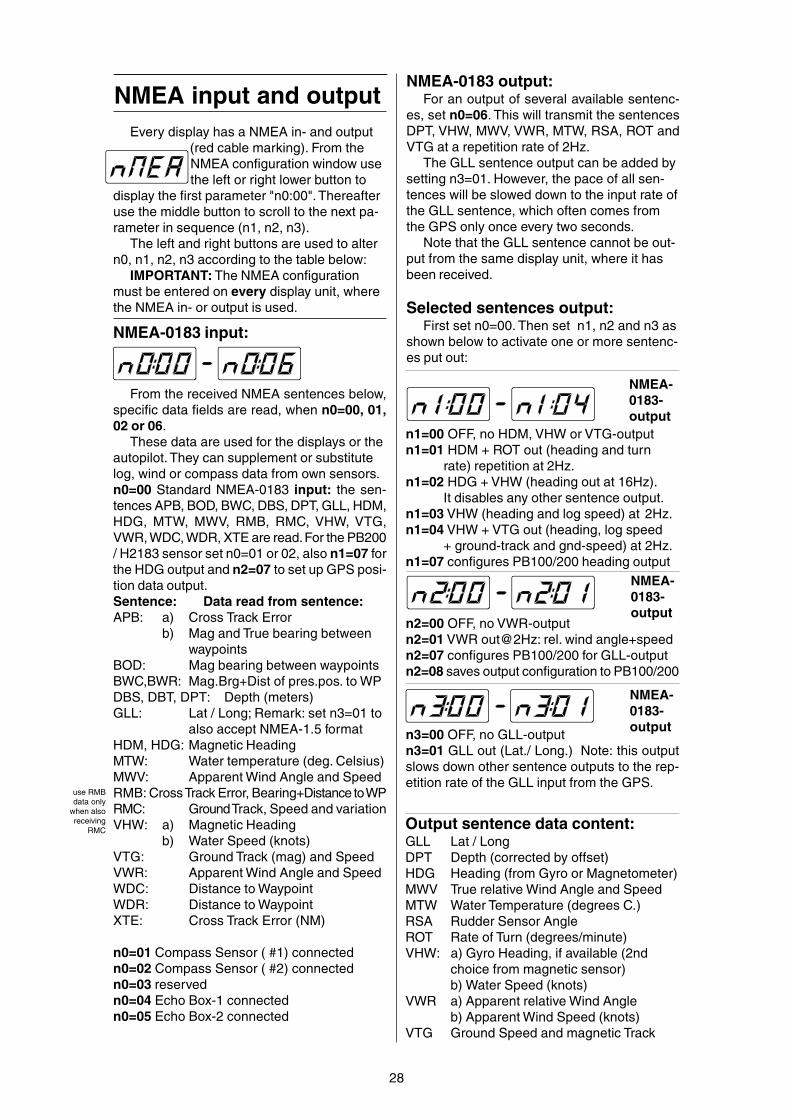
NMEA input and outputEvery display has a NMEA in- and output
(red cable marking). From theNMEA configuration window usethe left or right lower button to
display the first parameter "n0:00". Thereafteruse the middle button to scroll to the next pa-rameter in sequence (n1, n2, n3).
The left and right buttons are used to altern0, n1, n2, n3 according to the table below:
IMPORTANT: The NMEA configurationmust be entered on every display unit, wherethe NMEA in- or output is used.
n3=00 OFF, no GLL-outputn3=01 GLL out (Lat./ Long.) Note: this outputslows down other sentence outputs to the rep-etition rate of the GLL input from the GPS.
NMEA-0183-output
NMEA-0183-output
NMEA-0183-output
n1=00 OFF, no HDM, VHW or VTG-outputn1=01 HDM + ROT out (heading and turn
rate) repetition at 2Hz.n1=02 HDG + VHW (heading out at 16Hz).
It disables any other sentence output.n1=03 VHW (heading and log speed) at 2Hz.n1=04 VHW + VTG out (heading, log speed
+ ground-track and gnd-speed) at 2Hz.n1=07 configures PB100/200 heading output
n2=00 OFF, no VWR-outputn2=01 VWR out@2Hz: rel. wind angle+speedn2=07 configures PB100/200 for GLL-outputn2=08 saves output configuration to PB100/200
NMEA-0183 input:
From the received NMEA sentences below,specific data fields are read, when n0=00, 01,02 or 06.
These data are used for the displays or theautopilot. They can supplement or substitutelog, wind or compass data from own sensors.n0=00 Standard NMEA-0183 input: the sen-tences APB, BOD, BWC, DBS, DPT, GLL, HDM,HDG, MTW, MWV, RMB, RMC, VHW, VTG,VWR, WDC, WDR, XTE are read. For the PB200/ H2183 sensor set n0=01 or 02, also n1=07 forthe HDG output and n2=07 to set up GPS posi-tion data output.Sentence: Data read from sentence:APB: a) Cross Track Error
b) Mag and True bearing betweenwaypoints
BOD: Mag bearing between waypointsBWC,BWR: Mag.Brg+Dist of pres.pos. to WPDBS, DBT, DPT: Depth (meters)GLL: Lat / Long; Remark: set n3=01 to
also accept NMEA-1.5 formatHDM, HDG: Magnetic HeadingMTW: Water temperature (deg. Celsius)MWV: Apparent Wind Angle and SpeedRMB: Cross Track Error, Bearing+Distance to WPRMC: Ground Track, Speed and variationVHW: a) Magnetic Heading
b) Water Speed (knots)VTG: Ground Track (mag) and SpeedVWR: Apparent Wind Angle and SpeedWDC: Distance to WaypointWDR: Distance to WaypointXTE: Cross Track Error (NM)
n0=01 Compass Sensor ( #1) connectedn0=02 Compass Sensor ( #2) connectedn0=03 reservedn0=04 Echo Box-1 connectedn0=05 Echo Box-2 connected
NMEA-0183 output:For an output of several available sentenc-
es, set n0=06. This will transmit the sentencesDPT, VHW, MWV, VWR, MTW, RSA, ROT andVTG at a repetition rate of 2Hz.
The GLL sentence output can be added bysetting n3=01. However, the pace of all sen-tences will be slowed down to the input rate ofthe GLL sentence, which often comes fromthe GPS only once every two seconds.
Note that the GLL sentence cannot be out-put from the same display unit, where it hasbeen received.
Selected sentences output:First set n0=00. Then set n1, n2 and n3 as
shown below to activate one or more sentenc-es put out:
Output sentence data content:GLL Lat / LongDPT Depth (corrected by offset)HDG Heading (from Gyro or Magnetometer)MWV True relative Wind Angle and SpeedMTW Water Temperature (degrees C.)RSA Rudder Sensor AngleROT Rate of Turn (degrees/minute)VHW: a) Gyro Heading, if available (2nd
choice from magnetic sensor)b) Water Speed (knots)
VWR a) Apparent relative Wind Angleb) Apparent Wind Speed (knots)
VTG Ground Speed and magnetic Track
use RMBdata only
when alsoreceiving
RMC

29
Activate NMEA-0183 output:It is important to make the necessary set-
tings on your Nav equipment (GPS, Plotter orPC), to activate the transmission of the routedata towards the Tecnautic autopilot and in-struments. Here are a few hints, for your con-sideration:
** The Tecnautic autopilot and displays usemagnetic bearings, not true bearings. It isrecommended to select also magnetic bear-ings in the setup of your GPS or Plotter.
** Create and activate a route in your Navequipment. Verify that bearing "C", cross trackerror ("r" or "L") and distance to the activewaypoint are displayed on your Autopilot Dis-play. At least bearing and cross track error arerequired to permit the use of the autopilot NAVmode.
** If your Nav equipment permits, activateonly the following output sentences: APB, RMCand WDC. If this selection is not available, useother sentences from the table on page 28 (low-er left), to receive the required data. For exam-ple RMC can be substituted by VTG, APB canbe substituted by (BOD+XTE), BOD by(RMB+RMC), WDC by BWC.
** Select a repetition rate of the sentenceoutput as high as possible on your Navequipment. This might be once per second,depending on your equipment.
** The accuracy of the cross track errordata (XTE) of the Nav equipment can be se-lected on some models. Select three (ormore) decimal digits, if possible.
The autopilot LAND mode must only beused, when at least three decimal digits ofthe cross track error are received. That has tobe verified on the AP-Display. The third deci-mal remains always zero, if it has not beenreceived by the autopilot - do not use theLAND mode in this case.
The autopilot NAV mode can be used withonly two decimal digits received. The resolu-tion of the cross track error is in this case only0.010NM (18.5 meters).
Configure the output of your GPS, Plotter or PC
** The way point switching law has to beset up properly in your Nav equipment. It isrecommended to select (switching to the nextleg) "when abeam", or even "before abeam",where "before" should be set to 5 seconds (or0,005 NM to 0,010 NM).
Without verifying this setting, your Navequipment might switch too early to the nextway point, already far ahead of the active waypoint.
** Curved tracks: If the Nav equipmentdoes not support curved tracks, you may splita curved approach into a series of consecu-tive short tracks. The difference to the nexttrack should not exceed 20 degrees, whenrequiring accurate tracking in Land-Mode.
Contemporary Nav equipment:All modern Nav equipment (GPS, Plotter,
PC) can provide the required basic sentencesfor the autopilot.
NMEA Input at the SERVO-wheel:
From the following NMEA sentences, spe-cific data fields are read. The data are usedfor displaying certain functions and for guid-ance of the autopilot in NAV mode.
The NMEA input is not available at the re-mote steering wheel.
APB: a) Cross Track Errorb) Mag+True bearing between way
pointsBOD: Mag bearing between waypointsBWC,BWR: Mag+True Brg and Dist of
pres.pos. to WPGLL: Lat / LongHDM, HDG:Magnetic HeadingMWV: Apparent Wind Angle and SpeedRMB: Cross Track Error,Bearing+Distance to WPRMC: Ground Track, Speed and variationVHW: a) Magnetic Heading
b) Water Speed (knots)VTG: Mag Ground Track and SpeedVWR: Apparent Wind Angle and SpeedWDC: Distance to WaypointWDR: Distance to WaypointXTE: Cross Track Error (NM)
use RMBdata onlywhen alsoreceivingRMC

Cabling
30
Display Installation
Attention: The cable entrance atthe rear and the plugs must remain
dry.The displays should be mounted inclined
backwards, so that the LCD will be readslightly from below. Otherwise the readabilitywill be degraded at night.
The autopilot display or the compass dis-play respectively, should be mounted withinreach of the helmsman.
Installation has to be made on a flat sur-face to avoid bending the display housing.
!
Bus Cable
BUS
AP Display Log Wind
Bus Power Cable(11...40 Volts)white = Plusbrown = GND
A Bus terminator plug is to be installed at thefar end of the bus cable. Do not installmore than two bus terminators (one may
be fitted within the bus power plug).
SERVO
AP OFF
FBWSteeringWheel
Autopilot
Log Sensor
Log Sensor
Wind Sensor
Wind SensorSensor
Jumbos
Jumbo bus ca-ble (10m)
Bus
Jumbo Displays
Display
Display
Sensor
Bus terminator
!
Bus, Power (blue)NMEA (red)
Electrical SpecificationsCockpit Display: 25...50 mA @ 11...40 Volts
(with illumination: 35...90 mA)Jumbo Display:20...45 mA @ 11...40 Volts
(with illumination: 25...75 mA @ 11..40 Volts)Steering Wheel: 15...40 mA @ 10,5...40 VoltsAutopilot Computer: 35...70 mA @ 9...40 VoltsFlux Gate Sensor: 45 mASonic Heading Gyro: 5 mATecnautic Wind Sensor: 1 mATecnautic Log Sensor: 2 mAEcho-Box w/ Sensor: 50 mAThe lower current is for the higher voltage.
Fuse 2A
Bus, Power (blue)NMEA (red)

31
Compass Sensor andSonic Heading Gyro
Echo Box and Sensor
EchoBox
Alarm Speaker(only Echo-Box-1)
Bus, Power andNMEA0183
Steering Wheel forfixed installation
FBW Steering WheelSteering Wheel formobile installation
Display
The Compass Sensor is connected to theNMEA0183 input of the display.
Attention: use only the bus distributornext to that display unit!
Bus, Power andNMEA0183
SonicHeadingGyro
Display
NMEA0183 Connection:NMEA0183 equipment (like the Compass
Sensor) is connected via the NMEA0183 Con-nection of a display unit. Attention: use onlythe bus distributor next to a display unit!The NMEA-wires are not present in the buscable!
RemoteFBW unit:only Busand Power
Bus
CompassSensor
The Echo-Box is connected via the NMEA-0183 Connection of a display unit.
Attention: use only the bus distributornext to that display unit!
Bus
DepthSensor
NMEA0183
NMEA0183
Sensor input:(Heading-Gyroor Thusterswitches)
Bus, Power andNMEA0183
Bus
Bus
Depth Alarm(Echobox-2)
Display
12345678
12345678 12345678
CAN Buscable:
pin nr. 1..4
NMEA0183cable:
pin nr. 5..8
3-way RJ-45 Dis-tributor
The CAN Bus cable (blue markings) doesnot carry the NMEA0183 wires (5 to 8).
Therefore it is not possible, to connectNMEA0183 equipment (like a Compass Sen-sor or a GPS) to the CAN Bus. NMEA0183devices can only be connected to the distribu-tor that sits directly at a Display Unit.
RJ-45 plug
RJ-45 plug
AnalogSensor
AnalogSensor
123451234512345123451234512345
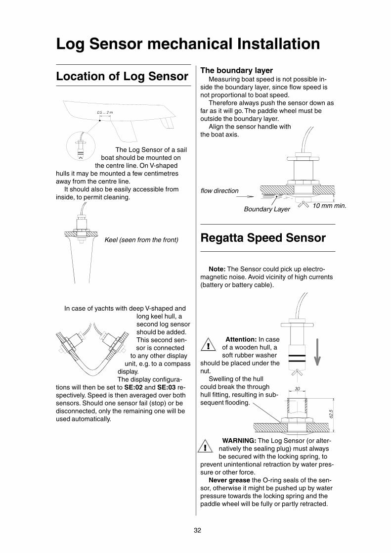
Log Sensor mechanical Installation
32
flow direction
Boundary Layer
The Log Sensor of a sailboat should be mounted on
the centre line. On V-shapedhulls it may be mounted a few centimetresaway from the centre line.
It should also be easily accessible frominside, to permit cleaning.
Location of Log Sensor
62,5
30
Regatta Speed Sensor
Attention: In caseof a wooden hull, asoft rubber washer
should be placed under thenut.
Swelling of the hullcould break the throughhull fitting, resulting in sub-sequent flooding.
Keel (seen from the front)
In case of yachts with deep V-shaped andlong keel hull, asecond log sensorshould be added.This second sen-sor is connected
to any other displayunit, e.g. to a compass
display.The display configura-
tions will then be set to SE:02 and SE:03 re-spectively. Speed is then averaged over bothsensors. Should one sensor fail (stop) or bedisconnected, only the remaining one will beused automatically.
10 mm min.
Note: The Sensor could pick up electro-magnetic noise. Avoid vicinity of high currents(battery or battery cable).
The boundary layerMeasuring boat speed is not possible in-
side the boundary layer, since flow speed isnot proportional to boat speed.
Therefore always push the sensor down asfar as it will go. The paddle wheel must beoutside the boundary layer.
Align the sensor handle withthe boat axis.
WARNING: The Log Sensor (or alter-natively the sealing plug) must alwaysbe secured with the locking spring, to
prevent unintentional retraction by water pres-sure or other force.
Never grease the O-ring seals of the sen-sor, otherwise it might be pushed up by waterpressure towards the locking spring and thepaddle wheel will be fully or partly retracted.
!
!

33
Attention:If the fairing has not asteep leading edge, theboundary layer might bediverted towards the pad-dle wheel!
Fairing (not re-quired for plan-ing boats!)
Installation of a fairing (of non swelling ma-terial) is recommended on displacement hulls(not on planing hulls), to place the paddlewheel outside the boundary layer.
WARNING: The Speed Sensor (or alter-natively the sealing plug) must always besecured by tightening it firmly, to prevent
unintentional retraction by water pressure orother force.
15...
20m
m
water flow
Note: The Sensor could pick up electro-magnetic noise. Avoid vicinity of high currents(battery or batterycable).
Cruise-Speed, PlaningBoat or UniversalSpeed Sensor
Airmar CS4500 Ultra-Sonic Speed Sensor
How the Ultrasonic Speed SensorWorks
The speed sensor uses ultrasonic pulsesto collect echoes from small particles in thewater as they pass under two transducersembedded in the insert. These transducersmonitor the particles in their respectivebeams. As the boat travels through the water,both transducers “view” the same stream ofparticles.
Because it takestime for particles totravel between thetwo transducers, theaft transducer detectsthe particles laterthan does the foretransducer. By mea-suring this time lapse,
the instrument calculates the boat speed. Theultrasonic speed sensor requires particles inthe water to obtain echoes. If the boat is air-borne even for a short time or in highly aerat-ed water, the sensor will measure an incorrectspeed.IMPORTANT: The ultrasonic speed sensormust be in good contact with the water at alltimes for the sensor to function properly.
!

34
!
Compass and Heading Gyro InstallationCompass Sensor
After installation, the sensor has to bealigned parallel to the vessel’s axis. Improperalignment results in a constant heading erroron all headings, e.g. always +4°.
At first align the sensor roughly with themark, to point forward. The next step is tocreate a deviation table by taking relativebearings from deck. Use the vessel as a bear-ing compass for a known object and comparethe magnetic bearing obtained from the chartwith the displayed heading. Use the alignfunction as explained on page 7 and do acompensation cycle only in accordance withpage 7.
!
Install the sensor at a magnetically undis-turbed location. Steady magnetic fields are
allowed, if they do not cause morethan 20° deviation.
Only in cases without a Head-ing Gyro, should the sensor be in-
stalled near the vessels centerof gravity. Horizontal acceler-
ations will be minimal there.During prolonged
horizontal accelera-tions, the sensor willpick up part of thevertical componentof the magneticfield. This cancause largeheading errorsduring roll and
pitch motion inheavy seas.
The cable outlet of theHeading Sensor must pointdownwards and the markingmust be aligned with theforward direction of the boat.
Observe the maximum operating voltage ofthe sensor!
Be aware that the greatest danger lies inmovable magnetic objects like small radios,tools, keys, cell phones, the steering compassor a hand bearing compass. A good compro-mise for above points is often found in a cabi-
net where clothes are stored. Select amid level, not at the floor and not just
under deck. An anchor chain on deck couldmake your autopilot turn sharply! Also batter-
ies and their leads can producestrong magnetic fields when thebattery is charged or discharged; a
distance of two meters fromthese sources is adequate.
On steel hulls, an abovedeck installation is necessary.
The sensor cable may beextended as necessary.
Sonic Heading GyroThe TECNAUTIC Sonic Gyro is a strap down
heading gyro with a so called vibrating gyro ele-ment.
When connected to a properly configured dis-play unit, all compass displays in the system willdisplay the Gyro Heading (see compass andautopilot functions).
The Gyro Heading is neither fluctuating norhas it acceleration errors.
The Compass Sensor or a GPS is still need-ed to prevent long term drifting of the gyro.
Fluctuations of the Magnetic Heading Sen-sor have no effect on the Gyro Heading. The Son-ic Heading Gyro needs no damping and trans-mits all heading changes instantly.
For the autopilot the heading is transmittedwith a 0.1 degrees resolution every couple milli-seconds.
Installation:The Sonic Gyro must be
mounted vertically on a wallwith no or little vibration.
Attention: temperature changes can affectthe accuracy of the heading. Thereforechoose a location where temperatureis not changing rapidly, e.g. inside a
closet, and protect it from sunshine or otherradiated heat.
H2183
PB200

35
The Wind Sensor must be installed at theforward end of the mast top and its arm mustpoint forward, so as to give the most accuratereadings, when close hauled or reaching.
The direction of air flow is neverthelessaltered by the presence of the sail under-neath. To avoid the resulting inaccuracies oftrue wind direction, speed and VMG, the windsensor can be mounted on a small mastabout 2 m (7 feet) above the mast top.
The mast cable should be held at the masttop with a cable tie, in order to relief the plugfrom any strain. The cable must not come incontact with moving halyards.
Operating information: when powering upthe wind display, the anemometer wheel isdriven electrically for a period of two seconds,to break any eventually present cob webs.
Through deck connector: For easy mastremoval, a sealed connector may be mounted.Only gold plated contacts are allowed, be-cause of the low signal level. Silver platedcontacts will also work for some time.
deck
mast
Sensor arm may be bent
forward
Through deck connector (fixed)
contact- leadNr. color signal:
1 white +5 Volts2 brown 0 Volts3 yellow wind angle4 green wind speed
Connector installation:
Sealed through deck connector (flying)(see page 49 for plug installation)
Tecnautic Windsensor(Use separate instructions for thePB200 Sensor)

Echo-Box-1 and -2
36
The Echo-Box should be mounted at a dryand accessible location.
Echo-Box
SensorConnection
To DepthDisplay
Language SelectionEchobox-1
ED
MF
E...english announcementD...german announcementM and F...not used
Switch
Sensor-Frequency Se-lection Echobox-1
Selector Switch
The Echo-Box1 can work with depth trans-ducers of various frequencies within the rangeof 140 kHz to 160 kHz. Switch position # 8 isthe lowest frequency, # 7 is the next higherone, and so on, and # 9 is the highest fre-quency.
In case the depth transducer is replaced,the new number must be selected on theswitch. It can be read from a tag on the cableon all Tecnautic-supplied sensors.
An unknown sensor frequency can befound by selecting a switch position with whichthe echo sounder would work satisfactory athigher depth values.
To Speaker
BUS
E-6-S
TEST
Lead Lead TerminalNr. Color Signal Number inin the plug Echo-Box1 (white) white +10..28V 22 (brown) blue GND 13 (green) cyan CAN+ .... do not connect!4 (yellow) magent. CAN- .... do not connect!5 (grey) white IN-B (to Box) 46 (pink) orange IN-A (to Box) 57 (blue) brown OUT-B 18 (red) red OUT-A 8
1 2 3 4 5 6 7 8
two leads tospeaker
8 lead flat ca-ble to DepthDisplay
Inside Echo-Box
Electrical ConnectionEchobox-1
Speaker InstallationEchobox-1
The speaker should be placed into a cabi-net in such a way, that the speaker is sealedfrom the rear side. This is important for goodsound quality. Without such a sealed cabinet,the sound will be distorted and rather weak.

Echo-Sensor Installation
Location of the DepthSensor
37
15...
20m
m
FairingFlow DirectionAttention:
the fairing mustnot be too flat; otherwise theboundary layer would be deflectedonto the transducer face!
Non-aerated (bubble free)water must flow across thetransducer face at all
speeds if good depth sound-ing performance is to be
achieved. The transducer should be located,where the following conditions can bemet:
tightening from inside the hull.7. The transducer transmits also some en-
ergy sideways into the hull. If the returningechoes from inside the hull are strong enoughto be received, an acoustic isolation betweenhousing and hull will be required. Any soft(porous) material may be used.
1. On sailboats the transducer shoud bemounted where the acoustic beam will not beshaded by the keel. A spot forward of a finkeel is usually best. Try to find an accessiblespot with a minimum dead rise angle.
2. On displacement hull power boats (e.g.trawlers), the transducer should be mountedamidships, relatively close to the keel (center-line of hull).
3. On planing power boat hulls, the trans-ducer should be mounted well aft and close tothe keel to insure that the transducer is incontact with the water at higher boat speeds.If the vessel is capable of speeds greater than25 knots, you may wish to review installationlocation and operational results on similarboats before proceeding.
4. Never position a depth transducer direct-ly behind shaft struts, fittings and paddlewheel speed transducers, since the turbu-lence can adversely affect depth transducerperformance.
5. On I/O’s (stern drive) transducer mount-ing close to the engine(s) usually yields goodresults. On inboards always mount the trans-ducer well ahead of the propeller(s). Turbu-lence from props seriously degrades trans-ducer performance. Make sure transducer isnot shaded by the prop shaft(s).
6. It is very important that the mountinglocation have reasonable access from insidethe vessel since the transducer will require
8. At speeds above 10 kts the turbulentboundary layer will provide a shield for thetransmitted and received signals, preventingany echo sounder operation. To overcomethis, a fairing of non swelling material shouldbe fitted, to place the transducer face belowthe boundary layer.
Maintaining the DepthTransducer
Antifouling paint: If the vessel is kept insaltwater, sea growth can accumulate rapidlyon the transducer face and seriously reduceperformance in a matter of weeks. It is recom-mended that the external face of the transduc-er be coated with an antifouling paint. Useonly mineral spirits based antifouling paint. Donot use Ketone based paints since they attackthe potting materials used in the transducer. Iffouling does occur, use a stiff brush or puttyknife to remove growth. Wet sanding of fouledtransducer face is permissible with NR. 220 orfiner grade type emery paper (use plenty ofwater).

38
Provide a provisionalpatch of water at the de-sired location
Plastic hull (not to bevery thick)
Remove air bubbles!
Remove paint and insulation
Minimum gap 1 mm
Not more than 20 mmfrom the hull!
No bubbles under thetransducer!
2. Choose a location where the hull is notvery thick. Check also points 1) to 7) listedunder “location of depth transducer”. They areequally valid for a within hull installation.
3. The third step is toinstall the housing at thelocation determined. Selecta marine bedding / caulk-ing compound e.g. Sika221. Install vertically andfill with water or oil. Thetransducer face must be in
the fluid even when thevessel is heeled.
Standard installationwith through hull fitting
Advantage of a through hull installation is,that there are no doubts if and how well thesound waves will pass through the hull (com-pared to a within hull installation).
There are a few points to be considered forthe through hull installation:
1. The sensor shouldbe mounted verticallyand not inclined, nei-ther sideways nor for-ward or aft. If the hullis not level, a fairing
has to be fittedoutside andinside.
2. In case ofa wooden hull or
wooden fairings, useonly a metal through hull
fitting.Swelling of the wood may over stress the
plastic housing. Also hauling the ves-sel may over stress and crack the
housing.
3. Do not expose a plastic through hulltransducer to solvents. The
housing might crack andleak.
4. In case of a coredhull, make sure that nowater can enter into thecore. This might require
bonding of a tubeto the inner andouter hull, beforeinstalling the trans-ducer housing.
5. Do not use metal hous-ings on metal hulls. Electrolytic corro-sion will occur.
Always tighten the lid firmly!
!
!
!
Within hull installationThis kind of installation is only possible on
compact non porous plastic hulls.It is not recommended for boats faster than
10 kts.Steps of installation:
1. The boat must be in the water. A "sonicwindow" has to be found in the hull, wherethe echo sounder works! The first step is tofind a place where the sound waves can pen-etrate the hull without losses. This test is ab-solutely required, because there is no otherway to find out. The vessel must be in the wa-ter at a place where echoes are not absorbedby mud or other soft ground. This test can
best be done with the vesselunder way over different seabottom.
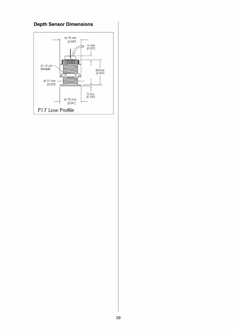
39
Depth Sensor Dimensions

BB
open? open
closed
40
Autopilot Connection
A) reversible ruddermotor (mechanical orhydraulic)
B) non reversible pumpwith speed regulationand switch-over valve
Valve (3,4) orclutch or cooling fan(1,2) orBow or Stn Thruster:L=1,2 R=3,4 (seepage 23 / A8)
Rudder AngleSensor
closed? open
Rudder AngleSensor
Motor
Valve(leftrudder)
Valve(rightrudder)
Jumper 1 may be closed to reverse themeasured rudder angle and to activate theTILLER-BUTTON on AUX-2
a) Motor (7=+, 8= -)b) Bow thruster relaysignal left .... 7=+signal right .. 8=+common 6=minus
Battery12 to 24 V
open
Tiller Button(AP ON-OFF)
Jumper-1 requiredclosed
cyan
(3)
Short leads to batteryand motor. Use 2.5 mm2
(AWG12) up to 3 m (10')length. Heavier gaugefor longer leads.
Short leads to batteryand motor. Use 2.5 mm2
(AWG12) up to 3 m (10')length. Heavier gaugefor longer leads.
Autopilot Com-puter
(DRIVEBOX)
1 2 3 4 5 6 7 8Rudd.Angle
CAN-Bus+ NMEA
Jumper 1 Jumper 2 Jumper 3
Jumper 4
Battery12 to 32 V
M
Jumper 4
Jumper 1 Jumper 2 Jumper 3
1 2 3 4 5 6 7 8
M
Autopilot Com-puter
(DRIVEBOX)
AUX-1 AUX-2
blue
(2)
Rudd.Angle
CAN-Bus+ NMEA
AUX-1 AUX-2
+
Jumper 1 may be closed to reverse themeasured rudder angle and to activate theTILLER-BUTTON on AUX-2
Docking-Mode with-out FADEC:connect AUX-1 to theREVERSE-signal ofits associated engine(microswitch closesblue/2 to cyan/3when in REVERSE)
Docking-Mode with-out FADEC:connect AUX-1 to theREVERSE-signal ofits associated engine(microswitch closesblue/2 to cyan/3when in REVERSE)

BB
41
D) with current con-trolled servo valve
These valves have virtually no hysteresisand the hydraulic flow has a linear character-istic
ShutoffValves
open?
ServoValve
Rudder AngleSensor
Valve filter (forservo valve)
Battery12 to 24 V
closed
MotorRelais(Option)
Battery leads:2 x 2.5 mm2
(AWG12)
C) continuous pumpwith switch-over valveorcurrent controlled (nonlinear) proportional valve
closed? closed
Rudder AngleSensor
a) contin. running pumpb) Bow- or Stn Thrusterrelay (see page 23 / A8)
Valve(leftrudder)
Valve(rightrudder)
Battery12 to 24 V
Short leads to bat-tery and motor. Use 2.5mm2 (AWG12) up to 3m (10') length. Heaviergauge for longer leads.
a) open with switch over valveb) closed with proportional valve closed
+M
1 2 3 4 5 6 7 8
Autopilot Com-puter
(DRIVEBOX)
Jumper 1 Jumper 2 Jumper 3
Jumper 4
Jumper 1 Jumper 2 Jumper 3
Jumper 4
1 2 3 4 5 6 7 8
Autopilot Com-puter
(DRIVEBOX)
Rudd.Angle
CAN-Bus+ NMEA
AUX-1 AUX-2
++
Rudd.Angle
CAN-Bus+ NMEA
AUX-1 AUX-2
Jumper 1 may be closed to reverse themeasured rudder angle and to activate theTILLER-BUTTON on AUX-2
Jumper 1 may be closed to reverse themeasured rudder angle and to activate theTILLER-BUTTON on AUX-2

B
42
Trim Flap ElectronicsWith switch over valve
left flap anglesensor
up up
openopen
open
Battery12 or 24V
Jumperleft
Jumperright
Battery leads:2 x 2.5 mm2
downdownValve left
flapValve
right flap
right flap anglesensor
open
Jumper 1 Jumper 2 Jumper 3
Trim Computer(TRIM BOX)
2 3 4 5 6 7 8
FlapAngle
CANBus
CANBus
Jumper 4
B
E) with voltage con-trolled servo valve
The output signal is suitable for proportion-al valves with up to 20% hysteresis (e.g Dan-foss Type PVEM).
closed?
Rudder AngleSensor
Battery12 to 24 VUDC
closed
Battery leads:2 x 0.5 mm2
(AWG20)
closed
Jumper 1 Jumper 2 Jumper 3
Jumper 4
1 2 3 4 5 6 7 8
Autopilot Com-puter
(DRIVEBOX)
Rudd.Angle
CAN-Bus+ NMEA
AUX-1 AUX-2
Output Signal: UDC/2+/- 25%UDC (outputimpedance = 1kOhm)Set A5=08, A5*=01,A0*=01; use A4*=0/1for inverse signal; useA1=0/1 to adjust idlesignal by 1% up
Jumper 1 may be closed to reverse themeasured rudder angle and to activate theTILLER-BUTTON on AUX-2
Docking-Mode with-out FADEC:connect AUX-1 to theREVERSE-signal ofits associated engine(microswitch closesblue/2 to cyan/3when in REVERSE)

43
Rudder Angle SensorInstallationStandard version for mounting onthe cylinder piston rod
ATTENTION: The hook length must beadjusted so as not to interfere with the cylin-der, when the piston is fully retracted!
To adjust the hook length, proceed as fol-lows:
1. Remove the lid on top of the Sensor2. Unscrew the hook3. Adjust the hook length and tighten the
hook screws4. Close the lid
The hook must be bent so as to guaranteea firm grip of the piston rod, even when it ismoving vertically! There must be absolutelyno play.
WARNING: make sure the hook does notinterfere with the rudder arm at full rudderdeflection!!!
The sensor is supplied with a hook. Thehook is properly bent for a piston rod of 16mm (5/8") diameter.
A hole (6,5 mm / 2/8" diameter and 10 mm/ 3/8" deep) should be drilled along the axis ofthe bolt. A second hole with a 3 mm (1/8")thread is required to fix the shaft of the poten-tiometer in the bolt. For different conditions,the wire hook may be bent as required.
If the linear drive unit has been supplied byTECNAUTIC, the bolt with properly drilledholes is provided by the factory.
The rudder anglesensor must pick upthe rudder move-ment without anyplay.
Piston Rod of hy-draulic cylinder
Checking the Sensor after the in-stallation and setup procedure hasbeen completed
Do not proceed with this test before com-pleting the initial installation and setup (p.22)!
Switch on the SERVO mode, if anelectronic steering wheel is installed and turnthe wheel to the middle position.
Or, if there is no electronic steering wheelavailable, have the boat moored firmly, so asnot to change its heading. Place the rudderamidships and engage the autopilot HDGmode. Verify the displayed heading to be sta-ble, before engaging the autopilot.
The rudder should be steady at this stage.
Now try to apply very light sideways forcewith your finger tip onto the hook of the rudderangle sensor. If there is play, the rudder willmove. Eliminate the play!
Play leads to rudder oscillations and inac-curate steering.
Conventional Rudder Sensor Instal-lation
In case of an existing rudder actuator, itmight be easier, to install the sensor in a con-ventional way. Tecnautic recommends its
"sealed rudder sensor"(part nr. 23 00 03) forthat purpose.
There is no require-ment on the orientation of the sen-
sor. The sensor arm A and the effectivearm B at the rudder must be of equal length.Only with stern drives A can be bigger than B,to achieve larger rudder deflections.
Symmetric conditions are required in thecase of two independent rudders or sterndrives.
NOTE: there must be a 90 degrees anglebetween the arm and the connecting rod,when the rudder is centered.
A
Make sure: A = B
B
Rudder Centered:
44
Linear Drive Unit: InstallationElectro-hydraulic Linear Drive for Tiller-Steeringand mechanical Wheel-SteeringGeometric Situation
Fist of all, the geometric layout must be de-termined. The support with the joint at the rearcylinder end will be attached to the hull struc-ture. The piston rod will be connected to the rud-der arm with a bolt.
The cylinder may be mounted in front or be-hind the rudder shaft, the sense of rotation doesnot matter.
The piston rod must move in the same planeas the rudder arm. This is achieved by aligningthe cylinder support mounting surface perpen-dicular to the rudder shaft. The length of the rud-der arm "F" can be taken from the table nextside. The lateral distance "G" should be about(0.86...0.90)R.
The required length of the autopilot tiller armcan be determined after measuring the vessels'maximum rudder deflection: shortly before eachcylinder end position, full starboard or port rud-der should be reached. Do not use the cylinderas the mechanical rudder limiter.
The standard rudder angle sensor is provid-ing the rudder angle output signal for an angu-lar range of +/- 45 degrees.
The maximum available rudder deflectionunder autopilot or servo steering can bechanged. See "Autopilot Function / Initial Oper-ation" or "Control Wheel Function / Initial Oper-ation".
Installation HintsThe autopilot tiller arm must be locked onto
the rudder shaft by a key or wedge. Transmis-sion of the torque by friction alone requires avery heavy design of the arm.
In case a rudder quadrant is present, the pis-ton rod should be attached to it, eliminating theneed for a separate tiller arm.
The drive installation must be very rigid andstiff. Especially the distance between ruddershaft and rear cylinder mount must not changeunder the load of the cylinder force.
Installation1. Replace the transport tank cap with the
cap from the box; it has a breathing hole!2. Purge air now according procedure below!
Then remove the rudder angle sensor from thetiller arm bolt and keep it hanging on the cylin-der rod with its hook. Then tighten the tiller armbolt and the cylinder support screws. Reinsertthe rudder angle sensor into the tiller arm bolt,but do not lock its shaft with the M3 lock-
Purging the Hydraulic SystemBefore installation, it is necessary, to purge
air from the hydraulic cylinder and to add auto-matic transmission fluid to the hydraulic tank,but not more than half full. The "shipping" tankcap has to be replaced with the regular one,with a breathing hole, before moving the pis-ton and use of the drive.
For verification connect the Bypass Valve tothe battery. Even under great force, the pistonrod cannot be moved more than 1 mm (1/32in.) if air has been purged completely.
The following symptom will always requirepurging of the system:
If the rudder can be moved mechanically (bydirect force onto the rudder), when the autopi-lot or Servo Steering is engaged. Exception: verysmall movements of the piston (less than 1 mm)are permitted.
To purge air: disconnect the rudder and thesensor. Switch on SERVO or AP and turn thesensor shaft slowly until the piston hits the cyl-inder end firmly. Then hit the other end firmly.Repeat 10 times with full rudder speed.
!
ing screw yet. This will be done during "initialoperation".
Fill up the hydraulic tank half way (use auto-mobile automatic transmission fluid available atgas stations). Never use "hydraulic fluid"!Installation of detached pumps
The pump must be located higher than thecylinder. Air from the cylinder must be able toascend to the pump. The reservoir must be thehighest point in the system.Adjustment of pump flow
Some pumps permit mechanical adjustmentof the pump flow. Always select the maximumpump flow (factory setting).Rudder Speed Selection
A high maximum rudder speed is desirablefor good autopilot function. However it is a mustfor Servo Steering. A low maximum rudderspeed can lead to heading oscillations.Danger! Therefore the maximum availablerudder speed (pump flow) should alwaysbe selected. The Tecnautic Drive-Box is regu-lating the pump speed electronically and reduc-ing rudder speed automatically, whenever nec-essary.

45
Angle (degrees) 30 32 35 37 40 42 45 47 50 52 55Throw mm Radius (mm)150 150 141.5 130.8 124.6 116.7 112.1 106.1 102.5 97.9 95.2 91.6155 155 146.2 135.1 128.8 120.6 115.8 109.6 106 101.2 98.3 94.6160 160 151 139.5 132.9 124.5 119.6 113.1 109.4 104.4 101.5 97.7165 165 155.7 143.8 137.1 128.3 123.3 116.7 112.8 107.7 104.7 100.7170 170 160.4 148.2 141.2 132.2 127 120.2 116.2 111 107.9 103.8175 175 165.1 152.6 145.4 136.1 130.8 123.7 119.6 114.2 111 106.8180 180 169.8 156.9 149.5 140 134.5 127.3 123.1 117.5 114.2 109.9185 185 174.6 161.3 153.7 143.9 138.2 130.8 126.5 120.8 117.4 112.9190 190 179.3 165.6 157.9 147.8 142 134.4 129.9 124 120.6 116195 195 184 170 162 151.7 145.7 137.9 133.3 127.3 123.7 119200 200 188.7 174.3 166.2 155.6 149.4 141.4 136.7 130.5 126.9 122.1205 205 193.4 178.7 170.3 159.5 153.2 145 140.2 133.8 130.1 125.1210 210 198.1 183.1 174.5 163.4 156.9 148.5 143.6 137.1 133.2 128.2215 215 202.9 187.4 178.6 167.2 160.7 152 147 140.3 136.4 131.2220 220 207.6 191.8 182.8 171.1 164.4 155.6 150.4 143.6 139.6 134.3225 225 212.3 196.1 186.9 175 168.1 159.1 153.8 146.9 142.8 137.3230 230 217 200.5 191.1 178.9 171.9 162.6 157.2 150.1 145.9 140.4235 235 221.7 204.9 195.2 182.8 175.6 166.2 160.7 153.4 149.1 143.4240 240 226.4 209.2 199.4 186.7 179.3 169.7 164.1 156.6 152.3 146.5245 245 231.2 213.6 203.6 190.6 183.1 173.2 167.5 159.9 155.5 149.5250 250 235.9 217.9 207.7 194.5 186.8 176.8 170.9 163.2 158.6 152.6255 255 240.6 222.3 211.9 198.4 190.5 180.3 174.3 166.4 161.8 155.6260 260 245.3 226.6 216 202.2 194.3 183.8 177.8 169.7 165 158.7265 265 250 231 220.2 206.1 198 187.4 181.2 173 168.1 161.8270 270 254.8 235.4 224.3 210 201.8 190.9 184.6 176.2 171.3 164.8275 275 259.5 239.7 228.5 213.9 205.5 194.5 188 179.5 174.5 167.9280 280 264.2 244.1 232.6 217.8 209.2 198 191.4 182.8 177.7 170.9285 285 268.9 248.4 236.8 221.7 213 201.5 194.8 186 180.8 174290 290 273.6 252.8 240.9 225.6 216.7 205.1 198.3 189.3 184 177295 295 278.3 257.2 245.1 229.5 220.4 208.6 201.7 192.5 187.2 180.1300 300 283.1 261.5 249.2 233.4 224.2 212.1 205.1 195.8 190.4 183.1305 305 287.8 265.9 253.4 237.2 227.9 215.7 208.5 199.1 193.5 186.2310 310 292.5 270.2 257.6 241.1 231.6 219.2 211.9 202.3 196.7 189.2315 315 297.2 274.6 261.7 245 235.4 222.7 215.4 205.6 199.9 192.3320 320 301.9 279 265.9 248.9 239.1 226.3 218.8 208.9 203 195.3
The tiller radius "F" (on the right side) is fora maximum rudder angle of 35 degrees. Usetable below for different angles.
Rudder Arm Radius as a function of piston throw and rudder angle:
Type V2H32S, V2H40Sand V2H50S(Lecomble & Schmitt)

46
The electric pump is normally mountednear the steering cylinder. Three hydraulichoses are required, to connect it to the steer-ing system. The wheel pump must have checkvalves installed or the Steering Wheel willstart turning, when pressure builds up fromthe electric pump. Some wheel pumps don'thave check valves; they require installation ofa check valve block next to the wheel pump.
Boats with two hydraulic steering wheelshave check valves already installed.
After making the required hydraulic con-nections, the system needs to be filled with oil.Automatic transmission fluid for automobileshas to be used. Purge air according instruc-tions for the steering system. Eventually re-peat purging after brief operation of the auto-pilot or Servo Steering. Some autopilot pumpmodels allow purging at the pump itself. Incase of pressurised hydraulic systems, do notexceed the prescribed air pressure.
Adjustment of pump flowSome pumps permit to adjust mechanically
their flow, to vary the maximum available rud-der speed. Always select the maximumpump flow.
Maximum Rudder Speed SelectionA high maximum rudder speed is desirable
for good autopilot function. However it is amust for Servo Steering. A low maximum rud-
der speed can lead to heading oscillations.Danger! Therefore the maximum avail-
able rudder speed should always beselected. The Tecnautic Drive-Box is
regulating the pump speed electronically andreducing rudder speed automatically, whenev-er necessary.
WARNING:If the autopilot does not keep the selected
heading (in HDG mode), the first thing tocheck is the stiffness of the hydraulic system.
Switch off the autopilot and the electronicservo steering. Then apply physical force ontothe rudder with the emrgency tiller. Do NOT(!)use the hydraulic helm. The piston should notmove more than 1 mm (1/32") at maximum.
1. Verify that there is no air in theram:
Disconnect the pump motor from the Drive-box, but keep the Bypass Valve connected.
Engage the autopilot now: the valve willclose and lock the rudder. Try to move yourhelm or tiller with moderate force to Star-board, then reverse your force to Port. Thepiston rod should not move more than 1 mm(1/32 in.) if air has been purged completely.Otherwise you have to purge the air from thecylinder.
2. Purging the last bit of air:Important: keep the purge valves closed (at
the ram and the pump), do not use them.Disconnect the rudder sensor mechanically
from the rudder, so it will not move, when therudder moves.
Further, we must be able to work the pistonto the very end of the cylinder, both sides.This will normally necessitate detaching thepiston rod from the tiller arm or quadrant. Orelse we might hit a mechanical rudder stop,before the cylinder reaches its limit.
Rotate the sensor shaft so as to get a cen-ter position on the LED of the autopilot display.
With the motor and the valve reconnectedto the Drivebox, engage the autopilot in Head-ing Mode (make sure the heading does notchange and the boat is moored firmly).
Turn the sensor shaft about three degreesto either side, this will start the pump. Don'tturn the sensor too far or the autopilot willdisengage. Stay there until the piston hits thecylinder end firmly. Then turn the sensor shaftquickly back to reverse the pump, and staythere, until the piston hits the other end of theram. Repeat that 10 times with full rudderspeed.
3. Verify again according step 1above!
How to purge a LinearDrive after installation
Hydraulic SteeringPump Installation
!

47
Eventual secondSteering Station
Check ValveBlock
AutopilotPump
Wheel pump with-out check valves
Cylinder
wider separationtowards cylinder
Installation of a checkvalve block
Check valves have been already installed orintegrated into the wheel pumps in the case oftwo Steering Stations.
Important!The autopilot pump must be connected to
the hydraulic tank through a Return Line. Thehydraulic tank is normally inside the helmpump.
To function properly, the autopilot pumpneeds to receive at least slight fluid pressurefrom the return line. A tank location of 3 ft(1m) above the autopilot pump will providesufficient pressure to the pump.
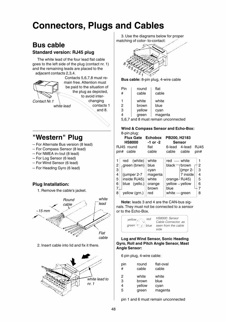
48
Connectors, Plugs and Cables3. Use the diagrams below for proper
matching of color- to-contact:
76543
8
21
white lead tonr. 1
2. Insert cable into lid and fix it there.
Standard version: RJ45 plugBus cable
Contact Nr.1white lead
"Western" Plug-- For Alternate Bus version (8 lead)-- For Compass Sensor (8 lead)-- For NMEA in-/out (8 lead)-- For Log Sensor (6 lead)-- For Wind Sensor (6 lead)-- For Heading Gyro (6 lead)
Plug Installation:1. Remove the cable's jacket.
~15 mm
Roundcable
Flatcable
whitelead
Bus cable: 8-pin plug, 4-wire cable
Pin round flat# cable cable
1 white white2 brown blue3 yellow cyan4 green magenta5,6,7 and 8 must remain unconnected
Wind & Compass Sensor and Echo-Box:8-pin plug:
Flux Gate Echobox PB200, H2183HS8000 -1 or -2 Sensor
RJ45 round flat 6-lead 4-leadpin# cable cable cable cable
1 red (white) white red white2 green (brwn) blue black brown3 cyan (jmpr 2-4 (jumper 2-7 magenta 7 inside5 inside RJ45) white orange RJ45)6 blue (yello.) orange yellow yellow7 brown blue8 yellow (grn.) red white green
Note: leads 3 and 4 are the CAN-bus sig-nals. They must not be connected to a sensoror to the Echo-Box.
Log and Wind Sensor, Sonic HeadingGyro, Roll and Pitch Angle Sensor, MastAngle Sensor:
6 pin plug, 4-wire cable:
pin round flat-oval# cable cable
2 white white3 brown blue4 yellow cyan5 green magenta
pin 1 and 6 must remain unconnected
The white lead of the four lead flat cablegoes to the left side of the plug (contact nr. 1)and the remaining leads are placed to the
adjacent contacts 2,3,4.Contacts 5,6,7,8 must re-main free. Attention mustbe paid to the situation of
the plug as depicted,to avoid inter-
changingcontacts 1
and 8.
yellow red
green blue
HS8000: SensorCable Connector, asseen from the cableside
1
24
3
RJ45pin#
12345678

max. 1mm
4. Trim the leads with a sharp knife.
pincers
Pin lead# color signal: data:
5 white out-B from display6 blue out-A from display7 cyan in-B to display8 magenta in-A to display
The NMEA Input of the display unit canreceive signals conforming to NMEA-0183-V1.5 and V.2.0
The NMEA Output signal conforms toNMEA-0183 Version 2.x (symmetric signal)with a 5 Volts differential amplitude.
Therefore both version 1.5 and 2.x receiv-ers can be connected.
NMEA-CableRJ45 Plug
Pin #1
External NMEA data (from a GPS or otherequipment) are received on pins 7 and 8 ofthe display bus connector. Pins 5 and 6 areused for transmitting NMEA data from thedisplay to other equipment.
The white lead of the 4-lead flat cable con-nects to pin 5, the magenta lead to pin 8. Pins1 through 4 must remain unconnected. Mind
the correct position of the plug,to make sure that pin 1 andpin 8 are not mixed up.
white lead ontopin #5
49
5. Place the lid onto the housing until thelatches snap in (use pincers).
Cylindrical 4-pin plugFor Log Sensor and Wind Sensor
Pin housing (seen from cable en-trance):
Marking
21
34
Socket housing (seen from cableentrance):
Marking
34
21
Pin housing
Sealing
Socket housing
Pin contact
Socket contact
Sealingplug
Pin contacts are always located on thesensor side, socket contacts on the displayside.
Pin round flat-oval# cable cable
1 white white2 brown blue3 yellow cyan4 green magenta
Pin round flat-oval# cable cable
1 white white2 brown blue3 yellow cyan4 green magenta
1 (white)FBW Steeringwheel
Plug on spiral cabel,seen from cable side
2 (blue) 3 (cyan)
4 (magenta)
Mobile Fly-By-WireSteering Wheel
For single pole (Version 1.5) data receiv-ers, you should connect Tecnautic"Out-A" to"Data-IN" of the receiver. All equipment musthave a common supply GND in this case.

Autopilot FAIL messageReading last disconnect reason ormode change reason:
In case of an automatic AP disconnect, thereason will be displayed automatically as a"FAIL" code on the AP display(s). To read itagain later, or to read the reason for an auto-matic mode change, press and hold the OFF-button for 3 seconds.
For older display units, select the "Config"mode on a display unit (any unit in the sys-tem). Press the right button to read out thelast FAIL code of the DRIVE BOX. Note: whenswitching off the bus power, any code storedinside the diplay units will be lost; a randomnumber (e.g. 33) will be displayed after power-ing up again, until a code is received from theautopilot.01 OFF due to over current02 OFF due to over temperature03 OFF due to rudder sensor extreme04 OFF: CB on DRIVEBOX has dropped05 Battery voltage low! (no AP disconnect)06 OFF due to Gate Voltage too low07 OFF due to 1/4-sec over current limit08 One of two(!) rudder sensors is inoper.!12 OFF: AP disconnected by tiller button13 7474 OFF (instant short circuit cut off)14 OFF due to sensor data missing15 OFF due to 4-second over current limit16 OFF or HDG mode due to interrupted
data stream from CW17 OFF due to drive current > 45A18 a) Change from APP wind mode to HDG
mode due to missing APP wind data, orb) Change from TRU wind mode toHDG mode, due to missing TRU windand APP wind or rate of turn data
19 Change from TRU to APP wind modedue to missing TRU wind data
21 Change from HDG mode to TRU windmode due to missing HDG data
22 OFF from HDG mode due to missingHDG (and APP wind or turn rate) data
23 OFF from APP wind mode due to miss-ing HDG and turn rate data
24 Change from TRU to APP wind mode orto OFF-mode due to missing HDG data
25 AP OFF due missing data from externalrudder angle sensor
26 AP OFF due to switching SERVO wheelto the 90 degrees thruster mode
27 Change from NAV mode into HDG modedue to loss of NAV data.
28 OFF or HDG mode on SLAVE-AP dueto failure of MASTER-AP (dual AP's)
29 Change from TRK to HDG mode due tolow Ground Speed (< 0.5 kts)
50

51
Throttle Station SetupEntering the SETUP mode: press and hold
the left and right button. Then, while holding theleft and right button, press the middle buttonfour times briefly and release all buttons. Thisprocedure would also unlock a locked unit.
The red LED (only) will come on, indicatingsetup step 1 (P1) of the station.
Step P1: By pressing AP, the maximumrudder deflection is set to the actual rudder an-gle. Press SERVO briefly to advance to step 2,or press THR to exit the setup mode.
Step P2: (reserved function) Press SERVObriefly to advance to step 3, or press THR to exitthe setup mode.
Step P3: Press AP (the middle button) brieflyand listen to the number of beeps. Press APagain to increase the number of beeps. P3 se-lects the connected equipment (toggles or gyro).
When finished, press SERVO briefly to ad-vance to step 4, or press THR to exit the setupmode.
Step P4: P4 calibrates the throttle potentiom-eter after connecting it for the first time to thisFBW-unit or after reinstalling it.
When finished, press and hold SERVO toadvance to step 5a, or press and release theSERVO button to advance to step 5b, or pressTHR to exit the setup mode.
Step P5a: P5a locks the FBW unit, when theAP button is pressed before the SERVO buttonhas been released.
Step P5b: (no function) press SERVO brieflyto advance to step 6, or press THR to exit thesetup mode.
Step P6: P6 sets the illumination group num-ber for the unit. Press the middle button repeat-edly to select the desired number. Standardsetting is P6=1 (one beep), for group number 1.
Press SERVO briefly to advance to step 7, orpress THR to exit the setup mode.
Step P7: P7 sets the throttle lever type.Press the middle button to select the throttlelever type of this station. Setting the wrongnumber is dangerous and may cause unwant-ed switchings.
Press SERVO briefly to advance to step 0, orpress THR to exit the setup mode. Step 1 fol-lows again after step 0.
Step P0: P0 defines the right button function:P0=1: THR-button or P0=2: OFF-button (turnsoff the AP and SERVO-wheel).
Whenever unsure about the present stepnumber, press THR to exit the setup mode.
SERVO
AP
THR
Hold Downleft and
right button
Step P1: red LEDis on
and Press 4times middle
button.
Thenreleaseall but-tons:
S ERVO
AP
THR
S ERVO
AP
THR Step P2: left LED (yellow) is on
S ERVO
AP
THR
Step P3: red + left LED are on.P3=1 (1 beep) heading gyro connectedP3=2 (2 beeps) bow and stern thrusterP3=3 (3 beeps) gyro and bow thrusterP3=4 (4 beeps) .. reservedA gyro or thruster toggle would be con-
nected to the cable with a "yellow" plug.A "yellow-green" plug is for one or two throttle levers
S ERVO
AP
THR
Step P4: red + left LED are on.Move the throttles to their neutral posi-tion.Two engines: Verify that the left LEDwill be dimmest with the left throttle atneutral and the middle LED will be dim-
mest with the right throttle at neutral.Single engine: Verify that the left LED will be dimmestwith the throttle in neutral position.Then press the middle button briefly, to store the NEU-TRAL signal offset in memory.A mechanical alignment of the throttle potentiometermay be necessary, if the dimmest point is offset bymore than one degree throttle angle from neutral.
S ERVO
AP
THR
Step P5 a: red LED is on, the SER-VO button has not yet been re-leased. Press the middle buttonnow, before releasing the SERVObutton, to lock the unit. Red LED isflashing quickly when the unit is
locked. To unlock the unit, enter the setup modeagain (as above).
S ERVO
AP
THR
Step P6: left LED is on. Select illumi-nation group number 1,2 or 3 withthe middle button (one, two or threebeeps).
S ERVO
AP
THR
Step P7: red + left LEDs are on.P7=0 (no beep) throttle type LP7=1 (1 beep) remote throttles type 1P7=2 (2 beeps) throttles type F
P7=3 (3 beeps) throttles type N
S ERVO
AP
THR
Step P0: red + left LEDs are on. LEDbrightness shows rudder angle and de-fines right button function:P0=1 (1 beep) THR-button
P0=2 (2 beeps) OFF-button
!