dynamic modeling chapter 11 part of analysis modeling designing concurrent, distributed, and...
TRANSCRIPT

Dynamic Modeling
Chapter 11Part of Analysis Modeling
Designing Concurrent, Distributed, and Real-Time Applications with UMLHassan Gomaa (2001)
Dynamic Modeling
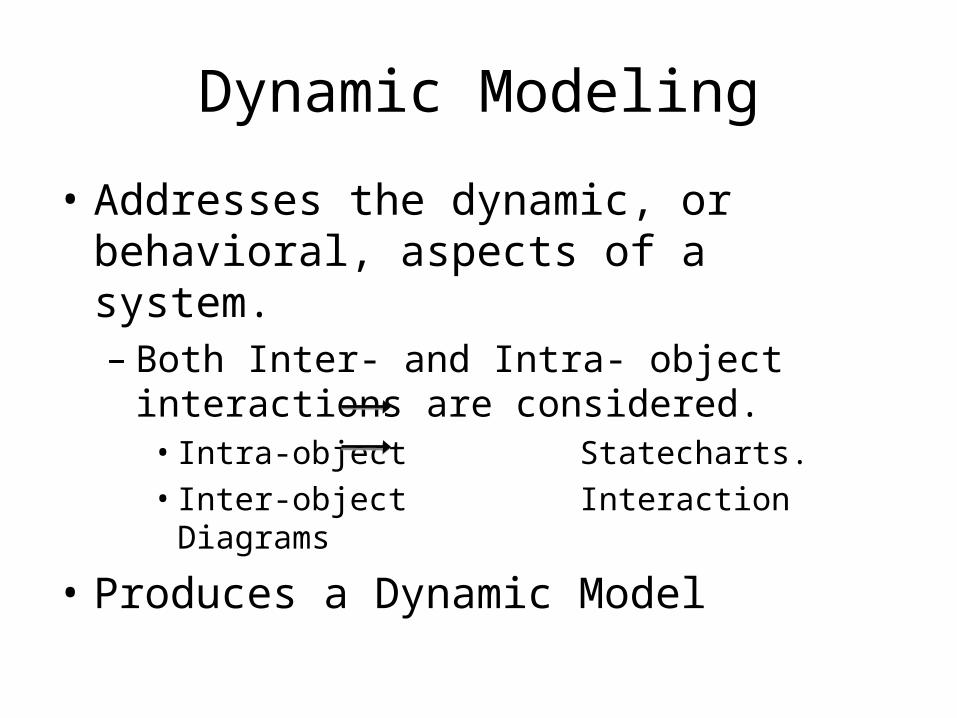
• Addresses the dynamic, or behavioral, aspects of a system.– Both Inter- and Intra- object interactions are
considered.• Intra-object Statecharts.• Inter-object Interaction Diagrams
• Produces a Dynamic Model

Dynamic Model
• Includes:– Interaction Diagrams• Collaboration Diagrams• Sequence Diagrams
– Message Sequence Description– Statechart Diagrams (if needed)

Overview of Dynamic Modeling
• Review of Interaction Modeling– What the different types of interaction diagrams
look like– How to choose which to use.
• How to perform Dynamic Analysis in COMET– Determining which objects to include in the
dynamic model.– Comparison of state vs. non-state oriented
dynamic analysis.
Object Interaction Modeling
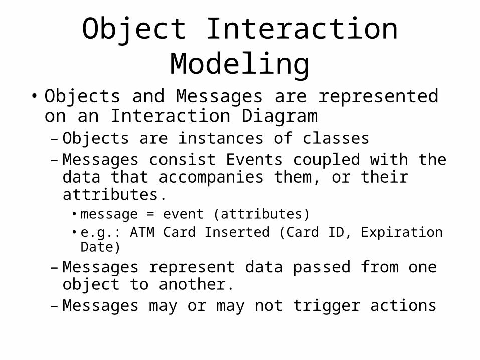
• Objects and Messages are represented on an Interaction Diagram– Objects are instances of classes– Messages consist Events coupled with the data
that accompanies them, or their attributes.• message = event (attributes)• e.g.: ATM Card Inserted (Card ID, Expiration Date)
– Messages represent data passed from one object to another.
– Messages may or may not trigger actions

Collaboration Diagrams
• Collaboration diagrams depict messages going from one object to another.
• Messages should have sequence numbers to indicate order.

Sequence Diagrams• Sequence Diagrams capture
time sequence of interactions between objects.
• Because the diagram depicts the time sequence, message sequence numbers are not necessary, but my be included.
• Note that the lifelines are dashed – we do not determine object lifecycles in the analysis modeling phase.

Collaboration vs. Squence• Only one or the other is needed.• COMET prescribes a slight preference for
collaboration diagrams.– An important part of design modeling is synthesizing
the collaboration diagrams – hence collaboration diagrams must be created for all sequence diagrams anyways.
• During the analysis modeling, COMET emphasizes capturing the information passed from one object to another, rather than the action taken when a message arrives.

What Interaction Diagrams Show
• Scenarios of Use Cases– A Scenario is a particular path through a Use Case.– Alternative paths may be selected based on
conditions.
• Generic interaction diagrams show all scenarios.
• Instance interaction diagrams show a single scenario.

Message Labels
• Message labels take the following form:– sequence expression: message name (attributes)– Sequence Expressions may include:• Message Sequence Number• Recurrence
– Iteration– Condition
– Attributes are arguments, data, or parameters sent with the message
• e.g.: 2.6 [Valid]: Valid PIN

Message Sequence Numbering
• Message sequence numbers in COMET consist of:– [first optional letter sequence] [numeric sequence]
[second optional letter sequence]
• e.g.:– A1– 1a– Use1.3invalid

Message Labeling (example)

Message Sequence Description
• The message sequence description is a narrative describing the interactions on an interaction diagram.
• Typically used to provide additional information that is not easy or appropriate to represent on the interaction diagrams.

Dynamic Analysis
• Determines how analysis model objects interact with each other.
• Begins with a Use Case– The sequence of internal interactions started by
external inputs defined in a Use Case are “followed” through the system to eventual system output.
• Is Iterative. – First objects associated with a use case are identified. – Then their interactions are considered and re-
considered.

Non-State Dependent Dynamic Analysis
1. Determine interface object(s).
2. Determine internal objects.
3. Determine object collaboration.
4. Consider alternative sequences.

Non-State Dependent Dynamic Analysis (example)
Use Case Name: View Workstation StatusActor: Factory OperatorSummary: Factory operator views the status of one or more
workstationsPrecondition: Factory operator is logged in.Description: Factory operator requests view of the status of
one or more factory workstations. The request may be made on demand, or by subscription to receive notification of status changes.
Alternatives: Factory workstation is down. Warning message is displayed.
Postcondition: Workstation status has been displayed.

Non-State Dependent Dynamic Analysis (example, cont)

State-Dependant Dynamic Analysis
1. Determine Objects and Interactions.1. Determine the interface object(s).2. Determine the state-dependant control
object(s).3. Determine other internal objects.4. Determine object collaboration.
2. Execute the Statechart.3. Consider Alternative Sequences.

Executing the Statechart
1. For each state transition caused by a message, determine all the actions that result from the change in state and the objects that execute the identified actions and activities.
2. For each triggered or enabled object, determine the messages generated and their destinations.
3. Show the determined internal and external messages on both the statechart and the interaction diagram.

State-Dependant Dynamic Analysis (banking example)
• Determine the main sequence:

State-Dependant Dynamic Analysis (banking example, cont)
• Execute the statechart

State-Dependant Dynamic Analysis (banking example)
• Determine Alternative Sequences
State-Dependant Dynamic Analysis (banking example)
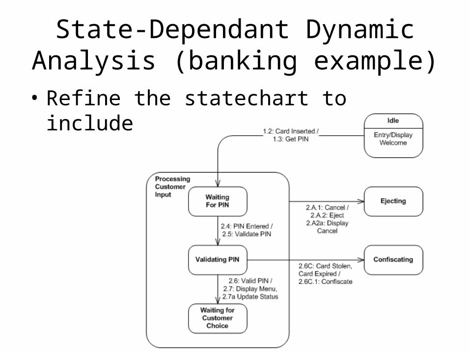
• Refine the statechart to include alternative sequences.

Summary
• Dynamic Analysis determines how objects interact to accomplish Use Cases.
• The Dynamic Model consists of:– Interaction Diagrams (Collaboration or Sequence)– Statechart Diagrams (if necessary)– Message Sequence Descriptions

Summary (cont)
• Dynamic Analysis can be state or non-state dependent.
• Dynamic Analysis consists of:– Determining external and internal objects.– Determining object collaborations.– Considering alternative sequences.