dynamic channel selections and performance analysis...
TRANSCRIPT

Dynamic Channel Selections and Performance
Analysis for High-Speed Train WiFi Network
Yawei Zhao, Yu Wu, Yaxiong Feng, Yuxin Zheng, Xuming Fang, Member, IEEE School of Information Science and Technology Southwest Jiaotong University, Chengdu, China
Abstract-The special communication scenario in High-Speed
Train (HST) not only leads to an increasing demand of high
throughput and continuous multimedia services but also arises
many other challenges for cellular network access technology,
such as high mobility, frequent and group handovers etc. In
order to address above problems, we propose an HST WiFi
network application scheme which adopts multi-hop technology
and introduces relay nodes to turn the wired backhaul into
wireless, in which, we propose a dynamic channel selection
scheme to avoid co-channel and adjacent channel interferences.
In addition, we also provide the comparison of single AP and
double APs deployment solutions to balance the bursting access
capability and the interference performance. In consideration of
the worst case of the HST WiFi system, we obtain the throughput
of the carriage-edge users, and observe that 80MHz channel
bandwidth can achieve the best throughput performance under
the deployment of single AP, while the throughput of 20MHz
channel bandwidth is the highest in the deployment of double
APs.
Key words-high-speed train, WiFi network, co-channel
interference, adjacent channel interference, channel selection, performance analysis
I. INTRODUCTION
The rapid increase of various mobile equipment and applications aggravates the demand of high throughput wireless communication system. Although the existing 4G network can meet the quality-of-service (QoS) more greatly than before, the QoS of cellular network will degrade significantly in mobile vehicle due to the specific propagation environment (e.g. high mobility, group and frequent handovers). In addition, high-speed rail is one of the main transportation ways of long journey, and passengers also need real-time and high volume multi-media services (e.g. audio and video). As a solution to these problems, WiFi network achieves more and more attention owing to cellular-to-WiFi offloading. High-Speed Train (HST) WiFi network, which is similar to indoor WiFi networks, can benefit from its high QoS, low cost and easy deployment. However, due to its high densely deployment, there is no guarantee to obtain high throughput because of the co-channel and adjacent channel interferences. Thus, it becomes a hot topic that how to deploy WiFi network appropriately to minimize its interference and maximize its throughput.
Recently, the Guangzhou to Kowloon Rail line, which is grouped by 4 carriages, has deployed a classical WiFi network based on 802.11n. In this train, each carriage has its own
This work was supported in part by 973 Program under Grant 2012CB316100, NSFC under Grant 61471303, and Program for Development of Science and Technology of China Railway Corporation under Grant Z20 l4-X002.
gateway node outside which communicates with the base station directly and its own AP inside which operates on the fixed non-adjacent 40MHz channel. The communication link between the gateway and its APs is connected by optical fiber. The proposed scheme can deploy on the new type train with few carriages and experience low adjacent frequency interference.
In fact, the domestic market share of the old type of high speed train is still dominant, which is freely grouped by 8 or 16 carriages. There is no cable communication connection between carriages, and this will lead following issues: (1) Adding cable communication connection will be difficult for the automatic carriages grouping; (2) With the increase of grouped carriages, it is costly to deploy gateways for each carriage; (3) The number of APs operated on different frequency bands will be 2-4 times than those before, which will further intensify the adj acent channel interference; (4) In order to improve economic efficiency and reduce the number of gateways, we may introduce wireless backhaul between carriages; (5) The standard physical layer and MAC layer technologies of 802.11n may not be able to meet the service demand of passengers in the high densely deployed WiFi network. According to the analysis above, we propose a new WiFi network deployment and channel selection scheme for the existing type of high speed train.
The paper is organized as follows. In Section II, we present the deployment of HST WiFi networks, including both of the classical and the proposed HST WiFi networks. Section III describes in detail the experienced interference. In Section IV, we give the channel allocation algorithm. Simulation analysis results are shown in Section V. Finally, we conclude our paper in Section VI.
II. DEPLOYMENT OF HST WIFI NETWORK
A. Classical HST WiFi network
As shown in Fig.1, the classical HST WiFi network deploys gateway nodes for each carriage or deploys limited number of gateway nodes in the head or middle of the train, and the backhaul between the carriages is by cable. This deployment is not complicated but has following disadvantages: (1) It is costly to deploy gateways for each carriage as the number of carriages increases; (2) If we reduce the number of gateways and only deploy it in the head or middle of the train, we must add wired backhaul between the carriages which will be difficult for automatic grouping of train; (3) For the deployment of multi-hop network, according to the above
978-1-4673-7629-7115$31.00 ©2015 IEEE
31
method, the information forwarded only by APs will cause bandwidth loss. In addition, the received signal strength from the carriage AP far from the gateway will be weak, which results in the low signal to noise ratio (SNR) and high bit error rate (BER). In brief, this HST WiFi network is not quite fit for the existing type of trains.
Fig.l Classical train WiFi network
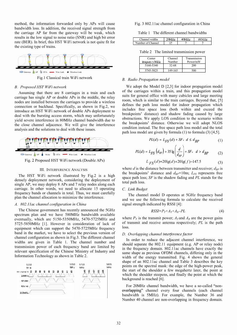
B. Proposed HST WiFi network
Assuming that there are 8 carriages in a train and each carriage has single AP or double APs in the middle, the relay nodes are installed between the carriages to provide a wireless connection or backhaul. Specifically, as shown in Fig.2, we introduce an HST WiFi network of double APs deployment to deal with the bursting access storm, which may unfortunately yield severe interference in 80MHz channel bandwidth due to the close channel adjacence. We will give the interference analysis and the solutions to deal with these issues.
Fig. 2 Proposed HST WiFi network (Double APs)
III. INTERFERENCE ANALYSIS
The HST WiFi network illustrated by Fig.2 is a high densely deployment network, considering the deployment of single AP, we may deploy 8 APs and 7 relay nodes along each carriage. In other words, we need to allocate 15 operating frequency bands or channels in total. Thus, we must carefully plan the channel allocation to minimize the interference.
A. 802. 11 ac channel configuration in China
The Chinese government has recently announced the 50Hz spectrum plan and we have 580MHz bandwidth available eventually, which are 5150-5350MHz, 5470-5725MHz and 5725-5850MHz [1]. However in consideration of lack of equipment which can support the 5470-5725MHz frequency band in the market, we have to select the previous version of channel configuration as shown in Fig.3. The different channel widths are given in Table 1. The channel number and transmission power of each frequency band are limited by relevant specification of the Chinese Ministry of Industry and Information Technology as shown in Table 2.
5150 5350 5710
MHz
5835 MHz
32
Fig. 3 802.11 ac channel configuration in China
Table 1 The different channel bandwidths
Channel widths NlUnber of Channel
Table 2 The limited transmission power
Center Channel Transmission frequency/MHz NlUllber Power/mW
5160-5340 32-68 200
5745-5825 149-165 500
B. Radio Propagation model
We adopt the Model D [2,3] for indoor propagation model of the carriages within a train, and this propagation model suits for general office with many cubicles and large meeting room, which is similar to the train carriages. Beyond that, [5] defines the path loss model for indoor propagation which includes free space loss (both within and exceed the breakpoints' distance) and shadow fading caused by large obstructions. We apply LOS condition to the scenario within the breakpoints' distance. Otherwise we will adopt NLOS condition instead. The free space path loss model and the total path loss model are given by formula (1) to formula (3) [4,5].
PLed) = LFS(d) + SF, d:<> dBP
PLed) = LFS (dBP ) + 35lg [�l + SF, d> d BP dBP
L FS(d)=20lg(d)+20lg(f)-147.5
(1)
(2)
(3)
where d is the distance between transmitter and receiver; dBP is the breakpoints' distance and dBP=lOm; LFS represents free space path loss; SF is the shadow fading and PL stands for the total path loss.
C. Link Budget
The channel model D operates at 50Hz frequency band and we use the following formula to calculate the received signal strength indicated by RSSI [4]:
RSSI=PT+AT+AR-PL (4)
where PT is the transmit power; ATand AR are the power gains of transmit and receive antenna respectively; PL is the path loss.
D. Overlapping channel interferencefactor
In order to reduce the adjacent channel interference, we should separate the 802.11 equipment (e.g. AP or relay node) in the frequency domain. 802.11 ac channels have exactly the same shape as previous OFDM channels, differing only in the width of the energy transmitted. Fig. 4 shows the general shape of an 802.11 ac channel and Table 3 describes the key points on the spectral mask: the edge of the high-power peak, the start of the shoulder a few megahertz later, the point at which the shoulder steepens, and finally the point at which the background is reached [6].
For 20MHz channel bandwidth, we have a so-called "nonoverlapping" channel every four channels (each channel bandwidth is 5MHz). For example, the Number 36 and Number 40 channel are non-overlapping in frequency domain.

Allocating non-overlapping channels for APs can restrain the adjacent channel interference, however it may reduce the available channels and only suit for less required channel situation.
-30
Spectrum
, I II
-20 - 11 -9 I ft
II 9 11
Typical Signal Spectrum
(an example)
30 f(MHz) Fig. 4 Spectral mask
Table 3 Spectral mask shape Channel width OdBr -20dBr -28dBr 40dBr
20MHz 9MHz 1 1 MHz 20MHz 30MHz 40MHz 19 21 40 60 80MHz 39 41 80 120
160MHz 79 81 160 240
The spectral filter characteristics in the 802.11 ac standard shown in Fig.S could be described by the following formula (20MHz for example)[7].
mU) =
-40, 6 -f-4, S 8 92 -f--, 9 9 lOf+90, ° -lOf+90,
8 92 --f--, 9 9 6 --f-4, S
-40,
f E( -00,-30]
fE[-30,-20]
fE[-20,-1l] fE[-1l,-9] fE[-9,9] (S) fE[9,1l]
fE[1l,20]
fE[20,30]
fE[30,(0)
Based on the formula, we can calculate the interference power distribution between the so-called "non-overlapping" channels, and we have the correlation between these channels. The level of correlation is defined as channel overlapping interference coefficient (COIC). The correlation level between non-overlapping channels is described in Fig. S.
-25 -
·35
.-12 .:H� olIU 48
Fig. S The correlation between non-overlapping channels
The COIC, the ratio of the common part between different spectral filters, is calculated by the correlation of
33
area under the mask curve. The calculated values of COIC are presented in Table 4, and the channel interval stands for the quantity of channels between two transmitting channels. For two APs transmit at the same channel, the COIC is 100% or 1, which means that the only differentiation between the desired signal and interference signal is the received signal power (co-channel interference).
Table 4 COIC of different channel intervals and different bandwidths
Channel width Channel interval COlC
0 1
4 0.37 20MHz
8 0.11
12 0
0 1
4 0.36 40MHz
8 0.096
12 0
0 1
80MHz 4 0.44
8 0
E. Interference model
To calculate the interference power with the given channel, we use the following formula:
K I . = I RSSIkmeCOIC-. mz k=l lj (6)
where 1m! represents the total interference power in the given node m on channel i, and RSShn is the interference power from node k on channel j. C01Cij is the channel overlapping interference coefficient between channels i and j.
IV. CHANNEL ALLOCATION ALGORITHM
We propose the channel allocation algorithm according to interference model shown in Fig. 6. The channel allocation algorithm is as follows:
(1) Serial numbers will be assigned to APs according to the location of the AP, for example, from the front to the rear of the train, and we add these APs to set A. Then we initialize the same operating channel for each AP and calculate the interference of each AP as the interference weight W of it.
(2) We will sort the APs which are in set A according to the interference weight W. The larger the interference, the higher the priority. For the APs whose interference is the same, we will choose the AP with smallest serial number as the highest priority.
(3) Calculate the interference weight W of AP with the highest priority under each available channel. Then, allocate the channel with the smallest W to this AP and remove this AP to set Q. After that, go to step (4) if there is no AP in set A, otherwise, switch to step (2).
(4) If the interference weight W of each AP in the system tends to be stable, the algorithm ends. Otherwise, we will clear the set Q and add all APs to the set A, then, switch to step (2).
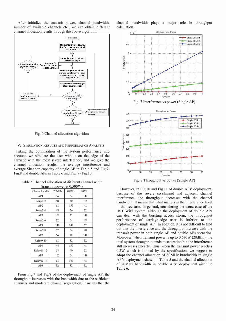
After initialize the transmit power, channel bandwidth, number of available channels etc., we can obtain different channel allocation results through the above algorithm.
Initialization
�----"------< Is the number ofAP
. setA zero?
Update the interference
weight of the network
topology
Fig. 6 Channel allocation algorithm
v. SIMULATION RESULTS AND PERFORMANCE ANALYSIS
Taking the optimization of the system performance into account, we simulate the user who is on the edge of the carriage with the most severe interference, and we give the channel allocation results, the average interference and average Shannon capacity of single AP in Table S and Fig.7-Fig.8 and double APs in Table 6 and Fig. 9- Fig. 10.
Table S Channel allocation of different channel width (transmit power is 0 SOOW)
Channel width 20MHz 40MHz 80MHz
API 36 64 149
Relay 1-2 48 40 32
AP2 68 157 48
Relay3-4 48 56 32
AP3 161 32 149
Relay5-6 32 64 48
AP4 149 149 32
Relay7-8 32 64 48
AP5 56 48 149
Relay9-10 68 32 32
AP6 44 157 48
Relayll-12 68 40 32
AP7 165 64 149
Relayl3-14 68 149 48
AP8 32 32 32
From Fig.7 and Fig.8 of the deployment of single AP, the throughput increases with the bandwidth due to the sufficient channels and moderate channel segregation. It means that the
34
channel bandwidth plays a major role calculation.
m throughput
Interference'v's Power
0.1 0.2 0.3 0.4 0.5 0.6 0.7 0.8 0.9 Power/w
Fig. 7 Interference vs power (Single AP)
Throughput V5 Power zror--�--,---r---,--'---r---,
200
180
6°1 ':-6 ---:'18:----:'::----::':---::':------::":----:':-----:'30 Power/w
Fig. 8 Throughput vs power (Single AP)
However, in Fig. 10 and Fig.ll of double APs' deployment, because of the severe co-channel and adjacent channel interference, the throughput decreases with the channel bandwidth. It means that what matters is the interference level in this scenario. In general, considering the worst case of the HST WiFi system, although the deployment of double APs can deal with the bursting access storm, the throughput performance of carriage-edge user is inferior to the deployment of single AP. In addition, it is not difficult to find out that the interference and the throughput increase with the transmit power in both single AP and double APs scenarios. Moreover, when transmit power is up to O.630W (28dBm), the total system throughput tends to saturation but the interference still increases linearly. Thus, when the transmit power reaches O.SW which is limited by the specification, we suggest to adopt the channel allocation of 80MHz bandwidth in single AP's deployment shown in Table S and the channel allocation of 20MHz bandwidth in double APs' deployment given in Table 6.
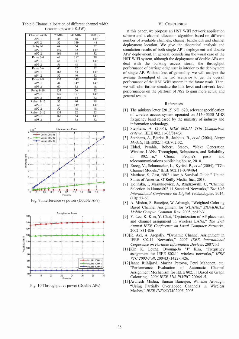
Table 6 Channel allocation of different channel width (transmit power is 0.5W)
Channel width 20MHz 40 MHz 80MHz API-I 44 48 149 API-2 32 149 48
Relayl-2 64 64 32 AP2-1 149 32 149 AP2-2 161 64 32
Relay 3-4 64 157 48 AP3-1 68 157 149 AP3-2 56 48 48
Relay 5-6 40 32 32 AP4-1 165 64 149 AP4-2 32 40 32
Relay 7-8 153 149 48 AP5-1 44 149 149 AP5-2 60 32 48
Relay 9-10 153 56 32 AP6-1 149 157 149 AP6-2 161 64 32
Relay 11-12 32 40 48 AP7-1 68 149 149 AP7-2 52 48 48
Relay 12-13 153 32 32 AP8-1 165 64 149 AP8-2 36 32 32
Interference vs Powar
Powerlw
Fig. 9 Interference vs power (Double APs)
Throughput \IS Power 100r---�---''---�---'----'---�----'
oo�--�--��--�--�----�--�--� 16 18 20 22 24 26 28 30
Powerlw
Fig. 10 Throughput vs power (Double APs)
35
VI. CONCLUSION
n this paper, we propose an HST WiFi network application scheme and a channel allocation algorithm based on different number of available channels, channel bandwidth and channel deployment location. We give the theoretical analysis and simulation results of both single AP's deployment and double APs' deployment. In general, considering the worst case of the HST WiFi system, although the deployment of double APs can deal with the bursting access storm, the throughput performance of carriage-edge user is inferior to the deployment of single AP. Without loss of generality, we will analyze the average throughput of the two scenarios to get the overall performance of the HST WiFi system in the future work. Then, we will also further simulate the link level and network level performances on the platform of NS2 to gain more actual and general results.
References
[1] The ministry letter [2012] NO. 620, relevant specification of wireless access system operated on 5150-5350 MHZ frequency band released by the ministry of industry and information technology.
[2] Stephens, A. (2004), IEEE 802. 11 TGn Comparison criteria, IEEE 802.11-03/814r31
[3] Stephens, A., Bjerke, B., Jechoux, B., et al. (2004). Usage Models, IEEE802.11-03/802r32.
[4] Eldad, Perahia, Robert, Stacey, "Next Generation Wireless LANs: Throughput, Robustness, and Reliability in 802.11n, " China: People's posts and telecommunications publishing house, 2010.
[5] Erceg, V., Schumacher, L., Kyritsi, P., et al. (2004), "TGn Channel Models, " IEEE 802.11-03/940r4
[6] Matthew, S, Gast, "802.11ac: A Survival Guide, " United States of America: O'Reilly Media, Inc., 2013.
[7] Dolinska, I, Masiukiewicz, A, Rzl:!dkowski, G, "Channel Selection in Home 802.11 Standard Networks, " The 10th International Conference on Digital Technologies, 2014, (10): 57-63
[8] A. Mishra, S. Baneijee, W Arbaugh, "Weighted Coloring Based Channel Assignment for WLANs, " SIGMOBILE Mobile Comput. Commun. Rev. 2005, pp19-31
[9] Y. Lee, K. Kim, Y. Choi, "Optimization of AP placement and channel assignment in wireless LANs, " The 27th Annual IEEE Conference on Local Computer Networks, 2002: 831-836
[10]R. Akl, A. Arepally, "Dynamic Channel Assignment in IEEE 802.11 Networks, " 2007 1EEE International Conference on Portable 1n/ormation Devices, 2007:1-5
[l1]Kin K. Leung, Byoung-Jo "J" Kim, "Frequency assignment for IEEE 802.11 wireless networks, " IEEE VTC 2003-Fall, 2004(3):1422-1426.
[12] Janne Riihijarvi, Marina Petrova, Petri Mahonen, etc. "Performance Evaluation of Automatic Channel Assignment Mechanism for IEEE 802.11 Based on Graph Colouring, " 2006 IEEE 17th PIMRC, 2006:1-5.
[13]Arunesh Mishra, Suman Banerjee, William Arbaugh, "Using Partially Overlapped Channels m Wireless Meshes, " IEEE INFOCOM 2005, 2005.