dynamic breakout ports - cisco.com · f)...
TRANSCRIPT
Dynamic Breakout Ports
This chapter contains the following sections:
• Configuration of Dynamic Breakout Ports, on page 1• Configuring Dynamic Breakout Ports Using the APIC GUI, on page 2• Configuring Dynamic Breakout Ports Using the NX-OS Style CLI, on page 4• Configuring Dynamic Breakout Ports Using the REST API, on page 8
Configuration of Dynamic Breakout PortsBreakout cables are suitable for very short links and offer a cost effective way to connect within racks andacross adjacent racks.
Breakout enables a 40 Gigabit (Gb) port to be split into four independent and logical 10Gb ports or a 100Gbport to be split into four independent and logical 25Gb ports.
Before you configure breakout ports, connect a 40Gb port to four 10Gb ports or a 100Gb port to four 25Gbports with one of the following cables:
• Cisco QSFP-4SFP10G
• Cisco QSFP-4SFP25G
The 40Gb to 10Gb dynamic breakout feature is supported on the access facing ports of the following switches:
• N9K-C9332PQ
• N9K-C93180LC-EX
• N9K-C9336C-FX
The 100Gb to 25Gb breakout feature is supported on the access facing ports of the following switches:
• N9K-C93180LC-EX
• N9K-C9336C-FX2
• N9K-C93180YC-FX
Observe the following guidelines and restrictions:
Dynamic Breakout Ports1
• In general, breakouts and port profiles (ports changed from uplink to downlink) are not supported on thesame port.
However, from Cisco APIC, Release 3.2, dynamic breakouts (both 100Gb and 40Gb) are supported onprofiled QSFP ports on the N9K-C93180YC-FX switch.
• Fast Link Failover policies are not supported on the same port with the dynamic breakout feature.
• Breakout subports can be used in the same way other port types in the policy model are used.
• When a port is enabled for dynamic breakout, other policies (expect monitoring policies) on the parentport are no longer valid.
• When a port is enabled for dynamic breakout, other EPG deployments on the parent port are no longervalid.
• A breakout sub-port can not be further broken out using a breakout policy group.
Configuring Dynamic Breakout Ports Using the APIC GUIConfigure a Breakout Leaf Port with an Leaf Interface Profile, associate the profile with a switch, and configurethe sub ports with the following steps.
You can also configure ports for breakout in the APIC GUI by navigating to Fabric > Inventory, and clickingTopology or Pod, or expanding Pod and clicking Leaf. Then, enable configuration and click the Interfacetab.
Note
Procedure
Before you begin
• The ACI fabric is installed, APIC controllers are online, and the APIC cluster is formed and healthy.
• An APIC fabric administrator account is available that will enable creating the necessary fabricinfrastructure configurations.
• The target leaf switches are registered in the ACI fabric and available.
• The 40GE or 100GE leaf switch ports are connected with Cisco breakout cables to the downlink ports.
Procedure
Step 1 On the menu bar, choose Fabric > External Access Policies.Step 2 In the Navigation pane, expand Interfaces and Leaf Interfaces and Profiles.Step 3 Right-click Profiles and choose Create Leaf Interface Profile.Step 4 Type the name and optional description, click the + symbol on Interface SelectorsStep 5 Perform the following:
a) Type a name (and optional description) for the Access Port Selector.
Dynamic Breakout Ports2
Dynamic Breakout PortsConfiguring Dynamic Breakout Ports Using the APIC GUI
b) In the Interface IDs field, type the slot and port for the breakout port.c) In the Interface Policy Group field, click the down arrow and choose Create Leaf Breakout Port
Group.d) Type the name (and optional description) for the Leaf Breakout Port Group.e) In the Breakout Map field, choose 10g-4x or 25g-4x.
For switches supporting breakout, see Configuration of Dynamic Breakout Ports, on page 1.
f) Click Submit.
Step 6 To assign a Breakout Port to an EPG, perform the following steps:
On the menu bar, choose Tenant > Application Profiles > Application EPG. Right-click on ApplicationEPG to open Create Application EPGdialog box, and perform the following steps:
a) Select the Statically Link with Leaves/Paths check box to gain access to the Leaves/Paths tab in thedialog box.
b) Complete one of the following sets of steps:
DescriptionOption
ThenIf you want to deploythe EPG on...
A node 1. Expand the Leaves area.
2. From the Node drop-down list, choose a node.
3. In the Encap field, enter the appropriate VLAN.
4. (Optional) From theDeployment Immediacy drop-down list, accept the defaultOn Demand or choose Immediate.
5. (Optional) From the Mode drop-down list, accept the default Trunk or chooseanother mode.
A port on the node 1. Expand the Paths area.
2. From the Path drop-down list, choose the appropriate node and port.
3. (Optional) In the Deployment Immediacy field drop-down list, accept thedefault On Demand or choose Immediate.
4. (Optional) From the Mode drop-down list, accept the default Trunk or chooseanother mode.
5. In the Port Encap field, enter the secondary VLAN to be deployed.
6. (Optional) In the Primary Encap field, enter the primary VLAN to be deployed.
Step 7 To associate the Leaf Interface Profile to a the leaf switch, perform the following steps:a) Expand Switches and Leaf Switches, and Profiles.b) Right-click Profiles and select Create Leaf Profiles.c) Type the name and optional description of the Leaf Profile.d) Click the + symbol on the Leaf Selectors area.e) Type the leaf selector name and an optional description.
Dynamic Breakout Ports3
Dynamic Breakout PortsConfiguring Dynamic Breakout Ports Using the APIC GUI
f) Click the down arrow on the Blocks field and choose the switch to be associated with the breakout leafinterface profile.
g) Click the down arrow on the Policy Group field and choose Create Access Switch Policy Group.h) Type a name and optional description for the Access Switch Policy Group.i) Optional. Enable other policies.j) Click Submit.k) Click Update.l) Click Next.m) In theAssociations Interface Selector Profiles area, choose the Interface Selector Profile you previously
created for the breakout port.n) Click Finish.
Step 8 To verify the breakout port has been split into four sub ports, perform the following steps:a) On the Menu bar, click Fabric > Inventory.b) On the Navigation bar, click the Pod and Leaf where the breakout port is located.c) Expand Interfaces and Physical Interfaces.
You should see four ports at the position where the breakout port was configured. For example, if youconfigured 1/10 as a breakout port, you should see the following:
• eth1/10/1
• eth1/10/2
• eth1/10/3
• eth1/10/4
Step 9 To configure the sub ports, perform the following steps:a) On the Menu bar, click Fabric > External Access Policies.b) On the Navigation bar, expand Interfaces, Leaf Interfaces, Profiles, and the breakout leaf interface
profile you previously created.c) Click the Breakout Port Access Port Selector profile you previously created.d) On the Sub Port Blocks area, click the + symbol.e) In the Interface IDs field, enter the IDs for the four sub ports in a format such as 1/10/1-4.f) Click Submit.
Configuring Dynamic Breakout Ports Using the NX-OS Style CLIUse the following steps to configure a breakout port, verify the configuration, and configure an EPG on a subport, using the NX-OS style CLI.
Before you begin
• The ACI fabric is installed, APIC controllers are online, and the APIC cluster is formed and healthy.
• An APIC fabric administrator account is available that will enable creating the necessary fabricinfrastructure configurations.
Dynamic Breakout Ports4
Dynamic Breakout PortsConfiguring Dynamic Breakout Ports Using the NX-OS Style CLI
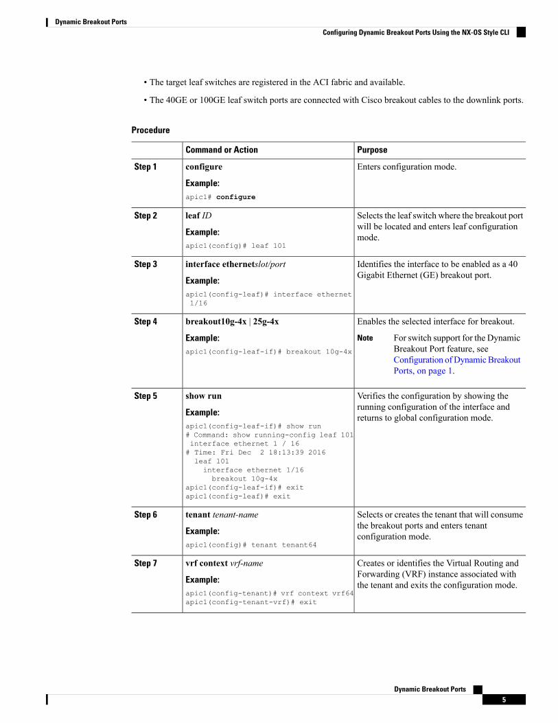
• The target leaf switches are registered in the ACI fabric and available.
• The 40GE or 100GE leaf switch ports are connected with Cisco breakout cables to the downlink ports.
Procedure
PurposeCommand or Action
Enters configuration mode.configure
Example:
Step 1
apic1# configure
Selects the leaf switch where the breakout portwill be located and enters leaf configurationmode.
leaf ID
Example:apic1(config)# leaf 101
Step 2
Identifies the interface to be enabled as a 40Gigabit Ethernet (GE) breakout port.
interface ethernetslot/port
Example:
Step 3
apic1(config-leaf)# interface ethernet1/16
Enables the selected interface for breakout.breakout10g-4x | 25g-4xStep 4
Example: For switch support for the DynamicBreakout Port feature, seeConfiguration ofDynamicBreakoutPorts, on page 1.
Note
apic1(config-leaf-if)# breakout 10g-4x
Verifies the configuration by showing therunning configuration of the interface andreturns to global configuration mode.
show run
Example:apic1(config-leaf-if)# show run# Command: show running-config leaf 101
Step 5
interface ethernet 1 / 16# Time: Fri Dec 2 18:13:39 2016leaf 101interface ethernet 1/16breakout 10g-4x
apic1(config-leaf-if)# exitapic1(config-leaf)# exit
Selects or creates the tenant that will consumethe breakout ports and enters tenantconfiguration mode.
tenant tenant-name
Example:apic1(config)# tenant tenant64
Step 6
Creates or identifies the Virtual Routing andForwarding (VRF) instance associated withthe tenant and exits the configuration mode.
vrf context vrf-name
Example:apic1(config-tenant)# vrf context vrf64apic1(config-tenant-vrf)# exit
Step 7
Dynamic Breakout Ports5
Dynamic Breakout PortsConfiguring Dynamic Breakout Ports Using the NX-OS Style CLI
PurposeCommand or Action
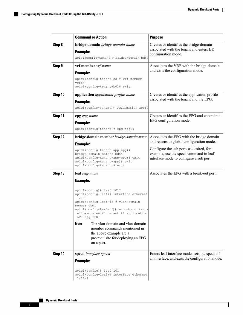
Creates or identifies the bridge-domainassociated with the tenant and enters BDconfiguration mode.
bridge-domain bridge-domain-name
Example:apic1(config-tenant)# bridge-domain bd64
Step 8
Associates the VRF with the bridge-domainand exits the configuration mode.
vrf member vrf-name
Example:
Step 9
apic1(config-tenant-bd)# vrf membervrf64apic1(config-tenant-bd)# exit
Creates or identifies the application profileassociated with the tenant and the EPG.
application application-profile-name
Example:
Step 10
apic1(config-tenant)# application app64
Creates or identifies the EPG and enters intoEPG configuration mode.
epg epg-name
Example:
Step 11
apic1(config-tenant)# epg epg64
Associates the EPG with the bridge domainand returns to global configuration mode.
bridge-domainmember bridge-domain-name
Example:
Step 12
Configure the sub ports as desired, forexample, use the speed command in leafinterface mode to configure a sub port.
apic1(config-tenant-app-epg)#bridge-domain member bd64apic1(config-tenant-app-epg)# exitapic1(config-tenant-app)# exitapic1(config-tenant)# exit
Associates the EPG with a break-out port.leaf leaf-name
Example:
Step 13
apic1(config)# leaf 1017apic1(config-leaf)# interface ethernet1/13apic1(config-leaf-if)# vlan-domainmember dom1apic1(config-leaf-if)# switchport trunkallowed vlan 20 tenant t1 applicationAP1 epg EPG1
The vlan-domain and vlan-domainmember commands mentioned inthe above example are apre-requisite for deploying an EPGon a port.
Note
Enters leaf interface mode, sets the speed ofan interface, and exits the configuration mode.
speed interface-speed
Example:
Step 14
apic1(config)# leaf 101apic1(config-leaf)# interface ethernet1/16/1
Dynamic Breakout Ports6
Dynamic Breakout PortsConfiguring Dynamic Breakout Ports Using the NX-OS Style CLI
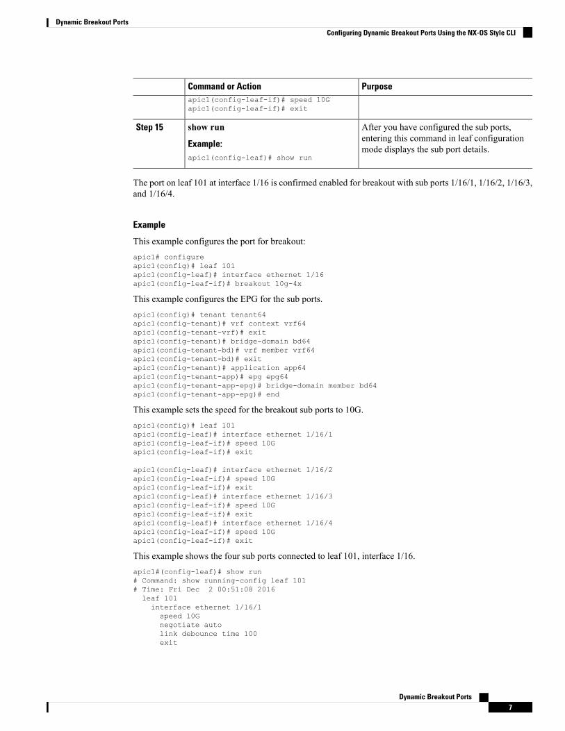
PurposeCommand or Actionapic1(config-leaf-if)# speed 10Gapic1(config-leaf-if)# exit
After you have configured the sub ports,entering this command in leaf configurationmode displays the sub port details.
show run
Example:apic1(config-leaf)# show run
Step 15
The port on leaf 101 at interface 1/16 is confirmed enabled for breakout with sub ports 1/16/1, 1/16/2, 1/16/3,and 1/16/4.
Example
This example configures the port for breakout:apic1# configureapic1(config)# leaf 101apic1(config-leaf)# interface ethernet 1/16apic1(config-leaf-if)# breakout 10g-4x
This example configures the EPG for the sub ports.apic1(config)# tenant tenant64apic1(config-tenant)# vrf context vrf64apic1(config-tenant-vrf)# exitapic1(config-tenant)# bridge-domain bd64apic1(config-tenant-bd)# vrf member vrf64apic1(config-tenant-bd)# exitapic1(config-tenant)# application app64apic1(config-tenant-app)# epg epg64apic1(config-tenant-app-epg)# bridge-domain member bd64apic1(config-tenant-app-epg)# end
This example sets the speed for the breakout sub ports to 10G.apic1(config)# leaf 101apic1(config-leaf)# interface ethernet 1/16/1apic1(config-leaf-if)# speed 10Gapic1(config-leaf-if)# exit
apic1(config-leaf)# interface ethernet 1/16/2apic1(config-leaf-if)# speed 10Gapic1(config-leaf-if)# exitapic1(config-leaf)# interface ethernet 1/16/3apic1(config-leaf-if)# speed 10Gapic1(config-leaf-if)# exitapic1(config-leaf)# interface ethernet 1/16/4apic1(config-leaf-if)# speed 10Gapic1(config-leaf-if)# exit
This example shows the four sub ports connected to leaf 101, interface 1/16.apic1#(config-leaf)# show run# Command: show running-config leaf 101# Time: Fri Dec 2 00:51:08 2016leaf 101interface ethernet 1/16/1speed 10Gnegotiate autolink debounce time 100exit
Dynamic Breakout Ports7
Dynamic Breakout PortsConfiguring Dynamic Breakout Ports Using the NX-OS Style CLI
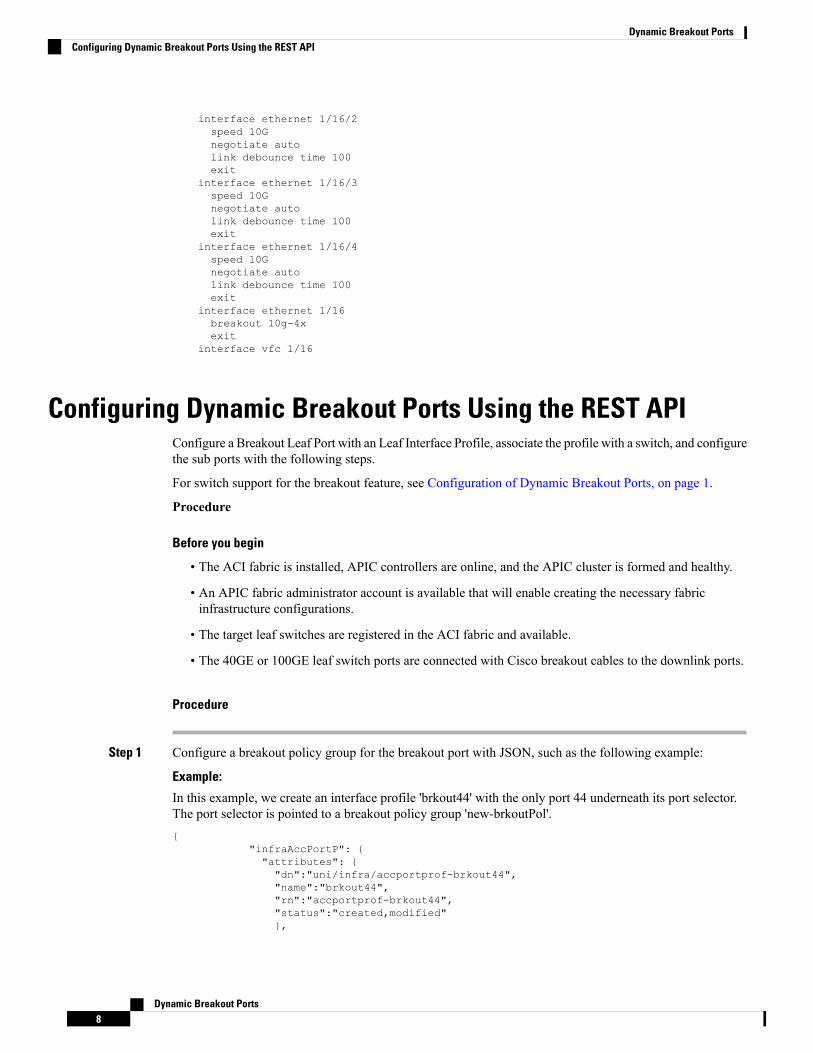
interface ethernet 1/16/2speed 10Gnegotiate autolink debounce time 100exit
interface ethernet 1/16/3speed 10Gnegotiate autolink debounce time 100exit
interface ethernet 1/16/4speed 10Gnegotiate autolink debounce time 100exit
interface ethernet 1/16breakout 10g-4xexit
interface vfc 1/16
Configuring Dynamic Breakout Ports Using the REST APIConfigure a Breakout Leaf Port with an Leaf Interface Profile, associate the profile with a switch, and configurethe sub ports with the following steps.
For switch support for the breakout feature, see Configuration of Dynamic Breakout Ports, on page 1.
Procedure
Before you begin
• The ACI fabric is installed, APIC controllers are online, and the APIC cluster is formed and healthy.
• An APIC fabric administrator account is available that will enable creating the necessary fabricinfrastructure configurations.
• The target leaf switches are registered in the ACI fabric and available.
• The 40GE or 100GE leaf switch ports are connected with Cisco breakout cables to the downlink ports.
Procedure
Step 1 Configure a breakout policy group for the breakout port with JSON, such as the following example:
Example:
In this example, we create an interface profile 'brkout44' with the only port 44 underneath its port selector.The port selector is pointed to a breakout policy group 'new-brkoutPol'.{
"infraAccPortP": {"attributes": {"dn":"uni/infra/accportprof-brkout44","name":"brkout44","rn":"accportprof-brkout44","status":"created,modified"},
Dynamic Breakout Ports8
Dynamic Breakout PortsConfiguring Dynamic Breakout Ports Using the REST API
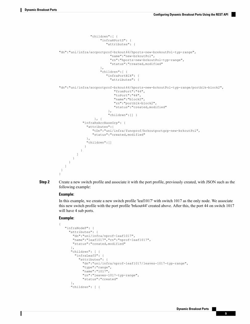
"children":[ {"infraHPortS": {
"attributes": {
"dn":"uni/infra/accportprof-brkout44/hports-new-brekoutPol-typ-range","name":"new-brkoutPol","rn":"hports-new-brkoutPol-typ-range","status":"created,modified"
},"children":[ {
"infraPortBlk": {"attributes": {
"dn":"uni/infra/accportprof-brkout44/hports-new-brkoutPol-typ-range/portblk-block2","fromPort":"44","toPort":"44","name":"block2","rn":"portblk-block2","status":"created,modified"
},"children":[] }
}, {"infraRsAccBaseGrp": {"attributes":{
"tDn":"uni/infra/funcprof/brkoutportgrp-new-brkoutPol","status":"created,modified"
},"children":[]}
}]
}}
]}}
Step 2 Create a new switch profile and associate it with the port profile, previously created, with JSON such as thefollowing example:
Example:
In this example, we create a new switch profile 'leaf1017' with switch 1017 as the only node. We associatethis new switch profile with the port profile 'brkout44' created above. After this, the port 44 on switch 1017will have 4 sub ports.
Example:{
"infraNodeP": {"attributes": {"dn":"uni/infra/nprof-leaf1017","name":"leaf1017","rn":"nprof-leaf1017","status":"created,modified"},"children": [ {"infraLeafS": {"attributes": {"dn":"uni/infra/nprof-leaf1017/leaves-1017-typ-range","type":"range","name":"1017","rn":"leaves-1017-typ-range","status":"created"
},"children": [ {
Dynamic Breakout Ports9
Dynamic Breakout PortsConfiguring Dynamic Breakout Ports Using the REST API
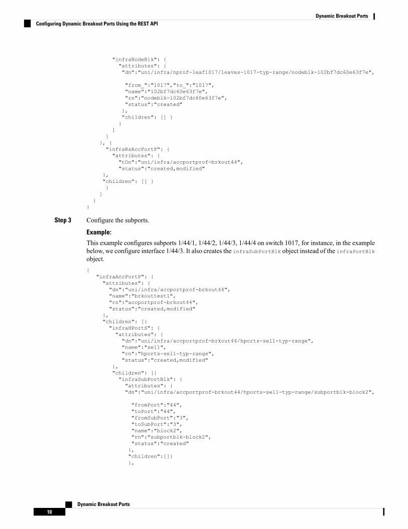
"infraNodeBlk": {"attributes": {"dn":"uni/infra/nprof-leaf1017/leaves-1017-typ-range/nodeblk-102bf7dc60e63f7e",
"from_":"1017","to_":"1017","name":"102bf7dc60e63f7e","rn":"nodeblk-102bf7dc60e63f7e","status":"created"},"children": [] }}
]}
}, {"infraRsAccPortP": {"attributes": {"tDn":"uni/infra/accportprof-brkout44","status":"created,modified"
},"children": [] }}
]}
}
Step 3 Configure the subports.
Example:
This example configures subports 1/44/1, 1/44/2, 1/44/3, 1/44/4 on switch 1017, for instance, in the examplebelow, we configure interface 1/44/3. It also creates the infraSubPortBlk object instead of the infraPortBlkobject.{
"infraAccPortP": {"attributes": {"dn":"uni/infra/accportprof-brkout44","name":"brkouttest1","rn":"accportprof-brkout44","status":"created,modified"
},"children": [{"infraHPortS": {"attributes": {"dn":"uni/infra/accportprof-brkout44/hports-sel1-typ-range","name":"sel1","rn":"hports-sel1-typ-range","status":"created,modified"
},"children": [{"infraSubPortBlk": {"attributes": {"dn":"uni/infra/accportprof-brkout44/hports-sel1-typ-range/subportblk-block2",
"fromPort":"44","toPort":"44","fromSubPort":"3","toSubPort":"3","name":"block2","rn":"subportblk-block2","status":"created"},"children":[]}},
Dynamic Breakout Ports10
Dynamic Breakout PortsConfiguring Dynamic Breakout Ports Using the REST API
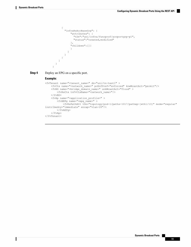
{"infraRsAccBaseGrp": {
"attributes": {"tDn":"uni/infra/funcprof/accportgrp-p1","status":"created,modified"
},"children":[]}}
]}
}]
}}
Step 4 Deploy an EPG on a specific port.
Example:<fvTenant name="<tenant_name>" dn="uni/tn-test1" >
<fvCtx name="<network_name>" pcEnfPref="enforced" knwMcastAct="permit"/><fvBD name="<bridge_domain_name>" unkMcastAct="flood" >
<fvRsCtx tnFvCtxName="<network_name>"/></fvBD><fvAp name="<application_profile>" >
<fvAEPg name="<epg_name>" ><fvRsPathAtt tDn="topology/pod-1/paths-1017/pathep-[eth1/13]" mode="regular"
instrImedcy="immediate" encap="vlan-20"/></fvAEPg>
</fvAp></fvTenant>
Dynamic Breakout Ports11
Dynamic Breakout PortsConfiguring Dynamic Breakout Ports Using the REST API

Dynamic Breakout Ports12
Dynamic Breakout PortsConfiguring Dynamic Breakout Ports Using the REST API