dx-net-devicenet field bus connection devicenet …pub/@electrical/... · 0.1 target group ... 3.5...
TRANSCRIPT

Manual 02/14 MN04012005Z-EN
PowerXL™
DX-NET-DEVICENET
Field bus connection DeviceNet
or Variable Frequency Drives DA1
All brand and product names are trademarks or registered trademarks of the owner concerned.
Emergency On Call ServicePlease call your local representative:http://www.eaton.eu/aftersalesorHotline of the After Sales Service:+49 (0) 180 5 223822 (de, en)[email protected]
For customers in US/Canada contact:
EatonCare Customer Support Center
Call the EatonCare Support Center if you need assistance with placing an order, stock availability or proof of shipment, expediting an existing order, emergency ship-ments, product price information, returns other than warranty returns, and informa-tion on local distributors or sales offices.
Voice: 877-ETN-CARE (386-2273) (8:00 a.m. – 6:00 p.m. EST)After-Hours Emergency: 800-543-7038 (6:00 p.m. – 8:00 a.m. EST)
Drives Technical Resource Center
Voice: 877-ETN-CARE (386-2273) option 2, option 6(8:00 a.m. – 5:00 p.m. Central Time U.S. [UTC-6])email: [email protected]/drives
Original Operating InstructionsThe German-language edition of this document is the original operating manual.
Translation of the original operating manualAll editions of this document other than those in German language are translations of the original German manual.
1st published 2014, edition date 02/14© 2014 by Eaton Industries GmbH, 53105 Bonn
Production: René WiegandTranslation: globaldocs GmbH
All rights reserved, including those of the translation.
No part of this manual may be reproduced in any form (printed, photocopy, microfilm or any other process) or processed, duplicated or distributed by means of electronic systems without written permission of Eaton Industries GmbH, Bonn.
Subject to alteration without notice.
Rück
en
bre
ite
fest
lege
n!
(1 B
latt
= 0
,10
6 m
m,
gilt
nur
für
XB
S)
(1 B
latt
= 0
,08
0 m
m f
ür
Ebe
rwe
in D
igit
ald
ruck b
ei 80
g/m
2)
I
Before commencing the installation
• Disconnect the power supply of the device.
• Ensure that devices cannot be accidentally restarted.
• Verify isolation from the supply.
• Earth and short circuit the device.
• Cover or enclose any adjacent live components.
• Follow the engineering instructions (AWA/IL) for the device concerned.
• Only suitably qualified personnel in accordance with EN 50110-1/-2 (VDE 0105 Part 100) may work on this device/system.
• Before installation and before touching the device ensure that you are free of electrostatic charge.
• The functional earth (FE, PES) must be connected to the protective earth (PE) or the potential equalisation. The system installer is responsible for implementing this connection.
• Connecting cables and signal lines should be installed so that inductive or capacitive interference does not impair the automation functions.
• Install automation devices and related operating elements in such a way that they are well protected against unintentional operation.
• Suitable safety hardware and software measures should be implemented for the I/O interface so that an open circuit on the signal side does not result in undefined states in the automation devices.
• Ensure a reliable electrical isolation of the extra-low voltage of the 24 V supply. Only use power supply units complying with IEC 60364-4-41 (VDE 0100 Part 410) or HD384.4.41 S2.
• Deviations of the mains voltage from the rated value must not exceed the tolerance limits given in the specifications, otherwise this may cause malfunction and dangerous operation.
• Emergency stop devices complying with IEC/EN 60204-1 must be effective in all operating modes of the automation devices. Unlatching the emergency-stop devices must not cause a restart.
• Devices that are designed for mounting in housings or control cabinets must only be operated and controlled after they have been installed and with the housing closed. Desktop or portable units must only be operated and controlled in enclosed housings.
• Measures should be taken to ensure the proper restart of programs interrupted after a voltage dip or failure. This should not cause dangerous operating states even for a short time. If necessary, emergency-stop devices should be implemented.
• Wherever faults in the automation system may cause injury or material damage, external measures must be implemented to ensure a safe operating state in the event of a fault or malfunction (for example, by means of separate limit switches, mechanical interlocks etc.).
• Depending on their degree of protection, frequency inverters may contain live bright metal parts, moving or rotating components or hot surfaces during and immediately after operation.
• Removal of the required covers, improper installation or incorrect operation of motor or frequency inverter may cause the failure of the device and may lead to serious injury or damage.
• The applicable national accident prevention and safety regulations apply to all work carried on live frequency inverters.
• The electrical installation must be carried out in accordance with the relevant regulations (e. g. with regard to cable cross sections, fuses, PE).
• Transport, installation, commissioning and maintenance work must be carried out only by qualified personnel (IEC 60364, HD 384 and national occupational safety regulations).
• Installations containing frequency inverters must be provided with additional monitoring and protective devices in accordance with the applicable safety regulations. Modifications to the frequency inverters using the operating software are permitted.
• All covers and doors must be kept closed during operation.
• To reduce the hazards for people or equipment, the user must include in the machine design measures that restrict the consequences of a malfunction or failure of the drive (increased motor speed or sudden standstill of motor). These measures include:
– Other independent devices for monitoring safety-related variables (speed, travel, end positions etc.).
– Electrical or non-electrical system-wide measures (electrical or mechanical interlocks).
– Never touch live parts or cable connections of the frequency inverter after it has been disconnected from the power supply. Due to the charge in the capacitors, these parts may still be live after disconnection. Fit appropriate warning signs.
Eato
n In
dust
ries
Gm
bHS
afet
y in
stru
ctio
nsDanger!
Dangerous electrical voltage!

II

Table of contents
0 About this manual ..................................................................... 3
0.1 Target group................................................................................. 3
0.2 Reading conventions.................................................................... 40.2.1 Hazard warnings of material damages ......................................... 40.2.2 Hazard warnings of personal injury .............................................. 40.2.3 Tips............................................................................................... 4
0.3 Abbreviations and Symbols.......................................................... 5
0.4 Units of measurement ................................................................. 6
0.5 Data Types ................................................................................... 6
1 Device series............................................................................... 7
1.1 Checking the Delivery .................................................................. 7
1.2 Key to part numbers..................................................................... 8
1.3 Designation at DX-NET-DEVICENET ............................................ 8
1.4 General rated operational data ..................................................... 9
1.5 Proper use.................................................................................... 10
1.6 Maintenance and inspection ........................................................ 11
1.7 Storage......................................................................................... 11
1.8 Service and warranty.................................................................... 11
1.9 Disposal........................................................................................ 11
2 Engineering................................................................................. 13
2.1 DeviceNet .................................................................................... 13
2.2 LED indicators .............................................................................. 142.2.1 LED MS........................................................................................ 142.2.2 LED NS......................................................................................... 14
3 Installation .................................................................................. 15
3.1 Introduction .................................................................................. 15
3.2 Notes on the documentation ....................................................... 16
3.3 Notes on the mechanical surface mounting ................................ 16
3.4 Mounting for frame sizes FS2 and FS3........................................ 17
3.5 Mounting from frame size FS4 .................................................... 19
3.6 Installing the fieldbus connection................................................. 213.6.1 Pin assignment............................................................................. 213.6.2 Bus termination resistor............................................................... 223.6.3 Max. cable lengths ....................................................................... 22
3.7 Install field bus ............................................................................. 23
DX-NET-DEVICENET 02/14 MN04012005ZDE www.eaton.com 1

4 Commissioning .......................................................................... 25
4.1 DA1 variable frequency drives ..................................................... 25
4.2 EDS file ........................................................................................ 25
4.3 Addressing................................................................................... 25
4.4 Engineering the module............................................................... 26
4.5 General information about the DeviceNet field bus system........ 284.5.1 Object model ............................................................................... 28
4.6 Supported objects........................................................................ 294.6.1 Identity Object (01hex).................................................................. 304.6.2 DeviceNet Object (03hex) ............................................................. 314.6.3 ADI Object (A2hex) ....................................................................... 324.6.4 Connection Object (05hex) ........................................................... 33
4.7 Operation ..................................................................................... 414.7.1 Cyclic data.................................................................................... 41
4.8 Parameter .................................................................................... 464.8.1 List of parameters........................................................................ 47
2 DX-NET-DEVICENET 02/14 MN04012005ZDE www.eaton.com
0 About this manual
0.1 Target group
0 About this manual
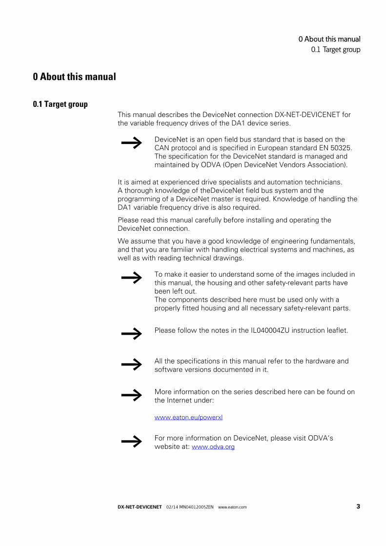
0.1 Target groupThis manual describes the DeviceNet connection DX-NET-DEVICENET for the variable frequency drives of the DA1 device series.
It is aimed at experienced drive specialists and automation technicians. A thorough knowledge of theDeviceNet field bus system and the programming of a DeviceNet master is required. Knowledge of handling the DA1 variable frequency drive is also required.
Please read this manual carefully before installing and operating the DeviceNet connection.
We assume that you have a good knowledge of engineering fundamentals, and that you are familiar with handling electrical systems and machines, as well as with reading technical drawings.
→ DeviceNet is an open field bus standard that is based on the CAN protocol and is specified in European standard EN 50325. The specification for the DeviceNet standard is managed and maintained by ODVA (Open DeviceNet Vendors Association).
→ To make it easier to understand some of the images included in this manual, the housing and other safety-relevant parts have been left out.The components described here must be used only with a properly fitted housing and all necessary safety-relevant parts.
→ Please follow the notes in the IL040004ZU instruction leaflet.
→ All the specifications in this manual refer to the hardware and software versions documented in it.
→ More information on the series described here can be found on the Internet under:
www.eaton.eu/powerxl
→ For more information on DeviceNet, please visit ODVA‘s website at: www.odva.org
DX-NET-DEVICENET 02/14 MN04012005ZEN www.eaton.com 3

0 About this manual
0.2 Reading conventions
0.2 Reading conventions
Symbols used in this manual have the following meanings:
▶ Indicates instructions to be followed.
0.2.1 Hazard warnings of material damages
0.2.2 Hazard warnings of personal injury
0.2.3 Tips
NOTICE
Warns about the possibility of material damage.
CAUTION
Warns of the possibility of hazardous situations that may possibly cause slight injury.
WARNING
Warns of the possibility of hazardous situations that could result in serious injury or even death.
DANGER
Warns of hazardous situations that result in serious injury or death.
→ Indicates useful tips.
4 DX-NET-DEVICENET 02/14 MN04012005ZEN www.eaton.com

0 About this manual
0.3 Abbreviations and Symbols
0.3 Abbreviations and Symbols
The following abbreviations are used in this manual:
ADI Application Data Instance
CIP Common Industrial Protocol
COS Change of State
CW Control Word
LED Light Emitting Diode (LED)
LSB Least Significant Bit
MAC ID Media Access Control Identifier
MSB Most Significant Bit
ODVA Open DeviceNet Vendor AssociationThe user organization (www.odva.org) for DeviceNet
PC Personal Computer
PDI Process Data Interface
PNU Parameter number
PD Process Data
PLC Programmable logic controller
SW Status Word
UL Underwriters Laboratories
xxhex Used to indicate hexadecimal numbers(x = 0, 1, …, 9, A, B, C, D, E, F)
DX-NET-DEVICENET 02/14 MN04012005ZEN www.eaton.com 5

0 About this manual
0.4 Units of measurement
0.4 Units of measurement
Every physical dimension included in this manual uses international metric system units, otherwise known as SI (Système International d’Unités) units. For the purpose of the equipment's UL certification, some of these dimensions are accompanied by their equivalents in imperial units.
Table 1: Unit conversion examples
0.5 Data TypesThis manual refers to the following data types for the DeviceNet field bus system:
Table 2: Data types in DeviceNet
designation US-American value
US-Americandesignation
SI value Conversion value
Length 1 in (’’) inch 25.4 mm 0.0394
Power 1 HP = 1.014 PS horsepower 0.7457 kW 1.341
Moment of torque
1 lbf in pound-force inches 0.113 Nm 8.851
Temperature 1 °F (TF) Fahrenheit -17.222 °C (TC) TF = TC × 9/5 + 32
Rotational speed
1 rpm Revolutions per minute 1 min-1 1
Weight 1 lb pound 0.4536 kg 2.205
Flow rate 1 cfm cubic feet per minute 1.698 m3/n 0.5889
Data type Data Length Range Name
[Bits] Min Max
BOOL 1 0 (FALSE) 1 (TRUE) Boolean
SINT 8 -128 127 Signed Short Integer
USINT 8 0 255 Unsigned Short Integer
INT 16 -32768 32767 Integer
UINT 16 0 65535 Unsigned Integer
DINT 32 -231 231 -1 Signed Double Integer
UDINT 32 0 232 -1 Unsigned Double Integer
6 DX-NET-DEVICENET 02/14 MN04012005ZEN www.eaton.com

1 Device series
1.1 Checking the Delivery
1 Device series
1.1 Checking the Delivery
Your fieldbus connection was carefully packaged and handed over for shipment. The devices should be shipped only in their original packaging with suitable transportation materials. Please observe the labels and instructions on the packaging and for handling the unpacked device.
▶ Open the packaging with adequate tools and inspect the contents immediately after receipt in order to ensure that they are complete and undamaged.
The packaging must contain the following parts:
• a DX-NET-DEVICENET fieldbus connection• the instruction leaflet IL040004ZU.
Figure 1: Equipment supplied with fieldbus connection DX-NET-DEVICENET
→ Before opening the package, please check the nameplate on it to make sure that you received the correct connection.
NS
MS
DeviceNet
DX-NET-DEVICENET 02/14 MN04012005ZEN www.eaton.com 7
1 Device series
1.2 Key to part numbers
1.2 Key to part numbers
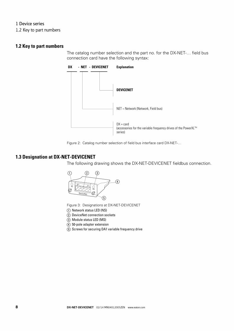
The catalog number selection and the part no. for the DX-NET-… field bus connection card have the following syntax:
Figure 2: Catalog number selection of field bus interface card DX-NET-…
1.3 Designation at DX-NET-DEVICENETThe following drawing shows the DX-NET-DEVICENET fieldbus connection.
Figure 3: Designations at DX-NET-DEVICENET
a Network status LED (NS)
b DeviceNet connection sockets
c Module status LED (MS)
d 50-pole adapter extension
e Screws for securing DA1 variable frequency drive
DX - NET - DEVICENET Explanation
DEVICENET
NET = Network (Network, Field bus)
DX = card(accessories for the variable frequency drives of the PowerXL™ series)
NS
MS
DeviceNet
②
⑤
① ③
④
8 DX-NET-DEVICENET 02/14 MN04012005ZEN www.eaton.com

1 Device series
1.4 General rated operational data
1.4 General rated operational data
Technical Data Symbol Unit Value
General
Standards meets the requirements of the EN 50178 (standard for electrical safety)
Production quality RoHS, ISO 9001
Degree of protection IP20
Interference emissions as perEN 61000-6-4
Conducted and radiated interference as per EN 55011
Interference immunity EN 61000-6-2: EN61000-4-2 Electrostatic dischargeEN61000-4-3 Radiated, radio-frequency electromagnetic fieldsFast transient electrical interference/burst as per EN 61000-4-4 Shock waves as per EN 61000-4-5 EN61000-4-6 Conducted interferences
Environmental conditions
Operating temperature ϑ °C -40 (no hoarfrost) up to +70
Storage temperature ϑ °C -40 - +85
Climatic proofing pw % < 95, relative humidity, no condensation permitted
Altitude H m max. 1000
Vibration g m/s2 5 – according to IEC 68-2-610 - 500 Hz0.35 mm
DeviceNet connections
power supply V 3.3
interface DeviceNet connection via 5-pin screw terminals
data transfer Automatic baud rate detection
Communication protocol
DeviceNet IEEE 802.3 according to DS301; DeviceNet adapter (Slave)
Functions Implicit and Explicit Messaging; UCMM; Change of State;Cyclic I/O, Polled I/O
Data volume byte 256 In/Out
Baud rate kBit/s 125 - 500
DX-NET-DEVICENET 02/14 MN04012005ZEN www.eaton.com 9

1 Device series
1.5 Proper use
1.5 Proper use
The DX-NET-DEVICENET fieldbus connection is an electrical piece of equipment that can be used to control DA1 variable frequency drives and connect them to a standard DeviceNet field bus system. It is intended to be installed in a machine or assembled with other components into a machine or system. It makes it possible for DA1 series variable frequency drives to be integrated as slaves into DeviceNet field bus systems.
Figure 4: How the DX-NET-DEVICENET fieldbus connection can be integratedinto a DeviceNet network
a PC
b Head-end controller (master) with DeviceNet interface
c Variable frequency drive DA1 with DX-NET-DEVICENET connection
d Motor(s)
→ The DX-NET-DEVICENET fieldbus connection is not a household appliance, but rather a component intended exclusively for use in commercial applications.
→ Observe the technical data and connection requirements described in this manual.Any other usage constitutes improper use.
③
④
L1/L L2/N L3DC-
UDC+ BR
1 2 3 4 5 6 7 8 9 10 11 12 13
14 15 16 17 18
COM
V W
L1/L L2/N L3DC-
UDC+ BR
1 2 3 4 5 6 7 8 9 10 11 12 13
14 15 16 17 18
COM
V W
①
②
10 DX-NET-DEVICENET 02/14 MN04012005ZEN www.eaton.com
1 Device series
1.6 Maintenance and inspection
1.6 Maintenance and inspection
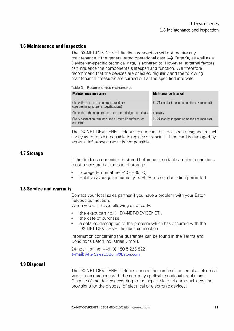
The DX-NET-DEVICENET fieldbus connection will not require any maintenance if the general rated operational data (→ Page 9), as well as all DeviceNet-specific technical data, is adhered to. However, external factors can influence the components’s lifespan and function. We therefore recommend that the devices are checked regularly and the following maintenance measures are carried out at the specified intervals.
Table 3: Recommended maintenance
The DX-NET-DEVICENET fieldbus connection has not been designed in such a way as to make it possible to replace or repair it. If the card is damaged by external influences, repair is not possible.
1.7 StorageIf the fieldbus connection is stored before use, suitable ambient conditions must be ensured at the site of storage:
• Storage temperature: -40 - +85 °C,• Relative average air humidity: < 95 %, no condensation permitted.
1.8 Service and warrantyContact your local sales partner if you have a problem with your Eaton fieldbus connection.When you call, have following data ready:
• the exact part no. (= DX-NET-DEVICENET),• the date of purchase,• a detailed description of the problem which has occurred with the
DX-NET-DEVICENET fieldbus connection.
Information concerning the guarantee can be found in the Terms and Conditions Eaton Industries GmbH.
24-hour hotline: +49 (0) 180 5 223 822e-mail: [email protected]
1.9 DisposalThe DX-NET-DEVICENET fieldbus connection can be disposed of as electrical waste in accordance with the currently applicable national regulations. Dispose of the device according to the applicable environmental laws and provisions for the disposal of electrical or electronic devices.
Maintenance measures Maintenance interval
Check the filter in the control panel doors(see the manufacturer's specifications)
6 - 24 months (depending on the environment)
Check the tightening torques of the control signal terminals regularly
Check connection terminals and all metallic surfaces for corrosion
6 - 24 months (depending on the environment)
DX-NET-DEVICENET 02/14 MN04012005ZEN www.eaton.com 11

1 Device series
1.9 Disposal
12 DX-NET-DEVICENET 02/14 MN04012005ZEN www.eaton.com
2 Engineering
2.1 DeviceNet
2 Engineering
2.1 DeviceNetDeviceNet was developed by Rockwell Automation and ODVA (Open DeviceNet Vendors Association) as an open field bus standard based on the CAN protocol.
DeviceNet is an object-oriented bus system and works using a producer/consumer model.
DeviceNet‘s application layer uses the CIP protocol (Common Industrial Protocol). CIP defines the transfer of I/O data in real time via I/O messages(I/O messaging or implicit messaging), as well as the transfer of request and response data for configuration, diagnostic, and management purposes (explicit messaging). CIP is an object-oriented protocol and is typically used to network sensors, variable frequency drives, and actuators with higher-level automation devices (PLCs).
DeviceNet devices within a DeviceNet network can function as a client (master), server (slave), or both.
DeviceNet networks can support a maximum of 64 bus nodes.Baud rates of 125, 250, or 500 kBaud can be achieved (depending on the type of cable used).
DX-NET-DEVICENET 02/14 MN04012005ZEN www.eaton.com 13
2 Engineering
2.2 LED indicators
2.2 LED indicators
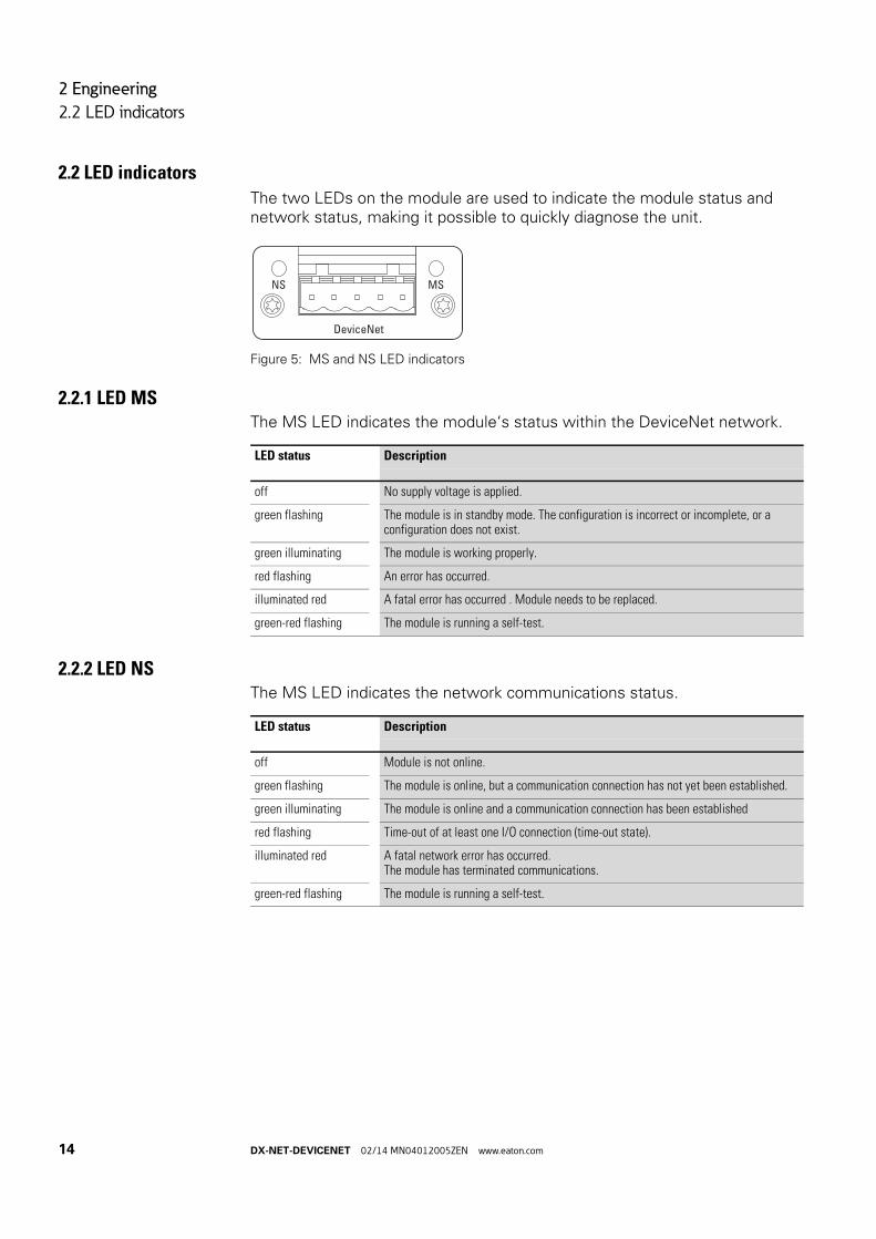
The two LEDs on the module are used to indicate the module status and network status, making it possible to quickly diagnose the unit.
Figure 5: MS and NS LED indicators
2.2.1 LED MSThe MS LED indicates the module‘s status within the DeviceNet network.
2.2.2 LED NSThe MS LED indicates the network communications status.
NS MS
DeviceNet
LED status Description
off No supply voltage is applied.
green flashing The module is in standby mode. The configuration is incorrect or incomplete, or a configuration does not exist.
green illuminating The module is working properly.
red flashing An error has occurred.
illuminated red A fatal error has occurred . Module needs to be replaced.
green-red flashing The module is running a self-test.
LED status Description
off Module is not online.
green flashing The module is online, but a communication connection has not yet been established.
green illuminating The module is online and a communication connection has been established
red flashing Time-out of at least one I/O connection (time-out state).
illuminated red A fatal network error has occurred.The module has terminated communications.
green-red flashing The module is running a self-test.
14 DX-NET-DEVICENET 02/14 MN04012005ZEN www.eaton.com

3 Installation
3.1 Introduction
3 Installation
3.1 IntroductionThis chapter provides a description of the mounting and the electrical connection for the fieldbus connection DX-NET-DEVICENET.
In the case of DA1 variable frequency drives, the way in which the DX-NET-DEVICENET fieldbus connection needs to be installed will depend on the corresponding variable frequency drive‘s size.
Figure 6: Flush mounting of fieldbus connection
In the case of DA1 variable frequency drives with sizes FS2 and FS3, the fieldbus connection will need to be plugged into the variable frequency drive from below. In the case of sizes FS4 and up, the fieldbus connection will need to be mounted on the right side, underneath the variable frequency drive's front enclosure cover.
→ While installing and/or mounting the fieldbus connection, cover all ventilation slots in order to ensure that no foreign bodies can enter the device.
→ Perform all installation work with the specified tools and without the use of excessive force.
L2/N L3DC-
L1/L
DC+ BR U V W
1 2 3 4 5 6 7 8 9 10 11 12 13
14 15 16 17 18
COM
11 12 13 14 15 16 17 18
NS
MS
DeviceNet
DX-NET-DEVICENET 02/14 MN04012005ZEN www.eaton.com 15

3 Installation
3.2 Notes on the documentation
3.2 Notes on the documentation
Documents containing installation instructions:
• IL4020010Z instruction leaflet for DA1 variable frequency drivein size FS2 and FS3
• IL4020011Z instruction leaflet for DA1 variable frequency drivefrom size FS4
These documents are also available as PDF files on the Eaton Internet website. They can be quickly located at
www.eaton.com/moeller → Support
by entering the document number as the search term.
3.3 Notes on the mechanical surface mounting
Figure 7: Make sure that the equipment is de-energizedwhen performing installation work
DANGER
Make sure that the equipment is fully de-energized when performing the handling and installation work required to mechanically set up and install the fieldbus connection.
→ When installing the DX-NET-DEVICENET fieldbus connection, it will be necessary to open the DA1 variable frequency drive‘s enclosure. We recommend that this mounting work be carried out before the electrical installation of the variable frequency drive.
L1/L L2/N L3
DC-
16 DX-NET-DEVICENET 02/14 MN04012005ZEN www.eaton.com

3 Installation
3.4 Mounting for frame sizes FS2 and FS3
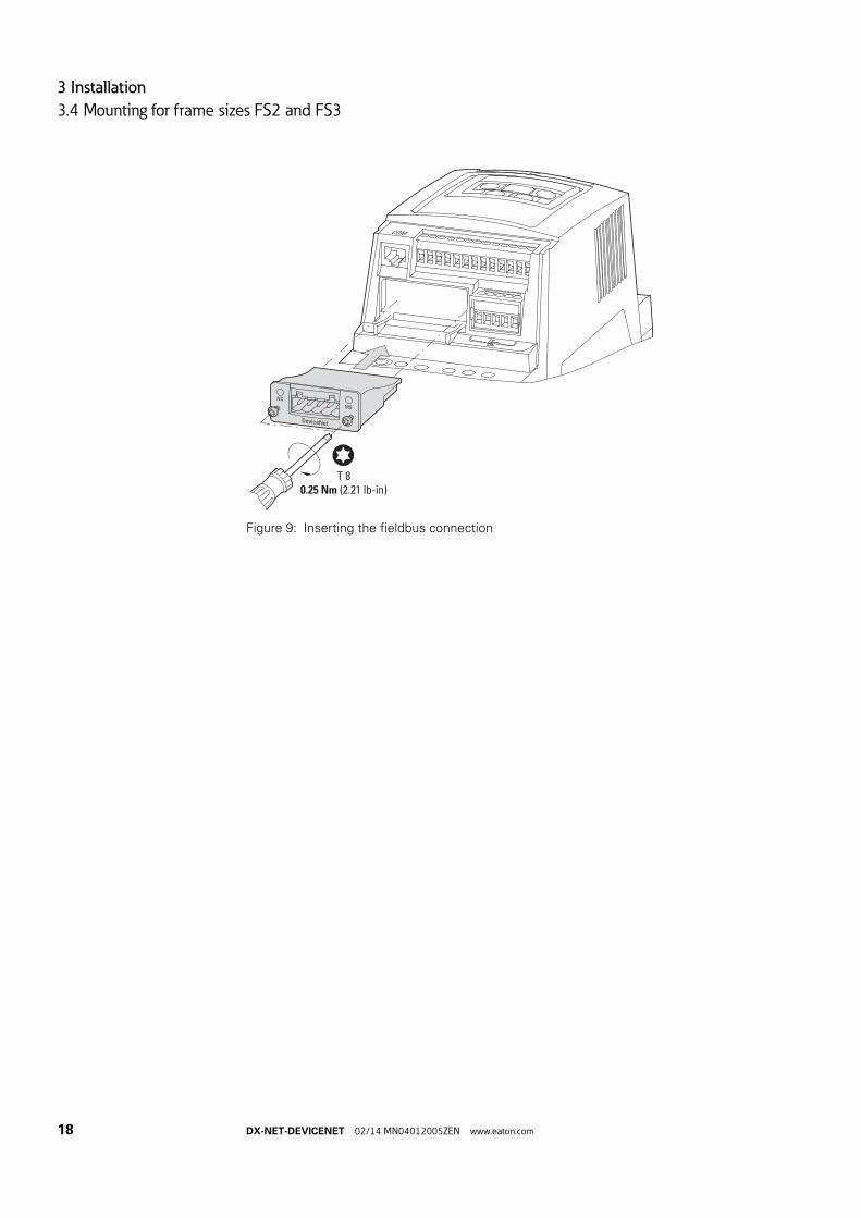
3.4 Mounting for frame sizes FS2 and FS3
In the case of DA1 variable frequency drives with sizes FS2 and FS3, the DX-NET-DEVICENET fieldbus connection needs to be installed on the bottom of the variable frequency drive. To do this, use a flat-blade screwdriver to lift off the cover at the marked cutout (without forcing it) and then remove the cover by hand.
Figure 8: Opening the interface cover
After doing so, you can insert the connection and secure it with the two screws.
NOTICE
Do not insert tools or other objects into the opened variable frequency drive.Ensure that foreign bodies do not enter the opened housing wall.
DC+ BR U V W
1 2 3 4 5 6 7 8 9 10 11 12 13
14 15 16 17 18
COM
4 mm
DX-NET-DEVICENET 02/14 MN04012005ZEN www.eaton.com 17
3 Installation
3.4 Mounting for frame sizes FS2 and FS3
Figure 9: Inserting the fieldbus connection
NS
MS
DeviceNet
T 80.25 Nm (2.21 lb-in)
COM
18 DX-NET-DEVICENET 02/14 MN04012005ZEN www.eaton.com
3 Installation
3.5 Mounting from frame size FS4
3.5 Mounting from frame size FS4
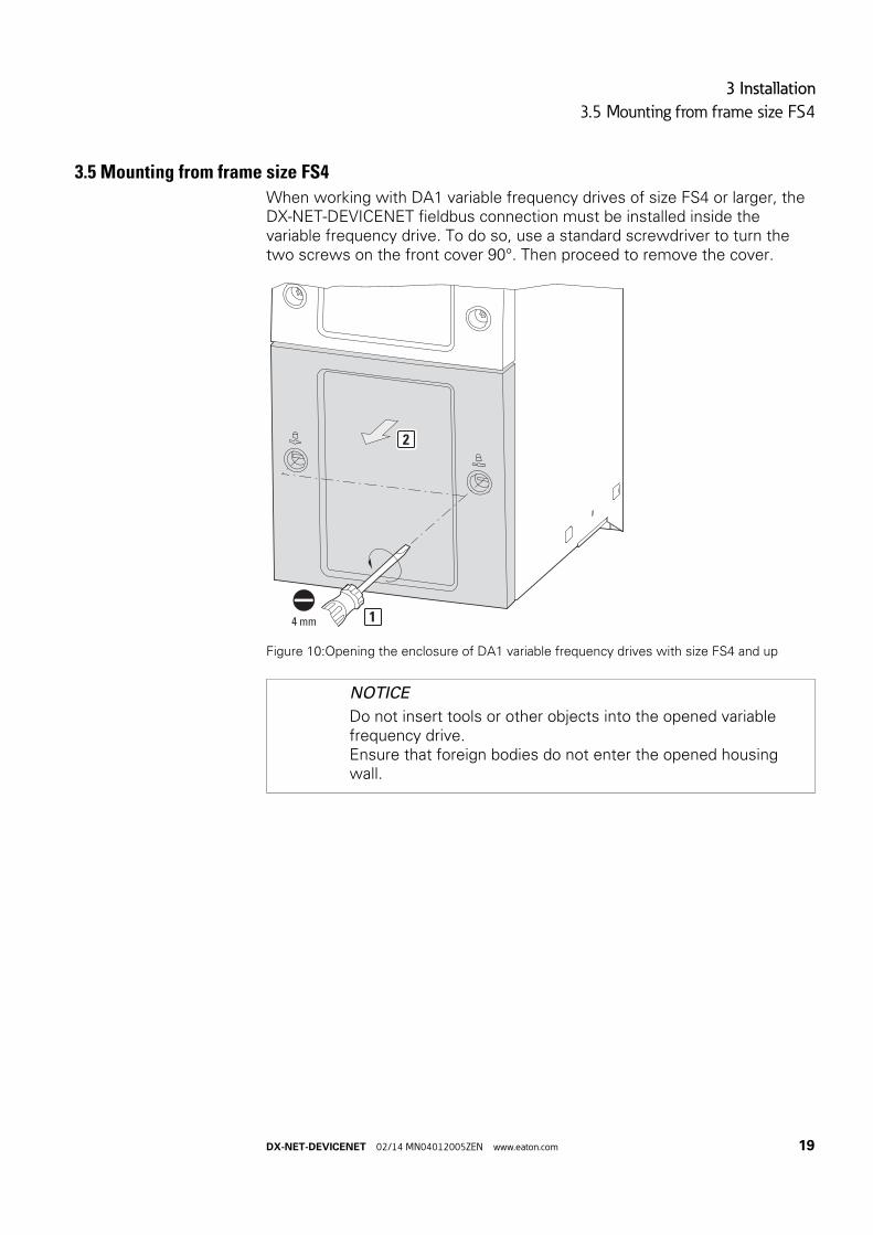
When working with DA1 variable frequency drives of size FS4 or larger, the DX-NET-DEVICENET fieldbus connection must be installed inside the variable frequency drive. To do so, use a standard screwdriver to turn the two screws on the front cover 90°. Then proceed to remove the cover.
Figure 10:Opening the enclosure of DA1 variable frequency drives with size FS4 and up
NOTICE
Do not insert tools or other objects into the opened variable frequency drive.Ensure that foreign bodies do not enter the opened housing wall.
4 mm 1
2
DX-NET-DEVICENET 02/14 MN04012005ZEN www.eaton.com 19

3 Installation
3.5 Mounting from frame size FS4
After doing so, you can insert the connection on the right-hand side and use the screws to secure it.
Then put the cover back on and use the two screws (turn them 90°) to secure it.
Figure 11:Inserting the fieldbus connection
1 2 3 4 5 6 7 8 9 10 11 12 13 14 15 16 17 18
L1 L2 L3 +DC BR -DC U V W
COM
1
2
T 80.25 Nm
(2.21 lb-in)
20 DX-NET-DEVICENET 02/14 MN04012005ZEN www.eaton.com

3 Installation
3.6 Installing the fieldbus connection
3.6 Installing the fieldbus connection
To connect the variable frequency drive to the DX-NET-DEVICENET field bus module, you will need a 5-pin DeviceNet plug with an appropriate prefabricated DeviceNet cable.
3.6.1 Pin assignment
Table 4: DeviceNet pin assignment
In order to ensure that all DeviceNet field bus communications will work properly, all the plug pins need to be connected. This applies to the 24-V bus voltage as well. If there is no bus voltage present, the DX-NET-DEVICENET module will be unable to communicate. In this case, the network status LED will be in the OFF mode.
→ DeviceNet plugs and DeviceNet cables are specified by ODVA. Make sure to only use cables specifically approved for use with DeviceNet!
The type of cable has an influence on the maximum available length of the bus line and thus also on the Baud rate (→ Table 5).
COM
NS
MS
DeviceNet
T 8
Assignment Pin Description
1 V-
2 CAN_L
3 Shield
4 CAN_H
5 V+ (24V)
1
2
3
4
5
1
2
3
4
5
V–
CAN_L
Shield
CAN_H
V+ (24 V)
DX-NET-DEVICENET 02/14 MN04012005ZEN www.eaton.com 21

3 Installation
3.6 Installing the fieldbus connection
3.6.2 Bus termination resistorThe first and last modules on a DeviceNet network must be terminated with a 120 Ω bus termination resistor. This resistor needs to be connected between CAN_H and CAN_L.
Figure 12:Bus termination resistors RT: CAN_H and CAN_L terminals
3.6.3 Max. cable lengthsThe maximum bus cable length depends not only on the data rate, but also on the type of cable being used. The following cable types are permitted:
• A so-called “Thick Cable”,• a so-called “Thin Cable”,• a so-called “Flat Cable”,
Table 5: Maximum length for specific DeviceNet cables
0 1 n . . .
RTRT
Baud rate Maximum cable length [m]
[Kbit/s] “Thick Cable” “Thin Cable” “Flat Cable”
125 500 100 420
250 250 100 200
500 100 100 100
22 DX-NET-DEVICENET 02/14 MN04012005ZEN www.eaton.com

3 Installation
3.7 Install field bus
3.7 Install field bus
When installing the connection, make sure that the control and signal cables(0 - 10 V, 4 - 20 mA, 24 V DC, etc.), as well as the field bus system‘s DeviceNet connection cables, are not routed directly parallel to mains connection or motor connection cables conveying power.
With parallel cable routing, the clearances between control, signal and field bus cables ② and energy-carrying mains and motor cables ① must be greater than 30 cm. Cables should always intersect at right angles.
Figure 13:Routing cables for DeviceNet ② andmains/motor cables ①
If the system requires a parallel routing in cable ducts, a partition must be installed between the field bus cable ② and the mains and motor cable ①, in order to prevent electromagnetic interference on the field bus.
Figure 14:Separate routing in the cable duct
a Mains and motor connection cable
b DeviceNet cable
→ Never lay the cable of a field bus system directly parallel to the energy carrying cables.
→ In all cases only use approved DeviceNet cables.
≧ 300 mm
(≧ 11.81“)
② ①
abab
DX-NET-DEVICENET 02/14 MN04012005ZEN www.eaton.com 23

3 Installation
3.7 Install field bus
24 DX-NET-DEVICENET 02/14 MN04012005ZEN www.eaton.com

4 Commissioning
4.1 DA1 variable frequency drives
4 Commissioning
4.1 DA1 variable frequency drives
4.2 EDS fileThe properties of a DeviceNet module are described in what is referred to as an EDS file. In order to be able to connect a DA1 variable frequency drive to a DeviceNet network, you will need the corresponding EDS file.
4.3 AddressingEach DeviceNet module requires its own unique address (MAC ID) within the DeviceNet network. A DeviceNet network can support up to 64 addresses (0 to 63). To set DeviceNet addresses, you will need to use the configuration software for the master controller you are using (this may require the use of an explicit message). To do so, use the corresponding service from the DeviceNet object.
→ First of all complete all measures for commissioning the DA1 variable frequency drive as described in the respective manual MN04020005Z-DE.
→ Check the settings and installations for the connection to the DeviceNet field bus system which are described in this manual.
NOTICE
Make sure that there is no danger in starting the motor.Disconnect the driven machine if there is a danger in an incorrect operating state.
→ For communications, parameter P12 (drive control) must be set as follows in the DA1 variable frequency drive:P12 = 4, P5-01 = 0 - 63
For detailed information on how to configure parameters, please refer to manual MN04020005Z-EN.
→ The EDS file can be found on the CD-ROM and on the Internet at:
www.eaton.com/moeller → Downloads
→ The MAC address will be printed on the corresponding nameplate. The DHCP function will be enabled by default.
DX-NET-DEVICENET 02/14 MN04012005ZEN www.eaton.com 25

4 Commissioning
4.4 Engineering the module
4.4 Engineering the module
The following instructions explain how to configure the communication module with a DA1 variable frequency drive.
Figure 15:Engineering
a PC (with configuration tool)
b Head-end controller
c Variable frequency drive DA1 with DX-NET-DEVICENET connection
d Motor
L1/L L2/N L3DC-
UDC+ BR
1 2 3 4 5 6 7 8 9 10 11 12 13
14 15 16 17 18
COM
V W
①
②
③
④
26 DX-NET-DEVICENET 02/14 MN04012005ZEN www.eaton.com
4 Commissioning
4.4 Engineering the module
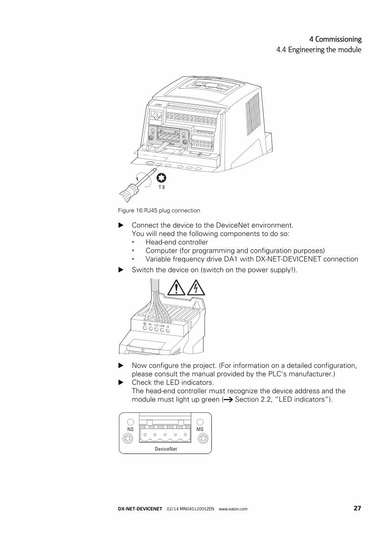
Figure 16:RJ45 plug connection
▶ Connect the device to the DeviceNet environment. You will need the following components to do so:• Head-end controller• Computer (for programming and configuration purposes)• Variable frequency drive DA1 with DX-NET-DEVICENET connection
▶ Switch the device on (switch on the power supply!).
▶ Now configure the project. (For information on a detailed configuration, please consult the manual provided by the PLC‘s manufacturer.)
▶ Check the LED indicators.The head-end controller must recognize the device address and the module must light up green (→ Section 2.2, “LED indicators“).
COM
NS
MS
DeviceNet
T 8
L1/L L2/N L3
DC-
NS MS
DeviceNet
DX-NET-DEVICENET 02/14 MN04012005ZEN www.eaton.com 27

4 Commissioning
4.5 General information about the DeviceNet field bus system
4.5 General information about the DeviceNet field bus system
The DeviceNet field bus system is based on a connection-oriented communications model. In other words, data can only be exchanged using specific connections assigned to the devices.
4.5.1 Object modelIn DeviceNet, all the devices within a DeviceNet network are described with a unique object model. Each specific device is defined with the help of objects.
The object model's objects can be subdivided into three groups:
• Management objects,• Connection objects,• Application-specific objects.
4.5.1.1 Management objectsManagement objects define DeviceNet-specific data and functions.Every single DeviceNet device has to support these objects.
Identity Object
The Identity Object (Class Code 01hex) contains all the data required to uniquely identify a node within the network, e.g., vendor ID, device type, and product code. In addition, it contains a device's current status, serial number, and product name.
Message Router Object
The Message Router Object (Class Code 02hex) provides access to all of a device's classes and instances via explicit messages.
4.5.1.2 Connection ObjectsConnection objects define the messages exchanged via DeviceNet.
DeviceNet Object
The DeviceNet Object (Class Code 03hex) specifies the configuration of a device, as well as its physical connection to the DeviceNet network. Every single device has to support this object. More specifically, the object contains the device's MAC ID, its current configured baud rate, and other pertinent information.
Connection Object
The Connection Object (Class Code 0x05hex) is supported by every single DeviceNet device in at least one instance. This object defines the connection to data via I/O messages or explicit messages, the path and length of producer/consumer data, the CAN identifier used for the connection, the corresponding watchdog timer, and the response in the event of a fault scenario.
28 DX-NET-DEVICENET 02/14 MN04012005ZEN www.eaton.com

4 Commissioning
4.6 Supported objects
4.5.1.3 Application-specific objectsApplication-specific objects are used to define device-specific data and functions.
Application Objects
Application objects describe simple automation applications. They are either predefined in the DeviceNet Object Library or are defined by the user.
Parameter Object
The Parameter Object (Class Code 0Fhex) serves as an interface to a device‘s configuration data and parameters. It contains an instance for each parameter, with the instance being linked to the parameter to be configured.
Assembly Object
The Assembly Object (Class Code: 04hex) provides the user with mapping options, i.e. attribute data of different instances in different classes can be grouped together to form a single attribute of an instance in an assembly object.
Acknowledge Handler Object
The Acknowledge Handler Object (Class Code 2Bhex) makes it possible to establish acknowledged connections, as well as COS and cyclic I/O connections.
ADI Object
The ADI Object (Class Code A2hex) provides access to the DA1 variable frequency drive's acyclic data.
4.6 Supported objectsThe DX-NET-DEVICENET module uses the following DeviceNet object classes as defined in the “Communications Adapter Profile” device profile(as per ODVA specifications):
• Identity Object (01hex)• DeviceNet Object (03hex)• Connection Object (05hex)• Parameter Object (0Fhex)• Acknowledge Handler Object (2Bhex)• ADI Object (A2hex)
DX-NET-DEVICENET 02/14 MN04012005ZEN www.eaton.com 29

4 Commissioning
4.6 Supported objects
4.6.1 Identity Object (01hex)The Identity Object (Class Code 01hex) contains all the data required in order to uniquely identify a network node.
The Identity Object supports the following services:
Table 6: Services
Attribute Id
Name Access Data type Description or Value
1 Vendor ID ro UINT Vendor identification number = 248decThe ODVA specifies the Vendor ID. This is 248dec for Eaton GmbH.
2 Device type ro UINT Device type (product type) = Communications adapter
3 Product Code ro UINT 69123decEaton GmbH has defined the following product code (used to identify specific vendor products) for the module: 69123dec. It makes reference to the model number.
4 Revision ro USINT Device versionTwo bytes are returned when the device version is read.
Major Revision ro USINT The low byte defines the hardware version, the high byte the operating system version.
Minor Revision ro USINT
5 status ro WORD The device‘s status
6 Serial Number ro UDINT Device serial number
7 Product Name ro SHORT_STRING
DX-NET-DEVICENET
Service code
Service name Description
05hex Reset Calls the module's reset function.
OEhex Get_Attribute_Single This service can be used to read the value of a selected attribute from the module.
10hex Set_Attribute_Single This service can be used to set a selected attribute in the module.
30 DX-NET-DEVICENET 02/14 MN04012005ZEN www.eaton.com

4 Commissioning
4.6 Supported objects
4.6.2 DeviceNet Object (03hex)The DeviceNet Object can be used to configure the DX-NET-DEVICENET communications module and to define the corresponding physical environment.
Class Attributes
Instance attributes
Services
Attribute number
Attribute name Access right
ro | rw
Data type Description
1 Revision ro UINT Object revision
Attribute Id
Name Access Data type Description (Value)
1 MAC ID ro USINT Network address of a network node.
2 Baud rate ro USINT Baud rate during communications
3 BOIBus-Off-Interrupt
ro/rw BOOL Response in the event of a bus-off event (FALSE)
4 Bus-Off Counter ro/rw USINT Number (value range: 0 - 255) of bus-off events
5 Allocation Information
ro STRUCT of BYTE, USINT
Selection bit used to assign the master MAC ID
6 MAC-IDSwitch changed
ro BOOL The MAC ID switch settings have changed (since the last time the module was switched on)
7 Baud RateSwitch changed
ro BOOL
8 MAC-IDSwitch Value
ro USINT Current Value
9 Baud RateSwitch Value
ro USINT Current Value
Service code
Service name Description
OEhex Get_Attribute_Single This service can be used to read the value of a selected attribute from the module.
10hex Set_Attribute_Single This service can be used to set a selected attribute in the module.
4Bhex Allocate_Master/Slave_Connection_Set
Requests the predefined master/slave connection set.
4Chex Release_Group_2_Identifier_Set
Releases connections in the master/slave connection set.
DX-NET-DEVICENET 02/14 MN04012005ZEN www.eaton.com 31

4 Commissioning
4.6 Supported objects
4.6.3 ADI Object (A2hex)In addition to standard object classes, there are also vendor-specific classes that make it possible to access individual variable frequency drive properties. Object class A2h is used for this purpose.
The A2h object can be used to access the DA1 variable frequency drive‘s acyclic data.
Class Attributes
Instance attributes
Class Property Name Description
A2h ADI Variable frequency drive data for access to acyclic data
Classes/Instances Attribute/Services Value
Classes
Attributes 0x01, 0x02, 0x03
Services 0xE
Instances
Attributes 1, 2, 3, 4, 5, 6, 7, 8
Services 0xE
Attribute Id Attribute name Access rightsro | rw
Data type Description Value
1 CLASS REVISION ro UINT version 0x00 01
2 MAX OBJECT INSTANCE ro UINT Maximum number of object instances –
3 NUMBER OF INSTANCES ro UINT maximum number of instances –
Attribute Id
Attribute name Access rightsro | rw
Data type Description
1 Name ro Short_String Parameter name with length
2 Data Type ro USINT Data type of the instance value
3 No. of elements ro USINT Number of elements for the specified data types
4 Descriptor ro USINT Access rights for the instanceBit meaning: kit0 = Get Access1 = Set Access
5 Value rw Defined by attribute 2
Instance value
6 Max Value ro Maximum permitted parameter value
7 Min Value ro Minimum permitted parameter value
8 Default Value ro Default parameter value (default setting)
32 DX-NET-DEVICENET 02/14 MN04012005ZEN www.eaton.com

4 Commissioning
4.6 Supported objects
4.6.4 Connection Object (05hex)The Connection Object (Class Code 05hex) is supported by every single DeviceNet device in at least one instance. This object defines the connection to data via I/O messages or explicit messages, the path and length of producer/consumer data, the CAN identifier used for the connection, the corresponding watchdog timer, and the response in the event of a fault scenario.
Class Attributes
Explicit Messages
Explicit messages are used to transmit low-priority configuration data, general management data and diagnostic data between two specific devices. They are always sent using a point-to-point connection in a client/server system, which means that a client request must always be followed by a server response.
Instance attributes
Table 7: Instance 1: Explicit message connection
Attribute Id
Attribute name Access right
ro | rw
Data type Description
1 Revision ro UINT Object revision
Attribute Id
Attribute name Access right
ro | rw
Data type Description
1 State ro USINT Connection status.0: Non existent1: Configuring2: Waiting for connection ID3: Established4: Time out5: Deferred
2 Instance Type ro USINT Indicates explicit messaging.
3 Transport Class Trigger ro Byte Type of connection
4 Produced Connection ID ro UINT
5 Consumed Connection ID ro UINT
6 Initial Communication Characteristics
ro Byte
7 Produced Connection Size ro UINT The maximum number of bytes that will be sent (262 bytes)
8 Consumed Connection Size ro UINT The maximum number of bytes that will be received (262 bytes)
9 Expected Packet Rate ro/rw UINT Time behavior
12 Watchdog Timeout Action ro/rw USINT Timeout Time
DX-NET-DEVICENET 02/14 MN04012005ZEN www.eaton.com 33
4 Commissioning
4.6 Supported objects
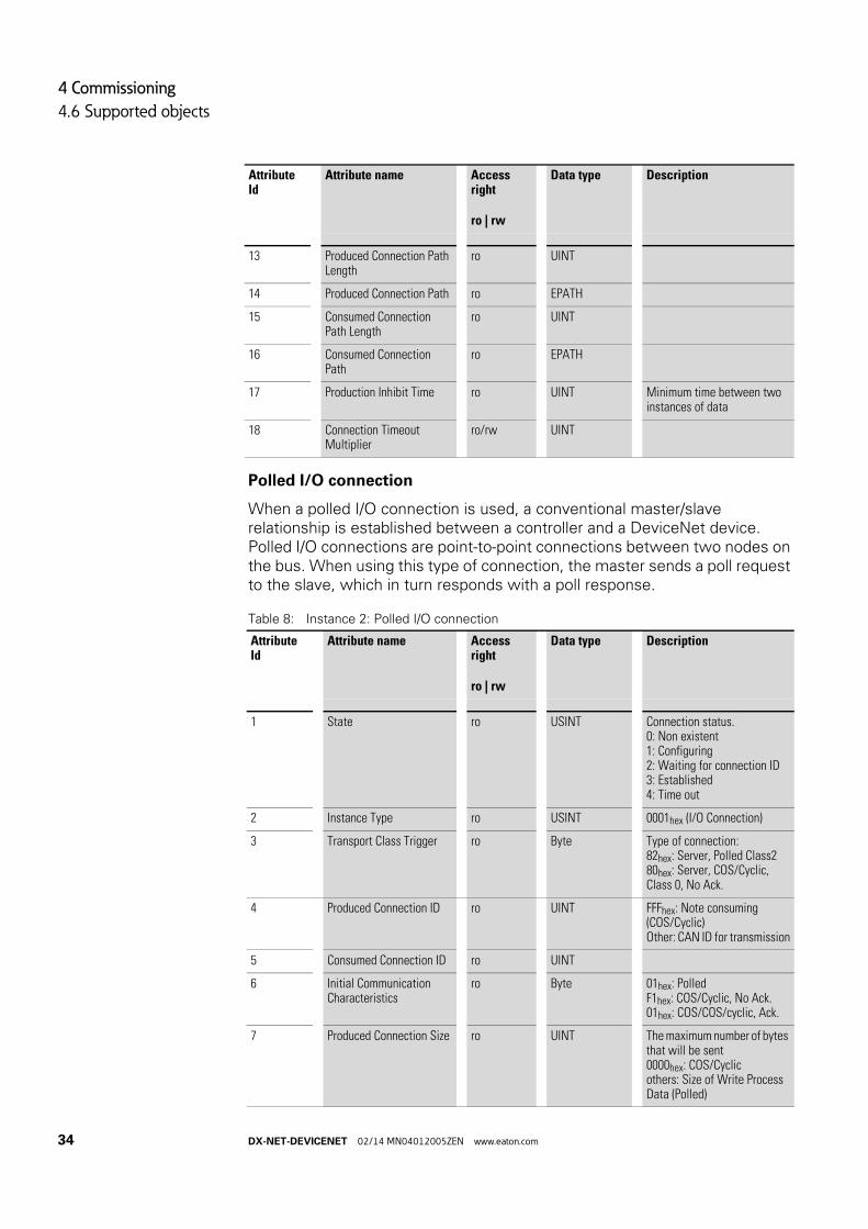
Polled I/O connection
When a polled I/O connection is used, a conventional master/slave relationship is established between a controller and a DeviceNet device. Polled I/O connections are point-to-point connections between two nodes on the bus. When using this type of connection, the master sends a poll request to the slave, which in turn responds with a poll response.
Table 8: Instance 2: Polled I/O connection
13 Produced Connection Path Length
ro UINT
14 Produced Connection Path ro EPATH
15 Consumed Connection Path Length
ro UINT
16 Consumed Connection Path
ro EPATH
17 Production Inhibit Time ro UINT Minimum time between two instances of data
18 Connection Timeout Multiplier
ro/rw UINT
Attribute Id
Attribute name Access right
ro | rw
Data type Description
1 State ro USINT Connection status.0: Non existent1: Configuring2: Waiting for connection ID3: Established4: Time out
2 Instance Type ro USINT 0001hex (I/O Connection)
3 Transport Class Trigger ro Byte Type of connection:82hex: Server, Polled Class280hex: Server, COS/Cyclic, Class 0, No Ack.
4 Produced Connection ID ro UINT FFFhex: Note consuming(COS/Cyclic)Other: CAN ID for transmission
5 Consumed Connection ID ro UINT
6 Initial Communication Characteristics
ro Byte 01hex: PolledF1hex: COS/Cyclic, No Ack.01hex: COS/COS/cyclic, Ack.
7 Produced Connection Size ro UINT The maximum number of bytes that will be sent0000hex: COS/Cyclicothers: Size of Write Process Data (Polled)
Attribute Id
Attribute name Access right
ro | rw
Data type Description
34 DX-NET-DEVICENET 02/14 MN04012005ZEN www.eaton.com

4 Commissioning
4.6 Supported objects
8 Consumed Connection Size
ro UINT The maximum number of bytes that will be received
9 Expected Packet Rate ro/rw UINT Time behavior
12 Watchdog Timeout Action ro/rw USINT 0000hex(transition to the timed out state)
13 Produced Connection Path Length
ro UINT 0000hex (COS/Cyclic)0007hex (Polled)
14 Produced Connection Path ro EPATH No Value (COS/Cyclic)20 04 25 nn nn 30 03hex (Polled)
15 Consumed Connection Path Length
ro UINT 0007hex
16 Consumed Connection Path
ro EPATH 20 04 25 nn nn 30 03hex
17 Production Inhibit Time ro UINT 0000hexMinimum time between two instances of data
18 Connection Timeout Multiplier
ro/rw UINT 0000hex
Attribute Id
Attribute name Access right
ro | rw
Data type Description
DX-NET-DEVICENET 02/14 MN04012005ZEN www.eaton.com 35
4 Commissioning
4.6 Supported objects
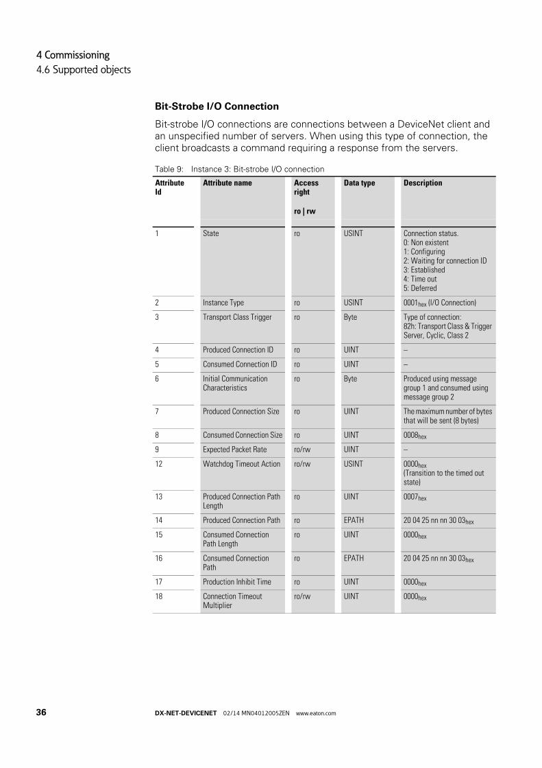
Bit-Strobe I/O Connection
Bit-strobe I/O connections are connections between a DeviceNet client and an unspecified number of servers. When using this type of connection, the client broadcasts a command requiring a response from the servers.
Table 9: Instance 3: Bit-strobe I/O connection
Attribute Id
Attribute name Access right
ro | rw
Data type Description
1 State ro USINT Connection status.0: Non existent1: Configuring2: Waiting for connection ID3: Established4: Time out5: Deferred
2 Instance Type ro USINT 0001hex (I/O Connection)
3 Transport Class Trigger ro Byte Type of connection:82h: Transport Class & Trigger Server, Cyclic, Class 2
4 Produced Connection ID ro UINT –
5 Consumed Connection ID ro UINT –
6 Initial Communication Characteristics
ro Byte Produced using message group 1 and consumed using message group 2
7 Produced Connection Size ro UINT The maximum number of bytes that will be sent (8 bytes)
8 Consumed Connection Size ro UINT 0008hex
9 Expected Packet Rate ro/rw UINT –
12 Watchdog Timeout Action ro/rw USINT 0000hex(Transition to the timed out state)
13 Produced Connection Path Length
ro UINT 0007hex
14 Produced Connection Path ro EPATH 20 04 25 nn nn 30 03hex
15 Consumed Connection Path Length
ro UINT 0000hex
16 Consumed Connection Path
ro EPATH 20 04 25 nn nn 30 03hex
17 Production Inhibit Time ro UINT 0000hex
18 Connection Timeout Multiplier
ro/rw UINT 0000hex
36 DX-NET-DEVICENET 02/14 MN04012005ZEN www.eaton.com
4 Commissioning
4.6 Supported objects
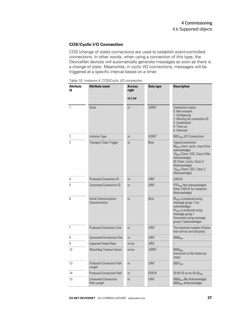
COS/Cyclic I/O Connection
COS (change of state) connections are used to establish event-controlled connections. In other words, when using a connection of this type, the DeviceNet devices will automatically generate messages as soon as there is a change of state. Meanwhile, in cyclic I/O connections, messages will be triggered at a specific interval based on a timer.
Table 10: Instance 4: COS/Cyclic I/O connection
Attribute Id
Attribute name Access right
ro | rw
Data type Description
1 State ro USINT Connection status.0: Non existent1: Configuring2: Waiting for connection ID3: Established4: Time out5: Deferred
2 Instance Type ro USINT 0001hex (I/O Connection)
3 Transport Class Trigger ro Byte Type of connection: 00hex client, cyclic, class 0 (no acknowledge)10hex Client, COS, Class 0 (No Acknowledge)02 Client, Cyclic, Class 2 (Acknowledge)12hex Client, COS, Class 2 (Acknowledge)
4 Produced Connection ID ro UINT CAN ID
5 Consumed Connection ID ro UINT FFFFhex Not acknowledgedOther CAN ID for reception (Acknowledge)
6 Initial Communication Characteristics
ro Byte 0Fhex is produced using message group 1 (no acknowledge)01hex is produced using message group 1Consumed using message group 2 (acknowledge)
7 Produced Connection Size ro UINT The maximum number of bytes that will be sent (8 bytes)
8 Consumed Connection Size ro UINT 0008hex
9 Expected Packet Rate ro/rw UINT –
12 Watchdog Timeout Action ro/rw USINT 0000hex(transition to the timed out state)
13 Produced Connection Path Length
ro UINT 0007hex
14 Produced Connection Path ro EPATH 20 04 25 nn nn 30 03hex
15 Consumed Connection Path Length
ro UINT 0000hex (No Acknowledge)0005hex (Acknowledge)
DX-NET-DEVICENET 02/14 MN04012005ZEN www.eaton.com 37

4 Commissioning
4.6 Supported objects
4.6.4.1 Acknowledge Handler Object (2Bhex)The Acknowledge Handler Object (Class Code 2Bhex) can be used to communicate with an application object within the device.
Class Attributes
Instance attributes
16 Consumed Connection Path
ro EPATH No Value (No. Acknowledge)20 2B 01 00hex (Acknowledge)
17 Production Inhibit Time ro UINT 0000hex
18 Connection Timeout Multiplier
ro/rw UINT 0000hex
Attribute Id
Attribute name Access right
ro | rw
Data type Description
Attribute Id
Attribute name Access right
ro | rw
Data type Value Description
1 Revision ro UINT 0001h Revision
Attribute Id
Attribute name Access right
ro | rw
Data type Value Description
1 Acknowledged Timer
ro/rw UINT 16 ms Waiting time in milliseconds
2 Retry Limit ro/rw USINT 01h Number of acknowledged timeout errors
3 Producing Connection Instance
ro UINT 04h Connection instance ID
38 DX-NET-DEVICENET 02/14 MN04012005ZEN www.eaton.com
4 Commissioning
4.6 Supported objects
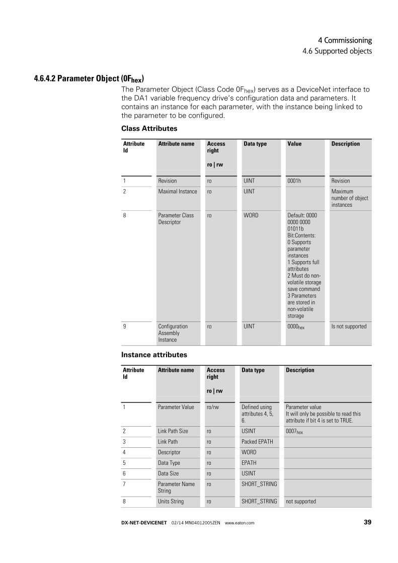
4.6.4.2 Parameter Object (0Fhex)The Parameter Object (Class Code 0Fhex) serves as a DeviceNet interface to the DA1 variable frequency drive‘s configuration data and parameters. It contains an instance for each parameter, with the instance being linked to the parameter to be configured.
Class Attributes
Instance attributes
Attribute Id
Attribute name Access right
ro | rw
Data type Value Description
1 Revision ro UINT 0001h Revision
2 Maximal Instance ro UINT Maximum number of object instances
8 Parameter Class Descriptor
ro WORD Default: 0000 0000 0000 01011bBit:Contents:0 Supports parameter instances1 Supports full attributes2 Must do non-volatile storage save command3 Parameters are stored in non-volatile storage
9 Configuration Assembly Instance
ro UINT 0000hex Is not supported
Attribute Id
Attribute name Access right
ro | rw
Data type Description
1 Parameter Value ro/rw Defined using attributes 4, 5, 6.
Parameter valueIt will only be possible to read this attribute if bit 4 is set to TRUE.
2 Link Path Size ro USINT 0007hex
3 Link Path ro Packed EPATH
4 Descriptor ro WORD
5 Data Type ro EPATH
6 Data Size ro USINT
7 Parameter Name String
ro SHORT_STRING
8 Units String ro SHORT_STRING not supported
DX-NET-DEVICENET 02/14 MN04012005ZEN www.eaton.com 39

4 Commissioning
4.6 Supported objects
9 Help String ro SHORT_STRING not supported
10 Minimum Value ro Minimum parameter value
11 Maximum Value ro Maximum parameter value
12 Default Value ro Default settings
13 Scaling Multiplier ro UINT 0001hex (not supported in this case)
14 Scaling Divisor ro UINT 0001hex (not supported in this case)
15 Scaling Base ro UINT 0001hex (not supported in this case)
16 Scaling Offset ro INT 0000h (not supported in this case)
17 Multiplier Link ro UINT 0000hex (not supported in this case)
18 Divisor Link ro UINT 0000hex (not supported in this case)
19 Base Link ro UINT 0000hex (not supported in this case)
20 Offset Link ro UINT 0000hex (not supported in this case)
21 Decimal precision ro USINT 0000hex (not supported in this case)
Attribute Id
Attribute name Access right
ro | rw
Data type Description
40 DX-NET-DEVICENET 02/14 MN04012005ZEN www.eaton.com
4 Commissioning
4.7 Operation
4.7 Operation
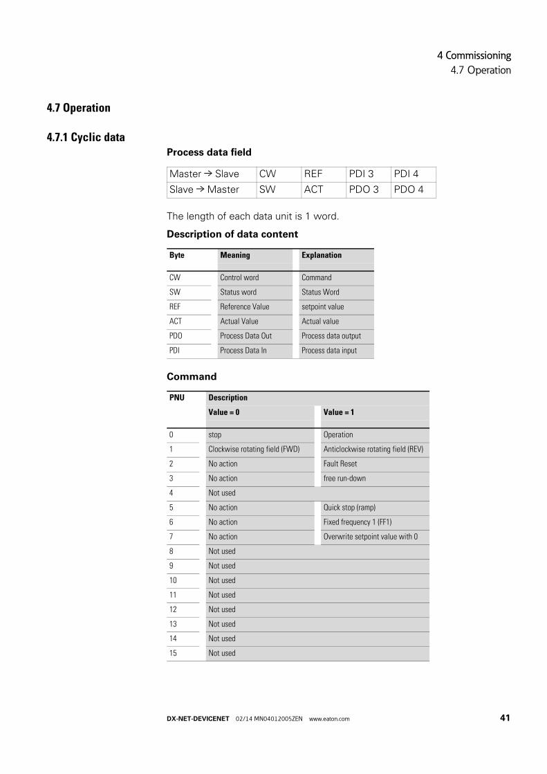
4.7.1 Cyclic dataProcess data field
The length of each data unit is 1 word.
Description of data content
Command
Master → Slave CW REF PDI 3 PDI 4
Slave → Master SW ACT PDO 3 PDO 4
Byte Meaning Explanation
CW Control word Command
SW Status word Status Word
REF Reference Value setpoint value
ACT Actual Value Actual value
PDO Process Data Out Process data output
PDI Process Data In Process data input
PNU Description
Value = 0 Value = 1
0 stop Operation
1 Clockwise rotating field (FWD) Anticlockwise rotating field (REV)
2 No action Fault Reset
3 No action free run-down
4 Not used
5 No action Quick stop (ramp)
6 No action Fixed frequency 1 (FF1)
7 No action Overwrite setpoint value with 0
8 Not used
9 Not used
10 Not used
11 Not used
12 Not used
13 Not used
14 Not used
15 Not used
DX-NET-DEVICENET 02/14 MN04012005ZEN www.eaton.com 41
4 Commissioning
4.7 Operation
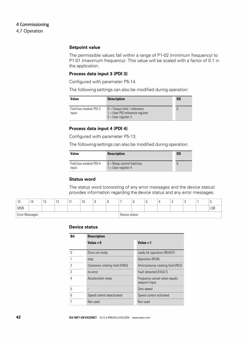
Setpoint value
The permissible values fall within a range of P1-02 (minimum frequency) to P1-01 (maximum frequency). This value will be scaled with a factor of 0.1 in the application.
Process data input 3 (PDI 3)
Configured with parameter P5-14.
The following settings can also be modified during operation:
Process data input 4 (PDI 4)
Configured with parameter P5-13.
The following settings can also be modified during operation:
Status word
The status word (consisting of any error messages and the device status) provides information regarding the device status and any error messages.
Device status
Value Description DS
Field bus module PDI-3 input
0 = Torque limit / reference1 = User PID reference register2 = User register 3
0
Value Description DS
Field bus module PDI-4 input
0 = Ramp control field bus1 = User register 4
0
15 14 13 12 11 10 9 8 7 6 5 4 3 2 1 0
MSB LSB
Error Messages Device status
Bit Description
Value = 0 Value = 1
0 Drive not ready ready for operation (READY)
1 stop Operation (RUN)
2 Clockwise rotating field (FWD) Anticlockwise rotating field (REV)
3 no error Fault detected (FAULT)
4 Acceleration ramp Frequency actual value equals setpoint input
5 – Zero speed
6 Speed control deactivated Speed control activated
7 Not used Not used
42 DX-NET-DEVICENET 02/14 MN04012005ZEN www.eaton.com

4 Commissioning
4.7 Operation
Error messages
Failure code [hex]
Value shown on display
Meaning
00 no-fit Stop, ready for operation
01 OI-b Braking chopper overcurrent
02 OL-br Braking resistance overload
03 O-l • Overcurrent at variable frequency drive output• Motor overload• Overtemperature on variable frequency drive (heat sink)
04 I.t-trp Motor, thermal overload
05 SAFE -1 Short-circuit at safety circuit input
06 O Volts Overvoltage (DC link)
07 V-volts Undervoltage (DC link)
08 O-t Overtemperature (heat sink)
09 V-t Undertemperature (heat sink)
0A P-dEf Default settings, parameters have been loaded
0B E-trip External error message
0C SC-ObS Error, OP bus
0D FLt-dc Excessively large voltage waves in DC link
0E P-LOSS Phase failure (mains side)
0F h O-I Overcurrent at variable frequency drive output
10 th-Flt Thermistor fault, built-in (heat sink)
11 dAtA-F EEPROM checksum fault
12 4-20F Analog input:• out-of-range value• Wire breakage (4 mA monitoring)
13 dAtA- E Error in internal memory
14 V-dEF User-definable factory parameters have been loaded
15 F-Ptc Excessive overtemperature, motor PTC
16 FAN-F Fault, internal fan
17 O-hEAt Excessively high ambient air temperature
18 O-torq Maximum torque limit exceeded
19 V-torq Output torque too low
1A Out-F Fault at variable frequency drive output
1D SAFE-2 Short-circuit at safety circuit input
1D Enc-01 Encoder, communication lost
1F Enc-02 Encoder, speed error
20 Enc-03 Encoder, wrong PPRs set
21 Enc-04 Encoder, channel A fault
22 Enc-05 Encoder, channel B fault
23 Enc-06 Encoder, channel A and B fault
24 Enc-07 Encoder, RS485 data channel error
DX-NET-DEVICENET 02/14 MN04012005ZEN www.eaton.com 43
4 Commissioning
4.7 Operation
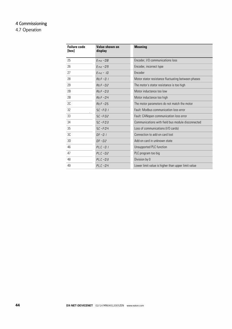
25 Enc-08 Encoder, I/O communications loss
26 Enc-09 Encoder, incorrect type
27 Enc-10 Encoder
28 AtF-01 Motor stator resistance fluctuating between phases
29 AtF-02 The motor's stator resistance is too high
2B AtF-03 Motor inductance too low
2B AtF-04 Motor inductance too high
2C AtF-05 The motor parameters do not match the motor
32 SC-FO1 Fault: Modbus communication loss error
33 SC-F02 Fault: CANopen communication loss error
34 SC-F03 Communications with field bus module disconnected
35 SC-F04 Loss of communications (I/O cards)
3C OF-01 Connection to add-on card lost
3D OF-02 Add-on card in unknown state
46 PLC-01 Unsupported PLC function
47 PLC-02 PLC program too big
48 PLC-03 Division by 0
49 PLC-04 Lower limit value is higher than upper limit value
Failure code [hex]
Value shown on display
Meaning
44 DX-NET-DEVICENET 02/14 MN04012005ZEN www.eaton.com
4 Commissioning
4.7 Operation
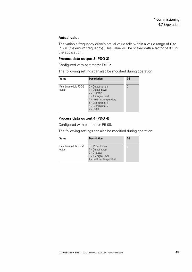
Actual value
The variable frequency drive's actual value falls within a value range of 0 to P1-01 (maximum frequency). This value will be scaled with a factor of 0.1 in the application.
Process data output 3 (PDO 3)
Configured with parameter P5-12.
The following settings can also be modified during operation:
Process data output 4 (PDO 4)
Configured with parameter P5-08.
The following settings can also be modified during operation:
Value Description DS
Field bus module PDO-3 output
0 = Output current1 = Output power2 = DI status3 = AI2 signal level4 = Heat sink temperature5 = User register 16 = User register 27 = P0-80
0
Value Description DS
Field bus module PDO-4 output
0 = Motor torque1 = Output power2 = DI status3 = AI2 signal level4 = Heat sink temperature
0
DX-NET-DEVICENET 02/14 MN04012005ZEN www.eaton.com 45

4 Commissioning
4.8 Parameter
4.8 Parameter
The abbreviations used in the parameter lists below have the following meaning:
Figure 17:How the parameters are shown in the manual and in the software
The Baud rate will automatically be set to match the master.
4.8.0.1 Acyclic ParametersThe module can be used to read and program parameters.
Access to the DA1 variable frequency drive‘s acyclic data is provided by object class A2h. The relevant ADI number can be found in → Table 11.
PNU Parameter number
ID Identification number of the parameter
RUN Access rights to the parameters during operation (RUN): / = Modification permissible- = Modification only possible in STOP
ro | rw Parameter read and write permissions via a fieldbus connection:ro = read onlyrw = read and write (read and write)
Value Setting of the parameter
DS Default setting: (P1.1 = 1) base parameter
→ Access rights are not shown in the drivesConnect PC software.
Manual
PNU ID Access right Value Description DS
RUN ro | rw
① ② ③ ④
PC Software
PNU Description Value Range Default Visible
① ③ ② ④
PNU ID Access right Designation Value range DS Value that must be configured
RUN ro | rw
P1-12 112 – rw Control level 0 = Control signal terminals (I/O)1 = Keypad (KEYPAD FWD)2 = Keypad (KEYPAD FWD/REV)3 = PID control4 = field bus system (PROFINET-2, Modbus RTU, etc.)5 = Slave mode6 = field bus CANopen
0 4
46 DX-NET-DEVICENET 02/14 MN04012005ZEN www.eaton.com
4 Commissioning
4.8 Parameter
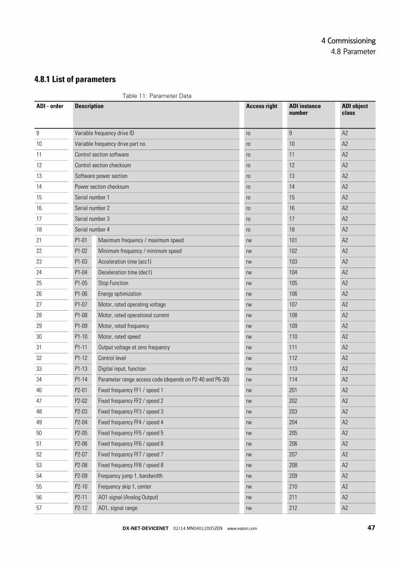
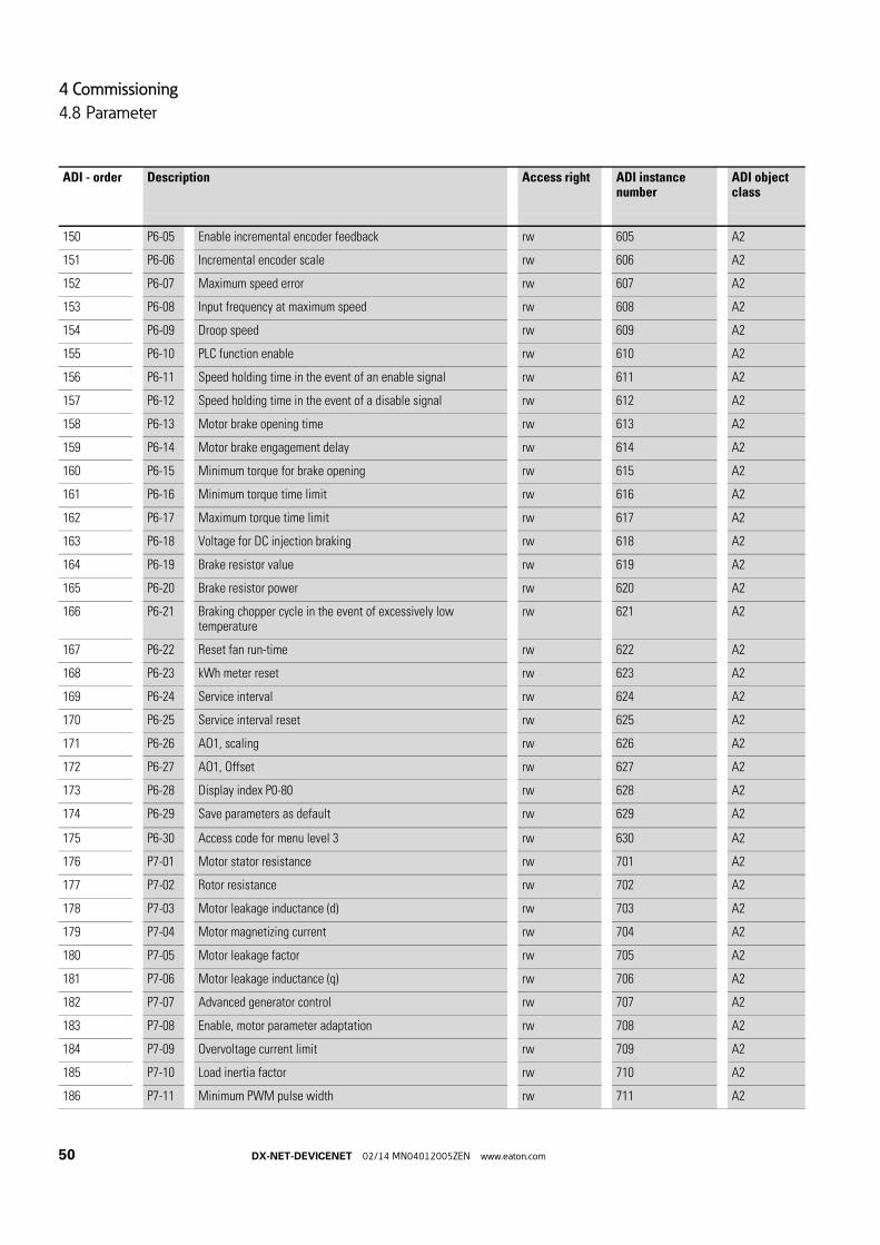
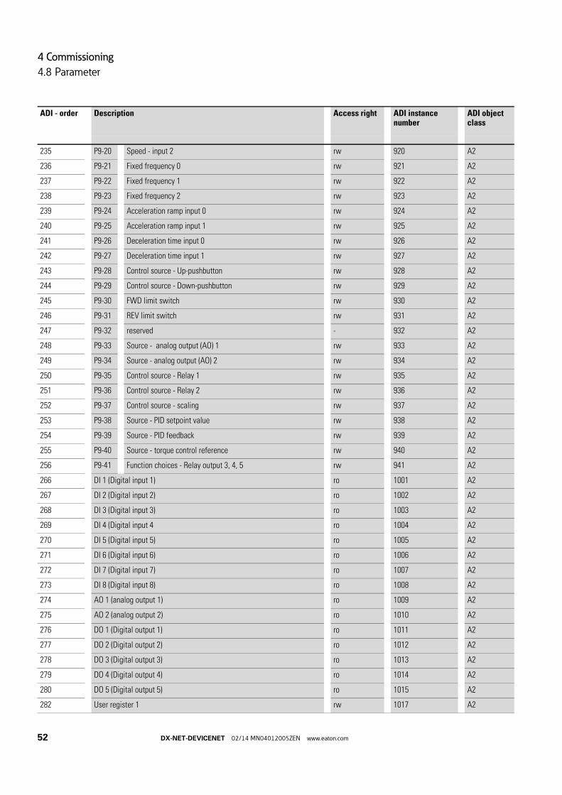
4.8.1 List of parameters
Table 11: Parameter Data
ADI - order Description Access right ADI instance number
ADI object class
9 Variable frequency drive ID ro 9 A2
10 Variable frequency drive part no. ro 10 A2
11 Control section software ro 11 A2
12 Control section checksum ro 12 A2
13 Software power section ro 13 A2
14 Power section checksum ro 14 A2
15 Serial number 1 ro 15 A2
16 Serial number 2 ro 16 A2
17 Serial number 3 ro 17 A2
18 Serial number 4 ro 18 A2
21 P1-01 Maximum frequency / maximum speed rw 101 A2
22 P1-02 Minimum frequency / minimum speed rw 102 A2
23 P1-03 Acceleration time (acc1) rw 103 A2
24 P1-04 Deceleration time (dec1) rw 104 A2
25 P1-05 Stop Function rw 105 A2
26 P1-06 Energy optimization rw 106 A2
27 P1-07 Motor, rated operating voltage rw 107 A2
28 P1-08 Motor, rated operational current rw 108 A2
29 P1-09 Motor, rated frequency rw 109 A2
30 P1-10 Motor, rated speed rw 110 A2
31 P1-11 Output voltage at zero frequency rw 111 A2
32 P1-12 Control level rw 112 A2
33 P1-13 Digital input, function rw 113 A2
34 P1-14 Parameter range access code (depends on P2-40 and P6-30) rw 114 A2
46 P2-01 Fixed frequency FF1 / speed 1 rw 201 A2
47 P2-02 Fixed frequency FF2 / speed 2 rw 202 A2
48 P2-03 Fixed frequency FF3 / speed 3 rw 203 A2
49 P2-04 Fixed frequency FF4 / speed 4 rw 204 A2
50 P2-05 Fixed frequency FF5 / speed 5 rw 205 A2
51 P2-06 Fixed frequency FF6 / speed 6 rw 206 A2
52 P2-07 Fixed frequency FF7 / speed 7 rw 207 A2
53 P2-08 Fixed frequency FF8 / speed 8 rw 208 A2
54 P2-09 Frequency jump 1, bandwidth rw 209 A2
55 P2-10 Frequency skip 1, center rw 210 A2
56 P2-11 AO1 signal (Analog Output) rw 211 A2
57 P2-12 AO1, signal range rw 212 A2
DX-NET-DEVICENET 02/14 MN04012005ZEN www.eaton.com 47

4 Commissioning
4.8 Parameter
58 P2-13 AO2 signal (Analog Output) rw 213 A2
59 P2-14 AO2, signal range rw 214 A2
60 P2-15 RO1 Signal (Relay 1 Output) rw 215 A2
61 P2-16 AO1 / RO1 upper limit rw 216 A2
62 P2-17 AO1 / RO1 lower limit rw 217 A2
63 P2-18 RO2 Signal (Relay Output ) rw 218 A2
64 P2-19 AO2 / RO2 upper limit rw 219 A2
65 P2-20 AO2 / RO2 lower limit rw 220 A2
66 P2-21 Scaling factor for value rw 221 A2
67 P2-22 Scaled display value rw 222 A2
68 P2-23 Holding time for speed of zero rw 223 A2
69 P2-24 Pulse frequency rw 224 A2
70 P2-25 Quick stop deceleration ramp time rw 225 A2
71 P2-26 Flying restart circuit rw 226 A2
72 P2-27 Standby mode delay time rw 227 A2
73 P2-28 Slave speed scaling rw 228 A2
74 P2-29 Slave speed scaling factor rw 229 A2
75 P2-30 AI1, Signal range rw 230 A2
76 P2-31 AI1 scaling factor rw 231 A2
77 P2-32 AI1 offset rw 232 A2
78 P2-33 AI2, Signal range rw 233 A2
79 P2-34 AI2, scaling factor rw 234 A2
80 P2-35 AI2, Offset rw 235 A2
81 P2-36 REAF, Start function with automatic restart, control signal terminals
rw 236 A2
82 P2-37 REAF, start function with automatic restart rw 237 A2
83 P2-38 Response in the event of a power failure rw 238 A2
84 P2-39 Parameter access lock rw 239 A2
85 P2-40 Access codes - menu level 2 rw 240 A2
86 P3-01 PID controllers, P amplification rw 301 A2
87 P3-02 PID controller, I time constant rw 302 A2
88 P3-03 PID controller, D time constant rw 303 A2
89 P3-04 PID controller, control deviation rw 304 A2
90 P3-05 PID controller, setpoint source rw 305 A2
91 P3-06 PID controller, digital reference value rw 306 A2
92 P3-07 PID controller, actual value limiting, maximum rw 307 A2
93 P3-08 PID controller, actual value limiting, minimum rw 308 A2
94 P3-09 PID controller, actual value limiting rw 309 A2
ADI - order Description Access right ADI instance number
ADI object class
48 DX-NET-DEVICENET 02/14 MN04012005ZEN www.eaton.com
4 Commissioning
4.8 Parameter
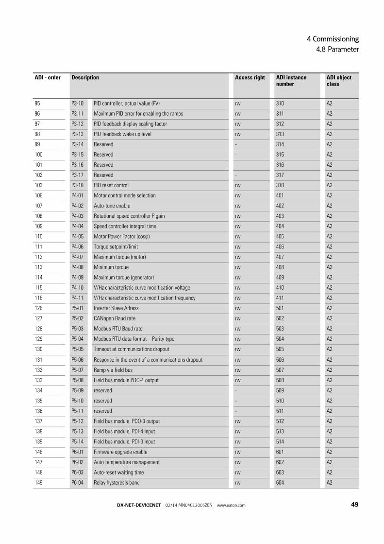
95 P3-10 PID controller, actual value (PV) rw 310 A2
96 P3-11 Maximum PID error for enabling the ramps rw 311 A2
97 P3-12 PID feedback display scaling factor rw 312 A2
98 P3-13 PID feedback wake up level rw 313 A2
99 P3-14 Reserved - 314 A2
100 P3-15 Reserved - 315 A2
101 P3-16 Reserved - 316 A2
102 P3-17 Reserved - 317 A2
103 P3-18 PID reset control rw 318 A2
106 P4-01 Motor control mode selection rw 401 A2
107 P4-02 Auto-tune enable rw 402 A2
108 P4-03 Rotational speed controller P gain rw 403 A2
109 P4-04 Speed controller integral time rw 404 A2
110 P4-05 Motor Power Factor (cosϕ) rw 405 A2
111 P4-06 Torque setpoint/limit rw 406 A2
112 P4-07 Maximum torque (motor) rw 407 A2
113 P4-08 Minimum torque rw 408 A2
114 P4-09 Maximum torque (generator) rw 409 A2
115 P4-10 V/Hz characteristic curve modification voltage rw 410 A2
116 P4-11 V/Hz characteristic curve modification frequency rw 411 A2
126 P5-01 Inverter Slave Adress rw 501 A2
127 P5-02 CANopen Baud rate rw 502 A2
128 P5-03 Modbus RTU Baud rate rw 503 A2
129 P5-04 Modbus RTU data format – Parity type rw 504 A2
130 P5-05 Timeout at communications dropout rw 505 A2
131 P5-06 Response in the event of a communications dropout rw 506 A2
132 P5-07 Ramp via field bus rw 507 A2
133 P5-08 Field bus module PDO-4 output rw 508 A2
134 P5-09 reserved - 509 A2
135 P5-10 reserved - 510 A2
136 P5-11 reserved - 511 A2
137 P5-12 Field bus module, PDO-3 output rw 512 A2
138 P5-13 Field bus module, PDI-4 input rw 513 A2
139 P5-14 Field bus module, PDI-3 input rw 514 A2
146 P6-01 Firmware upgrade enable rw 601 A2
147 P6-02 Auto temperature management rw 602 A2
148 P6-03 Auto-reset waiting time rw 603 A2
149 P6-04 Relay hysteresis band rw 604 A2
ADI - order Description Access right ADI instance number
ADI object class
DX-NET-DEVICENET 02/14 MN04012005ZEN www.eaton.com 49
4 Commissioning
4.8 Parameter
150 P6-05 Enable incremental encoder feedback rw 605 A2
151 P6-06 Incremental encoder scale rw 606 A2
152 P6-07 Maximum speed error rw 607 A2
153 P6-08 Input frequency at maximum speed rw 608 A2
154 P6-09 Droop speed rw 609 A2
155 P6-10 PLC function enable rw 610 A2
156 P6-11 Speed holding time in the event of an enable signal rw 611 A2
157 P6-12 Speed holding time in the event of a disable signal rw 612 A2
158 P6-13 Motor brake opening time rw 613 A2
159 P6-14 Motor brake engagement delay rw 614 A2
160 P6-15 Minimum torque for brake opening rw 615 A2
161 P6-16 Minimum torque time limit rw 616 A2
162 P6-17 Maximum torque time limit rw 617 A2
163 P6-18 Voltage for DC injection braking rw 618 A2
164 P6-19 Brake resistor value rw 619 A2
165 P6-20 Brake resistor power rw 620 A2
166 P6-21 Braking chopper cycle in the event of excessively low temperature
rw 621 A2
167 P6-22 Reset fan run-time rw 622 A2
168 P6-23 kWh meter reset rw 623 A2
169 P6-24 Service interval rw 624 A2
170 P6-25 Service interval reset rw 625 A2
171 P6-26 AO1, scaling rw 626 A2
172 P6-27 AO1, Offset rw 627 A2
173 P6-28 Display index P0-80 rw 628 A2
174 P6-29 Save parameters as default rw 629 A2
175 P6-30 Access code for menu level 3 rw 630 A2
176 P7-01 Motor stator resistance rw 701 A2
177 P7-02 Rotor resistance rw 702 A2
178 P7-03 Motor leakage inductance (d) rw 703 A2
179 P7-04 Motor magnetizing current rw 704 A2
180 P7-05 Motor leakage factor rw 705 A2
181 P7-06 Motor leakage inductance (q) rw 706 A2
182 P7-07 Advanced generator control rw 707 A2
183 P7-08 Enable, motor parameter adaptation rw 708 A2
184 P7-09 Overvoltage current limit rw 709 A2
185 P7-10 Load inertia factor rw 710 A2
186 P7-11 Minimum PWM pulse width rw 711 A2
ADI - order Description Access right ADI instance number
ADI object class
50 DX-NET-DEVICENET 02/14 MN04012005ZEN www.eaton.com

4 Commissioning
4.8 Parameter
187 P7-12 Magnetizing time at the U/f method rw 712 A2
188 P7-13 Rotational speed controller D gain rw 713 A2
189 P7-14 Torque boost rw 714 A2
190 P7-15 Maximum frequency limit for torque boost rw 715 A2
191 P7-16 Enable, signal injection rw 716 A2
192 P7-17 Signal injection level rw 717 A2
196 P8-01 Second acceleration time (acc2) rw 801 A2
197 P8-02 Transition frequency (acc1 - acc2) rw 802 A2
198 P8-03 Third acceleration time (acc3) rw 803 A2
199 P8-04 Transition frequency (acc2 - acc3) rw 804 A2
200 P8-05 Fourth acceleration time (acc4) rw 805 A2
201 P8-06 Transition frequency (acc3 - acc4) rw 806 A2
202 P8-07 Fourth deceleration time (dec4) rw 807 A2
203 P8-08 Transition frequency (dec3 - dec4) rw 808 A2
204 P8-09 Third deceleration time (dec3) rw 809 A2
205 P8-10 Transition frequency (dec2 - dec3) rw 810 A2
206 P8-11 Second deceleration time (dec2) rw 811 A2
207 P8-12 Transition frequency (dec1 - dec2) rw 812 A2
208 P8-13 Ramp selection when there is a preset speed rw 813 A2
216 P9-01 Control source - enable rw 901 A2
217 P9-02 Control source - quick stop rw 902 A2
218 P9-03 Control source - start signal 1 (FWD) rw 903 A2
219 P9-04 Control source – start signal 2 (REV) rw 904 A2
220 P9-05 Control source - Stay-put function rw 905 A2
221 P9-06 Control source - enable (REV) rw 906 A2
222 P9-07 Control source - reset rw 907 A2
223 P9-08 Control source – external fault rw 908 A2
224 P9-09 Control source - terminal control rw 909 A2
225 P9-10 Source - Speed 1 rw 910 A2
226 P9-11 Source - speed 2 rw 911 A2
227 P9-12 Source - speed 3 rw 912 A2
228 P9-13 Source - speed 4 rw 913 A2
229 P9-14 Source - speed 5 rw 914 A2
230 P9-15 Source - speed 6 rw 915 A2
231 P9-16 Source - speed 7 rw 916 A2
232 P9-17 Source - speed 8 rw 917 A2
233 P9-18 Speed - input 0 rw 918 A2
234 P9-19 Speed - input 1 rw 919 A2
ADI - order Description Access right ADI instance number
ADI object class
DX-NET-DEVICENET 02/14 MN04012005ZEN www.eaton.com 51
4 Commissioning
4.8 Parameter
235 P9-20 Speed - input 2 rw 920 A2
236 P9-21 Fixed frequency 0 rw 921 A2
237 P9-22 Fixed frequency 1 rw 922 A2
238 P9-23 Fixed frequency 2 rw 923 A2
239 P9-24 Acceleration ramp input 0 rw 924 A2
240 P9-25 Acceleration ramp input 1 rw 925 A2
241 P9-26 Deceleration time input 0 rw 926 A2
242 P9-27 Deceleration time input 1 rw 927 A2
243 P9-28 Control source - Up-pushbutton rw 928 A2
244 P9-29 Control source - Down-pushbutton rw 929 A2
245 P9-30 FWD limit switch rw 930 A2
246 P9-31 REV limit switch rw 931 A2
247 P9-32 reserved - 932 A2
248 P9-33 Source - analog output (AO) 1 rw 933 A2
249 P9-34 Source - analog output (AO) 2 rw 934 A2
250 P9-35 Control source - Relay 1 rw 935 A2
251 P9-36 Control source - Relay 2 rw 936 A2
252 P9-37 Control source - scaling rw 937 A2
253 P9-38 Source - PID setpoint value rw 938 A2
254 P9-39 Source - PID feedback rw 939 A2
255 P9-40 Source - torque control reference rw 940 A2
256 P9-41 Function choices - Relay output 3, 4, 5 rw 941 A2
266 DI 1 (Digital input 1) ro 1001 A2
267 DI 2 (Digital input 2) ro 1002 A2
268 DI 3 (Digital input 3) ro 1003 A2
269 DI 4 (Digital input 4 ro 1004 A2
270 DI 5 (Digital input 5) ro 1005 A2
271 DI 6 (Digital input 6) ro 1006 A2
272 DI 7 (Digital input 7) ro 1007 A2
273 DI 8 (Digital input 8) ro 1008 A2
274 AO 1 (analog output 1) ro 1009 A2
275 AO 2 (analog output 2) ro 1010 A2
276 DO 1 (Digital output 1) ro 1011 A2
277 DO 2 (Digital output 2) ro 1012 A2
278 DO 3 (Digital output 3) ro 1013 A2
279 DO 4 (Digital output 4) ro 1014 A2
280 DO 5 (Digital output 5) ro 1015 A2
282 User register 1 rw 1017 A2
ADI - order Description Access right ADI instance number
ADI object class
52 DX-NET-DEVICENET 02/14 MN04012005ZEN www.eaton.com

4 Commissioning
4.8 Parameter
283 User register 2 rw 1018 A2
284 User register 3 rw 1019 A2
285 User register 4 rw 1020 A2
286 User register 5 rw 1021 A2
287 User register 6 rw 1022 A2
288 User register 7 rw 1023 A2
289 User register 8 rw 1024 A2
290 User register 9 rw 1025 A2
291 User register 10 rw 1026 A2
292 User register 11 rw 1027 A2
293 User register 12 rw 1028 A2
294 User register 13 rw 1029 A2
295 User register 14 rw 1030 A2
296 User register 15 rw 1031 A2
297 User AO 1 (analog output 1) rw 1032 A2
298 User AO 2 (analog output 2) rw 1033 A2
301 User RO 1 (relay output 1) rw 1036 A2
302 User RO 2 (relay output 2) rw 1037 A2
303 User RO 3 (relay output 3) rw 1038 A2
304 User RO 4 (relay output 4) rw 1039 A2
305 User RO 5 (relay output 5) rw 1040 A2
306 User, scaling value rw 1041 A2
307 User, decimal scaling rw 1042 A2
308 User, speed reference rw 1043 A2
309 User, torque deference rw 1044 A2
310 Field bus / User ramp rw 1045 A2
311 Scope index 1 / 2 rw 1046 A2
312 Scope index 3 / 4 rw 1047 A2
313 24hour timer rw 1048 A2
314 User display Ctrl rw 1049 A2
315 User display value rw 1050 A2
326 AI 1 (analog input 1) (Q12) ro 1061 A2
327 AI 1 (analog input 1) (%) ro 1062 A2
328 AI 2 (analog input 2) (Q12) ro 1063 A2
329 AI 2 (analog input 2) (%) ro 1064 A2
330 DI (Digital input) Status ro 1065 A2
331 Speed reference ro 1066 A2
332 Value, digital potentiometer ro 1067 A2
ADI - order Description Access right ADI instance number
ADI object class
DX-NET-DEVICENET 02/14 MN04012005ZEN www.eaton.com 53
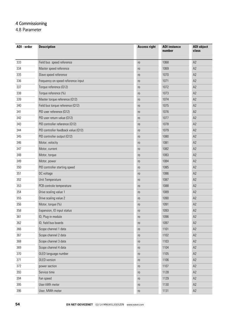
4 Commissioning
4.8 Parameter
333 Field bus speed reference ro 1068 A2
334 Master speed reference ro 1069 A2
335 Slave speed reference ro 1070 A2
336 Frequency on speed reference input ro 1071 A2
337 Torque reference (Q12) ro 1072 A2
338 Torque reference (%) ro 1073 A2
339 Master torque reference (Q12) ro 1074 A2
340 Field bus torque reference (Q12) ro 1075 A2
341 PID user reference (Q12) ro 1076 A2
342 PID user return value (Q12) ro 1077 A2
343 PID controller reference (Q12) ro 1078 A2
344 PID controller feedback value (Q12) ro 1079 A2
345 PID controller output (Q12) ro 1080 A2
346 Motor, velocity ro 1081 A2
347 Motor, current ro 1082 A2
348 Motor, torque ro 1083 A2
349 Motor, power ro 1084 A2
350 PID controller starting speed ro 1085 A2
351 DC voltage ro 1086 A2
352 Unit Temperature ro 1087 A2
353 PCB controle temperature ro 1088 A2
354 Drive scaling value 1 ro 1089 A2
355 Drive scaling value 2 ro 1090 A2
356 Motor, torque (%) ro 1091 A2
358 Expansion, IO input status ro 1093 A2
361 ID, Plug-in module ro 1096 A2
362 ID, field bus boards ro 1097 A2
366 Scope channel 1 data ro 1101 A2
367 Scope channel 2 data ro 1102 A2
368 Scope channel 3 data ro 1103 A2
369 Scope channel 4 data ro 1104 A2
370 OLED language number ro 1105 A2
371 OLED version ro 1106 A2
372 power section ro 1107 A2
393 Service time ro 1128 A2
394 Fan speed ro 1129 A2
395 User kWh meter ro 1130 A2
396 User, MWh meter ro 1131 A2
ADI - order Description Access right ADI instance number
ADI object class
54 DX-NET-DEVICENET 02/14 MN04012005ZEN www.eaton.com

4 Commissioning
4.8 Parameter
397 Complete, KWh meter ro 1132 A2
398 Complete, MWh meter ro 1133 A2
399 Total, operating hours meter ro 1134 A2
400 Total, operating minutes/seconds meter ro 1135 A2
401 User, hours-run meter ro 1136 A2
402 User, operating minutes/seconds meter ro 1137 A2
ADI - order Description Access right ADI instance number
ADI object class
DX-NET-DEVICENET 02/14 MN04012005ZEN www.eaton.com 55

4 Commissioning
4.8 Parameter
56 DX-NET-DEVICENET 02/14 MN04012005ZEN www.eaton.com

Index
AAbbreviations . . . . . . . . . . . . . . . . . . . . . . . . . . . . . . 5
Acknowledge Handler Object . . . . . . . . . . . . . . . 29
ADI (Application Data Instance) . . . . . . . . . . . . 5, 32
ADI Object . . . . . . . . . . . . . . . . . . . . . . . . . . . . . . . 29
Altitude . . . . . . . . . . . . . . . . . . . . . . . . . . . . . . . . . . . 9
Application Objects . . . . . . . . . . . . . . . . . . . . . . . . 29
Assembly Object . . . . . . . . . . . . . . . . . . . . . . . . . . 29
BBaud Rate . . . . . . . . . . . . . . . . . . . . . . . . . . . . . . 9, 22
CCable
Flat Cable . . . . . . . . . . . . . . . . . . . . . . . . . . . . . 22
Thick Cable . . . . . . . . . . . . . . . . . . . . . . . . . . . 22
Thin Cable . . . . . . . . . . . . . . . . . . . . . . . . . . . . 22
CIP . . . . . . . . . . . . . . . . . . . . . . . . . . . . . . . . . . . . . . 13
CIP (Control and Information Protocol) . . . . . . 5, 13
Climatic proofing . . . . . . . . . . . . . . . . . . . . . . . . . . . 9
Command . . . . . . . . . . . . . . . . . . . . . . . . . . . . . . . . 41
Communication protocol . . . . . . . . . . . . . . . . . . . . 9
Connection Object . . . . . . . . . . . . . . . . . . . . . 28, 33
Control cables . . . . . . . . . . . . . . . . . . . . . . . . . . . . 23
COS (Change of State) . . . . . . . . . . . . . . . . . . . 5, 29
CW (Control Word) . . . . . . . . . . . . . . . . . . . . . . . . . 5
DData Types . . . . . . . . . . . . . . . . . . . . . . . . . . . . . . . . 6
Degree of protection . . . . . . . . . . . . . . . . . . . . . . . . 9
Device status . . . . . . . . . . . . . . . . . . . . . . . . . . . . . 42
DeviceNet Object . . . . . . . . . . . . . . . . . . . . . . . . . 28
Displays . . . . . . . . . . . . . . . . . . . . . . . . . . . . . . . . . 43
DX-NET-DEVICENETDesignation . . . . . . . . . . . . . . . . . . . . . . . . . . . . 8
electrical connection . . . . . . . . . . . . . . . . . . . 15
mounting . . . . . . . . . . . . . . . . . . . . . . . 15, 17, 19
proper use . . . . . . . . . . . . . . . . . . . . . . . . . . . . 10
Replacing . . . . . . . . . . . . . . . . . . . . . . . . . . . . . 11
EEDS file . . . . . . . . . . . . . . . . . . . . . . . . . . . . . . . . . . 25
Engineering . . . . . . . . . . . . . . . . . . . . . . . . . . . . . . 26
Environmental Conditions . . . . . . . . . . . . . . . . . . . 9
Equipment supplied . . . . . . . . . . . . . . . . . . . . . . . . 7
Error Messages . . . . . . . . . . . . . . . . . . . . . . . . . . . 43
Explicit Messages . . . . . . . . . . . . . . . . . . . . . . . . . 33
Explicit Messaging . . . . . . . . . . . . . . . . . . . . . . . . 13
FFailure code . . . . . . . . . . . . . . . . . . . . . . . . . . . . . . 43
HHazard warnings . . . . . . . . . . . . . . . . . . . . . . . . . . . 4
Hotline . . . . . . . . . . . . . . . . . . . . . . . . . . . . . . . . . . . 11
IIdentity Object . . . . . . . . . . . . . . . . . . . . . . . . . 28, 30
Inspection . . . . . . . . . . . . . . . . . . . . . . . . . . . . . . . . 11
Installation . . . . . . . . . . . . . . . . . . . . . . . . . . . . . . . 15
Instructional leaflet . . . . . . . . . . . . . . . . . . . . . . . . . 7
IL4020010Z . . . . . . . . . . . . . . . . . . . . . . . . . . . 16
IL4020011Z . . . . . . . . . . . . . . . . . . . . . . . . . . . 16
Interference emissions . . . . . . . . . . . . . . . . . . . . . . 9
Interference immunity . . . . . . . . . . . . . . . . . . . . . . 9
KKey to part numbers . . . . . . . . . . . . . . . . . . . . . . . . 8
LLED (Light Emitting Diode) . . . . . . . . . . . . . . . . . . 5
Module status (MS) . . . . . . . . . . . . . . . . . . . . . 8
Network status (NS) . . . . . . . . . . . . . . . . . . . . 8
LSB (Least Significant Bit) . . . . . . . . . . . . . . . . 5, 42
MMAC address . . . . . . . . . . . . . . . . . . . . . . . . . . . . . 25
MAC ID (Media Access Control Identifier) . . 5, 25
Mains supply voltages . . . . . . . . . . . . . . . . . . . . . . 6
Maintenance . . . . . . . . . . . . . . . . . . . . . . . . . . . . . 11
Maintenance interval . . . . . . . . . . . . . . . . . . . . . . 11
ManualMN04020005Z . . . . . . . . . . . . . . . . . . . . . . . . 25
Maximum cable length . . . . . . . . . . . . . . . . . . . . . 22
Message Router Object . . . . . . . . . . . . . . . . . . . . 28
Motor cables . . . . . . . . . . . . . . . . . . . . . . . . . . . . . 23
MSB (Most Significant Bit) . . . . . . . . . . . . . . . . 5, 42
NNetwork address . . . . . . . . . . . . . . . . . . . . . . . . . . 25
Notes, on the documentation . . . . . . . . . . . . . . . 16
DX-NET-DEVICENET 02/14 MN04012005ZEN www.eaton.com 1

OObject model . . . . . . . . . . . . . . . . . . . . . . . . . . . . . 28
ObjectsApplication-specific . . . . . . . . . . . . . . . . . . . . 28
Connection objects . . . . . . . . . . . . . . . . . . . . 28
Management objects . . . . . . . . . . . . . . . . . . . 28
ODVA (Open DeviceNet Vendor Association) . 3, 5
Operation temperature . . . . . . . . . . . . . . . . . . . . . . 9
PParameter Data . . . . . . . . . . . . . . . . . . . . . . . . . . . 47
Parameter Object . . . . . . . . . . . . . . . . . . . . . . . . . 29
Parametersacyclic . . . . . . . . . . . . . . . . . . . . . . . . . . . . . . . 46
Part no. . . . . . . . . . . . . . . . . . . . . . . . . . . . . . . . . . . . 8
PD (Process Data) . . . . . . . . . . . . . . . . . . . . . . . . . . 5
PDI (Process Data Interface) . . . . . . . . . . . 5, 41, 42
Pin assignment . . . . . . . . . . . . . . . . . . . . . . . . . . . 21
PLC (Programmable logic controller) . . . . . . . 5, 13
PNU = (parameter number) . . . . . . . . . . . . 5, 41, 46
Production quality . . . . . . . . . . . . . . . . . . . . . . . . . . 9
RRated operational data . . . . . . . . . . . . . . . . . . . . . . 9
SSetpoint value . . . . . . . . . . . . . . . . . . . . . . . . . . . . 42
Signal cables . . . . . . . . . . . . . . . . . . . . . . . . . . . . . 23
Standards . . . . . . . . . . . . . . . . . . . . . . . . . . . . . . . . . 9
Statusword . . . . . . . . . . . . . . . . . . . . . . . . . . . . . . . 42
Storage temperature . . . . . . . . . . . . . . . . . . . . . 9, 11
SW (Status Word), see Status Word . . . . . . . . . . 5
UUL (underwriters laboratories) . . . . . . . . . . . . . . . . 5
Units of measurement . . . . . . . . . . . . . . . . . . . . . . 6
VVibration . . . . . . . . . . . . . . . . . . . . . . . . . . . . . . . . . . 9
WWarranty . . . . . . . . . . . . . . . . . . . . . . . . . . . . . . . . . 11
Writing conventions . . . . . . . . . . . . . . . . . . . . . . . . 4
2 DX-NET-DEVICENET 02/14 MN04012005ZEN www.eaton.com