dwyer series 160 stainless steel pitot tubes · pdf fileseries 160 stainless steel pitot tubes...
TRANSCRIPT
Series 160 Stainless Steel Pitot Tubes
Specifications - Installation and Operating Instructions
Bulletin H-11
DWYER INSTRUMENTS, INC. Phone: 219/879-8000 www.dwyer-inst.comP.O. BOX 373 • MICHIGAN CITY, INDIANA 46361, U.S.A. Fax: 219/872-9057 e-mail: [email protected]
The total pressure of an air stream flowing in a duct is the sum ofthe static or bursting pressure exerted upon the sidewalls of theduct and the impact or velocity pressure of the moving air. Throughthe use of a pitot tube connected differentially to a manometer, thevelocity pressure alone is indicated and the corresponding airvelocity determined.
For accuracy of plus or minus 2%, as in laboratory applications,extreme care is required and the following precautions should beobserved:
1. Duct diameter to be 30 times pitot tube diameter, orgreater.
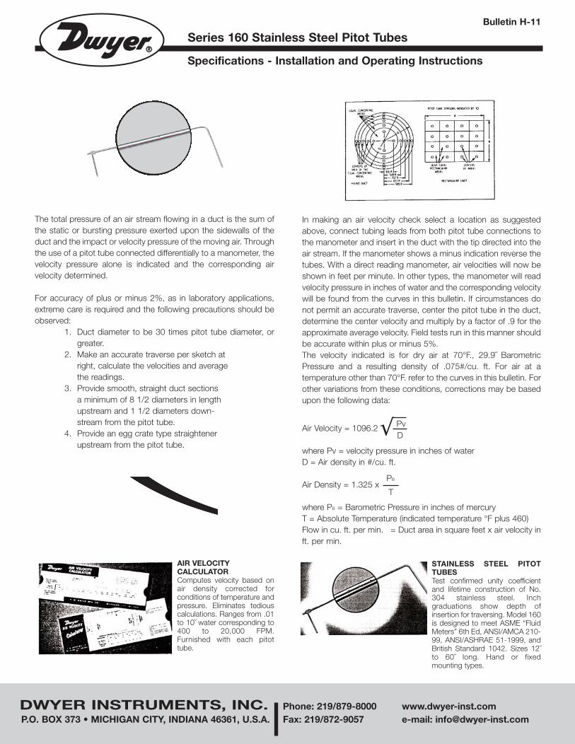
2. Make an accurate traverse per sketch atright, calculate the velocities and averagethe readings.
3. Provide smooth, straight duct sectionsa minimum of 8 1/2 diameters in lengthupstream and 1 1/2 diameters down-stream from the pitot tube.
4. Provide an egg crate type straightenerupstream from the pitot tube.
Air Velocity = 1096.2
where Pv = velocity pressure in inches of waterD = Air density in #/cu. ft.
Air Density = 1.325 x
where PB = Barometric Pressure in inches of mercuryT = Absolute Temperature (indicated temperature °F plus 460)Flow in cu. ft. per min. = Duct area in square feet x air velocity inft. per min.
√ PvD
PB
T
AIR VELOCITYCALCULATORComputes velocity based onair density corrected forconditions of temperature andpressure. Eliminates tediouscalculations. Ranges from .01to 10˝ water corresponding to400 to 20,000 FPM.Furnished with each pitottube.
STAINLESS STEEL PITOTTUBESTest confirmed unity coefficientand lifetime construction of No.304 stainless steel. Inchgraduations show depth ofinsertion for traversing. Model 160is designed to meet ASME “FluidMeters” 6th Ed, ANSI/AMCA 210-99, ANSI/ASHRAE 51-1999, andBritish Standard 1042. Sizes 12˝to 60˝ long. Hand or fixedmounting types.
In making an air velocity check select a location as suggestedabove, connect tubing leads from both pitot tube connections tothe manometer and insert in the duct with the tip directed into theair stream. If the manometer shows a minus indication reverse thetubes. With a direct reading manometer, air velocities will now beshown in feet per minute. In other types, the manometer will readvelocity pressure in inches of water and the corresponding velocitywill be found from the curves in this bulletin. If circumstances donot permit an accurate traverse, center the pitot tube in the duct,determine the center velocity and multiply by a factor of .9 for theapproximate average velocity. Field tests run in this manner shouldbe accurate within plus or minus 5%.The velocity indicated is for dry air at 70°F., 29.9˝ BarometricPressure and a resulting density of .075#/cu. ft. For air at atemperature other than 70°F. refer to the curves in this bulletin. Forother variations from these conditions, corrections may be basedupon the following data:
H-11 8/30/05 3:33 PM Page 1

DWYER INSTRUMENTS, INC. Phone: 219/879-8000 www.dwyer-inst.comP.O. BOX 373 • MICHIGAN CITY, INDIANA 46361, U.S.A. Fax: 219/872-9057 e-mail: [email protected]
©Copyright 2005 Dwyer Instruments, Inc. Printed in U.S.A. 8/05 FR# 440226-00 Rev. 8
AIR
VE
LOC
ITY
IN
FE
ET
PE
R M
INU
TE
GAGE READING WITH PITOT TUBE (VELOCITY PRESSURE) IN INCHES OF WATER
GAGE READING WITH PITOT TUBE (VELOCITY PRESSURE) IN INCHES OF WATER
AIR
VE
LOC
ITY
IN
FE
ET
PE
R M
INU
TE
H-11 8/30/05 3:33 PM Page 2