dwherr01/xin/activities and findings.docx · web viewfigure 2 compares the normal incidence...
TRANSCRIPT

Activities and Findings for NSF SBIR
Title: Realizing Broadband Frequency Sound Absorption in Micro-Slit PanelsCompany: Ward Process dba American Acoustical ProductsAward Number: 1113541
Part 1: Project Overview and Objectives1.1 Overview
The NSF SBIR grant funded the research efforts of American Acoustical Products (AAP) to develop improved micro-perforated panel (MPP) sound absorbers. For ordinary perforated panels, pore diameters are on the order of millimeters or even centimeters with little acoustic resistance. MPP absorbers have pore diameters sub-millimeter in size. Due to the small holes, MPP absorbers provide acoustic resistance, which enhances the sound attenuation. Unlike traditional sound absorbing materials like foam and fiber, MPP absorbers are unique because they are sustainable and reclaimable, non-combustible, rugged, fiber free, light weight, and aesthetically pleasing. It is anticipated that the absorbers will be especially advantageous for use in heating, ventilation, and air conditioning systems in schools, cruise ships, hospitals, clinics, and food processing facilities.
However, there are two primary obstacles to the widespread acceptance of MPP absorbers. First, many believe that MPP absorbers are too costly for commercial use. This was certainly the case in the past, when holes were circular in shape and were cut using a laser. However, American Acoustical Products (AAP) produces lower cost but similar micro-slit panel (MSP) absorbers. Slits are non-circular and are cut or pressed into metal or plastic. It has been shown that micro-slit absorbers have a slightly smaller acoustic resistance, but function like MPP absorbers for all practical purposes [1-2]. Figure 1 shows photographs of a traditional MPP and MSP absorber under light.
Figure 1 Photographs of MPP and MSP under light
It should be noted that commonly used absorbers such as fiber or foam are priced based on the varying thickness of material. Thicker materials are needed for lower frequencies. Once thicknesses exceed 6 inches, the price of a MSP absorber is comparable once longevity and installation costs are included. AAP typically sells Millennium Metal (AAP’s MSP absorber) based on performance. The current product is
1

2 to 3 times more expensive than fiberglass, but outperforms fiber at low frequencies. Indeed, sales have been especially strong for Millennium Metal in the transportation industry.
The second and perhaps more important obstacle is that MPP absorbers are tuned and not broadband absorbers. Figure 2 compares the normal incidence acoustic absorption coefficient of a MSP absorber with a backing cavity depth of 70 mm to typical foam occupying the same volume. Notice that the MSP absorber performs as well as foam in certain frequency bands and is more effective at lower frequencies than foam. This is particularly advantageous because many noise sources (engines, pumps) are dominated by low frequency content. However, the comparison also illustrates that the MSP absorber is ineffective in certain frequency bands and does not perform well as a broadband frequency absorber.
An MSP absorber is best thought of as a combination of the panel plus a backing cavity. Indeed, the geometric parameter that is most instrumental in tuning the performance of an MSP is the depth of the backing cavity. The backing cavity depth controls the particle velocity. MSP absorbers are most effective when the particle velocity in the pores is high because this maximizes the viscous friction in the holes. This will be the case when the backing cavity depth is approximately a quarter acoustic wavelength.
Figure 2 Comparison of absorption coefficient between typical foam and MSP.
The objective of the funded research was to develop MSP absorbers that will perform comparably to foams and fibers while retaining their inherent advantages. It was proposed that performance could be improved by:
Spatially varying the porosity and slit size across the panel. Designing backing substrates, which vary the cavity depth without increasing the
occupied volume.
Accordingly, the focus of the funded work was to examine each of these possibilities.
1.2 Technical Objectives
The specific objectives of the funded work for Phase 1 were as follows. The AAP Team conducted product development research to:
0
0.2
0.4
0.6
0.8
1
0 1000 2000 3000 4000 5000
Frequency (Hz)
Abs
orpt
ion
Coe
ffici
net Foam
MSP
2

1. Determine the transfer impedance of different slit size and porosity combinations using simulation and measurement.
2. Develop and evaluate concepts for the backing substrate that effectively increase and vary the depth of the cavity posterior to the MSP absorber.
3. Design and fabricate several small panel specimens with substrates and measure the absorption using ASTM E1050.
4. Use boundary element method (BEM) simulation to determine how slit size, porosity, and cavity depth should be varied across a panel in order to achieve improved acoustical performance.
5. Design and fabricate three prospective panels and measure their performance in a heating, ventilation, and air conditioning (HVAC) plenum chamber. Additionally, assess MSP absorber performance using random incident absorption measurements (similar to ASTM C423).
Part 2: Research Activities2.1 Determination of the Transfer Impedance for Different Slit Geometries
The first objective was to gain a better understanding for the range of performance that can be achieved by varying the porosity and slit size of the MSP absorber. Accordingly, the transfer impedance of several samples with varying slit size was measured. The transfer impedance concept is illustrated in Figure 3. Transfer impedance is defined as
(1)
where p1 is the upstream sound pressure and p2 is the downstream sound pressure. Particle velocity is continuous on both sides of the sample (i.e. v1 equals v2).
Figure 3 Schematic showing the approach for measuring transfer impedance.
The method utilized for measuring the transfer or series impedance [3] of a sample is shown in Figure 4. The impedance at the surface of the sample was measured twice using the two-microphone approach according to ASTM E1050 [4], once with the sample (Z1) and the second without (Z2). The transfer impedance is the difference between the two measurements.
3

Figure 4 Schematic showing the approach for measuring transfer impedance.
24 samples were measured from 6 different panels. Each panel had a different porosity that had been estimated by placing the panel in between a luminance meter and a light pad, and measuring the light intensity through the panel. A rough estimate of the porosity can be calculated as the ratio of the light intensities with and without a panel. The manufacturing process is not tightly controlled so the porosity will vary across the panel. Consequently, an estimate of the variation within panels was determined by measuring 4 samples from each panel.
For MSP absorbers, both porosity and slit dimensions are difficult to measure using traditional means. Slit dimensions vary with thickness, and the slit is angled through the metal. However, effective dimensions for the slit can be obtained by curve fitting the data to Maa’s equation [5-7]. Porosity and hole diameter were assumed in Maa’s equation and the predicted transfer impedance was compared to that measured in a least square sense. The transfer impedance of different combinations of porosity and hole diameter were calculated until optimum values were determined. This method has been documented in Reference 8.
The resulting work provided a database for relating slit dimensions to effective hole diameters and porosities. This provided a tool, which could then be utilized to develop MSP absorbers having optimized slit dimensions.
Figure 5 plots the effective porosity and hole diameter for each of the 24 samples. Samples from the same panel are identified as being the same color and shape. The effective hole diameter is fairly consistent and varies between 0.2 and 0.3 mm. Variations of this level will not greatly affect the absorption if the porosity is held constant. On the other hand, the effective porosity of the panel varies from between 2 and 8 percent.
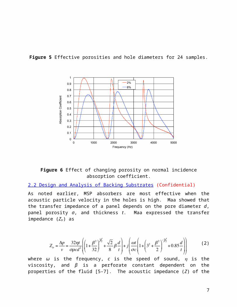
Figure 6 shows the absorption for panels with effective porosities of 2 and 8 percent with a 4 inch backing cavity depth. Though increasing the porosity widens the absorption bands at higher frequencies, the performance is degraded at lower frequencies which are often most important. Furthermore, the absorption is low at certain frequencies regardless of the porosity selected. The results demonstrated that
Z1
Sample
Loudspeaker
Microphones
Z2
Z1
Sample
Loudspeaker
Microphones
Z2
4

varying the porosity of a panel alone would not produce excellent broadband absorptive characteristics.
Figure 5 Effective porosities and hole diameters for 24 samples.
Figure 6 Effect of changing porosity on normal incidence absorption coefficient.
2.2 Design and Analysis of Backing Substrates (Confidential)
As noted earlier, MSP absorbers are most effective when the acoustic particle velocity in the holes is high. Maa showed that the transfer impedance of a panel depends on the pore diameter d, panel porosity σ, and thickness t. Maa expressed the transfer impedance (Ztr) as
5

(2)
where ω is the frequency, c is the speed of sound, is the viscosity, and β is a perforate constant dependent on the properties of the fluid [5-7]. The acoustic impedance (Z) of the sample is the summation of the transfer impedance plus the impedance of the backing cavity Zcav. Assuming an empty air-filled straight cavity, the impedance (Z) can be expressed as
(3)
where D is the depth of the backing cavity.
One way to improve the performance of MSP absorbers is to creatively vary the depth of the backing cavity. Jiang et al. [9] suggested using a triangular prism backed cavity and Sum [10] recommended a parallel stepped configuration. AAP has considered the options shown in Figure 7. The first option (Figure 7a) is a three-channel configuration where 3 different cavity depths are achieved. In the second case, a single straight channel is combined with an open cone. The open cone configuration had been suggested and patented by Wirt [11-12] over 30 years ago and termed a schizophonium. The schizophonium serves to increase the cavity depth while also adding a sudden area expansion (see Figure 7b).
Figure 7 Backing cavity configurations considered. a.) three channel. b) schizophonium with single straight channel.
Both cases in Figure 7 can be analyzed in a simple manner using plane wave theory. Each channel will have an impedance (Zi) which can be determined using Equation 3. Figure 8 is a schematic, which summarizes the modeling approach. In practice, the channels need not be straight, and can be wrapped around other channels as shown in Figure 7. Assuming plane waves, the sound pressure will be equal along the entire face of the perforate. In that case, the impedances, for each perforate and cavity, are in parallel with each other. The equivalent impedance (Zeq) can be determined by
6
(4)
Figure 8 Schematic illustrating the analysis approach.
The impedance of a schizophonium (ZSchiz) shown in Figure 7b can be predicted using plane wave theory. The cavity can be considered as two cones connected to one another by a sudden area expansion assuming that the distance c (in Figure 7b) is small. Several different variations are feasible and have not been patented. Channels can be rectangular or round in cross-section. However, the analysis process will be identical since the impedance depends on the cross-sectional area alone and not the geometric shape of the cross-section.
2.3 Design Samples and Measure Impedance and Absorption (Confidential)
A number of different samples were fabricated for testing in an impedance tube. The impedance and absorption for the different sample and substrate combinations were then measured using ASTM E1050 [4]. Results are not reported above 2000 Hz since the impedance tube is 100 mm in diameter (measurements are only valid up to 1800 Hz). Note that designing samples to fit inside a smaller diameter impedance tube is not practicable.
Figure 9 compares the measured sound absorption for a three-channel backing substrate to the case with no substrate at all. Simulation results are also included for comparison. Notice that introducing channels of varying depth improves the broadband attenuation significantly. The low frequency absorption is improved such that the absorption is above 0.5 just above 200 Hz and also between 1000 and 1800 Hz.
Figure 10 shows a similar case in which the middle channel is shortened. Though this case is more difficult to simulate due to the open flange connected to the middle channel, the measurement results were particularly promising. Again, notice the marked improvement at low frequencies and also in between 1000 and 1800 Hz. Recall that the impedance tube measurement was only valid up to 1800 Hz so the drop in absorption at high frequencies should be ignored.
Figure 11 compares the measured absorption for a MSP with a schizophonium used as a backing substrate to an MSP with an empty cavity. If schizophonium and empty cavity backings are alternated (as is suggested in Figure 7b), a suitable broadband absorber is likely to be obtained.
7

Figure 9 Comparison of measured and simulated results for the three-channel configuration shown at the right. Empty cavity results are also included for reference.
Figure 10 Comparison of measured and simulated results for an alternative three-channel configuration shown at the right. Measurement is valid up to 1800 Hz.
Figure 11 Absorption for a MSP with schizophonium backing substrate compared to that with an empty cavity. Measurement is valid up to 1800 Hz.
8

2.4 Boundary Element Method Simulation of Panels
In prior work, the University of Kentucky had used the boundary element method (BEM) to successfully predict the insertion loss produced by placing MSP absorbers into an enclosure [13]. In that study, the effect of adding partitioning behind an MSP absorber was investigated. The study confirmed earlier findings [14-15], which showed that partitioning the backing cavity improved the performance of the MSP. More importantly, the model provided a rationale for the improvement in performance. It was shown that acoustic waves that propagated normal to the panel were attenuated equally well with or without a partitioned substrate. However, the insertion loss associated with grazing waves (propagating parallel to the MSP absorber) was increased up to 8 dB with partitioning.
2.4.1 Effect of Partition Spacing
As part of this research effort, a follow-on effort was performed to determine what the spacing in between partitions should be. The setup for the study is shown in Figure 12 where the total length of the treated portion of the duct is 0.305 m. A duct was modeled with a velocity source on the left hand side and an anechoic termination on the right. A MSP with partitioned backing cavity was modeled. Several different spacings were considered. In each case, it was found that the partition spacing should be at a minimum less than a half acoustic wavelength in order for the material to behave in a locally reacting fashion. The sound pressure contour plot, which is inset in Figure 12, indicates half wavelength behavior in between the partitions. It should be noted that there appeared to be some advantage to varying the partition spacing across the treated portion of the duct. This effect will be considered during the next several months leading up to the Phase 2 submission.
Figure 12 A duct with MSP and partitioned backing cavity.
2.4.2 Effect of Varying the Slit Geometry Across a Panel
The effect of varying the slit geometry across a panel by changing the porosity was also examined using BEM analysis. In this case, it was assumed that the backing cavity was 2 inches in depth and was partitioned so that a locally reacting impedance model could be assumed. Using the current production techniques, Millennium Metal is limited to effective porosities between 2 and 8 percent so these two extremes were chosen. The effective pore diameter was selected to be 0.2 mm according to the results in Section
9

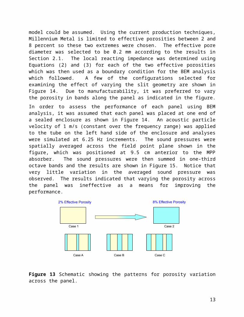
2.1. The local reacting impedance was determined using Equations (2) and (3) for each of the two effective porosities which was then used as a boundary condition for the BEM analysis which followed. A few of the configurations selected for examining the effect of varying the slit geometry are shown in Figure 14. Due to manufacturability, it was preferred to vary the porosity in bands along the panel as indicated in the figure.
In order to assess the performance of each panel using BEM analysis, it was assumed that each panel was placed at one end of a sealed enclosure as shown in Figure 14. An acoustic particle velocity of 1 m/s (constant over the frequency range) was applied to the tube on the left hand side of the enclosure and analyses were simulated at 6.25 Hz increments. The sound pressures were spatially averaged across the field point plane shown in the figure, which was positioned at 9.5 cm anterior to the MPP absorber. The sound pressures were then summed in one-third octave bands and the results are shown in Figure 15. Notice that very little variation in the averaged sound pressure was observed. The results indicated that varying the porosity across the panel was ineffective as a means for improving the performance.
Figure 13 Schematic showing the patterns for porosity variation across the panel.
Figure 14 Boundary element model used to assess the performance of the panel configurations shown in Figure 13. Boundary conditions are indicated.
10

Figure 15 BEM results showing comparison of spatially averaged sound pressure level on the field point plane indicated in Figure 14.
2.5 Fabricate and Measure Absorption of Panels (Confidential)
A small reverberation chamber (similar to an alpha cabin but much larger) [16] was used to measure the absorption of different panel constructions. The test procedure was to clamp the MSP absorber to the top of a frame utilizing 1-inch wide steel strips held in place by rare earth magnets. The cavity could then be filled with the backing substrate as required and the absorption coefficients of 4-inch deep systems were measured and compared. The absorption coefficient was measured in a manner similar to ASTM C423 [17] (except in a smaller room). Note that the absorption typically exceeds 1.0 for sound absorption measured in this manner. Earlier results shown in the report were impedance tube measurements (according to ASTM E1050) for which 1.0 is the maximum possible absorption. However, ASTM C423 is customarily used when comparing absorption results in a diffuse field and is a suitable performance metric for comparing absorption performance.
Four different backing substrates were considered and can be classified as:
Empty cavity Three-channel configuration Schizophonium (Arrangement 1) Schizophonium (Arrangement 2)
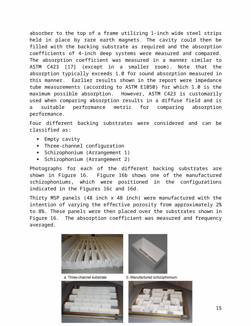
Photographs for each of the different backing substrates are shown in Figure 16. Figure 16b shows one of the manufactured schizophoniums, which were positioned in the configurations indicated in the Figures 16c and 16d.
Thirty MSP panels (48 inch x 48 inch) were manufactured with the intention of varying the effective porosity from approximately 2% to 8%. These panels were then placed over the substrates shown in Figure 16. The absorption coefficient was measured and frequency averaged.
11

Figure 16 Different backing cavity configurations considered.
The frequency-averaged absorption is plotted verses effective porosity in Figure 17. First of all, it was observed that the average absorption was much higher for cases where a backing substrate was utilized. It was also notable that the location of the maximum value for frequency-averaged absorption varied depending on the backing substrate used. Accordingly, it is best if the effective porosity of the MSP is optimized for a particular backing substrate.
Figure 17 Frequency-averaged sound absorption coefficients for MSP absorbers with different backing substrates.
12
Sound absorption (measured in a manner similar to ASTM-C423) in one-third octave bands is shown for the four different backing cavity configurations in Figure 18. In each case, an MSP was chosen with an effective porosity that would maximize the frequency-averaged absorption (according to Figure 17).
The results clearly demonstrate that the combined MSP and backing substrate substantially improves the sound absorbing characteristics over the entire frequency range when compared to an MSP without backing. Most importantly, the sound absorption is clearly improved at nearly all frequencies.
It should be noted that lower frequency absorption could be achieved by further increasing the backing cavity depth. Though increasing the cavity depth would increase the amount of volume occupied by the absorber, it would only marginally increase the cost.
Figure 18 Sound absorption (in one-third octave bands) for MSP absorbers with different backing substrates.
Part 3: Problems Encountered and Remaining (Unfulfilled Objectives)In general, each of the five stated research objectives/tasks was achieved (See Section 1.2). Every effort had been made so that the stated tasks in the SBIR Phase I proposal were achievable. Additionally, the AAP team was experienced using each of the measurement approaches detailed in the Activities and Findings (Part 2). There were delays in getting the MSP samples manufactured.
The only unfulfilled task was the objective to measure the panels in an actual HVAC plenum or system. AAP is currently communicating with two companies in an effort to set up tests to assess the performance of the designed panels and substrates in an
13

actual configuration. Furthermore, work is ongoing with an aim towards developing optimal panels.
Part 4: Summary and RecommendationsThe objective of this research was to develop MSP panel absorbers that would perform similarly to foams and fibers. The major findings of the funded research are as follows.
The effective porosity of the MSP absorbers manufactured by AAP can be varied between approximately 2 and 8 percent. However, the effective diameter of the panels stays relatively constant.
Varying the effective porosity impacts the sound absorption and should be optimized per the backing substrate. However, varying the effective porosity across the panel will be insufficient in and of itself to produce a broadband sound absorber.
Broadband absorption is best achieved by creatively changing the depth of the backing cavities by carefully designing a backing substrate. The AAP team developed two suitable configurations (three-channel and schizophonium) that provided broadband absorption above 500 Hz that was a significant improvement over that for an MSP with an empty cavity.
Based on these findings, the directions for a follow-on SBIR Phase II are as follows.
Though MSP and backing substrates have been developed that provide broadband absorption, the final design for the backing substrate will need to be optimized based on both performance and cost. For the Phase I research, functionality was emphasized over cost. The Phase II proposal will place a greater emphasis on reducing cost.
The MSP absorbers and backing substrates can likely be utilized most effectively if they are integrated into the system design. AAP aims to develop a suitable demonstration for an HVAC system that will validate the advantages of using the MSP absorbers.
Bibliography/References1. D. Y. Maa, “Theory of Microslit Absorbers”, Acta Acustica, 25, 481-485, 2000.
2. S. Allam, Y. Guo, M. Abom, “Acoustical Study of Micro- Perforated Plates for Vehicle Applications”, SAE Noise and Vibration Conference and Exhibition, St. Charles, IL, (2009).
3. T. W. Wu, C. Y. R. Cheng, Z. Tao, “Boundary Element Analysis of Packed Silencers with Protective Cloth and Embedded Thin Surfaces,” Journal of Sound and Vibration, 261, 1-15 (2003).
4. ASTM, “Standard Test Method for Impedance and Absorption of Acoustical Materials Using a Tube, Two Microphones, and a Digital Frequency Analysis System”, ASTM E1050-98, American Society of Testing and Materials, Philadelphia, 1998.
5. D. Y. Maa, “Theory and Design of Microperforated-Panel Sound-Absorbing Construction”, Sci. Sin. XVIII 55-71 (1975).
6. D. Y. Maa, “Microperforated-Panel Wideband Absorbers”, Noise Control Eng. J. 29, 77-84 (1997).
7. D. Y. Maa, “Potential of Microperforated Absorber”, J. Acoust. Soc. Am. 104, 2861–2866 (1998).
14
8. J. Liu and Herrin, D. W., “Effect of Contamination on Acoustic Performance of Microperforated Panels,” SAE International Journal of Passenger Cars – Mechanical Systems, Vol. 4, No. 2, pp. 1156-1161 (2011).
9. W. Jiang, X. Liu, and C. Wang, “Some Numeric and Experimental Study [sic] of Microperforated Panel Acoustic Absorbers with Heterogeneous Cavities”, 13th International Congress on Sound and Vibration, Vienna, Austria (2006).
10. K. S. Sum, “Use of Parallel Microperforated panel subabsorbers for Noise Control in Ducts,” 13th International Congress on Sound and Vibration, Vienna, Austria (2006).
11. L. S. Wirt, “Sound-Absorptive Materials to Meet Special Requirements,” Journal of the Acoustical Society of America, Vol. 57, No. 1, pp. 126-143 (1975).
12. L. S. Wirt, “Dual-Range Sound Absorber,” US Patent No. 3,887,031, June 3, 1975.
13. J. Liu, D. W. Herrin, “Enhancing Microperforated Panel Attenuation by Partitioning the Adjoining Cavity,” Applied Acoustics, 71, 120-127 (2010).
14. M. Yairi, K. Sakagami, M. Morimoto, A. Minemura, “Acoustical Properties of Microperforated Panel Absorbers with Various Configurations of the Back Cavity”, 12th International Congress on Sound and Vibration, Lisbon, Portugal (2005).
15. M. Toyoda, D. Takahashi, “Sound Transmission through a Microperforated Panel Structure with Subdivided Air Cavities”, J. Acoust. Soc. Am. 124, 3594-3603 (2008).
16. P. Jackson, “Design and Construction of a Small Reverberation Chamber,” SAE Noise and Vibration Conference, Traverse City, MI, Paper No. 2003-01-1679 (2003).
17. ASTM C423-09a, Standard Test Method for Sound Absorption and Sound Absorption Coefficients by the Reverberation Room Method, American Society for Testing and Materials (2009).
15