dwa, otn, and network administration - · pdf filefrom ocean to cloud dwa, otn, and network...
TRANSCRIPT
from ocean to cloud
DWA, OTN, and Network Administration
Presenters: Shelby Jackson & Gavin Doyle
Company: AT&T & Vodafone

from ocean to cloud
Presenter Profile
Shelby Jackson has a Bachelor of Science degree in Decision Sciences from the University of Denver, Colorado. Shelby joined AT&T in 1993 doing financial/accounting support for Network Services. In 1999, Shelby moved to Undersea Cable Operations and Management. Since then, Shelby has led the AT&T Network Administration (NA) team. Under Shelby’s direction, AT&T is the NA for several consortia undersea cable systems (Americas-1/Columbus-2, Americas-II, Columbus-III, China-US, Japan-US, and Taino-Carib). Shelby’s team also supports NA activities for multiple additional cables landing in AT&T-owned stations. For the past 5 years, Shelby has been using his NA and analytical expertise to support/help lead upgrades of several undersea cables, including network design models, contract evaluation, supplier selection, and detailed cost management and allocation.
• Name: Shelby Jackson
• Title: Manager, AT&T Network Administration
• Email: [email protected]
from ocean to cloud
Presenter Profile
Gavin is a Senior Engineer - Submarine Systems Engineering - at Vodafone and is predominately involved in upgrade projects providing technical and commercial specification, contract negotiation, tender evaluation, project management and quality assurance services to external customers. In addition to this, Gavin is also involved in the management of Vodafone’s dedicated submarine cable investments.
Gavin has a degree in Electronics and Communications Engineering and has been involved in engineering since the start of his career as an apprentice for Cosworth Racing working in the field of F1, WRC and Indycar race engine electronics.
• Name: Gavin Doyle
• Title: Senior Engineer, Vodafone Submarine Systems Engineering
• Email: [email protected]

from ocean to cloud
Master-class overview
This master-class will briefly describe the current SLTE/ADM technologies (interfaces and management/control systems) that are available and how these technologies affect network administration. It is then intended to go into detail on some examples of how a cable system can be configured using these technologies. It is also intended to discuss the efficiency of submarine cables systems.
The technologies explained will be as follows:
• Direct Wave Access (to clarify what this actually is)
• OTN interfaces (ITU-T G.709)
• LAN/WAN Phy Ethernet interfaces
• Pass-through SLTEs
• SLTE cross-connects
• ASON/GMPLS

from ocean to cloud
Direct Wavelength Access (DWA) vs ADM/MUX/Router configuration: ADM/MUX/Router
configuration DWA configuration

from ocean to cloud
Direct Wavelength Access (DWA):
• Direct access to the SLTE client signal (via ODF)
• Predominantly 10G, some 2.5G
• Unprotected wet bandwidth

from ocean to cloud
Direct Wavelength Access (DWA): Purpose
• Communication: IP, Mesh-network elements need to “talk to each other”
• Control: Reroute to secondary links with similar characteristics (e.g. latency), often on different cables
• Optimization: “Pick and choose” which capacity to recover in a given link
• DWA adopted to facilitate implementation of larger bandwidth IP, Mesh networks on undersea cables
from ocean to cloud
Direct Wavelength Access (DWA): Result
• Migrate the SDH/MUX/Router layer from the Submarine Cable system to the customer network.
• Cable becomes a ‘dumb pipe’.
• Cable network management only has to monitor SLTE alarms and point-to-point link performance (Regenerator Section).
• Cable system can accommodate various different types of client interface instead of the interfaces demanded by the ADM/Mux/Router.

from ocean to cloud
Direct Wavelength Access (DWA): Current Environment
• Varies based on specific cable technology
• Increased demand for Ethernet at client interface (vs. SDH/SONET)
• Client interface type software selectable
• Transceiver selection: 1310 (intra office) vs. 1550 (inter-office)
SLTE
D W D M
2.5G
10G
40G
100G
2.5G
10G
40G
100G 100GBASE-R
CBR2G5 STM-16/OC-48
CBR40G STM-256/OC-768 40GBASE-R
10GBASE-R FC1200
CBR10G STM-64/OC-192
Line Client
from ocean to cloud
Direct Wavelength Access (DWA): Current Environment Limitations
• Is this efficient / cost-effective?
• Segment by segment implementation and symmetrical SLTE
• Primarily 10G requirements, often to the same POP for a given carrier
• Proliferation of lower-speed / muxponder
• Gaps in bandwidth utilization
from ocean to cloud
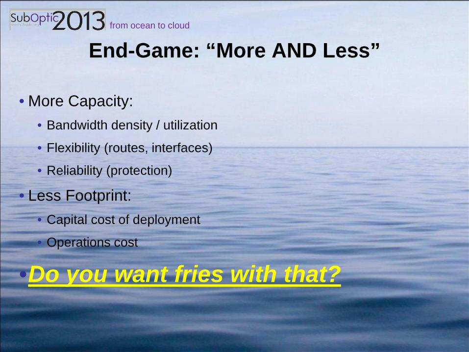
End-Game: “More AND Less”
• More Capacity: • Bandwidth density / utilization
• Flexibility (routes, interfaces)
• Reliability (protection)
• Less Footprint: • Capital cost of deployment
• Operations cost
•Do you want fries with that?

from ocean to cloud
Questions?
from ocean to cloud
OTN is the next step…
• To achieve all the elements of the “End-Game”, expanded OTN is necessary on Undersea Cables
• Several upgrades of existing networks adopting initial OTN capabilities, principally at client interface
• Need to push to the next step full OTN deployment
• To outline some of the impacts, it is first necessary to review the basic structure of OTN in a capacity management context

from ocean to cloud
Optical Transport Network (G872, G709)
from ocean to cloud
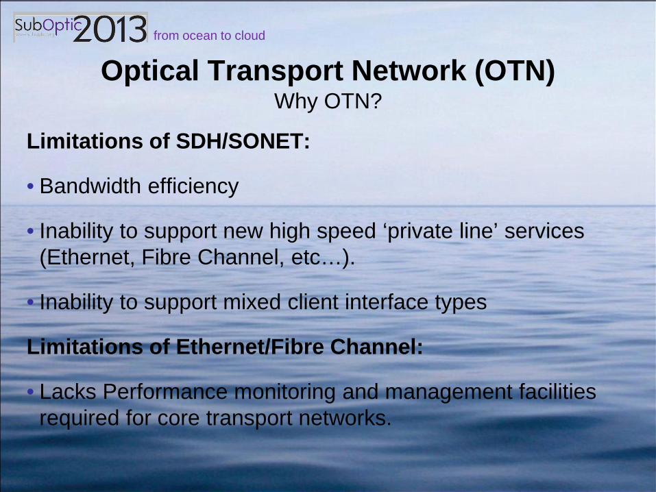
Optical Transport Network (OTN) Why OTN?
Limitations of SDH/SONET:
• Bandwidth efficiency
• Inability to support new high speed ‘private line’ services (Ethernet, Fibre Channel, etc…).
• Inability to support mixed client interface types
Limitations of Ethernet/Fibre Channel:
• Lacks Performance monitoring and management facilities required for core transport networks.

from ocean to cloud
Optical Transport Network (OTN) Why OTN?
The OTN was defined by the ITU-T in the standards G.872 and G.709 with the intention of bringing together the benefits of SDH/SONET with the increased capacity offered by DWDM and the efficiency of packet based transmission technologies.
G.872 illustrates the network architecture of OTN, whereas G.709 focuses on structure, interfaces, and mapping and is based on the architecture defined in G.872.

from ocean to cloud
Optical Transport Network (OTN) Structure – The Digital Wrapper

from ocean to cloud
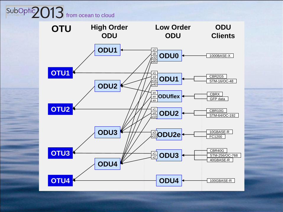
Optical Transport Network (OTN) Structure – multiplexing levels
from ocean to cloud
OTU High Order ODU
Low Order ODU
ODU Clients
1000BASE-X
CBR2G5 STM-16/OC-48
CBRX GFP data
10GBASE-R FC1200
CBR10G STM-64/OC-192
CBR40G STM-256/OC-768 40GBASE-R
100GBASE-R
OTU1
OTU2
OTU3
OTU4
ODU1
ODU2
ODU3
ODU4
ODU1
ODU0
ODUflex
ODU2
ODU2e
ODU3
ODU4
x1 x2
x3 x10
x1 x4
x10
xn xn xn
x1 x4
x16 x40
x2 x8
x32 x80

from ocean to cloud
OTN Hierarchy: “Building Blocks”
• In an OTN network, Reference Rate = basic signal rate (e.g. “building blocks”) used to plan and manage:
• Capacity
• Structure
• Interface equipment
OTU ODU “Reference” Rate
Actual Rate (OTU)
Payload Rate (OPU)
0 1.25 Gb/s n/a 1.238 Gb/s
1 1 2.5 Gb/s 2.666 Gb/s 2.488 Gb/s
2 2 10 Gb/s 10.709 Gb/s 9.953 Gb/s
3 3 40 Gb/s 43.018 Gb/s 39.813 Gb/s
4 4 100 Gb/s 111.809 Gb/s 104.794 Gb/s

from ocean to cloud
Combining High and Low Order ODU
• High Order is functional equivalent of Pre-OTN SLTE
• Low Order is functional equivalent of Pre-OTN ADM / “local MUX”
• Can we integrate the two functions into one network element (efficiency and cost savings)?

from ocean to cloud
Questions?

from ocean to cloud
LAN/WAN PHY Ethernet
from ocean to cloud
LAN/WAN PHY Ethernet
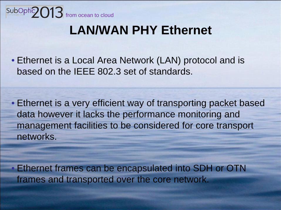
• Ethernet is a Local Area Network (LAN) protocol and is based on the IEEE 802.3 set of standards.
• Ethernet is a very efficient way of transporting packet based data however it lacks the performance monitoring and management facilities to be considered for core transport networks.
• Ethernet frames can be encapsulated into SDH or OTN frames and transported over the core network.

from ocean to cloud
LAN/WAN PHY Ethernet
LAN/WAN PHY Ethernet refers to the IEEE 802.3ae standard which defined the following physical specifications for 10Gbit/s Ethernet interfaces:
These are Client interface specifications that allow SLTE to connect directly to Ethernet enabled networking equipment (IP routers, bridges etc..).
Standard Description Wavelength Reach 10GBASE-LR long reach 1310 nm 10 km 10GBASE-ER extended reach 1550 nm 40 km
from ocean to cloud
LAN PHY vs WAN PHY What’s the difference?
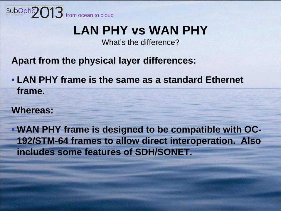
Apart from the physical layer differences:
• LAN PHY frame is the same as a standard Ethernet frame.
Whereas:
• WAN PHY frame is designed to be compatible with OC-192/STM-64 frames to allow direct interoperation. Also includes some features of SDH/SONET.

from ocean to cloud
Questions?

from ocean to cloud
Pass-through SLTEs
Refers to an SLTE configuration that is capable of passing traffic fro ‘east’ to ‘west’ line interfaces transparently without terminating the client signal.

from ocean to cloud
• Optical Bypass: Wavelengths that transit a station without client ports / ODF
• Cost/Benefit: + Reduces client interface cost
• DECREASE in design capacity
• Restricts Routing capabilities
• Strands capacity: adequate demand in “combined segment?”
Cable Station X
(VS.) SLTE-S1
D W D M
Client
Backhaul
Line
40G 10G 10G 10G 10G Segment S2
Segment S1
Standard Segment Interconnect
40G 10G 10G 10G 10G
SLTE-S2
D W D M
Client Line
40G 10G 10G 10G 10G
40G 10G 10G 10G 10G
Cable Station X
SLTE-S1
D W D M
Client
Backhaul
Line
40G Segment S2
Segment S1
Optical Bypass
40G 10G 10G 10G 10G
SLTE-S2
D W D M
Client Line
40G
40G 10G 10G 10G 10G
from ocean to cloud
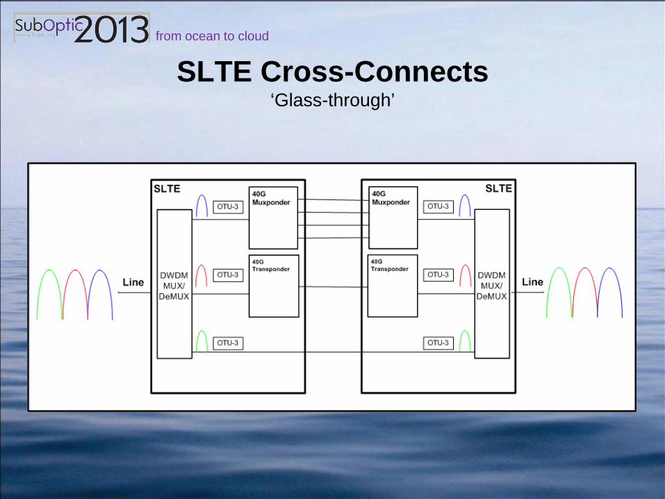
SLTE Cross-Connects ‘Glass-through’
Refers to an SLTE configuration that is capable of passing traffic for ‘east’ to ‘west’ line interfaces transparently without terminating the line or client signal.
from ocean to cloud
SLTE Cross-Connects ‘Glass-through’
from ocean to cloud
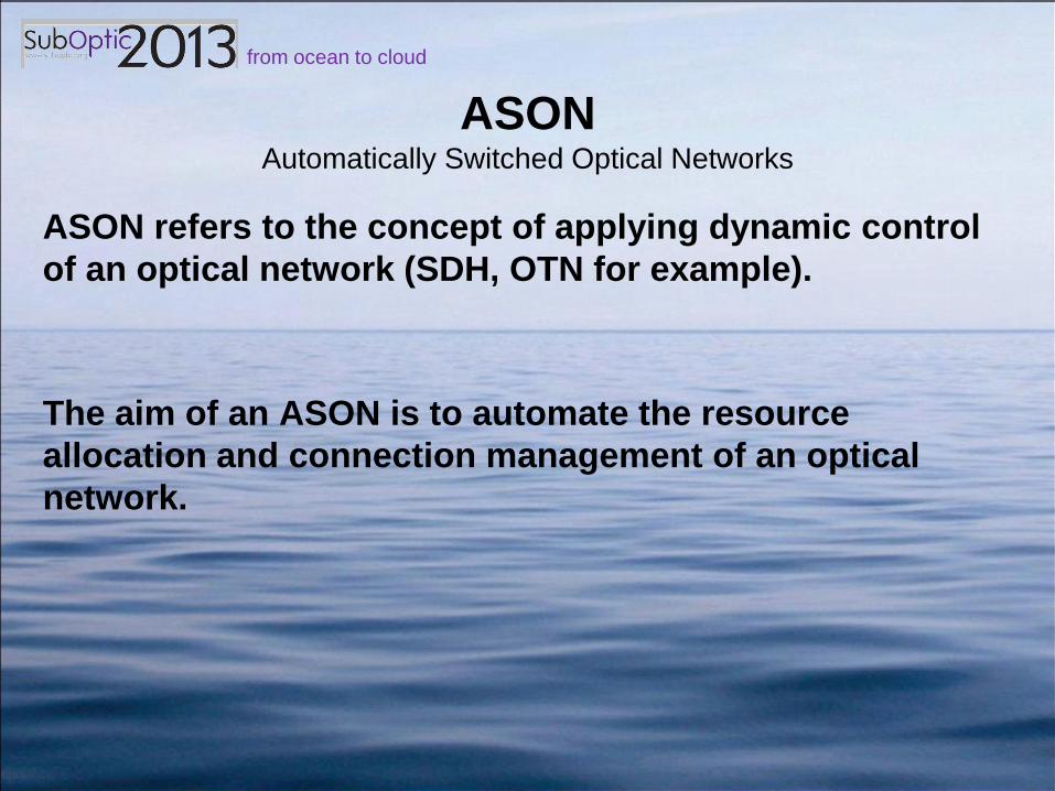
ASON Automatically Switched Optical Networks
ASON refers to the concept of applying dynamic control of an optical network (SDH, OTN for example).
The aim of an ASON is to automate the resource allocation and connection management of an optical network.

from ocean to cloud
ASON Traditional Optical Networks vs ASONs
• In traditional Optical Networks (using SNCP, MSP, MS-SPRing), protection capacity is pre-assigned and traffic switches to the pre-assigned capacity upon failure.
• In ASONs a control plane is implemented that has intelligence of the wider network and upon a failure it dynamically assigns a restoration route.

from ocean to cloud
ASON The Control Plane
In an ASON a control plane is required to manage the restoration of traffic dynamically.
Using the GMPLS standards is a popular way to do this
from ocean to cloud
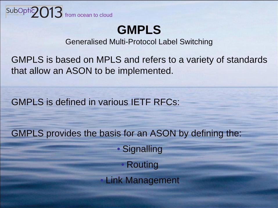
GMPLS Generalised Multi-Protocol Label Switching
GMPLS is based on MPLS and refers to a variety of standards that allow an ASON to be implemented.
GMPLS is defined in various IETF RFCs:
GMPLS provides the basis for an ASON by defining the:
• Signalling
• Routing
• Link Management

from ocean to cloud
Questions?

from ocean to cloud
Implementation and Network Administration of these Standards

from ocean to cloud
INEFFICIENT Backhaul
• SDH networks have suffered from the misconception that wet bandwidth = client interface
• OTN networks could suffer the same fate!
• Costly: increased footprint, collocation and interconnection • Example, same POP yet multiple clients / collocation fibers
Carrier X POP Carrier X Colo SLTE-OTN
D W D M
ODU3
Line Client ODU2 OTU2 ODU2 OTU2 ODU2 OTU2 ODU1 OTU1 ODU1 OTU1 ODU1 OTU1 ODU1 OTU1
ODU-n
Carrier X
ODU-n
ODU2 OTU2 ODU2 OTU2 ODU2 OTU2 ODU1 OTU1 ODU1 OTU1 ODU1 OTU1 ODU1 OTU1
Carrier X B/H Customer
Carrier Y Carrier Y
B/H Customer B/H Customer
Collocation Fibers
ODU3

from ocean to cloud
EFFICIENT Backhaul
• Significant reduction in client port / collocation fiber usage
• Benefit: savings in client ports, space/power, collocation fibers, interconnect fees
• Drive up the scale of physical backhaul! • Requires better communication between backhaul providers and wet-
capacity owners
Carrier X POP Carrier X Colo SLTE-OTN
D W D M
ODU3
Line Client ODU2 ODU2 ODU2
OTU3 ODU1 ODU1 ODU1 ODU1
ODU-n
Carrier X
ODU-n
ODU2 ODU2 ODU2
OTU3 ODU1 ODU1 ODU1 ODU1
Carrier X B/H Customer
Carrier Y Carrier Y
B/H Customer B/H Customer
Collocation Fibers
ODU3

from ocean to cloud
Individual DLS: “Simple” DWDM and Client
• Separate client port for each client signal, whether terminating or passing through.
• No efficiency in the backhaul.
• $$$$$$$$$$$
SLTE-EAST SLTE-WEST
D W D M
Line Client ODU2 OTU2 ODU2 OTU2
ODU2 OTU2
ODU1 OTU1 ODU1 OTU1 ODU1 OTU1 ODU1 OTU1
Segment 1 ODU4
ODU2 OTU2 ODU2 OTU2
ODU2 OTU2
ODU1 OTU1 ODU1 OTU1 ODU1 OTU1 ODU1 OTU1
ODU4
Client
D W D M
Line
Segment 2
BACKHAUL

from ocean to cloud
Multiple DLS: “Complex” Muxing
• No client ports for pass-through ODU-n = cost savings. • Same benefit as Optical bypass without the adverse impacts
• Backhaul to multiple directions of client signal = flexibility
• “Smart” SLTE recreating Automated protection capability
SLTE-OTN
D W D M
Line-West ODU2 ODU2
ODU2
ODU1 ODU1 ODU1 ODU1
Segment 1 ODU4
ODU2 ODU2
ODU2
ODU1 ODU1 ODU1 ODU1
ODU4
Client
D W D M
Line-East
Segment 2
BACKHAUL
OTU
3

from ocean to cloud
DWA Manual Protection
• DWA is an unprotected signal
• Acquire wavelengths on multiple segments to create protection route
• Idea: carrier provision both routes (A-B and A-C-B) with backhaul to a POP, and then implement their own protection switching
• Reality: provision only the primary route, request “emergency provisioning” around a failure
Station B
S L T E
Client
Backhaul S L T E
Client
Station A
S L T E
Client
Backhaul S L T E
Client
Station C
S L T E
Client S L T E
Client
Seg. 3
Seg. 1
Seg. 2
X

from ocean to cloud
DWA Manual Protection: ISSUES
• Costly: client ports, backhaul in the back-up route
• Slow: manual patching
• Inefficient: restore the whole wave
• Emergency provisioning is an operational nuisance

from ocean to cloud
DWA Automated Protection
• Span and Ring Protection
• Customized auto-protection switching • Protection bandwidth does not require client ports
• Switched (NOT patched), restore specific ODU-n
SLTE-OTN
D W D M
ODU4
Line Client ODU2 ODU2 ODU2
OTU3
ODU4
SLTE-OTN
D W D M
ODU4
Line-West
Client
OTU
3
D W D M
Line-East
ODU4
ODU4
EAST
WEST
Single Line Segment Multiple Line Segment
WEST Segm
ent
- Or -
ODU2 X X
OD
U2
OD
U2
OD
U2
OD
U2

from ocean to cloud
DWA Automated Protection
• Less expensive: No client ports at A, B, and C
• Fast: switching, not patching
• Efficient: Restore specific ODU-n in different wavelengths
• Planned / Programmed prior to event: no nuisance orders
Station A
SLTE-OTN
Station C
SLTE-OTN
D W D M
ODU-n
Backhaul D W D M
ODU-n
D W D M
ODU-n D W D M
ODU-n
Seg. 3
Seg. 1
Seg. 2
OTU-n
Station B
SLTE-OTN D W D M
ODU-n
Backhaul D W D M
ODU-n
OTU-n
from ocean to cloud
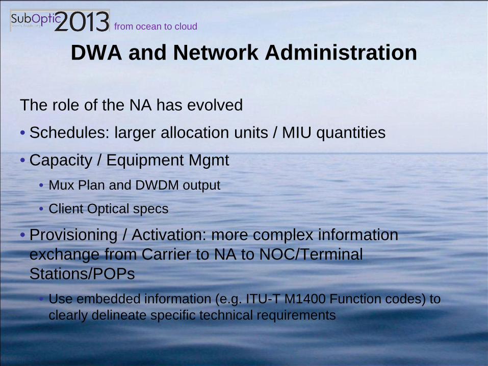
DWA and Network Administration
The role of the NA has evolved
• Schedules: larger allocation units / MIU quantities
• Capacity / Equipment Mgmt • Mux Plan and DWDM output
• Client Optical specs
• Provisioning / Activation: more complex information exchange from Carrier to NA to NOC/Terminal Stations/POPs
• Use embedded information (e.g. ITU-T M1400 Function codes) to clearly delineate specific technical requirements

from ocean to cloud
ITU-T Function Codes for Ethernet
• New in M1400 for 2013
• Several undersea cables now using these function codes for activation purposes
Bit Rate Function Code Description 1 Gb/s GE1 1Gigabit Ethernet
2.5 Gb/s GE2X 2.5 Gigabit Ethernet 10 Gb/s GE10L 10 Gigabit Ethernet LAN
GE10W 10 Gigabit Ethernet WAN 40 Gb/s GE40L 40 Gigabit Ethernet LAN
GE40W 40 Gigabit Ethernet WAN 100 Gb/s GE100L 100 Gigabit Ethernet LAN
GE100W 100 Gigabit Ethernet WAN

from ocean to cloud
Upgrade to DWA
Many networks adopt DWA as part of an Upgrade strategy
• Update MIU Accounting Principles (Schedules)
• Highly detailed equipment management
• More elaborate allocation models/schedules
• Another layer of detail, mathematical complexity in NA Support Systems / schedules

from ocean to cloud
Managing Capacity Replacement Costs
• Achieving new design capacity usually requires replacement of existing capacity/equipment
• Cost-causer-cost-payer principle
• Strategy: Allocation and Re-Allocation
• Requires clear book-keeping by NA to properly manage cost sharing

from ocean to cloud
OTN and Network Administration
• Same NA functions on a new scale, greater complexity
• ODU-n as the new MIU: New language, new “math”
• Activation/Provisioning: framing, protection
• ITU-T Function codes for OTN: OTU1, OTU2, OTU3, OTU4 • TERMA/AAA-TERMZ/ZZZ OTU2 001
• NA Support Systems have to evolve • Future proof NA systems by designing for transition to 40G then
100G, then ???

from ocean to cloud
OTN in NA Capacity/Accounting Systems
• Network Administrator (NA) uses reference rates and corollary ODU as “Building Blocks” in capacity accounting
OTU ODU “Reference” Rate
Eqv SDH in NA Systems
0 1.25 Gb/s STM-8 1 1 2.5 Gb/s STM-16 2 2 10 Gb/s STM-64 3 3 40 Gb/s STM-256 4 4 100 Gb/s STM-640

from ocean to cloud
Data Efficient Transmission • SDH networks are not efficient for transmission of packet
based data.
• There are also inefficiencies in DWDM systems such as • Un-utilised ‘equipped’ capacity
• Un-untilised ‘surplus’ capacity
• Unbalanced traffic flows

from ocean to cloud
Data Efficient Transmission
• Un-utilised ‘equipped’ capacity refers to how efficient users are at filling their allocated capacity.
• Un-utilised ‘surplus’ capacity refers to capacity that is installed and equipped but not in use.

from ocean to cloud
Data Efficient Transmission • Unbalanced traffic profiles

from ocean to cloud
Data Efficient Transmission
Submarine cable systems are not currently designed to mitigate these inefficiencies.
Does the answer to this lie outside of layer 1/2?

from ocean to cloud
Data Efficient Transmission Consider an IP-VLAN network:

from ocean to cloud
Data Efficient Transmission
Submarine cable systems are not currently designed to mitigate these inefficiencies.
Does the answer to this lie outside of layer 1/2?

from ocean to cloud
Data Efficient Transmission
Each operator is assigned a separate VLAN on the network Minimum Investment Unit is the lowest access bandwidth possible on the client side VLAN ports. This VPN bandwidth is guaranteed using CoS to prioritise traffic. Each VPN bandwidth can exceed the guaranteed maximum when excess capacity exists in other VLANs.

from ocean to cloud
Data Efficient Transmission
This configuration would:
• Allow the submarine cable capacity to be used as a shared resource.
• Require a different operating and ownership model
• Mitigate the inefficiencies of packet based data transmission
