dvr manual - products, projects, rental · you must read the scc-2drvl-dvr manual before using the...
TRANSCRIPT
Seascape BVDe Hoogjens 22
4254 XW SleeuwijkThe Netherlands
Phone: +31-183-307900Email: [email protected]
www.novasub.comwww.seascape.nl
SCC
-2D
RVL
-DVR
Man
ual
Version: 1.53Date: 24-Feb-16
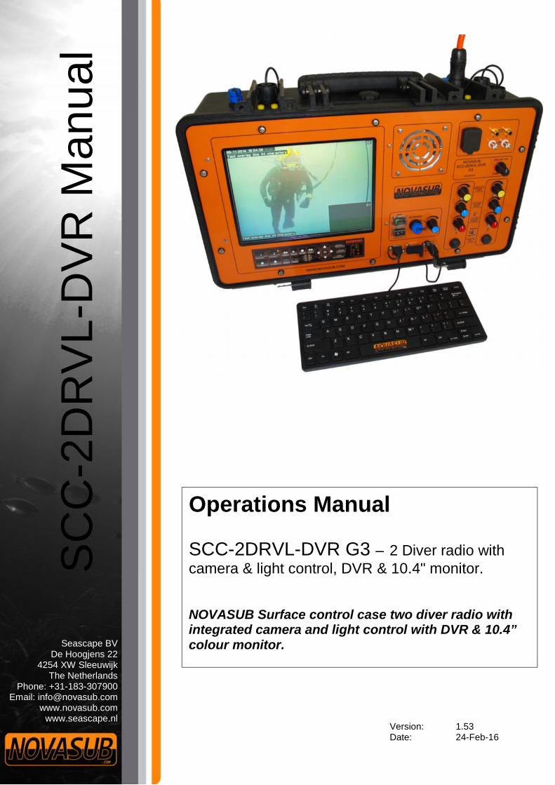
Operations Manual
SCC-2DRVL-DVR G3 – 2 Diver radio withcamera & light control, DVR & 10.4" monitor.
NOVASUB Surface control case two diver radio withintegrated camera and light control with DVR & 10.4”colour monitor.

Version: 1.53 Date:24-Feb-16
SCC-2DRVL-DVR G3 MANUAL1 of 56
Index1 HELP & SUPPORT ..............................................................................................................................................................................5
2 SAFETY MEASUREMENTS..................................................................................................................................................................6
SAFETY PRECAUTIONS............................................................................................................................................................................. 6
3 MAINTENANCE .................................................................................................................................................................................7
3.1.1 Maintenance by authorized dealer or distributor ........................................................................................................................ 7MAINTENANCE SCHEME.......................................................................................................................................................................... 7
4 WARRANTY ......................................................................................................................................................................................8
WARRANTY PERIOD ............................................................................................................................................................................... 8EXCLUSIONS AND LIMITATIONS ................................................................................................................................................................ 8THIS LIMITED WARRANTY IS NOT ENFORCEABLE IF ITEM: ............................................................................................................................... 8LIMITATION OF LIABILITY......................................................................................................................................................................... 8
5 GLOSSARY.........................................................................................................................................................................................9
VIDEO FORMAT..................................................................................................................................................................................... 9DVR INTRODUCTION ............................................................................................................................................................................. 9VIDEO OVERLAY WITH AND WITHOUT DARK BACKGROUND ........................................................................................................................... 10
6 GENERAL SPECIFICATIONS ..............................................................................................................................................................10
DVR SPECIFICATIONS ........................................................................................................................................................................... 11RECORDING INFORMATION....................................................................................................................................................................11
6.2.1 File name.................................................................................................................................................................................... 116.2.2 Recording file size ...................................................................................................................................................................... 11
7 OPTIONAL.......................................................................................................................................................................................12
BOBOX ............................................................................................................................................................................................ 12TMIC 1&2 ........................................................................................................................................................................................ 12
7.2.1 Tmic1.......................................................................................................................................................................................... 127.2.2 Tmic2.......................................................................................................................................................................................... 12
NSHEADSET1, NOISE CANCELLATION HEADSET ....................................................................................................................................... 13SENSOR DATA INPUT ON VIDEO OVERLAY ................................................................................................................................................. 13
7.4.1 UDS-1 Underwater Depth sensor ............................................................................................................................................... 137.4.2 UDS-3 Underwater Depth sensor ............................................................................................................................................... 13
THICKNESS GAUGE (T) ......................................................................................................................................................................... 14CP PROBE (CP)................................................................................................................................................................................... 14THIRD PARTY CAMERA CONNECTION........................................................................................................................................................ 14LOW VOLTAGE POWER SUPPLY ............................................................................................................................................................... 14
8 GENERAL FUNCTIONS .....................................................................................................................................................................15
MAIN POWER..................................................................................................................................................................................... 15DIVER COMMUNICATIONS..................................................................................................................................................................... 16
8.2.1 2 wire comms configuration ...................................................................................................................................................... 168.2.2 4 wire comms configuration ...................................................................................................................................................... 168.2.3 2/4S - 2 wire simplex ..................................................................................................................................................................168.2.4 4HD – 4 wire Half Duplex ........................................................................................................................................................... 168.2.5 4FD- 4 wire Full Duplex .............................................................................................................................................................. 168.2.6 Comms Volume control .............................................................................................................................................................. 178.2.7 Internal MIC ............................................................................................................................................................................... 178.2.8 Push To Talk (PTT) ...................................................................................................................................................................... 178.2.9 Cross-Talk................................................................................................................................................................................... 17
INTERNAL SPEAKER .............................................................................................................................................................................. 17EXTERNAL SPEAKER ............................................................................................................................................................................. 17HEADSET / MIC .................................................................................................................................................................................. 18KEYPAD CONTROL................................................................................................................................................................................ 19MOUSE FUNCTION DESCRIPTIONS ........................................................................................................................................................... 20
9 MAIN OPERATIONS.........................................................................................................................................................................21
Version: 1.53 Date:24-Feb-16
SCC-2DRVL-DVR G3 MANUAL2 of 56
SYSTEM STARTUP ................................................................................................................................................................................ 21VIEW ................................................................................................................................................................................................ 21
9.2.1 PAP............................................................................................................................................................................................. 219.2.2 PIP .............................................................................................................................................................................................. 22
9.2.2.1 PIP window view control ....................................................................................................................................................................... 22VIDEO TEXT OVERLAY .......................................................................................................................................................................... 23CAMERA AND LIGHT CONTROL................................................................................................................................................................ 24
9.4.1 Camera signal ............................................................................................................................................................................ 249.4.1.1 Why use video transmission over Twisted pair ..................................................................................................................................... 24
9.4.2 Light controller........................................................................................................................................................................... 24RECORDING........................................................................................................................................................................................ 25SNAPSHOT ......................................................................................................................................................................................... 25PLAYBACK .......................................................................................................................................................................................... 26
9.7.1 Playback status Bar....................................................................................................................................................................269.7.2 Keypad & Keyboard control during playback............................................................................................................................. 279.7.3 Mouse control during playback.................................................................................................................................................. 27
AUDIO TO SPEAKER.............................................................................................................................................................................. 27BACKUP/COPY FILES ............................................................................................................................................................................ 27SNAPSHOT BACKUP/COPY FILES ............................................................................................................................................................. 28
10 INTERNAL DVRP2 MENU SETTINGS.................................................................................................................................................29
MAIN MENU DVR2 ............................................................................................................................................................................ 29MENU DESCRIPTION............................................................................................................................................................................. 30
10.2.1 Main Menu access .................................................................................................................................................................3010.2.2 Maintenance Menu ............................................................................................................................................................... 3010.2.3 Intern Overlay ........................................................................................................................................................................ 3010.2.4 Info......................................................................................................................................................................................... 3010.2.5 Channel Offset ....................................................................................................................................................................... 3010.2.6 Reset settings......................................................................................................................................................................... 3010.2.7 Firmware Update...................................................................................................................................................................3010.2.8 Channel settings (1,2,3 or 4).................................................................................................................................................. 3010.2.9 Show DSI Depth ..................................................................................................................................................................... 3010.2.10 Show DDG Depth ...................................................................................................................................................................3010.2.11 Show DDG time...................................................................................................................................................................... 3010.2.12 Set light Type ......................................................................................................................................................................... 31
11 DVR MAIN MENU ...........................................................................................................................................................................32
1 CHANNEL (1 CH) ............................................................................................................................................................................. 32PIP ..................................................................................................................................................................................................32
11.2.1 PIP window view control........................................................................................................................................................ 32PAPH............................................................................................................................................................................................... 32PAPV............................................................................................................................................................................................... 32ELEC ZOOM........................................................................................................................................................................................ 33SPOT ................................................................................................................................................................................................ 33SNAPSHOT BACKUP .............................................................................................................................................................................. 33PLAYBACK .......................................................................................................................................................................................... 34BACKUP............................................................................................................................................................................................. 34
RECORD ........................................................................................................................................................................................ 34MUTE........................................................................................................................................................................................... 34MENU .......................................................................................................................................................................................... 34
11.12.1 Value editing control ............................................................................................................................................................. 3511.12.1.1 How to add or edit a value with the keypad: ................................................................................................................................... 35.................................................................................................................................................................................................................................. 3511.12.1.2 How to add or edit a value with the Mouse: .................................................................................................................................... 35
11.12.2 Tools ...................................................................................................................................................................................... 3611.12.2.1 HDD .................................................................................................................................................................................................. 3611.12.2.2 User .................................................................................................................................................................................................. 3611.12.2.3 Default.............................................................................................................................................................................................. 3611.12.2.4 Upgrade............................................................................................................................................................................................ 3611.12.2.5 Time.................................................................................................................................................................................................. 3611.12.2.6 Info ................................................................................................................................................................................................... 3611.12.2.7 Maintenance .................................................................................................................................................................................... 36
Version: 1.53 Date:24-Feb-16
SCC-2DRVL-DVR G3 MANUAL3 of 56
11.12.3 Setup...................................................................................................................................................................................... 3611.12.3.1 Setup Menu ...................................................................................................................................................................................... 3611.12.3.2 Record Menu.................................................................................................................................................................................... 3811.12.3.3 Video Menu ...................................................................................................................................................................................... 3911.12.3.4 Network Menu ................................................................................................................................................................................. 39
12 USING THE DVR ON A NETWORK ....................................................................................................................................................40
CONNECTING THE SCC-2DRVL-DVR TO NETWORK...................................................................................................................................4012.1.1 Local PC LAN connection........................................................................................................................................................ 4012.1.2 Network connection............................................................................................................................................................... 40
CONNECTING TO DVR.......................................................................................................................................................................... 41NETWORK DVR CONTROL..................................................................................................................................................................... 41
12.3.1 Image control ........................................................................................................................................................................ 42CONFIGURE........................................................................................................................................................................................ 43
12.4.1 Server parameters .................................................................................................................................................................4312.4.2 Channel Parameters .............................................................................................................................................................. 4412.4.3 Alarm parameters..................................................................................................................................................................4512.4.4 User Info Parameters............................................................................................................................................................. 4512.4.5 Other settings ........................................................................................................................................................................ 46
PLAYBACK .......................................................................................................................................................................................... 4712.5.1 Search files............................................................................................................................................................................. 4712.5.2 Download files ....................................................................................................................................................................... 47
13 QUICK START GUIDE .......................................................................................................................................................................48
14 VIDEO TEXT OVERLAY BASIC INSTRUCTIONS...................................................................................................................................49
15 PANEL CONNECTIONS.....................................................................................................................................................................50
DVR USB ......................................................................................................................................................................................... 50DVR LAN ......................................................................................................................................................................................... 50KEYBOARD ......................................................................................................................................................................................... 50VIDEO OUT ........................................................................................................................................................................................ 50AUDIO OUT ....................................................................................................................................................................................... 50HDMI OUTPUT................................................................................................................................................................................... 50MIC/HEADSET.................................................................................................................................................................................... 50
16 TOP CONNECTIONS.........................................................................................................................................................................51
POWER SUPPLY ................................................................................................................................................................................... 51MAIN CABLE CONNECTION ....................................................................................................................................................................51
16.2.1 Standard connector, SCC-01-10c/11c ....................................................................................................................................5116.2.2 Connector with sensor data, SCC-01-10d/11d....................................................................................................................... 5216.2.3 Amphenol connector, SCC-01-10b/11b..................................................................................................................................5216.2.4 Amphenol connector, SCC-01-10e/11e..................................................................................................................................5316.2.1 Comms Banana sockets ......................................................................................................................................................... 5316.2.2 Ext. Speakers.......................................................................................................................................................................... 53
OPTIONAL EXTRA CONNECTORS .............................................................................................................................................................. 5416.3.1 Data In connection RS232, SCC-01-49 ...................................................................................................................................5416.3.2 Data In/Out connection to DDG, SCC-01-50 .......................................................................................................................... 54
16.3.2.1 UDS-3 connected to SCC ....................................................................................................................................................................... 5416.3.2.2 UDS-3 connected to DDG ...................................................................................................................................................................... 54
16.3.3 BoBox..................................................................................................................................................................................... 5516.3.4 Low voltage DC power supply................................................................................................................................................ 55

Version: 1.53 Date:24-Feb-16
SCC-2DRVL-DVR G3 MANUAL4 of 56
WARNINGYOU MUST READ the SCC-2DRVL-DVR manual before using the SCC-2DRVL-DVR. Failure todo so may lead to improper use, serious injury or death. Care should be taken to follow theinstructions correctly and also conduct a separate risk assessment prior to commencing work
WARNING Is used in connection with a procedure or situation that may result in seriousinjury or death.
CAUTION Is used in connection with a procedure or situation that will result in damageto the product.
NOTE! Is used to emphasize important information.
Disposal of the device
Please dispose of the device in an appropriate way, treating it as electronic waste. Do not throw it in the garbage. Ifyou wish, you may return the device to your nearest Novasub dealer.
Version: 1.53 Date:24-Feb-16
SCC-2DRVL-DVR G3 MANUAL5 of 56
1 Help & SupportFirst please read this manual thoroughly. Further details about a Warranty Statement can be found at the chapter 4 -Warranty.
For technical support contact your local a Novasub Authorized Service Center or Seascape BV.
Seascape BVDe Hoogjens 22NL-4254 XW SleeuwijkThe NetherlandsT. +31-183-307900F. +31-183-307910E. [email protected]
Copyright © Seascape BVAll Rights reserved.
If you have cause to use our technical support service, please make ensure that you have the following details at hand prior tocalling:
• system serial number• firmware version and build number• fault description• any remedial action implemented

Version: 1.53 Date:24-Feb-16
SCC-2DRVL-DVR G3 MANUAL6 of 56
2 Safety measurementsThe content of this manual may be changed without prior notices. Seascape cannot under any circumstances be held liable forany special, indirect or incidental damages in connection with, or as a result of the purchase or use of this product and itemsthat come.
Safety precautionsDo not attempt to use the SCC-2DRVL-DVR without reading this instruction manual in its entirety, including all the warnings. Make surethat you fully understand the use, displays and limitations of the instrument. If you have any questions about the manual or the SCC-2DRVL-DVR, contact your Novasub Authorized Service Center before using the SCC-2DRVL-DVR.
Always remember that YOU ARE RESPONSIBLE FOR YOUR OWN SAFETY!

Version: 1.53 Date:24-Feb-16
SCC-2DRVL-DVR G3 MANUAL7 of 56
3 MaintenanceThe SCC-2DRVL-DVR is a semi ruggedized case. Although it is designed to withstand rough circumstances, you must treat it with the sameproper care and caution as any other electronic instrument.
3.1.1 Maintenance by authorized dealer or distributorHave your SCC-2DRVL-DVR serviced by a Novasub Authorized Service Center. This service will include a general operational check,replacement of the battery, and overall upgrade of firmware. The service requires special tools and training.
Maintenance scheme
By CustomerCleaning SCC-2DRVL-DVR When neededDrying panels During operations and
before storingCharging battery Regularly
By Novasub Authorized Service CenterServicing SCC-2DRVL-DVR 2 yearsInternal backup battery replacement 2 Yearly
WARNING
• It is not allowed to disassemble the SCC-2DRVL-DVR or to repair the product by unqualified personal or disassemblepart, in that case all warranties are void.
• Avoid large amount of water on the control and monitor panels.• DO NOT use the SCC-2DRVL-DVR if you detect any moisture or water inside.
CAUTION
• Protect the unit from shock, extreme heat, direct sunlight, and chemical attack.• The SCC-2DRVL-DVR cannot withstand the impact of heavy objects like air cylinders, nor chemicals like gasoline, cleaning
solvents, aerosol sprays, adhesive agents, paint, acetone, alcohol, etc. Chemical reactions with such agents will damage theseals, case and finish.
• Do not use compressed air to blow water off the unit.
NOTE!
The SCC-2DRVL-DVR is not fully waterproof, it can withstand some water drops on the monitor panel and controlpanel. Be sure to whip off any water drops or moisture from the panels.

Version: 1.53 Date:24-Feb-16
SCC-2DRVL-DVR G3 MANUAL8 of 56
4 WarrantyNovasub warrants that during the Warranty Period Novasub or a Novasub Authorized Service Center (hereinafter Service Center) will, atits sole discretion, remedy defects in materials or workmanship free of charge either by a) repairing, or b) replacing, or c) refunding,subject to the terms and conditions of this Limited Warranty. This Limited Warranty is only valid and enforceable in the country ofpurchase, unless local law stipulates otherwise.
Warranty PeriodThe Limited Warranty Period starts at the date of original retail purchase. The Warranty Period is two (2) years for the SCC-2DRVL-DVR.Warranty applies only on manufacturing defaults. The Warranty Period is one (1) year for accessories, including mounting hardware andconnector cables.
Exclusions and LimitationsThis Limited Warranty does not cover:
1. a) normal wear and tear;b) defects caused by rough handling or;c) defects or damage caused by misuse contrary to intended or recommended use;
2. user manuals or any third-party items;3. defects or alleged defects caused by the use with any product, accessory, software and/or service not manufactured or supplied
by Novasub;4. battery (only first 6 month after purchase is under warranty).
This Limited Warranty is not enforceable if item:1. has been opened beyond intended use;2. has been repaired using unauthorized spare parts; modified or repaired by unauthorized Service Center;3. serial number has been removed, altered or made illegible in any way, as determined at the sole discretion of Novasub;4. has been exposed to chemicals or excessive water spraying. Novasub does not warrant that the operation of the product will be
uninterrupted or error free, or that the product will work with any hardware or software provided by a third party.
Limitation of LiabilityTo the maximum extent permitted by applicable mandatory laws, this Limited Warranty is your sole and exclusive remedy and is in lieu ofall other warranties, expressed or implied. Novasub shall not be liable for special, incidental, punitive or consequential damages,including but not limited to loss of anticipated benefits, loss of data, loss of use, cost of capital, cost of any substitute equipment orfacilities, claims of third parties, damage to property resulting from the purchase or use of the item or arising from breach of thewarranty, breach of contract, negligence, strict tort, or any legal or equitable theory, even if Novasub knew of the likelihood of suchdamages. Novasub shall not be liable for delay in rendering warranty service.

Version: 1.53 Date:24-Feb-16
SCC-2DRVL-DVR G3 MANUAL9 of 56
5 GlossaryThe Surface Control Case (SCC) is a rugged case with the built in NSDVR2 hard disk recorder. The Novasub divercommunication radio is based on the latest electronic technology and is specially designed for an outstanding diver andsurface sound quality. The unit is standard fitted for a 2 diver connection and has a built in LED light control and videotransmission over twisted pair or coax controller for each diver (CCTV).
The video controller is auto tunable for any cable up to 600 m. The unit has a mains and battery backup. Is powered with abuilt in smart battery charger and has a battery state condition monitoring. Standard the radio is fitted with a volumecontrollable external speaker amplifier. Both diver and tender voice are heard on the external speaker.
The radio is based on a 2 wire communication principal and has for each diver a PTT (Push To Talk) button. Thecommunication type is “simplex”, that is to say; the operator must press a button to speak. The sound of the diver is alwaysheard, except when operators speaks to the diver. The operator at the surface can speak to each diver individually. Also theoperator can activate the communication diver-diver (Cross Talk). The SCC can also be set for Round-Robin (4 wire comms).Each diver audio and video have an output for extra monitors and recording.
Video format
The DVR2 can record either in the standard D1 format or the new 960H wide format. The 960H format is in PAL 960x576pixels, compared to the D1 720x576 and increase of 35%. To really achieve the actual 960H resolution, use the latestNovasub NSBC cameras which actually have the 960x576 pixels resolution.
DVR IntroductionThe NSDVR2 is based on an embedded processor and embedded operating system with a solid state hard drive for recordingthe files. The NSDVR2 will be able to record one Channel at D1 and the New WD1 video standard resolution. The WD1 is a960H video resolution which records the video image in a resolution of 944x576 pixels @ 20 fps. Using the new 700 TVLNovasub video cameras, you will be able to record this WD1 (960H) resolution.The NS-DVR2 has a VGA and HMDI output to a monitor. The SCC cases uses the VGA output for the internal monitor. TheHDMI output can be used to connect a second monitor. On the second monitor you will see a duplicate of the main monitor(VGA). The NSDVR2 has a built in Date &time &Data text overlay line , channel name text overlay, and 2x free text lines videooverlay.The NS-DVR2 is menu controlled either by a mouse or the dedicated Novasub keypad. Recording is selected per channel bykeypad button, or mouse control through the menu.The video files are recorded on a Solid-state hard disk (SSD). Also a snapshot can be made and is also stored on the SSD.The SCC-2DRVL-DVR has an audio input which is recorded in the video file. Both files, the video files and snapshot files canbe back upped to a USB-storage device, either an external hard disk or a USB-memory stick. The video files are back uppedas a AVI format with a H264 compression.The NS-DVR2 has a built in Player to playback at your recorded files.The NS-DVR2 also has a network connection which makes it possible to stream the video life over the network/internet usinga Browser on a PC, Tablet or Smartphone. Or the supplied CMS-software for viewing, playback and downloading of files.
Features 960H resolution 2 Channel Rec. Daylight Monitor PIP & PAP Text & Data overlay
Snapshot button Camera Control Light Control Network connection

Version: 1.53 Date:24-Feb-16
SCC-2DRVL-DVR G3 MANUAL10 of 56
Video overlay with and without dark backgroundThe video text overlay are 4 lines of 36 characters each. One line is dedicated for use of the date/time with data. 2nd overlay isthe name of the channel plus free text, and the remaining two overlay lines are free text. All overlay lines can be placedanywhere on the window. Also a snapshot can be made and is stored as a JPG on the hard disk. Optional diver data likedepth and divetime can be added to the overlay. (see Novasub DDG Digital Diver Gauge and UDS-3 depth sensor)
6 General SpecificationsSpecifications
Ext. Powersupply
: 100-260 VAC, 50/60 Hz Battery life : 20 hours -> 2 diver comms only2 hours -> 2 Divers Video&DVR1 hours ->1 diver light&Video andDVR
Light control : 100% dimmable per diver, max 30 watts,12-30 vdc
Int. Power supply : 24 vdc rechargeable battery withbattery status indication, UPSfunction
Video out : 1 per diver, 1Vpp/75 Ohm Network : Connection to network, DVRaccessible via Browser
DVR : Solid State HD recording, H264,avi720x576 pixels@25 fps and 944x576pixels@ 20 fps
Tender volumecontrol
: Per diver
Video control : Video transmission over twisted pair orcoax, auto-tune to 600 m, 32 vdc (12,15,24vdc optional)
Monitor : 10,4” Daylight Monitor, 1000candela
DVR control : Panel keypad control & Mouse Recording time : 100 hrs@ 960H best1,2 Gb / hr. (120 Gb SSD-HD)
Audio Out : 1 per diver signal of 1Vpp Ext. speaker : Amplifier 10W/4-8 Ohm with volumecontrol
Diver to diver : Cross-talk switch, full duplex (4 wire) Communication : 2 wire - simplex, 4 wire - full duplexDiver volumecontrol
: Per diver Recording channel : 2 channel, per channel recordbutton
Dimensions : 546x347x247mm @ 16,8 kg Video file : Retrievable with USB memory stick(*.avi) or connection to PC via LAN
ConnectionsAudio out : 2x RCA (Cinch) Extra monitor : HDMIHeadset/Mic : Bulgin 8pin, audio out, Mic in, PTT Video out : 2x BNCKeyboard : USB-A Ext. speaker : 2x Banana screw socketsNetwork : LAN RJ45 Flash drive : USB-APower in : IEC C14 mates with C13 Diver comms : 2x Banana socket per channelUmbilicalconnector
: 2x Multi pin circular connector, comms,camera and light
The DVR keypad has the following function:
Channel selection 1 & 2 : Channel selection for overlay, camera, light and snapshotcontrol
CAM : ON/OFF camera
REC : Start/Stop recording Light (+/-) : ON/OFF, dimmingSNAP : Snapshot picture of video image (same resolution as video) Arrows, OK : Menu control DVRVIEW : Selection of view, full, PIP, PAP Menu : Access to MenuESC : Escape in DVR menu Play, STOP : Access playback of recorded
files

Version: 1.53 Date:24-Feb-16
SCC-2DRVL-DVR G3 MANUAL11 of 56
DVR specificationsOperating System Embedded Linux operating systemSystem Resource 2-channel real-time recording simultaneouslyVideo Standard PAL, NTSCImage Compression H.264Audio Compression ADPCMRecording Mode ManualVideo Search Time search, event search, channel searchBackup Mode USB backup, network downloadVideo Input 2 CH composite videoVideo Output HDMI, 2 channel composite (spot)Audio Input 2chAudio Output 1chRecording Quality PAL: 704x576(D1), 944x576 (WD1) NTSC: 720x480(D1)Snapshot Quality jpeg 720x576 (D1) 960x576 pixels (WD1)Image Control 6-level adjustableRecording Rate PAL: D1 25fps/second, WD1 20 fps (adjustable) NTSC: D1 30fps/second (adjustable)Recording Storage HDD solid-state driveLocal Playback 2x channelUSB Port 2x USB2.0 port, one for data backup, one for mouse connectionNetwork 1x RJ45 LAN connection
Recording information
6.2.1 File nameThe file name is based on the channel number, date and time; chn120140620150802chn1 2014-06-20 15:08:02Channel 1 date TimeThe time is the start time of the recording
6.2.2 Recording file sizeThe files are automatically recorded in max. files size of 260 Mb each. During recording the NSDVR2 will automatically make anew file. If a recording is stopped before reaching the 260Mb file size, the new next recording file size will smaller than the 260mb. For example; if the recording is stopped at a file size of 160 Mb, then the new next recording will have a file size of 260-160 = 100 Mb.For that reason if you will always have smaller file sizes at the beginning and ending of your recordings.
700TVL camera connected:Setting: WD1 (960H), 2,5 Mbps, 20 fps, VBR, ExcellentRecording: 260 Mb , 39 min, static image = 450 Mb/hr.
Settings: WD1 (960H), 2,5 Mbps, 20 fps, CBR, BestRecording: 260 Mb , 13 min, static image. = 1,2 Gb/hr.

Version: 1.53 Date:24-Feb-16
SCC-2DRVL-DVR G3 MANUAL12 of 56
7 Optional Diver depth to overlay ; direct connection of UDS-3 depth sensor data to video overlay. DDG diver data to overlay ; DDG depth and dive/time data to video overlay. BoBox ; Breakout Box for remote comms control with both divers, 50 m cable. Thickness Gauge to overlay ; Tritex or Cygnus Thickness data to video overlay. Analog value to overlay ; any 0-10v or 4-20 ma signal data to video overlay. Digital data to overlay; rs 232 and rs422/485 data input to video overlay. Remote control software ; Novasub DVR software to remote control and view the SCC-2DRVL-DVR G3. 4 channel viewing and recording Lyyn Video enhancement integrated
BOBOXThe Bobox can be ordered at new order or post ordered forintegration on previously built systems.The Bobox is an optional Break Out Box to use as an remoteextension for 2 diver communication. The Bobox is standardsupplied with 30 m cable. The Bobox has a built in amplifierand speaker. Also PTT for each diver and volume control ofthe speaker and divers.
Also an external Headset/Mic can be connected.
All Tender-Diver and Diver communication are heared on theBobox as well as the SCC.
Also the SCC controls are fully functional.
Application: Remote setup out of the diver container at the diver
launching platform Remote setup in a control room for any machinery Remote setup in a client area
The Bobox is connected to an optional connector installed onthe SCC.
TMic 1&2There are 2 versions of table microphones available for the SCC-2DRVL-DVR comms radio.
7.2.1 Tmic1Table Microphone with PTT switch for connection the the standard Head/Micconnector of the SCC-2DVRL-DVR.
7.2.2 Tmic2Table Micrphone with 2x PTT, for each diverone. With microphone volume control.Requires BoBox connection on the SCC-2DRVL-DVR.
NSBCB cameraLUXR 3&6 Led lights
BoBox
Version: 1.53 Date:24-Feb-16
SCC-2DRVL-DVR G3 MANUAL13 of 56
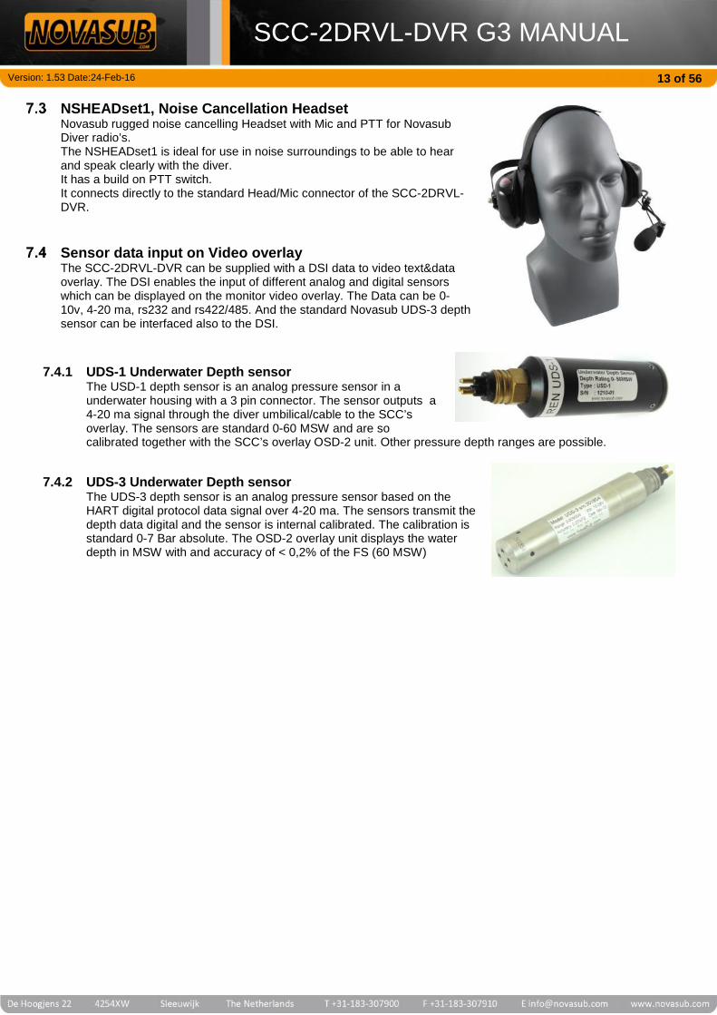
NSHEADset1, Noise Cancellation HeadsetNovasub rugged noise cancelling Headset with Mic and PTT for NovasubDiver radio’s.The NSHEADset1 is ideal for use in noise surroundings to be able to hearand speak clearly with the diver.It has a build on PTT switch.It connects directly to the standard Head/Mic connector of the SCC-2DRVL-DVR.
Sensor data input on Video overlayThe SCC-2DRVL-DVR can be supplied with a DSI data to video text&dataoverlay. The DSI enables the input of different analog and digital sensorswhich can be displayed on the monitor video overlay. The Data can be 0-10v, 4-20 ma, rs232 and rs422/485. And the standard Novasub UDS-3 depthsensor can be interfaced also to the DSI.
7.4.1 UDS-1 Underwater Depth sensorThe USD-1 depth sensor is an analog pressure sensor in aunderwater housing with a 3 pin connector. The sensor outputs a4-20 ma signal through the diver umbilical/cable to the SCC’soverlay. The sensors are standard 0-60 MSW and are socalibrated together with the SCC’s overlay OSD-2 unit. Other pressure depth ranges are possible.
7.4.2 UDS-3 Underwater Depth sensorThe UDS-3 depth sensor is an analog pressure sensor based on theHART digital protocol data signal over 4-20 ma. The sensors transmit thedepth data digital and the sensor is internal calibrated. The calibration isstandard 0-7 Bar absolute. The OSD-2 overlay unit displays the waterdepth in MSW with and accuracy of < 0,2% of the FS (60 MSW)

Version: 1.53 Date:24-Feb-16
SCC-2DRVL-DVR G3 MANUAL14 of 56
Thickness Gauge (T)The data of a Ultrasoon thickness gauge can be displayed on the videooverlay. Standard the OSD-2 is configured for the Tritex Multigauge 3000.
CP probe (CP)The OSD-2 has a built in 0-2000 mV input which can be used with a underwater Proximity Probe to measure thecathodic potentials.
Third party camera connectionThe SCC-2DRVL-DVR is fully built to accept the standard Novasub video cameras.However any brand of analog video camera can be connected to the SCC-2DRVL-DVR.The standard voltage output to the camera connection is 32 vdc.This can be configured to a lower voltage by Seascape at its factory.On new orders please specify required voltage range.Standard range are 12 vdc, 15 vdc and 24 vdc.
Low voltage power supplyThe SCC can also be fitted with an extra external power supply connection of 12-36 vdc.The SCC can then be powered with 110 /230 vac or 12-36 vdc.

Version: 1.53 Date:24-Feb-16
SCC-2DRVL-DVR G3 MANUAL15 of 56
8 General FunctionsThe SCC-2DRVL-DVR has the full function control from the Keypad, Keyboard and optional Mouse.
Main PowerThe Main power switches on and off the complete unit.When the external IEC plug is inserted on the top left of the case the internal battery will be automatically charged. Thesystem can be powered with 100 – 240 vac 50/60 Hz and requires 150 watts.The Charge level LED’s will indicate that the system is being charged and the status of charge. Charging time for a fullydischarged system will take approx. 10 -12 hrs.When system is fully charged the batteries are automatically trickle charged to maintain full capacity.The Main power does not need to be switched on to the charge the system.
Charge level Led indicating the level of the battery (Solid) when there is external power(100-220 vac) connected and charging the internal battery (UPS)• Bulk charging • Trickle charge •Maintenance charge
Video&AudioOut
DVR USB DVR LAN
Main PowerSwitch
Keypad
Keyboard Keyboard USB
HDMI Out
Comms Mode
Light Dimmer
Volume Diver
Volume Tender
Cross-Talk
PTT
SpeakerSwitch
Speaker
Volume Ext.Speaker
Mic/Headset
Powersupply
Diver 1 cableconnector &comms bananasockets
Diver 2 cableconnector &comms bananasockets
Ext.SpeakerConnector

Version: 1.53 Date:24-Feb-16
SCC-2DRVL-DVR G3 MANUAL16 of 56
Diver Communications
The diver audio is standard set for a 2 wire communications (simplex).The divers can only speak to each other when the surface operator pushes the cross-talk switch to the desired direction.
The SCC-2DRVL-DVR can also be set for 4 wire communication (duplex)The divers have an open 2 way communications with each other without any selection from the surface. The surface willhear both divers and can talk to the desired diver by pressing the corresponding PTT. Also can the comms be set forFull duplex. The there is a full open communication (conference) between the divers and surface.
8.2.1 2 wire comms configurationThe SCC-2DRVL-DVR is standard fitted with a 10 pin multipin connector.The audio comms for 2 wire comms is connected to the diver umbilical via the multipin connector (pins H,J) or viathe yellow Banana sockets
8.2.2 4 wire comms configurationThe SCC-2DRVL-DVR can be fitted with a 10 pins multipin connector and a selection comms mode switch. Thisallows the use of a 4 wire comms system and still be able also to use the system as a 2 wire system.
The 4 wire configurations has 3 user modes:2S - 2 or 4 wire simplex4HD- 4 wire Half duplex surface to diver, full duplex diver to diver4FD - 4 wire Full duplex, surface and divers full duplex without any PTT
8.2.3 2/4S - 2 wire simplexThis mode is the same as the standard comms when using 2 wire. This works with either 2 or 4 wires comms cableconfiguration. The diver will always be heard at the surface and the Tender needs to push the PTT switch to talk tothe diver. The divers can only speak to each other when the Tender uses the Cross to Talk switch from diver 1 todiver 2 and vice versa.
8.2.4 4HD – 4 wire Half DuplexThis mode uses a 4 wire comms cable configuration. In this mode the divers can speak with each other without anycontrol from the Tender. The Tender will hear both.The Tender needs to push the PTT button to speak to the divers.
8.2.5 4FD- 4 wire Full DuplexThis mode allows to have a full open communication between divers and Tender to divers without using the PTTbuttons. Like a conference call.

Version: 1.53 Date:24-Feb-16
SCC-2DRVL-DVR G3 MANUAL17 of 56
8.2.6 Comms Volume controlEach diver has a Tender and Diver volume control.The Volume Diver is the volume control of what the diver hearsThe Volume Tender is the volume control of what the tender hears
8.2.7 Internal MICOn the panel between the Volume Tender control, the internal MICis positioned. It is not needed to place your mouth close the theMic. Normal arm length distance is sufficient to pick-up the Tenderspeaking volume.
8.2.8 Push To Talk (PTT)The button per diver to press when the Tender want’s to speak tothe diver.
8.2.9 Cross-TalkThe cross talk switch can be used to have Diver 1 speak to Diver 2 in a 2 wire comms configuration. When thetoggle switch is pushed direction Diver 2, then Diver 1 can speak to Diver 2. If the toggle switch is pushed towardsDiver 1, then Diver 2 can speak to Diver 1.
Internal SpeakerThe Internal Speaker can be switched off with the rocker switch Speaker. This can be used when operating with theMic/Headset or only with the external speakers
External Speaker
The SCC has a built in 10 watt amplifier to which an external 4-8 ohm (10-30w) speaker can be connected. The externalspeaker has its own volume control.All conversation, divers and tender are heard on the ext. speaker.
Bananaconnection orbare wire
Version: 1.53 Date:24-Feb-16
SCC-2DRVL-DVR G3 MANUAL18 of 56
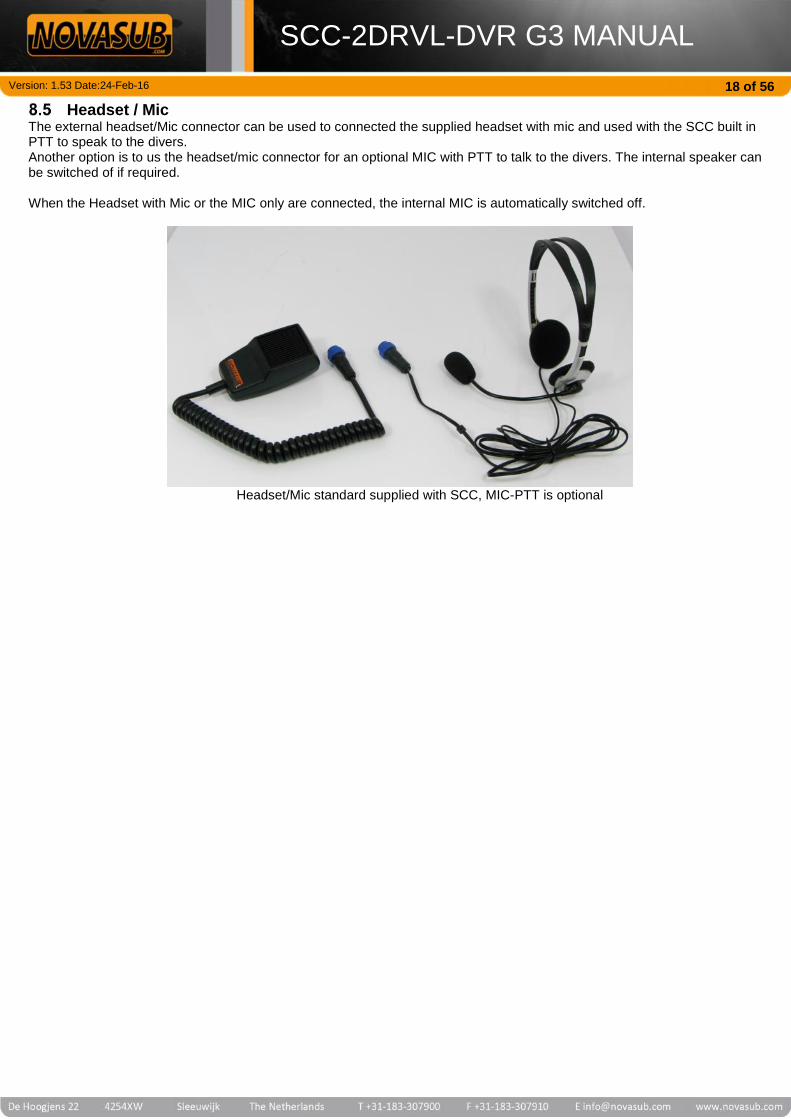
Headset / MicThe external headset/Mic connector can be used to connected the supplied headset with mic and used with the SCC built inPTT to speak to the divers.Another option is to us the headset/mic connector for an optional MIC with PTT to talk to the divers. The internal speaker canbe switched of if required.
When the Headset with Mic or the MIC only are connected, the internal MIC is automatically switched off.
Headset/Mic standard supplied with SCC, MIC-PTT is optional

Version: 1.53 Date:24-Feb-16
SCC-2DRVL-DVR G3 MANUAL19 of 56
Keypad control
Keypad for NSDVR2-2, 2 channel recording
Keypad for 2 channel system. The keypad is for direct recording and snapshot function. With the arrows, OK, Menu and escyou can scroll through the complete menu for all settings. The CAM and Light buttons are used to switch on the camera andlight and control the light intensity in steps of 10%. The yellow LED on the CAM and LIGHT lit-up when a camera and light isswitched on. Each key has a unique function or a multiple function
MENU Enters in the Main menu of the NSDVR2 recorder
VIEW Scroll between the different views; PAPV, PAPH and PIP
ESC Return to previous or cancelUp Up in Main menu’s and value higher in settingsRight To the right in Main menu’s and to next settings in setting menu’sDown Down in Main menu’s and value lower in settingsLeft To the left in Main menu’s and to previous settings in setting menu’s
OK ConfirmFR In playback fast reverse, press multiple times for 4x and 8x speedPLAY Enters directly in playback menu
STOP Stop Playback
FF In playback fast forward, press long to activate. In Search/Backup use to select files in list
LIGHT + Switches the light on (100% at start up) and increases intensity in 10 steps
LIGHT - Switches the light OFF (press long) and decreases intensity in 10 steps
SNAP Takes a snapshot of the selected channel
CAM Switches the camera ON and OFF
REC Start and stops recording per channel
1 (2,3,4)
Channel selection, when the channel is selected the Green LED is on and has the followingoptions:
You can control the camera and light of this channel You can access the video text overlay of this channel When you press SNAP, the snapshot will be taken of this channel In PIP and Quad view you will select this channel as single view or main view
LED indications
Batterystatus
All Novasub SCC and SCU units have a build in battery backup which operates as an UPS(uninterrupted power supply). The batteries are automatically charged when external power issupplied. The LED are solid when external power is present and blinking when operating onbattery.LED solid indication charging• Bulk charging • Trickle charge •Maintenance chargeLED blinking indication operating on battery• Batt. LOW • Batt. half full • Batt. FULL
Channel Green led: this channel is selectedCAM yellow led: Camera is switched on of this channelLight yellow led: Light is switched on of this channel
REC LedThe red REC LED is on when recording this channel
Version: 1.53 Date:24-Feb-16
SCC-2DRVL-DVR G3 MANUAL20 of 56
Mouse function descriptionsWhen a USB mouse is connected to the DVR USB you can access the menu fully with the mouse using the Left and Rightbuttons.
Right Mouse button functions: Opens Main menu Esc or return to previous menu Select file in playback or backup search list Hide playback menu bar
Left Mouse button functions: Select and operate

Version: 1.53 Date:24-Feb-16
SCC-2DRVL-DVR G3 MANUAL21 of 56
9 Main OperationsThis chapter describes the main basic operations to be able to start the system, have a live camera view, control the light andrecord the video. Also we explain how to playback and backup your files.
System startupConnect the main cable with the camera and light, connect the power supply. Make sure that the actual camera and lightare connected at the other end of the cable.Follow next steps to quick start the system and start recording.
ViewThe view button is to select the different view modes of the 1 or 2 channels. Scroll between the different views; PAPV,PAPH and PIP.
NOTE! To go back to single channel view from PIP, press first VIEW to be in PAPmode. Then press Channel button 1 or 2 to see the channel in single view
9.2.1 PAPPAP stands for Picture and Picture, and shows only 2 channels. PAPH shows the 2 channels vertical one abovethe other. PAPV shows the 2 channels horizontal side by side.Date&Time will only show on the Top or left channel in live view. It will be recorded in all other channels, while notvisible in live view.
Plug in Mainpower cables
Plug in external power supply 100-240 vac. The system willautomatically start charging the internal battery. Even withthe main power switch off.
Connect cable Connect cable with camera and light
Switch Mainpower on
If external 100-220 Vac power is supplied the Charge Levelwill indicate that the battery is charging and the status of thecharge by color. (solid LED)When NO external power is supplied the Battery Level isindicated by blinking LED and indicates the battery statusby color. Power / Battery status
Switch on theCamera andlight
Select the channel to control. Green LED is ON.Press camera button, the CAM yellow LED switches onPress light + to switch light on, the green LED indicates thatthe light is powered. Increase and decrease light intensitywith + and -. Press and hold + to switch on the Max. lightIntensity. Press and Hold – to switch the light off. Select CH Light camera
Recording Press Rec to start recording, Red LED is onPress Rec to stop recording, Red LED is off Start/Stop Recording
SnapshotTake a picture of the video image, select the channel andpress SNAP Button. The snapshots are stored on the harddisk. Take a Snapshot
View settings Press view to scroll between different views.

Version: 1.53 Date:24-Feb-16
SCC-2DRVL-DVR G3 MANUAL22 of 56
9.2.2 PIPPIP stands for Picture in Picture. You activate here the PIP mode.PIP is a small view of another channel on top of the main view.PIP has the option of ¼ or 1/9 size. You can freely move the PIP view over the main view using the keypad controlor the mouse.The select the main view channel press one of the channel buttons, to select the pip view channel press the left orright keypad button to scroll through the other channels
9.2.2.1 PIP window view controlTo access the PIP view, you can use the VIEW button by pressing multiple times to scroll to the PIP view.Or use the main menu and select PIP, either using the mouse or the arrow buttons.
o To resize and position the PIP window with the keypad:Press and hold the VIEW button for a several seconds, release and press again to change from 1/9 to 1/4and again back to 1/9. Use the arrow keys to position de PIP window. If the PIP window is positioned inone of the corners you will need to press multiple times the arrow key before the window starts moving.
o To resize and position the PIP window with the Mouse:Click the right button to show the Main Menu and select PIP.In PIP mode, right click mouse button and you can select the PIP size ¼ or 1/9To move the PIP , click and hold with the left mouse button and drag the PIP window to the desiredposition.
o To exit PIP view with keypad:Select with view the QUAD or PAP view. In these views you can press the Channel button to show thischannel only.
o To exit the PIP view with Mouse:Press right mouse button and select Exit.
PIP 1/9 size PIP ¼ size

Version: 1.53 Date:24-Feb-16
SCC-2DRVL-DVR G3 MANUAL23 of 56
Video Text OverlayThe internal overlay per channel is based on 4x lines with text, date &time and channel name-text. The 4x overlay linescan be added from the MenuSetupVideo and the keyboard.The overlay text is white and can be highlighted with a grey background in light video conditions.Each overlay line corresponds to a Function Key on the keyboard.F1 = Free text line with 36 charactersF2 = Free text line with 36 charactersF3 = Channel name and Free text line, total 36 charactersF4 = Date, Time & Data line (Diver depth, Diver Time, and more)
F1 and F2Free Text
Press F1 or F2 and type text or remove move text withBack Space.
F1 and F2Hiding/Showing Press CTRL-F1 or CTRL-F2 to Show and Hide overlay
F3Channel Name
Press F3 to move Channel name and add or remove freetext after channel name.
F4Date,Time & Data Press F4 to move the Date, Time & Data overlay
Moving OverlayApplies for all
Move the position of the text line with the arrow keys of thekeyboard.
OverlayBackground
The add or remove dark background behind overlay, go toMain Menu MenuSetupSetup. Scroll with Left orright arrow key to Background and select or deselect withOK Dark Background is on
F3 Channel NameChanging
To change the channel name, go to:Main Menu MenuSetupVideoScroll to name and change here the name, use the virtualkeyboard.
F3 Channel name& F4 date & timeHiding / showing
To hide and show the Channel name an date & time, go to:Main Menu MenuSetupVideoScroll to Show name or Show time and select or deselectwith OK
Channel name is showing
Date & Time is showing

Version: 1.53 Date:24-Feb-16
SCC-2DRVL-DVR G3 MANUAL24 of 56
Camera and light controlThe camera and light are switched on from the keypad. The Camera has a button with LED and the Light has a buttonand LED. The light intensity can be controlled with the – and + keys.
9.4.1 Camera signalThe SCC has a built in auto tunable video line driver for each camera. This video line driver allows the use of videosignal over twisted pair or coax cable up to a maximum length of 600 m. Also the line driver can be set for coaxcable use.The Novasub cameras are available with video line driver for video signal over twisted pair and coax.The Novasub cameras set for Twisted Pair can also be used on Coaxial umbilical’s or cables.The power supply to the camera is standard 32 Vdc, if required the voltage can be set to 12, 15 or 24 Vdc. This is afactory setting.**Only on order of SCC-2DRVL-DVR.
9.4.1.1 Why use video transmission over Twisted pairNovasub has developed video transmission converters that makes it possible to transfer a video compositesignal over a standard twisted pair cable. The latest converters are Auto tuneable for cable length up to 600m. All standard Novasub camera and topside control units have these video transmission converters built in.The cameras have a composite video to twisted pair signal transmitter, and the topside units have a twistedpair signal to composite video receiver.
All Novasub cables and umbilical’s, are standard fitted with screened twisted pairs (STP). These STP are usedfor all possible data/audio and video transmission.Novasub does not use Coax for video signal transmission. The reason is the mainly weak and interferencesensitive Coax cable.
NOVASUB umbilical and cable uses video signal transmission over shielded twisted-pairs (STP).The advantages of twisted-pair are; more reliable video transmission through less interference( electromechanical- or radio frequency
interference) higher movability through higher flexibility STP is a stronger cable then coax higher flexibility in applications, twisted-pair cabling is the standard in data transfer worldwide easier to install/repair/handle
9.4.2 Light controllerThe SCC-2DRVL-DVR is standard fitted with a LED light controller that matches the Novasub LUX3 and LUX6lights. The LED controller regulates the Ampere from 0-1,6 A at 32 vdc.An Halogen light bulb up to max. 25/30 watts can also be controlled directly from the LED-controller.Also other brands of LED light can be controlled, however they need to be internal protected against a max.of 1,6Amp. Current and a 32 Vdc voltage.If required the max. output Ampere can be set to a lower and higher value. This is a factory setting.
Switch on theCamera
Select the Channel, Green LED is ONPress camera button, the CAM yellow LED switches on
Switch on theLight
Select the Channel, Green LED is ONPress light + to switch light on, the green LED indicates thatthe light is powered. Press and hold + to switch on the Max.light Intensity. Press and Hold – to switch the light off.
Light IntensityControl
Increase and decrease light intensity with + and -.Or use the Yellow Intensity Light rotation potentiometer.

Version: 1.53 Date:24-Feb-16
SCC-2DRVL-DVR G3 MANUAL25 of 56
RecordingThe SCC-2DRVL-DVR has a quick start recording button per channel. Once clicked it will start recording immediately.If in the DVR Setup menu the status is selected, then a small rec Icon will appear on the monitor indicating that video isbeing recorded. Also de red LED on the button will lit-up when recording.The files are automatically recorded in max. files size of 260 Mb each. During recording the NSDVR2 will automaticallymake a new file. The time per file depends on the video quality set in the setup-record menu.
SnapshotThe DVR has a snapshot function. The snapshot will only be made of the selected channel. The snapshot button, whenpressed, makes an image file of the video image seen at that moment. The snapshot includes the text overlay as seenin the preview an recording.When the snapshot button is pressed a black status indication will appear, “Snapshot OK”The snapshots are stored on the Hard Disk in a JPG format with the same resolution as the recording resolution.The Snapshot function automatically generates a file name.The file name is based on the channel number, date and time; chn120140620150802chn1 2014-06-20 15:08:02Channel 1 date Time
The snapshot files cannot be viewed back with the SCC-1VL-DVR. You can only backup them to a memory stick andview on a PC. See Chapter 9.10
Recording Press Rec to start recording, Red LED is onPress Rec to stop recording, Red LED is off
SnapshotSelect the Channel, Green LED is ONTake a picture of the video image, select the channel andpress SNAP Button. The snapshots are stored on the harddisk.

Version: 1.53 Date:24-Feb-16
SCC-2DRVL-DVR G3 MANUAL26 of 56
PlaybackThe video files recorded can be played back using the DVR player.To quickly access the Play menu, press the Play button on the keypad.
Playbackrecorded files
Press Play button to access Playback search menu.Use the Scroll arrows to go through the menu’s
Play menu Scroll
Press OK to select All channels or select channel 1,2,3 or 4, and scrollwith right and left arrows key to next item in menu. Select channel. SelectType-Manual, Select the date range you want to playback and scroll toSearch to open Search result list. Scroll down to file you want to play andpress OK
The Duration is automatic the current day from 00:00 to present time.
The search result shows 8 files per page. The newest file on top of thelist. You can scroll to the next page with Next.
The index line shows, the channel, start date &time, and file size.
9.7.1 Playback status BarDuring playback a status bar appears which can be used to scroll throughvideo file. To Hide status bar press right-mouse button, or CTRL-H onkeyboard.You can also use the Mouse for quick playback control
Stop PausePlay
Step Slow FF FF FR PreviousFile
NextFile
MuteSound
ImageSettings
ElecZoom
PlaySpeed
PlayTime
Total recordedtime
Scroll Bar

Version: 1.53 Date:24-Feb-16
SCC-2DRVL-DVR G3 MANUAL27 of 56
9.7.2 Keypad & Keyboard control during playbackYou can scroll through status bar Icons with the left and right arrow keys, press OK to select.
Fast forwardPress and Hold the Fast-Forward button for 2 seconds,repeat for each speed step. You can fast forward in 3speeds, 2x, 4x and 8x
Fast Reverse Press Fast- Reverse, repeat for each speed step. You canfast rteverse in 3 speeds, 2x, 4x and 8x
Stop Press Stop to stop the playback
Hide/Showstatus
Press CTRL-H on the keyboard to Hide or Show the statusbar
9.7.3 Mouse control during playbackYou can use the mouse during playback.Use the slider to scroll quickly through the video files. Press any of the icons for the corresponding function.With the right mouse button you can Hide or Show the status bar.
Audio to SpeakerWhen a video file with audio is played back the audio will be heard on internal the speaker. This will be automatically.There is no volume control for the audio playback.
Backup/Copy filesUse the same player to select and backup your files to an external USB storage device.
Search the files as described in playback (9.7) and select the files youwant to backup using the FF keypad button when the file is greyhighlighted or use the right mouse button to select. When the files isselected a “v” appears on the file line. You can select 8 files at thetime. After selection of files click or select Backup and press OKIn the next window select avi file and press OK. A backup progressindicator will appear. Depending on the amount of files and the size itcan take some minutes to complete the backup.
Copy files(backup)
Press Play button to access Playback search menu.Use the Scroll arrows to go through the menu’s
Play menu Scroll Select

Version: 1.53 Date:24-Feb-16
SCC-2DRVL-DVR G3 MANUAL28 of 56
Snapshot Backup/Copy filesThe snapshots are backup using the Snapshot Backup command in de Main Menu.The snapshot files cannot be playback on the DVR, they need to be stored on an external storage device and viewed ona PC.
Snapshotbackup Press Menu and scroll to Snapshot Backup, press OK.
Main Menu Scroll
Select Snapshot backup to copy the snapshots stored on the hard diskto the USB storage.Select the date of which you want to select the stored snapshots.Press Search to select manual the Snapshots, or press directlybackup to store all snapshots of that date selection.In Search a drop list appears with the last snapshot on top.You can select a grey highlighted snapshot with the FF button, or withthe mouse press right button. When the files is selected a “v” appearson the file line. You can select 8 files at the time.Only 8 snapshots are shown per page, you can scroll to the next pagewith Next.

Version: 1.53 Date:24-Feb-16
SCC-2DRVL-DVR G3 MANUAL29 of 56
10 Internal DVRP2 Menu settingsThe keypad which is connected to the DVRP2 DVR control unit has a hidden Menu for overlay and light settings. The overlaysettings are used to hide and show the overlay, and to set certain hardware data information to be displayed on the overlay.The lights settings are used to select the max. light control output per channel.
Main Menu DVR2The menu has the following structure. This menu structure is based on DVRP2 v0.25
OK
Firmware UpdateReset SettingsChannel Offset
InfoIntern Overlay
Maintenance menu
Channel 2 settingsChannel 1 settings
MaintenanceMain Menu
Set Light TypeShow DDG divetime
Show DDG depthShow DSI Depth
Channel 1 Settings
OK OFF >ON<
OK Device InfoDVRP2 (vers ion)
OK 00
OK Reset Setings
OK
>OFF< ON
>OFF< ON
>OFF< DSI DDG
>LUX6< LUX3
MENU
Select with
Select with
CH1 screen Press&Hold MENU3 seconds
ESC MENU
Scroll with
Scroll with
Scroll with
To scroll through Menu use up and down Arrows to scroll up and down in menu items, Ok and left and right arrows to selectand Menu button to go back one step. The selected setting is indicated between >…< arrow symbolsPress ESC button to leave the Main Menu.The settings for Channel 2, 3 and 4 are the same as channel 1

Version: 1.53 Date:24-Feb-16
SCC-2DRVL-DVR G3 MANUAL30 of 56
Menu descriptionMake sure that you have CH1 selected to be able to go into the Main Menu
10.2.1 Main Menu accessThis is the General Menu of the DVRP2controls from the keypad Membrane to theDVR recorded
To access the hidden Menu, press andHold for a 3 seconds the MENU buttonof the keypad membrane. And release.
The overlay will show a the MAINMENU.
10.2.2 Maintenance MenuGeneral settings of the DVRP2 and DVRoverlay
Press OK to enter Maintenance MenuOr scroll down with down arrow key togo to Channel settings
10.2.3 Intern OverlaySelect here to switch on and off Internaloverlay text
Press OK to enter Intern Overlay ONand Off settings.Use left and right arrow keys to selectsetting
10.2.4 InfoShows the firmware version of the DVRP2
From Maintenance Menu scroll down toInfo and press OK.This shows the version of the DVRP2firmware.
10.2.5 Channel OffsetIs used only to set the units channelnumber in case of use of more than oneSCC/SCU-xx-DVR in the NovaBus network
From Maintenance Menu scroll down toChannel Offset and press OK.Scroll down or up to select channeloffset.
10.2.6 Reset settingsResets DVRP2 Menu settings to factorydefault
From Maintenance Menu scroll down toReset Settings and press OK. Press OKagain to reset to factory default settings
10.2.7 Firmware UpdateThis is used to update the DVRP2firmware.Special hardware and software is required.Normally this is factory preformed
From Maintenance Menu scroll down toFirmware Update and press OK to startFirmware update
10.2.8 Channel settings (1,2,3 or4)
Each channel has settings for data inputfrom the DDG (Novasub digital depthGauge) and light output control settings
From Main Menu scroll down to Channelsettings and press OK
10.2.9 Show DSI DepthThe DSI depth is the depth input from theDSI pcb board installed in the SCU/SCUunit. This board has an analog input HARTand 4- 20 ma ,which is used to convert thedepth sensor signal to the video overlay
From Channel x Settings scroll down toShow DSI depth and press OKSelect ON if you have a pressure sensorconnected to the DSI PCB board analoginput.
10.2.10 Show DDG DepthThis shows the depth from the DDG, digitaldepth gauge, either through the rs232 portof the DSI or directly from DDG connectedto the NovaBus input of the SCC/SCU.
From Channel x Settings scroll down toShow DDG depth and press OKSelect DSI for DDG connected withrs232 port to DSI. Select DDG for DDGconnected to NovaBus
10.2.11 Show DDG timeWhen the DDG is selected in show DDGdepth, then you are able to show the
From Channel x Settings scroll down toShow DDG divetime and press OKSelect ON to show on overlay

Version: 1.53 Date:24-Feb-16
SCC-2DRVL-DVR G3 MANUAL31 of 56
Divetime on the overlay which is shownduring a logged dive in the DDG
10.2.12 Set light TypeHere you can select the control output forour standard two LED lights, the LUX3 andLUX6.If you set to LUX3, then full control of thelight will output 0,8 A (LUX3 maximum), ifyou set to LUX6 than the output will be 1,7A (LUX6 maximum)
From Channel x Settings scroll down toSet Light type and press OK.Select LUX3 or LUX6.

Version: 1.53 Date:24-Feb-16
SCC-2DRVL-DVR G3 MANUAL32 of 56
11 DVR Main MenuThe follow chapter describes the complete NSDVR2 menu.The NSDVR2 has a menu for all settings and control and backup.The main menu is opened when you press MENU or use the right mouse button.The first time after startup you will access a login menu, press 2x and OK.If you have set different users and levels you can select another user in this menu.The Main Menu has the following selections:
1 Channel (1 CH)Here you can select after pressing Menu which channel to see as main.Quick access is by pressing the Channel button on the keypad. When the channel is selected the green LED will goon.
PIPPIP stands for Picture in Picture. You activate here the PIP mode.PIP is a small view of another channel on top of the main view.PIP has the option of ¼ or 1/9 size. You can freely move the PIP view over the main view using the keypad control orthe mouse.The select the main view channel press one of the channel buttons, to select the pip view channel press the left orright keypad button to scroll through the other channels
11.2.1 PIP window view controlTo access the PIP view, you can use the VIEW button by pressing multiple times to scroll to the PIP view.Or use the main menu and select PIP, either using the mouse or the arrow buttons.
o To resize and position the PIP window with the keypad:Press and hold the VIEW button for a several seconds, release and press again to change from 1/9 to 1/4and again back to 1/9. Use the arrow keys to position de PIP window. If the PIP window is positioned inone of the corners you will need to press multiple times the arrow key before the window starts moving.
o To resize and position the PIP window with the Mouse:Click the right button to show the Main Menu and select PIP.In PIP mode, right click mouse button and you can select the PIP size ¼ or 1/9To move the PIP , click and hold with the left mouse button and drag the PIP window to the desiredposition.
o To exit PIP view with keypad:Select with view the QUAD or PAP view. In these views you can press the Channel button to show thischannel only.
o To exit the PIP view with Mouse:Press right mouse button and select Exit.
PAPHPAP stands for Picture and Picture, PAPH shows the 2 channels vertical one above the other.
PAPVPAPV shows to channel horizontal side by side.
1CH 1 channel view, select channelPIP Picture in Picture viewPAPH Picture and picture view, horizontalPAPV Picture and picture view, verticalElec Zoom Zoom area (only with Mouse)Spot Select channel for spot view (not
applicable for SCC units)Snapshotbackup
Search and select snapshots tobackup to USB device
Playback Opens playback search and selectRecord Start and stop channel to recordMute Mute is no sound to audio output and
Sound is audio active to audio autputMenu Opens sub menu’s

Version: 1.53 Date:24-Feb-16
SCC-2DRVL-DVR G3 MANUAL33 of 56
Elec ZoomYou can zoom with the mouse into the video. Drag with the mouse left button a rectangular of the area you want tozoom. Press right mouse button to cancel.
SpotNote: Spot is not applicable for the SCC-2DRVL-DVR
Snapshot backupSelect Snapshot backup to copy the snapshots stored on the hard diskto the USB storage.Select the date of which you want to select the stored snapshots.Press Search to select manual the Snapshots, or press directlybackup to store all snapshots of that date selection.In Search a drop list appears with the last snapshot on top.You can select a grey highlighted snapshot with the FF button, or withthe mouse press right button. When the files is selected a “v” appearson the file line. You can select 8 files at the time.Only 8 snapshots are shown per page, you can scroll to the next pagewith Next.
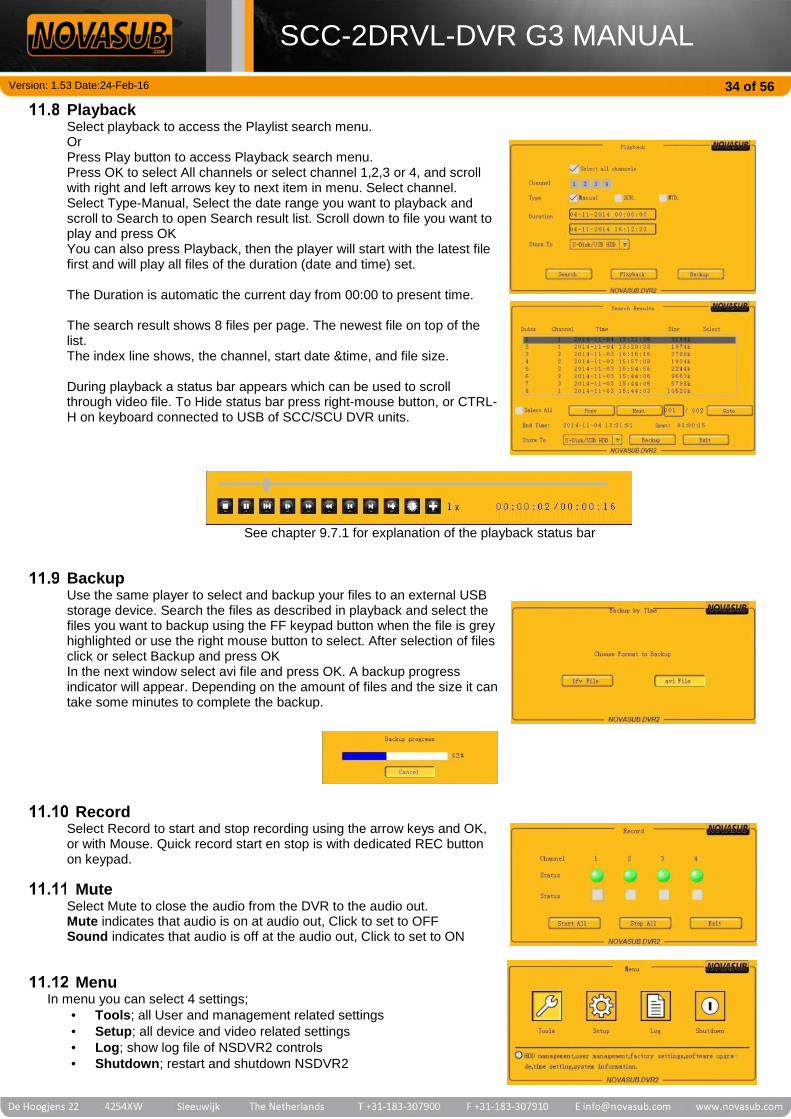
Version: 1.53 Date:24-Feb-16
SCC-2DRVL-DVR G3 MANUAL34 of 56
PlaybackSelect playback to access the Playlist search menu.OrPress Play button to access Playback search menu.Press OK to select All channels or select channel 1,2,3 or 4, and scrollwith right and left arrows key to next item in menu. Select channel.Select Type-Manual, Select the date range you want to playback andscroll to Search to open Search result list. Scroll down to file you want toplay and press OKYou can also press Playback, then the player will start with the latest filefirst and will play all files of the duration (date and time) set.
The Duration is automatic the current day from 00:00 to present time.
The search result shows 8 files per page. The newest file on top of thelist.The index line shows, the channel, start date &time, and file size.
During playback a status bar appears which can be used to scrollthrough video file. To Hide status bar press right-mouse button, or CTRL-H on keyboard connected to USB of SCC/SCU DVR units.
See chapter 9.7.1 for explanation of the playback status bar
BackupUse the same player to select and backup your files to an external USBstorage device. Search the files as described in playback and select thefiles you want to backup using the FF keypad button when the file is greyhighlighted or use the right mouse button to select. After selection of filesclick or select Backup and press OKIn the next window select avi file and press OK. A backup progressindicator will appear. Depending on the amount of files and the size it cantake some minutes to complete the backup.
RecordSelect Record to start and stop recording using the arrow keys and OK,or with Mouse. Quick record start en stop is with dedicated REC buttonon keypad.
MuteSelect Mute to close the audio from the DVR to the audio out.Mute indicates that audio is on at audio out, Click to set to OFFSound indicates that audio is off at the audio out, Click to set to ON
MenuIn menu you can select 4 settings;
Tools; all User and management related settings Setup; all device and video related settings Log; show log file of NSDVR2 controls Shutdown; restart and shutdown NSDVR2

Version: 1.53 Date:24-Feb-16
SCC-2DRVL-DVR G3 MANUAL35 of 56
11.12.1 Value editing controlIn different menu’s there are values which can be edited. The value’s where you can type and edit/add text and numbersare based on virtual keyboards. The virtual keyboard for numbers automatically pop-ups when you edit a value at theposition.
Virtual keyboard pop-up
11.12.1.1 How to add or edit a value with the keypad: Go to the position with the arrow keys left and right. Press OK, the virtual keyboard will pop-up Select the value by scrolling with the arrow keys and press OK
To change the type of virtual keyboard, press FF key for more than 2 seconds.You can scroll through 4 different keyboards
Use the backspace arrow to remove a value.
Press FF key longer than 2 seconds and the keyboard changes
The following virtual keyboards are available:
11.12.1.2 How to add or edit a value with the Mouse:With the mouse you can select a value with the left mouse button. To change the virtual keyboard click on the greybutton which appears when you are editing a value for the 5 different keyboards.Use the right mouse button to go back one level
Nummeric value
Letter value Capitol Letter value Special symbols
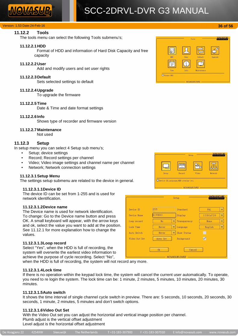
Version: 1.53 Date:24-Feb-16
SCC-2DRVL-DVR G3 MANUAL36 of 56
11.12.2 ToolsThe tools menu can select the following Tools submenu’s;
11.12.2.1 HDDFormat of HDD and information of Hard Disk Capacity and free
capacity
11.12.2.2 UserAdd and modify users and set user rights
11.12.2.3 DefaultSets selected settings to default
11.12.2.4 UpgradeTo upgrade the firmware
11.12.2.5 TimeDate & Time and date format settings
11.12.2.6 InfoShows type of recorder and firmware version
11.12.2.7 MaintenanceNot used
11.12.3 SetupIn setup menu you can select 4 Setup sub menu’s;
Setup; device settings Record; Record settings per channel Video; Video image settings and channel name per channel Network; Network connection settings
11.12.3.1 Setup MenuThe settings setup submenu are related to the device in general.
11.12.3.1.1Device IDThe device ID can be set from 1-255 and is used fornetwork identification.
11.12.3.1.2Device nameThe Device name is used for network identification.To change: Go to the Device name button and pressOK. A small keyboard will appear, with the arrow keysand ok, select the value you want to add at the position.See 11.12.1 for more explanation how to change thevalues.
11.12.3.1.3Loop recordSelect “Yes”, when the HDD is full of recording, thesystem will overwrite the earliest video information toachieve the purpose of cycle recording. Select “No”,when the HDD is full of recording, the system will not record any more.
11.12.3.1.4Lock timeIf there is no operation within the keypad lock time, the system will cancel the current user automatically. To operate,you need to re login the system. The lock time can be: 1 minute, 2 minutes, 5 minutes, 10 minutes, 20 minutes, 30minutes.
11.12.3.1.5Auto switchIt shows the time interval of single channel cycle switch in preview. There are: 5 seconds, 10 seconds, 20 seconds, 30seconds, 1 minute, 2 minutes, 5 minutes and don’t switch options.
11.12.3.1.6Video Out SetWith the Video Out set you can adjust the horizontal and vertical image position per channel.Plumb adjust is the vertical offset adjustmentLevel adjust is the horizontal offset adjustment
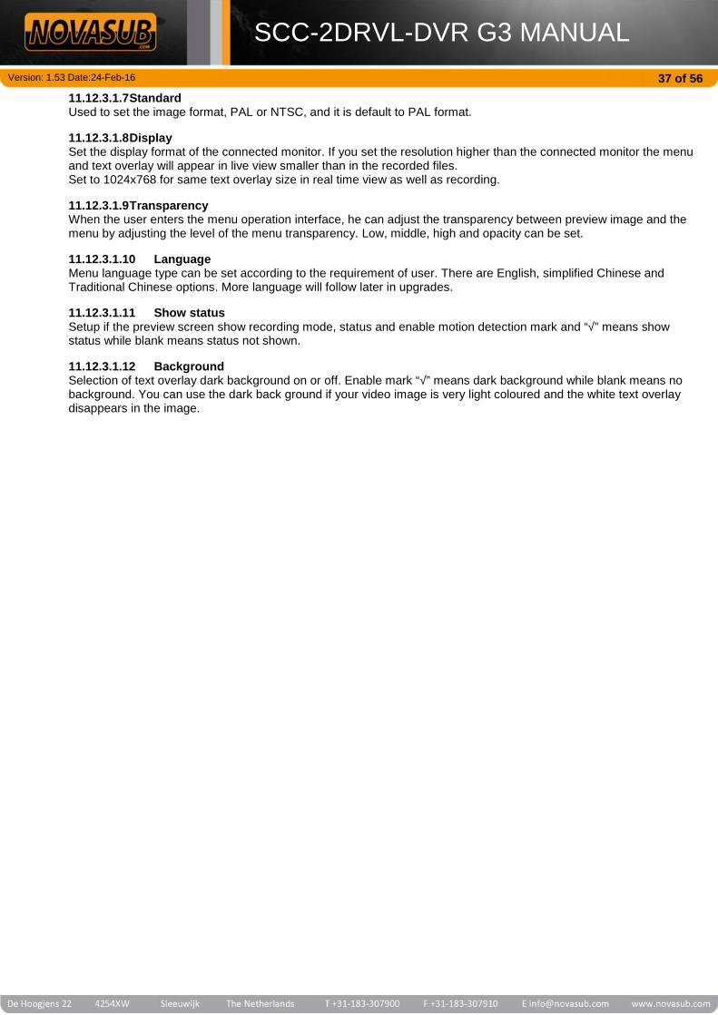
Version: 1.53 Date:24-Feb-16
SCC-2DRVL-DVR G3 MANUAL37 of 56
11.12.3.1.7StandardUsed to set the image format, PAL or NTSC, and it is default to PAL format.
11.12.3.1.8DisplaySet the display format of the connected monitor. If you set the resolution higher than the connected monitor the menuand text overlay will appear in live view smaller than in the recorded files.Set to 1024x768 for same text overlay size in real time view as well as recording.
11.12.3.1.9TransparencyWhen the user enters the menu operation interface, he can adjust the transparency between preview image and themenu by adjusting the level of the menu transparency. Low, middle, high and opacity can be set.
11.12.3.1.10 LanguageMenu language type can be set according to the requirement of user. There are English, simplified Chinese andTraditional Chinese options. More language will follow later in upgrades.
11.12.3.1.11 Show statusSetup if the preview screen show recording mode, status and enable motion detection mark and “√” means showstatus while blank means status not shown.
11.12.3.1.12 BackgroundSelection of text overlay dark background on or off. Enable mark “√” means dark background while blank means nobackground. You can use the dark back ground if your video image is very light coloured and the white text overlaydisappears in the image.
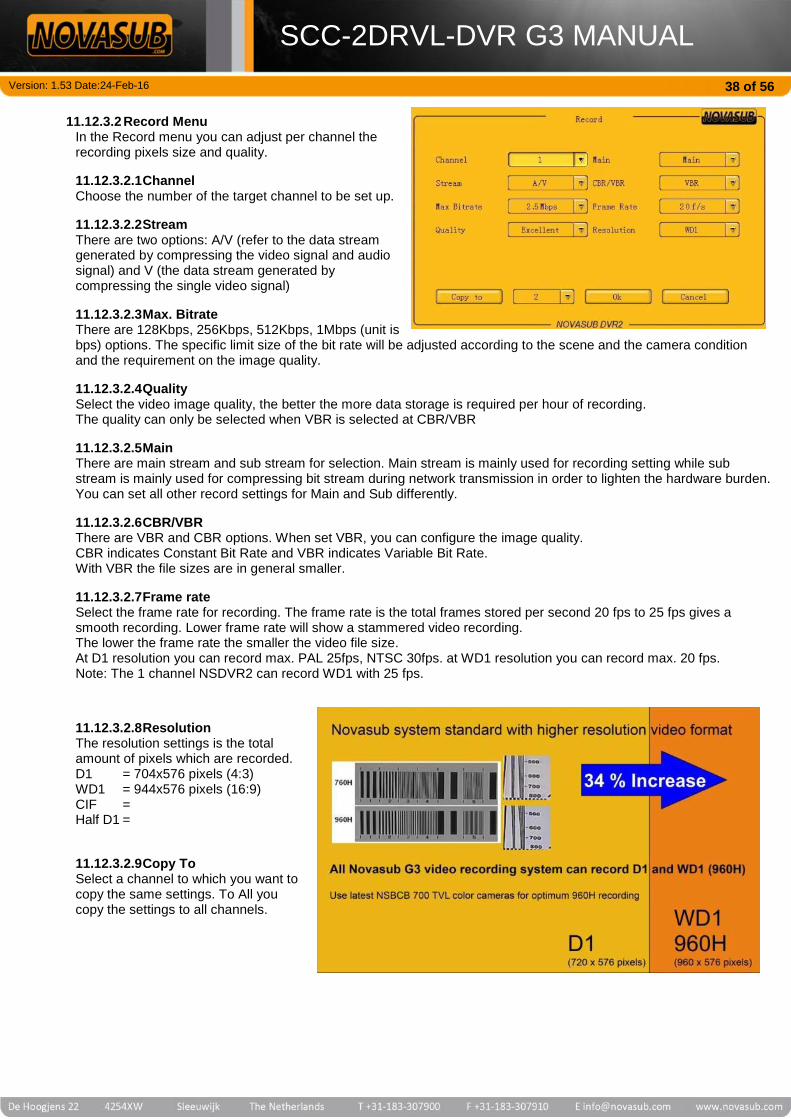
Version: 1.53 Date:24-Feb-16
SCC-2DRVL-DVR G3 MANUAL38 of 56
11.12.3.2 Record MenuIn the Record menu you can adjust per channel therecording pixels size and quality.
11.12.3.2.1ChannelChoose the number of the target channel to be set up.
11.12.3.2.2StreamThere are two options: A/V (refer to the data streamgenerated by compressing the video signal and audiosignal) and V (the data stream generated bycompressing the single video signal)
11.12.3.2.3Max. BitrateThere are 128Kbps, 256Kbps, 512Kbps, 1Mbps (unit isbps) options. The specific limit size of the bit rate will be adjusted according to the scene and the camera conditionand the requirement on the image quality.
11.12.3.2.4QualitySelect the video image quality, the better the more data storage is required per hour of recording.The quality can only be selected when VBR is selected at CBR/VBR
11.12.3.2.5MainThere are main stream and sub stream for selection. Main stream is mainly used for recording setting while substream is mainly used for compressing bit stream during network transmission in order to lighten the hardware burden.You can set all other record settings for Main and Sub differently.
11.12.3.2.6CBR/VBRThere are VBR and CBR options. When set VBR, you can configure the image quality.CBR indicates Constant Bit Rate and VBR indicates Variable Bit Rate.With VBR the file sizes are in general smaller.
11.12.3.2.7Frame rateSelect the frame rate for recording. The frame rate is the total frames stored per second 20 fps to 25 fps gives asmooth recording. Lower frame rate will show a stammered video recording.The lower the frame rate the smaller the video file size.At D1 resolution you can record max. PAL 25fps, NTSC 30fps. at WD1 resolution you can record max. 20 fps.Note: The 1 channel NSDVR2 can record WD1 with 25 fps.
11.12.3.2.8ResolutionThe resolution settings is the totalamount of pixels which are recorded.D1 = 704x576 pixels (4:3)WD1 = 944x576 pixels (16:9)CIF =Half D1 =
11.12.3.2.9Copy ToSelect a channel to which you want tocopy the same settings. To All youcopy the settings to all channels.

Version: 1.53 Date:24-Feb-16
SCC-2DRVL-DVR G3 MANUAL39 of 56
11.12.3.3 Video MenuVideo image settings per channel.
11.12.3.3.1ChannelSelect the channel for the settings
11.12.3.3.2NameThe channel name which is shown in the textoverlay F3. You can edit the text, see 11.12.1
11.12.3.3.3Show NameSelect if you want to show the name in thetext overlay. When you click on Position youcan place the text overlay on a differentposition. When you are in the live view andhave the channel selected you can also movethe positions after pressing F3 on thekeyboard, using the arrow keys of theKeyboard.
11.12.3.3.4ShowtimeSelect if you want to show the time in the text overlay. When you click on Position you can place the time overlay on adifferent position. When you are in the live view and have the channel selected you can also move the positions afterpressing F4 on the keyboard, using the arrow keys of the Keyboard.
11.12.3.3.5TimeSet the time for which the image settings below the time are applicable.
11.12.3.3.6BlindWith Blind you can set an area that will not be visible on the video image. Use the Mouse to set the area.Press menu to clear all blind areas.
11.12.3.3.7Standard (predefined image settings)The button standard has 4 predefined image settings. We advise Soft for best video image settings.
11.12.3.3.8Copy ToSelect a channel to which you want to copy the same settings. To All you copy the settings to all channels.
Note: Press OK to confirm each setting per channel.
11.12.3.4 Network MenuSettings for the network connection.
11.12.3.4.1LANYou can connect the NSDVR2 to a LAN Network. Enter here the requiredIP settings. By default the LAN is set to DHCP, the network to which theSCC will be connected determines the IP address
11.12.3.4.2PPPoEPPoE is Point-to-Point Protocol over Ethernet. Set the required settingshere.
11.12.3.4.3DDNSUse these settings for a Dynamic DNS server.
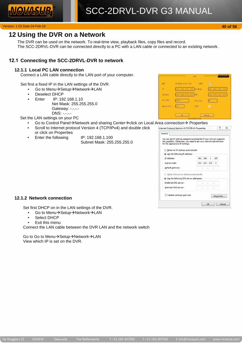
Version: 1.53 Date:24-Feb-16
SCC-2DRVL-DVR G3 MANUAL40 of 56
12 Using the DVR on a NetworkThe DVR can be used on the network. To real-time view, playback files, copy files and record.The SCC-2DRVL-DVR can be connected directly to a PC with a LAN cable or connected to an existing network.
Connecting the SCC-2DRVL-DVR to network
12.1.1 Local PC LAN connectionConnect a LAN cable directly to the LAN port of your computer.
Set first a fixed IP in the LAN settings of the DVR. Go to MenuSetupNetworkLAN Deselect DHCP Enter IP: 192.168.1.10
Net Mask: 255.255.255.0Gateway: -.-.-.-DNS: -.-.-.-
Set the LAN settings on your PC Go to Control PanelNetwork and sharing Centerclick on Local Area connection Properties Scroll to Internet protocol Version 4 (TCP/IPv4) and double click
or click on Properties Enter the following IP: 192.168.1.100
Subnet Mask: 255.255.255.0
12.1.2 Network connection
Set first DHCP on in the LAN settings of the DVR. Go to MenuSetupNetworkLAN Select DHCP Exit this menu
Connect the LAN cable between the DVR LAN and the network switch
Go to Go to MenuSetupNetworkLANView which IP is set on the DVR.

Version: 1.53 Date:24-Feb-16
SCC-2DRVL-DVR G3 MANUAL41 of 56
Connecting to DVRTo access the DVR over network you need to have Internet exploreron your PC.Start Internet Explorer and type the DVR IP address in the title bar.The following window will appear.Press the red arrow.
The first time you will be asked to install an ActiveX component.
Confirm the installation and also the use.
Press allowIf the following pop-up appears and install.
Press Install.If installation fails click on “Manual Installation package”
Download the file in a folder, extract and run.
Network DVR controlClose the Internet Explorer and open again.Type the IP address and press Red arrow key.

Version: 1.53 Date:24-Feb-16
SCC-2DRVL-DVR G3 MANUAL42 of 56
You will enter in the Main viewing page.
Click on a black window and then at the left select Channel 1 or 2.When they turn blue a connection is made and you will see the video image
Double click on a window to see it single channel.
12.3.1 Image controlOn window, click with right mouse button and you can select controls
OpenAudio: The audio on this channel can be listen to on the PC Snapshot: Take a snapshot of the image and is stored local on the PC
The Snapshots are stored in the folder which is set in the configure window.

Version: 1.53 Date:24-Feb-16
SCC-2DRVL-DVR G3 MANUAL43 of 56
Record: Start and stop record to local PCThe recorded file is stored in the folder which is set in the configure window.
PTZ Option: Pan, Tilt and zoom control, only for PTZ cameras OSD Option: Reposition the channel name text overlay Pic Adjust: adjust the image settings Envelop: mark an area to be blind Full screen: shows this channel image full screen
ConfigureAt the main window, at the right bottom you can select configure.In Configure-settings window you will see 5 tabs with different settings and control of the NSDVR2All settings changed here are stored in the NSDVR2, the same as you would change the settings in the NSDVR2 menu.
NOTE!The settings change here are stored in the NSDVR2 menu settings.Meaning that the changes made here are the same as making changesdirectly in the NSDVR2 Menu’s
12.4.1 Server parametersHere you can change the main and IP settings

Version: 1.53 Date:24-Feb-16
SCC-2DRVL-DVR G3 MANUAL44 of 56
12.4.2 Channel ParametersThis tab is for the recording, streaming and PTZ settings per channelSee chapter 11.12.3.2

Version: 1.53 Date:24-Feb-16
SCC-2DRVL-DVR G3 MANUAL45 of 56
12.4.3 Alarm parametersThese are alarm settings which you will not find in the regular DVR menu
12.4.4 User Info ParametersThe User info are the users you can add for login.
You can set per new user the rights

Version: 1.53 Date:24-Feb-16
SCC-2DRVL-DVR G3 MANUAL46 of 56
12.4.5 Other settingsHere you can start recording local on the NSDVR2 and set the remote recording folder.Also time can be set.

Version: 1.53 Date:24-Feb-16
SCC-2DRVL-DVR G3 MANUAL47 of 56
PlaybackYou can access the playback window by clicking on Playback, at the bottom right in the main window.Here you can playback and download recorded files from the NSDVR2
12.5.1 Search filesSelect the channel and date range to search for a recorded fileDouble click on the file in the list and it will be played.Double click on window to see single channel
12.5.2 Download filesYou can download to files from the search results to a local drive on your PC.Select one file or multiple files with Shift.Select Avi and click on File Download.Select the folder were to store the files
NOTE!If you are not allowed to download files to a folder on the PC, please checkyour User rights on the PC. Try to download to your Download folder onyour PC or to an external USB memory stick or hard drive plugged into yourPC

Version: 1.53 Date:24-Feb-16
SCC-2DRVL-DVR G3 MANUAL48 of 56
13 Quick start guidePlug in Mainpower cables
Plug in external power supply 100-240 vac. The system willautomatically start charging the internal battery. Even withthe main power switch off.
Connect diverUmbilical’s
Connect one or two diver umbilical, diver comms optionalon yellow banana sockets.
Switch Mainpower on
If external 100-220 Vac power is supplied the Charge Levelwill indicate that the battery is charging and the status of thecharge by color. (solid LED)When NO external power is supplied the Battery Level isindicated by blinking LED and indicates the battery statusby color. Power / Battery status
Switch mainspeaker ON Switch internal main speaker on to hear the divers
Main Speaker ON/OFF
Switch on theCamera andlights
Press channel button 1 or 2, to select channel, Presscamera button, the CAM yellow LED switches onPress + to switch light on, repeat to increase light Intensity.Press and hold + to switch on the Max. light Intensity. LEDcan also be controlled with the Yellow light rotation button.Press and hold light – to switch off.
Select Channel camera Light
Volumeadjustments
Regulate the diver and tender volume according therequirements.
Recording Press Rec to start recording, Red LED is onPress Rec to stop recording, Red LED is off Start/Stop Recording
SnapshotTake a picture of the video image, select the channel andpress SNAP Button. The snapshots are stored on the harddisk. Take a Snapshot
Main MenuPress MENU Button to access the main menu. Use the Leftand Right arrow key to scroll to next item. Use UP andDown arrow keys to scroll up and down in item. Use OK toselect or confirm. Use ESC to go back one level or cancel.
Main Menu Escape Scroll
Playbackrecorded files
Press Play button to access Playback search menu.Press OK to select All channels or select channel 1 or 2,and scroll with right and left arrows key to next item inmenu. Select channel. Select Type-Manual, Select the daterange you want to playback and scroll to Search to openSearch result list. Scroll down to file you want to play andpress OK Play menu Scroll
Copy files(backup)
Insert a USB-memory stick or USB hard drive in DVR USBslot. Press Play button to access Playback search menu.Press OK to select All channels or select channel 1 or 2,and scroll with right and left arrows key to next item inmenu. Select channel. Select Type-Manual, Select the daterange you want to backup and scroll to Search to openSearch result list. Scroll down to file you want to backupand press FF button to select. You can select multiple filesor all files of one page. Scroll to Backup and press OKSelect *avi file format and press OK
Play menu Scroll Select
Snapshotbackup
Insert a USB-memory stick or USB hard drive in DVR USBslot. Press Menu and scroll to Snapshot Backup, press OK.Select the date you want to search or backup. In Searchscroll to the snapshots you want to backup and select withFF button, or select all. Go to backup and press OK Main Menu Scroll
VIEW Press VIEW button to scroll through, one channel view,PAP (Picture and Picture) and PIP (Picture in Picture) view.

Version: 1.53 Date:24-Feb-16
SCC-2DRVL-DVR G3 MANUAL49 of 56
14 Video Text Overlay Basic InstructionsThe internal overlay per channel is based on 4x lines with text, date &time and channel name-text. The 4x overlay linescan be added from the MenuSetupVideo and the keyboard.The overlay text is white and can be highlighted with a grey background in light video conditions.Each overlay line corresponds to a Function Key on the keyboard.F1 = Free text line with 36 charactersF2 = Free text line with 36 charactersF3 = Channel name and Free text line, total 36 charactersF4 = Date, Time & Data line (Diver depth, Diver Time, and more)
F1 and F2Free Text
Press F1 or F2 and type text or remove move text withBack Space.
F1 and F2Hiding/Showing Press CTRL-F1 or CTRL-F2 to Show and Hide overlay
F3Channel Name
Press F3 to move Channel name and add or remove freetext after channel name.
F4Date,Time & Data Press F4 to move the Date, Time & Data overlay
Moving OverlayApplies for all
Move the position of the text line with the arrow keys of thekeyboard.
OverlayBackground
The add or remove dark background behind overlay, go toMain Menu MenuSetupSetup. Scroll with Left orright arrow key to Background and select or deselect withOK Dark Background is on
F3 Channel NameChanging
To change the channel name, go to:Main Menu MenuSetupVideoScroll to name and change here the name, use the virtualkeyboard.
F3 Channel name& F4 date & timeHiding / showing
To hide and show the Channel name an date & time, go to:Main Menu MenuSetupVideoScroll to Show name or Show time and select or deselectwith OK
Channel name is showing
Date & Time is showing

Version: 1.53 Date:24-Feb-16
SCC-2DRVL-DVR G3 MANUAL50 of 56
15 Panel ConnectionsThe SCC-2DRVL-DVR has connectors on the front panel and at the backside.The following connectors are on the front panel.
DVR USBTwo USB connection to the DVR. They can be used to connect a Mouse and a USB storage device.With the Mouse you can fully control the DVR MenuThe USB storage device is used to backup/copy the recorded video and snapshot files.
DVR LANThe LAN connection is a standard RJ45 network connection. The network connection can be used to view and operatethe DVR with a PC using the Internet Explorer browser or a CMS software.
KeyboardUSB connection for keyboard. The keyboard is only to control the video overlay text and playback menu.
Video OutThe video out is a composite video signal direct from the camera video signal. The connector is a 75 ohm BNCconnector.
Audio OutThe audio out is the audio from the diver and tender per channel.
HDMI outputOn the front panel there is a HDMI output which duplicates the DVR monitor view. It is the same view as the build inmonitor.
Mic/HeadsetThe Mic/Headset connector can be used to connect the Mic/headset or only a handheld MIC.
Mic/Headset SCC 01-019Type Bulgin,PX0412/08SMating type PX0410/08PFunction Pin layout
12 vdc 1
PTT 2
Speaker/mic - 3
Int. Mic off 4
Mic + 5
Speaker + 6
nc 7
nc 8
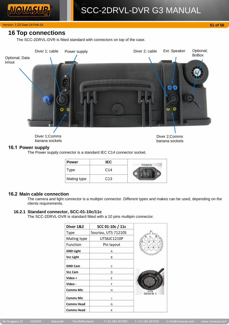
Version: 1.53 Date:24-Feb-16
SCC-2DRVL-DVR G3 MANUAL51 of 56
16 Top connectionsThe SCC-2DRVL-DVR is fitted standard with connectors on top of the case.
Power supplyThe Power supply connector is a standard IEC C14 connector socket.
Power IEC
Type C14
Mating type C13
Main cable connectionThe camera and light connector is a multipin connector. Different types and makes can be used, depending on theclients requirements.
16.2.1 Standard connector, SCC-01-10c/11cThe SCC-2DRVL-DVR is standard fitted with a 10 pins multipin connector.
Diver 1&2 SCC 01-10c / 11cType Souriau, UTS 71210SMating type UTS6JC1210PFunction Pin layoutGND Light A
Vcc Light B
GND Cam C
Vcc Cam D
Video + E
Video - F
Comms Mic H
Comms Mic J
Comms Head G
Comms Head K
Diver 1;Commsbanana sockets
Power supplyDiver 1; cable
Optional; Datain/out
Optional;BoBox
Diver 2; cable Ext. Speaker
Diver 2;Commsbanana sockets

Version: 1.53 Date:24-Feb-16
SCC-2DRVL-DVR G3 MANUAL52 of 56
16.2.2 Connector with sensor data, SCC-01-10d/11dThis connector also can interface a depth sensor or other sensor to the video text overlay.
Divers 1&2 SCC-01-10d/11dType Souriau, UTS 714E19SMating type UTS6JC14E19PFunction Pin layoutGND Light A
Vcc Light B
GND Cam C
Vcc Cam D
Video + E
Video - F
Depth V+ R
Comms Mic H
Comms Mic J
CP+ N
Data + L
Data - M
Depth Out+ P
Comms head G
Comms head K
16.2.3 Amphenol connector, SCC-01-10b/11bAmphenol series connector compatible with client standards
Divers 1&2 SCC-01-10b/11bType Amphenol, MS3102A-20-29S
Mating type MS3106A-20-29PFunction Pin layoutGND Light J
Vcc Light K
GND Cam F
Vcc Cam G
Video + A
Video - M
Comms Mic C
Comms Mic D
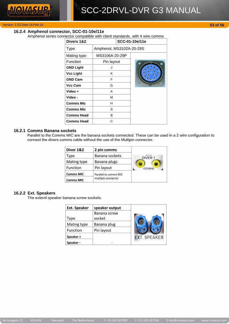
Version: 1.53 Date:24-Feb-16
SCC-2DRVL-DVR G3 MANUAL53 of 56
16.2.4 Amphenol connector, SCC-01-10e/11eAmphenol series connector compatible with client standards, with 4 wire comms
Divers 1&2 SCC-01-10e/11e
Type Amphenol, MS3102A-20-29S
Mating type MS3106A-20-29PFunction Pin layoutGND Light J
Vcc Light K
GND Cam F
Vcc Cam G
Video + A
Video - M
Comms Mic H
Comms Mic S
Comms Head B
Comms Head C
16.2.1 Comms Banana socketsParallel to the Comms MIC are the banana sockets connected. These can be used in a 2 wire configuration toconnect the divers comms cable without the use of the Multipin connector.
Diver 1&2 2 pin commsType Banana socketsMating type Banana plugsFunction Pin layoutComms MIC Parallel to comms MIC
multipin connectorComms MIC
16.2.2 Ext. SpeakersThe externl speaker banana screw sockets.
Ext. Speaker speaker output
TypeBanana screwsocket
Mating type Banana plugFunction Pin layoutSpeaker +
-Speaker -

Version: 1.53 Date:24-Feb-16
SCC-2DRVL-DVR G3 MANUAL54 of 56
Optional extra connectorsThe following extra connectors can be fitted on top of the SCC-2DRVL-DVR.
16.3.1 Data In connection RS232, SCC-01-49Data connector for data input of sensor to overlay. The SCC-2DRVL-DVR needs to be fitted with a OSD or DSIsensor interface board.SCC-01-49, RS232Type Bulgin,PX0412/08SMating type PX0410/08PFunction Pin layoutnc 1
nc 2
GND 3
nc 4
nc 5
nc 6
Rx 7
Tx 8
16.3.2 Data In/Out connection to DDG, SCC-01-50The Novasub DDG,Digital diver depth gauge can be connected to the SCC-2DRVL-DVR using above connector, orin combination with the SCC-01-50 connector.SCC-01-50OSD/DSI RS232 out/in, Depth (HART) outType Bulgin,PX0412/08SMating type PX0410/08PFunction Pin layoutnc 1
V+ (OSD/DSI) 2
GND 3
V+ (Depth) 4
Vout+ (Depth) 5Vout+(OSD/DSI) 6
Rx 7
Tx 8
This connections make it possible to use the Novasub DDG digital depth gauge with depth sensormeasurement. There are 2 ways of connecting the diver depth sensor UDS-3.
16.3.2.1 UDS-3 connected to SCCThe 2 wire UDS-3 depth sensor is wired into the multipin connector of the SCC. By using cable SCC-01-51,the UDS-3 is rewired internal to the DDG. The OSD-2 overlay boards is connected via de rs232 connectionwith the same cable SCC 01-51 to the DGG. The OSD-2 uses this depth input. Use cable SCC-01-51
16.3.2.2 UDS-3 connected to DDGThe 2 wire UDS-3 depth sensor is wired to the DDG digital depth gauge. The DDG rs232 is wired to the SCCrs232 port. The SCC-OSD-2 uses the rs232 depth input to display on the overlay. Use cable SCC-01-53

Version: 1.53 Date:24-Feb-16
SCC-2DRVL-DVR G3 MANUAL55 of 56
16.3.3 BoBoxThe Bobox connector is needed to connect the BoBox, the comms break-out box.
SCC break-out BoxBoBox SCC 01-43Type Souriau,UTS712E8SMatingtype UTS6JC12E8P
Function Pin layoutPTT DIVER1 1
PTT DIVER2 2
VCC 3
GND 4
SPEAKER 5
MIC+VOL 6
MIC 7
nc 8
16.3.4 Low voltage DC power supplyThe SCC can also be fitted with an external 10- 36 Vdc input.
SCC with external 10-36 vdc inputVdc input SCC 01-032Type Hirschmann CA3GSMating type CA3LDFunction Pin layoutnc 1
nc 2
GND 3
+VDC 4