dvi converter - orion display
TRANSCRIPT

• 201
1.09
.02
Address: 257-6, Gongdan-dong, Gumi-si, Gyeongsangbuk-do, KoreaTel : +82-2-6678-8533, Fax: +82-2-6678-8599
ORION CO.,LTD.www.oriondisplay.net
Thank you for purchasing our DVI Converter.Please read through this user's manual for safety before installing this product.
This product is manufactured for Multi Plasma display model only.
User's Manual
DVI Converter
ODC-10000

DVI Converter ODC-10000 Infinitely Expandable
ORION PDP CO., LTD. | 1
Product & AccessaryPlease check remote controller and all the accessories are included in the box
Contents1. Safety Precautions .....................................................................2
Cautions for DVI Converter ..........................................................2
Cautions for Electricity ...................................................................3
2. Names and functions ...............................................................4
Front side .........................................................................................4
Rear side ..........................................................................................5
3. DVI-Converter Installation and configuration method ........6
3-1. Installation ...............................................................................6
4. How to configure DVI Converter control mode ............8
4-1. RS-232C Interface mode ..................................................8
4-2. Ethernet Interface mode .....................................................9
4-3. IP address Setting ............................................................. 11
5. How to use ................................................................................. 16
5-1. Using the main key of DVI converter ......................... 16
5-2. How to use OSD ............................................................. 20
5-3. How to use MSCS .......................................................... 26
6. DVI Converter Protocol ......................................................... 41
7. Check followings before asking for service ............... 60
8. Specification............................................................................... 61
DVI Converter (ODC-10000) : 1EA User's Manual : 1EA
DVI Converter_Bracket : 2EA(Rack Mount Bracket)
PSW M3*8 : 6EA
DVI-D Cable
Power Cable
DVI Converter is a device to convert digital or analog signal into DVI image signal. 2 1.
independent DVI output ports can be used for the identical image output or for the
separate image output.
DVI Convert supports analog input of PC(RGB), COMPONENT(Y.Pb,Pr), and S-Video 2.
and digital input of DVI, HDMI, and HD-SDI. 2 LCD display windows show the input
modes and the DVI output resolutions, respectively. The input resolutions can be
selected from VGA(640x480) to UXGA(1600x1200), or DTV resolution from 480i 60Hz
to 1080P 60Hz
The information for the present input mode and output resolution is displayed on the 3.
LCD screen.
DVI Converter can be controlled through Rerial(RS-232C,) Ethernet or Front Key. 4.
According to user environment or preference, users can select the control method. If
Ethernet is selected, DVI Converter is controlled through LAN network. And, users can
control DVI Converter directly with Front Keys.
DVI Converter also can be controlled by a PC with the provided control program.5.
Product Introduction

DVI Converter ODC-10000
2 | ORION PDP CO., LTD.
Infinitely Expandable
ORION PDP CO., LTD. | 3
Cautions for DVI Converter Cautions for Electricity
Safety Precautions1.
Please do not use at the places �of hot and humid environment.
- It may damage the product.
Please be careful not to soak �unknown material or liquid into the product.
- It may damage the product.
Do not store or use flammables �like a combustible spray around the product.
- It has a possible danger of explosion or fire.
Do not put the product under �the direct sunlight or near to hot places.
- It may cause fire.
Do not disassemble, repair or alter the �product with users' own intention.
- I t may cause an electric shock or fire. If you need to test, adjust or repair the product, contact with an authorized service center.
If you detect smoke, smell or strange sound �from the product, stop using the product immediately, disconnect the power cable and contact with an authorized service center.
- It may cause an electric shock or fire.
Do not spray water directly on �the product.
- It may cause an electric shock or fire.
Carefully move the product not to �give any shock.
- It may cause product malfunction.
Please do not stack heavy �objects on top of the product.
- It may damage the product.
Please keep away from �children's reach.
- If they drop Remote Controller, it may hurt the children or cause product malfunction.
Do not touch the power cable �with wet hands.
- It may cause an electric shock.
Make sure the power plug is �properly connected.
- Loose connection may cause an electric shock.
Do not put a heavy object on the �cable or fold the cable.
- It may cause an electric shock or fire.
Do not connect to a multi- �power-socket together with many other electric products.
- It may cause an electric shock or fire.
Disconnect the power plug on �the occasion of lightning.
- It may damage the product.
Notice to usersClass A digital deviceIt is a device designed for business purpose with a safety certificate for electromagnetic interference, which user should be mindful of.Warning

DVI Converter ODC-10000
4 | ORION PDP CO., LTD.
Infinitely Expandable
ORION PDP CO., LTD. | 5
Rear side
INPUTA. SDI: Y/Cb/Cr signal, BNC Connector
DVI-D: TMDS signal, DVI Connector
HDMI: TMDS signal, HDMI Connector
PC: Computer RGB analog signal, D-Sub 15Pin
COMPONENT: DVD signal, DTV-YPbPr signal, BNC Connector
S-VIDEO: S-Video signal (Y/C), NTSC, PAL, SECAM, 4Pin Mini Din
VIDEO: Composite signal, NTSC, PAL, SECAM, BNC Connector
OUTPUTB. DVI1: TMDS signal, DVI Connector
DVI2: TMDS signal, DVI Connector
RS-232CC. IN: DVI Converter control, Daisy-chain input,
Firmware Update, 9Pin D-Sub
OUT: Daisy-chain output
ETHERNET PORTD. IEEE Standard UTP Cable, RJ45 Connector
AC INPUTE. AC 100~240V 50/60Hz
Front side
Names and functions2.
Input SourceA. DVI, HDMI, SDI, PC, COMPONENT, S-VIDEO, VIDEO
Output ResolutionB. VGA, SVGA, WVGA, XGA, SXGA, UXGA, UP, DOWN
DVI1 Status DisplayC. Displays DVI1 output information
DVI1 Select [SEL DVI 1]D. Select DVI 1 channel.
Serial/Ethernet Select [CTRL SET]E. Select communication mode between Serial (RS-232C) or Ethernet (LAN)
Navigation KeyF. Keys to control OSD "MENU, LEFT, RIGHT, UP, DOWN"
Rotary Switch [ID SET]G. Set the ID.
DVI2 Select [SEL DVI 2]H. Select DVI 1 channel.
Ethernet IP Setting [IP SET]I. Ping test for Ethernet communication mode.
DVI2 Status DisplayJ. Displays DVI2 output information
Power ON/OFF SwitchK. Power On/Off switch. (AC 100~240V, 50/60Hz).
A
B C
D EA B C D
E
F
GH
I JK

DVI Converter ODC-10000
6 | ORION PDP CO., LTD.
Infinitely Expandable
ORION PDP CO., LTD. | 7
ID 1
ID 4
ID 7
ID 2
ID 5
ID 8
ID 3
ID 6
ID 9
DVI-D_1
INPUT
OUTPUT
DVI-D_2
INPUT
OUTPUT
DVI-D_1
INPUT
OUTPUT
DVI-D_2
INPUT
OUTPUT
DVI-D_1
INPUT
OUTPUT
DVI-D_2
INPUT
OUTPUT
DVI-D_1
INPUT
OUTPUT
DVI-D_2
INPUT
OUTPUT
DVI-D_1
INPUT
OUTPUT
DVI-D_2
INPUT
OUTPUT
DVI-D_1
INPUT
OUTPUT
DVI-D_2
INPUT
OUTPUT
DVI-D_1
INPUT
OUTPUT
DVI-D_2
INPUT
OUTPUT
DVI-D_1
INPUT
OUTPUT
DVI-D_2
INPUT
OUTPUT
DVI-D_1
INPUT
OUTPUT
DVI-D_2
INPUT
OUTPUT
RS-232C
INPUTOUTPUT
RS-232C
INPUTOUTPUT
RS-232C
INPUTOUTPUT
RS-232C
INPUTOUTPUT
RS-232C
INPUTOUTPUT
RS-232C
INPUTOUTPUT
RS-232C
INPUTOUTPUT
RS-232C
INPUTOUTPUT
RS-232C
INPUTOUTPUT
DVI-Converter Installation and configuration method3.
Video Source
Control System
LCD / PDP Monitor
New MFC Controller
DVI ConverterRS-232 RS-485 USB Ethernet
RS-232
CVBS
S-Video
Component
PC
HD-SDI
HDMI
DVI
DVI Signal Distributor
DVI 2 Cable
DVI 1 Cable
Installation3-1.
1. Turn off the power of all connected input and output devices.
2. Connect DVI Converter and the PC with RS-232C cable.
If you want to use Ethernet, please refer to 4-2 to configure IP setting and connect LAN
cable.
3. Connect screen image source (DVI, HDMI, HD-SDI, PC, COMPONENT, S-VIDEO, and
CVBS) to the input port of DVI Converter.
4. Connect the DVI output of DVI Converter to MPDP or other Display devices.
5. Turn on the power of all connected input and output devices.
6. Power on and select input source and control necessary functions with controlling
device and the keys of DVI Converter.

DVI Converter ODC-10000
8 | ORION PDP CO., LTD.
Infinitely Expandable
ORION PDP CO., LTD. | 9
How to configure DVI Converter control mode4. RS-232C Interface mode4-1.
RS-232C Mode configuration1. Serial communication applies RS-232C standard. x
If the LED on "CTRL_SET" Button in the front is turned on, RS-232C command is not x
working. Press "CTRL_SET" Button and the LED is turned off, RS-232C command is
executed.
Ethernet mode is not available during RS-232C mode. x
It can be controlled through a serial port of MSCS (Multi Screen Control Software.) x
Communication configuration2. Transmission Type Asynchronous Serial Communication Parity bit None
Baud Rate 115200bps Stop bits 1
* When the LED on "CTRL_SET" Button in the front is turned off, RS-232C communication
mode is working.
The other communication modes are not available besides Key.
Connection Diagram3.
PDP 1 2 N-1 N
PC (Controller) DVI Converter RS-232C Distributor
RS-232C RS-232CRS-232CIN OUT
PDP PDP PDP
PDP 1 2 N-1 NPDP PDP PDP
IN OUT IN OUT IN OUT IN OUT
IN OUT IN OUT IN OUT IN OUT
PDP 1
IN OUT IN OUT IN OUT IN OUT
2 N-1 N
PC (Controller)
DVI Converter
RS-232C
IN
PDP PDP PDP
PDP 1 2 N-1 NPDP PDP PDP
INOUT INOUT INOUT INOUT
Ethernet Interface mode4-2.
Ethernet Mode configuration1. Ethernet communication is based on TCP/IP Protocol. According to DHCP configuration, x
it can be used as dynamic or static IP. Remote control is also available via World Wide
Web.
If the LED on "CTRL_SET" Button in the front is turned off, Ethernet command is not x
working. Press "CTRL_SET" Button and the LED is turned on, Ethernet mode is activated
and its command is executed.
RS-232C mode is not available during Ethernet mode. x
It can be controlled through a LAN port of MSCS (Multi Screen Control Software.) x
To use Ethernet mode, Ethernet is configured at Configuration mode in advance. x
Perform Ping test to check the connection status after configuration. x
If "Request timed out" response lasts more than 5 minutes, check the Ethernet
configuration.
If the problem continues, contact to your server manager. (H/W Port Number: 9761)
Ping Test �
The window as shown in the left side of the following pictures is popped up by pressing
"Window" key and "R" key at the same time. Type the IP address in the window.
e.g. "Ping 192.168.10.248 -t"
Then the DOS window is open and ping test start. (Ping test can be done at DOS window)

DVI Converter ODC-10000
10 | ORION PDP CO., LTD.
Infinitely Expandable
ORION PDP CO., LTD. | 11
Communication configuration2. Hardware Port 9761
DHCPOn IP Address / SubNet Mask / Gate Way / DNS Server configuration not necessary
Off IP Address / SubNet Mask / Gate Way / DNS Server configuration necessary
* When the LED on "CTRL_SET" Button in the front is turned on, Ethernet communication
mode is working.
The other communication modes are not available besides Key.
Connection Diagram3. Following diagram is an example of TCP/IP communication interface. x
Serial Daisy-Chain may vary depend on the installation circumstance. x
DVI converter must be connected before MPDP in the Ethernet mode. x
PDP 1 2 N-1 N
PC (Controller) DVI Converter RS-232C Distributor
Wireless(LAN)
Ethernet RS-232C
RS-232C
PDP PDP PDP
PDP 1 2 N-1 NPDP PDP PDP
IN OUT IN OUT IN OUT IN OUT
IN OUT IN OUT IN OUT IN OUT
IP address Setting4-3.
Direct PC Connection 1. Connect PC and DVI Converter with LAN cable1)
Connect DVI Converter and Computer with RS-232c cable. 2)
Turn on the power while pressing "IP Set" button. 3) POWER
DVI 1 DVI 2
DVI
SDI
COMPONENT
VIDEO
VGA
WVGA
SXGA
UP
SVGA
XGA
UXGA
DOWN
SEL DVI 1 SEL DVI 2
UP ID SET
MENU
DOWN
LEFT RIGHT
CTRL SET IP SET
HDMI
PC
S-VIDEO
DVI Converter
POWER
DVI 1 DVI 2
DVI
SDI
COMPONENT
VIDEO
VGA
WVGA
SXGA
UP
SVGA
XGA
UXGA
DOWN
SEL DVI 1 SEL DVI 2
UP ID SET
MENU
DOWN
LEFT RIGHT
CTRL SET IP SET
HDMI
PC
S-VIDEO
DVI Converter
Execute the provided program: “PIC Configuration.exe”When the program is loaded, 4)
the following window is popped up. Check the Com port in the PC and select the Com
Port from “Comport Select” and click “Open.”
Click “Get TCP/IP Info.” and check the IP address. 5)
Check whether the exact TCP/IP default values that saved in DVI Converter is loaded..

DVI Converter ODC-10000
12 | ORION PDP CO., LTD.
Infinitely Expandable
ORION PDP CO., LTD. | 13
Click “Set TCP/IP info.” 6)
Turn off the power of DVI Converter and turn it on.7)
Press “CTRL_SET” button in the front side of DVI Converter to turn on LED. When the 8)
LED is turned on, Ethernet communication mode is available. POWER
DVI 1 DVI 2
DVI
SDI
COMPONENT
VIDEO
VGA
WVGA
SXGA
UP
SVGA
XGA
UXGA
DOWN
SEL DVI 1 SEL DVI 2
UP ID SET
MENU
DOWN
LEFT RIGHT
CTRL SET IP SET
HDMI
PC
S-VIDEO
DVI Converter
POWER
DVI 1 DVI 2
DVI
SDI
COMPONENT
VIDEO
VGA
WVGA
SXGA
UP
SVGA
XGA
UXGA
DOWN
SEL DVI 1 SEL DVI 2
UP ID SET
MENU
DOWN
LEFT RIGHT
CTRL SET IP SET
HDMI
PC
S-VIDEO
DVI Converter
Select “TCP/IP” at “Start - Control Panel – Network” and type the Gateway 9)
values of DVI Converter in the IP address. The Subnet Mask value should be identical
with DVI Converter.
Execute MSCS V. 5.0 and insert IP address at Coomunication/Setup. Execute Pingtest 10)
to check communication satus.

DVI Converter ODC-10000
14 | ORION PDP CO., LTD.
Infinitely Expandable
ORION PDP CO., LTD. | 15
Network Connection2. Connect LAN cable from the network to the Ethernet port of DVI Converter.1)
Perform 1) ~ 4) steps of 4-3. 1.2)
Type in IP address directly and click “Set TCP/IP” 3)
If you use a static IP address, contact to your system administrator. ※
Turn off the power of DVI Converter and turn it on.4)
Press “CTRL_SET” button in the front side of DVI Converter to turn on LED. When the 5)
LED is turned on, Ethernet communication mode is available. POWER
DVI 1 DVI 2
DVI
SDI
COMPONENT
VIDEO
VGA
WVGA
SXGA
UP
SVGA
XGA
UXGA
DOWN
SEL DVI 1 SEL DVI 2
UP ID SET
MENU
DOWN
LEFT RIGHT
CTRL SET IP SET
HDMI
PC
S-VIDEO
DVI Converter
POWER
DVI 1 DVI 2
DVI
SDI
COMPONENT
VIDEO
VGA
WVGA
SXGA
UP
SVGA
XGA
UXGA
DOWN
SEL DVI 1 SEL DVI 2
UP ID SET
MENU
DOWN
LEFT RIGHT
CTRL SET IP SET
HDMI
PC
S-VIDEO
DVI Converter
Execute MSCS V. 5.0 and insert IP address at Coomunication/Setup. Execute Pingtest to 6)
check communication satus.
Execute MSCS V. 5.0 and insert IP address at Coomunication/Setup. Execute Pingtest to 7)
check communication satus.

DVI Converter ODC-10000
16 | ORION PDP CO., LTD.
Infinitely Expandable
ORION PDP CO., LTD. | 17
How to use5. Using the main key of DVI converter 5-1.
Input Source1. x DVI: Select DVI for DVI Converter Input.
HDMI: x Select HDMI for DVI Converter Input.
SDI: x Select SDI for DVI Converter Input .
PC: x Select PC for DVI Converter Input .
COMPONENT: x Select COMPONENT for DVI Converter Input.
S-VIDEO: x Select S-VIDEO for DVI Converter Input.
VIDEO: x Select VIDEO for DVI Converter Input.
Output Resolution2. x VGA: Select VGA (640x480, 60Hz) for DVI Converter Output.
SVGA x : Select SVGA (800x600, 60Hz) for DVI Converter Output.
WVGA: x Select WVGA (853x480, 60Hz) for DVI Converter Output.
XGA: x Select XGA (1024x768, 60Hz) for DVI Converter Output.
SXGA: x Select SXGA (1280x1024, 60Hz) for DVI Converter Output.
UXGA: x Select UXGA (1600x1200, 60Hz) for DVI Converter Output.
UP: x Select various resolutions for DVI Converter Output.
DOWN: x Select various resolutions for DVI Converter Output.
POWER
DVI 1 DVI 2
DVI
SDI
COMPONENT
VIDEO
VGA
WVGA
SXGA
UP
SVGA
XGA
UXGA
DOWN
SEL DVI 1 SEL DVI 2
UP ID SET
MENU
DOWN
LEFT RIGHT
CTRL SET IP SET
HDMI
PC
S-VIDEO
DVI Converter
POWER
DVI 1 DVI 2
DVI
SDI
COMPONENT
VIDEO
VGA
WVGA
SXGA
UP
SVGA
XGA
UXGA
DOWN
SEL DVI 1 SEL DVI 2
UP ID SET
MENU
DOWN
LEFT RIGHT
CTRL SET IP SET
HDMI
PC
S-VIDEO
DVI Converter
DVI1 Status Display3. x Display the version information of DVI Converter Channel1 at the
time of power on booting.
e.g. "Boot..v091028.3": Revision 3, October 28, 2009. -
Display the current Input source, Output resolution and Lock Mode x
Status after power on booting sequence.
- e.g. First line: "IN:DVI Lock"/ Second line "OUT:640x480,60":
Input source is DVI, Output Resolution is 640x480, 60Hz and
Key Lock On Mode.
- e.g. First line: "IN:DVI" / Second line "OUT:640x480,60": Input
source is DVI, Output Resolution is 640x480, 60Hz and Key
Lock Off Mode.
DVI1 Selector [SEL_DVI 1]4. x It is used to control DVI1 Channel.
If the LED on "SEL_DVI 1" button is turned off, it is impossible to x
control DVI1 Channel and if the LED on "SEL_DVI 1" button is turned
on, DVI1 Channel can be controlled.
When you press "SEL_DVI 1" button, the LED on "SEL_DVI 2" button x
is turned off and unable to control DVI2 Channel
Serial/Ethernet Selector [CTRL_SET]5. x It is used to select the communication mode of DVI Converter;
Serial(RS-232C) or Ethernet(LAN.)
If the LED on ""CTRL_SET" button is turned off, it can be controlled x
as Serial (RS-232C) mode.
If the LED on ""CTRL_SET" button is turned on, it can be controlled x
as Ethernet(LAN) mode.
DVI 1
Boot..v091028.3
DVI 1
IN:DVI LockOUT:640x480,60
DVI 1
IN:DVIOUT:640x480,60
POWER
DVI 1 DVI 2
DVI
SDI
COMPONENT
VIDEO
VGA
WVGA
SXGA
UP
SVGA
XGA
UXGA
DOWN
SEL DVI 1 SEL DVI 2
UP ID SET
MENU
DOWN
LEFT RIGHT
CTRL SET IP SET
HDMI
PC
S-VIDEO
DVI Converter
POWER
DVI 1 DVI 2
DVI
SDI
COMPONENT
VIDEO
VGA
WVGA
SXGA
UP
SVGA
XGA
UXGA
DOWN
SEL DVI 1 SEL DVI 2
UP ID SET
MENU
DOWN
LEFT RIGHT
CTRL SET IP SET
HDMI
PC
S-VIDEO
DVI Converter
DVI Converter ODC-10000
18 | ORION PDP CO., LTD.
Infinitely Expandable
ORION PDP CO., LTD. | 19
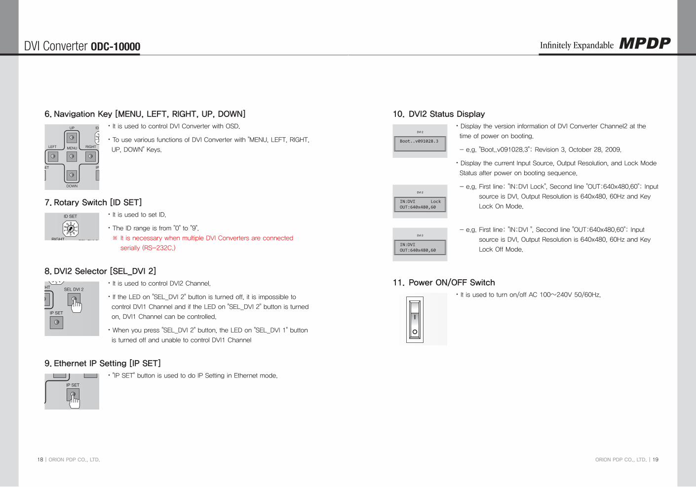
Navigation Key [MENU, LEFT, RIGHT, UP, DOWN]6. x It is used to control DVI Converter with OSD.
To use various functions of DVI Converter with "MENU, LEFT, RIGHT, x
UP, DOWN" Keys.
Rotary Switch [ID SET]7. x It is used to set ID.
The ID range is from "0" to "9". x
※ It is necessary when multiple DVI Converters are connected
serially (RS-232C.)
DVI2 Selector [SEL_DVI 2]8. x It is used to control DVI2 Channel.
If the LED on "SEL_DVI 2" button is turned off, it is impossible to x
control DVI1 Channel and if the LED on "SEL_DVI 2" button is turned
on, DVI1 Channel can be controlled.
When you press "SEL_DVI 2" button, the LED on "SEL_DVI 1" button x
is turned off and unable to control DVI1 Channel
Ethernet IP Setting [IP SET]9. x "IP SET" button is used to do IP Setting in Ethernet mode.
POWER
DVI 1 DVI 2
DVI
SDI
COMPONENT
VIDEO
VGA
WVGA
SXGA
UP
SVGA
XGA
UXGA
DOWN
SEL DVI 1 SEL DVI 2
UP ID SET
MENU
DOWN
LEFT RIGHT
CTRL SET IP SET
HDMI
PC
S-VIDEO
DVI Converter
POWER
DVI 1 DVI 2
DVI
SDI
COMPONENT
VIDEO
VGA
WVGA
SXGA
UP
SVGA
XGA
UXGA
DOWN
SEL DVI 1 SEL DVI 2
UP ID SET
MENU
DOWN
LEFT RIGHT
CTRL SET IP SET
HDMI
PC
S-VIDEO
DVI ConverterPOWER
DVI 1 DVI 2
DVI
SDI
COMPONENT
VIDEO
VGA
WVGA
SXGA
UP
SVGA
XGA
UXGA
DOWN
SEL DVI 1 SEL DVI 2
UP ID SET
MENU
DOWN
LEFT RIGHT
CTRL SET IP SET
HDMI
PC
S-VIDEO
DVI Converter
POWER
DVI 1 DVI 2
DVI
SDI
COMPONENT
VIDEO
VGA
WVGA
SXGA
UP
SVGA
XGA
UXGA
DOWN
SEL DVI 1 SEL DVI 2
UP ID SET
MENU
DOWN
LEFT RIGHT
CTRL SET IP SET
HDMI
PC
S-VIDEO
DVI Converter
DVI2 Status Display10. x Display the version information of DVI Converter Channel2 at the
time of power on booting.
e.g. "Boot..v091028.3": Revision 3, October 28, 2009. -
Display the current Input Source, Output Resolution, and Lock Mode x
Status after power on booting sequence.
- e.g. First line: "IN:DVI Lock", Second line "OUT:640x480,60": Input
source is DVI, Output Resolution is 640x480, 60Hz and Key
Lock On Mode.
- e.g. First line: "IN:DVI ", Second line "OUT:640x480,60": Input
source is DVI, Output Resolution is 640x480, 60Hz and Key
Lock Off Mode.
Power ON/OFF Switch11. x It is used to turn on/off AC 100~240V 50/60Hz.
DVI 2
Boot..v091028.3
DVI 2
IN:DVI LockOUT:640x480,60
DVI 2
IN:DVI OUT:640x480,60
POWER
DVI 1 DVI 2
DVI
SDI
COMPONENT
VIDEO
VGA
WVGA
SXGA
UP
SVGA
XGA
UXGA
DOWN
SEL DVI 1 SEL DVI 2
UP ID SET
MENU
DOWN
LEFT RIGHT
CTRL SET IP SET
HDMI
PC
S-VIDEO
DVI Converter

DVI Converter ODC-10000
20 | ORION PDP CO., LTD.
Infinitely Expandable
ORION PDP CO., LTD. | 21
How to use OSD 5-2.
Picture Mode1. Brightness, Contrast, sharpness, Color and Tint menus can be adjusted by Picture mode. x
"Color" and "Tint" menus are not available for DVI, HDMI, HDSDI, and PC inputs. x
"Tint" menu is not available for S-VIDEO and VIDEO inputs, if the video standard is PAL. x
1) Press "Menu" button of Front Key to load Menu screen.
Select "Picture" using UP/DOWN buttons.2)
Sub-menu is activated by pressing "RIGHT" button.3)
Select the item you want to adjust using UP/DOWN buttons.4)
The values can be controlled by LEFT/RIGHT buttons.5)
Press "Menu" button to finish OSD after adjustment. 6)
Brightness y : Adjustment range is from 0 to 100.
Contrast y : Adjustment range is from 0 to 100.
Sharpness y : Adjustment range is from 0 to 28.
Color y : Adjustment range is from 0 to 100.
Tint y : Adjustment range is from 0 to 90.
UP
MENU
DOWN
LEFT RIGHT
Feature
Picture
Screen
Display
Brightness
Contrast
Sharpness
Colour
Tint
40
83
14
50
45
Move Select ExitMENU
Picture
Feature
Picture
Screen
Display
Brightness
Contrast
Sharpness
Colour
40
83
14
50
Move Select ExitMENU
Picture
NTSC OSD (Video, S-Video) PAL OSD (Video, S-Video)
Screen Mode2. H. Position, V. Position, Phase, Frequency, Auto and Image Blend menus can be adjusted xby Screen mode.
H. Position, V. Position, Phase, Frequency, and Auto menus are available only for PC input. x
Image Blend Menu is available only for PIP and the transparency of the sub picture may xbe changed during Image Blend control.
Screen mode control is not usable for PIP. x
1) Press "Menu" button of Front Key to load Menu screen.
Select "Picture" using UP/DOWN buttons.2)
Sub-menu is activated by pressing "RIGHT" button.3)
Select the item you want to adjust using UP/DOWN buttons.4)
The values can be controlled by LEFT/RIGHT buttons.5)
Press "Menu" button to finish OSD after adjustment. 6)
Mode y : 16:9, LB (16:9), LBS (16:9), 14:9, LB (14:9), LBS (14:9), and Toggle can be selected.
H.Position y : Adjustment range is from 0 to 100. (PC only)
V.Position y : Adjustment range is from 0 to 100. (PC only)
Phase y : Adjustment range is from 0 to 63. (PC Only)
Frequency y : Adjustment range is from 0 to 50. (PC Only)
Auto y : Auto tracking is executed by clicking "RIGHT" button. (PC Only)
Image Blend y : Adjustment range is from 0 to 100. (PIP Mode Only)
UP
MENU
DOWN
LEFT RIGHT
Feature
Picture
Screen
Display
Mode
H.position
V.position
Phase
Frequency
Auto
50
50
0
100
Move Select ExitMENU
16 : 9
Picture
Screen
PC OSD
Feature
Picture
Screen
Display
Image Blend 100
Move Select ExitMENU
Picture
Screen
PIP OSD

DVI Converter ODC-10000
22 | ORION PDP CO., LTD.
Infinitely Expandable
ORION PDP CO., LTD. | 23
Feature Mode3. Background and Initialize menus can be adjusted by Feature mode. x
During Background control, the transparency of the OSD menu may be changed. x
1) Press "Menu" button of Front Key to load Menu screen.
Select "Picture" using UP/DOWN buttons.2)
Sub-menu is activated by pressing "RIGHT" button.3)
Select the item you want to adjust using UP/DOWN buttons.4)
The values can be controlled by LEFT/RIGHT buttons.5)
Press "Menu" button to finish OSD after adjustment. 6)
Feature
Picture
Screen
Display
Move Select ExitMENU
Background
Initialize
10
Feature
Background y : Adjustment range is from 0 to 10.
UP
MENU
DOWN
LEFT RIGHT
Following menu is appeared by selecting Initialize. x
Press "RIGHT" button at the following screen. 1)
Feature
Picture
Screen
Display
Move Select ExitMENU
No
Yes
Are you sure ?
Feature
If you select "No" or Menu to return to Initialize menu.2)
If you select "Yes" for User data initialization.3)
DVI Converter ODC-10000
24 | ORION PDP CO., LTD.
Infinitely Expandable
ORION PDP CO., LTD. | 25
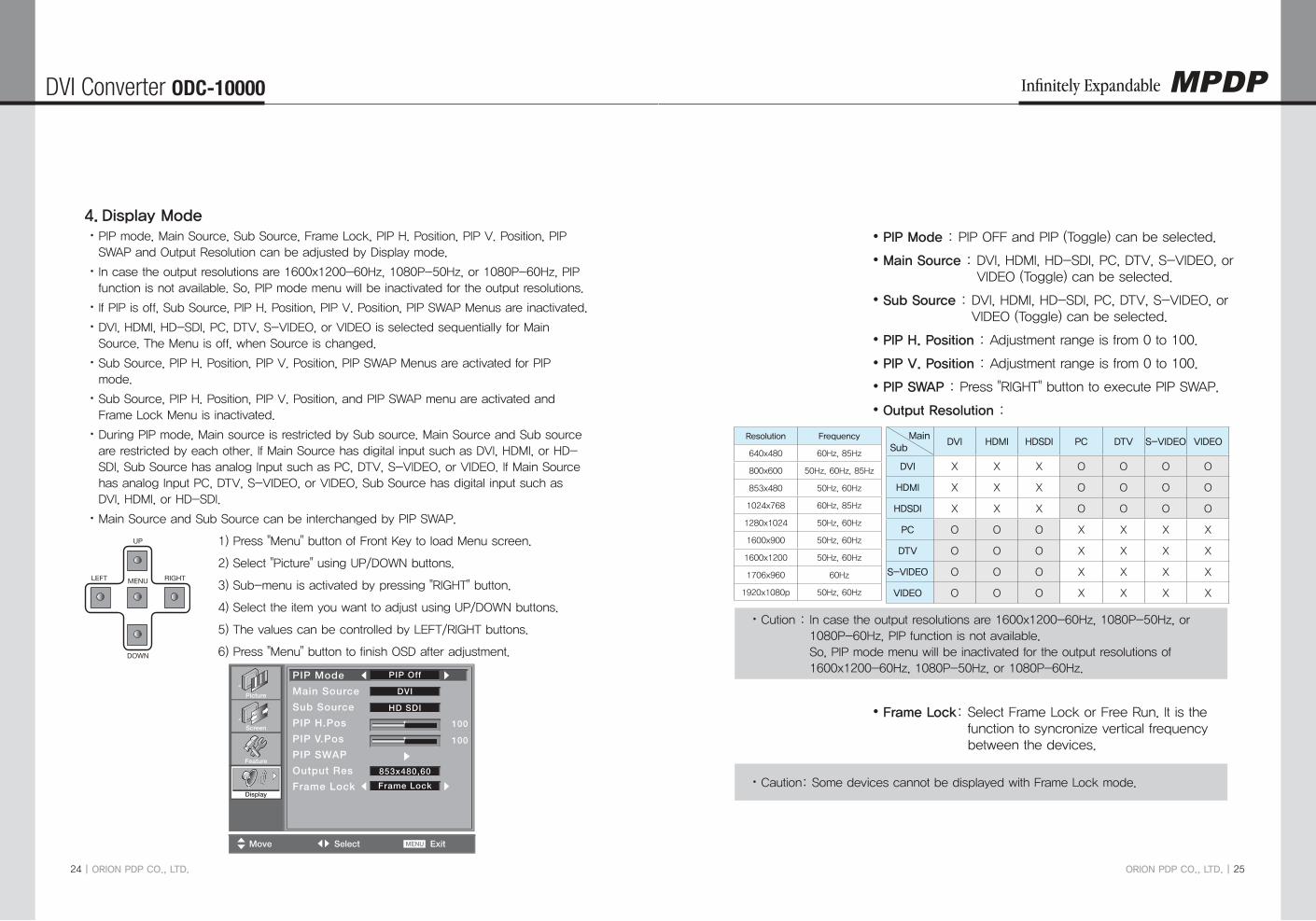
Display Mode4. PIP mode, Main Source, Sub Source, Frame Lock, PIP H. Position, PIP V. Position, PIP xSWAP and Output Resolution can be adjusted by Display mode.
In case the output resolutions are 1600x1200-60Hz, 1080P-50Hz, or 1080P-60Hz, PIP xfunction is not available. So, PIP mode menu will be inactivated for the output resolutions.
If PIP is off, Sub Source, PIP H. Position, PIP V. Position, PIP SWAP Menus are inactivated. x
DVI, HDMI, HD-SDI, PC, DTV, S-VIDEO, or VIDEO is selected sequentially for Main xSource. The Menu is off, when Source is changed.
Sub Source, PIP H. Position, PIP V. Position, PIP SWAP Menus are activated for PIP xmode.
Sub Source, PIP H. Position, PIP V. Position, and PIP SWAP menu are activated and xFrame Lock Menu is inactivated.
During PIP mode, Main source is restricted by Sub source. Main Source and Sub source xare restricted by each other. If Main Source has digital input such as DVI, HDMI, or HD-SDI, Sub Source has analog Input such as PC, DTV, S-VIDEO, or VIDEO. If Main Source has analog Input PC, DTV, S-VIDEO, or VIDEO, Sub Source has digital input such as DVI, HDMI, or HD-SDI.
Main Source and Sub Source can be interchanged by PIP SWAP. x
1) Press "Menu" button of Front Key to load Menu screen.
Select "Picture" using UP/DOWN buttons.2)
Sub-menu is activated by pressing "RIGHT" button.3)
Select the item you want to adjust using UP/DOWN buttons.4)
The values can be controlled by LEFT/RIGHT buttons.5)
Press "Menu" button to finish OSD after adjustment. 6)
Feature
Picture
Screen
Display
100
100
Move Select ExitMENU
PIP Off
DVI
HD SDI
Frame Lock
853x480,60
PIP Mode
Main Source
Sub Source
PIP H.Pos
PIP V.Pos
PIP SWAP
Output Res
Frame LockDisplay
UP
MENU
DOWN
LEFT RIGHT
PIP Mode y : PIP OFF and PIP (Toggle) can be selected.
Main Source y : DVI, HDMI, HD-SDI, PC, DTV, S-VIDEO, or VIDEO (Toggle) can be selected.
Sub Source y : DVI, HDMI, HD-SDI, PC, DTV, S-VIDEO, or VIDEO (Toggle) can be selected.
PIP H. Position y : Adjustment range is from 0 to 100.
PIP V. Position y : Adjustment range is from 0 to 100.
PIP SWAP y : Press "RIGHT" button to execute PIP SWAP.
Output Resolution y :
Frame Lock y : Select Frame Lock or Free Run. It is the function to syncronize vertical frequency between the devices.
Cution : In case the output resolutions are 1600x1200-60Hz, 1080P-50Hz, or x1080P-60Hz, PIP function is not available. So, PIP mode menu will be inactivated for the output resolutions of 1600x1200-60Hz, 1080P-50Hz, or 1080P-60Hz.
Caution: Some devices cannot be displayed with Frame Lock mode. x
Resolution Frequency
640x480 60Hz, 85Hz
800x600 50Hz, 60Hz, 85Hz
853x480 50Hz, 60Hz
1024x768 60Hz, 85Hz
1280x1024 50Hz, 60Hz
1600x900 50Hz, 60Hz
1600x1200 50Hz, 60Hz
1706x960 60Hz
1920x1080p 50Hz, 60Hz
MainSub
DVI HDMI HDSDI PC DTV S-VIDEO VIDEO
DVI X X X O O O O
HDMI X X X O O O O
HDSDI X X X O O O O
PC O O O X X X X
DTV O O O X X X X
S-VIDEO O O O X X X X
VIDEO O O O X X X X

DVI Converter ODC-10000
26 | ORION PDP CO., LTD.
Infinitely Expandable
ORION PDP CO., LTD. | 27
How to use MSCS (Multi Screen Control Software)5-3.
Introduction �
MSCS Ver. 5.0 is software to control DVI Converter. x
DVI converter can be controlled by a computer with MSCS. x
Main Image of MSCS (Multi Screen Control system)
Program End1. Click Exit from File (Ctrl+X) to end the program. x
Setting 'Com Port'2. Com Port connects or disconnects the communication between DVI Converter and x
MPDP.
Connet MPDP to DVI Converter Com Port via RS-232C cable. x
Go to MSCS Menu -> Communication and set Com Port. x
Click ‘Connect’ or Press ‘Ctrl+C’ to initiate the communication between the
computer and the DVI Converter.
In order to disconnect communication, click 'Disconnect' using mouse or press 'Ctrl+D' x
using keyboard.
Connect: x Connect the communication between the computer and the DVI Converter.
Disconnect: x Disconnect the communication between the computer and the DVI
Converter.
SetUp: x Configure the Serial port of a computer to communicate with DVI Converter.
e.g. COM1, COM17 …
Communication configuration Sub-Communication
Baud Rate 115200 bps
Data Bit 8 Bits
Stop Bit 1 Bit
Parity Bit None Parity Bit

DVI Converter ODC-10000
28 | ORION PDP CO., LTD.
Infinitely Expandable
ORION PDP CO., LTD. | 29
Port Setting 3. Please select "Menu → Communication → Setup" or "Ctrl+U" to start SetUp. x
Serial : x Set the serial communication as a default communication.
Com Port : x Set the port of a PC to communicate with MPDP.
Baud Rate : x Fixed at 115200bps.
Caution: Users cannot change the Baud rate. ※
Socket : x Set the Ethernet LAN communication.
Edit Box : x Set the IP address.
Port Number : x Fixed as 9761.
Caution: Users cannot change the port number. ※
Ping Test: x Test the IP address.
Connect : x Connect the communication.
LAN : x Set the Ethernet communication.
"New design/Last design" setting4. When Com Port is successfully connected, pop-up window for "New design/Last design" x
appears.
New/Last Design Set
Click "Open New Design" to prepare new configuration. x
Click "Open Last Design" to go to last design before closing. x
When the connection is successfully completed after setting Com Port, following x
Message dialog is displayed. The dialog window will be disappeared in 1 second.

DVI Converter ODC-10000
30 | ORION PDP CO., LTD.
Infinitely Expandable
ORION PDP CO., LTD. | 31
DVI Converter 5. To use DVI Converter, go to MSCS Menu → Device → DVI Converter or press "Ctrl+V" x
using Keyboard.
DVI Converter Main Dialog
ID �
Set the ID of DVI Converter. The ID can be selected from 1 to 9. x
CMND �
Select the channel of DVI converter to control. x
One of DVI Channel 1(DVIC1), DVI Channel 2(DVIC2), and ALL DVI Channel can be x
selected.
Input Mode �
Select the input mode of DVI Converter. x
One of DVI, HDMI, HDSDI, PC, DTV, S-VIDEO, and VIDEO can be selected. x
Set : x Select one mode from 7 Input Modes and execute.

DVI Converter ODC-10000
32 | ORION PDP CO., LTD.
Infinitely Expandable
ORION PDP CO., LTD. | 33
Output Resolution �
Set the output resolution of DVI Converter. x
Resolution frequency
640 x 480 60Hz / 85Hz
800 x 600 50Hz / 60Hz / 85Hz
853 x 480 50Hz / 60Hz
1024 x 768 60Hz / 85Hz
1280 x 1024 50Hz / 60Hz
1600 x 900 50Hz / 60Hz
1600 x 1200 50Hz / 60Hz
1706 x 960 60Hz
1920 x1080p 50Hz / 60Hz
Set : x Set the output resolution.
OSD Information �
The DVI converter input and input resolution are displayed on the screen. x
Aspect Ratio �
Set or change the screen ratio (Horizontal: Vertical). x
16 : 9 : x Set the screen ratio as 16:9 wide screen.
4 : 3 : x Set the screen ratio as 4:3.
LB(Letter Box) : x Expand the screen image to remove the black patterns at the top and bottom portions of the screen..
LBS(Letter Box Subtitle) : x Expand the screen with the subtitle to the top portion. (The bottom portion remains with black pattern).
16:9
16:9(LB)
14:9
4:3
16:9(LBS)
14:9(LB) 14:9(LBS)

DVI Converter ODC-10000
34 | ORION PDP CO., LTD.
Infinitely Expandable
ORION PDP CO., LTD. | 35
Key Lock Mode �
Lock the front key of DVI Converter not to turn On or Off. x
Status �
Display the DVI Converter status (Input Source, Input Resolution, Output Resolution, x
Aspect Ratio, PIP Mode, Test Pattern, Key Lock, Fan Check, Firmware Version, MSCS
Version information)
Status Dialog
Picture Control �
Control the Brightness, Contrast, Sharpness, Color, and Tint of the DVI Converter. x
Brightness : x The range of "Brightness" you can adjust is 0 to 100.
Contrast : x The range of "Contrast" you can adjust is 0 to 100.
Sharpness : x The range of "Sharpness" you can adjust is 0 to 28.
Color : x The range of "Color" you can adjust is 0 to 100
Tint : x The range of "Tint" you can adjust is 0 to 90.
Firmware Default : x Initialize the adjusted values to the default values.
Picture Control Dialog

DVI Converter ODC-10000
36 | ORION PDP CO., LTD.
Infinitely Expandable
ORION PDP CO., LTD. | 37
Pattern �
Select the Test Pattern (Red, Blue, 8-Color, 16-Gray, Green, White, White (10%), Screen) x
Set : x Set or change the Pattern.
Pattern Dialog
Lock/FreeRun �Lock : Default setting. It is used when MPDP is configured as the default display. x
If the vertical frequency of input signal and out signal is identical, output is generated according to vertical synchronization.
FreeRun : This function is used when the default display is not MPDP and screen image xis not displayed. It generates its own output vertical frequency regardless of input signal. If screen image is displayed, use Lock mode.
Lock/FreeRun can be configured by the keypad of DVI converter besides MSCS. xWhile Menu OSD is not displayed, FreeRun mode can be selected by pressing UP key and Lock mode by DOWN key.
Tracking �Control the Screen size, sharpness, and position of DVI Converter with PC input mode. x
In case alignment doesn't work through "Tracking Auto" command, users can tune finely xthrough "Manual Tracking".
"Manual Tracking" window enables users to set Frequency, Phase, LineStart and xPixelStart.
Detail adjustment steps are as follows. x
1) Tune "Phase" until the vertical lines are clearly adjusted..
2) Tune "LineStart" to adjust vertical alignment. "PixelStart" for horizontal alignment.
3) Adjust "Frequency" if alignment is still wrong.
If you adjust "Frequency", repeat step 1) and 2) to fit alignment.
Adjustable range is as follows
Frequency : x The range of "Frequency" you can adjust is -50 to 50.
Phase : x The range of "Phase" you can adjust is 0 to 63.
Linestart : x The range of "Linestart" you can adjust is -23 to 10.
Pixelstart : x The range of "Pixelstart" you can adjust is -50 to 40.
Auto Tracking : x Automatic alignment for DVI Converter screens.
Auto Calibration : x Automatic color control for DVI Converter screen.
Tracking Dialog

DVI Converter ODC-10000
38 | ORION PDP CO., LTD.
Infinitely Expandable
ORION PDP CO., LTD. | 39
PIP( Picture In Picture ) �
A variety of images can be displayed with the PIP function of DVI converter. To activate x
PIP, click "PIP" in the Mode. The position of sub-picture can be controlled by clicking - /
+ buttons o increase or decrease the number or directly type in the numbers at Edit box.
Various input sources can be used. To set the sub-input, click the sub-input combo box x
and select sub-input.
Main screen and sub-screen can be swapped with the PIP Swap function. Press "Set" x
button at the right side of "PIP Swap." If you want to return to previous screen, press
"Normal" button at the right side of "PIP Swap".
Mode : x Normal mode - Normal screen without PIP (PIP Off)
PIP mode-Sub-screen is displayed at the lower right corner of the screen. (PIP
On)
Position : x Horizontal - Adjust the horizontal location of PIP. Adjustable range 0~100
Vertical - Adjust the vertical location of PIP. Adjustable range 0~100
Sub Input : x Set the input for PIP. One of DVI, HDMI, HDSDI, PC, DTV, S-VIDEO, and
VIDEO can be selected for sub-input.
According to the main input, the sub-input can be restricted. If the main input is a ※
digital input such as DVI, HDMI or HD-SDI, the sub-input should be an analog input
such as PC, DTV, S-VIDEO or Video. If the main input is an analog input the sub-
input should be a digital input.
PIP Swap : x OFF - Return to previous locations of swapped Main Source Input screen
and Sub Source Input screen.
ON - Exchange the locations of Main Source Input screen and Sub Source
Input screen.
Cution : In case the output resolutions are 1600x1200-60Hz, 1080P-50Hz, or x
1080P-60Hz, PIP function is not available.
So, PIP mode menu will be inactivated for the output resolutions of
1600x1200-60Hz, 1080P-50Hz, or 1080P-60Hz.
Auto Calibration function
Auto Calibration is the automatic function to adjust the color coordinates of RGB, DTV x
or DVD inputs for obtaining the closet value with the white balance value that adjusted
by DVI. In case the manual adjustment of white balance for RGB, DTV or DVD inputs is
impossible or difficult, it is recommended that using only “Auto Calibration” for white
balance adjustment.
Auto calibration is only applicable for RGB, DTV or DVD. It is recommended that using x
the function after adjusting white balance. If white balance is not adjusted prior to Auto
calibration, it follows the color coordinates of the previous color coordinates DVI output.
100% saturation 8 color bar signals of SMTPE standard should be inputted for Auto x
calibration.
The standard signal for RGB input is 8 color-bar signal with XGA 60Hz resolution, 8 x
color-bar signal with 1080i 60Hz resolution for DTV input and 8 color-bar signal with
480i 60Hz resolution for DVD input.
If the signal is not satisfy the 8 color bar signal standard, Auto calibration may not work x
properly. The input signal level of RGB, DTV and DVD should be 1.5V at white. Please
refer to following examples for the standard signal wave.
8 color bar output

DVI Converter ODC-10000
40 | ORION PDP CO., LTD.
Infinitely Expandable
ORION PDP CO., LTD. | 41
PIP( Picture In Picture ) Dialog
Main
SubDVI HDMI HDSDI PC DTV S-VIDEO VIDEO
DVI X X X O O O O
HDMI X X X O O O O
HDSDI X X X O O O O
PC O O O X X X X
DTV O O O X X X X
S-VIDEO O O O X X X X
VIDEO O O O X X X X
Introduction1. This chapter introduces PROTOCOL between DVI Converter and the controlling devices like a computer for better understanding and effective use. So, it focuses on brief introduction of functions and PROTOCOL without further technical explanation.
ID:1
CH 1 CH 2 CH 1 CH 2 CH 1 CH 2 CH 1 CH 2
Controller(Computer)
Tx/Rx Line ID:2 ID:8 ID:9
※ Connection format may vary depends on environmental condition or users’ preference.<Communication Diagram>
Communication Setting1.1.
Transmission type: Asynchronous Serial Communication -
Connection type: Daisy Chain -
Baud Rate: 115200bps -
Parity bit: None -
Stop bits: 1 -
Protocol Format2.
Send To PDP2.1.
STX Command Length Data ETX
1 byte 1 byte 1 byte Variable 1 byte
ID Ch1/Ch2 Other Data
1 byte 1 byte N byte
It is a format to send commands to DVI Converter. The set of the designated ID is working -as commanded. However, a virtual ID value is generated by adding 100 to the original DVI Converter ID to distinguish the ID from the ID of MPDP.
STX (0x02): The initiation Code. The beginning of Protocol. (Fixed value) -
Command: The code of actual execution (Dynamic value) -
Length: The length of "Data" area. (Dynamic value: "0"~"255") -
Data: "ID," "Ch1/Ch2" and other Data area (Dynamic value) -
ID: The code to distinguish DVI Converter. It is allocated in the rage of "101"~"109." -
Ch1/Ch2: The classification code for "Channel1" is "0x01", "Channel2" for "0x00. " (Dynamic value) -
ETX (0x03): The end of Protocol. (Fixed value) -
DVI Converter Protocol6.

DVI Converter ODC-10000
42 | ORION PDP CO., LTD.
Infinitely Expandable
ORION PDP CO., LTD. | 43
Receive From DVI Converter2.2.
STX CMD Length Data Check Sum ETX
1 byte 1 byte 1 byte Variable 1 byte 1 byte
ID Ch1/Ch2 Other Data
1 byte 1 byte N byte
It is a format to respond to certain commands. The difference from "Send to PDP" is the existence of "Check Sum". -STX (0x02): The initiation Code. The beginning of Protocol. (Fixed value) -Command: The code of actual execution (Dynamic value) -Length: The length of "Data" area. (Dynamic value: "0"~"255") -Data: "ID," "Ch1/Ch2" and other Data area (Dynamic value) -ID: The code to distinguish DVI Converter. It is allocated in the rage of "101"~"109." -Ch1/Ch2: The classification code for "Channel1" is "0x01", "Channel2" for "0x00." (Dynamic value) -Check Sum: Add all the values of "STX~Data" and execute "Not" operation. -ETX (0x03): The end of Protocol. (Fixed value) -
Command3.
Infomation3.1.
Display information on the DVI Converter screen. (Input source and resolution by OSD) -It is available only during Power on status. -
Send to MPDP -
STX CMD LengthData
ETXID Ch1/Ch2
Value 0x02 0x42 0x02 Variable Variable 0x03
* ID range (Program): 0x65(101) ~ 0x6D(109)* Ch1/Ch2: Ch1 (0x01), Ch2 (0x00)
Receive from MPDP -
STX CMD LengthData
Check Sum ETXID Ch1/Ch2
Value 0x02 0x42 0x02 Variable Variable Variable 0x03
* ID range (Program): 0x65(101) ~ 0x6D(109)* Ch1/Ch2: Channel1 (0x01), Channel2 (0x00)* Check Sum: Add all the values of “STX ~ Data” and execute “Not” operation.
"Information" Communication Sequence -* Wait for the response for 40msec after sending commands. In case of response failure, it is recommended to
send the command again.* It is recommended not to give the other command or change the resolution during transmission.* ALL DVIC command is executed Channel2 and Channel1 sequentially. (Channel2 → Channel1)
Information Command transmission (to Ch2) →← Information Response transmission (from Ch2)
Information Command transmission (to Ch1) →← Information Response transmission (from Ch1)
Input-Mode Change3.2.
Change input mode without screen scaling. -It is available only during Power on status. -CMD: 0xA4 (DVI ), 0xA5 (HDMI), 0xA6 (HDSDI), 0xA7 (PC), 0xA8 (DTV), 0xAA (S-VIDEO), 0xAB (VIDEO) -
Send to MPDP -
STX CMD LengthData
ETXID Ch1/Ch2
Value 0x02 Variable 0x02 Variable Variable 0x03
* ID range (Program): 0x65(101) ~ 0x6D(109)* Ch1/Ch2: Channel1 (0x01), Channel2 (0x00)
Receive from MPDP -
STX CMD LengthData
Check Sum ETXID Ch1/Ch2
Value 0x02 Variable 0x02 Variable Variable Variable 0x03
* ID range (Program): 0x65(101) ~ 0x6D(109)* Ch1/Ch2: Channel1 (0x01), Channel2 (0x00)* Check Sum: Add all the values of “STX ~ Data” and execute “Not” operation.
"Input-Mode Change" Communication Sequence -* Wait for the response for 40msec after sending commands. In case of response failure, it is recommended to
send the command again.* It is recommended not to give the other command or change the resolution during transmission.* ALL DVIC command is executed Channel2 and Channel1 sequentially. (Channel2 → Channel1)
Input-Mode Change Command transmission (to Ch2) →← Input-Mode Change Response transmission (from Ch2)
Input-Mode Change Command transmission (to Ch1) →← Input-Mode Change Response transmission (from Ch1)

DVI Converter ODC-10000
44 | ORION PDP CO., LTD.
Infinitely Expandable
ORION PDP CO., LTD. | 45
Test Pattern3.3.
Checking the image quality of DVI Converter with the built-in pattern -It is available only during Power on status. -
Send to MPDP -
STX CMD LengthData
ETXID Ch1/Ch2 Value
Value 0x02 0x96 0x03 Variable Variable Variable 0x03
* ID range (Program): 0x65(101) ~ 0x6D(109)* Ch1/Ch2: Channel1 (0x01), Channel2 (0x00)* Value:
Screen (0x01), White (0x02), Red (0x03), Green (0x04), Blue (0x05), 8-Color (0x06), 10%-White (0x07), x16-Gray (0x08)
Receive from MPDP -
STX CMD LengthData
Check Sum ETXID Ch1/Ch2
Value 0x02 0x96 0x02 Variable Variable Variable 0x03
* ID range (Program): 0x65(101) ~ 0x6D(109)* Ch1/Ch2: Channel1 (0x01), Channel2 (0x00)* Check Sum: Add all the values of “STX ~ Data” and execute “Not” operation.
"Test Pattern" Communication Sequence -* Wait for the response for 40msec after sending commands. In case of response failure, it is recommended to
send the command again.* It is recommended not to give the other command or change the resolution during transmission.* ALL DVIC command is executed Channel2 and Channel1 sequentially. (Channel2 → Channel1)
Test Pattern Command transmission (to Ch2) →← Test Pattern Response transmission (from Ch2)
Test Pattern Command transmission (to Ch1) →← Test Pattern Response transmission (from Ch1)
Key Lock Mode3.4.
The command for restricting Front Key function of DVI Converter -It is available only during Power on status. -
Send to MPDP -
STX CMD LengthData
ETXID Ch1/Ch2 Value
Value 0x02 0x5C 0x03 Variable Variable Variable 0x03
* ID range (Program): 0x65(101) ~ 0x6D(109)* Ch1/Ch2: Channel1 (0x01), Channel2 (0x00)
* Value: Key Lock Mode On (0x01), Key Lock Mode Off (0x02)
Receive from MPDP -
STX CMD LengthData
Check Sum ETXID Ch1/Ch2
Value 0x02 0x5C 0x02 Variable Variable Variable 0x03
* ID range (Program): 0x65(101) ~ 0x6D(109)* Ch1/Ch2: Channel1 (0x01), Channel2 (0x00)* Check Sum: Add all the values of “STX ~ Data” and execute “Not” operation.
"Key Lock Mode" Communication Sequence -* Wait for the response for 40msec after sending commands. In case of response failure, it is recommended to
send the command again.* It is recommended not to give the other command or change the resolution during transmission.* ALL DVIC command is executed Channel2 and Channel1 sequentially. (Channel2 → Channel1)
Key Lock Mode Command transmission (to Ch2) →← Key Lock Mode Response transmission (from Ch2)
Key Lock Mode Command transmission (to Ch1) →← Key Lock Mode Response transmission (from Ch1)
PIP Mode3.5.
The command for PIP function of DVI Converter -It is available only during Power on status. -
Send to MPDP -
STX CMD LengthData
ETXID Ch1/Ch2 Value
Value 0x02 0x98 0x03 Variable Variable Variable 0x03
* ID range (Program): 0x65(101) ~ 0x6D(109)* Ch1/Ch2: Channel1 (0x01), Channel2 (0x00)* Value: Normal (0x01), PIP Mode (0x02)
Receive from MPDP -
STX CMD LengthData
Check Sum ETXID Ch1/Ch2
Value 0x02 0x98 0x02 Variable Variable Variable 0x03
* ID range (Program): 0x65(101) ~ 0x6D(109)* Ch1/Ch2: Channel1 (0x01), Channel2 (0x00)* Check Sum: Add all the values of “STX ~ Data” and execute “Not” operation.
"PIP Mode" Communication Sequence -* Wait for the response for 40msec after sending commands. In case of response failure, it is recommended to
send the command again.* It is recommended not to give the other command or change the resolution during transmission.

DVI Converter ODC-10000
46 | ORION PDP CO., LTD.
Infinitely Expandable
ORION PDP CO., LTD. | 47
* ALL DVIC command is executed Channel2 and Channel1 sequentially. (Channel2 → Channel1)
PIP Mode Command transmission (to Ch2) →← PIP Mode Response transmission (from Ch2)
PIP Mode Command transmission (to Ch1) →← PIP Mode Response transmission (from Ch1)
PIP Position3.6.
The command for controlling the PIP screen position -It is available only during Power on status. -CMD: 0x5D ( PIP H. Position), 0x5E (PIP V. Position) -
Send to MPDP -
STX CMD LengthData
ETXID Ch1/Ch2 Value
Value 0x02 Variable 0x03 Variable Variable Variable 0x03
* ID range (Program): 0x65(101) ~ 0x6D(109)* Ch1/Ch2: Channel1 (0x01), Channel2 (0x00)* Value:
PIP H. Position: 0 (0x00) ~ 100 (0x64) xPIP V. Position: 0 (0x00) ~ 100 (0x64) x
Receive from MPDP -
STX CMD LengthData
Check Sum ETXID Ch1/Ch2
Value 0x02 Variable 0x02 Variable Variable Variable 0x03
* ID range (Program): 0x65(101) ~ 0x6D(109)* Ch1/Ch2: Channel1 (0x01), Channel2 (0x00)* Check Sum: Add all the values of “STX ~ Data” and execute “Not” operation.
"PIP Position" Communication Sequence -* Wait for the response for 40msec after sending commands. In case of response failure, it is recommended to
send the command again.* It is recommended not to give the other command or change the resolution during transmission.* ALL DVIC command is executed Channel2 and Channel1 sequentially. (Channel2 → Channel1)
PIP Position Command transmission (to Ch2) →← PIP Position Response transmission (from Ch2)
PIP Position Command transmission (to Ch1) →← PIP Position Response transmission (from Ch1)
PIP Swap Mode3.7.
The command for interchanging the positions of main picture and sub picture. -It is available only for PIP mode during Power on status. -
Send to MPDP -
STX CMD LengthData
ETXID Ch1/Ch2 Value
Value 0x02 0x99 0x03 Variable Variable Variable 0x03
* ID range (Program): 0x65(101) ~ 0x6D(109)* Ch1/Ch2: Channel1 (0x01), Channel2 (0x00)* Value:
Normal Mode (0x01) - Main picture and Sub picture are displayed without position change. xSwap Mode (0x02) - The positions of Main picture and Sub picture are interchanged. x
Receive from MPDP -
STX CMD LengthData
Check Sum ETXID Ch1/Ch2
Value 0x02 0x99 0x02 Variable Variable Variable 0x03
* ID range (Program): 0x65(101) ~ 0x6D(109)* Ch1/Ch2: Channel1 (0x01), Channel2 (0x00)* Check Sum: Add all the values of “STX ~ Data” and execute “Not” operation.
"PIP Swap" Communication Sequence -* Wait for the response for 40msec after sending commands. In case of response failure, it is recommended to
send the command again.* It is recommended not to give the other command or change the resolution during transmission.* ALL DVIC command is executed Channel2 and Channel1 sequentially. (Channel2 → Channel1)
PIP Swap Command transmission (to Ch2) →← PIP Swap Response transmission (from Ch2)
PIP Swap Command transmission (to Ch1) →← PIP Swap Response transmission (from Ch1)
PIP Input-Mode Change3.8.
The command for changing PIP Input mode without screen scaling. -It is available only for PIP mode during Power on status. -

DVI Converter ODC-10000
48 | ORION PDP CO., LTD.
Infinitely Expandable
ORION PDP CO., LTD. | 49
Send to MPDP -
STX CMD LengthData
ETXID Ch1/Ch2 Value
Value 0x02 0xA0 0x03 Variable Variable Variable 0x03
* ID range (Program): 0x65(101) ~ 0x6D(109)* Ch1/Ch2 : Channel1 (0x01), Channel2 (0x00)* Value
DVI (0x01), HDMI (0x02), HDSDI (0x03), PC (0x04), DTV (0x05), S-VIDEO (0x06), VIDEO (0x07) x If the Main Input-Mode is DVI, HDMI, or HDSDI, PIP Input-Mode cannot be DVI, HDMI, or HDSDI. x If the Main Input-Mode is PC, DTV, S-VIDEO, or VIDEO, PIP Input-Mode cannot be PC, DTV, S-VIDEO, or xVIDEO. Main Input-Mode and PIP Input-Mode cannot have the same input source. x
Receive from MPDP -
STX CMD LengthData
Check Sum ETXID Ch1/Ch2
Value 0x02 0xA0 0x02 Variable Variable Variable 0x03
* ID range (Program): 0x65(101) ~ 0x6D(109)* Ch1/Ch2: Channel1 (0x01), Channel2 (0x00)* Check Sum: Add all the values of “STX ~ Data” and execute “Not” operation.
"Input-Mode Change" Communication Sequence -* Wait for the response for 40msec after sending commands. In case of response failure, it is recommended to
send the command again.* It is recommended not to give the other command or change the resolution during transmission.* ALL DVIC command is executed Channel2 and Channel1 sequentially. (Channel2 → Channel1).
Input-Mode Change Command transmission (to Ch2) →← Input-Mode Change Response transmission (from Ch2)
Input-Mode Change Command transmission (to Ch1) →← Input-Mode Change Response transmission (from Ch1)
Get PIP Status3.9.
The command for checking PIP status information. -It is available only during Power on status. -CMD: 0x5F -
Send to MPDP -
STX CMD LengthData
ETXID Ch1/Ch2
Value 0x02 0x5F 0x02 Variable Variable 0x03
* ID range (Program): 0x65(101) ~ 0x6D(109)* Ch1/Ch2: Channel1 (0x01), Channel2 (0x00)
Receive from MPDP -
STX CMD LengthData Check
SumETX
ID Ch1/Ch2 Status
Value 0x02 0x5F 0x07 Variable Variable … Variable 0x03
* ID range (Program): 0x65(101) ~ 0x6D(109)* Ch1/Ch2: Channel1 (0x01), Channel2 (0x00)* Check Sum: Add all the values of “STX ~ Data” and execute “Not” operation.* Status
No. Data Length Explanation
1 PIP Mode 1 byte 1:Normal, 2: PIP
2 PIP H. Position 1 byte 0 (0x00) ~ 100 (0x64)
3 PIP V. Position 1 byte 0 (0x00) ~ 100 (0x64)
4 PIP Input Source 1 byte 1: DVI, 2: HDMI, 3: HDSDI, 4: PC, 5: DTV, 6: S-Video, 7: Video
5 PIP Swap Mode 1 byte 1: Normal, 2: Swap
"PIP Status Get" Communication Sequence -* Wait for the response for 40msec after sending commands. In case of response failure, it is recommended to
send the command again.* It is recommended not to give the other command or change the resolution during transmission.* ALL DVIC command is executed Channel2 and Channel1 sequentially. (Channel2 → Channel1)
PIP Status Get Command transmission (to Ch2) →← PIP Status Get Response transmission (from Ch2)
PIP Status Get Command transmission (to Ch1) →← PIP Status Get Response transmission (from Ch1)
Output Resolution Change3.10.
The command for changing the output resolution of DVI Converter -It is available only for PIP mode during Power on status. In case of PIP mode, it becomes PIP Normal mode. -
Send to MPDP -
STX CMD LengthData
ETXID Ch1/Ch2 Value
Value 0x02 0xA2 0x03 Variable Variable Variable 0x03
* ID range (Program): 0x65(101) ~ 0x6D(109)* Ch1/Ch2: Channel1 (0x01), Channel2 (0x00)* Value
640x480(60Hz) (0x01), 640x480(85Hz) (0x02), 800x600(50Hz) (0x03), 800x600(60Hz) (0x04), x800x600(85Hz) (0x05), 853x480(50Hz) (0x06), 853x480(60Hz) (0x07), 1024x768(60Hz) (0x08), 1024x768(85Hz) (0x09), 1280x1024(50Hz)(0x0A), 1280x1024(60Hz) (0x0B), 1600x900(50Hz) (0x0C), 1600x900(60Hz) (0x0D), 1600x1200(50Hz) (0x0E), 1600x1200(60Hz) (0x0F), 1706x960(60Hz) (0x10), 1080P(50Hz)(0x11), 1080P(60Hz)(0x12)

DVI Converter ODC-10000
50 | ORION PDP CO., LTD.
Infinitely Expandable
ORION PDP CO., LTD. | 51
Receive from MPDP -
STX CMD LengthData
Check Sum ETXID Ch1/Ch2
Value 0x02 0xA2 0x02 Variable Variable Variable 0x03
* ID range (Program): 0x65(101) ~ 0x6D(109)* Ch1/Ch2: Channel1 (0x01), Channel2 (0x00)* Check Sum: Add all the values of “STX ~ Data” and execute “Not” operation.
"Output Resolution Change" Communication Sequence -* Wait for the response for 40msec after sending commands. In case of response failure, it is recommended to
send the command again.* It is recommended not to give the other command or change the resolution during transmission.* ALL DVIC command is executed Channel2 and Channel1 sequentially. (Channel2 → Channel1)
Output Resolution Change Command transmission (to Ch2) →← Output Resolution Change Responsetransmission (from Ch2)
Output Resolution Change Command transmission (to Ch1) →← Output Resolution Change Response transmission (from Ch1)
Get Test Pattern Status3.11.
The command for checking Test Pattern information. -It is available only during Power on status. -
Send to MPDP -
STX CMD LengthData
ETXID Ch1/Ch2
Value 0x02 0x60 0x02 Variable Variable 0x03
* ID range (Program): 0x65(101) ~ 0x6D(109)* Ch1/Ch2: Channel1 (0x01), Channel2 (0x00)
Receive from MPDP -
STX CMD LengthData Check
SumETX
ID Ch1/Ch2 Status
Value 0x02 0x60 0x3 Variable Variable Variable Variable 0x03
* ID range (Program): 0x65(101) ~ 0x6D(109)* Ch1/Ch2: Channel1 (0x01), Channel2 (0x00)* Check Sum: Add all the values of “STX ~ Data” and execute “Not” operation.* Status Screen (0x01), White (0x02), Red (0x03), Green (0x04), Blue (0x05), 8-Color (0x06), 10%-White (0x07), 16-Gray (0x08)
"Test Pattern Status Get" Communication Sequence -* Wait for the response for 40msec after sending commands. In case of response failure, it is recommended to
send the command again.* It is recommended not to give the other command or change the resolution during transmission.* ALL DVIC command is executed Channel2 and Channel1 sequentially. (Channel2 → Channel1)
Test Pattern Status Get Command transmission (to Ch2) →← Test Pattern Status Get Response transmission (from Ch2)
Test Pattern Status Get Command transmission (to Ch1) →← Test Pattern Status Get Response transmission (from Ch1)
Auto-Calibration3.12.
The command for adjusting Gain and Offset of ADC with 100% 8-Color input. It is available only for PC/DTV input. -It is available only during Power on status. -
Send to MPDP -
STX CMD LengthData
ETXID Ch1/Ch2
Value 0x02 0x80 0x02 Variable Variable 0x03
* ID range (Program): 0x65(101) ~ 0x6D(109)* Ch1/Ch2: Channel1 (0x01), Channel2 (0x00)
Receive from MPDP -
STX CMD LengthData
Check Sum ETXID Ch1/Ch2
Value 0x02 0x80 0x03 Variable Variable Variable 0x03
* ID range (Program): 0x65(101) ~ 0x6D(109)* Ch1/Ch2: Channel1 (0x01), Channel2 (0x00)* Check Sum: Add all the values of “STX ~ Data” and execute “Not” operation.
"Auto-Calibration" Communication Sequence -* Wait for the response for 40msec after sending commands. In case of response failure, it is recommended to
send the command again.* It is recommended not to give the other command or change the resolution during transmission.* ALL DVIC command is executed Channel2 and Channel1 sequentially. (Channel2 → Channel1)
Auto-Calibration Command transmission (to Ch2) →← Auto-Calibration Response transmission (from Ch2)
Auto-Calibration Command transmission (to Ch1) →← Auto-Calibration Response transmission (from Ch1)

DVI Converter ODC-10000
52 | ORION PDP CO., LTD.
Infinitely Expandable
ORION PDP CO., LTD. | 53
Screen Mode3.13.
The command for controlling the aspect ratio of DVI Converter. -It is available only during Power on status and not available for PIP mode. -
Send to MPDP -
STX CMD LengthData
ETXID Ch1/Ch2 Value
Value 0x02 0x95 0x03 Variable Variable Variable 0x03
* ID range (Program): 0x65(101) ~ 0x6D(109)* Ch1/Ch2: Channel1 (0x01), Channel2 (0x00)* Value:
16:9 (0x01): Set the aspect ratio as 16:9 x4:3 (0x02): Set the aspect ratio as 4:3 x16:9(LB) (0x03): Set the aspect ratio as 16:9 Letter-Box. It is used for the screen with black areas at the xtop and bottom. 16:9(LBS)(0x04): Set the aspect ratio as 16:9 Letter-Box Subtitle. It is used for the images with sub-title and xblack area at the top and bottom of the screen. 14:9 (0x05): Set the aspect ratio as 14:9 x14:9(LB) (0x06): Set the aspect ratio as 14:9 Letter-Box. It is used for the screen with black areas at the xtop and bottom. 14:9(LBS)(0x07): Set the aspect ratio as 14:9 Letter-Box Subtitle. It is used for the screen with black areas xat the top and bottom.
Receive from MPDP -
STX CMD LengthData
Check Sum ETXID Ch1/Ch2
Value 0x02 0x95 0x02 Variable Variable Variable 0x03
* ID range (Program): 0x65(101) ~ 0x6D(109)* Ch1/Ch2: Channel1 (0x01), Channel2 (0x00)* Check Sum: Add all the values of “STX ~ Data” and execute “Not” operation.
"Screen Mode" Communication Sequence -* Wait for the response for 40msec after sending commands. In case of response failure, it is recommended to
send the command again.* It is recommended not to give the other command or change the resolution during transmission.* ALL DVIC command is executed Channel2 and Channel1 sequentially. (Channel2 → Channel1)
Screen Mode Command transmission (to Ch2) →← Screen Mode Response transmission (from Ch2)
Screen Mode Command transmission (to Ch1) →← Screen Mode Response transmission (from Ch1)
Tracking Mode3.14.
The command for adjusting screen alignment automatically or manually or loading predetermined value in PC -RGB modeCMD: -0x4A (Auto Tracking), 0x4B (Get Tracking Values), 0x4C (Frequency-tracking), 0x4D (Phase-tracking), 0x4E (Line-Start tracking), 0x4F (Pixel-Start tracking)It is available only during Power on status. -
Send to MPDP -Auto-tracking/Get Tracking Values: Adjusting PC (RGB) screen alignment automatically.A.
STX CMD LengthData
ETXID Ch1/Ch2
Value 0x02 Variable 0x02 Variable Variable 0x03
Frequency/Phase/Line-Start/Pixel-Start-tracking: Adjusting PC (RGB) screen alignment manually.B.
STX CMD LengthData
ETXID Ch1/Ch2 Tracking Value
Value 0x02 Variable 0x03 Variable Variable Variable 0x03
* ID range (Program): 0x65(101) ~ 0x6D(109)* Ch1/Ch2: Channel1 (0x01), Channel2 (0x00)* Value:
Frequency range: 77(0x4D) ~ 177(0xB1) /Actual Value (-50 ~ +50) /Actual Value + 127 (0x7F) xPhase range: 127(0x7F) ~ 158(0x9E) /Actual Value (0 ~ +31) /Actual Value + 127 (0x7F) xLine Start range: 104(0x68) ~ 137(0x89) /Actual Value (-23 ~ +10) /Actual Value + 127 (0x7F) xPixel Start range: 77(0x4D) ~ 167(0xA7) /Actual Value (-50 ~ +40) /Actual Value + 127 (0x7F) x
Receive from MPDP -Auto-tracking, Frequency/Phase/Line-Start/Pixel-Start-trackingA.
STX CMD LengthData
Check Sum ETXID Ch1/Ch2
Value 0x02 Variable 0x03 Variable Variable Variable 0x03
Get Tracking ValuesB.
STX CMD LengthData Check
SumETX
ID Ch1/Ch2 Tracking Value
Value 0x02 Variable 0x05 Variable Variable … Variable 0x03
* ID range (Program): 0x65(101) ~ 0x6D(109)* Ch1/Ch2: Channel1 (0x01), Channel2 (0x00)* Tracking Value
Frequency range: 77(0x4D) ~ 177(0xB1) / Actual Value (-50 ~ +50) / Actual Value + 127 (0x7F) xPhase range: 127(0x7F) ~ 158(0x9E) / Actual Value (0 ~ +31) / Actual Value + 127 (0x7F) xLine Start range: 104(0x68) ~ 137(0x89) / Actual Value (-23 ~ +10) / Actual Value + 127 (0x7F) xPixel Start range: 77(0x4D) ~ 167(0xA7) / Actual Value (-50 ~ +40) / Actual Value + 127 (0x7F) x

DVI Converter ODC-10000
54 | ORION PDP CO., LTD.
Infinitely Expandable
ORION PDP CO., LTD. | 55
"Tracking Mode" Communication Sequence -* Wait for the response for 40msec after sending commands. In case of response failure, it is recommended to
send the command again. * It is recommended not to give the other command or change the resolution during transmission.* ALL DVIC command is executed Channel2 and Channel1 sequentially. (Channel2 → Channel1)
Tracking Mode Command transmission (to Ch2) →← Tracking Mode Response transmission (from Ch2)
Tracking Mode Command transmission (to Ch1) →← Tracking Mode Response transmission (from Ch1)
*”Get Tracking Values” command is executed Channel2 and Channel1 sequentially. (Channel2 → Channel1)
Get Tracking Mode Command transmission (to Ch2) →← Get Tracking Mode Response transmission (from Ch2)
Get Tracking Mode Command transmission (to Ch1) →← Get Tracking Mode Response transmission (from Ch1)
Default Data Load (Picture Control Data)3.15.
The command for initializing the adjusted values and apply the built-in values. -It is available only during Power on status. -This commands should be executed with care, because all the adjusted values will be erased. -
Send to MPDP -
STX CMD LengthData
ETXID Ch1/Ch2
Value 0x02 0x97 0x02 Variable Variable 0x03
* ID range (Program): 0x65(101) ~ 0x6D(109)* Ch1/Ch2: Channel1 (0x01), Channel2 (0x00)
Receive from MPDP -
STX CMD LengthData
Check Sum ETXID Ch1/Ch2
Value 0x02 0x97 0x02 Variable Variable Variable 0x03
* ID range (Program): 0x65(101) ~ 0x6D(109)* Ch1/Ch2: Channel1 (0x01), Channel2 (0x00)* Check Sum: Add all the values of “STX ~ Data” and execute “Not” operation.
"Default Data Load" Communication Sequence -* Wait for the response for 40msec after sending commands. In case of response failure, it is recommended to
send the command again. * It is recommended not to give the other command or change the resolution during transmission.* ALL DVIC command is executed Channel2 and Channel1 sequentially. (Channel2 → Channel1)
Default Data Load Command transmission (to Ch2) →← Default Data Load Response transmission (from Ch2)
Default Data Load Command transmission (to Ch1) →← Default Data Load Response transmission (from Ch1)
Graphic User Mode Control3.16.
The command for adjusting the values of Brightness, Contrast, Sharpness, Color, and Tint. -CMD: 0x8F (Brightness), 0x90 (Contrast), 0x91 (Sharpness), 0x92 (Color), 0x93 (Tint) -It is available only during Power on status. -The adjusted value will not be applied during stand-by phase or no input signal. -So, there must be input signals of corresponding mode to apply adjusted values.
Send to MPDP -
STX CMD LengthData
ETXID Ch1/Ch2 Value
Value 0x02 Variable 0x03 Variable Variable Variable 0x03
* ID range (Program): 0x65(101) ~ 0x6D(109)* Ch1/Ch2: Channel1 (0x01), Channel2 (0x00)* Value:
Brightness ("0" ~ "100"), Contrast ("0" ~ "100"), Sharpness ("0" ~ "28"), Color ("0" ~ "100"), Tint ("0" ~ "100") x
Receive from MPDP -
STX CMD LengthData
Check Sum ETXID Ch1/Ch2
Value 0x02 Variable 0x02 Variable Variable Variable 0x03
* ID range (Program): 0x65(101) ~ 0x6D(109)* Ch1/Ch2: Channel1 (0x01), Channel2 (0x00)* Check Sum: Add all the values of “STX ~ Data” and execute “Not” operation.
"Graphic User Mode Control" Communication Sequence -* Wait for the response for 40msec after sending commands. In case of response failure, it is recommended to
send the command again. * It is recommended not to give the other command or change the resolution during transmission.* ALL DVIC command is executed Channel2 and Channel1 sequentially. (Channel2 → Channel1)

DVI Converter ODC-10000
56 | ORION PDP CO., LTD.
Infinitely Expandable
ORION PDP CO., LTD. | 57
Graphic User Mode Control Command transmission
(to Ch2)→←
Graphic User Mode Control Response transmission
(from Ch2)
Graphic User Mode Control Command transmission
(to Ch1)→←
Graphic User Mode Control Response transmission
(from Ch1)
Get Current Status3.17.
The command for checking current DVI Converter status information. -CMD: 0x87 -It is available only during Power on status. -
Send to MPDP -
STX CMD LengthData
ETXID Ch1/Ch2
Value 0x02 0x87 0x02 Variable Variable 0x03
* ID range (Program): 0x65(101) ~ 0x6D(109)* Ch1/Ch2: Channel1 (0x01), Channel2 (0x00)
Receive from MPDP -
STX CMD LengthData Check
SumETX
ID Ch1/Ch2 Status
Value 0x02 0x87 0x17 Variable Variable … Variable 0x03
* ID range (Program): 0x65(101) ~ 0x6D(109)* Ch1/Ch2: Channel1 (0x01), Channel2 (0x00)* Check Sum: Add all the values of “STX ~ Data” and execute “Not” operation.* Status (21byte)
No. Data Length Explanation
1 Input Source 1 byte 1: DVI, 2: HDMI, 3: HDSDI, 4: PC, 5: DTV, 6: S-Video, 7: Video
2 Input Resolution 1 byte The value for the detected input resolution
3 Output Resolution 1 byte The value for the configures output resolution
4 Not Used 1 byte
5 Aspect Ratio 1 byte 1: 16:9, 2: 4:3, 3: 16:9(LB), 4: 16:9(LBS), 5: 14:9, 6: 14:9(LB), 7: 14:9(LBS)
6 PIP 1 byte 1: Normal, 2: PIP
7~10 Not Used 4 byte
11 Test Pattern 1 byte1: Screen, 2: White, 3: Red, 4: Green, 5: Blue, 6: 8-Color,7: 10%-White,
8: 16-Gray, 9: 66%-White, 10: 33%-White, 11:Black
12 Not Used 1 byte
13 Frame Lock 1 byte 0x01: Frame Lock, 0x02: Free Run
14 Key Lock 1 byte 1: On, 2: Off
15~21 F/W Version 7 byteYear: 2 byte, Month: 2byte, Day: 2byte, Rev: 1byte
Ex) December 29th, 2012 Rev. 2→ 0x01 0x02 0x01 0x02 0x02 0x09 0x02
< The value for the detected input resolution (It is different from the supporting resolution) >
Resolution Value Resolution Value Resolution Value
640x480x60 0(0x00) 720Px50 21(0x15) 1360x768x60 45(0x2D)
640x480x85 1(0x01) 576Px50 22(0x16) 640x350x85 46(0x2E)
800x600x56 2(0x02) 480Px60 23(0x17) 640x480x75 47(0x2F)
800x600x60 3(0x03) 1920x1080ix60 24(0x18) 640x480x72 48(0x30)
800x600x75 4(0x04) 1920x1080ix50 25(0x19) 1152x864x75 49(0x31)
800x600x85 5(0x05) 1280x720Px60 26(0x1A) 1280x720x60 50(0x32)
853x480x60 6(0x06) 1280x720Px50 27(0x1B) 1280x768x75 51(0x33)
1024x768x60 7(0x07) PAL 28(0x1C) 1280x1024x75 52(0x34)
1024x768x70 8(0x08) SECAM 29(0x1D) 1366x768x50 53(0x35)
1024x768x75 9(0x09) PALP 30(0x1E) 1400x1050x50 54(0x36)
1024x768x85 10(0x0A) NTSC 31(0x1F) 1440x900x60 55(0x37)
1280x768x60 11(0x0B) NTSCP 32(0x20) 576ix50 56(0x38)
1280x960x60 12(0x0C) Unknown 34(0x22) 480ix60 57(0x39)
1280x1024x60 13(0x0D) No-Signal 35(0x23) 1080px60 58(0x3A)
1366x768x60 14(0x0E) 853x480x50 38(0x26) 1080px50 59(0x3B)
1600x1200x60 15(0x0F) 1280x1024x50 39(0x27) 1920x1080px60 60(0x3C)
1400x1050x60 16(0x10) 1360x768x50 40(0x28) 1920x1080px50 61(0x3D)
1706x960x60 17(0x11) 1600x900x50 41(0x29) 1024x576x50 62(0x3E)
1080ix60 18(0x12) 1600x900x60 42(0x2A) 1024x576x60 63(0x3F)
1080ix50 19(0x13) 1600x1200x50 43(0x2B)
720Px60 20(0x14) 800x600x50 44(0x2C)
※ The resolutions written in red or italic letters can be detected, but they are not supporting resolutions.
"Get Current Status" Communication Sequence -* Wait for the response for 800msec after sending commands. In case of response failure, it is recommended to
send the command again. * It is recommended not to give the other command or change the resolution during transmission.* ALL DVIC command is executed Channel2 and Channel1 sequentially. (Channel2 → Channel1)
Get Current Status Command transmission (to Ch2) →← Get Current Status Response transmission (from Ch2)
Get Current Status Command transmission (to Ch1) →← Get Current Status Response transmission (from Ch1)

DVI Converter ODC-10000
58 | ORION PDP CO., LTD.
Infinitely Expandable
ORION PDP CO., LTD. | 59
Get Picture Control Data3.18.
The command for check the current picture control data (Brightness, Contrast, Sharpness, Color, Tint) of DVI -Converter.It is available only during Power on status. -
Send to MPDP -
STX CMD LengthData
ETXID Ch1/Ch2
Value 0x02 0x88 0x02 Variable Variable 0x03
* ID range (Program): 0x65(101) ~ 0x6D(109)* Ch1/Ch2: Channel1 (0x01), Channel2 (0x00)
Receive from MPDP -
STX CMD LengthData Check
SumETX
ID Ch1/Ch2 Values
Value 0x02 0x88 0x34 Variable Variable … Variable 0x03
* ID range (Program): 0x65(101) ~ 0x6D(109)* Ch1/Ch2: Channel1 (0x01), Channel2 (0x00)* Values (39 byte)
No. Data Length Explanation
1 User Mode – Brightness 1 byte Range: 0(0x00) ~ 100(0x64)
2 User Mode – Contrast 1 byte Range: 0(0x00) ~ 100(0x64)
3 User Mode – Sharpness 1 byte Range: 0(0x00) ~ 28(0x1C)
4 User Mode – Color 1 byte Range: 0(0x00) ~ 100(0x64)
5 User Mode – Tint 1 byte Range: 0(0x00) ~ 90(0x5A)
6~39 Not Used 34 byte
"Get Picture Control Data" Communication Sequence -* Wait for the response for 800msec after sending commands. In case of response failure, it is recommended to
send the command again. * It is recommended not to give the other command or change the resolution during transmission.* ALL DVIC command is executed Channel2 and Channel1 sequentially. (Channel2 → Channel1)
Get Picture Control Data Command transmission
(to Ch2)→←
Get Picture Control Data Response transmission
(from Ch2)
Get Picture Control Data Command transmission
(to Ch1)→←
Get Picture Control Data Response transmission
(from Ch1)
Frame Lock Mode Control3.19.
It is the command to configure Frame Lock Mode. -It is available only at Power on and PIP Off mode status. -CMD: 0x6B (Free Run Mode), 0x6C (Frame Lock Mode) -
Send to MPDP -
STX CMD LengthData
ETXID Ch1/Ch2
Value 0x02 Variable 0x02 Variable Variable 0x03
* ID range (Program): 0x65(101) ~ 0x6D(109)* Ch1/Ch2: Channel1 (0x01), Channel2 (0x00)
Receive from MPDP -
STX CMD LengthData
Check Sum ETXID Ch1/Ch2
Value 0x02 Variable 0x02 Variable Variable Variable 0x03
* ID range (Program): 0x65(101) ~ 0x6D(109)* Ch1/Ch2: Channel1 (0x01), Channel2 (0x00)* Check Sum: Add all the values of “STX ~ Data” and execute “Not” operation.
"Frame Lock Mode" Communication Sequence -* Wait 40msec for response. When it is failed, it is recommended to transmit the command again.* It is recommended not to give the other command or change the resolution during transmission.* ALL DVIC command is executed Channel2 and Channel1 sequentially. (Channel2 → Channel1)
Frame Lock Mode Command transmission (to Ch2) →← Frame Lock Mode Response transmission (from Ch2)
Frame Lock Mode Command transmission (to Ch1) →← Frame Lock Mode Response transmission (from Ch1)

DVI Converter ODC-10000
60 | ORION PDP CO., LTD.
Infinitely Expandable
ORION PDP CO., LTD. | 61
Before calling for any repair, check the following and then refer to the store or dealership where you purchased this product.
1. In case you cannot control DVI converter with MSCS.- Check the RS-232C cable connection. Check the IN and OUT of RS-232C Port at the
rear side of DVI Converter.
- Check the channel connection of MSCS. You can check the LEDs on "SEL_DVI1" and
"SEL_DVI2" buttons at the front side of DVI Converter.
- Check the LED of "CTRL_SET" button at the front side of DVI Converter. If the LED is
turned on, it is Ethernet mode and Serial control is not working. It should be turned off.
2. In case you cannot control DVI converter with the Front Keys at the front side of DVI Converter.- Check DVI1 Status Display or DVI2 Status Display.
If there is "Lock" is shown at the right side of the first line on the LCD, Key Lock Mode
is on.
In that case, Front Key is not functioning. To use Front Key, turn off Key Lock Mode at
MSCS.
- Check the channel connection of MSCS. You can check the LEDs on "SEL_DVI1" and
"SEL_DVI2" buttons at the front side of DVI Converter.
3. In case you have no screen image of the display devices.- Check the connection of the output channel of DVI Converter and the input of display
devices.
Check followings before asking for 7. service
Specification8. Product Name Specification
DVI Converter
Power supply 100 ~ 250V AC, 50/60Hz
Power consumption 40W (MAX)
Size 405mm(W) X 250mm(D) X 60mm(H)
Environmental Condition 0℃ ~ 40℃, 20 ~80% RH
Weight 3Kg
Input/Output Specification
Terminal Name Terminal Specification
Video Input Signal
Composite Video BNC 1Pin NTSC, PAL, SECAM
S-Video DIN 4Pin NTSC, PAL, SECAM
Component Video BNC 3Pin 480i, 576i, 480p, 576p, 720p, 1080i, 1080p
Analog RGB D-Sub 15PinVGA, SVGA, WVGA, XGA, SXGA, WXGA, UXGAHorizontall Freq. : 15.5Khz ~ 75KhzVertical Freq. : 50/60Hz
DVI / HDMIDVI-D 24Pin
/HDMI 29Pin
480p, 576p, 720p, 1080i, 1080pVGA, SVGA, WVGA, XGA, SXGA, WXGA, UXGAHorizontall Freq. : 15.5Khz ~ 75KhzVertical Freq. : 50/60Hz
SDI BNC 1PinSMPTE 259M-C, SMPTE 292M,SMPTE 424M, SMPTE 425 (Level A & B)
Video Output Signal DVI DVI-D 24Pin
640X480-60/85, 800X600-50/60/85, 853X480-50/60, 1027X768-60/85, 1280X1024-50/60, 1600X900-50/60, 1600X1200-50/60, 1706X960-60, 1080p-50/60
Control Method
RS-232CD-Sub 9Pin
(Female)Baud Rate : 115200Max ±15V
Ethernet RJ-45 TCP/IP
Key PadInput Souce Select Hot Key, Output Resolution Select Hot Key, Navigation Key(OSD), Control Channel Select, Communication Method Select.
Display STN LCD 2X16Input Souce, Output Resolution, Key Lock Status Display
※ Specification can be changed without prior notice to improve product quality.

DVI Converter ODC-10000
62 | ORION PDP CO., LTD.
Infinitely Expandable
ORION PDP CO., LTD. | 63
MEMO MEMO

DVI Converter ODC-10000
64 | ORION PDP CO., LTD.
Infinitely Expandable
ORION PDP CO., LTD. | 65
MEMO MEMO