durable and dependable dovetail slidesdpk3n3gg92jwt.cloudfront.net/domains/gilman/pdf/dovetail...
TRANSCRIPT

Durable and dependabledovetail slidesA selection of sizes for tooling, work feedingand positioning operations

2
Product features . . . . . . . . . . . . . . 4
Application engineering data . . . . . 5, 6
L section:Basic . . . . . . . . . . . . . . . . . . . . . . 7Lead screw . . . . . . . . . . . . . . . . . 8Lead screw compound . . . . . . . . 9Lead screw with angle bracket . . 10
H section:Basic . . . . . . . . . . . . . . . . . . . . . . 11Lead screw . . . . . . . . . . . . . . . . . 12
NextDay (ND) section . . . . . . . . . . . 13-15
CP section:Air and hydraulic cylinder, plate mounted . . . . . . . . . . . . . 16
DC section:Ordering instructions . . . . . . . . . 17Basic . . . . . . . . . . . . . . . . . . . . . . 18Lead screw . . . . . . . . . . . . . . . . . 19, 20Hydraulic cylinder, stop rod . . . . 21Air cylinder, stop rod . . . . . . . . . . 22Air cylinder, hydraulic check, stop rod . . . . . . . . . . . . . . . . . . 22Air and hydraulic cylinder, two positions . . . . . . . . . . . . . . 23
DC accessories . . . . . . . . . . . . . . . . 24
Special assemblies . . . . . . . . . . . . . 25, 26Idea bulletins . . . . . . . . . . . . . . . . 27-29
Table of contents
All dimensions are in inches unless otherwise indicated.
The Engineering Department of Gilman USA reserves the right to change specifications without notice . Do not base final decisions on catalog drawings — ask for a certified print when you order a slide . If servicing should be required on any Gilman USA slide, we suggest the unit be returned for factory service . For non-standard applications (e .g . dovetail slides with high-frequency and short stroke) contact Gilman USA .
Hardened steel way slidesBasic and drive equipped: This catalog contains complete hardened way slide specifications
• 5" to 32" widths• Travel and slide lengths built-to-order • Several drive styles• Production cycle durability• Good for heavy machining application
Linear slidesBuilt-to-order
• Ball or roller styles• Used for high-precision, high-speed
applications• High-speed drives• Preloaded bearings
Dovetail slidesND (NextDay) line: (In stock-ships in one business day from order)
• Immediate delivery off-the-shelf product
• In widths of 4", 6", 8", 10"• Saddle travels of 4", 6", 8", 10"• Reversible screw drive end and gib side• Includes holes for mounting and
compounding• Matching angle brackets
CP line:
• 4", 6", 8" widths• Air or hydraulic cylinder drives
• Plate mountedDC line:
• 2" to 20" widths • Length and travels built-to-order• Several drive styles
L & H tool slide line:
• 2", 3", 4", 6", 8" widths• Lead screw drives• Off-the-shelf product
Complete Gilman USA slide selection

3
Dovetail slides
Gilman USA solutions for machine tool builders and users
Reduce your design and manufacturing time and costs. Gilman USA standard stock slide assemblies give you substantial dollar savings wherever in-line precision movements are required in your special or semi-special mechanical equipment. Gilman USA slide modules can be easily assembled together, or with other Gilman USA modular components to build special production machines quickly and efficiently. Slides are available in sizes from 2" to 20" widths, saddle lengths to 36", and base lengths to 96". Longer lengths available upon request.
For prompt service please provide complete information with the order. You can readily build up the slide model number as you decide on the section, width, saddle length, base length, way surface, type of drive, and travel. See “Model number code” on page 17.
Gilman USA is a leading global supplier of machine tool automation components. Gilman USA facilities, equipment and application engineering assistance help solve your most challenging design problems. Our ISO 18000 quality standards assure that our products are accurate, reliable, precise and durable.
Take advantage of exclusive Gilman USA technologies and craftsmanship.Whether your end application is a special machine or an OEM product line, Gilman USA will provide you with responsive engineering, precision manufacturing and prompt, efficient after-sale service.
Gilman USA slide assemblies are designed and built to promote smooth, accurate, long-life operation. Both the base and saddle are made from close-grained cast iron which are properly normalized to minimize distortion. Both saddle and base are machined and ground parallel on top and bottom surfaces after assembly for a flat, accurate mounting surface. The saddle and base may be easily drilled, tapped or machined to accommodate specific mounting requirements.
Accurately milled way slides will operate with ease and precision in most ordinary applications. Milled slides are designated by the letter “M” in the “Model number code.”
Hand-scraped way slides have a lower coefficient of friction, operate smoother, are more precise, and have a longer life than milled slides. Scraped slides are designated by the letter "S" in the “Model number code.”

4
C
A
Height
B
90°
–H–
–G–
Product featuresSix basic parts Dovetail slide tolerances*Lubrication
SL = Saddle length (inches)T = Travel (inches)A = Number of lube pointsB = Solid side way width (inches)C = Gib side way width (inches)D = Lube factor (cc/in–hr)LB = Lube area/lube point solid side (in 2)LC = Lube area/lube point gib side (in2)LD = Lube req . (cc/hr)
LB = (SL)(B)(2) LC = (SL)(C)(2) LD = (SL+T)(D) A A
Overall height . . . . . . . . . . . . . . . . . = ± .005 inVertical tracking:Milled . . . . . . . . . . . . . . . . . . . . . . . . = .001 in/ftScraped . . . . . . . . . . . . . . . . . . . . . = .0005 in/ftHorizontal tracking:Milled . . . . . . . . . . . . . . . . . . . . . . . . = .001 in/ftScraped . . . . . . . . . . . . . . . . . . . . . = .0005 in/ftParallelism:Saddle to base . . . . . . . . . . . . . . . . . = .001 in/ft
*Higher accuracies available upon request . See page 14 for NextDay dovetail slide tolerances
G .0005 in/ft H .0005 in/ft
A
B
C
1
2
5
6
3
4
Model B C D
DC2 1.0 1.0 .08DC3 1.1 1.1 .09H4, CP4, DC4 1.4 1.4 .11H6, CP6, DC6 1.9 1.9 .15H8, CP8, DC8 2.2 2.2 .18DC10 3.2 3.2 .25DC12 3.5 3.5 .28DC16 5.5 4.8 .44DC20 6.2 5.5 .5
SL A
2-12 213-24 425-36 6CB
A
Mobil Vactra #2 oil or equivalent is recommended for lubricating slide ways. Do not use grease!
Use these charts and formulas as a guide to determine the lube area or the amount of lubrication required for the slide. Lubrication requirements may vary depending on your application. Consult our factory for further assistance.
1. Lubrication fitting The lubrication fittings are standard on all slide assemblies except the “L” and “ND” section basic and lead screw series . Passages drilled in slide allow lubricant to get to vital way surfaces to reduce friction and promote long life . Lubrication fittings can be easily removed and proper meter fittings installed for connection to a lubrication system . Mobil Vactra #2 oil or equivalent is recommended for lubricating slide ways .
2. Gib This part may easily be adjusted to regulate the clearance between the way surfaces . The gib is adjusted at the factory before shipping to suit most applications; however, in some cases, a tighter or a looser setting may be desired . This can easily be accomplished in the field . Gibs are manufactured from accurately ground, low carbon steel and are equal to the saddle length .
3. Gib screw These are special socket head screws, properly spaced along one side of the saddle for adjusting the gib .
4. Gib screw nut The gib screw nut locks the gib screw in place to maintain the adjustment on the gib .
5. Saddle The saddle is generally the moving member and has the female part of the dovetail .
6. Base The base is generally the stationary member and has the male part of the dovetail .

5
Model Load Factors*
D U S W T L
Static Dyn. Static Dyn. Static Dyn. Static Dyn. Static Dyn. Static Dyn.
L2, DC2 326 65 134 27 116 23 76 15 39 8 63 13
L3, DC3 379 76 134 27 116 23 131 26 39 8 66 13
ND4, L4, H4, CP4, DC4 479 96 173 35 150 30 233 47 50 10 85 17
L6 634 127 173 35 150 30 362 72 50 10 91 18
ND6, H6, CP6, DC6 677 135 217 43 188 38 444 89 63 13 109 22
ND8, H8, CP8, DC8 886 177 217 43 188 38 586 117 63 13 116 23
ND10, DC10 1208 242 346 69 300 60 1135 227 100 20 179 36
DC12 1388 278 346 69 300 60 1377 275 100 20 185 37
DC16 2025 405 520 104 450 90 2438 488 150 30 281 56
DC20 2475 495 520 104 450 90 3088 618 150 30 290 58
*Dynamic load factors for manual powered slides should be cut in half unless low-friction bearing material is used.
Application engineering dataSlide mounting
Drawings at the right show the most common mounting positions of dovetail slides . When slides are mounted other than horizontal, the load capacity changes and in some cases lubrication holes and grooves have to be altered . Specify if mounting is other than horizontal when ordering.
Slide loading This data should be used as a guide to determine the size of a slide for a particular application. All values are for uniformly distributed loads and moments, and the saddle is assumed to be a rigid member. Some conditions may allow the use of higher load values (e.g. rough machining or positioning applications), while other conditions dictate the use of lower values (e.g. precision boring or grinding applications). For saddle lengths longer than two times the width, and if deflections are critical, please consult our factory for load capacity.
Slide loading definitions
A = Slide width (inches)D = Down load factorLD = Vertical load down (lbs)LS = Horizontal load side (lbs)LU = Vertical load up (lbs)L = Length moment load factorML = Moment about saddle length (in-lbs)MT = Moment about plane of saddle top (in-lbs)MW = Moment about saddle width (in-lbs)P = Load producing moment (lbs)S = Side load factorT = Top moment load factorU = Up load factorW = Width moment load factor
Maximum load calculations:LD max . = D x SL (lbs)LU max . = U x SL (lbs)LS max . = S x SL (lbs)
Maximum moment calculations:MW max . = W x SL (in-lbs)MT max . = T x (SL)2 (in-lbs)ML max . = L x (SL)2 (in-lbs)
X = Distance from load P to slide way (inches)Y = Distance from load P to slide way (inches)Z = Distance from load P to center line of slide (inches)SL = Saddle length engaged on base (inches)
Wallmount
Ceilingmount
Horizontal mount
Verticalmount
Driveup
Drivedown
PZMT
PXML
PYMW
LD LU
LSLS

6
Model TD (in-lbs)
Acme Ball screw non- Ball screw screw preloaded nut preloaded nut
DC4 8 5 –DC6 8 5 –DC8 8 5 7DC10 13 10 12DC12 15 12 14DC16 15 12 14DC20 18 15 17
Application engineering data
DC section: Slide thrust and torque The force required to power the slide assembly (FH and FV), includes the force to overcome all external loads as shown under “Slide loading” (page 5), plus the force required to power the saddle assembly times a factor of safety. The factor of safety (depending on the type of drive used, see “FS” under “Slide thrust and torque definitions,”) is applied to insure sufficient power to move the load and overcome friction due to variables such as lubrication, machining tolerances, finish, etc.
The torque required to accelerate or decelerate the slide is dependent upon the moving weight, screw size, the force applied to the slide and the rate of acceleration or deceleration. Please consult the motor manufacturer you selected for this analysis.
The thrust values obtained from the calculation must be checked against the maximum thrust capacities (pages 19-23), for the drive model being used. If acceleration time is critical or speeds above 350 ipm are required, please consult our factory for power requirements.
Slide thrust and torque definitions
FH = Force req . to power slide horizontally (lbs)FV = Force req . to power slide vertically (lbs)FD = Force req . to overcome saddle drag (lbs) 10 lbs – 75 lbs Drag force is affected by several factors including gib adjustment, way wipers, way covers, lubrication and slide size . Use lower values for smaller slides and higher values for larger slides .FSLH = Force to power saddle weight horizontally (lbs)FSLV = Force to power saddle weight vertically (lbs)FL = Force to overcome loads LD, LU, LS (lbs)FML = Force to overcome moment ML, and load P (lbs)FMW = Force to overcome moment MW, and load P (lbs)FMT = Force to overcome moment MT, and load P (lbs)
Horizontal mount
Verticalmount
WSL
FV
TV
WSL
TH
FH
Thrust calculations‡:
FH = (FD + FSLH + FL + FML + FMW + FMT)FSFV = (FD + FSLV + FL + FML + FMW + FMT)FS FSLH = (µ)(WSL)(SL) FSLV = (WSL)(SL) FL = (µ)(LD + LU + LS) FML = (3µ)( ML /SL ) + P FMW = (2µ)( MW /H ) + (µ) (P) FMT = (3µ)( MT /SL ) + PTorque calculations:
TH = TD + (K)(FH)(L)TV = TD + (K)(FV)(L)‡ All forces, loads and moments must be added using correct signs positive or negative.
FS = Factor of safety Manual drives = 1 .5 Lead screw drives = 2 Hydraulic cylinder drives = 2 .5 Air cylinder drives = 3µ = Coefficient of friction with lubrication .25 milled .20 scraped .08 low friction bearing materialSL = Saddle length (inches)WSL = Weight of saddle (lbs/in)H = Distance across dovetail (inches) See page 18 for “H” dimensionTH = Torque to power slide horizontally (in-lbs)TV = Torque to power slide vertically (in-lbs)TD = Torque to overcome drag of screw assembly . See chart . (in-lbs)K = Screw constant .64 acme screw .20 ball screwL = Lead of screw (in/rev) See pages 19 and 20 .

7
L sectionLow profile basic
Low profile slide assemblies are useful for a broad range of applications where the load induced into the assembly is moderate and a compact design is essential.
Basic slide assemblies consist of a saddle, base, gib and gib adjusting screws. They are designed for installations where the means of movement, mounting, and all other details are provided by the customer.
Way surfaces can be supplied either milled or scraped. For high profile basic slide assemblies, see page 11. For dovetail cavity assemblies, see page 17.
Model number Dimensions (inches) Approx. weight (lbs)Milled Scraped A B C D E F G H J K L
L2-3-3⁄4-M L2-3-3⁄4-S 2 3 3⁄4 7⁄8 5⁄8 1⁄2 1 3 5⁄16 1 3⁄8 41⁄64 1 1⁄4L2-4-1-M L2-4-1-S 2 4 1 7⁄8 5⁄8 1⁄2 1 1⁄2 3 5⁄16 1 3⁄8 41⁄64 1 3⁄4L2-6-2-M L2-6-2-S 2 6 2 7⁄8 5⁄8 3⁄4 1 1⁄2 4 5⁄16 1 3⁄8 41⁄64 2 1⁄4
L3-4-1-M L3-4-1-S 3 4 1 1 11⁄16 1⁄2 1 1⁄2 3 13⁄32 2 3⁄16 45⁄64 2 3⁄4L3-5-1-M L3-5-1-S 3 5 1 1 11⁄16 45⁄64 1 13⁄64 4 13⁄32 2 3⁄16 45⁄64 3 1⁄2L3-6-2-M L3-6-2-S 3 6 2 1 11⁄16 3⁄4 1 1⁄2 4 13⁄32 2 3⁄16 45⁄64 3 3⁄4
L4-6-1-M L4-6-1-S 4 6 1 1 1⁄2 31⁄32 3⁄4 1 1⁄2 4 31⁄64 3 1⁄32 1 1⁄32 8 1⁄2L4-8-2-M L4-8-2-S 4 8 2 1 1⁄2 31⁄32 1 2 4 31⁄64 3 1⁄32 1 1⁄32 10 1⁄2L4-12-3-M L4-12-3-S 4 12 3 1 1⁄2 31⁄32 1 2 6 31⁄64 3 1⁄32 1 1⁄32 16 1⁄2
L6-8-2-M L6-8-2-S 6 8 2 1 3⁄4 1 3⁄32 1 2 4 3⁄4 4 1⁄2 1 5⁄32 19L6-12-4-M L6-12-4-S 6 12 4 1 3⁄4 1 3⁄32 1 2 6 3⁄4 4 1⁄2 1 5⁄32 27L6-16-4-M L6-16-4-S 6 16 4 1 3⁄4 1 3⁄32 1 2 8 3⁄4 4 1⁄2 1 5⁄32 38
Gib lock handle available at additional cost (two on 16" long saddle).
K “G”typ.
FA 3/16" B
C
LE D
J
60° typ. Gib screw (H)

8
Model number Dimensions (inches) Approx. weight (lbs)Milled Scraped A B C D E F† G H† J K X
L2-3-3⁄4-M-L L2-3-3⁄4-S-L 2 3 3⁄4 7⁄8 17⁄32 5 7⁄8 3 7⁄8 1 3⁄8 .312 11⁄32 5⁄16-40 Vee 1 3⁄4L2-4-1-M-L L2-4-1-S-L 2 4 1 7⁄8 17⁄32 6 7⁄8 4 7⁄8 1 3⁄8 .312 11⁄32 5⁄16-40 Vee 2 1⁄4L2-6-2-M-L L2-6-2-S-L 2 6 2 7⁄8 17⁄32 8 7⁄8 6 7⁄8 1 3⁄8 .312 11⁄32 5⁄16-40 Vee 2 3⁄4
L3-4-1-M-L L3-4-1-S-L 3 4 1 1 17⁄32 6 7⁄8 4 7⁄8 1 3⁄8 .312 3⁄8 5⁄16-40 Vee 3 1⁄4L3-5-1-M-L L3-5-1-S-L 3 5 1 1 17⁄32 7 7⁄8 5 7⁄8 1 3⁄8 .312 3⁄8 5⁄16-40 Vee 4L3-6-2-M-L L3-6-2-S-L 3 6 2 1 17⁄32 8 7⁄8 6 7⁄8 1 3⁄8 .312 3⁄8 5⁄16-40 Vee 4 1⁄4
L4-6-1-M-L L4-6-1-S-L 4 6 1 1 1⁄2 3⁄4 10 7⁄8 7 5⁄8 1 3⁄4 .500 5⁄8 1⁄2-20 Vee or 1⁄2-10 Acme* 9 1⁄2L4-8-2-M-L L4-8-2-S-L 4 8 2 1 1⁄2 3⁄4 12 7⁄8 9 5⁄8 1 3⁄4 .500 5⁄8 1⁄2-20 Vee or 1⁄2-10 Acme* 11 1⁄2L4-12-3-M-L L4-12-3-S-L 4 12 3 1 1⁄2 3⁄4 16 7⁄8 13 5⁄8 1 3⁄4 .500 5⁄8 1⁄2-20 Vee or 1⁄2-10 Acme* 16 3⁄4
L6-8-2-M-L L6-8-2-S-L 6 8 2 1 3⁄4 13⁄16 13 1⁄8 9 15⁄16 2 1⁄4 .625 11⁄16 5⁄8-20 Vee or 5⁄8-10 Acme* 22L6-12-4-M-L L6-12-4-S-L 6 12 4 1 3⁄4 13⁄16 17 1⁄8 13 15⁄16 2 1⁄4 .625 11⁄16 5⁄8-20 Vee or 5⁄8-10 Acme* 29L6-16-4-M-L L6-16-4-S-L 6 16 4 1 3⁄4 13⁄16 21 1⁄8 17 15⁄16 2 1⁄4 .625 11⁄16 5⁄8-20 Vee or 5⁄8-10 Acme* 40
*Acme thread lead screw available at additional cost.Gib lock handle available at additional cost (two on 16" long saddle).†Dimensions are approximate.
K
A
A2
H† “J”dia.
“Style A”
“Style B”
B
G
D
F†
“X” leadscrew thread
C
E
L sectionLow profile lead screw
Low profile lead screw assemblies are useful for many applications where accurate manual positioning or feeding is needed.
These slide assemblies feature a precision lead screw, a graduated micrometer dial measuring in .001 inch of saddle travel, and a selection of drive ends. “Style A” has a balanced crank handle for ease and speed in advancing or retracting the saddle. “Style B” is ideal where space is limited and a knurled knob is sufficient for adjustment.
Way surfaces can be supplied either milled or scraped. For other lead screw slide assemblies, see pages 12, 13, 19 and 20.
“Style A” will be furnished unless otherwise specified.
For information not shown, see basic on page 7.

9
Model number Dimensions (inches) Z axis X axis A B C D† E F G H J K L M AA BB CC DD†
L2-3-3⁄4-*-L L2-6-2-*-L 2 3 3⁄4 5 7⁄8 2 1 3⁄4 1⁄8 1⁄4 2 3⁄4 #8 11⁄16 15⁄32 2 6 2 8 7⁄8L2-4-1-*-L L2-4-1-*-L 2 4 1 6 7⁄8 1 1 3⁄4 1⁄2 1⁄4 1 3⁄4 #8 11⁄16 15⁄32 2 4 1 6 7⁄8L2-6-2-*-L L3-6-2-*-L 2 6 2 8 7⁄8 2 1 7⁄8 1⁄2 3⁄8 3 1⁄4 #10 31⁄32 1 1⁄16 3 6 2 8 7⁄8
L3-4-1-*-L L3-6-2-*-L 3 4 1 6 7⁄8 1 1⁄2 2 0 3⁄8 3 1⁄4 #10 31⁄32 1 1⁄16 3 6 2 8 7⁄8L3-5-1-*-L L3-5-1-*-L 3 5 1 7 7⁄8 1 2 1⁄2 3⁄8 3 1⁄4 #10 31⁄32 1 1⁄16 3 5 1 7 7⁄8L3-6-2-*-L L4-12-3-*-L 3 6 2 8 7⁄8 4 1⁄2 2 1⁄2 0 1 7 1⁄4 1 5⁄16 1 3⁄8 4 12 3 16 7⁄8
L4-6-1-*-L L4-12-3-*-L 4 6 1 10 7⁄8 4 3 1⁄2 1 7 1⁄4 1 5⁄16 1 3⁄8 4 12 3 16 7⁄8L4-8-2-*-L L4-8-2-*-L 4 8 2 12 7⁄8 2 3 1 5⁄8 4 3⁄4 1⁄4 1 5⁄16 1 3⁄8 4 8 2 12 7⁄8L4-12-3-*-L L6-12-4-*-L 4 12 3 16 7⁄8 4 3 1⁄4 1 1⁄2 3⁄4 6 1⁄2 5⁄16 1 5⁄8 2 3⁄4 6 12 4 17 1⁄8
L6-8-2-*-L L6-12-4-*-L 6 8 2 13 1⁄8 3 3 1⁄2 0 3⁄4 6 1⁄2 5⁄16 1 5⁄8 2 3⁄4 6 12 4 17 1⁄8L6-12-4-*-L L6-12-4-*-L 6 12 4 17 1⁄8 3 3 1⁄2 1 3⁄4 6 1⁄2 5⁄16 1 5⁄8 2 3⁄4 6 12 4 17 1⁄8L6-16-4-*-L H8-18-6-*-L 6 16 4 21 1⁄8 6 4 3⁄4 2 1 1⁄2 9 3⁄8 2 1⁄8 3 3⁄4 8 18 6 24 1⁄8
*Add “M” for milled or “S” for scraped slide assemblies.Gib lock handle available at additional cost (two on 16" and 18" long saddles).†Dimensions are approximate.
L sectionLow profile lead screw compound
Low profile lead screw compound slide assemblies are useful for many applications where two-axis, accurate manual positioning or feeding is needed.
These compound slide assemblies are made from standard lead screw assemblies which are accurately bolted together with the travel 90° to each other. All the features pertaining to the standard lead screw assemblies apply to the compounds. For ease of installation, mounting holes are provided in the base of the “X axis” slide.
Way surfaces can be supplied either milled or scraped. On special request, where practical, other slide combinations can be provided besides those shown. See lead screw assemblies on pages 8, 12, 13, 19 and 20 or basic assemblies on pages 7, 11 and 18.
“Style B”
BBE A “Z axis”
“K” Soc. HD. C.S. (4)(2) on L2
“X axis”
“Style A”
CC
DD†
JHC
G
L M
AA
Far side L2
B
D†
F ± .010
–A–
.001
A
“Style A” will be furnished unless otherwise specified.
For information not shown, see basic and lead screw assemblies on pages 7 and 8.

10
Model number Dimensions (inches) Approx. weight (lbs)Milled Scraped A B C D E F† G H J K L M
L2-3-3⁄4-M-LA L2-3-3⁄4-S-LA 2 3 3⁄4 2 2 7⁄8 6 5⁄8 3 5⁄8 1 1⁄8 #8 3⁄16 1 5⁄8 3L2-4-1-M-LA L2-4-1-S-LA 2 4 1 2 2 7⁄8 7 7⁄8 4 5⁄8 1 1⁄8 #8 3⁄16 1 5⁄8 3 5⁄8L2-6-2-M-LA L2-6-2-S-LA 2 6 2 2 2 7⁄8 10 7⁄8 6 5⁄8 1 1⁄8 #8 3⁄16 1 5⁄8 4 3⁄4
L3-4-1-M-LA L3-4-1-S-LA 3 4 1 3 4 7 7⁄8 4 3⁄4 2 #10 1⁄4 2 1⁄2 6L3-5-1-M-LA L3-5-1-S-LA 3 5 1 3 4 8 7⁄8 5 3⁄4 2 #10 1⁄4 2 1⁄2 7 3⁄4L3-6-2-M-LA L3-6-2-S-LA 3 6 2 3 4 10 7⁄8 6 3⁄4 2 #10 1⁄4 2 1⁄2 8 1⁄2
L4-6-1-M-LA L4-6-1-S-LA 4 6 1 4 5 1⁄2 11 7⁄8 6 1 2 5⁄8 1⁄4 5⁄16 3 3⁄8 17 1⁄4L4-8-2-M-LA L4-8-2-S-LA 4 8 2 4 5 1⁄2 14 7⁄8 8 1 2 5⁄8 1⁄4 5⁄16 3 3⁄8 22L4-12-3-M-LA L4-12-3-S-LA 4 12 3 4 5 1⁄2 19 7⁄8 12 1 2 5⁄8 1⁄4 5⁄16 3 3⁄8 32
L6-8-2-M-LA L6-8-2-S-LA 6 8 2 6 7 3⁄4 15 1⁄8 8 1 1⁄4 4 1⁄4 5⁄16 3⁄8 5 1⁄4 41L6-12-4-M-LA L6-12-4-S-LA 6 12 4 6 7 3⁄4 21 1⁄8 12 1 1⁄4 4 1⁄4 5⁄16 3⁄8 5 1⁄4 57L6-16-4-M-LA L6-16-4-S-LA 6 16 4 6 7 3⁄4 25 1⁄8 16 1 1⁄4 4 1⁄4 5⁄16 3⁄8 5 1⁄4 74
Gib lock handle available at additional cost (two on 16" long saddle).†Dimensions are approximate.
F†
B
C
G
J H
D
E
AM
“K” Soc. HD. C.S. (4)
L
“Style B”“Style A”
–A–
.001/ft A
L sectionLow profile lead screw with angle bracket
“Style A” will be furnished unless otherwise specified.
For information not shown, see basic and lead screw assemblies on pages 7 and 8.
A low profile lead screw slide assembly bolted to a 90° angle bracket has many uses where accurate manual positioning or feeding is needed. These units can be floor mounted to give vertical travel or wall mounted to provide horizontal travel. It is easy to make a three-axis slide assembly by mounting one of these units to one of the compound slide assemblies shown on page 9. All the features pertaining to the standard lead screw assemblies apply to these. See “L” lead screw assemblies, page 8. For ease of installation, mounting holes are provided in the angle bracket.
Way surfaces can be supplied either milled or scraped.

11
B“G”typ.
F
ED
C Gib screw (H)
K 3/8"typ.
L
AJ
60° typ.
H sectionHigh profile basic
High profile slide assemblies are useful for a broad range of applications where the nature of the work to be done requires a more rugged construction than the “L” section slide assemblies. Greater stability and capacity are accomplished by increasing the thickness of the saddle and base. The increased height of the saddle also allows greater flexibility for machining mounting requirements. Basic slide assemblies consist of a saddle, base, gib and gib adjusting screws. They are designed for installations where the means of movement, mounting, and all other details are provided by the customer.
Way surfaces can be supplied either milled or scraped. For other basic slide assemblies, see pages 7 and 18.
Model number Dimensions (inches) Approx. weight (lbs)Milled Scraped A B C D E F G H J K L
H4-8-2-M H4-8-2-S 4 8 2 1 3⁄4 1 1⁄8 1 2 4 31⁄64 3 1⁄32 1 1⁄8 13H4-12-4-M H4-12-4-S 4 12 4 1 3⁄4 1 1⁄8 1 2 6 31⁄64 3 1⁄32 1 1⁄8 19
H6-12-4-M H6-12-4-S 6 12 4 2 1⁄4 1 1⁄2 1 2 6 3⁄4 4 1⁄2 1 3⁄8 44H6-16-6-M H6-16-6-S 6 16 6 2 1⁄4 1 1⁄2 1 2 8 3⁄4 4 1⁄2 1 3⁄8 58
H8-18-6-M H8-18-6-S 8 18 6 3 2 1 2 9 1 3⁄32 5 13⁄16 1 5⁄8 95H8-24-8-M H8-24-8-S 8 24 8 3 2 1 2 12 1 3⁄32 5 13⁄16 1 5⁄8 122
Gib lock handle available at additional cost (two on 16", 18" and 24" long saddles).

12
H sectionHigh profile lead screw
High profile lead screw slide assemblies are useful for many heavy service applications where accurate manual positioning or feeding is needed.
These slide assemblies feature a precision lead screw, needle thrust bearings, a graduated micrometer dial measuring in .001 inch of saddle travel, and a selection of drive ends. “Style A” has a balanced crank handle for ease and speed in advancing or retracting the saddle. “Style B” is ideal where space is limited and a knurled knob is sufficient for adjustment.
Way surfaces can be supplied either milled or scraped. For other lead screw slide assemblies, see pages 8, 13, 19 and 20.
Model number Dimensions (inches) Approx. weight (lbs)Milled Scraped A B C D E F† G H† J K X
H4-8-2-M-L H4-8-2-S-L 4 8 2 1 3⁄4 3⁄4 12 7⁄8 9 5⁄8 1 3⁄4 .500 21⁄32 1⁄2-20 Vee or 1⁄2-10 Acme* 15H4-12-4-M-L H4-12-4-S-L 4 12 4 1 3⁄4 3⁄4 16 7⁄8 13 5⁄8 1 3⁄4 .500 21⁄32 1⁄2-20 Vee or 1⁄2-10 Acme* 21
H6-12-4-M-L H6-12-4-S-L 6 12 4 2 1⁄4 13⁄16 17 1⁄8 13 15⁄16 2 1⁄4 .625 13⁄16 5⁄8-20 Vee or 5⁄8-10 Acme* 48H6-16-6-M-L H6-16-6-S-L 6 16 6 2 1⁄4 13⁄16 21 1⁄8 17 15⁄16 2 1⁄4 .625 13⁄16 5⁄8-20 Vee or 5⁄8-10 Acme* 62
H8-18-6-M-L H8-18-6-S-L 8 18 6 3 1 1⁄32 24 1⁄8 20 7⁄8 2 5⁄8 .750 15⁄16 3⁄4-10 Acme 100H8-24-8-M-L H8-24-8-S-L 8 24 8 3 1 1⁄32 30 1⁄8 26 7⁄8 2 5⁄8 .750 15⁄16 3⁄4-10 Acme 128
*Acme thread lead screw available at additional cost.Gib lock handle available at additional cost (two on 16", 18" and 24" long saddles).†Dimensions are approximate.
K
A
A2
H† “J”dia.
“Style A”
B
D
F†
“X” lead screw threadC
E
G
“Style B”
“Style A” will be furnished unless otherwise specified.
For dimensions not shown, see basic assemblies on page 11.

13
ND sectionNextDay self-compounding design
A complete dovetail kit: ready-to-go! This heavy-duty slide is a precision ground dovetail slide featuring a low-profile, saddle/base design. The product line is engineered for a variety of user compoundable configurations. An angle bracket is available for a vertical mount application. Slide width, saddle length and saddle travel all have proportional relationships in this building block concept.
The complete application package
• Shipped within one business day of placing your order
• 100% computer designed . DXF and DWG files are available for download online at www .gilmanusa .com
• Pre-engineered base, saddle and angle plate
• Self-compounding structure • Precision ground• Cast iron base and saddle• Low maintenance lubricating• Product lifting holes for ND8 and ND10
Eight (8) mounting or compounding bolts
Product service and parts manual
Way wipers
Steel gib
“Zero reset dial” adjustable .001" micrometer dial and locking thumb screw to adjust the zero setting
Saddle lock, adjustable gib lock handle
Base mounting holes
Heavy duty steel end plate with thrust bearing
Adjustable anti-backlash drive block and take-up nut
Alternate drive position
Steel gib adjustment screws
Slide way oil, gib wrench, take-up nut allen wrench

14
A building-block approachNextDay dovetail slides (ND) are easy to reconfigure. Assemble compound axes by using the holes provided on the base, saddle and angle bracket.
**Gilman USA DC dovetail slide line offers higher accuracies and additional features .
Single axis
X-Z table
Model Dimensions (inches) Acme lead screw A B C D E F† G H I J K L M N O
NDA4/ND4* 4 2 1.19 2.25 1.31 5.12 10 .5 3 1⁄4-20 4 4.5 .28 1.25 1.5 1⁄2-10NDA6/ND6 6 3 1.5 3 1.31 5.12 14 1 4 5⁄16-18 4 6.5 .34 1.75 2.5 1⁄2-10NDA8/ND8 8 4 2 4 1.31 7.81 18 1.5 5 3⁄8-16 6 8.5 .41 2.12 3.75 3⁄4-10NDA10/ND10 10 5 2.53 5 1.69 7.81 22 2 6 1⁄2-13 6 10.5 .53 3 4 3⁄4-10
*ND4 base has a square cavity.†Dimensions are approximate.
C
A
Height
B
90°
–H–
–G–
NextDay dovetail slide tolerances**Overall height . . . . . . . . . . . . . . . . . . . . . . . . . . . . . . . . . . . . . . = ± .010 inVertical tracking: . . . . . . . . . . . . . . . . . . . . . . . . . . . . . . . . . . . . . . . . . . . . . . . . . . . . . . . . . . . . . . . . . = .001 in/ftHorizontal tracking: . . . . . . . . . . . . . . . . . . . . . . . . . . . . . . . . . . . . . . . . . . . . . . . . . . . . . . . . . . . . . . . . . = .001 in/ftParallelism:Saddle to base . . . . . . . . . . . . . . . . . . . . . . . . . . . . . . . . . . . . . . = .001 in/ft
G .0005 in/ft H .0005 in/ft
A
B
C
ND sectionNextDay self-compounding design (ND)
8060
8020
0
F† G
IH
O
N
“M” thru (8)“J” tap (4)
K
H
I
N
DC
B
A
E 1"A L
.50"
O
ND6 slide shown. DXF and DWG files available on-line at www.gilmanusa.com for all models.
3-axis stack-up

15
Cutout NDA4 only
“J” tap (8)
A
H
I
GNH
I
ON
ONIH
“M” thru (8)
O
-A-
A
Cutout NDA4 only
.001⁄Ft A
ND sectionAngle brackets (NDA)
NDA6 bracket shown. DXF and DWG files available on-line at www.gilmanusa.com for all models
Angle brackets for precision 90° mountingNextDay angle brackets (NDA) allow mounting of two Gilman USA NextDay (ND) slides, of the same size, at 90-degree angles to each other. The base of the angle bracket is the same size as the saddle of the NextDay (ND) slide. The base of the angle bracket has eight mounting holes so the bracket can align with any of the four sides of the saddle. The mounting face of the angle bracket is the same size as the base of the respective NextDay slide size and has drilled and tapped holes that correspond to the slide base mounting holes.
90°, 180°, 270° or 360° — It’s your choice.
Model Weight (lbs)
ND4 17NDA 48
ND 646NDA 626
ND8 111NDA8 58
ND10 213NDA10 90
Gilman USA angle brackets for NextDay (ND) slides are painted or black-oxide coated for corrosion resistance.
Note: The NDA8 and NDA10 angle brackets are not stocked and will be made to order.

16
CP sectionCylinder-powered: air or hydraulic, plate mounted
Gilman USA cylinder powered (CP) slide assemblies are designed to provide efficient positioning and feeding of either the piece part or the machining head, in addition to a variety of other uses.
The cylinder is mounted in-line with the saddle to a base casting to minimize height requirements. Adjustable stops are provided to regulate the length of travel. Either an air or a hydraulic cylinder is available. Cylinders are of standard square-head, medium pressure type.
It is recommended that where part or all the travel cycle requires a smooth, controlled feed, a hydraulic cylinder be used. If an air powered slide assembly with a controlled feed is desired, we recommend one of the models with a hydraulic check, such as shown on page 22.
Way surfaces are oil grooved and scraped to ensure adequate lubrication and precision operation.For limit switches and lubrication system see page 24.
Model number Dimensions (inches) Approx. weight (lbs) A B C D E F G H J K L M N P X Y
CP4-8-2-PM-* 4 8 2 2 1⁄8 18 11⁄16 11 5⁄8 2 3⁄4 1⁄2 3 2 – 9 1⁄4 3⁄8 4 7⁄32 2 3⁄8-18 31CP4-12-4-PM-* 4 12 4 2 1⁄8 24 11⁄16 15 5⁄8 2 3⁄4 1⁄2 3 2 – 13 1⁄4 3⁄8 4 7⁄32 2 3⁄8-18 40 CP6-12-4-PM-* 6 12 4 2 3⁄4 25 1⁄16 15 7⁄8 2 3⁄4 5⁄8 4 3⁄4 2 3⁄4 3 12 5⁄8 3⁄8 4 23⁄32 2 1⁄2 3⁄8-18 75CP6-16-6-PM-* 6 16 6 2 3⁄4 31 1⁄16 19 7⁄8 2 3⁄4 5⁄8 4 3⁄4 2 7⁄8 5 16 1⁄2 3⁄8 4 23⁄32 2 1⁄2 3⁄8-18 90 CP8-18-6-PM-* 8 18 6 3 1⁄2 35 3⁄4 23 5⁄8 4 3⁄8 3⁄4 6 1⁄2 4 5 3⁄8 19 1⁄2 5 19⁄32 3 1⁄4 1⁄2-14 175CP8-24-8-PM-* 8 24 8 3 1⁄2 43 3⁄4 29 5⁄8 4 3⁄8 3⁄4 6 1⁄2 4 7 25 1⁄2 5 19⁄32 3 1⁄4 1⁄2-14 217
*Add “AC” for air cylinder or “HC” for hydraulic cylinder.‡CP4 A/2 = 2.
P
A‡
2
A3/8"typ.
Medium pressure cylinder“X” bore “C” strokeCushioned both ends
Maximum air line pressure 200 psiMaximum hydraulic line pressure 500 psi
Adjustable stops (2)
“Y” pipe tap ports (2)Opposite side E
F
D
CBG
“N” Soc. HD. C.S. (6)(4) on CP4
MLK
J
H

17
DC sectionDovetail slide ordering information
Building the slide model number
4. Determine the way surface . Slide surfaces can be either milled or scraped . Indicate the surface type you prefer with either an “M” or “S” designation .
5. Choose a slide drive type . Select from 19 slide drive types to fit a variety of applications .
Gilman USA dovetail slides are defined by using simple model numbers to classify the standard features desired. The “DC” slides offer a series of pre-engineered choices that have been application tested.
1. Select the section and width . This is the width (in inches) of the slide saddle . Refer to the data charts for specific dimensions .
2. Select saddle length . This is the length (in inches) of the slide saddle . Refer to the data charts for specific dimensions .
3. Select the base length . This is the length (in inches) of the slide base . Refer to the data charts for specific dimensions .
DC8
DC6
DC1
0
DC3
DC2
DC4
DC1
2D
C16
DC2
0
DC section & model width
Description CodeSaddle length
See pages 18-23 for min. and max. lengths ‡Base length
See pages 18-23 for min. and max. lengths ‡Way surface*
Slide drive type
MScrapedMilled
S
Acme screw in-line handwheel A1Acme screw in-line keyed shaft B1Acme screw in-line hex. shaft C1
E1Acme screw right angle keyed shaft F1
D1�
D3�
Ball screw - keyed shaft
M1�Ground screw (metric) - keyed shaft
M3�H1
Ball screw - motor mount
H3P1
Ground screw (metric) - motor mount
P3
G1
D2�
M2�
H2
P2
P4
Hydraulic cylinder
Hydraulic cylinder two positionAir cylinder
Air cylinder two position
Acme screw right angle handwheel
Acme screw right angle hex. shaft
Ground screw (inch) - keyed shaft
Ground screw (inch) - motor mount
Hydraulic cylinder stop rod
Air cylinder stop rod
Air cylinder hydraulic check stop rodTravel
See pages 18-23 for min. and max. lengths ‡
DC8-12-22-S-H2-7 With way wipers
‡ Specify saddle length, base length and travel in inches.* Specify scraped way surface for all ball screw and cylinder powered slides.� Specify maximum traverse rate for ball screw slides. Saddle in (ipm) or ball screw (rpm).
Model number code
Accessories must be specified when ordering. Be sure to include any additional information required when ordering accessories. See page 24 for accessories.
6. Select the travel . Specify the distance (in inches) that the saddle will travel . Refer to the data charts for specific dimensions .
7. Select accessories . Include accessories added to the slide . See page 24 for available accessories .

18
DC sectionDovetail slide basic
Model 1-inch increments Dimensions (inches) Approx. weight (lbs) per SL BL inch length
Min. Max. Min. Max. A B C D E F G H J K L M SL BL
DC2 2 12 3 36 2 1 3⁄8 3⁄8 — — 5⁄8 5⁄16 1 3⁄8 — — — 1 1⁄64 3⁄8 1⁄2DC3 3 18 4 48 3 1 5⁄8 3⁄8 — — 3⁄4 13⁄32 2 3⁄16 — — — 1 9⁄64 1⁄2 7⁄8DC4 4 36 5 60 4 2 1⁄4 1 5⁄16 1 15⁄32 1 1⁄16 1 1⁄8 31⁄64 3 1⁄32 1 15⁄64 1 17⁄32 5⁄8 1 5⁄8 7⁄8 1 1⁄4DC6 6 36 7 96 6 3 1 5⁄16 2 2 1 1⁄2 3⁄4 4 1⁄2 1 41⁄64 2 23⁄32 5⁄8 2 1⁄8 1 3⁄4 2 1⁄4DC8 8 36 9 96 8 4 1 5⁄16 2 7⁄8 2 1⁄4 2 1 3⁄32 5 13⁄16 2 13⁄32 3 3⁄16 13⁄16 2 5⁄8 3 3⁄8 3 7⁄8DC10 10 36 11 96 10 5 1 11⁄16 3 7⁄8 2 1⁄4 2 1⁄2 1 13⁄32 7 3⁄16 3 9⁄64 3 23⁄32 1 3⁄8 3 1⁄2 4 7⁄8 6 5⁄8
DC12 12 36 13 96 12 6 1 11⁄16 4 3⁄8 3 1⁄4 3 1 45⁄64 8 19⁄32 3 45⁄64 4 19⁄32 1 3⁄8 4 7 3⁄8 9DC16 16 36 17 96 16 7 1⁄2 2 3⁄8 6 1⁄8 3 3⁄4 3 3⁄4 2 27⁄32 11 1⁄16 5 1⁄8 5 3⁄4 2 1⁄4 5 1⁄4 11 7⁄8 16DC20 20 36 21 96 20 9 2 3⁄8 7 3⁄4 4 1⁄2 4 3⁄4 3 19⁄32 13 9⁄16 6 5⁄16 7 3⁄8 2 3⁄8 6 1⁄4 17 3⁄8 24
“DC” slide assemblies are versatile because of their availability in one-inch increments of saddle and base length. This means the designer can use a slide to meet his specific length requirements, often resulting in a savings of cost and space.
Basic slide assemblies (except DC2 and DC3) are manufactured with a longitudinal cavity in the base, permitting a more compact design when mounting the saddle drive. The cavity also reduces the weight of the assembly. In some applications, a base without the cavity may be advantageous because of the nature of the forces applied or certain mounting requirements. This is available at additional cost by specifying “with solid base section.”
Gib lock handles provide an easy way to lock the saddle in a desired position. For convenience on the DC4 through DC20 sizes, the lock handles may be adjusted to lock in different angular positions.
Way surfaces can be supplied either milled or scraped. For other types of basic slide assemblies, see pages 7 and 11.For available accessories see page 24.
SL T
BL
BF
D EA
LM
H
CKJ3/8"
Solid base sectionavailable on request(standard on DC2 & DC3)
G
Lock handle
60° typ.

19
DC sectionDovetail slide lead screw
Model (T) Travel Dimensions (inches) Min. Max.
A1 E1 D1 M1 B1 F1 D2 M2 C1 G1 D3 M3 A B C D E† F G H J K L M N P R S U V W Y Z
DC4 1 48 17 4 2 1⁄4 1 3⁄16 1 5⁄32 6 1⁄2 4 1 5⁄8 4 1 3⁄32 1⁄2 1⁄8 1 3 5⁄8 23⁄32 1⁄2 7⁄16 2 1 3⁄8 2 3⁄32
DC6 1 60 35 6 3 1 1⁄2 1 13⁄32 6 3⁄4 5 1 5⁄8 4 1⁄8 1 3⁄32 1⁄2 1⁄8 1 3 3⁄4 23⁄32 1⁄2 7⁄16 2 1⁄8 1 3⁄8 2 3⁄32
DC8 1 72 35 8 4 1 27⁄32 1 3⁄4 8 7⁄8 6 2 1⁄4 5 1⁄8 1 9⁄32 3⁄4 3⁄16 1 4 3⁄4 29⁄32 11⁄16 5⁄8 2 3⁄4 1 1⁄4 1⁄2 2 7⁄8 1⁄8DC10 1 86 46 10 5 2 15⁄32 2 1⁄2 9 1⁄8 7 2 1⁄4 5 1⁄8 1 9⁄32 3⁄4 3⁄16 1 4 3⁄4 29⁄32 11⁄16 5⁄8 2 3⁄4 1 1⁄2 5⁄8 2 7⁄8 3⁄16
DC12 1 84 60 12 6 2 13⁄16 2 3⁄4 11 1⁄4 9 3 7 1⁄8 2 5⁄32 1 1⁄8 1⁄4 1 3⁄4 6 1⁄4 1 9⁄32 1 15⁄16 3 3⁄16 1 3⁄4 7⁄8 3 13⁄16 3⁄16
DC16 1 80 60 16 7 1⁄2 4 1⁄8 3 13⁄16 12 3⁄8 12 3 7 1⁄8 2 5⁄32 1 1⁄8 1⁄4 1 3⁄4 6 1⁄4 1 9⁄32 1 15⁄16 3 3⁄16 1 3⁄4 7⁄8 3 13⁄16 3⁄16
DC20 1 76 74 20 9 4 3⁄4 4 3⁄8 14 1⁄2 16 4 9 1⁄8 2 7⁄8 1 5⁄8 3⁄8 2 1⁄4 7 3⁄4 1 1⁄2 1 1⁄8 1 1⁄4 3 3⁄4 2 3⁄4 1 3⁄8 5 3⁄8 5⁄16
†Dimensions are approximate.
Model D1, M1 D2, M2 D3, M3
Thrust Dia. Lead Thrust Dia. Lead Thrust Dia. Lead capacity (inches) (in/rev) capacity (inches) (in/rev) capacity (mm) (mm/rev) (lbs) (lbs) (lbs)
DC4 300 3⁄8 .125 * * * * * *DC6 740 5⁄8 .200 * * * * * *DC8 950 3⁄4 .200 1400 3⁄4 .200 1400 20 5DC10 2820 1 .250 2100 1 .250 2100 25 5DC12 3110 1 1⁄2 .250 2750 1 1⁄4 .250 2750 32 5DC16 3110 1 1⁄2 .250 3200 1 1⁄2 .250 3200 40 5DC20 12470 2 .500 8200 2 .500 8200 50 10
*Consult factory.
For dimensions not shown, see basic assemblies on page 18.
Lead-screw-powered slides are available in twelve different drive configurations.
All acme screw models are used primarily for hand positioning and can be furnished with either an in-line drive as shown below or a 2:1 reduction, right-angle drive, which can be positioned eight ways as shown on page 20. Please specify position number when ordering. All acme screw models are furnished with gib lock handles, a micrometer dial, a needle bearing thrust assembly, an acme screw (X) and a bronze nut.On slides powered with ball screw drive assemblies, way surfaces are oil grooved and scraped to ensure adequate lubrication and precision operation.
The A1 and E1 drives incorporate a balanced hand wheel. The B1 and F1 drives have a keyed shaft extension to which various types of mechanical drives can be attached (consult factory for applications other than manual). The C1 and G1 drives have a hexagon end for wrench adjustment and are used when space is limited and adjustments are infrequent.
A2
A
CB
A2
A
BD
“BB” tap equally spaced (4) “CC” dia. bolt circle
“Y” dia.
“W” dia.
AA
VU BL
1"TSL1"“Z” square key
M“L” square key
“K” dia.J
H
R“S” hex.
N
P
“G” dia. (.001 graduated dial)SL T
BLE†
“F” dia. handwheel
D1, D2, D3
A1
B1 C1

20
DC sectionDovetail slide lead screw
Model Thrust† X capacity (lbs) Dia. Lead (inches) (in/rev)
DC4 655 1⁄2 .100DC6 850 5⁄8 .100DC8 1045 3⁄4 .100DC10 1165 1 .100DC12 1525 1 1⁄4 .100DC16 2110 1 1⁄2 .100DC20 � 2845 2 .200
† Based on 25 lb pull on handwheel (A1 drive).� .250 lead Acme screw and 5:1 reduction furnished on E1 drive.
Model Dimensions (inches) Approx. weight (lbs)
Per inch length Drive assy. AA BB CC EE† FF GG HH JJ KK LL MM NN PP RR SS UU VV WW YY SL BL T
DC4 3⁄4 #10-24 1 5⁄8 7 1⁄8 3 1 5 7⁄8 3⁄8 3⁄32 3⁄4 4 5⁄8 1⁄2 3⁄8 5⁄16 2 5⁄32 2 7⁄8 2 5⁄16 3 1⁄16 7⁄8 1 1⁄4 1⁄16 5 1⁄4DC6 3⁄4 #10-24 1 5⁄8 8 11⁄16 4 1 6 7⁄8 3⁄8 3⁄32 3⁄4 5 5⁄8 1⁄2 3⁄8 5⁄16 2 9⁄32 3 2 5⁄8 3 3⁄8 1 3⁄4 2 1⁄4 1⁄8 7 1⁄4DC8 1 1⁄4-20 2 3⁄8 10 5⁄8 5 1 5⁄8 8 1⁄8 1 3⁄16 1⁄2 1⁄8 1 7 21⁄32 23⁄32 1⁄2 7⁄16 3 3⁄8 4 7⁄16 3 11⁄32 4 15⁄32 3 3⁄8 3 7⁄8 1⁄8 18 3⁄8DC10 1 1⁄4 1⁄4-20 2 3⁄8 13 15⁄32 6 1 5⁄8 9 1⁄8 1 3⁄16 1⁄2 1⁄8 1 8 21⁄32 23⁄32 1⁄2 7⁄16 3 3⁄8 4 7⁄16 3 31⁄32 5 1⁄4 4 7⁄8 6 5⁄8 1⁄4 27DC12 1 1⁄2 5⁄16-18 3 1⁄4 16 7⁄16 7 2 1⁄4 12 5⁄8 1 1⁄2 3⁄4 3⁄16 1 1⁄4 12 1⁄32 29⁄32 11⁄16 5⁄8 4 3⁄32 5 11⁄16 5 1⁄16 6 11⁄16 7 3⁄8 9 1⁄2 55DC16 1 1⁄2 5⁄16-18 3 1⁄4 19 7⁄16 9 2 1⁄4 14 5⁄8 1 1⁄2 3⁄4 3⁄16 1 1⁄4 14 1⁄32 29⁄32 11⁄16 5⁄8 4 27⁄32 6 5⁄8 6 3⁄8 8 11 7⁄8 16 1⁄2 68DC20 2 1⁄4 3⁄8-16 4 5⁄8 22 3⁄8 12 3 – – – – – – – – – 7 1⁄8 9 5⁄16 7 3⁄4 9 3⁄8 17 3⁄8 24 7⁄8 128
†Dimensions are approximate.
The ball screw drives are used for powered applications where the purchaser provides and mounts the driving source. Each slide has a thrust assembly, which uses a pair of preloaded ball bearings. D1 and M1 feature rolled ball screws with nonpreloaded ball nuts. D2 and M2 inch or D3 and M3 metric feature precision ground ball screws with preloaded ball nuts. Preselected ball nuts with .005 maximum backlash are available on request for the D1 and M1 drive assemblies. It is highly recommended that all ball screws are protected from contaminants (chips and dirt) or accidental damage from tools or work pieces.
Total lost motion of slide drive assembly includes backlash in ball nut, plus backlash in thrust assembly, plus deflection in the system (due to load). Consult factory in applications where positioning is critical.
For available accessories, see page 24.
Please specify maximum traverse rate when ordering. Saddle in (ipm) or ball screw in (rpm).
X – Acme lead screw L.H. threadMaximum lead error .003 in/ftMaximum nut backlash .005 inchStandard on A1, B1, C1, E1, F1, and G1 drives
D1, M1 – Rolled ball lead screw R.H. threadMaximum lead error .009 in/ftMaximum nut backlash .010–.015 inchDepending on screw size.
M1, M2, M3 – Motor mount and couplerFor customer-supplied motor, consult factory for dimensions.
#7 #8
#4 #3
#2
#1
#5
#6
View A-ADrive position #1 standardPosition #2 thru 8 optional
YY WW
UU
VV BL
SL T
“GG” dia..0005 graduated dial.001 on DC4 & DC6
“FF” dia. handwheel
B
A2 A
EE†
E1
JJMM “LL” square key
B
A2 HH
A
“KK” dia.
F1
PPRR “SS” hex.
B
A2 NN
A
G1
D2, M2 – Ground inch ball lead screw R.H. threadMaximum lead error .0005 in/ftZero nut backlash.
D3, M3 – Ground metric ball lead screw R.H. threadMaximum lead error .0005 in/ft (.04mm/M)Zero nut backlash.

21
DC sectionDovetail slide hydraulic cylinder stop rod (H2)
Model 1-inch increments Dimensions (inches) Approx. weight (lbs)
Travel (T) Per inch length Cyl. assy. Min. Max. A B C D E X Y SL BL T
DC4 2 20 4 2 1⁄4 2 5⁄16 4 11⁄16 2 1 1⁄4-18 7⁄8 1 1⁄4 1⁄4 4 3⁄4DC6 2 24 6 3 3 15⁄32 5 2 1 1⁄2 3⁄8-18 1 3⁄4 2 1⁄4 3⁄8 9DC8 2 26 8 4 4 5⁄32 5 7⁄16 2 2 3⁄8-18 3 3⁄8 3 7⁄8 5⁄8 14 1⁄8DC10 2 28 10 5 4 15⁄16 5 9⁄16 2 2 1⁄2 3⁄8-18 4 7⁄8 6 5⁄8 3⁄4 24DC12 2 30 12 6 5 5⁄8 6 5⁄8 2 3 1⁄4 1⁄2-14 7 3⁄8 9 7⁄8 41DC16 2 32 16 7 1⁄2 7 3⁄8 6 5⁄8 3 4 1⁄2-14 11 7⁄8 16 1 1⁄4 74DC20 2 34 20 9 8 9⁄16 7 3⁄16 3 5 1⁄2-14 17 3⁄8 24 1 7⁄8 109
Adjustable stops (2)
E SL T
BLD + T
Medium pressure hydraulic cylinder“X” bore “T” strokeCushioned both ends
Maximum line pressure 750 psi
“Y” pipe tap ports (2)opposite side
A
C
A2
B
For dimensions not shown, see basic assemblies on page 18.
These slides are ideally suited where the smoothness and power of a hydraulic cylinder are required. The proper size slide is readily available because of the flexibility in the saddle, base and travel lengths, which are in one-inch increments.
The hydraulic cylinder is cushioned on both ends for a smooth, gentle stop. Cylinders are of the standard, square-head, medium pressure type.Adjustable stops are provided to regulate the length of travel and may be changed easily to accommodate different travel requirements.
Way surfaces are oil grooved and scraped to ensure adequate lubrication and precision operation.For available accessories see page 24.

22
DC sectionDovetail slide air cylinder stop rod (P2), and air cylinder hy-draulic check stop rod (P4)
Adjusting nutsRapidadvance
Adjustable stops (2)
Hydraulic check forfeed rate control
C
A2
B G
“P2”modelsonly
“P4”models
only
AF
Air cylinder “X” bore “T” strokeModel P2 cushioned both endsModel P4 cushioned cap end
Maximum line pressure 200 psi2" SL T
BLD + T
“E” pluscheckstroke*
“Y” pipe tap ports (2)
Model 1-inch increments Dimensions (inches) Approx. weight (lbs)
Travel (T) Per inch length Cyl. assy. Min. Max. A B C D E F G X Y SL BL T
DC4 2 18 4 2 1⁄4 3 1⁄4 4 7⁄8 7 1⁄8 3 2 3⁄8 1 1⁄2 3⁄8-18 7⁄8 1 1⁄4 1⁄2 9 5⁄8
DC6 2 18 6 3 4 13⁄16 5 1⁄16 8 7⁄8 4 1⁄4 3 2 3⁄8-18 1 3⁄4 2 1⁄4 3⁄4 16 1⁄4DC8 2 18 8 4 5 13⁄16 5 7⁄16 9 4 1⁄4 3 15⁄16 2 1⁄2 3⁄8-18 3 3⁄8 3 7⁄8 1 28DC10 2 18 10 5 4 15⁄16 6 1⁄4 9 3 7⁄16 4 15⁄16 3 1⁄4 1⁄2-14 4 7⁄8 6 5⁄8 1 3⁄4 47DC12 2 18 12 6 5 7⁄16 6 1⁄2 9 3 7⁄16 5 7⁄16 4 1⁄2-14 7 3⁄8 9 1 3⁄4 52DC16 2 18 16 7 1⁄2 6 7⁄8 6 13⁄16 9 3 7⁄16 7 1⁄8 5 1⁄2-14 11 7⁄8 16 1 3⁄4 62
*Hydraulic check strokes available in 2, 4, 6, 9, 12, 15 & 18 inches. Check supplied with stroke equal or greater than travel.
For dimensions not shown, see basic assemblies on page 18.
Advantages of an air-powered unit are combined in these assemblies with the flexibility of the saddle, base and travel lengths being available in one-inch increments.
The air cylinder is mounted in-line with the rest of the slide assembly to give a compact overall height. Adjustable stops are provided to regulate the length of travel.
There is a choice of models, one having a hydraulic check “P4” and one without “P2”. If any part of the saddle travel is to have a smooth, controlled rate of feed, a hydraulic check is recommended. Needle valve adjustment permits easy feed rate control. The approximate available feed rate at 80 psi air line pressure is 4 to 300 ipm. Hydraulic checks to meet other requirements are available upon request.
Way surfaces are oil grooved and scraped to ensure adequate lubrication and precision operation.For available accessories see page 24.

23
DC sectionDovetail slide air and hydraulic cylinder (P1, H1) air and hydraulic cylinder two position (P3, H3)
1" SL T
D + T BL
Medium pressure cylinder“X” bore “T” stroke
“T” + 1/4" stroke two position models
Maximum air line pressure 200 psiMaximum hydraulic line pressure 500 psi
SL “T” ± 1/8"adj.
D + T + 1/4" BL E
F ± 1/16"F ± 1/16"
“Y” pipe tap ports (2)Opposite side
Adjustable stops (2)
A2
A
CB
Model 1-inch increments Dimensions (inches) Approx. weight (lbs)
Travel (T) Per inch length Cyl. assy. Min. Max. A B C D E F X Y SL BL T
DC4 2 24 4 2 1⁄4 2 3⁄8 5 5⁄8 1 1 1⁄2 3⁄8-18 7⁄8 1 1⁄4 3⁄8 7 3⁄4DC6 2 26 6 3 2 15⁄16 5 3⁄16 3⁄4 1 2 3⁄8-18 1 3⁄4 2 1⁄4 1⁄2 12 1⁄2DC8 2 28 8 4 3 15⁄16 5 9⁄16 1 1 2 1⁄2 3⁄8-18 3 3⁄8 3 7⁄8 5⁄8 23DC10 2 30 10 5 4 15⁄16 6 3⁄8 1 1 3 1⁄4 1⁄2-14 4 7⁄8 6 5⁄8 3⁄4 40DC12 2 32 12 6 5 9⁄16 6 5⁄8 1 1⁄4 1 1⁄2 4 1⁄2-14 7 3⁄8 9 1 63DC16 2 34 16 7 1⁄2 7 1⁄8 6 15⁄16 1 1⁄4 1 1⁄2 5 1⁄2-14 11 7⁄8 16 1 1⁄2 100DC20 2 36 20 9 8 1⁄4 7 13⁄16 1 1⁄2 1 1⁄2 6 3⁄4-14 11 3⁄8 24 1 7⁄8 164
For dimensions not shown, see basic assemblies on page 18.
These slide assemblies are available with adjustable stops for accurate, two-position applications or less the stops where positioning is not critical. A broad range of two-position requirements can be met because the saddle, base and travel are available in one-inch increments.
There is a choice of either an air or a hydraulic cylinder mounted to the assembly. The cylinder is cushioned on both ends and is of the square-head, medium pressure type. When part or all of the travel is to be a controlled feed, a hydraulic cylinder is recommended.Accurate reliable stopping is accomplished by a hardened adjustable stop screw, which is located on the slide centerline in each end of the saddle. This stop screw comes against a hardened rest button in the end plate. For ease in set-up, each stop screw is adjustable in either direction by 1/16 of an inch.
Way surfaces are oil grooved and scraped to ensure adequate lubrication and precision operation.For available accessories (way covers not available on P3 and H3) see page 24.

24
oil-tight plug-in neutral position switch is available on all stop rod and “CP” model slides. This switch will give a signal at each end of the travel and does not require resetting when the travel limits are adjusted.Limit switch side mount: The heavy-duty, oil-tight plug-in limit switches are available on all DC6 thru DC20 models that do not
require way covers. Five types of switch arrangements are most commonly used: SA1 – neutral position switch for signal at each end of travel; SA2 – two switches for signal at each end of travel; SA3 – switch arrangement SA1 with feed switch; SA4 – switch arrangement SA2 with feed switch; SA5 - switch arrangement SA2 with home switch. Please specify switch arrangement number and length of feed stroke when ordering.Acme screw take–up nut: By means of a simple adjustment, the backlash in the acme screw nut assembly can be appreciably
A AG FH
“J” Soc. HD. C.S.
BC“D” tap “E” deep
Style #1 Style #2
Mounting holes: Two types of mounting holes are offered on DC model slides: Style #1 or Style #2, as shown in Figure 1 . Both hole styles have the advantage of not interfering with the mating way surfaces . Please specify longitudinal location when ordering .
Accordion way covers: Covers are recommended in applications (when way wipers are not adequate) where there are fine chips, dust or other foreign materials . These covers are not available on models DC2, DC3, two position models or on the cylinder end of stop rod models .Low friction way bearing material:
Bearing material is bonded to the mating surfaces of the saddle and gib . This material reduces the friction by approximately two-thirds (with lubrication) and provides smooth way motion with reduced stick-slip due to similar values for static and dynamic friction . It is recommended for high cycle applications where the fit between the saddle and base require little or no clearance, reduced friction is required for accuracy or where lubrication is prohibitive . Not available on DC2 and DC3 slides.
Way wipers: The wipers on both ends of the saddle provide protection to way surfaces from chips, dirt and other contaminants . Way wipers should remain engaged with the slide base . To insure this engagement, base lengths should increase as follows: DC2 through DC8 models add 1 inch to the base length . DC10 through DC20 models add 2 inches to the base length .Limit switch stop rod: A heavy-duty,
DC accessoriesDovetail slide
Model Dimensions (inches)
A (Min.) B C D E F G H J
DC2 1⁄4 1 1⁄2 1⁄4 #10-24 3⁄8 — 1 3⁄4 #10DC3 1⁄4 2 1⁄2 1⁄4 #10-24 3⁄8 1 1 15⁄16 #10DC4 7⁄8 3 1⁄2 1⁄4-20 1⁄2 1 1⁄2 1 1⁄4 7⁄8 1⁄4DC6 1 4 1⁄2 3⁄4 5⁄16-18 5⁄8 2 1⁄2 1 3⁄4 1 1⁄2 5⁄16
DC8 1 1⁄4 6 1⁄4 7⁄8 3⁄8-16 3⁄4 3 3⁄4 2 1⁄8 2 3⁄16 3⁄8DC10 1 3⁄8 7 3⁄4 1 1⁄8 1⁄2-13 1 4 3 2 1⁄2 1⁄2DC12 1 3⁄8 9 1⁄2 1 1⁄4 5⁄8-11 1 1⁄4 5 1⁄4 3 3⁄8 3 5⁄8DC16 1 3⁄4 13 1⁄4 1 3⁄8 5⁄8-11 1 1⁄4 7 1⁄4 4 3⁄8 4 9⁄16 5⁄8DC20 2 17 1 1⁄2 3⁄4-10 1 3⁄8 9 1⁄2 5 1⁄4 5 3⁄8 3⁄4
Model Dimensions (inches)
K L T (Max.) Y*
DC4 15⁄16 1 20 .100T + .47DC6 15⁄16 1 25 .100T + .47DC8 1 1⁄16 1 1⁄8 30 .080T + .47DC10 1 3⁄16 1 5⁄16 35 .067T + .47DC12 1 5⁄16 1 7⁄16 40 .056T + .52DC16 1 7⁄16 1 9⁄16 45 .050T + .47DC20 1 9⁄16 1 11⁄16 50 .045T + .47
*Round up to 1/2" increment, “Y” minimum = 1".
Y SL T Y
BL = SL + T + 2Y L L
K
reduced . This adjustment can also be used to compensate for eventual wear in the lead screw nut . This accessory is available on all acme lead screw models except DC4 . When ordering this accessory, 1" should be added to the base length .Lubrication system – manual or automatic: Either system provides a convenient method of supplying a metered
quantity of oil to the slide assembly with the inherent advantages of safety, cleanliness and savings both in time and lubricant . The manual system uses a pull handle pump lubricator, while the automatic system uses an electric gear motor pump lubricator with a built in time control that can be set to provide lubrication at proper time intervals . Either lubrication system can be supplied with nylon tubing or steel tubing . Please specify nylon tubing or steel tubing when ordering . The lubricator will be supplied unmounted with six feet of nylon tubing .
Figure 1

25
Special assembliesDovetail slide modules
Special applications may require a special module to fit your unique requirements. Engineers at Gilman USA have years of experience fitting modules to the most challenging applications. Pictured below are just a few of the many special modules assembled for Gilman USA customers around the world. For information on these or other special applications, please contact Gilman USA sales engineering for personalized assistance.
DC12/DC10/4000 manual positioned motor-ized spindle and slide assembly for on-site machining applications.
Three-axis dovetail slide and extended 6500 vertical spindle assembly. Two axis manual positioning with hydraulic powered axis motion. Application: machining a horizontal cavity in steel castings.
Dual special grinding spindles mounted to DC10 servo driven slides. Assembly provided with lower manual adjustment. Designed for versatility in angular position.
6500 gear driven motorized vertical travel assembly with #50 NMTB overarm support assembly. DC16 manual adjusted slide for tool position. Application: production of automotive parts.
DC20/GMS special compound assembly. Spindle is a 5 H.P. integral motorized assembly with a special arbor and outboard bearing support. Slide is a DC20 with a LRA drive and digital scales. The assembly is used to machine wing sections for the com-mercial airline industry.
Dual 3500 motorized spindle assembly mounted to DC10 manual lead screw adjusted slides. This assembly allows for variable spindle centerline distance and location of dual assemblies for machining.

26
X/Y DC6 assembly with angle bracket for manual adjustment in two axes.
DC10/DC8/4000 special motor driven compound milling module with ball screw drive, cavity cover and manual adjustment for spindle position. Application: aerospace industry.
A pair of DC8/2750 dual motorized spindle and slide assemblies powered with air cylinders and double acting hydro-check for feed capability in both directions. Application: milling aluminum extrusions. One head to machine the end while the other machines the circumferences.
Special assembliesDovetail slide modules

27
Idea bulletinsTo equip the world with Gilman USA knowledge
The following pages contain applications that companies have used to solve manufacturing challenges. Gilman USA rises to the occasion every time, to provide technical consultation and expertise. Whatever the requirements, Gilman USA can meet industry needs while working to the highest standards worldwide. Don’t believe it? Visit the Grafton, WI plant and see firsthand, the facility where Gilman USA precision slides are born.
Number 2013:Custom in-line compound slide for cable sheath forming machines . . . . . . . . . . . . 28
Number 2014:Programmable, adjustable, opposing milling modules . . . . . . . . . . . . . . . . . . . 29
27

28
The top two slides are moved in and out to accommodate different size cable by a special left-hand and right-hand acme lead screw.
Idea bulletin: SlidesCustom in-line compound slide for cable sheath forming machine
Higher accuracies allow use of thinner material and improve output 60%
ApplicationA manufacturer of cell tower cables needed to improve the accuracy and capability of its machinery in order to allow the use of thinner material and to lower the cost of production.
ChallengeInconsistencies in the cable shielding allowed moisture and static to enter and cause interference. The manufacturer needed a more repeatable forming process to ensure that the welding of the shielding remained constant. To increase output, the manufacturer wanted to use thinner material for the shielding layer and increase the speed of the forming process. Planning ahead, they also asked for a machine that would be accurate enough to manufacture fiber optic cable in the near future.
SolutionThe customer had previously built its own machine slides but looked for outside engineering to help with this new project. A custom machine tool builder specializing in roll-forming automation equipment was chosen to quote the project because of its experience and attention to detail in every phase of the project from feasibility through debugging. The machine base is a standard Gilman USA dovetail slide with two standard dovetail slides mounted on top. The top two slides move in and out to accommodate different size cable by a special left-hand and right-hand acme lead screw. Two .001"
No. 2013
The machine base is an Gilman USA dovetail slide with two Gilman USA dovetail slides mounted on top.
9080
7060
9080
7060
2.0012.002.00 4.004.00
4.001.00
3.753.006.00
TYP.1.31
3.00
5.25
14.00
3.63TVL
TVL2.00TVL
special lube location1/2-10 acme L.H. & R.H. lead screwDC4-(4)(4)-12-M-SPC1-(2)(2)
.001"Graduated
dial
7/16 Hex.
less lube fittings5/8-10 acme L.H. lead screwDC6-12-14-M-C1-2
other DC4 saddleHole pattern same as
010
90
All dimensions in inches unless otherwise indicated.
graduated dials provide motion controls. Special location lubrication nipples are installed on the top two slides.
Cost savingsThe final machine increased output by 60% while providing the adaptability, repeatability and accuracies required to TIG weld copper, high frequency weld aluminum and laser weld stainless steel cell tower cable shielding.
Sales pointThe components making up this product are all standard DC designs. By solving the application challenges with a group of standard designs in a custom configuration, the customer’s product cost was minimized.
Technical specificationsBottom slide:• DC6-12-14-M-C1-2• 5/8-10 acme left hand lead screw• No lubrication fittings• .001" Graduated dialTop slides:• DC4-(4)(4)-12-M-SPC1 (2)(2)• 1/2-10 acme left-hand and right-hand
lead screw• Special lubrication fitting location• .001" Graduated dial
29
87.5
0
56.25 60.00
HWS12-12-21-H2-3
HWL12-12-21-H2-3
6500C-X2M-50-SB3
DC16-19-36-M-E1-15
5" stroke“Z axis”
Single milling module illustrated
15" “X axis”
3" stroke“Y axis”
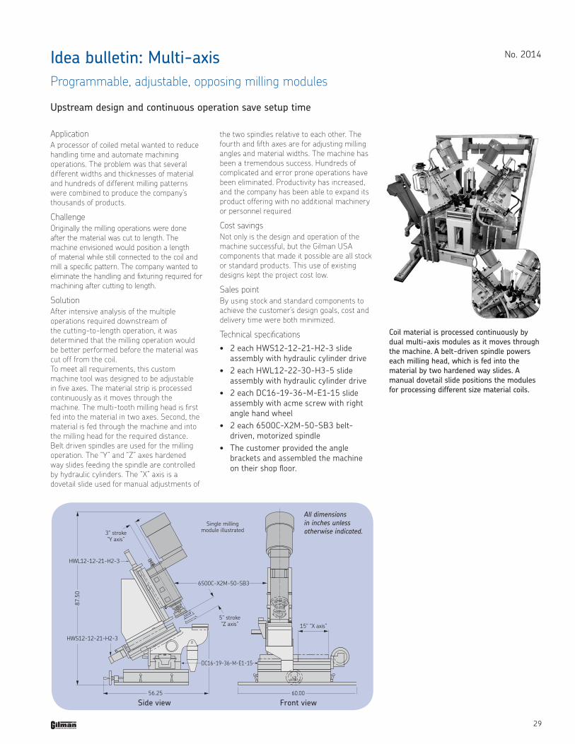
Application A processor of coiled metal wanted to reduce handling time and automate machining operations. The problem was that several different widths and thicknesses of material and hundreds of different milling patterns were combined to produce the company’s thousands of products.
ChallengeOriginally the milling operations were done after the material was cut to length. The machine envisioned would position a length of material while still connected to the coil and mill a specific pattern. The company wanted to eliminate the handling and fixturing required for machining after cutting to length.
SolutionAfter intensive analysis of the multiple operations required downstream of the cutting-to-length operation, it was determined that the milling operation would be better performed before the material was cut off from the coil. To meet all requirements, this custom machine tool was designed to be adjustable in five axes. The material strip is processed continuously as it moves through the machine. The multi-tooth milling head is first fed into the material in two axes. Second, the material is fed through the machine and into the milling head for the required distance. Belt driven spindles are used for the milling operation. The “Y” and “Z” axes hardened way slides feeding the spindle are controlled by hydraulic cylinders. The “X” axis is a dovetail slide used for manual adjustments of
No . 2014Idea bulletin: Multi-axisProgrammable, adjustable, opposing milling modules
Upstream design and continuous operation save setup time
the two spindles relative to each other. The fourth and fifth axes are for adjusting milling angles and material widths. The machine has been a tremendous success. Hundreds of complicated and error prone operations have been eliminated. Productivity has increased, and the company has been able to expand its product offering with no additional machinery or personnel required
Cost savings Not only is the design and operation of the machine successful, but the Gilman USA components that made it possible are all stock or standard products. This use of existing designs kept the project cost low.
Sales point By using stock and standard components to achieve the customer’s design goals, cost and delivery time were both minimized.
Technical specifications • 2 each HWS12-12-21-H2-3 slide
assembly with hydraulic cylinder drive• 2 each HWL12-22-30-H3-5 slide
assembly with hydraulic cylinder drive• 2 each DC16-19-36-M-E1-15 slide
assembly with acme screw with right angle hand wheel
• 2 each 6500C-X2M-50-SB3 belt-driven, motorized spindle
• The customer provided the angle brackets and assembled the machine on their shop floor .
Coil material is processed continuously by dual multi-axis modules as it moves through the machine. A belt-driven spindle powers each milling head, which is fed into the material by two hardened way slides. A manual dovetail slide positions the modules for processing different size material coils.
Side view Front view
All dimensions in inches unless otherwise indicated.

The contents of this publication are the copyright of the publisher and may not be reproduced (even extracts) unless prior written permission is granted .Every care has been taken to ensure the accuracy of the information contained in this publication but no liability can be accepted for any loss or damage whether direct, indirect or consequential arising out of use of the information contained herein .©2011 Gilman USA, LLCVersion 12/2011 Printed in U .S .A .
Gilman USA, LLC1230 Cheyenne AvenueP .O . Box 5Grafton, WI 53204Telephone: 800-445-6267 or 262-204-2227Fax: 262-377-9438e-mail: sales@GilmanUSA .comwww .gilmanusa .com