duo-chek ii valves duo-chek ii – the high performance check...
TRANSCRIPT
2 T: 936-588-4447 • F: 936-588-4427 • www.cranevalve.com
Duo-Chek® II Valves
Duo-Chek II high performance check valves are the original Mission wafer check valves introduced to the market in the late50's. They are available in the sizes, pressure classes and configurations you need to meet the most demanding of applica-tions. Our product range includes, but is not limited to,
• Sizes: 2" to 72"
• ASME Pressure Class 125 through 2500
• API 6A and 6D pressure classes
• DIN, JIS, BS, AS, and ISO standards are also available.
• Wafer, lug, double flanged and extended body styles
• Configurations available in retainerless style.
• Body Materials:
Cast Iron, Ductile Iron, WCB Cast Steel,
316 Stainless Steel. All alloys.
• Resilient Seat Materials:
EPDM, Buna-N, Neoprene,
Refrigeration-grade elastomer, Viton
• Integral and overlaid metal seats also available
• End Connections:
Raised Face, Plain Face, Ring Joint,
Weld-End, Hub-End.
Industry Standards*
API 594 Valve Design
API 598 Valve Pressure Testing & Inspection
ASME B16.5 & B16.47 Flanges
ASME B16.34 Pressure / Temperature Ratings
API 6D Pipeline Valves
API 6A Production Valves*Duo-Chek II meets or exceed these industry standards.
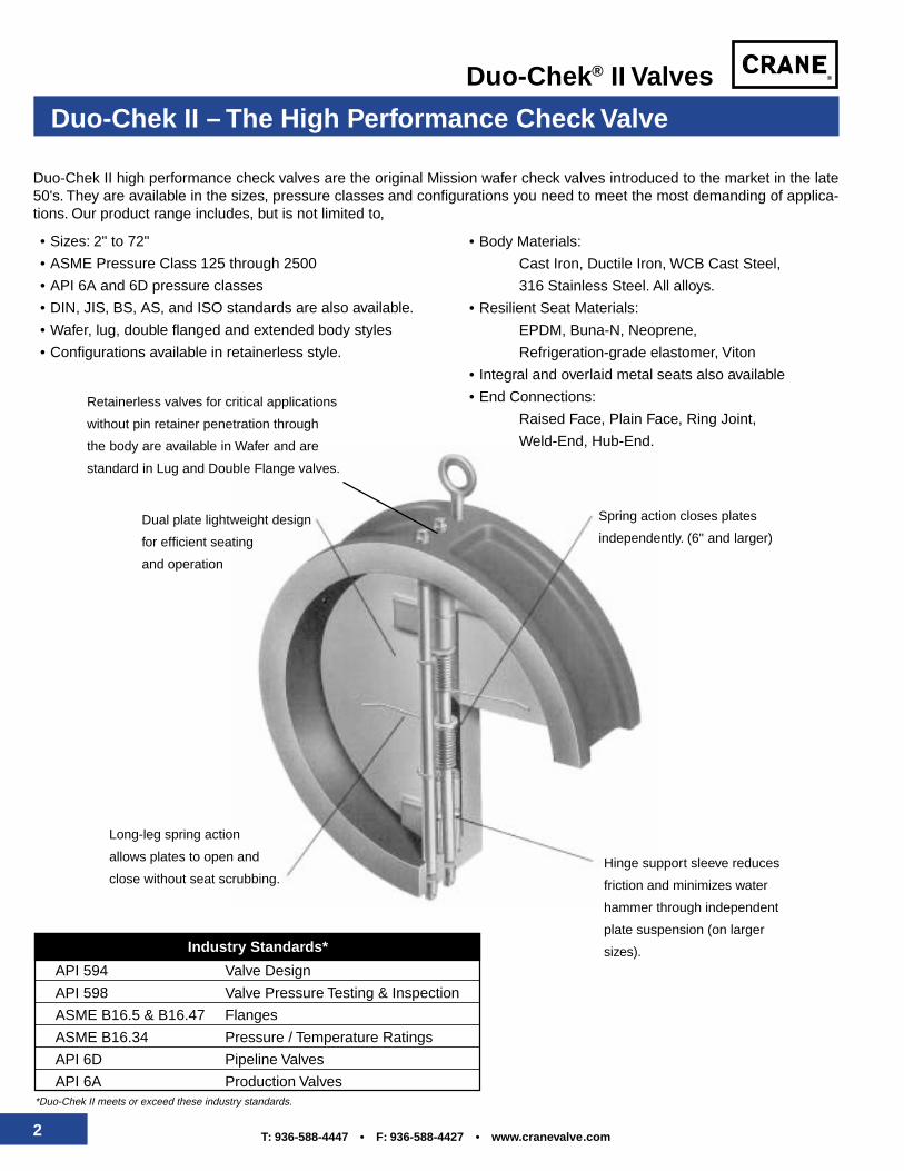
Dual plate lightweight design
for efficient seating
and operation
Long-leg spring action
allows plates to open and
close without seat scrubbing.
Spring action closes plates
independently. (6" and larger)
Hinge support sleeve reduces
friction and minimizes water
hammer through independent
plate suspension (on larger
sizes).
Duo-Chek II – The High Performance Check Valve
Retainerless valves for critical applications
without pin retainer penetration through
the body are available in Wafer and are
standard in Lug and Double Flange valves.
3T: 936-588-4447 • F: 936-588-4427 • www.cranevalve.com
Duo-Chek® II Valves
Installs between mating flanges with 10 to 20% the weight of flanged swing
checks in popular sizes - Saves money in initial valve cost and provides
lower installation cost.
Plate heel is lifted first by design to prevent seat wear. Employs two spring-
Ioaded plates with flat seats - Gives superior performance and bubble-tight
shutoff with resilient seats.
Maximum deflection of 140°, provides improved valve response and longer life -
Saves money with longer valve life and improved system performance by
reducing water hammer.
Improves valve response and reduces friction forces by 66% - Further
assurances for better performance with faster valve response.
Configuration simplifies valve insulation - Saves money.
Provides options to suit application needs - Eases your selection process by
utilizing the industry leader as your single source.
Versatility for many services - Satisfies more application needs.
Provides more rigidity than pipe, eliminating concerns of pipe bending loads of
flanged valves - Safety against thermal or seismic catastrophes.
Some sizes suitable for horizontal or vertical up positions - Simplifies piping
design, eliminates constraints that swing checks create.
For critical service applications, prevents possible escape of unwanted and/or
hazardous materials to atmosphere - Safety in critical services eliminates
and/or environmental concerns. Standards in Lug and Double Flange
Designs.
In horizontal position flow allows plates to function freely and full open under
lower flow conditions as compared to swing check - Reduces pressure loss,
improves dynamic response and eliminates valve chatter.
Wide size range, pressure range and added options allow further market needs
to be met - Reliance on world’s largest wafer check line to supply more
needs.
Features Benefits
Lightweight and Compact WaferDesign
Dual Plate, Flat Seat Design
Independent Spring Action
Independent Plate Suspensionwith Unique Hinge Design(larger sizes)
Simple, External Body Geometry
Variety of Body Designs Available- Lug and Double Flange
Wide Variety of Materials
Body Strength and Rigidity
Flexibility in Installation Position
Retainerless Duo-Chek DesignEliminates Tapped Holes in Body
Vertical Hinged Design
Special Valves Meet Market Needs:• UL/FM Listed• Rubber or Urethane Lined• Hub Ends (Grayloc®)• Weld Ends
Features and Benefits
4 T: 936-588-4447 • F: 936-588-4427 • www.cranevalve.com
Duo-Chek® II Valves
Specify the Duo-Chek II ...to your advantage
Fs
sFF
F
Spring withvalve wideopen
Unstressedspring
Plate inopenposition
Spring withvalve closed
Plate inclosed position
140°55°
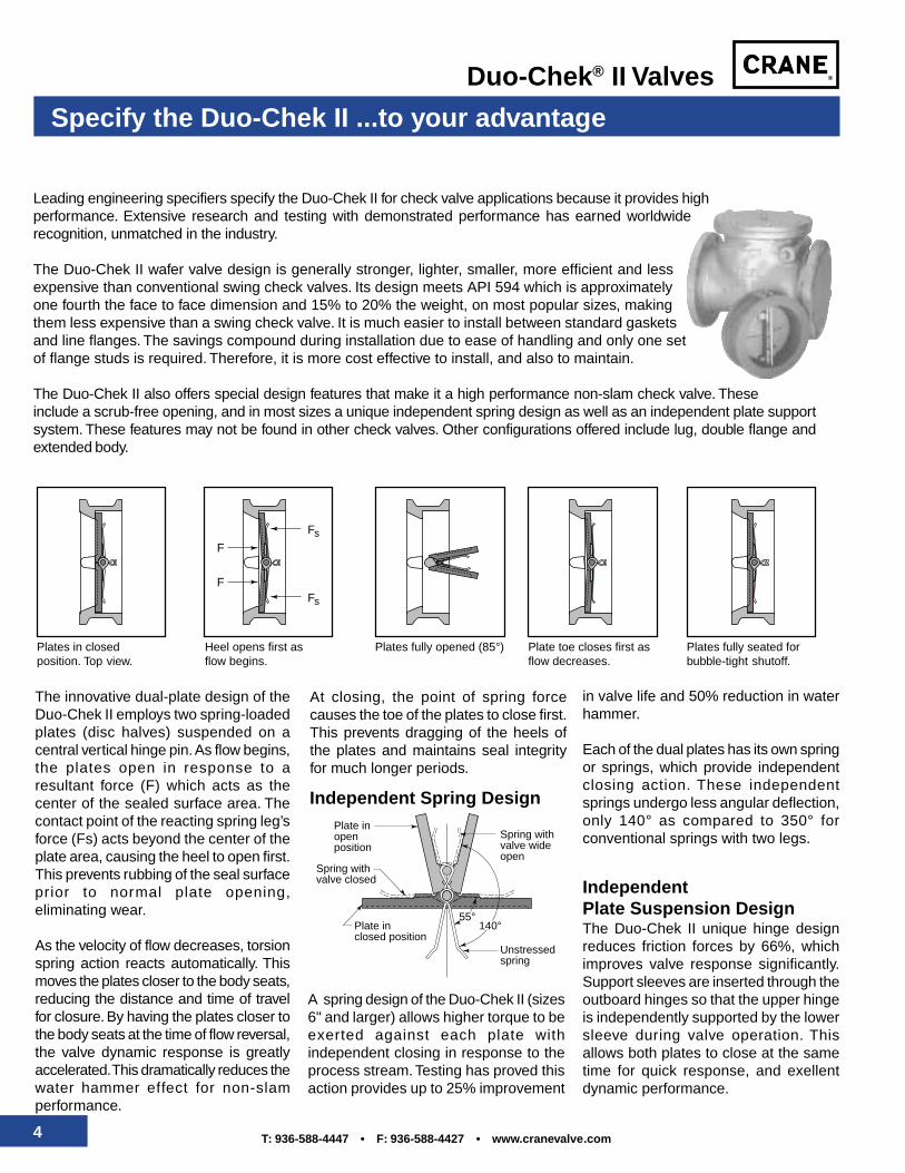
The innovative dual-plate design of theDuo-Chek II employs two spring-loadedplates (disc halves) suspended on acentral vertical hinge pin. As flow begins,the plates open in response to aresultant force (F) which acts as thecenter of the sealed surface area. Thecontact point of the reacting spring leg’sforce (Fs) acts beyond the center of theplate area, causing the heel to open first.This prevents rubbing of the seal surfaceprior to normal plate opening,eliminating wear.
As the velocity of flow decreases, torsionspring action reacts automatically. Thismoves the plates closer to the body seats,reducing the distance and time of travelfor closure. By having the plates closer tothe body seats at the time of flow reversal,the valve dynamic response is greatlyaccelerated. This dramatically reduces thewater hammer effect for non-slamperformance.
Leading engineering specifiers specify the Duo-Chek II for check valve applications because it provides highperformance. Extensive research and testing with demonstrated performance has earned worldwiderecognition, unmatched in the industry.
The Duo-Chek II wafer valve design is generally stronger, lighter, smaller, more efficient and lessexpensive than conventional swing check valves. Its design meets API 594 which is approximatelyone fourth the face to face dimension and 15% to 20% the weight, on most popular sizes, makingthem less expensive than a swing check valve. It is much easier to install between standard gasketsand line flanges. The savings compound during installation due to ease of handling and only one setof flange studs is required. Therefore, it is more cost effective to install, and also to maintain.
The Duo-Chek II also offers special design features that make it a high performance non-slam check valve. Theseinclude a scrub-free opening, and in most sizes a unique independent spring design as well as an independent plate supportsystem. These features may not be found in other check valves. Other configurations offered include lug, double flange andextended body.
Plates in closedposition. Top view.
Heel opens first asflow begins.
Plates fully opened (85°) Plate toe closes first asflow decreases.
Plates fully seated forbubble-tight shutoff.
At closing, the point of spring forcecauses the toe of the plates to close first.This prevents dragging of the heels ofthe plates and maintains seal integrityfor much longer periods.
Independent Spring Design
A spring design of the Duo-Chek II (sizes6" and larger) allows higher torque to beexerted against each plate withindependent closing in response to theprocess stream. Testing has proved thisaction provides up to 25% improvement
in valve life and 50% reduction in waterhammer.
Each of the dual plates has its own springor springs, which provide independentclosing action. These independentsprings undergo less angular deflection,only 140° as compared to 350° forconventional springs with two legs.
IndependentPlate Suspension DesignThe Duo-Chek II unique hinge designreduces friction forces by 66%, whichimproves valve response significantly.Support sleeves are inserted through theoutboard hinges so that the upper hingeis independently supported by the lowersleeve during valve operation. Thisallows both plates to close at the sametime for quick response, and exellentdynamic performance.
5T: 936-588-4447 • F: 936-588-4427 • www.cranevalve.com
Duo-Chek® II Valves
Applications
Petroleum RefiningHydrogenCrackingSteamCrude OilGasolineVisbreakersNapthaSulfur
Oil and Gas ProductionCentrifugal Compressor DischargeFire Water LinesOil/Steam SeparationSteam and CO2 InjectionGas/Oil Gathering SystemsFlowlinesWellheads
PetrochemicalsEthylenePropyleneSteamReboilersGases
ChemicalsChlorinePhosgeneAromaticsPolymersAcidsAir SeparationCaustics
Power GenerationSteamCondensateBoiler Feed PumpsCooling TowersService Water RecirculatorsRiver Water Intake
Steel/Primary MetalsQuench LinesDe-ScalingContinuous CastersSteamCondensateStrippersElectro-Galvanizing
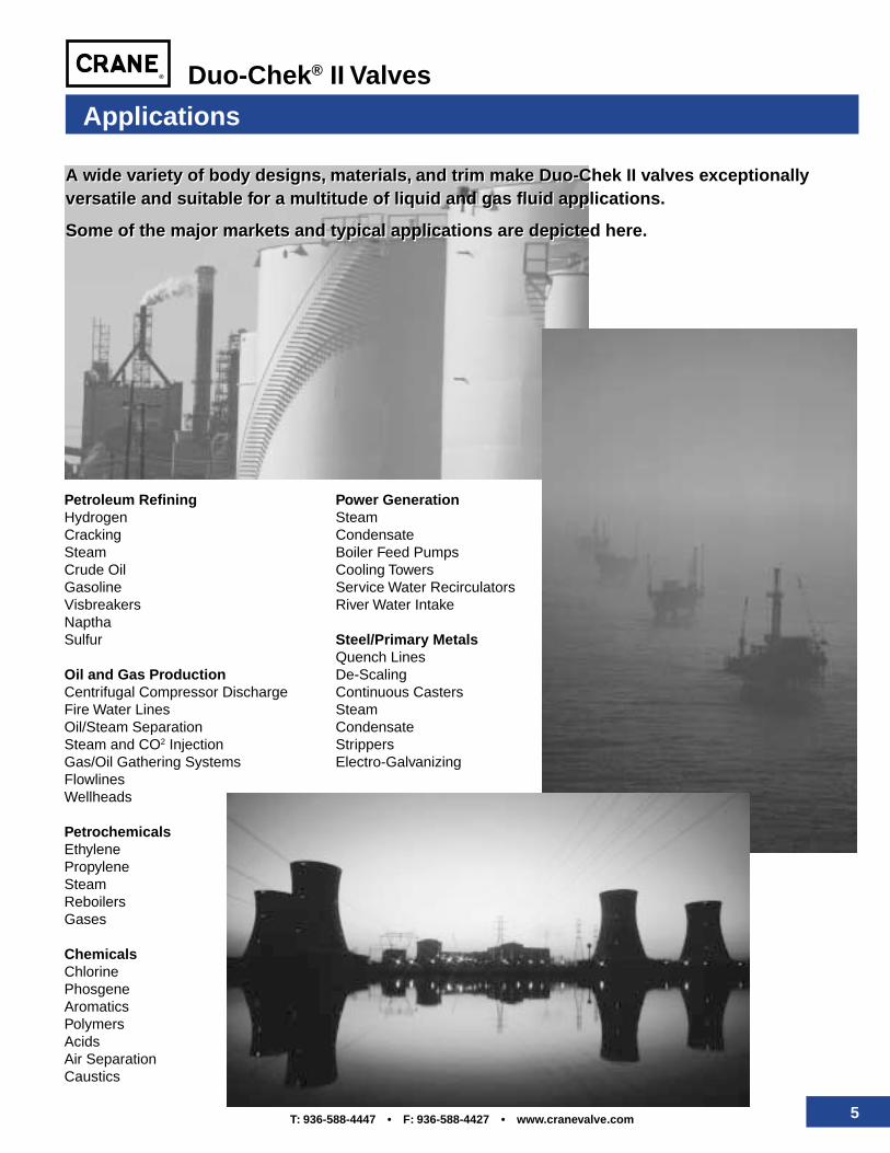
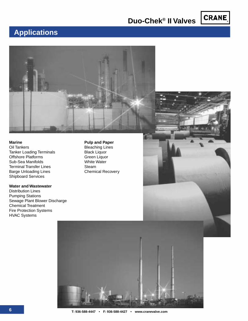
A wide variety of body designs, materials, and trim make Duo-Chek II valves exceptionallyversatile and suitable for a multitude of liquid and gas fluid applications.
Some of the major markets and typical applications are depicted here.
A wide variety of body designs, materials, and trim make Duo-Chek II valves exceptionallyversatile and suitable for a multitude of liquid and gas fluid applications.
Some of the major markets and typical applications are depicted here.
6 T: 936-588-4447 • F: 936-588-4427 • www.cranevalve.com
Duo-Chek® II Valves
Applications
MarineOil TankersTanker Loading TerminalsOffshore PlatformsSub-Sea ManifoldsTerminal Transfer LinesBarge Unloading LinesShipboard Services
Water and WastewaterDistribution LinesPumping StationsSewage Plant Blower DischargeChemical TreatmentFire Protection SystemsHVAC Systems
Pulp and PaperBleaching LinesBlack LiquorGreen LiquorWhite WaterSteamChemical Recovery
7T: 936-588-4447 • F: 936-588-4427 • www.cranevalve.com
Duo-Chek® II Valves
Valve Configurations
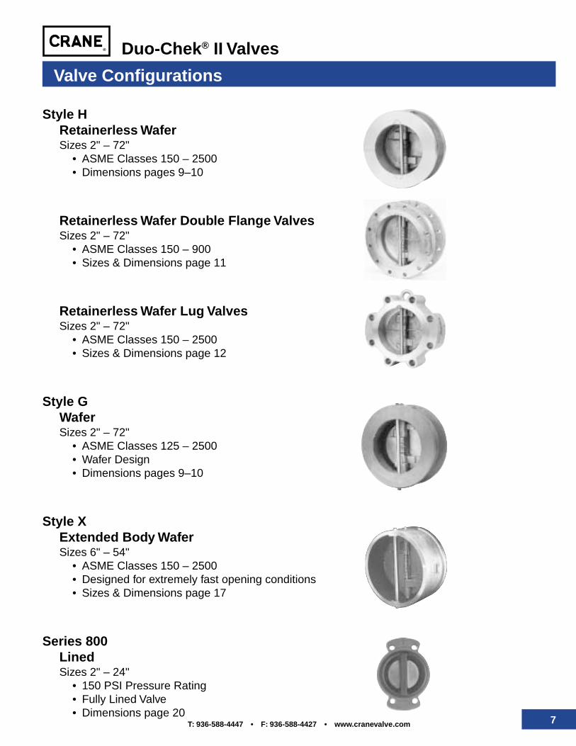
Style HRetainerless WaferSizes 2" – 72"
• ASME Classes 150 – 2500• Dimensions pages 9–10
Retainerless Wafer Double Flange ValvesSizes 2" – 72"
• ASME Classes 150 – 900• Sizes & Dimensions page 11
Retainerless Wafer Lug ValvesSizes 2" – 72"
• ASME Classes 150 – 2500• Sizes & Dimensions page 12
Style GWaferSizes 2" – 72"
• ASME Classes 125 – 2500• Wafer Design• Dimensions pages 9–10
Style XExtended Body WaferSizes 6" – 54"
• ASME Classes 150 – 2500• Designed for extremely fast opening conditions• Sizes & Dimensions page 17
Series 800LinedSizes 2" – 24"
• 150 PSI Pressure Rating• Fully Lined Valve• Dimensions page 20
8 T: 936-588-4447 • F: 936-588-4427 • www.cranevalve.com
Duo-Chek® II Valves
Style H† Retainerless Wafer Check Valves
High Performance Check Valve for Critical Applications
Because Retainerless Duo-Chek IIvalves have no body penetrationspotential leak paths through the valveare eliminated. This makes theRetainerless Duo-Chek II ideally suitedto meet the following critical serviceapplications:• Hydrocarbon processing• Chemical processing• Any industry concerned with fire
hazards or environmental safety
Key features of the Duo-Chek Style Hwafer check valve include:• A wide selection of body and plate
materials• A choice of metal-to-metal or resilient
sealing
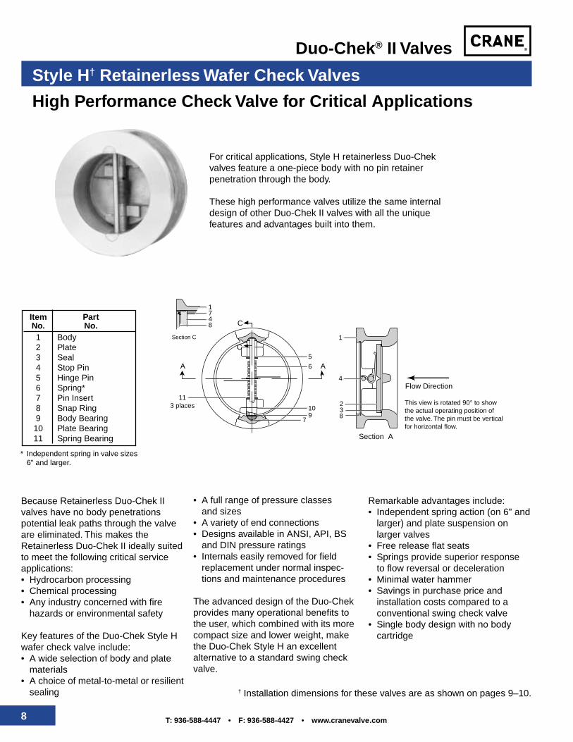
Item PartNo. No.1 Body2 Plate3 Seal4 Stop Pin5 Hinge Pin6 Spring*7 Pin Insert8 Snap Ring9 Body Bearing
10 Plate Bearing11 Spring Bearing
* Independent spring in valve sizes6" and larger.
For critical applications, Style H retainerless Duo-Chekvalves feature a one-piece body with no pin retainerpenetration through the body.
These high performance valves utilize the same internaldesign of other Duo-Chek II valves with all the uniquefeatures and advantages built into them.
• A full range of pressure classesand sizes
• A variety of end connections• Designs available in ANSI, API, BS
and DIN pressure ratings• Internals easily removed for field
replacement under normal inspec-tions and maintenance procedures
The advanced design of the Duo-Chekprovides many operational benefits tothe user, which combined with its morecompact size and lower weight, makethe Duo-Chek Style H an excellentalternative to a standard swing checkvalve.
Remarkable advantages include:• Independent spring action (on 6" and
larger) and plate suspension onlarger valves
• Free release flat seats• Springs provide superior response
to flow reversal or deceleration• Minimal water hammer• Savings in purchase price and
installation costs compared to aconventional swing check valve
• Single body design with no bodycartridge
† Installation dimensions for these valves are as shown on pages 9–10.
A
Section C
Section A
A
1
1
4
5
6
10
79
113 places
8
23
748
This view is rotated 90° to show the actual operating position of the valve. The pin must be vertical for horizontal flow.
C
C
Flow Direction
9T: 936-588-4447 • F: 936-588-4427 • www.cranevalve.com
Duo-Chek® II Valves
Size A B C D Weightin mm in mm in mm in mm in mm lbs. kg.2" 50 4 1⁄8 105 2 3⁄8 60 1 15⁄16 49 – – 6 3
2 1⁄2" 65 4 7⁄8 124 2 5⁄8 67 2 11⁄32 60 – – 10 53" 80 5 3⁄8 137 2 7⁄8 73 2 29⁄32 74 1⁄4 6 13 64" 100 6 7⁄8 175 2 7⁄8 73 3 53⁄64 97 5⁄8 16 17 85" 125 7 3⁄4 197 3 3⁄8 86 4 13⁄16 122 7⁄8 22 27 126" 150 8 3⁄4 222 3 7⁄8 98 5 49⁄64 146 1 3⁄8 35 35 168" 200 11 279 5 127 7 5⁄8 194 2 1⁄8 54 70 32
10" 250 13 3⁄8 340 5 3⁄4 146 9 9⁄16 243 2 3⁄4 70 106 4812" 300 16 1⁄8 410 7 1⁄8 181 11 3⁄8 289 3 1⁄4 83 172 7814" 350 17 3⁄4 451 7 1⁄4 184 12 1⁄2 318 3 1⁄4 83 200 9116" 400 20 1⁄4 514 7 1⁄2 191 15 381 4 7⁄16 113 275 12518" 450 21 5⁄8 549 8 203 16 7⁄8 429 5 3⁄8 137 315 14320" 500 23 7⁄8 606 8 5⁄8 219 18 13⁄16 478 6 5⁄16 160 435 19724" 600 28 1⁄4 718 8 3⁄4 222 22 5⁄8 575 8 1⁄4 210 620 28126" 650 30 1⁄2 775 14 356 24 1⁄4 616 8 203 1555 70530" 750 34 3⁄4 883 12 305 29 1⁄4 743 9 229 1230 55836" 900 41 1⁄4 1048 14 1⁄2 368 35 889 1115⁄16 303 2017 91542" 1050 48 1219 17 432 41 1041 15 381 2800 127048" 1200 54 1⁄2 1384 20 5⁄8 524 47 1194 16 3⁄4 425 3920 117854" 1350 61 1549 21 1⁄4 540 51 1⁄2 1308 19 3⁄4 502 6172 280060" 1500 67 1⁄2 1715 26 660 56 1422 – – 7800 353866" 1650 74 1⁄4 1886 31 787 65
1⁄4 1657 – – 12000 544372" 1800 80 3⁄4 2051 36 914 68 1727 – – 14000 6350
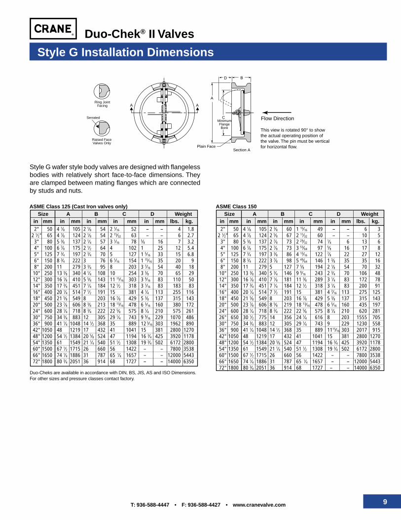
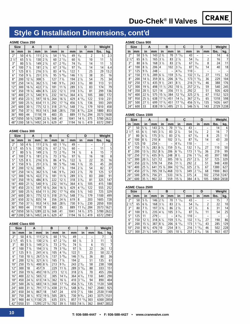
Style G Installation Dimensions
Style G wafer style body valves are designed with flangelessbodies with relatively short face-to-face dimensions. Theyare clamped between mating flanges which are connectedby studs and nuts.
Duo-Cheks are available in accordance with DIN, BS, JIS, AS and ISO Dimensions.For other sizes and pressure classes contact factory.
ASME Class 150Size A B C D Weight
in mm in mm in mm in mm in mm lbs. kg.2" 50 4 1⁄8 105 2 1⁄8 54 2 1⁄16 52 – – 4 1.8
2 1⁄2" 65 4 7⁄8 124 2 1⁄8 54 2 15⁄32 63 – – 6 2.73" 80 5 3⁄8 137 2 1⁄4 57 3 1⁄16 78 5⁄8 16 7 3.24" 100 6 7⁄8 175 2 1⁄2 64 4 102 1 25 12 5.45" 125 7 3⁄4 197 2 3⁄4 70 5 127 1 5⁄16 33 15 6.86" 150 8 3⁄4 222 3 76 6 1⁄16 154 1 15⁄16 35 20 98" 200 11 279 3 3⁄4 95 8 203 3 7⁄16 54 40 18
10" 250 13 3⁄8 340 4 1⁄4 108 10 254 3 3⁄8 70 65 2912" 300 16 1⁄8 410 5 5⁄8 143 11 15⁄16 303 3 9⁄16 83 110 5014" 350 17 3⁄4 451 7 1⁄4 184 12 1⁄2 318 3 1⁄16 83 183 8316" 400 20 1⁄4 514 7 1⁄2 191 15 381 4 1⁄4 113 255 11618" 450 21 5⁄8 549 8 203 16 7⁄8 429 5 3⁄8 137 315 14320" 500 23 7⁄8 606 8 3⁄8 213 18 13⁄16 478 6 3⁄16 160 380 17224" 600 28 1⁄4 718 8 3⁄4 222 22 5⁄8 575 8 1⁄4 210 575 26130" 750 34 3⁄4 883 12 305 29 1⁄4 743 9 9⁄16 229 1070 48636" 900 41 1⁄4 1048 14 1⁄2 368 35 889 12 5⁄16 303 1962 89042" 1050 48 1219 17 432 41 1041 15 381 2800 127048" 1200 54 1⁄2 1384 20 5⁄8 524 47 1194 16 3⁄4 425 3920 117854" 1350 61 1549 21 1⁄4 540 51 1⁄2 1308 19 3⁄4 502 6172 280060" 1500 67 1⁄2 1715 26 660 56 1422 – – 7800 353866" 1650 74 1⁄4 1886 31 787 65 1⁄4 1657 – – 12000 544372" 1800 80 3⁄4 2051 36 914 68 1727 – – 14000 6350
ASME Class 125 (Cast Iron valves only)
A
Raised FaceValves Only
Serrated
Section A
Ring JointFacing A
BD
Plain Face
A
CMinimumFlangeBore This view is rotated 90° to show
the actual operating position of the valve. The pin must be vertical for horizontal flow.
Flow Direction
10 T: 936-588-4447 • F: 936-588-4427 • www.cranevalve.com
Duo-Chek® II Valves
Style G Installation Dimensions, cont’d
Size A B C D Weightin mm in mm in mm in mm in mm lbs. kg.
2" 50 5 5⁄8 143 2 3⁄4 70 1 11⁄16 43 – – 14 62 1⁄2" 65 6 1⁄2 165 3 1⁄4 83 2 1⁄8 54 1⁄16 2 16 7
3" 80 6 5⁄8 168 3 1⁄4 83 2 5⁄8 67 5⁄16 8 24 114" 100 8 1⁄8 206 4 102 3 7⁄16 87 9⁄16 14 40 185" 125 9 3⁄4 248 – – 4 5⁄16 110 – – – –6" 150 11 3⁄8 289 6 1⁄4 159 5 3⁄16 132 1 1⁄16 27 115 528" 200 14 1⁄8 359 8 1⁄8 206 6 13⁄16 173 1 13⁄32 36 229 104
10" 250 17 1⁄8 435 9 1⁄2 241 8 1⁄2 216 1 13⁄16 46 388 17612" 300 19 5⁄8 498 11 1⁄2 292 10 1⁄8 257 2 5⁄16 59 540 24514" 350 20 1⁄2 521 14 356 11 1⁄2 292 2 51 926 42016" 400 22 5⁄8 575 15 1⁄8 384 12 13⁄16 325 2 5⁄8 67 1152 52318" 950 25 1⁄8 638 17 3⁄4 451 14 7⁄16 367 2 9⁄16 65 1318 59820" 500 27 1⁄2 699 17 3⁄4 451 17 15⁄16 456 5 5⁄16 135 1426 64724" 600 33 838 19 1⁄2 495 21 1⁄2 546 5 5⁄8 143 2729 1238
Size A B C D Weightin mm in mm in mm in mm in mm lbs. kg.2" 50 4 3⁄8 111 2 3⁄8 60 1 15⁄16 49 – – 7 3
2 1⁄2" 65 5 1⁄8 130 2 5⁄8 67 2 11⁄32 60 – – 11 53" 80 5 7⁄8 149 2 7⁄8 73 2 29⁄32 74 1⁄4 6 15 74" 100 7 1⁄8 181 2 7⁄8 73 3 53⁄64 97 5⁄8 16 18 85" 125 8 1⁄2 216 3 3⁄8 86 4 13⁄16 122 7⁄8 22 35 166" 150 9 7⁄8 251 3 7⁄8 98 5 49⁄64 146 1 3⁄8 35 45 208" 200 12 1⁄8 308 5 127 7 5⁄8 194 2 1⁄8 54 82 37
10" 250 14 1⁄4 362 5 3⁄4 146 9 9⁄16 243 2 3⁄4 70 125 5712" 300 16 5⁄8 422 7 1⁄8 181 11 3⁄8 289 3 1⁄4 83 200 9114" 350 19 1⁄8 486 8 3⁄4 222 12 1⁄2 318 3 3⁄16 81 325 14716" 400 21 1⁄4 540 9 1⁄8 232 14 5⁄16 364 4 1⁄8 105 415 18818" 450 23 1⁄2 597 10 3⁄8 264 16 7⁄8 429 4 13⁄16 122 555 25220" 500 25 3⁄4 654 11 1⁄2 292 17 15⁄16 456 5 5⁄8 143 725 32924" 600 30 1⁄2 775 12 1⁄2 318 21 9⁄16 548 7 1⁄16 179 1100 49926" 650 32 7⁄8 835 14 356 24 3⁄8 619 8 203 1605 72830" 750 37 1⁄2 953 14
1⁄2 368 28 3⁄4 730 9 1⁄16 230 2050 930
36" 900 44 1118 19 483 35 889 11 3⁄16 284 3573 162142" 1050 50 3⁄4 1289 22 3⁄8 568 41 1041 14 3⁄4 375 5780 262248" 1200 58 3⁄4 1492 24 3⁄4 629 47 1194 16 1⁄2 419 6572 2981
2" 50 5 5⁄8 143 2 3⁄4 70 1 11⁄16 43 – – 14 62 1⁄2" 65 6 1⁄2 165 3 1⁄4 83 2 1⁄8 54 1⁄16 2 16 7
3" 80 6 7⁄8 175 3 1⁄4 83 2 5⁄8 67 5⁄16 8 25 114" 100 8 1⁄4 210 4 102 3 7⁄16 87 9⁄16 14 43 205" 125 10 254 – – 4 5⁄16 110 – – – –6" 150 11 1⁄8 283 6 1⁄4 159 5 3⁄16 132 1 1⁄16 27 110 508" 200 13 7⁄8 352 8 1⁄8 206 6 13⁄16 173 1 13⁄32 36 219 9910" 250 17 1⁄8 435 9 3⁄4 248 8 1⁄2 216 1 11⁄16 43 397 18012" 300 20 1⁄2 521 12 305 10 1⁄8 257 2 1⁄4 57 725 32914" 350 22 3⁄4 578 14 356 11 1⁄2 292 2 51 948 43016" 400 25 1⁄4 641 15 1⁄8 384 12 13⁄16 325 2 5⁄8 67 1380 62718" 450 27 3⁄4 705 18 7⁄16 468 13 3⁄4 349 2 11⁄16 68 1900 86320" 500 29 3⁄4 756 21 533 14 3⁄4 375 4 102 2750 124724" 600 35 1⁄2 902 22 559 15 1⁄8 384 4 1⁄8 105 5860 2658
2" 50 4 3⁄8 111 2 3⁄8 60 1 15⁄16 49 – – 7 32 1⁄2" 65 5 1⁄8 130 2 5⁄8 67 2 11⁄32 60 1⁄8 3 11 5
3" 80 5 7⁄8 149 2 7⁄8 73 2 29⁄32 74 1⁄4 6 15 74" 100 7 5⁄8 194 3 1⁄8 79 3 53⁄64 97 7⁄8 22 26 125" 125 9 1⁄2 241 4 1⁄8 105 4 13⁄16 122 1 25 50 22.76" 150 10 1⁄2 267 5 3⁄8 137 5 49⁄64 146 1 7⁄16 36 80 368" 200 12 5⁄8 321 6 1⁄2 165 7 5⁄8 194 2 51 135 61
10" 250 15 3⁄4 400 8 3⁄8 213 9 9⁄16 243 2 9⁄32 58 238 10812" 300 18 457 9 229 11 3⁄8 289 3 15⁄32 88 333 15114" 350 19 3⁄8 492 10 3⁄4 273 12 1⁄2 318 2 3⁄4 70 455 20616" 400 22 1⁄4 565 12 305 14 5⁄16 364 4 5⁄16 110 640 29018" 450 24 1⁄8 613 14 1⁄4 362 16 1⁄8 410 3 11⁄16 94 890 40420" 500 26 7⁄8 683 14 1⁄2 368 17 15⁄16 456 5 5⁄16 135 1120 50824" 600 31 1⁄8 791 17 1⁄4 438 21 9⁄16 548 6 9⁄16 167 2040 92526" 650 34 1⁄8 867 18 547 24 610 7 1⁄4 184 2530 114830" 750 38 1⁄4 972 19
7⁄8 505 28 3⁄4 730 9 9⁄16 243 3375 1531
36" 900 44 1⁄2 1130 25 635 33 3⁄4 857 11 15⁄16 303 6300 2858
42" 1050 51 1295 27 5⁄8 702 39 1⁄2 1003 14 1⁄4 362 8447 3832
ASME Class 300
ASME Class 600
ASME Class 900
ASME Class 1500
ASME Class 2500
2" 50 5 3⁄4 146 2 3⁄4 70 1 11⁄16 43 – – 15 72 1⁄2" 65 6 5⁄8 168 3 1⁄4 83 2 1⁄8 54 1⁄16 2 22 103" 80 7 3⁄4 197 3 3⁄8 86 2 5⁄8 67 1⁄4 6 31 144" 100 9 1⁄4 235 4 1⁄8 105 3 7⁄16 87 7⁄16 11 54 255" 125 11 279 – – 4 5⁄16 110 – – – –6" 150 12 1⁄2 318 6 1⁄4 159 5 3⁄16 132 1 1⁄16 27 190 868" 200 15 1⁄4 387 8 1⁄8 206 6 13⁄16 173 1 11⁄16 43 285 12910" 250 18 3⁄4 476 10 254 8 1⁄2 216 1 13⁄16 46 502 22812" 300 21 5⁄8 549 12 305 10 1⁄8 257 2 3⁄16 56 963 437
Size A B C D Weightin mm in mm in mm in mm in mm lbs. kg.
Size A B C D Weightin mm in mm in mm in mm in mm lbs. kg.
Size A B C D Weightin mm in mm in mm in mm in mm lbs. kg.
Size A B C D Weightin mm in mm in mm in mm in mm lbs. kg.2" 50 4 3⁄8 111 2 1⁄8 54 1 15⁄16 49 3⁄32 2 5 2.3
2 1⁄2" 65 5 1⁄8 130 2 3⁄8 60 2 11⁄32 60 3⁄8 10 11 53" 80 5 7⁄8 149 2 5⁄8 67 2 29⁄32 74 9⁄16 14 11 54" 100 7 1⁄8 181 2 5⁄8 67 3 53⁄64 97 9⁄16 14 14 6.45" 125 8 1⁄2 216 3 1⁄4 83 4 13⁄16 122 1 25 29 13.26" 150 9 7⁄8 251 3 3⁄4 95 5 49⁄64 146 1 1⁄2 38 35 168" 200 12 1⁄8 308 5 127 7 5⁄8 194 2 1⁄8 54 75 3410" 250 14 1⁄4 362 5 1⁄2 140 9 9⁄16 243 3 1⁄16 80 113 5112" 300 16 5⁄8 422 7 1⁄8 181 11 3⁄8 289 3 1⁄4 83 174 7914" 350 19 1⁄8 486 8 3⁄4 222 12 1⁄2 318 3 3⁄16 81 299 13616" 400 21 1⁄4 540 9 1⁄8 232 14 5⁄16 364 4 1⁄8 105 380 17218" 450 23 1⁄2 597 10 3⁄8 264 16 7⁄8 429 4 13⁄16 122 510 23120" 500 25 3⁄4 654 11 1⁄2 292 17 15⁄16 456 5 3⁄8 136 593 26924" 600 30 1⁄2 775 12 1⁄2 318 21 9⁄16 548 7 1⁄16 179 1010 45830" 750 37 1⁄2 953 14
1⁄2 368 28 3⁄4 730 8 13⁄16 224 1880 853
36" 900 44 1118 19 483 35 889 11 9⁄16 294 3573 160842" 1050 50 3⁄4 1289 22 3⁄8 568 41 1041 14 3⁄4 375 5780 262248" 1200 58 3⁄4 1492 24 3⁄4 629 47 1194 16 1⁄2 419 6572 2981
ASME Class 250
11T: 936-588-4447 • F: 936-588-4427 • www.cranevalve.com
Duo-Chek® II Valves
CA
B
Pin must be verticalfor horizontal flow. Flow Direction
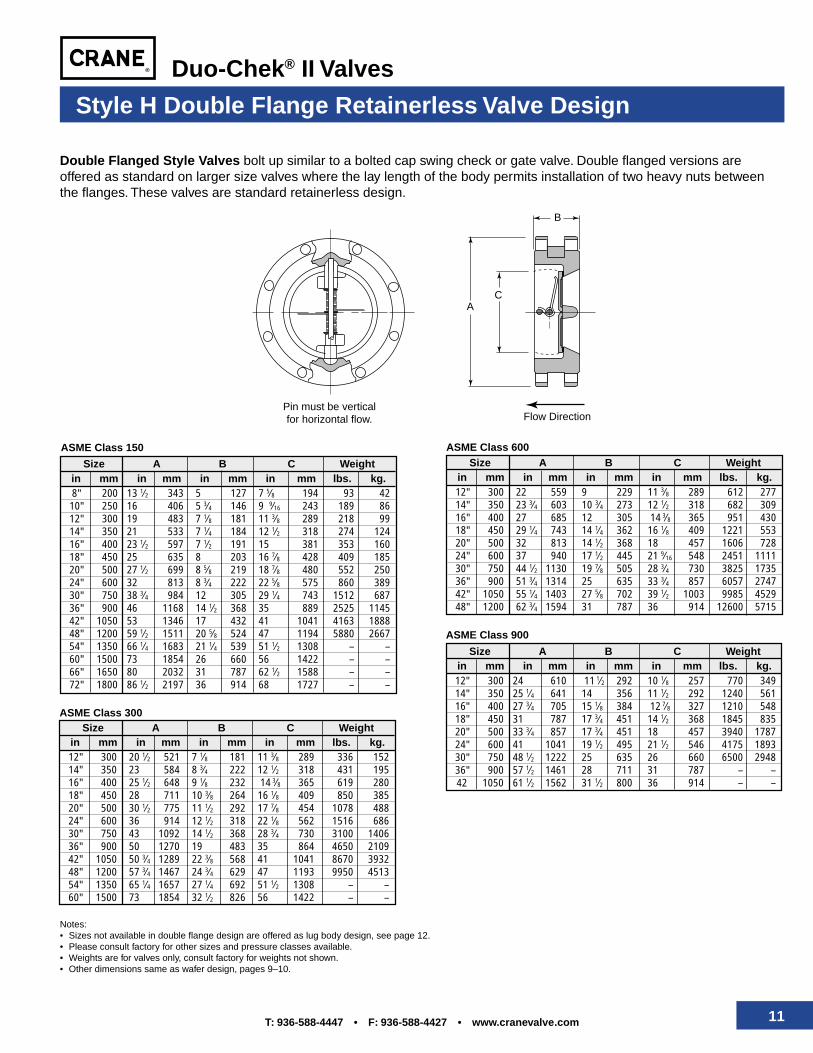
Double Flanged Style Valves bolt up similar to a bolted cap swing check or gate valve. Double flanged versions areoffered as standard on larger size valves where the lay length of the body permits installation of two heavy nuts betweenthe flanges. These valves are standard retainerless design.
Style H Double Flange Retainerless Valve Design
ASME Class 150
ASME Class 300
ASME Class 900
Notes:• Sizes not available in double flange design are offered as lug body design, see page 12.• Please consult factory for other sizes and pressure classes available.• Weights are for valves only, consult factory for weights not shown.• Other dimensions same as wafer design, pages 9–10.
Size A B C Weightin mm in mm in mm in mm lbs. kg.12" 300 20 1⁄2 521 7 1⁄8 181 11 3⁄8 289 336 15214" 350 23 584 8 3⁄4 222 12 1⁄2 318 431 19516" 400 25 1⁄2 648 9 1⁄8 232 14 3⁄8 365 619 28018" 450 28 711 10 3⁄8 264 16 1⁄8 409 850 38520" 500 30 1⁄2 775 11 1⁄2 292 17 7⁄8 454 1078 48824" 600 36 914 12 1⁄2 318 22 1⁄8 562 1516 68630" 750 43 1092 14 1⁄2 368 28 3⁄4 730 3100 140636" 900 50 1270 19 483 35 864 4650 210942" 1050 50 3⁄4 1289 22 3⁄8 568 41 1041 8670 393248" 1200 57 3⁄4 1467 24 3⁄4 629 47 1193 9950 451354" 1350 65 1⁄4 1657 27 1⁄4 692 51 1⁄2 1308 – –60" 1500 73 1854 32 1⁄2 826 56 1422 – –
Size A B C Weightin mm in mm in mm in mm lbs. kg.8" 200 13 1⁄2 343 5 127 7 5⁄8 194 93 4210" 250 16 406 5 3⁄4 146 9 9⁄16 243 189 8612" 300 19 483 7 1⁄8 181 11 3⁄8 289 218 9914" 350 21 533 7 1⁄4 184 12 1⁄2 318 274 12416" 400 23 1⁄2 597 7 1⁄2 191 15 381 353 16018" 450 25 635 8 203 16 7⁄8 428 409 18520" 500 27 1⁄2 699 8 5⁄8 219 18 7⁄8 480 552 25024" 600 32 813 8 3⁄4 222 22 5⁄8 575 860 38930" 750 38 3⁄4 984 12 305 29 1⁄4 743 1512 68736" 900 46 1168 14 1⁄2 368 35 889 2525 114542" 1050 53 1346 17 432 41 1041 4163 188848" 1200 59 1⁄2 1511 20 5⁄8 524 47 1194 5880 266754" 1350 66 1⁄4 1683 21 1⁄4 539 51 1⁄2 1308 – –60" 1500 73 1854 26 660 56 1422 – –66" 1650 80 2032 31 787 62 1⁄2 1588 – –72" 1800 86 1⁄2 2197 36 914 68 1727 – –
Size A B C Weightin mm in mm in mm in mm lbs. kg.12" 300 24 610 11 1⁄2 292 10 1⁄8 257 770 34914" 350 25 1⁄4 641 14 356 11 1⁄2 292 1240 56116" 400 27 3⁄4 705 15 1⁄8 384 12 7⁄8 327 1210 54818" 450 31 787 17 3⁄4 451 14 1⁄2 368 1845 83520" 500 33 3⁄4 857 17 3⁄4 451 18 457 3940 178724" 600 41 1041 19 1⁄2 495 21 1⁄2 546 4175 189330" 750 48 1⁄2 1222 25 635 26 660 6500 294836" 900 57 1⁄2 1461 28 711 31 787 – –42 1050 61 1⁄2 1562 31 1⁄2 800 36 914 – –
ASME Class 600Size A B C Weight
in mm in mm in mm in mm lbs. kg.12" 300 22 559 9 229 11 3⁄8 289 612 27714" 350 23 3⁄4 603 10 3⁄4 273 12 1⁄2 318 682 30916" 400 27 685 12 305 14 3⁄8 365 951 43018" 450 29 1⁄4 743 14 1⁄4 362 16 1⁄8 409 1221 55320" 500 32 813 14 1⁄2 368 18 457 1606 72824" 600 37 940 17 1⁄2 445 21 9⁄16 548 2451 111130" 750 44 1⁄2 1130 19 7⁄8 505 28 3⁄4 730 3825 173536" 900 51 3⁄4 1314 25 635 33 3⁄4 857 6057 274742" 1050 55 1⁄4 1403 27 5⁄8 702 39 1⁄2 1003 9985 452948" 1200 62 3⁄4 1594 31 787 36 914 12600 5715
12 T: 936-588-4447 • F: 936-588-4427 • www.cranevalve.com
Duo-Chek® II Valves
Full BodyScallop
Pin must be verticalfor horizontal flow.
CA
B
Threaded
Thru hole
Flow Direction
2" 50 6 1⁄2 165 2 3⁄8 60 1 15⁄16 49 18 82 1⁄2" 65 7 1⁄2 191 2 5⁄8 67 2 11⁄32 60 22 103" 80 8 1⁄4 210 2 7⁄8 73 2 29⁄32 74 30 144" 100 10 3⁄4 273 3 1⁄8 79 3 53⁄64 97 50 236" 150 14 356 5 3⁄8 137 5 49⁄64 146 183 838" 200 16 1⁄2 419 6 1⁄2 165 7 5⁄8 194 295 13410" 250 20 508 8 3⁄8 213 9 9⁄16 243 540 245
Size A B C Weightin mm in mm in mm in mm lbs. kg.
ASME Class 600
2" 50 81⁄2 216 23⁄4 70 111⁄16 43 37 173" 80 91⁄2 241 31⁄4 83 25⁄8 67 57 264" 100 111⁄2 292 4 102 37⁄16 87 98 456" 150 15 381 61⁄4 159 53⁄16 132 252 1148" 200 181⁄2 470 81⁄8 206 613⁄16 173 441 200
10" 250 211⁄2 546 91⁄2 241 81⁄2 216 787 357
Size A B C Weightin mm in mm in mm in mm lbs. kg.
ASME Class 900
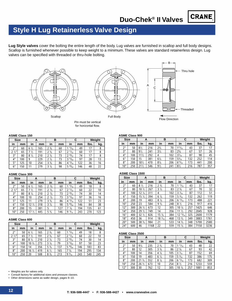
Lug Style valves cover the bolting the entire length of the body. Lug valves are furnished in scallop and full body designs.Scallop is furnished whenever possible to keep weight to a minimum. These valves are standard retainerless design. Lugvalves can be specified with threaded or thru-hole bolting.
Style H Lug Retainerless Valve Design
2" 60 6 1⁄2 165 2 3⁄8 60 1 15⁄16 49 17 82 1⁄2" 65 7 1⁄2 191 2 5⁄8 67 2 11⁄32 60 17 83" 80 8 1⁄4 210 2 7⁄8 73 2 29⁄32 74 17 84" 100 9 229 2 7⁄8 73 3 53⁄64 97 28 135" 125 10 254 3 3⁄8 86 4 13⁄16 122 36 166" 150 11 279 3 7⁄8 98 5 49⁄64 146 48 22
Size A B C Weightin mm in mm in mm in mm lbs. kg.
ASME Class 150
Size A B C Weightin mm in mm in mm in mm lbs. kg.
ASME Class 300
2" 50 6 1⁄2 165 2 3⁄8 60 1 15⁄16 49 18 82 1⁄2" 65 7 1⁄2 191 2 5⁄8 67 2 11⁄32 60 22 10
3" 80 8 1⁄4 210 2 7⁄8 73 2 29⁄32 74 30 144" 100 10 254 2 7⁄8 73 3 53⁄64 97 36 165" 125 11 279 3 3⁄8 86 4 13⁄16 122 51 236" 150 12 1⁄2 318 3 7⁄8 98 5 49⁄64 146 84 388" 200 15 381 5 127 7 5⁄8 194 135 61
10" 250 17 1⁄2 445 5 3⁄4 146 9 9⁄16 243 270 123
2" 60 8 1⁄2 216 2 3⁄4 70 1 11⁄16 43 37 173" 80 10 1⁄2 267 3 1⁄4 83 2 5⁄8 67 70 324" 100 12 1⁄4 311 4 102 3 7⁄16 87 112 516" 150 15 1⁄2 394 6 1⁄4 159 5 3⁄16 132 262 1198" 200 19 483 8 1⁄8 206 6 13⁄16 173 488 221
10" 250 23 584 9 3⁄4 248 8 1⁄2 216 917 41612" 300 26 1⁄2 673 12 305 10 1⁄8 257 1425 64614" 350 29 1⁄2 749 14 356 11 1⁄2 292 2045 92816" 400 32 1⁄2 826 15 1⁄8 384 12 13⁄16 325 2600 117918" 450 36 914 18 7⁄16 468 13 3⁄4 349 3883 176120" 500 38 3⁄4 984 21 533 14 3⁄4 348 5700 258024" 600 46 1168 22 559 15 1⁄8 384 7150 3236
Size A B C Weightin mm in mm in mm in mm lbs. kg.
ASME Class 1500
2" 50 91⁄4 235 2 3⁄4 70 1 11⁄16 43 48 223" 80 12 305 3 3⁄8 86 2 5⁄8 67 93 424" 100 14 356 4 1⁄8 105 3 7⁄16 87 152 696" 150 19 483 6 1⁄4 159 5 3⁄16 132 386 1758" 200 21 3⁄4 552 8 1⁄8 206 6 13⁄16 173 682 309
10" 250 26 1⁄2 673 10 254 8 1⁄2 216 1233 55912" 300 30 762 12 305 10 1⁄8 257 1881 853
Size A B C Weightin mm in mm in mm in mm lbs. kg.
ASME Class 2500
• Weights are for valves only.• Consult factory for additional sizes and pressure classes.• Other dimensions same as wafer design, pages 9–10.
13T: 936-588-4447 • F: 936-588-4427 • www.cranevalve.com
Duo-Chek® II Valves
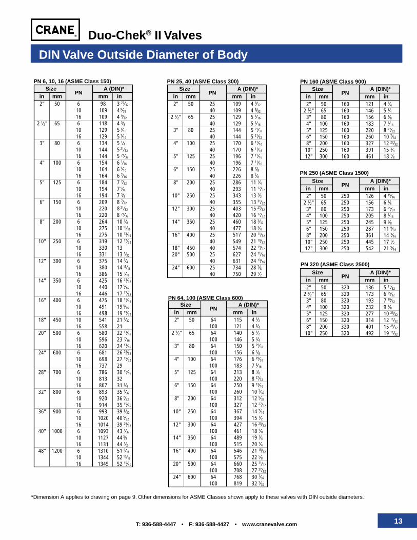
PN 6, 10, 16 (ASME Class 150)
DIN Valve Outside Diameter of Body
PN 25, 40 (ASME Class 300)
PN 64, 100 (ASME Class 600)
PN 160 (ASME Class 900)Size
PNA (DIN)*
in mm mm in2" 50 160 121 4 3⁄4
2 1⁄2" 65 160 146 5 3⁄43" 80 160 156 6 1⁄84" 100 160 183 7 3⁄16
5" 125 160 220 8 27⁄32
6" 150 160 260 10 7⁄32
8" 200 160 327 12 27⁄32
10" 250 160 391 15 3⁄812" 300 160 461 18 1⁄8
PN 250 (ASME Class 1500)Size
PNA (DIN)*
in mm mm in2" 50 250 126 4 15⁄16
2 1⁄2" 65 250 156 6 1⁄83" 80 250 173 6 25⁄32
4" 100 250 205 8 1⁄16
5" 125 250 245 9 5⁄86" 150 250 287 11 9⁄32
8" 200 250 361 14 3⁄16
10" 250 250 445 17 1⁄212" 300 250 542 21 5⁄16
PN 320 (ASME Class 2500)Size
PNA (DIN)*
in mm mm in2" 50 320 136 5 11⁄32
2 1⁄2" 65 320 173 6 25⁄32
3" 80 320 193 7 19⁄32
4" 100 320 232 9 1⁄85" 125 320 277 10 29⁄32
6" 150 320 314 12 11⁄32
8" 200 320 401 15 25⁄32
10" 250 320 492 19 11⁄32
*Dimension A applies to drawing on page 9. Other dimensions for ASME Classes shown apply to these valves with DIN outside diameters.
SizePN
A (DIN)*in mm mm in2" 50 64 115 4 1⁄2
100 121 4 3⁄42 1⁄2" 65 64 140 5 1⁄2
100 146 5 3⁄43" 80 64 150 5 29⁄32
100 156 6 1⁄84" 100 64 176 6 29⁄32
100 183 7 3⁄16
5" 125 64 213 8 3⁄8100 220 8 27⁄32
6" 150 64 250 9 13⁄16
100 260 10 7⁄32
8" 200 64 312 12 9⁄32
100 327 12 27⁄32
10" 250 64 367 14 7⁄16
100 394 15 1⁄212" 300 64 427 16 25⁄32
100 461 18 1⁄814" 350 64 489 19 1⁄4
100 515 20 1⁄416" 400 64 546 21 15⁄32
100 575 22 5⁄820" 500 64 660 25 31⁄32
100 708 27 27⁄32
24" 600 64 768 30 7⁄32
100 819 32 7⁄32
SizePN
A (DIN)*in mm mm in2" 50 6 98 3 27⁄32
10 109 4 9⁄32
16 109 4 9⁄32
2 1⁄2" 65 6 118 4 5⁄810 129 5
1⁄16
16 129 5 1⁄16
3" 80 6 134 5 1⁄410 144 5
21⁄32
16 144 5 21⁄32
4" 100 6 154 6 1⁄16
10 164 6 7⁄16
16 164 6 7⁄16
5" 125 6 184 7 7⁄32
10 194 7 5⁄8
16 194 7 5⁄86" 150 6 209 8 7⁄32
10 220 8 21⁄32
16 220 8 21⁄32
8" 200 6 264 10 3⁄810 275 10
13⁄16
16 275 10 13⁄16
10" 250 6 319 12 17⁄32
10 330 1316 331 13 1⁄32
12" 300 6 375 14 3⁄410 380 14
15⁄16
16 386 15 3⁄16
14" 350 6 425 16 23⁄32
10 440 17 5⁄16
16 446 17 17⁄32
16" 400 6 475 18 11⁄16
10 491 19 5⁄16
16 498 19 19⁄32
18" 450 10 541 21 9⁄32
16 558 2120" 500 6 580 22 13⁄16
10 596 23 7⁄16
16 620 24 13⁄16
24" 600 6 681 26 25⁄32
10 698 27 15⁄32
16 737 2928" 700 6 786 30 15⁄16
10 813 3216 807 31 3⁄4
32" 800 6 893 35 5⁄32
10 920 36 7⁄32
16 914 35 15⁄16
36" 900 6 993 39 3⁄32
10 1020 40 5⁄32
16 1014 39 29⁄32
40" 1000 6 1093 43 1⁄32
10 1127 44 3⁄8
16 1131 44 1⁄248" 1200 6 1310 51 9⁄16
10 1344 52 15⁄16
16 1345 52 15⁄16
SizePN
A (DIN)*in mm mm in2" 50 25 109 4 9⁄32
40 109 4 9⁄32
2 1⁄2" 65 25 129 5 1⁄16
40 129 5 1⁄16
3" 80 25 144 5 21⁄32
40 144 5 21⁄32
4" 100 25 170 6 11⁄16
40 170 6 11⁄16
5" 125 25 196 7 11⁄16
40 196 7 11⁄16
6" 150 25 226 8 7⁄840 226 8 7⁄8
8" 200 25 286 11 1⁄440 293 11 17⁄32
10" 250 25 343 13 1⁄240 355 13 31⁄32
12" 300 25 403 15 27⁄32
40 420 16 17⁄32
14" 350 25 460 18 3⁄32
40 477 18 3⁄416" 400 25 517 20 11⁄32
40 549 21 19⁄32
18" 450 40 574 22 19⁄32
20" 500 25 627 24 11⁄16
40 631 24 13⁄16
24" 600 25 734 28 7⁄840 750 29 1⁄2
14 T: 936-588-4447 • F: 936-588-4427 • www.cranevalve.com
Duo-Chek® II Valves
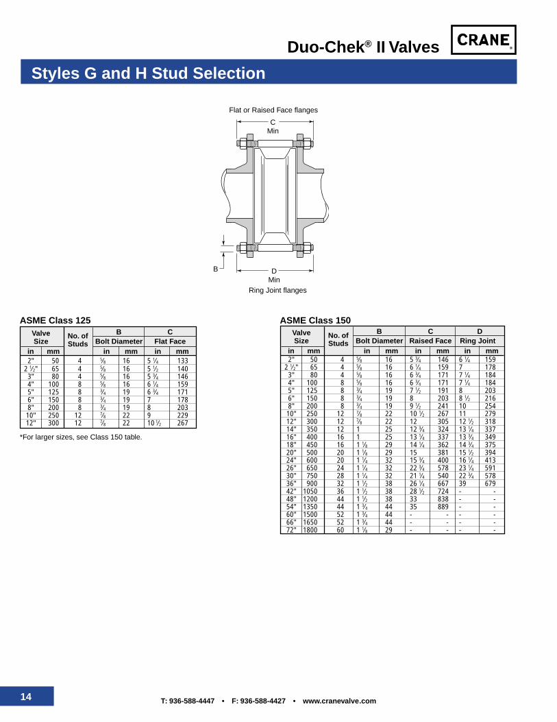
Styles G and H Stud Selection
2" 50 4 5⁄8 16 5 3⁄4 146 6 1⁄4 1592 1⁄2" 65 4 5⁄8 16 6 1⁄4 159 7 1783" 80 4 5⁄8 16 6 3⁄4 171 7 1⁄4 1844" 100 8 5⁄8 16 6 3⁄4 171 7 1⁄4 1845" 125 8 3⁄4 19 7 1⁄2 191 8 2036" 150 8 3⁄4 19 8 203 8 1⁄2 2168" 200 8 3⁄4 19 9 1⁄2 241 10 25410" 250 12 7⁄8 22 10 1⁄2 267 11 27912" 300 12 7⁄8 22 12 305 12 1⁄2 31814" 350 12 1 25 12 3⁄4 324 13 1⁄4 33716" 400 16 1 25 13 1⁄4 337 13 3⁄4 34918" 450 16 1 1⁄8 29 14 1⁄4 362 14 3⁄4 37520" 500 20 1 1⁄8 29 15 381 15 1⁄2 39424" 600 20 1 1⁄4 32 15 3⁄4 400 16 1⁄4 41326" 650 24 1 1⁄4 32 22 3⁄4 578 23 1⁄4 59130" 750 28 1 1⁄4 32 21 1⁄4 540 22 3⁄4 57836" 900 32 1 1⁄2 38 26 1⁄4 667 39 67942" 1050 36 1 1⁄2 38 28 1⁄2 724 - -48" 1200 44 1 1⁄2 38 33 838 - -54" 1350 44 1 3⁄4 44 35 889 - -60" 1500 52 1 3⁄4 44 - - - -66" 1650 52 1 3⁄4 44 - - - -72" 1800 60 1 1⁄8 29 - - - -
Valve No. of B C DSize Studs Bolt Diameter Raised Face Ring Joint
in mm in mm in mm in mm
ASME Class 150
2" 50 4 5⁄8 16 5 1⁄4 1332 1⁄2" 65 4 5⁄8 16 5 1⁄2 1403" 80 4 5⁄8 16 5 3⁄4 1464" 100 8 5⁄8 16 6 1⁄4 1595" 125 8 3⁄4 19 6 3⁄4 1716" 150 8 3⁄4 19 7 1788" 200 8 3⁄4 19 8 20310" 250 12 7⁄8 22 9 22912" 300 12 7⁄8 22 10 1⁄2 267
Valve No. of B CSize Studs Bolt Diameter Flat Face
in mm in mm in mm
ASME Class 125
*For larger sizes, see Class 150 table.
B
CMin
DMin
Flat or Raised Face flanges
Ring Joint flanges
15T: 936-588-4447 • F: 936-588-4427 • www.cranevalve.com
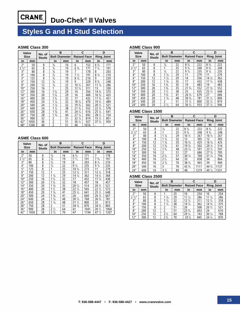
Duo-Chek® II Valves
2" 50 8 5⁄8 16 6 152 6 3⁄4 1712 1⁄2" 65 8 3⁄4 19 6 3⁄4 171 7 1⁄2 191
3" 80 8 3⁄4 19 7 178 8 2034" 100 8 3⁄4 19 7 1⁄2 191 8 1⁄4 2105" 125 8 3⁄4 19 8 1⁄4 210 9 2296" 150 12 3⁄4 19 9 229 9 3⁄4 2488" 200 12 7⁄8 22 10 1⁄2 267 11 1⁄4 286
10" 250 16 1 25 12 1⁄4 311 13 33012" 300 16 1 1⁄8 29 14 356 14 3⁄4 37514" 350 20 1 1⁄8 29 16 406 16 3⁄4 42516" 400 20 1 1⁄4 32 17 432 17 3⁄4 45118" 450 24 1 1⁄4 32 18 1⁄2 470 19 3⁄4 48920" 500 24 1 1⁄4 32 19 3⁄4 502 20 1⁄2 52124" 600 24 1 1⁄2 38 21 3⁄4 552 22 3⁄4 57826" 650 28 1 5⁄8 41 24 1⁄4 616 25 1⁄4 64130" 750 28 1 3⁄4 44 27 1⁄4 692 28 1⁄2 72436" 900 32 2 51 32 1⁄4 819 15 1⁄2 85142" 1050 36 2 51 36 1⁄2 927 37 3⁄4 95948" 1200 40 2 51 40 1016 - -
Valve No. of B C DSize Studs Bolt Diameter Raised Face Ring Joint
in mm in mm in mm in mm
ASME Class 300
2" 50 8 1 25 10 254 10 2542 1⁄2" 65 8 1 1⁄8 29 11 1⁄4 286 11 1⁄4 286
3" 80 8 1 1⁄4 32 12 1⁄4 311 12 1⁄2 3184" 100 8 1 1⁄2 38 14 1⁄4 362 14 3⁄4 3756" 150 8 2 51 20 508 20 1⁄2 5218" 200 12 2 51 23 3⁄4 603 24 610
10" 250 12 2 1⁄2 64 29 1⁄4 743 30 1⁄4 76812" 300 12 2 3⁄4 70 33 1⁄4 845 34 1⁄4 870
2" 50 8 5⁄8 16 6 3⁄4 171 7 1782 1⁄2" 65 8 3⁄4 19 7 1⁄2 191 7 3⁄4 197
3" 80 8 3⁄4 19 8 203 8 1⁄4 2104" 100 8 7⁄8 22 9 1⁄4 235 9 1⁄4 2355" 125 8 1 25 10 3⁄4 273 11 2796" 150 12 1 25 12 1⁄4 311 12 1⁄2 3188" 200 12 1 1⁄8 29 14 1⁄4 362 14 1⁄2 368
10" 250 16 1 1⁄4 32 17 432 17 1⁄4 43812" 300 20 1 1⁄4 32 18 457 18 45714" 350 20 1 3⁄8 35 20 1⁄4 514 20 1⁄2 52116" 400 20 1 1⁄2 38 22 1⁄4 565 22 1⁄2 57218" 450 20 1 5⁄8 41 25 1⁄4 641 25 1⁄2 64820" 500 24 1 5⁄8 41 26 660 26 1⁄4 66724" 600 24 1 7⁄8 48 30 1⁄4 768 30 3⁄4 78126" 650 28 1 7⁄8 48 31 1⁄2 800 32 81330" 750 28 2 51 34 1⁄4 870 34 3⁄4 88336" 900 28 2 1⁄2 64 41 1041 20 1⁄2 106042" 1050 28 2 3⁄4 70 47 1194 47 1⁄2 1207
Valve No. of B C DSize Studs Bolt Diameter Raised Face Ring Joint
in mm in mm in mm in mm
ASME Class 600
2" 50 8 7⁄8 22 8 3⁄4 222 8 3⁄4 2222 1⁄2" 65 8 1 25 9 3⁄4 248 9 3⁄4 248
3" 80 8 7⁄8 22 9 1⁄4 235 9 1⁄4 2354" 100 8 1 1⁄8 29 11 279 11 2796" 150 12 1 1⁄8 29 14 356 14 1⁄4 3628" 200 12 1 3⁄8 35 17 432 17 1⁄4 438
10" 250 16 1 3⁄8 35 19 483 19 48312" 300 20 1 3⁄8 35 21 3⁄4 552 21 3⁄4 55214" 350 20 1 1⁄2 38 25 635 25 1⁄2 64816" 400 20 1 5⁄8 41 26 3⁄4 679 27 68618" 450 20 1 7⁄8 48 30 3⁄4 781 31 1⁄2 80020" 500 20 2 51 31 1⁄2 800 32 1⁄4 81924" 600 20 2 1⁄2 64 36 3⁄4 933 37 1⁄4 946
Valve No. of B C DSize Studs Bolt Diameter Raised Face Ring Joint
in mm in mm in mm in mm
ASME Class 900
2" 50 8 7⁄8 22 8 3⁄4 222 8 3⁄4 2222 1⁄2" 65 8 1 25 9 3⁄4 248 9 3⁄4 248
3" 80 8 1 1⁄8 29 10 1⁄2 267 10 1⁄2 2674" 100 8 1 1⁄4 32 12 305 12 3056" 150 12 1 3⁄8 35 16 3⁄4 425 16 3⁄4 4258" 200 12 1 5⁄8 41 19 3⁄4 502 20 1⁄4 514
10" 250 12 1 7⁄8 48 23 1⁄4 591 23 1⁄2 59712" 300 16 2 51 27 686 27 3⁄4 70514" 350 16 2 1⁄4 57 30 1⁄4 768 31 1⁄4 79416" 400 16 2 1⁄2 64 33 838 34 86418" 450 16 2 3⁄4 70 38 3⁄4 965 39 90020" 500 16 3 76 43 3⁄4 1111 44 3⁄4 113724" 600 16 3 1⁄2 89 48 1219 49 1⁄4 1251
Valve No. of B C DSize Studs Bolt Diameter Raised Face Ring Joint
in mm in mm in mm in mm
ASME Class 1500
Valve No. of B C DSize Studs Bolt Diameter Raised Face Ring Joint
in mm in mm in mm in mm
ASME Class 2500
Styles G and H Stud Selection
16 T: 936-588-4447 • F: 936-588-4427 • www.cranevalve.com
Duo-Chek® II Valves
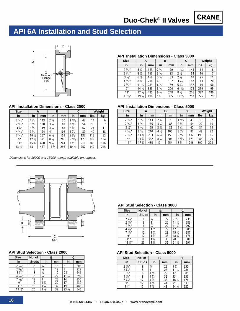
API 6A Installation and Stud Selection
Dimensions for 10000 and 15000 ratings available on request.
2 1⁄16" 8 5⁄8 16 8 2032 9⁄16" 8 3⁄4 19 9 2293 1⁄8" 8 3⁄4 19 9 1⁄2 2414 1⁄16" 8 7⁄8 22 11 1⁄2 2927 1⁄16" 12 1 25 14 356
9" 12 1 1⁄8 29 17 43211" 16 1 1⁄4 32 19 483
13 5⁄8" 20 1 1⁄4 32 23 3⁄4 546
Size No. of B Cin Studs in mm in mm
API Stud Selection - Class 2000
2 1⁄16" 8 7⁄8 22 9 1⁄4 2352 9⁄16" 8 1 25 11 1⁄4 2863 1⁄8" 8 7⁄8 22 11 1⁄2 2924 1⁄16" 8 1 1⁄8 29 12 3057 1⁄16" 12 1 1⁄8 29 15 1⁄4 387
9" 12 1 3⁄8 35 18 3⁄4 47611" 16 1 3⁄8 35 20 508
13 5⁄8" 20 1 3⁄8 35 21 1⁄2 591
Size No. of B Cin Studs in mm in mm
API Stud Selection - Class 3000
2 1⁄16" 8 7⁄8 22 9 1⁄4 2352 9⁄16" 8 1 25 11 1⁄4 2863 1⁄8" 8 1 1⁄8 29 12 3054 1⁄16" 8 1 1⁄4 32 13 3307 1⁄16" 12 1 3⁄8 35 18 3⁄4 476
9" 12 1 5⁄8 41 21 53311" 12 1 7⁄8 48 24 1⁄2 622
Size No. of B Cin Studs in mm in mm
API Stud Selection - Class 5000
B
CMin
2 1⁄16" 5 5⁄8 143 2 3⁄4 70 1 11⁄16 43 15 72 9⁄16" 6 1⁄2 165 3 1⁄4 83 2 1⁄8 54 22 103 1⁄8" 6 7⁄8 175 3 3⁄8 86 2 5⁄8 67 31 144 1⁄16" 8 1⁄4 210 4 1⁄8 105 3 7⁄16 87 49 227 1⁄16" 11 1⁄8 283 6 1⁄4 159 5 3⁄16 132 190 86
9" 13 7⁄8 352 8 1⁄8 206 6 13⁄16 173 285 12911" 17 1⁄8 435 10 254 8 1⁄2 216 502 228
Size A B C Weightin in mm in mm in mm lbs. kg.
API Installation Dimensions - Class 5000
2 1⁄16" 4 3⁄8 143 2 3⁄4 70 1 11⁄16 43 14 62 9⁄16" 5 1⁄8 130 3 1⁄4 83 2 1⁄8 54 16 73 1⁄8" 5 7⁄8 149 3 1⁄4 83 2 5⁄8 67 24 114 1⁄16" 7 5⁄8 194 4 102 3 7⁄16 87 40 187 1⁄16" 10 1⁄2 267 6 1⁄4 159 5 3⁄16 132 115 52
9" 12 5⁄8 321 8 1⁄8 206 6 13⁄16 173 229 10411" 15 3⁄4 400 9 1⁄2 241 8 1⁄2 216 388 176
13 5⁄8" 18 457 11 1⁄2 292 10 1⁄8 257 540 245
Size A B C Weightin in mm in mm in mm lbs. kg.
API Installation Dimensions - Class 2000
2 1⁄16" 5 5⁄8 143 2 3⁄4 70 1 11⁄16 43 14 62 9⁄16" 6 1⁄2 165 3 1⁄4 83 2 1⁄8 54 16 73 1⁄8" 6 5⁄8 168 3 1⁄4 83 2 5⁄8 67 25 114 1⁄16" 8 1⁄8 206 4 102 3 7⁄16 87 43 207 1⁄16" 11 3⁄8 289 6 1⁄4 159 5 3⁄16 132 110 50
9" 14 1⁄8 359 8 1⁄8 206 6 13⁄16 173 219 9911" 17 1⁄8 435 9 3⁄4 248 8 1⁄2 216 397 180
13 5⁄8" 19 5⁄8 498 12 305 10 1⁄8 257 725 329
Size A B C Weightin in mm in mm in mm lbs. kg.
API Installation Dimensions - Class 3000
B
A
CMinimumFlangeBore
17T: 936-588-4447 • F: 936-588-4427 • www.cranevalve.com
Duo-Chek® II Valves
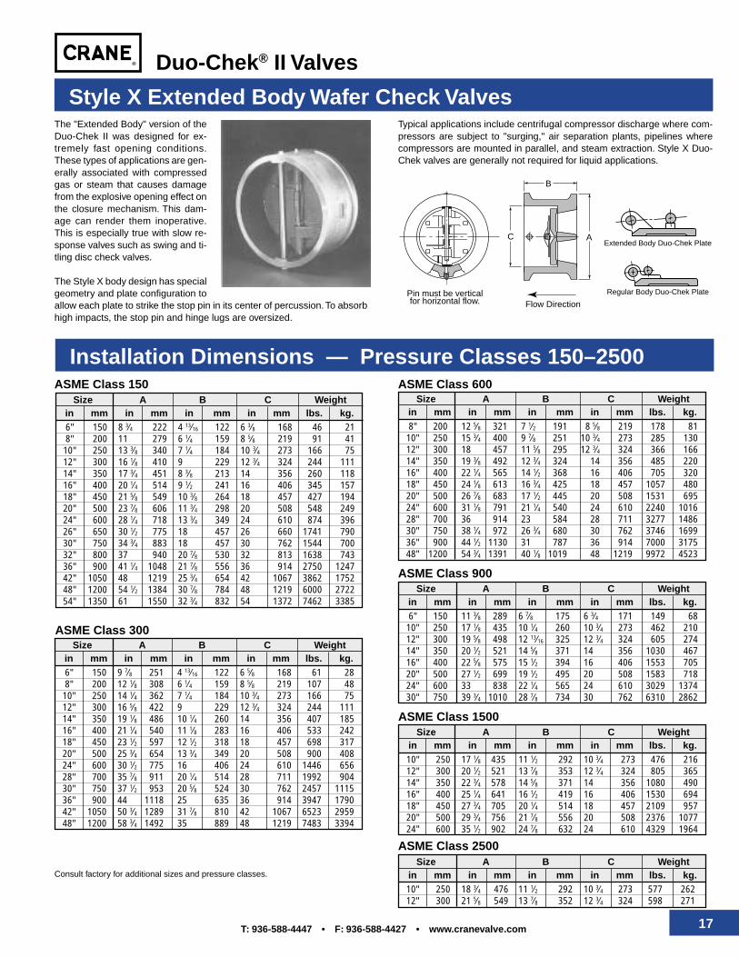
10" 250 17 1⁄8 435 11 1⁄2 292 10 3⁄4 273 476 21612" 300 20 1⁄2 521 13 7⁄8 353 12 3⁄4 324 805 36514" 350 22 3⁄4 578 14 5⁄8 371 14 356 1080 49016" 400 25 1⁄4 641 16 1⁄2 419 16 406 1530 69418" 450 27 3⁄4 705 20 1⁄4 514 18 457 2109 95720" 500 29 3⁄4 756 21 7⁄8 556 20 508 2376 107724" 600 35 1⁄2 902 24 7⁄8 632 24 610 4329 1964
6" 150 9 7⁄8 251 4 13⁄16 122 6 5⁄8 168 61 288" 200 12 1⁄8 308 6 1⁄4 159 8 5⁄8 219 107 48
10" 250 14 1⁄4 362 7 1⁄4 184 10 3⁄4 273 166 7512" 300 16 5⁄8 422 9 229 12 3⁄4 324 244 11114" 350 19 1⁄8 486 10 1⁄4 260 14 356 407 18516" 400 21 1⁄4 540 11 1⁄8 283 16 406 533 24218" 450 23 1⁄2 597 12 1⁄2 318 18 457 698 31720" 500 25 3⁄4 654 13 3⁄4 349 20 508 900 40824" 600 30 1⁄2 775 16 406 24 610 1446 65628" 700 35 7⁄8 911 20 1⁄4 514 28 711 1992 90430" 750 37 1⁄2 953 20 5⁄8 524 30 762 2457 111536" 900 44 1118 25 635 36 914 3947 179042" 1050 50 3⁄4 1289 31 7⁄8 810 42 1067 6523 295948" 1200 58 3⁄4 1492 35 889 48 1219 7483 3394
C
Pin must be verticalfor horizontal flow. Flow Direction
A
B
ASME Class 150Size A B C Weight
in mm in mm in mm in mm lbs. kg.6" 150 8 3⁄4 222 4 13⁄16 122 6 3⁄8 168 46 218" 200 11 279 6 1⁄4 159 8 5⁄8 219 91 41
10" 250 13 3⁄8 340 7 1⁄4 184 10 3⁄4 273 166 7512" 300 16 1⁄8 410 9 229 12 3⁄4 324 244 11114" 350 17 3⁄4 451 8 3⁄8 213 14 356 260 11816" 400 20 1⁄4 514 9 1⁄2 241 16 406 345 15718" 450 21 5⁄8 549 10 3⁄8 264 18 457 427 19420" 500 23 7⁄8 606 11 3⁄4 298 20 508 548 24924" 600 28 1⁄4 718 13 3⁄4 349 24 610 874 39626" 650 30 1⁄2 775 18 457 26 660 1741 79030" 750 34 3⁄4 883 18 457 30 762 1544 70032" 800 37 940 20 7⁄8 530 32 813 1638 74336" 900 41 1⁄4 1048 21 7⁄8 556 36 914 2750 124742" 1050 48 1219 25 3⁄4 654 42 1067 3862 175248" 1200 54 1⁄2 1384 30 7⁄8 784 48 1219 6000 272254" 1350 61 1550 32 3⁄4 832 54 1372 7462 3385
ASME Class 300Size A B C Weight
in mm in mm in mm in mm lbs. kg.
ASME Class 600Size A B C Weight
in mm in mm in mm in mm lbs. kg.8" 200 12 5⁄8 321 7 1⁄2 191 8 5⁄8 219 178 81
10" 250 15 3⁄4 400 9 7⁄8 251 10 3⁄4 273 285 13012" 300 18 457 11 5⁄8 295 12 3⁄4 324 366 16614" 350 19 3⁄8 492 12 3⁄4 324 14 356 485 22016" 400 22 1⁄4 565 14 1⁄2 368 16 406 705 32018" 450 24 1⁄8 613 16 3⁄4 425 18 457 1057 48020" 500 26 7⁄8 683 17 1⁄2 445 20 508 1531 69524" 600 31 1⁄8 791 21 1⁄4 540 24 610 2240 101628" 700 36 914 23 584 28 711 3277 148630" 750 38 1⁄4 972 26 3⁄4 680 30 762 3746 169936" 900 44 1⁄2 1130 31 787 36 914 7000 317548" 1200 54 3⁄4 1391 40 1⁄8 1019 48 1219 9972 4523
ASME Class 900Size A B C Weight
in mm in mm in mm in mm lbs. kg.6" 150 11 3⁄8 289 6 7⁄8 175 6 3⁄4 171 149 68
10" 250 17 1⁄8 435 10 1⁄4 260 10 3⁄4 273 462 21012" 300 19 5⁄8 498 12 13⁄16 325 12 3⁄4 324 605 27414" 350 20 1⁄2 521 14 5⁄8 371 14 356 1030 46716" 400 22 5⁄8 575 15 1⁄2 394 16 406 1553 70520" 500 27 1⁄2 699 19 1⁄2 495 20 508 1583 71824" 600 33 838 22 1⁄4 565 24 610 3029 137430" 750 39 3⁄4 1010 28 7⁄8 734 30 762 6310 2862
ASME Class 1500Size A B C Weight
in mm in mm in mm in mm lbs. kg.
ASME Class 2500Size A B C Weight
in mm in mm in mm in mm lbs. kg.10" 250 18 3⁄4 476 11 1⁄2 292 10 3⁄4 273 577 26212" 300 21 5⁄8 549 13 7⁄8 352 12 3⁄4 324 598 271
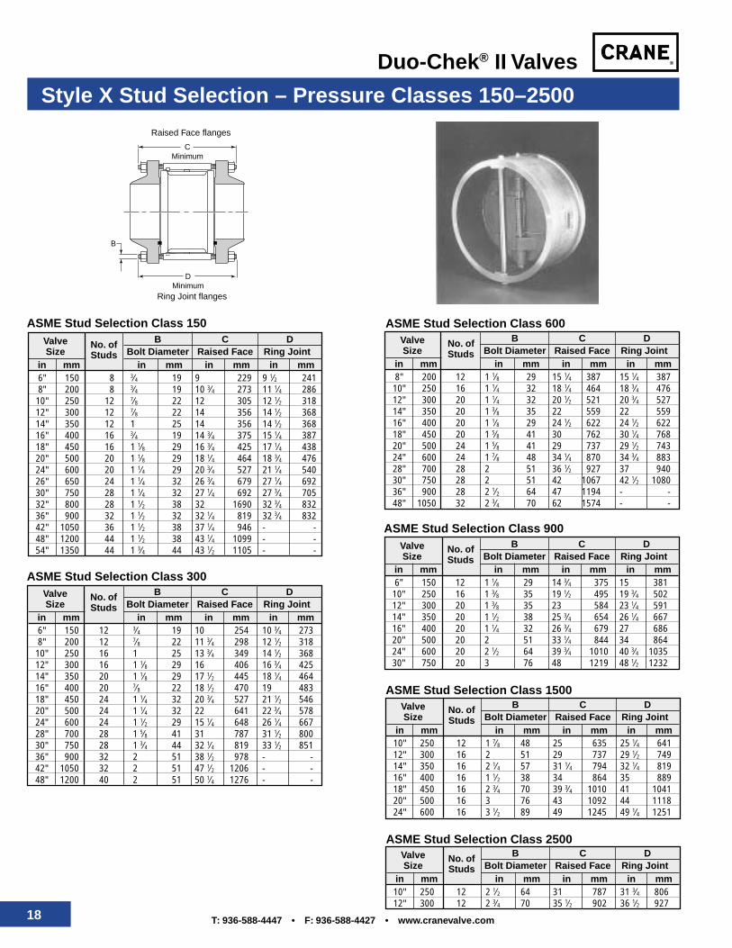
Style X Extended Body Wafer Check Valves
Consult factory for additional sizes and pressure classes.
The "Extended Body" version of theDuo-Chek II was designed for ex-tremely fast opening conditions.These types of applications are gen-erally associated with compressedgas or steam that causes damagefrom the explosive opening effect onthe closure mechanism. This dam-age can render them inoperative.This is especially true with slow re-sponse valves such as swing and ti-tling disc check valves.
The Style X body design has specialgeometry and plate configuration toallow each plate to strike the stop pin in its center of percussion. To absorbhigh impacts, the stop pin and hinge lugs are oversized.
Extended Body Duo-Chek Plate
Regular Body Duo-Chek Plate
Typical applications include centrifugal compressor discharge where com-pressors are subject to "surging," air separation plants, pipelines wherecompressors are mounted in parallel, and steam extraction. Style X Duo-Chek valves are generally not required for liquid applications.
Installation Dimensions — Pressure Classes 150–2500
18 T: 936-588-4447 • F: 936-588-4427 • www.cranevalve.com
Duo-Chek® II Valves
8" 200 12 1 1⁄8 29 15 1⁄4 387 15 1⁄4 38710" 250 16 1 1⁄4 32 18 1⁄4 464 18 3⁄4 47612" 300 20 1 1⁄4 32 20 1⁄2 521 20 3⁄4 52714" 350 20 1 3⁄8 35 22 559 22 55916" 400 20 1 1⁄8 29 24 1⁄2 622 24 1⁄2 62218" 450 20 1 5⁄8 41 30 762 30 1⁄4 76820" 500 24 1 5⁄8 41 29 737 29 1⁄2 74324" 600 24 1 7⁄8 48 34 1⁄4 870 34 3⁄4 88328" 700 28 2 51 36 1⁄2 927 37 94030" 750 28 2 51 42 1067 42 1⁄2 108036" 900 28 2 1⁄2 64 47 1194 - -48" 1050 32 2 3⁄4 70 62 1574 - -
Valve No. of B C DSize Studs Bolt Diameter Raised Face Ring Joint
in mm in mm in mm in mm
ASME Stud Selection Class 600
10" 250 12 2 1⁄2 64 31 787 31 3⁄4 80612" 300 12 2 3⁄4 70 35 1⁄2 902 36 1⁄2 927
Raised Face flanges
CMinimum
Ring Joint flanges
DMinimum
B
Style X Stud Selection – Pressure Classes 150–2500
6" 150 8 3⁄4 19 9 229 9 1⁄2 2418" 200 8 3⁄4 19 10 3⁄4 273 11 1⁄4 286
10" 250 12 7⁄8 22 12 305 12 1⁄2 31812" 300 12 7⁄8 22 14 356 14 1⁄2 36814" 350 12 1 25 14 356 14 1⁄2 36816" 400 16 3⁄4 19 14 3⁄4 375 15 1⁄4 38718" 450 16 1 1⁄8 29 16 3⁄4 425 17 1⁄4 43820" 500 20 1 1⁄8 29 18 1⁄4 464 18 3⁄4 47624" 600 20 1 1⁄4 29 20 3⁄4 527 21 1⁄4 54026" 650 24 1 1⁄4 32 26 3⁄4 679 27 1⁄4 69230" 750 28 1 1⁄4 32 27 1⁄4 692 27 3⁄4 70532" 800 28 1 1⁄2 38 32 1690 32 3⁄4 83236" 900 32 1 1⁄2 32 32 1⁄4 819 32 3⁄4 83242" 1050 36 1 1⁄2 38 37 1⁄4 946 - -48" 1200 44 1 1⁄2 38 43 1⁄4 1099 - -54" 1350 44 1 3⁄4 44 43 1⁄2 1105 - -
Valve No. of B C DSize Studs Bolt Diameter Raised Face Ring Joint
in mm in mm in mm in mm
ASME Stud Selection Class 150
6" 150 12 3⁄4 19 10 254 10 3⁄4 2738" 200 12 7⁄8 22 11 3⁄4 298 12 1⁄2 318
10" 250 16 1 25 13 3⁄4 349 14 1⁄2 36812" 300 16 1 1⁄8 29 16 406 16 3⁄4 42514" 350 20 1 1⁄8 29 17 1⁄2 445 18 1⁄4 46416" 400 20 7⁄8 22 18 1⁄2 470 19 48318" 450 24 1 1⁄4 32 20 3⁄4 527 21 1⁄2 54620" 500 24 1 1⁄4 32 22 641 22 3⁄4 57824" 600 24 1 1⁄2 29 15 1⁄4 648 26 1⁄4 66728" 700 28 1 5⁄8 41 31 787 31 1⁄2 80030" 750 28 1 3⁄4 44 32 1⁄4 819 33 1⁄2 85136" 900 32 2 51 38 1⁄2 978 - -42" 1050 32 2 51 47 1⁄2 1206 - -48" 1200 40 2 51 50 1⁄4 1276 - -
Valve No. of B C DSize Studs Bolt Diameter Raised Face Ring Joint
in mm in mm in mm in mm
ASME Stud Selection Class 300 6" 150 12 1 1⁄8 29 14 3⁄4 375 15 38110" 250 16 1 3⁄8 35 19 1⁄2 495 19 3⁄4 50212" 300 20 1 3⁄8 35 23 584 23 1⁄4 59114" 350 20 1 1⁄2 38 25 3⁄4 654 26 1⁄4 66716" 400 20 1 1⁄4 32 26 3⁄4 679 27 68620" 500 20 2 51 33 1⁄4 844 34 86424" 600 20 2 1⁄2 64 39 3⁄4 1010 40 3⁄4 103530" 750 20 3 76 48 1219 48 1⁄2 1232
Valve No. of B C DSize Studs Bolt Diameter Raised Face Ring Joint
in mm in mm in mm in mm
ASME Stud Selection Class 900
10" 250 12 1 7⁄8 48 25 635 25 1⁄4 64112" 300 16 2 51 29 737 29 1⁄2 74914" 350 16 2 1⁄4 57 31 1⁄4 794 32 1⁄4 81916" 400 16 1 1⁄2 38 34 864 35 88918" 450 16 2 3⁄4 70 39 3⁄4 1010 41 104120" 500 16 3 76 43 1092 44 111824" 600 16 3 1⁄2 89 49 1245 49 1⁄4 1251
Valve No. of B C DSize Studs Bolt Diameter Raised Face Ring Joint
in mm in mm in mm in mm
ASME Stud Selection Class 1500
Valve No. of B C DSize Studs Bolt Diameter Raised Face Ring Joint
in mm in mm in mm in mm
ASME Stud Selection Class 2500
19T: 936-588-4447 • F: 936-588-4427 • www.cranevalve.com
Duo-Chek® II Valves
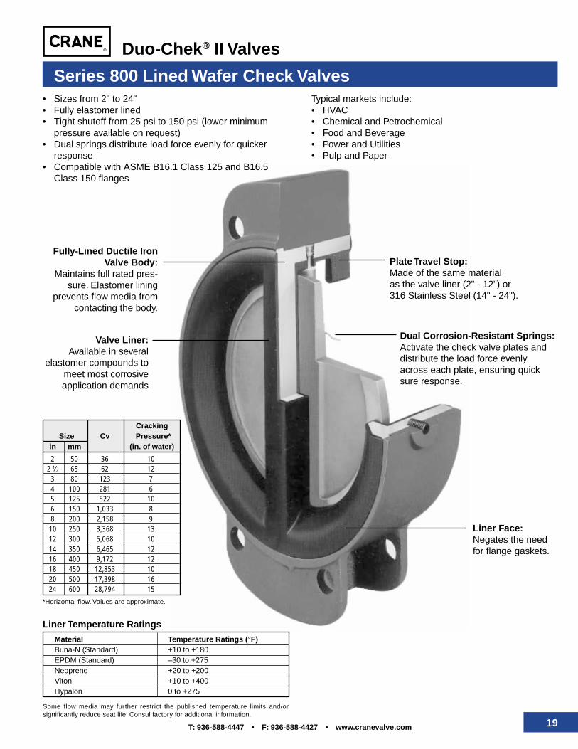
Series 800 Lined Wafer Check Valves
Fully-Lined Ductile IronValve Body:
Maintains full rated pres-sure. Elastomer lining
prevents flow media fromcontacting the body.
Valve Liner:Available in several
elastomer compounds tomeet most corrosiveapplication demands
Dual Corrosion-Resistant Springs:Activate the check valve plates anddistribute the load force evenlyacross each plate, ensuring quicksure response.
Plate Travel Stop:Made of the same materialas the valve liner (2" - 12") or316 Stainless Steel (14" - 24").
Liner Face:Negates the needfor flange gaskets.
Material Temperature Ratings (°F)Buna-N (Standard) +10 to +180EPDM (Standard) –30 to +275Neoprene +20 to +200Viton +10 to +400Hypalon 0 to +275
Liner Temperature Ratings
Some flow media may further restrict the published temperature limits and/orsignificantly reduce seat life. Consul factory for additional information.
• Sizes from 2" to 24"• Fully elastomer lined• Tight shutoff from 25 psi to 150 psi (lower minimum
pressure available on request)• Dual springs distribute load force evenly for quicker
response• Compatible with ASME B16.1 Class 125 and B16.5
Class 150 flanges
Typical markets include:• HVAC• Chemical and Petrochemical• Food and Beverage• Power and Utilities• Pulp and Paper
CrackingSize Cv *Pressure*
in mm (in. of water)
2 50 36 102 1⁄2 65 62 123 80 123 74 100 281 65 125 522 106 150 1,033 88 200 2,158 910 250 3,368 1312 300 5,068 1014 350 6,465 1216 400 9,172 1218 450 12,853 1020 500 17,398 1624 600 28,794 15
*Horizontal flow. Values are approximate.
20 T: 936-588-4447 • F: 936-588-4427 • www.cranevalve.com
Duo-Chek® II Valves
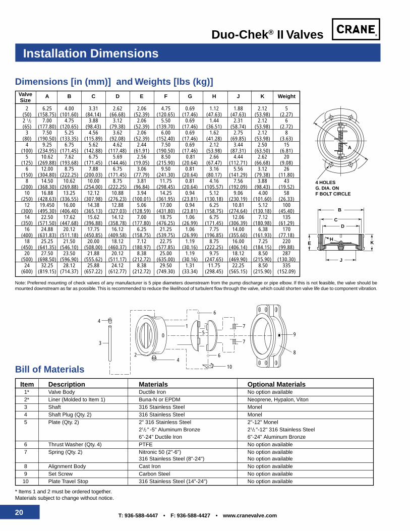
Installation Dimensions
A B C D E F G H J K Weight
2 6.25 4.00 3.31 2.62 2.06 4.75 0.69 1.12 1.88 2.12 5(50) (158.75) (101.60) (84.14) (66.68) (52.39) (120.65) (17.46) (47.63) (47.63) (53.98) (2.27)2 1/2 7.00 4.75 3.88 3.12 2.06 5.50 0.69 1.44 2.31 2.12 6(65) (177.80) (120.65) (98.43) (79.38) (52.39) (139.70) (17.46) (36.51) (58.74) (53.98) (2.72)
3 7.50 5.25 4.56 3.62 2.06 6.00 0.69 1.62 2.75 2.12 8(80) (190.50) (133.35) (115.89) (92.08) (52.39) (152.40) (17.46) (41.28) (69.85) (53.98) (3.63)
4 9.25 6.75 5.62 4.62 2.44 7.50 0.69 2.12 3.44 2.50 15(100) (234.95) (171.45) (142.88) (117.48) (61.91) (190.50) (17.46) (53.98) (87.31) (63.50) (6.81)
5 10.62 7.62 6.75 5.69 2.56 8.50 0.81 2.66 4.44 2.62 20(125) (269.88) (193.68) (171.45) (144.46) (19.05) (215.90) (20.64) (67.47) (112.71) (66.68) (9.08)
6 12.00 8.75 7.88 6.75 3.06 9.50 0.81 3.16 5.56 3.12 26(150) (304.80) (222.25) (200.03) (171.45) (77.79) (241.30) (20.64) (80.17) (141.29) (79.38) (11.80)
8 14.50 10.62 10.00 8.75 3.81 11.75 0.81 4.16 7.56 3.88 43(200) (368.30) (269.88) (254.00) (222.25) (96.84) (298.45) (20.64) (105.57) (192.09) (98.43) (19.52)
10 16.88 13.25 12.12 10.88 3.94 14.25 0.94 5.12 9.06 4.00 58(250) (428.63) (336.55) (307.98) (276.23) (100.01) (361.95) (23.81) (130.18) (230.19) (101.60) (26.33)
12 19.450 16.00 14.38 12.88 5.06 17.00 0.94 6.25 10.81 5.12 100(300) (495.30) (406.40) (365.13) (327.03) (128.59) (431.80) (23.81) (158.75) (274.64) (130.18) (45.40)
14 22.50 17.62 15.62 14.12 7.00 18.75 1.06 6.75 12.06 7.12 135(350) (571.50) (447.68) (396.88) (358.78) (177.80) (476.25) (26.99) (171.45) (306.39) (180.98) (61.29)
16 24.88 20.12 17.75 16.12 6.25 21.25 1.06 7.75 14.00 6.38 170(400) (631.83) (511.18) (450.85) (409.58) (158.75) (539.75) (26.99) (196.85) (355.60) (161.93) (77.18)
18 25.25 21.50 20.00 18.12 7.12 22.75 1.19 8.75 16.00 7.25 220(450) (641.35) (546.10) (508.00) (460.37) (180.97) (577.85) (30.16) (222.25) (406.14) (184.15) (99.88)
20 27.50 23.50 21.88 20.12 8.38 25.00 1.19 9.75 18.12 8.50 287(500) (698.50) (596.90) (555.62) (511.17) (212.72) (635.00) (30.16) (247.65) (469.90) (215.90) (130.30)
24 32.25 28.12 25.88 24.12 8.38 29.50 1.31 11.75 22.25 8.50 335(600) (819.15) (714.37) (657.22) (612.77) (212.72) (749.30) (33.34) (298.45) (565.15) (215.90) (152.09)
* Items 1 and 2 must be ordered together.Materials subject to change without notice.
Item Description Materials Optional Materials*1* Valve Body Ductile Iron No option available*2* Liner (Molded to Item 1) Buna-N or EPDM Neoprene, Hypalon, Viton3 Shaft 316 Stainless Steel Monel4 Shaft Plug (Qty. 2) 316 Stainless Steel Monel5 Plate (Qty. 2) 2" 316 Stainless Steel 2"-12" Monel
21/2 " -5" Aluminum Bronze 21/2 "-12" 316 Stainless Steel6"-24" Ductile Iron 6"-24" Aluminum Bronze
6 Thrust Washer (Qty. 4) PTFE No option available7 Spring (Qty. 2) Nitronic 50 (2"-6") No option available
316 Stainless Steel (8"-24") No option available8 Alignment Body Cast Iron No option available9 Set Screw Carbon Steel No option available
10 Plate Travel Stop 316 Stainless Steel (14"-24") No option available
Note: Preferred mounting of check valves of any manufacturer is 5 pipe diameters downstream from the pump discharge or pipe elbow. If this is not feasible, the valve should bemounted downstream as far as possible. This is recommended to reduce the likelihood of turbulent flow through the valve, which could shorten valve life due to component vibration.
ValveSize
Bill of Materials
Dimensions [in (mm)] and Weights [lbs (kg)]
14
4
6
5
6
9
8
10
7
73
2
H
D
J
C
B
KE
4 HOLESG. DIA. ONF BOLT CIRCLE
A
21T: 936-588-4447 • F: 936-588-4427 • www.cranevalve.com
Duo-Chek® II Valves
0.1
10 20 30 40 50 60 70 100
200
300
400
500
600
700
1000
2000
3000
4000
5000
6000
7000
1000
0
2000
0
3000
0
4000
0
5000
0
6000
0
7000
0
1000
00
2000
00
3000
00
4000
00
5000
00
6000
0070
0000
1000
000
0.2
0.3
0.50.60.7
1.0
0.6
1.3
1.9
2.5
3.2
3.8
4.4 6 13 19 25 32 38 44 63 126
189
252
315
378
442
631
1262
1892
2523
3154
3785
4416
6308
1261
6
1892
4
2523
2
3154
0
3784
844
156
6308
0
0.4
2.0
3.0
4.0
5.06.07.0
10
20
30
40
506070
100
0.03
0.06
0.09
HEAD
LOS
S IN
MET
ERS
OF W
ATER
GALLONS PER MINUTE
LITERS PER MINUTE
HEAD
LOS
S IN
FEE
T OF
WAT
ER
0.12
0.150.180.21
0.3
0.6
0.9
1.2
1.51.82.1
3.0
6.1
9.1
12.2
15.218.321.3
30.5
2" V
ALVE 3"
2 1/
2""
5" 6" 8" 10"
12"
14"
16"
18"
20"
24"
30"
36"
42"
48"
54"
60"
66"
72"
LOSSES SHOWN BASES ON WATER AT 60°F WITH SP. GR. OF 1.0
4"
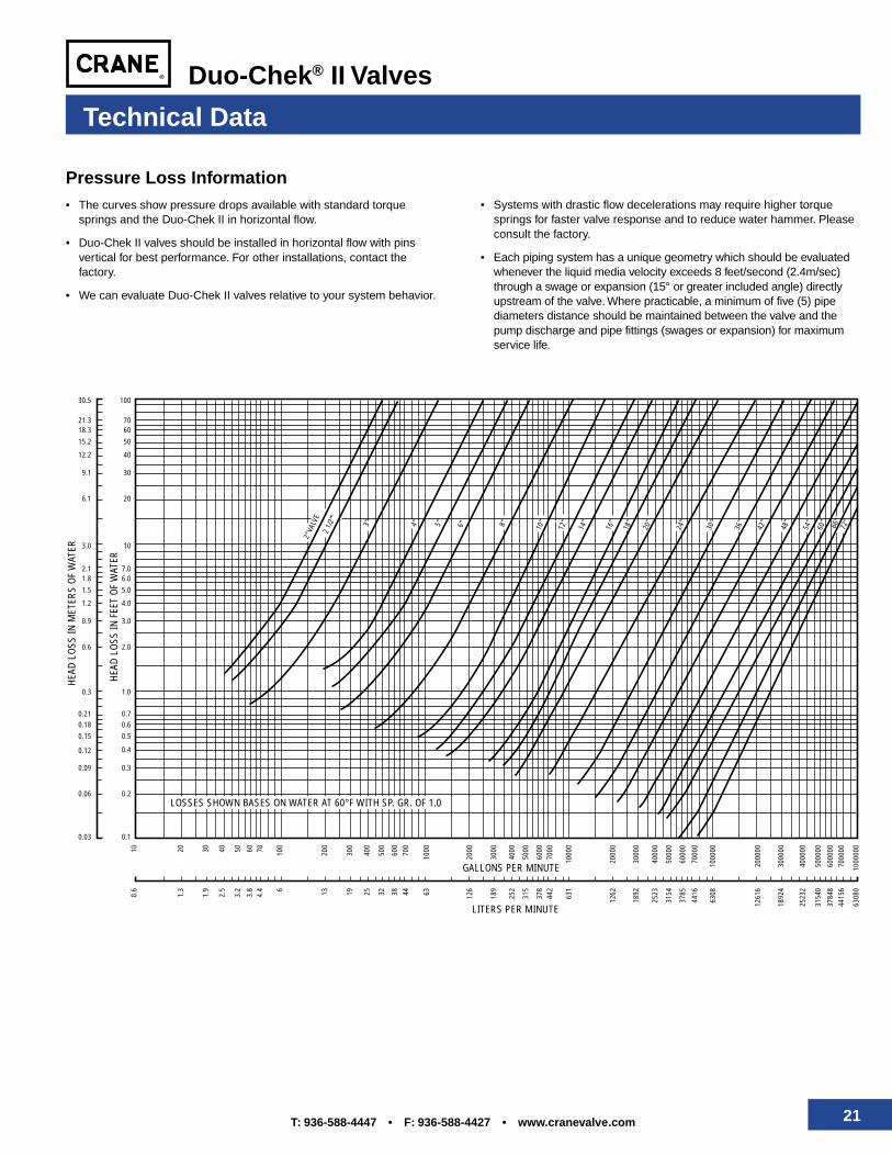
Technical Data
Pressure Loss Information• The curves show pressure drops available with standard torque
springs and the Duo-Chek II in horizontal flow.
• Duo-Chek II valves should be installed in horizontal flow with pinsvertical for best performance. For other installations, contact thefactory.
• We can evaluate Duo-Chek II valves relative to your system behavior.
• Systems with drastic flow decelerations may require higher torquesprings for faster valve response and to reduce water hammer. Pleaseconsult the factory.
• Each piping system has a unique geometry which should be evaluatedwhenever the liquid media velocity exceeds 8 feet/second (2.4m/sec)through a swage or expansion (15° or greater included angle) directlyupstream of the valve. Where practicable, a minimum of five (5) pipediameters distance should be maintained between the valve and thepump discharge and pipe fittings (swages or expansion) for maximumservice life.
22 T: 936-588-4447 • F: 936-588-4427 • www.cranevalve.com
Duo-Chek® II Valves
Spring & Drain Size Information
Technical Data
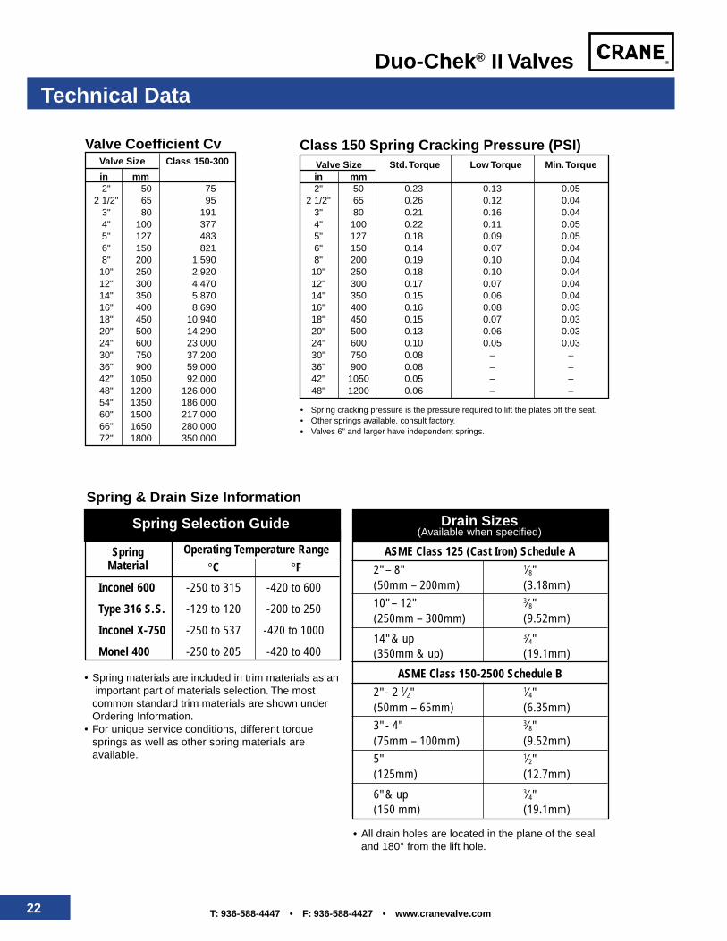
ASME Class 125 (Cast Iron) Schedule A2" – 8" 1⁄8"(50mm – 200mm) (3.18mm)10" – 12" 3⁄8"(250mm – 300mm) (9.52mm)
14" & up 3⁄4"(350mm & up) (19.1mm)
ASME Class 150-2500 Schedule B2" - 2 1⁄2" 1⁄4"(50mm – 65mm) (6.35mm)3" - 4" 3⁄8"(75mm – 100mm) (9.52mm)5" 1⁄2"(125mm) (12.7mm)
6" & up 3⁄4"(150 mm) (19.1mm)
Drain Sizes(Available when specified)
Spring Operating Temperature RangeMaterial °C °F
Inconel 600 -250 to 315 -420 to 600
Type 316 S.S. -129 to 120 -200 to 250
Inconel X-750 -250 to 537 -420 to 1000
Monel 400 -250 to 205 -420 to 400
Spring Selection Guide
• Spring materials are included in trim materials as an important part of materials selection. The mostcommon standard trim materials are shown underOrdering Information.
• For unique service conditions, different torquesprings as well as other spring materials areavailable.
• All drain holes are located in the plane of the sealand 180° from the lift hole.
Valve Coefficient CvValve Size Class 150-300
in mm2" 50 75
2 1/2" 65 953" 80 1914" 100 3775" 127 4836" 150 8218" 200 1,59010" 250 2,92012" 300 4,47014" 350 5,87016" 400 8,69018" 450 10,94020" 500 14,29024" 600 23,00030" 750 37,20036" 900 59,00042" 1050 92,00048" 1200 126,00054" 1350 186,00060" 1500 217,00066" 1650 280,00072" 1800 350,000
Class 150 Spring Cracking Pressure (PSI)Valve Size Std. Torque Low Torque Min. Torquein mm2" 50 0.23 0.13 0.05
2 1/2" 65 0.26 0.12 0.043" 80 0.21 0.16 0.044" 100 0.22 0.11 0.055" 127 0.18 0.09 0.056" 150 0.14 0.07 0.048" 200 0.19 0.10 0.04
10" 250 0.18 0.10 0.0412" 300 0.17 0.07 0.0414" 350 0.15 0.06 0.0416" 400 0.16 0.08 0.0318" 450 0.15 0.07 0.0320" 500 0.13 0.06 0.0324" 600 0.10 0.05 0.0330" 750 0.08 – –36" 900 0.08 – –42" 1050 0.05 – –48" 1200 0.06 – –
• Spring cracking pressure is the pressure required to lift the plates off the seat.• Other springs available, consult factory.• Valves 6" and larger have independent springs.
23T: 936-588-4447 • F: 936-588-4427 • www.cranevalve.com
Duo-Chek® II Valves
Technical Data
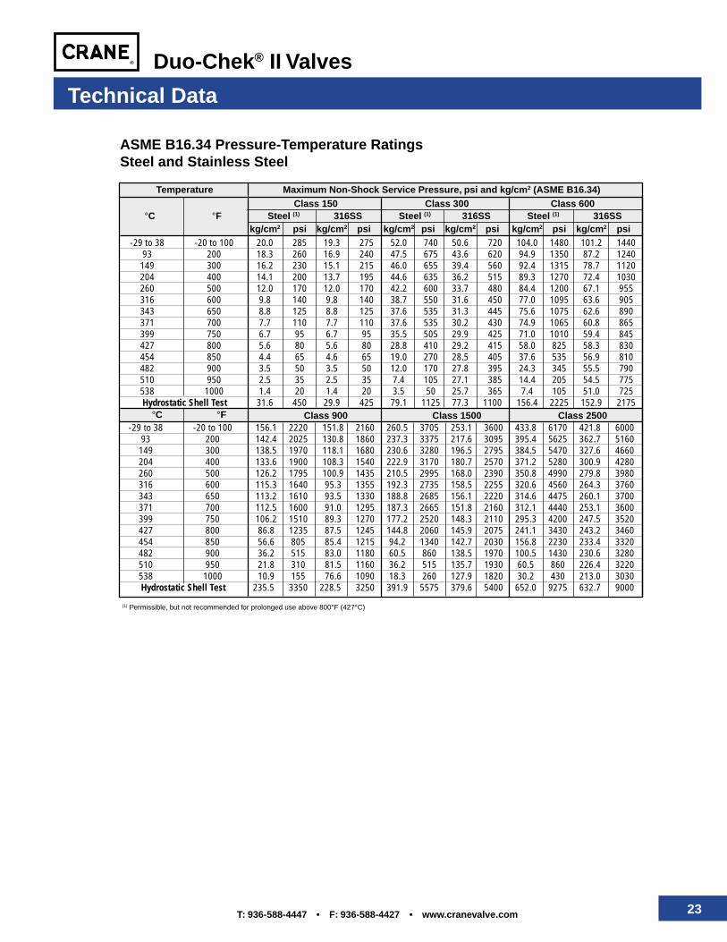
°C °F Class 900 Class 1500 Class 2500-29 to 38 -20 to 100 156.1 2220 151.8 2160 260.5 3705 253.1 3600 433.8 6170 421.8 6000
93 200 142.4 2025 130.8 1860 237.3 3375 217.6 3095 395.4 5625 362.7 5160149 300 138.5 1970 118.1 1680 230.6 3280 196.5 2795 384.5 5470 327.6 4660204 400 133.6 1900 108.3 1540 222.9 3170 180.7 2570 371.2 5280 300.9 4280260 500 126.2 1795 100.9 1435 210.5 2995 168.0 2390 350.8 4990 279.8 3980316 600 115.3 1640 95.3 1355 192.3 2735 158.5 2255 320.6 4560 264.3 3760343 650 113.2 1610 93.5 1330 188.8 2685 156.1 2220 314.6 4475 260.1 3700371 700 112.5 1600 91.0 1295 187.3 2665 151.8 2160 312.1 4440 253.1 3600399 750 106.2 1510 89.3 1270 177.2 2520 148.3 2110 295.3 4200 247.5 3520427 800 86.8 1235 87.5 1245 144.8 2060 145.9 2075 241.1 3430 243.2 3460454 850 56.6 805 85.4 1215 94.2 1340 142.7 2030 156.8 2230 233.4 3320482 900 36.2 515 83.0 1180 60.5 860 138.5 1970 100.5 1430 230.6 3280510 950 21.8 310 81.5 1160 36.2 515 135.7 1930 60.5 860 226.4 3220538 1000 10.9 155 76.6 1090 18.3 260 127.9 1820 30.2 430 213.0 3030Hydrostatic Shell Test 235.5 3350 228.5 3250 391.9 5575 379.6 5400 652.0 9275 632.7 9000
-29 to 38 -20 to 100 20.0 285 19.3 275 52.0 740 50.6 720 104.0 1480 101.2 144093 200 18.3 260 16.9 240 47.5 675 43.6 620 94.9 1350 87.2 1240149 300 16.2 230 15.1 215 46.0 655 39.4 560 92.4 1315 78.7 1120204 400 14.1 200 13.7 195 44.6 635 36.2 515 89.3 1270 72.4 1030260 500 12.0 170 12.0 170 42.2 600 33.7 480 84.4 1200 67.1 955316 600 9.8 140 9.8 140 38.7 550 31.6 450 77.0 1095 63.6 905343 650 8.8 125 8.8 125 37.6 535 31.3 445 75.6 1075 62.6 890371 700 7.7 110 7.7 110 37.6 535 30.2 430 74.9 1065 60.8 865399 750 6.7 95 6.7 95 35.5 505 29.9 425 71.0 1010 59.4 845427 800 5.6 80 5.6 80 28.8 410 29.2 415 58.0 825 58.3 830454 850 4.4 65 4.6 65 19.0 270 28.5 405 37.6 535 56.9 810482 900 3.5 50 3.5 50 12.0 170 27.8 395 24.3 345 55.5 790510 950 2.5 35 2.5 35 7.4 105 27.1 385 14.4 205 54.5 775538 1000 1.4 20 1.4 20 3.5 50 25.7 365 7.4 105 51.0 725Hydrostatic Shell Test 31.6 450 29.9 425 79.1 1125 77.3 1100 156.4 2225 152.9 2175
ASME B16.34 Pressure-Temperature RatingsSteel and Stainless Steel
Temperature Maximum Non-Shock Service Pressure, psi and kg/cm2 (ASME B16.34)Class 150 Class 300 Class 600
°C °F Steel (1) 316SS Steel (1) 316SS Steel (1) 316SSkg/cm2 psi kg/cm2 psi kg/cm2 psi kg/cm2 psi kg/cm2 psi kg/cm2 psi
(1) Permissible, but not recommended for prolonged use above 800°F (427°C)
24 T: 936-588-4447 • F: 936-588-4427 • www.cranevalve.com
Duo-Chek® II Valves
Ordering Information
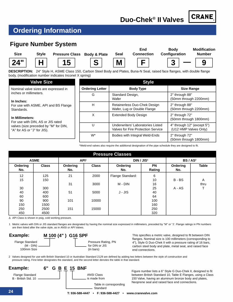
Figure Number System
Size Style Pressure Class Body & Plate SealBody
ConfigurationModification
Number
24" H 15 S M
EndConnection
F 3 9—DESCRIPTION: 24" Style H, ASME Class 150, Carbon Steel Body and Plates, Buna-N Seal, raised face flanges, with double flangebody, (modification number indicates Inconel X spring)
Nominal valve sizes are expressed ininches or millimeters.
In Inches:For use with ASME, API and BS FlangeStandards.
In Millimeters:For use with DIN, AS or JIS ratedvalves (size preceded by "M" for DIN,"A" for AS or "J" for JIS).
Valve SizeOrdering Letter Body Type Size Range
G Standard Design, 2" through 88"Wafer (50mm through 2200mm)
H Retainerless Duo-Chek Design 2" through 88"Wafer, Lug or Double Flange (50mm through 2200mm)
X Extended Body Design 2" through 72"(50mm through 1800mm)
U Underwriters’ Laboratories Listed 4" through 12" (except 5")Valves for Fire Protection Service (U12 HMP Valves Only)
W* Bodies with Integral Weld-Ends 2" through 72"(50mm through 1800mm)
Style
*Weld-end valves also require the additional designation of the pipe schedule they are designed to fit.
Pressure ClassesASME API∆ DIN / JIS1 BS / AS2
Ordering Class Ordering Class Ordering PN Ordering TableNo. No. No. Rating No.
12 125 21 2000 Flange Standard: 615 150 10 B - BS A
31 3000 M - DIN 16 thru30 300 25 A - AS T40 400 51 5000 J - JIS 4060 600 6490 900 101 10000 100150 1500 160250 2500 151 15000 250450 4500 320
∆ API Class is shown in psig, cold working pressure.
1 Metric valves with DIN or JIS standard flanges are designated by having the nominal size expressed in millimeters, preceded by "M" or "J'. Flange ratings in PN numbersare then listed after the valve style, as in ANSI or API Valves.
Example: M 100 (4" ) G16 SPFFlange Standard
(M - DIN)100mm Size
Pressure Rating, PNfor DIN or JIS(in bars)
This specifies a metric valve, designed to fit between DINflanges. Nominal size is 100 millimeters (corresponding to4"), Style G Duo-Chek II with a pressure rating of 16 bars,carbon steel body and plate, metal seat, and raised faceend connections.
2 Valves designed for use with British Standard 10 or Australian Standard 2129 are defined by adding two letters between the style of construction andpressure rating. First letter designates the standard, and the second letter denotes the table in that standard.
Figure number lists a 6" Style G Duo-Chek II, designed to fitbetween British Standard 10, Table E Flanges, using a Class150 Valve, having an aluminum bronze body and plates,Neoprene seal and raised face end connections.
Example: 6" G B E 15 BNFFlange Standard
B - British Std. 10ANSI Classis made from
Table in correspondingStandard
25T: 936-588-4447 • F: 936-588-4427 • www.cranevalve.com
Duo-Chek® II Valves
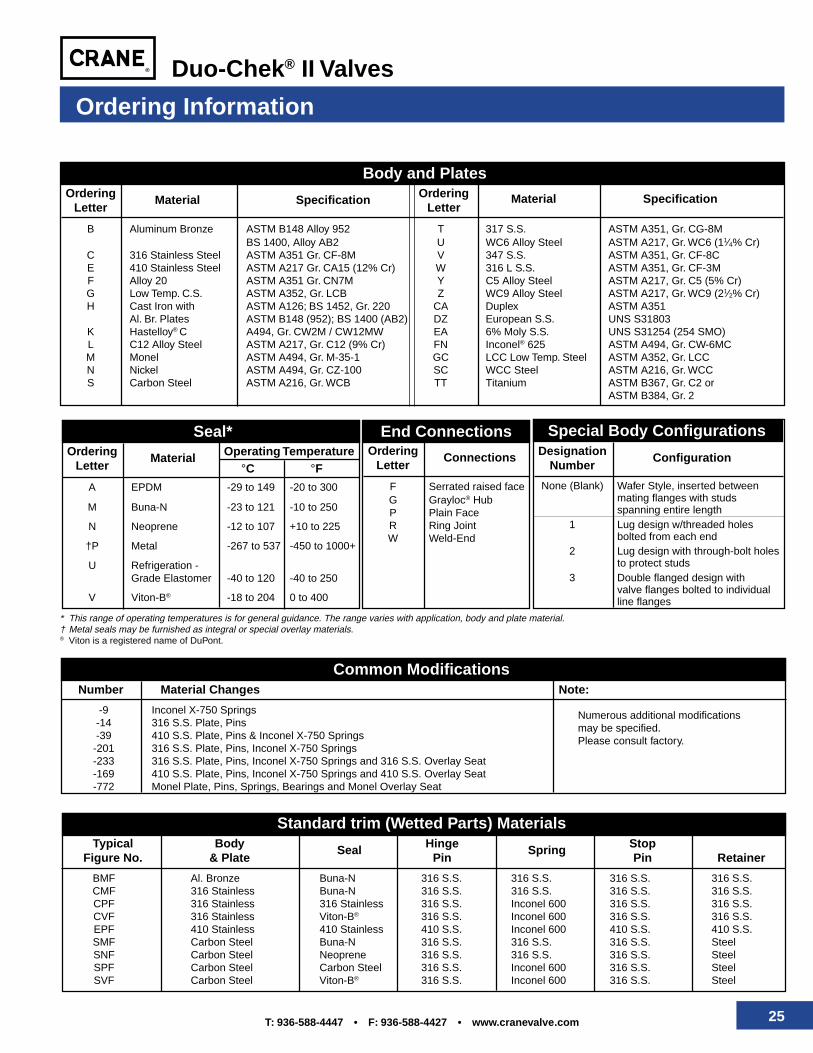
Number Material Changes Note:
-9 Inconel X-750 Springs-14 316 S.S. Plate, Pins-39 410 S.S. Plate, Pins & Inconel X-750 Springs
-201 316 S.S. Plate, Pins, Inconel X-750 Springs-233 316 S.S. Plate, Pins, Inconel X-750 Springs and 316 S.S. Overlay Seat-169 410 S.S. Plate, Pins, Inconel X-750 Springs and 410 S.S. Overlay Seat-772 Monel Plate, Pins, Springs, Bearings and Monel Overlay Seat
Ordering Information
Body and PlatesOrdering Material Specification Ordering Material Specification
Letter Letter
B Aluminum Bronze ASTM B148 Alloy 952 T 317 S.S. ASTM A351, Gr. CG-8MBS 1400, Alloy AB2 U WC6 Alloy Steel ASTM A217, Gr. WC6 (11⁄4% Cr)
C 316 Stainless Steel ASTM A351 Gr. CF-8M V 347 S.S. ASTM A351, Gr. CF-8CE 410 Stainless Steel ASTM A217 Gr. CA15 (12% Cr) W 316 L S.S. ASTM A351, Gr. CF-3MF Alloy 20 ASTM A351 Gr. CN7M Y C5 Alloy Steel ASTM A217, Gr. C5 (5% Cr)G Low Temp. C.S. ASTM A352, Gr. LCB Z WC9 Alloy Steel ASTM A217, Gr. WC9 (21⁄2% Cr)H Cast Iron with ASTM A126; BS 1452, Gr. 220 CA Duplex ASTM A351
Al. Br. Plates ASTM B148 (952); BS 1400 (AB2) DZ European S.S. UNS S31803K Hastelloy® C A494, Gr. CW2M / CW12MW EA 6% Moly S.S. UNS S31254 (254 SMO)L C12 Alloy Steel ASTM A217, Gr. C12 (9% Cr) FN Inconel® 625 ASTM A494, Gr. CW-6MCM Monel ASTM A494, Gr. M-35-1 GC LCC Low Temp. Steel ASTM A352, Gr. LCCN Nickel ASTM A494, Gr. CZ-100 SC WCC Steel ASTM A216, Gr. WCCS Carbon Steel ASTM A216, Gr. WCB TT Titanium ASTM B367, Gr. C2 or
ASTM B384, Gr. 2
Seal*Ordering Material Operating Temperature
Letter °C °FA EPDM -29 to 149 -20 to 300
M Buna-N -23 to 121 -10 to 250
N Neoprene -12 to 107 +10 to 225
†P Metal -267 to 537 -450 to 1000+
U Refrigeration -Grade Elastomer -40 to 120 -40 to 250
V Viton-B® -18 to 204 0 to 400
* This range of operating temperatures is for general guidance. The range varies with application, body and plate material.† Metal seals may be furnished as integral or special overlay materials.® Viton is a registered name of DuPont.
End ConnectionsOrdering Connections
Letter
F Serrated raised faceG Grayloc® HubP Plain FaceR Ring JointW Weld-End
Designation ConfigurationNumber
None (Blank) Wafer Style, inserted betweenmating flanges with studsspanning entire length
1 Lug design w/threaded holesbolted from each end
2 Lug design with through-bolt holesto protect studs
3 Double flanged design withvalve flanges bolted to individualline flanges
Special Body Configurations
Common Modifications
Numerous additional modificationsmay be specified.Please consult factory.
Standard trim (Wetted Parts) MaterialsTypical Body Seal Hinge Spring Stop
Figure No. & Plate Pin Pin Retainer
BMF Al. Bronze Buna-N 316 S.S. 316 S.S. 316 S.S. 316 S.S.CMF 316 Stainless Buna-N 316 S.S. 316 S.S. 316 S.S. 316 S.S.CPF 316 Stainless 316 Stainless 316 S.S. Inconel 600 316 S.S. 316 S.S.CVF 316 Stainless Viton-B® 316 S.S. Inconel 600 316 S.S. 316 S.S.EPF 410 Stainless 410 Stainless 410 S.S. Inconel 600 410 S.S. 410 S.S.SMF Carbon Steel Buna-N 316 S.S. 316 S.S. 316 S.S. SteelSNF Carbon Steel Neoprene 316 S.S. 316 S.S. 316 S.S. SteelSPF Carbon Steel Carbon Steel 316 S.S. Inconel 600 316 S.S. SteelSVF Carbon Steel Viton-B® 316 S.S. Inconel 600 316 S.S. Steel
26 T: 936-588-4447 • F: 936-588-4427 • www.cranevalve.com
Duo-Chek® II Valves
Duo-Chek II Specials
Coated Valves
A variety of coatings may be provided onrequest to resist corrosion or abrasion.Some of the commonly specified coatingsinclude epoxies, coal tar derivatives andsacrificial zinc primers. Please discuss yourrequirements with your sales office.
Other Specials
Other Duo-Chek II specials furnishedinclude:• Valves to comply with NACE MR-01-75• Valves cleaned for liquid oxygen (LOX)
service• Valves prepared for Food Service
(austenitic stainless steel)• Special testing for valves, including
radiography, magnetic particle, dyepenetrant, ultrasonic, helium leak, etc.
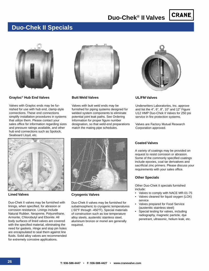
Grayloc® Hub End Valves
Valves with Grayloc ends may be fur-nished for use with hub end, clamp-styleconnections. These end connectionssimplify installation procedures in systemsthat utilize them. Please contact yoursales office for information regarding sizesand pressure ratings available, and otherhub end connections such as Spolock,Seaboard Lloyd, etc.
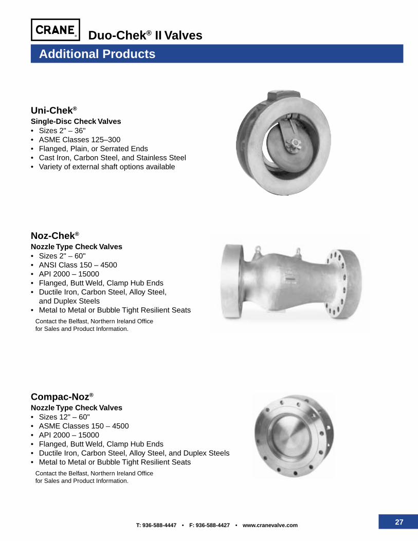
Lined Valves
Duo-Chek II valves may be furnished withlinings, when specified, for abrasion orcorrosion resistance. Linings includeNatural Rubber, Neoprene, Polyurethane,Armorite, Chlorobutyl and Ebonite. Allbody surfaces of lined valves are coveredwith the specified material, eliminating theneed for gaskets. Hinge and stop pin holesare encapsulated to seal them against linefluids. Solid alloy valves are recommendedfor extremely corrosive applications.
Butt Weld Valves
Valves with butt weld ends may befurnished for piping systems designed forwelded system components to eliminatepotential joint leak paths. See OrderingInformation for proper figure numberdesignation, so that weld-end preparationsmatch the mating pipe schedules.
Cryogenic Valves
Duo-Chek II valves may be furnished forsubatmospheric to cryogenic temperatures(-50°F through -450°F). Special materialsof construction such as low temperaturealloy steels, austenitic stainless steel,aluminum bronze or monel are generallyrequired.
UL/FM Valves
Underwriters Laboratories, Inc. approveand list the 4", 6", 8", 10" and 12" FigureU12 HMP Duo-Chek II Valves for 250 psiservice in fire protection systems.
Valves are Factory Mutual ResearchCorporation approved.
27T: 936-588-4447 • F: 936-588-4427 • www.cranevalve.com
Duo-Chek® II Valves
Additional Products
Noz-Chek®
Nozzle Type Check Valves• Sizes 2" – 60"• ANSI Class 150 – 4500• API 2000 – 15000• Flanged, Butt Weld, Clamp Hub Ends• Ductile Iron, Carbon Steel, Alloy Steel,
and Duplex Steels• Metal to Metal or Bubble Tight Resilient Seats
Contact the Belfast, Northern Ireland Officefor Sales and Product Information.
Compac-Noz®
Nozzle Type Check Valves• Sizes 12" – 60"• ASME Classes 150 – 4500• API 2000 – 15000• Flanged, Butt Weld, Clamp Hub Ends• Ductile Iron, Carbon Steel, Alloy Steel, and Duplex Steels• Metal to Metal or Bubble Tight Resilient Seats
Contact the Belfast, Northern Ireland Officefor Sales and Product Information.
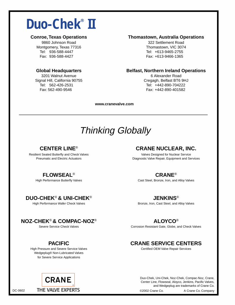
Uni-Chek®
Single-Disc Check Valves• Sizes 2" – 36"• ASME Classes 125–300• Flanged, Plain, or Serrated Ends• Cast Iron, Carbon Steel, and Stainless Steel• Variety of external shaft options available
Duo-Chek® IIConroe, Texas Operations Thomastown, Australia Operations
9860 Johnson Road 322 Settlement RoadMontgomery, Texas 77316 Thomastown, VIC 3074
Tel: 936-588-4447 Tel: +613-9465-2755Fax: 936-588-4427 Fax: +613-9466-1365
Global Headquarters Belfast, Northern Ireland Operations3201 Walnut Avenue 6 Alexander Road
Signal Hill, California 90755 Cregagh, Belfast BT6 9HJTel: 562-426-2531 Tel: +442-890-704222Fax: 562-490-9546 Fax: +442-890-401582
CENTER LINE® CRANE NUCLEAR, INC.Resilient Seated Butterfly and Check Valves Valves Designed for Nuclear Service
Pneumatic and Electric Actuators Diagnostic Valve Repair, Equipment and Services
FLOWSEAL® CRANE®
High Performance Butterfly Valves Cast Steel, Bronze, Iron, and Alloy Valves
DUO-CHEK® & UNI-CHEK® JENKINS®
High Performance Wafer Check Valves Bronze, Iron, Cast Steel, and Alloy Valves
NOZ-CHEK® & COMPAC-NOZ® ALOYCO®
Severe Service Check Valves Corrosion Resistant Gate, Globe, and Check Valves
PACIFIC CRANE SERVICE CENTERSHigh Pressure and Severe Service Valves Certified OEM Valve Repair Services
Wedgeplug® Non-Lubricated Valvesfor Severe Service Applications
Thinking Globally
www.cranevalve.com
DC-0602
Duo-Chek, Uni-Chek, Noz-Chek, Compac-Noz, Crane,Center Line, Flowseal, Aloyco, Jenkins, Pacific Valves,
and Wedgeplug are trademarks of Crane Co.
©2002 Crane Co. A Crane Co. Company