duke h. duncan brewer energy® - nrc.gov · harris nuclear power plant unit 1 (hnp-1) reactor...
TRANSCRIPT

DUKEENERGY®
H. Duncan Brewer Manager, Organizational Effectiveness
Harris NuclearPlant541 3 Shearon Harris Rd New HillNC 27562-9300
Enclosure 2 Contains Proprietary InformationWithhold from Public Disclosure Under 10CFR 2.390 919-362-2305
10CFR50.55aNovember 25, 2013Serial: HNP-13-122
ATTN: Document Control Desk U.S. Nuclear Regulatory Commission Washington, DC 20555-0001
Shearon Harris Nuclear Power Plant, Unit No. 1 Docket No. 50-400
Subject: Relief Request I3R-13, Reactor Vessel Closure Head Nozzle 37, lnservice InspectionProgram- Third Ten-Year IntervalSupporting Calculations
Ladies and Gentlemen:
By letter dated November 22, 2013(Agencywide Documents Access and Management System Accession Number ML 13329A354), Duke Energy Progress, Inc. requested NRCapproval of relief request I3R-13for the Shearon Harris Nuclear Power Plant, Unit 1 (HNP) inservice inspection program, third ten-year interval, pursuant to 10CFR50.55a(a)(3)(i). The enclosed calculations are provided in support of the NRCstaff review of the referenced relief request. Summaries of these calculations were used as justification for the requested relief.
The calculations contain information considered proprietary to AREVA NP Inc. On behalf of AREVA, Duke Energy requests that the NRCwithhold the information in accordance with 10CFR2.390per the enclosed affidavit for withholding proprietary information. Upon removal of the proprietary information, the balance of this letter and enclosures are decontrolled.
This document contains no new regulatory commitments. Please refer any questions regarding this submittal to John Caves at (919) 362-2406.
Sincerely, . ! /
/
1
/ /
H.Duncan Brewer
Enclosures: 1. Affidavit Supporting Withholding of Proprietary Information2. Proprietary Calculations 3. Redacted/Non-Proprietary Calculations
cc: Mr. J. D. Austin , NRCSr. Resident Inspector, HNP Mr. A Hon, NRCProject Manager, HNP Mr. V. M. McCree, NRCRegional Administrator, Region II

HNP-13-122
Shearon Harris Nuclear Power Plant, Unit No. 1
Docket No. 50-400
Relief Request I3R-13, Reactor Vessel Closure Head Nozzle 37
Inservice Inspection Program – Third Ten-Year Interval
Supporting Calculations
Enclosure 1
Affidavit Supporting Withholding of Proprietary Information
AFFIDAVIT
COMMONWEALTHOFVIRGINIA ) ) ss.
CITYOFLYNCHBURG )
1. My name is Gayle F. Elliott. Iam Manager, ProductLicensing, for AREVA
NPInc. (AREVA NP) and as such Iam authorized to execute this Affidavit.
2. Iam familiar with the criteria applied by AREVA NPto determine whether
certain AREVA NPinformation is proprietary. Iam familiar with the policies established by
AREVA NPto ensure the proper application of these criteria.
3. Iam familiar with the AREVA NP information contained in the documents
51-9176114-001, "CorrosionEvaluation of Shearon Harris RV Head Penetration IDTBWeld
Repair,"51-9176115-002, "PWSCCAssessment of the Alloy 600Nozzle in the Shearon Harris
RV Head Penetration IDTBWeld Repair,"32-9176345-002, "ShearonHarris Unit 1 RVCH
CRDM/CET Nozzle IDTBRepair Weld Anomalyand 32-9176350-001,"ShearonHarris Unit 1
CRDM/CET Nozzle As-Left J-groove Weld Analysis," each dated November 2013and referred
to herein as "Documents." Informationcontained in these Documents has been classified by
AREVA NPas proprietary in accordance with the policies established by AREVA NPfor the
control and protection of proprietary and confidential information.
4. These Documents contain information of a proprietary and confidential nature
and is of the type customarily held in confidence by AREVA NPand not made available to the
public. Based on my experience, Iam aware that other companies regard information of the
kind contained in these Documents as proprietary and confidential.

5. These Documents have been made available to the U.S. Nuclear Regulatory
Commission in confidence with the request that the information contained in these Documents
be withheld from public disclosure. The request for withholding of proprietary information is
made in accordance with 10CFR 2.390. The information for which withholding from disclosure
is requested qualifies under 10CFR 2.390(a)(4) "Tradesecrets and commercial or financial
information."
6. The following criteria are customarily applied by AREVA NP to determine
whether information should be classified as proprietary:
(a) The information reveals details of AREVA NP's research and development
plans and programs or their results.
(b) Use of the information by a competitor would permit the competitor to
significantly reduce its expenditures, in time or resources, to design, produce,
or market a similar product or service.
(c) The information includes test data or analytical techniques concerning a
process, methodology, or component, the application of which results in a
competitive advantage for AREVA NP.
(d) The information reveals certain distinguishing aspects of a process,
methodology, or component, the exclusive use of which provides a
competitive advantage for AREVA NP in product optimization or marketability.
(e) The information is vital to a competitive advantage held by AREVA NP, would
be helpful to competitors to AREVA NP, and would likely cause substantial
harm to the competitive position of AREVA NP.
The information in these Documents is considered proprietary for the reasons set forth in
paragraphs 6(c) and 6(d) above.
7. In accordance with AREVA NP's policies governing the protection and control
of information, proprietary information contained in these Documents has been made available,

on a limitedbasis, to others outside AREVA NP onlyas required and under suitableagreement
providing for nondisclosureand limiteduse of the information.
8. AREVA NP policyrequires that proprietary information be kept in a secured
fileor area and distributed on a need-to-know basis.
9. The foregoing statements are true and correct to the best of my knowledge,
information, and belief.
SUBSCRIBEDbefore me this
day of , 2013.
EllaCarr-Payne NOTARYPUBLICSTATEOFVIRGINIAMYCOMMISSIONEXPIRES 8/31/17
R ,,,
MY
,,,,

Enclosure contains proprietary information Withhold from public disclosure under 10 CFR 2.390
HNP-13-122
Shearon Harris Nuclear Power Plant, Unit No. 1
Docket No. 50-400
Relief Request I3R-13, Reactor Vessel Closure Head Nozzle 37
Inservice Inspection Program – Third Ten-Year Interval
Supporting Calculations
Enclosure 2
Proprietary Calculations
AREVA Calculation #32-9176345 Shearon Harris Unit 1 RVCH CRDM/CET Nozzle IDTB Repair Weld Anomaly
AREVA Calculation #32-9176350
Shearon Harris Unit 1 CRDM/CET Nozzle As-Left J-groove Weld Analysis
AREVA Calculation #51-9176114 Corrosion Evaluation of Shearon Harris RV Head Penetration IDTB Weld Repair
AREVA Calculation #51-9176115
PWSCC Assessment of the Alloy 600 Nozzle in the Shearon Harris RV Head Penetration IDTB Weld Repair
HNP-13-122
Shearon Harris Nuclear Power Plant, Unit No. 1
Docket No. 50-400
Relief Request I3R-13, Reactor Vessel Closure Head Nozzle 37
Inservice Inspection Program – Third Ten-Year Interval
Supporting Calculations
Enclosure 3
Redacted/Non-Proprietary Calculations
AREVA Calculation #32- 9215679 Shearon Harris Unit 1 RVCH CRDM/CET Nozzle IDTB Repair Weld Anomaly
AREVA Calculation #32- 9215680
Shearon Harris Unit 1 CRDM/CET Nozzle As-Left J-groove Weld Analysis
AREVA Calculation #51- 9215673 Corrosion Evaluation of Shearon Harris RV Head Penetration IDTB Weld Repair
AREVA Calculation #51- 9215674
PWSCC Assessment of the Alloy 600 Nozzle in the Shearon Harris RV Head Penetration IDTB Weld Repair

Page 1 of 34
0402-01-F01 (Rev. 017, 11/19/12)PROPRIETARY
CALCULATION SUMMARY SHEET (CSS)
Document No. 32 - 9215679 - 000 Safety Related: Yes No
Title Shearon Harris Unit 1 RVCH CRDM/CET Nozzle IDTB Repair Weld Anomaly (Non-Proprietary)
PURPOSE AND SUMMARY OF RESULTS:
AREVA NP Proprietary information in the document are indicated by pairs of brackets “[ ]”.
The purpose of this analysis is to perform fracture mechanics evaluation of a postulated anomaly in the Shearon Harris Nuclear Power Plant Unit 1 (HNP-1) Reactor Vessel Closure Head (RVCH) Control Rod Drive Mechanism (CRDM) / Core Exit Thermocouple (CET) Nozzle contingency modification. According to the design specification document, this anomaly is postulated to be a 0.1 inch flaw extending 360 degrees around the circumference at the “triple point” location where there is a confluence of three materials; the RVCH ferritic steel base metal, the SB-167 Alloy 600 nozzle and the Alloy 52M weld material. Several potential flaw propagation paths are considered in the flaw evaluations. Flaw acceptance is based on the ASME B&PV Code, 2001 with 2002 & 2003 Addenda, Section XI criteria for applied stress intensity factor (IWB-3612) and limit load (IWB-3642).
The results of the analyses demonstrate that the 0.10 inch weld anomaly is acceptable for a 40 year design life of the HNP-1 CRDM/CET Nozzle Repair. The minimum fracture toughness margins for flaw propagation Paths 3 through 6 have been shown to be acceptable as compared to the required margins of √10 for normal/upset conditions and √2 for emergency/faulted (and test) conditions per Section XI, IWB-3612 (Reference [2]). A limit load analysis was performed considering the ductile weld repair material along flaw propagation Path 1 & 2. The analysis showed that for the postulated circumferential flaw the minimum margin on allowable stress is 1.43. For the axial flaw the minimum margin on allowable flaw depth is 3.9. Fracture toughness margins have also been demonstrated for the postulated cylindrical flaws. Also for the cylindrical flaws it is shown that the applied shear stress at the remaining ligament is less than the allowable shear stress per NB-3227.2 [11].
AREVA NP INC. PROPRIETARY
This document and any information contained herein is the property of AREVA NP Inc. (AREVA NP) and is to be considered proprietary and confidential and may not be reproduced or copied in whole or in part. This document shall not be furnished to others without the express written consent of AREVA NP and is not to be used in any way which is or may be detrimental to AREVA NP. This document and any copies that may have been made must be returned to AREVA NP upon request.
THE DOCUMENT CONTAINS ASSUMPTIONS THAT SHALL BE
VERIFIED PRIOR TO USE THE FOLLOWING COMPUTER CODES HAVE BEEN USED IN THIS DOCUMENT:
CODE/VERSION/REV CODE/VERSION/REV
YES NO
AREVACGC 5/0
Controlled Document

Controlled Document
/\ /\ I ~ I ~ VI\
0402-01-F01 (Rev. 01 7, 11/19/1 2) Document No. 32-9215679-000
Shearon Harris Unit 1 RVCH CRDM/CET Nozzle IDTB Repair Weld Anomaly (Non-Proprietary)
Revi evv Meth od: [g) Design Revi ew (Detailed Check) 0 Alternate Calculation
Signature Block
P/R/A Name and Title and
(printed or typed) Signature LP/LR Date Pei-Yuan Cheng
~-,~~~ Engineer III p . t(,h.5(rs Silvester J. Noronha
frOw'~ n!zs(t-, Principal Engineer R
Tim M. Wiger
~%-Unit Manager A \\!~;(: ~~
Note: P/R/A designates Preparer (P), Reviewer (R), Approver (A); LP/LR designates Lead Preparer (LP), Lead Reviewer (LR)
Pages/Sections Prepared/Reviewed/Approved
ALL
ALL
ALL
Project Manager Approval of Customer References (N/A if not applicable)
Name Title (printed or typed) (printed or typed) Signature Date
N/A N/A N/A N/A
Mentoring Information (not required per 0402-01)
Name Title Mentor to: (printed or typed) (printed or typed) (P/R) Signature Date
N/A N/A N/A N/A N/A
Page2

Document No. 32-9215679-000
0402-01-F01 (Rev. 017, 11/19/12)
PROPRIETARY
Shearon Harris Unit 1 RVCH CRDM/CET Nozzle IDTB Repair Weld Anomaly (Non-Proprietary)
Page 3
Record of Revision
Revision No.
Pages/Sections/Paragraphs Changed Brief Description / Change Authorization
000 ALL Original Release. The corresponding proprietary version is in AREVA document 32-9176345-002.
Controlled Document

Document No. 32-9215679-000
PROPRIETARY
Shearon Harris Unit 1 RVCH CRDM/CET Nozzle IDTB Repair Weld Anomaly (Non-Proprietary)
Page 4
Table of Contents
Page
SIGNATURE BLOCK ................................................................................................................................ 2
RECORD OF REVISION .......................................................................................................................... 3
LIST OF TABLES ..................................................................................................................................... 6
LIST OF FIGURES ................................................................................................................................... 7
1.0 INTRODUCTION ........................................................................................................................... 8 1.1 CRD Housing Penetration Modification ............................................................................................ 8 1.2 Potential Weld Anomaly ................................................................................................................... 9 1.3 Postulated Flaws .............................................................................................................................. 9
2.0 ANALYTICAL METHODOLOGY ................................................................................................. 11 2.1 Stress Intensity Factor (SIF) Solutions ........................................................................................... 12 2.2 Fatigue Crack Growth Laws ........................................................................................................... 13 2.3 Fatigue Crack Growth Calculations ................................................................................................ 14 2.4 Acceptance Criteria ........................................................................................................................ 15
3.0 ASSUMPTIONS .......................................................................................................................... 15 3.1 Unverified Assumption ................................................................................................................... 15 3.2 Justified Assumption ...................................................................................................................... 15
4.0 DESIGN INPUTS ........................................................................................................................ 16 4.1 Geometry ........................................................................................................................................ 16 4.2 Material Strength ............................................................................................................................ 17 4.3 Fracture Toughness ....................................................................................................................... 18
4.3.1 Low Alloy Steel RV Head Material ................................................................................... 18 4.3.2 Alloy 52M Material ........................................................................................................... 18
4.4 Applied Stresses Intensity Factor Calculation ................................................................................ 18 4.4.1 Transient Stresses ........................................................................................................... 18 4.4.2 External Loads ................................................................................................................. 19 4.4.3 Residual Stresses ............................................................................................................ 19
5.0 CALCULATIONS ......................................................................................................................... 19 5.1 Circumferential Flaw for Paths 1 & 2 .............................................................................................. 20
5.1.1 Circumferential Flaw Growth Analysis (Paths 1 & 2) ....................................................... 20 5.1.2 Flaw Evaluation for OD Circumferential Flaw (Paths 1 & 2) ............................................ 21
5.2 Axial Flaw for Paths 1 & 2 .............................................................................................................. 21 5.2.1 Axial Flaw Growth Analysis (Paths 1 & 2) ....................................................................... 21 5.2.2 Flaw Evaluation for OD Axial Flaw (Paths 1 & 2) ............................................................ 24
Controlled Document
Document No. 32-9215679-000
PROPRIETARY
Shearon Harris Unit 1 RVCH CRDM/CET Nozzle IDTB Repair Weld Anomaly (Non-Proprietary)
Table of Contents (continued)
Page
Page 5
5.3 Cylindrical Flaw for Paths 3 - 6 ...................................................................................................... 24 5.3.1 Cylindrical Flaw Growth Analysis (Paths 3 – 6) ............................................................... 24 5.3.2 Fracture Toughness Margin for Cylindrical Flaw (Paths 3 – 6) ....................................... 27
6.0 SUMMARY OF RESULTS AND CONCLUSION ......................................................................... 28 6.1 Fatigue Crack Growth of Continuous External Circumferential Flaw ............................................. 28 6.2 Fatigue Crack Growth of Semi-Circular External Axial Flaw .......................................................... 28 6.3 Fatigue Crack Growth of Continuous Cylindrical Flaw along Paths 3 & 5 ..................................... 28 6.4 Fatigue Crack Growth of Continuous Cylindrical Flaw along Paths 4 & 6 ..................................... 29
7.0 COMPUTER USAGE .................................................................................................................. 31 7.1 Validation ........................................................................................................................................ 31 7.2 Computer Files ............................................................................................................................... 31
8.0 REFERENCES ............................................................................................................................ 32
APPENDIX A : VERIFICATION OF SIF FOR CYLINDRICAL FLAW ................................................................ A-1
Controlled Document
Document No. 32-9215679-000
PROPRIETARY
Shearon Harris Unit 1 RVCH CRDM/CET Nozzle IDTB Repair Weld Anomaly (Non-Proprietary)
Page 6
List of Tables
Page
Table 4-1: Material Strength .................................................................................................................. 17 Table 4-2: Load Combinations and Cycles ............................................................................................ 19 Table 5-1: Crack Growth for 360° Circumferential Flaw ........................................................................ 20 Table 5-2: Individual Transient Contribution to Crack Growth for 360° Circumferential Flaw ................ 20 Table 5-3: End of Life Evaluation for Continuous External Circumferential Flaw (Limit Load) .............. 21 Table 5-4: Crack Growth for Axial Flaw ................................................................................................. 22 Table 5-5: Individual Transient Contribution to Crack Growth for Axial Flaw ......................................... 23 Table 5-6: End of Life Evaluation for External Axial Flaw (Limit Load) .................................................. 24 Table 5-7: First year Crack Growth for Cylindrical Flaw along Path 3 ................................................... 25 Table 5-8: First year Crack Growth for Cylindrical Flaw along Path 4 ................................................... 25 Table 5-9: First year Crack Growth for Cylindrical Flaw along Path 5 .................................................... 26 Table 5-10: First year Crack Growth for Cylindrical Flaw along Path 6 ................................................. 26 Table 5-11: Final Crack Depth for Cylindrical Flaw ................................................................................ 27 Table 5-12: LEFM Margin for Cylindrical Flaw ....................................................................................... 27 Table7-1: Computer Files for Crack Growth Evaluation ........................................................................ 31
Controlled Document

Document No. 32-9215679-000
PROPRIETARY
Shearon Harris Unit 1 RVCH CRDM/CET Nozzle IDTB Repair Weld Anomaly (Non-Proprietary)
Page 7
List of Figures
Page
Figure 1-1: Illustration of Crack Propagation Paths ............................................................................... 11 Figure 2-1: OD, Partial Through-Wall, 360° Circumferential Flaw .......................................................... 12 Figure 2-2: OD, Partial Through-Wall, Semi-elliptical Axial Flaw ............................................................ 13
Controlled Document

Document No. 32-9215679-000
PROPRIETARY
Shearon Harris Unit 1 RVCH CRDM/CET Nozzle IDTB Repair Weld Anomaly (Non-Proprietary)
Page 8
1.0 INTRODUCTION
In the Nuclear Power generation industry, SB-167 Alloy 600 Control Rod Drive Mechanism
(CRDM)/Core Exit Thermocouple (CET) nozzle penetrations in the reactor vessel closure head (RVCH)
tends to develop leaks in the region of the partial penetration weld between the RVCH and the
CRDM/CET nozzle. The flaws that lead to leakage are identified to be the result of Primary Water
Stress Corrosion Cracking (PWSCC). Previous mitigation repair processes involved using manual
grinding and welding. The manual repair of these CRDM nozzles defects may result in extensive
radiation dose to the personnel due to the location and access limitations. Commissioned by the B&W
Owners Group (BWOG), AREVA developed an automated repair process. Due to concerns that
PWSCC initiated degradation or defects at the CRDM nozzle and/or Core Exit Thermocouple (CET)
may have occurred at Shearon Harris 1, Progress Energy Service Company, LLC, has contracted
AREVA to adapt this repair for Shearon Harris 1 as a contingency. The specific nozzle penetration(s)
to be modified shall be identified based on a visual, surface, and/or volumetric examination(s) for
CRDM or CET nozzle penetration leakage. The full specification of the repair/modification design is
described in Reference [1].
The purpose of this analysis is to perform fracture mechanics evaluation of a postulated anomaly in the
Shearon Harris Nuclear Power Plant Unit 1 (HNP-1) RVCH Control Rod Drive Mechanism (CRDM) /
Core Exit Thermocouple (CET) Nozzle contingency modification. According to the design specification
document [1], this anomaly is postulated to be a 0.1 inch flaw extending 360 degrees around the
circumference at the “triple point” location where there is a confluence of three materials; the RVCH
ferritic steel base metal, the SB-167 Alloy 600 nozzle and the Alloy 52M weld material. Several
potential flaw propagation paths are considered in the flaw evaluations. Flaw acceptance is based on
the 2001 ASME B&PV Code with 2003 Addenda Section XI criteria [2] for applied stress intensity factor
(IWB-3612) and limit load (IWB-3642).
1.1 CRD Housing Penetration Modification
The CRDM/CET Nozzle modification is described by the design drawing [3]. This modification involves
adding a new weld that will become a part of the pressure boundary. The major steps involved in the
modification design are the following:
• Weld prep machining and NDE
• Welding of repair weld
Controlled Document

Document No. 32-9215679-000
PROPRIETARY
Shearon Harris Unit 1 RVCH CRDM/CET Nozzle IDTB Repair Weld Anomaly (Non-Proprietary)
Page 9
• Machining/grinding and NDE
During the welding process, a maximum 0.1 inch weld anomaly may form due to lack of fusion at the
“triple point”. The anomaly is conservatively postulated to be a “crack-like” defect 360º around the
circumference at the “triple point” location. The design specification document [1] provides additional
details of the weld repair procedure. The purpose of the present fracture mechanics analysis is to
provide justification, in accordance with Section XI of the ASME B&PV Code [2], for operating with the
postulated weld anomaly at the triple point. Predictions of fatigue crack growth are based on a design
life of 40 years.
1.2 Potential Weld Anomaly
The anomaly could be located in the triple point region, the region is called a “triple point” since three
materials intersect at this location. The materials are:
• The CRD housing material, SB-167 – Alloy 600 [1].
• The new weld filler material, ERNiCrFe7A, UNS N06054 [1].
• The RV closure head material, SA-533 Grade B Class 1 [1].
1.3 Postulated Flaws
The triple point weld anomaly is postulated to be semi-circular in shape with an initial depth of 0.1”, as
indicated in [1]. It is further assumed that the anomaly extends 360° around the new repair weld. Three
flaw types are postulated to simulate various orientations and propagation directions for the weld
anomaly. A circumferential flaw and an axial flaw at the outside surface of the new weld would both
propagate in the horizontal direction toward the inside surface of the new weld. A cylindrically oriented
flaw along the interface between the weld and RV closure head would propagate downward between
the two components. The horizontal and vertical flaw propagation directions are represented in Figure
1-1 [4] by separate paths for the downhill and uphill sides of the CRDM/CET Nozzle, as discussed
below. For both these directions, fatigue crack growth will be calculated considering the most
susceptible material for flaw propagation.
Horizontal Direction (Paths 1 and 2):
Flaw propagation is across the CRDM/CET Nozzle wall thickness from the OD to the ID of the
CRDM/CET Nozzle housing. This is the shortest path through the component wall, passing through the
new Alloy 52M weld material [1].
Controlled Document
Document No. 32-9215679-000
PROPRIETARY
Shearon Harris Unit 1 RVCH CRDM/CET Nozzle IDTB Repair Weld Anomaly (Non-Proprietary)
Page 10
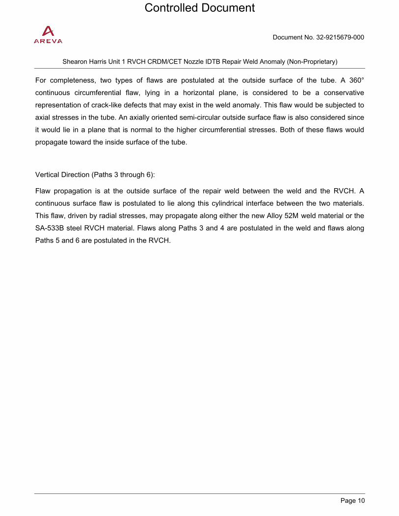
For completeness, two types of flaws are postulated at the outside surface of the tube. A 360°
continuous circumferential flaw, lying in a horizontal plane, is considered to be a conservative
representation of crack-like defects that may exist in the weld anomaly. This flaw would be subjected to
axial stresses in the tube. An axially oriented semi-circular outside surface flaw is also considered since
it would lie in a plane that is normal to the higher circumferential stresses. Both of these flaws would
propagate toward the inside surface of the tube.
Vertical Direction (Paths 3 through 6):
Flaw propagation is at the outside surface of the repair weld between the weld and the RVCH. A
continuous surface flaw is postulated to lie along this cylindrical interface between the two materials.
This flaw, driven by radial stresses, may propagate along either the new Alloy 52M weld material or the
SA-533B steel RVCH material. Flaws along Paths 3 and 4 are postulated in the weld and flaws along
Paths 5 and 6 are postulated in the RVCH.
Controlled Document
Document No. 32-9215679-000
PROPRIETARY
Shearon Harris Unit 1 RVCH CRDM/CET Nozzle IDTB Repair Weld Anomaly (Non-Proprietary)
Page 11
Figure 1-1: Illustration of Crack Propagation Paths
2.0 ANALYTICAL METHODOLOGY
This section presents several aspects of linear elastic fracture mechanics (LEFM) and limit load
analysis (used to address the ductile weld materials) that form the basis of the present flaw evaluations.
As discussed in Section 1.3, flaw evaluations are performed for the flaw propagation paths defined in
Figure 1-1.
Controlled Document

Document No. 32-9215679-000
PROPRIETARY
Shearon Harris Unit 1 RVCH CRDM/CET Nozzle IDTB Repair Weld Anomaly (Non-Proprietary)
Page 12
2.1 Stress Intensity Factor (SIF) Solutions
Three flaw types are postulated for the current evaluation of the weld anomaly defect at the triple point.
For paths 1 and 2 both 360° circumferential and axial surface flaws at the OD of the IDTB weld are
postulated. The solutions for both types of flaws are available in the AREVACGC [5] code which
implements the Stress Intensity Factor (SIF) evaluation for these types of flaws using the weight
function method. AREVACGC performs the fatigue crack growth calculations. The schematics for both
the 360° circumferential and axial flaws postulated at the OD of the IDTB weld are illustrated in Figure
2-1 and Figure 2-2, respectively.
For the vertical paths (3 through 6), a cylindrical flaw is postulated along the interface between the new
repair weld and the RV head material. The potential for flaw propagation along this interface is likely if
radial stresses are significant between the weld and head. This assessment utilizes an SIF solution for
a continuous surface crack in a flat plate from Appendix A Section XI of the ASME B&PV Code [2]. Flat
plate solutions are routinely used to evaluate flaws in cylindrical components such as the repair weld.
The flat plate solution is inherently conservative for this application since the added constraint provided
by the cylindrical structure reduces the crack opening displacements. Crack growth analysis is
performed considering propagation through the Alloy 52M weld metal or the low alloy steel RVCH
material. To facilitate the calculation of the SIF for the cylindrical flaw, a visual basic code, KI_edge,
was developed based on the theory in Appendix A Section XI of the ASME B&PV Code [2] Appendix A
of this document provides verification of the KI_edge visual basic function against hand calculations.
Figure 2-1: OD, Partial Through-Wall, 360° Circumferential Flaw
Controlled Document
Document No. 32-9215679-000
PROPRIETARY
Shearon Harris Unit 1 RVCH CRDM/CET Nozzle IDTB Repair Weld Anomaly (Non-Proprietary)
Page 13
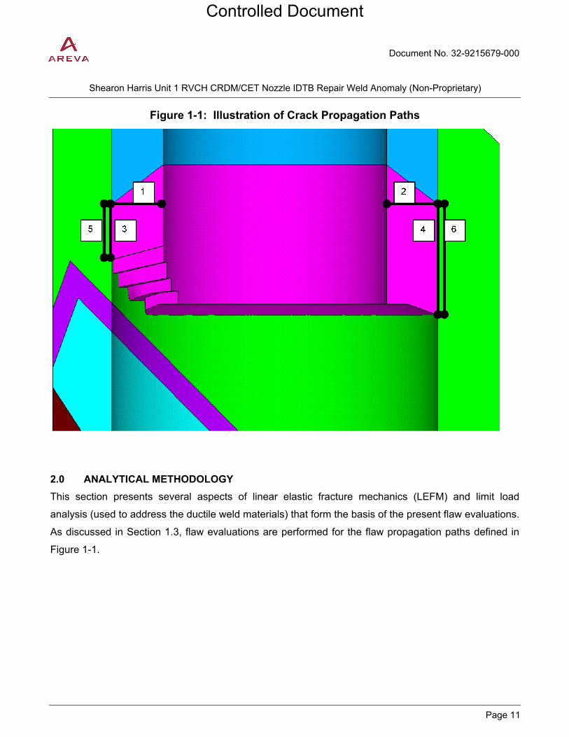
Figure 2-2: OD, Partial Through-Wall, Semi-elliptical Axial Flaw
where, a = initial flaw depth
l = 2c = flaw length
t = wall thickness
2.2 Fatigue Crack Growth Laws
Flaw growth due to fatigue is characterized by
nIo KC
dNda
)(Δ=
where Co and n are constants that depend on the material and environmental conditions, ΔKI is the
range of applied stress intensity factor in terms of ksi√in, and da/dN is the incremental flaw growth in
terms of inches/cycle. For the embedded weld anomaly considered in the present analysis, it is
appropriate to use crack growth rates for an air environment. Fatigue crack growth is also dependent
on the ratio of the minimum to the maximum stress intensity factor; i.e.,
max1min1 )/()(R KK=
SA-533 Grade B Low Alloy Steel Material (RVCH)
From Article A-4300 of the 2001 Edition with 2002 through 2003 Addenda of Section XI [2], the fatigue
crack growth constants for flaws in an air environment are:
n = 3.07
Co = 1.99 × 10⁻¹⁰ S
Flaw Propagation Path
Controlled Document
Document No. 32-9215679-000
PROPRIETARY
Shearon Harris Unit 1 RVCH CRDM/CET Nozzle IDTB Repair Weld Anomaly (Non-Proprietary)
Page 14
S is a scaling parameter to account for the R ratio and is given by S = 25.72 (2.88 − R) − 3.07, where 0 ≤
R ≤ 1 and ΔKI = Kmax − Kmin. For R < 0, ΔKI depends on the crack depth, a, and the flow stress, σf. The
flow stress is defined by σf = ½(σys + σult), where σys is the yield strength and σult is the ultimate tensile
strength. For −2 ≤ R ≤ 0 and Kmax − Kmin ≤ 1.12 σf√πa, S=1 and ΔKI = Kmax. For R < −2 and Kmax − Kmin ≤
1.12 σf√πa, S=1 and ΔKI= (1 − R) Kmax/3. For R < 0 and Kmax − Kmin >1.12 σf√πa, S = 1 and ΔKI = Kmax −
Kmin.
Alloy 52M Weld Metal
Flaw growth in the IDTB Weld (Alloy 52M) and/or Alloy CRDM/CET Nozzle due to cyclic loading is
calculated using the fatigue crack growth model presented in NUREG/CR-6907 [6]. As per reference
[6] a multiplier of 2 is applied to the Alloy 600 crack growth rate. Crack growth analysis is then
conducted on a cycle-by-cycle basis to the end of service life. The crack growth rate equation for Alloy
52M to be used is then given by:
nR KSC
dNda
)(2 Δ=
where ΔK is the stress intensity factor range in terms of MPa√m and da/dN is the crack growth rate in
terms of m/cycle, and
C = 4.835x10⁻¹⁴ + 1.622x10⁻¹⁶T – 1.490x10⁻¹⁸T2 + 4.355x10⁻²¹T3
SR = [1 – 0.82R]-2.2
T = degrees C
R = Kmin / Kmax
2.3 Fatigue Crack Growth Calculations
For the flaw types postulated along paths 1 and 2, the AREVACGC [5] EXCEL based program will be
used to perform the fatigue crack growth calculation and estimate the final flaw size.
For the cylindrical flaw postulated along paths 3 through 6, crack growth was estimated using EXCEL
spread sheets. Crack growth for paths 3 through 6 is calculated by incrementally adding crack growth
for one year at the time. Crack growth for one year is the summation of crack growth due to all
transients for one year. Crack growth is incrementally linked such that the crack growth contribution
from one transient is used to update the crack depth for the subsequent transient.
Controlled Document

Document No. 32-9215679-000
PROPRIETARY
Shearon Harris Unit 1 RVCH CRDM/CET Nozzle IDTB Repair Weld Anomaly (Non-Proprietary)
Page 15
2.4 Acceptance Criteria
For postulated axial and circumferential flaws in the Alloy 52M repair weld the acceptance criteria in
IWB-3642 [2] is used. IWB-3642 [2] states that “piping containing flaws exceeding the acceptance
standards of IWB-3514.1 may be evaluated using analytical procedures described in Appendix C and is
acceptable for continued service during the evaluated time period when the critical flaw parameters
satisfy the criteria in Appendix C.” According to C-4230 [2] for flaws in Ni-Cr-Fe weld metal, flaw
evaluation procedures of C-4210 shall be used. Based on Figure C-4210-1 of Reference [2], for a flaw
in austenitic/Ni-Cr-Fe weld material that uses non-flux welds, Section C-5000 [2] is to be used for flaw
evaluation.
For the postulated cylindrical flaw in the low alloy steel RVCH material and in the Alloy 52M IDTB repair
weld, IWB-3612 acceptance criteria of Section XI [2] is used. According to IWB-3612 a flaw is
acceptable if the applied stress intensity factor for the flaw dimension af satisfy the following criteria.
(a) For normal and upset conditions:
KI < KIa /√10
where
KI = applied stress intensity factor for normal, upset, and test conditions for flaw dimension af.
KIa = fracture toughness based on crack arrest for the corresponding crack-tip temperature
af = end-of-evaluation-period flaw depth
(b) For emergency and faulted conditions:
KI < KIc /√2
KIc = fracture toughness based on crack initiation for the corresponding crack-tip temperature
3.0 ASSUMPTIONS
This section discusses assumptions and modeling simplifications applicable to the present evaluation.
3.1 Unverified Assumption
This document contains no unverified assumptions.
3.2 Justified Assumption
1) The anomaly is postulated to include a “crack-like” defect, located at the “triple-point”
location. For analytical purposes, a continuous circumferential flaw is located in the
horizontal plane. Another continuous flaw is located in the cylindrical plane between the
weld and RVCH.
Controlled Document
Document No. 32-9215679-000
PROPRIETARY
Shearon Harris Unit 1 RVCH CRDM/CET Nozzle IDTB Repair Weld Anomaly (Non-Proprietary)
Page 16
2) In the radial plane, the anomaly is assumed to include a quarter-circular “crack-like”
defect. For analytical purposes, a semi-circular flaw is used to represent the radial cross-
section of the anomaly.
3) In the interface of IDTB weld and RVCH bore, the anomaly is assumed to include a
cylindrical-flaw like defect. For analytical purposes, a flaw in a semi-infinite plate is used
to represent the radial cross-section of the anomaly.
4) Dimensions used for the analyses are based on nominal values. This is considered to be
standard practice in stress analysis and fracture mechanics analysis.
5) The CRDM housing nozzles function as mechanical mounts for the CRDM. The CRDM
are relatively tall, slender structures that may be subjected to seismic or other motions
resulting in bending loads on the ‘CRDM nozzle-to-head connection’ weld. However,
mechanical loads from the CRDM are transmitted to the head through the interference fit
region. The design feature effectively shields the ‘CRDM nozzle-to-head connection’
weld from being subject to external loads. Therefore, external loads are not applicable to
the CRDM/CET nozzle weld repair.
4.0 DESIGN INPUTS
The region of interest for the present flaw evaluations is the triple point, where three different materials
intersect. These materials are the CRDM/CET Nozzle material, the new IDTB repair weld material and
the RVCH material. The HNP-1 CRDM/CET Nozzle is made from SB-167 Alloy 600 material to ASME
specification [1]. The new weld, as noted in Section 1.2, is made from Alloy 52M [1]. The RVCH is
fabricated from SA-533 Grade B Class 1 [1].
4.1 Geometry
Pertinent geometry parameters used for flaw evaluations are provided below:
Paths 1 & 2
The following dimensions are used for evaluating the 360° circumferential flaw and axial flaw postulated
along paths 1 & 2
Controlled Document

Document No. 32-9215679-000
PROPRIETARY
Shearon Harris Unit 1 RVCH CRDM/CET Nozzle IDTB Repair Weld Anomaly (Non-Proprietary)
Page 17
Outside Diameter, Do = [ ] [3]
Inside Diameter, Di = [ ] [3]
Thickness, t = [ ]
Initial flaw depth, ai = 0.1 in [1]
Paths 3 through 6
The cylindrical flaws postulated along paths 3 through 6 propagate along the interface between the
IDTB repair weld and the RV Closure head. The length of this interface at paths 3 and 5 are 0.5 inch
and at paths 4 and 6 are 1.35 inches [3]. The initial flaw depth is postulated to be 0.1 inches [1].
4.2 Material Strength
Reference [9] provides the material strength pertinent for the flaw evaluation assessment of the weld
anomaly in this document. Table 4-1 lists the values of yield strength (σy), ultimate strength (σult), and
the flow strength (σf), taken as the average of the ultimate and yield strengths.
Table 4-1: Material Strength
Material ComponentTemperature
(ºF)
Yield Strength, σy
(ksi)
Ultimate Strength, σult
(ksi)
SA-533 Grade B Class 1
RV Closure Head
Weld Filler Alloy 52M Equivalent SB-166 Alloy 690 properties
IDTB Weld
†Interpolated values, ‡ The correct value for yield strength according to [7] is [ ] , however [ ] gives conservative results.
Controlled Document

Document No. 32-9215679-000
PROPRIETARY
Shearon Harris Unit 1 RVCH CRDM/CET Nozzle IDTB Repair Weld Anomaly (Non-Proprietary)
Page 18
4.3 Fracture Toughness
4.3.1 Low Alloy Steel RV Head Material
The RTNDT for the low alloy steel RVCH is [ ] [8], however a value of [ ] is conservatively used in this calculation. Fracture toughness curves for SA-533 Grade B Class 1 material is illustrated
in Figure A-4200-1 of Reference [2]. At an operating temperature of about [ ] , the KIa fracture
toughness values for this material is (using an assumed RTNDT of [ ] ) are above 200 ksi√in. An upper bound value of 200 ksi√in will be conservatively used for the present flaw evaluations.
4.3.2 Alloy 52M Material
Brittle fracture is not a credible failure mechanism for ductile materials such as Alloy 52M, the failure mechanism for the Alloy 52M materials is limit load or ductile crack extension (EPFM). A value of 200 ksi√in will be conservatively used for the fracture toughness of Alloy 52M. This will be used to evaluate the IWB-3612 acceptance criteria for the cylindrical flaw postulated in the repair weld since a limit load solution is not available in the ASME B&PV Code [2] for such a flaw.
4.4 Applied Stresses Intensity Factor Calculation
As mentioned in Section 2.1, the weight function method implemented in AREVACGC [5] was used to calculate the SIF for the continuous OD circumferential and axial surface flaws. For the cylindrical flaw, the SIF solution given in Appendix A of the 2001 Edition of Section XI [2] was used to calculate the SIF solution.
4.4.1 Transient Stresses
The cyclic operating stresses that are needed to calculate fatigue crack growth are obtained from a thermo-elastic finite element analysis [9]. These cyclic stresses are developed for all the transients at a number of time points to capture the maximum and minimum stresses due to fluctuations in pressure and temperature. Per References [9], the number of RCS design transients is established for 40 years of design life. Cyclic operating stresses were generated in Reference [9] for the transients listed in Reference [10]. The transients that have trivial contribution to fatigue are not considered per Reference [9]. The transient cycle counts used in this calculation are obtained from Reference [10]. The operating transients are listed in Table 4-2.
Controlled Document

Document No. 32-9215679-000
PROPRIETARY
Shearon Harris Unit 1 RVCH CRDM/CET Nozzle IDTB Repair Weld Anomaly (Non-Proprietary)
Page 19
Table 4-2: Load Combinations and Cycles
Service Level
Level A Level A Level A Level A Level A Level A Level A Level B Level B Level B Level B Level B Test Test
4.4.2 External Loads
The CRDM housing nozzles function as mechanical mounts for the CRDM. The CRDM are relatively tall, slender structures that may be subjected to seismic or other motions resulting in bending loads on the ‘CRDM nozzle-to-head connection’ weld. However, mechanical loads from the CRDM are transmitted to the head through the interference fit region. The design feature effectively shields the ‘CRDM nozzle-to-head connection’ weld from being subject to external loads. Therefore, external loads are not applicable to the CRDM/CET nozzle weld repair.
4.4.3 Residual Stresses
A three-dimensional elastic-plastic finite element analysis [4] was performed to simulate the sequence of steps involved in arriving at the configuration of the weld repair of CRDM/CET Nozzle in the RVCH of HNP-1. The residual stress analysis [4] simulated welding of the existing J-groove weld and butter; machining of the CRDM/CET nozzle and IDTB weld prep; welding of the IDTB weld repair with Alloy 52M and final machining. Operation at steady state temperature and pressure conditions and return to zero load conditions was also simulated after the completion of the weld simulation.
5.0 CALCULATIONS
Assessment of a flaw like triple point anomaly in the HNP-1 CRDM/CET Nozzle repair was completed using three flaw types that were postulated to form in the vicinity of the triple point. For every postulated flaw type a crack growth analysis was conducted to determine the final flaw size after 40 years of operation. After the final flaw size is determined, the flaw is assessed to determine the safety margins and compliance with the flaw acceptance criteria outlined in Section 2.4.
Controlled Document

Document No. 32-9215679-000
PROPRIETARY
Shearon Harris Unit 1 RVCH CRDM/CET Nozzle IDTB Repair Weld Anomaly (Non-Proprietary)
Page 20
5.1 Circumferential Flaw for Paths 1 & 2
5.1.1 Circumferential Flaw Growth Analysis (Paths 1 & 2)
AREVACGC [5] was used to determine the final flaw depth due to fatigue crack growth. A summary of the final flaw depths is given in Table 5-1 for paths 1 & 2. Contribution of the individual transients to crack growth is given in Table 5-2.
Table 5-1: Crack Growth for 360° Circumferential Flaw
Path Path1 Path2
Initial Flaw Depth (in) = 0.1000 0.1000 Initial a/t ratio = [ ] [ ]
Final Flaw Depth (in) = [ ] [ ] Final a/t ratio = [ ] [ ]
Total Amount of Fatigue Crack Growth (in) = [ ] [ ]
Table 5-2: Individual Transient Contribution to Crack Growth for 360° Circumferential Flaw
Controlled Document

Document No. 32-9215679-000
PROPRIETARY
Shearon Harris Unit 1 RVCH CRDM/CET Nozzle IDTB Repair Weld Anomaly (Non-Proprietary)
Page 21
5.1.2 Flaw Evaluation for OD Circumferential Flaw (Paths 1 & 2)
As mentioned in Section 2.4, Article C-5000 of Reference [2] contains the appropriate flaw evaluation procedure for the end of life OD circumferential flaw. Since the final flaw depth along path 2 ( [ ] ) is greater than for path 1 ( [ ] ), the final flaw depth for path 2 was used for the end of life flaw evaluation. Table 5-3 shows details of the end of life flaw evaluation analysis performed to assess the postulated continuous circumferential flaw. It is seen from Table 5-3 that the allowable stress is higher than the applied membrane stress by 1.43 times safety factor.
Table 5-3: End of Life Evaluation for Continuous External Circumferential Flaw (Limit Load)
Yield strength, σy = [ ] ksi
Ultimate strength, σu = [ ] ksi
Pressure, p = [ ] psi
Outside Radius, Ro = [ ] in
Inside Radius, Ri = [ ] in
Mean Radius, Rm= [ ] in
Thickness, t = [ ] in
Final Flaw Depth, af = [ ] in
Area of remaining ligament, A=π((Ro-af
)2- (Ri)2) =
[ ] in2
External Load, Pexternal = [ ] lbs
σm=pDo/4t + Pexternal/A = [ ] ksi
Flow strength, σf = [ ] ksi Safety Factor, SFm = 2.7
θ = 3.141593 rad
σmc =σf/[1-(a/t)(θ/π)-2φ/π] = [ ] ksi
φ=arcsin[0.5(a/t)sinθ] = 0 rad
St= σmc/SFm = [ ] ksi
Margin, St/σm = 1.43
5.2 Axial Flaw for Paths 1 & 2
5.2.1 Axial Flaw Growth Analysis (Paths 1 & 2)
AREVACGC [5] was used to determine the final flaw depth due to fatigue crack growth. For each path (1 & 2) crack growth was performed using depth location (radial) and surface location (axial) SIF. A summary of the final flaw depths is given in Table 5-4 for paths 1 & 2. Contribution of the individual transients to crack growth is given in Table 5-5.
Controlled Document

Document No. 32-9215679-000
PROPRIETARY
Shearon Harris Unit 1 RVCH CRDM/CET Nozzle IDTB Repair Weld Anomaly (Non-Proprietary)
Page 22
Table 5-4: Crack Growth for Axial Flaw
Radial Axial
Path Path1 Path2 Path1 Path2
Initial Flaw Depth (in) = 0.1000 0.1000 0.1000 0.1000 Initial a/t ratio = [ ] [ ] [ ] [ ]
Final Flaw Depth (in) = [ ] [ ] [ ] [ ] Final a/t ratio = [ ] [ ] [ ] [ ]
Total Amount of Fatigue Crack Growth (in) = [ ] [ ] [ ] [ ]
Controlled Document

Document No. 32-9215679-000
PROPRIETARY
Shearon Harris Unit 1 RVCH CRDM/CET Nozzle IDTB Repair Weld Anomaly (Non-Proprietary)
Page 23
Table 5-5: Individual Transient Contribution to Crack Growth for Axial Flaw
Controlled Document

Document No. 32-9215679-000
PROPRIETARY
Shearon Harris Unit 1 RVCH CRDM/CET Nozzle IDTB Repair Weld Anomaly (Non-Proprietary)
Page 24
5.2.2 Flaw Evaluation for OD Axial Flaw (Paths 1 & 2)
As mentioned in Section 2.4, Article C-5000 of Reference [2] contains the appropriate flaw evaluation procedure for the end of life OD axial flaw. As shown in Table 5-4 the maximum flaw depth is [ ] for a flaw along path 2 considering an axial crack growth of [ ] . This flaw depth was used for the end of life flaw evaluation of the postulated OD axial flaw. Table 5-6 shows details of the end of life flaw evaluation of the postulated OD axial flaw. It is shown in Table 5-6, that both the final flaw depth and length, after 40 years of crack growth, are less than the allowable flaw depth and length.
Table 5-6: End of Life Evaluation for External Axial Flaw (Limit Load)
Yield strength, σy= [ ] ksi
Ultimate strength, σu= [ ] ksi
Flow strength, σf= [ ] ksi
Pressure, p= [ ] psi
Outside Radius, Ro= [ ] in
Inside Radius, Ri= [ ] in
Mean Radius, Rm= [ ] in
Thickness, t= [ ] in
Final Flaw Depth, af= [ ] in
Final Flaw Length, lf= [ ]
σh=pRm/t= [ ] ksi
lallow=1.58(Rmt)0.5[(σf/σh)2-1]0.5= [ ] in
M2=[1+(1.61 / 4Rmt)lf2)]1/2= [ ]
Safety Factor, SFm= [ ]
Stress Ratio = SFm σh/σf= [ ]
Nondimensional Flaw Length, lf/√Rmt= [ ]
Allowable a/t = [ ] TABLE C-5410-1 Reference [2]
Allowable Flaw Depth, aallow = [ ] > [ ] Margin, aallow/af= 3.9
5.3 Cylindrical Flaw for Paths 3 - 6
5.3.1 Cylindrical Flaw Growth Analysis (Paths 3 – 6)
For the cylindrical flaws, crack growth was calculated in accordance with Section 2.3. Crack growth for
first year is shown in Table 5-7 through Table 5-10 for paths 3 through 6, respectively. Final crack
depths for the cylindrical flaws for all paths are shown in Table 5-11.
Controlled Document

Document No. 32-9215679-000
PROPRIETARY
Shearon Harris Unit 1 RVCH CRDM/CET Nozzle IDTB Repair Weld Anomaly (Non-Proprietary)
Page 25
Table 5-7: First year Crack Growth for Cylindrical Flaw along Path 3
Table 5-8: First year Crack Growth for Cylindrical Flaw along Path 4
Controlled Document

Document No. 32-9215679-000
PROPRIETARY
Shearon Harris Unit 1 RVCH CRDM/CET Nozzle IDTB Repair Weld Anomaly (Non-Proprietary)
Page 26
Table 5-9: First year Crack Growth for Cylindrical Flaw along Path 5
Table 5-10: First year Crack Growth for Cylindrical Flaw along Path 6
Controlled Document

Document No. 32-9215679-000
PROPRIETARY
Shearon Harris Unit 1 RVCH CRDM/CET Nozzle IDTB Repair Weld Anomaly (Non-Proprietary)
Page 27
Table 5-11: Final Crack Depth for Cylindrical Flaw
Crack Depth (in)
Path3 [ ] Path4 [ ] Path5 [ ] Path6 [ ]
5.3.2 Fracture Toughness Margin for Cylindrical Flaw (Paths 3 – 6)
As mentioned in Section 2.4, for the postulated cylindrical flaw in the low alloy steel RV closure head
material and in the IDTB weld (Alloy 52M), IWB-3612 acceptance criteria of Section XI [2] is used.
According to IWB-3612 a flaw is acceptable if the applied stress intensity factor for the flaw dimension
af satisfy the criteria that KI < KIa /√10 for normal/upset conditions and KI < KIc /√2 for emergency/faulted
conditions. To determine the fracture toughness margin, the maximum applied stress intensity factor for
all time points is determined for each flaw path. The effective stress intensity factor is then determined
based on the theory in Reference [2]. The temperature (T) is the minimum (limiting) temperature of
each transient. The minimum temperatures of most limiting transients are shown along with
corresponding KIa’s are shown in Table 5-12. In Table 5-12, it is shown that the calculated minimum
LEFM margins are [ ] for service level A and B and [ ] for Test Conditions, and are thus
higher than the required margin of √10 (Level A & B) and √2 (Level C & D), respectively.
Table 5-12: LEFM Margin for Cylindrical Flaw
Path
Levels A & B
3 (Weld) 4 (Weld) 5 (Head) 6 (Head)
Test
3 (Weld) 4 (Weld) 5 (Head) 6 (Head)
The shear stress at the remaining ligament is also calculated as follows:
Controlled Document

Document No. 32-9215679-000
PROPRIETARY
Shearon Harris Unit 1 RVCH CRDM/CET Nozzle IDTB Repair Weld Anomaly (Non-Proprietary)
Page 28
τ = (Paxial_H + Paxial_E)/(As)
Where Paxial_H = (π/4)⋅P⋅Do2 = (π/4) * [ ] [Ref. 10] * [ ] [Ref. 3] = [ ]
Paxial_E = [ ] [Ref. 10], where As = 2 x π x [(L3,5 + L4,6)/2 x Do/2 ]
Where L3,5 is the remaining ligament of the IDTB weld/head interface after crack growth at path 3 or 5,
and L4,6 is the remaining ligament at path 4 or 6. The maximum crack growth among cracks along
paths 3 through 6 is for path 5 and the final flaw size in case of path 5 is [ . ] Thus the
area of the remaining ligament (approximated as two trapezoids) is found as [
]
Thus the shear stress, τ = (Paxial_H + Paxial_E)/(As) = [ ] (ksi)
Per NB-3227.2 [11], the maximum allowable average primary shear stress in IDTB weld is 0.6Sm, which
equals 13.98 ksi (with Sm equal to 23.3 ksi [9]). Therefore the remaining ligament of the IDTB weld has
a lower shear stress than allowable shear stress.
6.0 SUMMARY OF RESULTS AND CONCLUSION
The flaw evaluation results for 40 years of fatigue crack growth are as follows.
6.1 Fatigue Crack Growth of Continuous External Circumferential Flaw
a) Fatigue crack growth analysis: Initial flaw size, ai = 0.1000 in.
Final flaw size, af = [ ] in. b) End of Life (Limit load) analysis:
Margin, St/σm= 1.43
6.2 Fatigue Crack Growth of Semi-Circular External Axial Flaw
a) Fatigue crack growth analysis: Initial flaw size, ai = 0.100 in.
Final flaw size, af = [ ] in. b) End of Life (Limit load) analysis:
Margin, aallow/af= 3.9
6.3 Fatigue Crack Growth of Continuous Cylindrical Flaw along Paths 3 & 5
RVCH (Path 5) Initial flaw size, ai = 0.1000 in.
Final flaw size, af = [ ] in.
Level A and B Stress intensity factor at final flaw size, KIeff = [ ]
Controlled Document

Document No. 32-9215679-000
PROPRIETARY
Shearon Harris Unit 1 RVCH CRDM/CET Nozzle IDTB Repair Weld Anomaly (Non-Proprietary)
Page 29
Level A and B Fracture toughness KIa = [ ] ksi√in Level A and B Fracture toughness margin, KIa /KIeff = 4.69 > √10
Test Stress intensity factor at final flaw size, KIeff = [ ] ksi√in
Test Fracture toughness KIC = [ ] ksi√in Test Fracture toughness margin, KIC / KIeff =1.50 > √2 CRDM Nozzle/RVCH IDTB Weld (Path 3) Initial flaw size, ai = 0.1000 in.
Final flaw size, af = [ ] in.
Level A and B Stress intensity factor at final flaw size, KIeff = [ ] Level A and B Fracture toughness KIa = [ ] Level A and B Fracture toughness margin, KIa /KIeff = 8.31 > √10
Test Stress intensity factor at final flaw size, KIeff = [ ] Test Fracture toughness KIC = [ ] Test Fracture toughness margin, KIC / KIeff = 4.29 > √2
6.4 Fatigue Crack Growth of Continuous Cylindrical Flaw along Paths 4 & 6
RVCH (Path 6) Initial flaw size, ai = 0.1000 in.
Final flaw size, af = [ ] in.
Level A and B Stress intensity factor at final flaw size, KIeff = [ ] Level A and B Fracture toughness KIa = [ ] Level A and B Fracture toughness margin, KIa /KIeff = 3.67 > √10
Test Stress intensity factor at final flaw size, KIeff = [ ] Test Fracture toughness KIC = [ ] Test Fracture toughness margin, KIC / KIeff = 8.53 > √2 CRDM Nozzle/RVCH IDTB Weld (Path 4) Initial flaw size, ai = 0.1000 in.
Final flaw size, af = [ ] in.
Level A and B Stress intensity factor at final flaw size, KIeff = [ ] Level A and B Fracture toughness KIa = [ ] Level A and B Fracture toughness margin, KIa /KIeff = 10.92 > √10
Controlled Document

Document No. 32-9215679-000
PROPRIETARY
Shearon Harris Unit 1 RVCH CRDM/CET Nozzle IDTB Repair Weld Anomaly (Non-Proprietary)
Page 30
Test Stress intensity factor at final flaw size, KIeff = [ ] Test Fracture toughness KIC = [ ] Test Fracture toughness margin, KIC / KIeff = 11.41 > √2
The results of the analysis demonstrate that a 0.10 inch weld anomaly is acceptable for a 40 year
design life of the HNP-1 CRDM/CET RVCH weld repair. The minimum fracture toughness margins for
flaw propagation Paths 3 through 6 have been shown to be acceptable as compared to the required
margins of √10 for normal/upset conditions and √2 for emergency/faulted (and test) conditions per
Section XI, IWB-3612 (Reference [2]). A limit load analysis was performed considering the ductile weld
repair material along flaw propagation Paths 1 & 2. The analysis showed that for the postulated
circumferential flaw the minimum margin on allowable stress is 1.43. For the axial flaw the minimum
margin on allowable flaw depth is 3.9. Fracture toughness margins have been demonstrated for the
postulated cylindrical flaws. Also for cylindrical flaws it is shown that the applied shear stress at the
remaining ligament is less than the allowable shear stress per NB-3227.2 [11].
Controlled Document

Document No. 32-9215679-000
PROPRIETARY
Shearon Harris Unit 1 RVCH CRDM/CET Nozzle IDTB Repair Weld Anomaly (Non-Proprietary)
Page 31
7.0 COMPUTER USAGE
7.1 Validation
7.2 Computer Files
Table7-1: Computer Files for Crack Growth Evaluation
File Name Date Modified Checksum Description
[ ] 04/19/2012 59637[
]
[ ] 04/14/2012 11300[
]
[ ] 04/14/2012 43994 [ ]
[ ] 04/13/2012 25438 [ ]
[ ] 04/13/2012 46815 [ ]
[ ] 04/13/2012 10737 [ ]
[ ] 6/29/2010 17753[
] [ ] 1/6/2011 41940 [ ]
Controlled Document

Document No. 32-9215679-000
PROPRIETARY
Shearon Harris Unit 1 RVCH CRDM/CET Nozzle IDTB Repair Weld Anomaly (Non-Proprietary)
Page 32
8.0 REFERENCES 1. AREVA NP Document 08- 9172870-002, Design Specification, “Shearon Harris RVCH CRDM
and CET Nozzle Penetration Modification” 2. ASME Boiler and Pressure Vessel Code, Section XI, 2001 Edition with 2003 Addenda, “Rules
for Inservice Inspection of Nuclear Power Plant Components” 3. AREVA NP Drawing 02-9175500E-005, “Shearon Harris CRDM ID Temper Bead Weld Repair” 4. AREVA NP Document 32-9176344-000, “Shearon Harris Unit 1 CRDM/CET Nozzle Weld
Residual Stress Analysis” (Proprietary Document). 5. AREVA NP Document 32-9055891-006, “Fatigue and PWSCC Crack Growth Evaluation Tool
AREVACGC” (Proprietary Document). 6. NUREG/CR-6907, “Crack Growth Rates of Nickel Alloy Welds in a PWR Environment”, U.S.
Nuclear Regulatory Commission (Argonne National Laboratory), May 2006. 7. ASME Boiler and Pressure Vessel Code, 2001 Edition with 2003 Addenda, Section II, Part D,
“Materials Properties” 8. AREVA NP Document 38-2200979-000, “Shearon Harris – Proprietary Document” 9. AREVA NP Document 32-9175220-003, “Shearon Harris Unit 1 Contingency CRDM IDTB Weld
Repair Analysis” 10. AREVA NP Document 38-2201004-000, “Shearon Harris Proprietary Document Transmittal – 4” 11. ASME Boiler and Pressure Vessel Code, Section III, 2001 Edition with 2003 Addenda
Controlled Document

Document No. 32-9215679-000
PROPRIETARY
Shearon Harris Unit 1 RVCH CRDM/CET Nozzle IDTB Repair Weld Anomaly (Non-Proprietary)
Page A-1
APPENDIX A: VERIFICATION OF SIF FOR CYLINDRICAL FLAW
Controlled Document

Document No. 32-9215679-000
PROPRIETARY
Shearon Harris Unit 1 RVCH CRDM/CET Nozzle IDTB Repair Weld Anomaly (Non-Proprietary)
Page A-2
Controlled Document

Page 1 of 88
0402-01-F01 (Rev. 017, 11/19/12)PROPRIETARY
CALCULATION SUMMARY SHEET (CSS)
Document No. 32 - 9215680 - 000 Safety Related: Yes No
Title Shearon Harris Unit 1 CRDM/CET Nozzle As-Left J-groove Weld Analysis (NonProprietary)
PURPOSE AND SUMMARY OF RESULTS:
AREVA NP Proprietary information in the document are indicated by pairs of brackets “ [ ] ”.
Purpose
The purpose of the present fracture mechanics analysis is to determine the suitability of leaving degraded J-groove weld and butter material in the Shearon Harris Unit 1 reactor vessel head following the repair of either a Control Rod Drive Mechanism (CRDM) nozzle or Core Exit Thermocouple (CET) nozzle by the ID temper bead (IDTB) weld procedure. It is postulated that a small flaw in the head would combine with a large stress corrosion crack in the weld and butter to form a radial corner flaw that would propagate into the low alloy steel head by fatigue crack growth under cyclic loading conditions.
Summary of Results
Based on a combination of linear elastic and elastic-plastic fracture mechanics analysis of a postulated remaining flaw in the original Alloy 182 J-groove weld and butter material, a Shearon Harris Unit 1 CRDM or CET nozzle is considered to be acceptable for 30 years of operation following an IDTB weld repair. The controlling loading condition is a large loss of coolant accident, for which it was shown that with safety factors of 3 on primary loads and 1.5 on secondary loads that the applied J-integral (2.359 kips/in) was still less than the J-integral of the low alloy steel head material (2.474 kips/in) at a crack extension of 0.1 inch.
AREVA NP INC. PROPRIETARY
This document and any information contained herein is the property of AREVA NP Inc. (AREVA NP) and is to be considered proprietary and confidential and may not be reproduced or copied in whole or in part. This document shall not be furnished to others without the express written consent of AREVA NP and is not to be used in any way which is or may be detrimental to AREVA NP. This document and any copies that may have been made must be returned to AREVA NP upon request.
THE DOCUMENT CONTAINS ASSUMPTIONS THAT SHALL BE
VERIFIED PRIOR TO USE THE FOLLOWING COMPUTER CODES HAVE BEEN USED IN THIS DOCUMENT:
CODE/VERSION/REV CODE/VERSION/REV
YES NO
ANSYS 12.1
Controlled Document

Controlled Document
0402-01 -F01 (Rev. 01 7, 11/1 9/1 2) Document No. 32-9215680-000
Shearon Harris Unit 1 CRDM/CET Nozzle As-Left J-groove Weld Analysis (NonProp rietary)
Review Method : [:gj Design Rev iew (Deta iled Check) D Alternate Calculation
Signature Block
P/R/A Name and Title and
(printed or typed) Signature LP/LR Date Pei-Yuan Cheng
f~-~~<J Engineer III p ty{--1/3 Silvester J. Noronha
?avv~ nlz~ {l > Principal Engineer R
Tim M. Wiger ~ . .,-/~- 'Yzs-;6 Unit Manager A
(""'} -
Note: P/RIA designates Preparer (P), Reviewer (R), Approver (A); LP/LR designates Lead Preparer (LP), Lead Reviewer (LR)
Pages/Sections Prepared/Reviewed/Approved
ALL
ALL
ALL
Project Manager Approval of Customer References (N/A if not applicable)
Name Title (printed or typed) (printed or typed) Signature Date
N/A N/A N/A N/A
Mentoring Information (not required per 0402-01)
Name Title Mentor to: (printed or typed) (printed or typed) (P/R) Signature Date
N/A N/A N/A N/A N/A
Page 2

Document No. 32-9215680-000
0402-01-F01 (Rev. 017, 11/19/12)
PROPRIETARY
Shearon Harris Unit 1 CRDM/CET Nozzle As-Left J-groove Weld Analysis (NonProprietary)
Page 3
Record of Revision
Revision No.
Pages/Sections/Paragraphs Changed Brief Description / Change Authorization
000 All Original Release. The corresponding proprietary version is in AREVA document 32- 9176350-001.
Controlled Document

Document No. 32-9215680-000
PROPRIETARY
Shearon Harris Unit 1 CRDM/CET Nozzle As-Left J-groove Weld Analysis (NonProprietary)
Page 4
Table of Contents
Page
SIGNATURE BLOCK ................................................................................................................................ 2
RECORD OF REVISION .......................................................................................................................... 3
LIST OF TABLES ..................................................................................................................................... 6
LIST OF FIGURES ................................................................................................................................... 7
1.0 INTRODUCTION ........................................................................................................................... 8
2.0 ANALYTICAL METHODOLOGY ................................................................................................. 10 2.1 Stress Intensity Factor Solution ..................................................................................................... 12
2.1.1 Finite Element Crack Models ........................................................................................... 12 2.1.2 Stress Mapping ................................................................................................................ 12 2.1.3 Crack Growth Considerations .......................................................................................... 15 2.1.4 Plastic Zone Correction ................................................................................................... 15
2.2 Linear Elastic Fracture Mechanics ................................................................................................. 16 2.3 Elastic-Plastic Fracture Mechanics ................................................................................................ 17
2.3.1 Screening Criteria ............................................................................................................ 17 2.3.2 Limit Load Analysis .......................................................................................................... 17 2.3.3 Flaw Stability and Crack Driving Force ............................................................................ 18
3.0 ASSUMPTIONS .......................................................................................................................... 20 3.1 Unverified Assumptions.................................................................................................................. 20 3.2 Justified Assumptions ..................................................................................................................... 20 3.3 Modeling Simplifications ................................................................................................................. 20
4.0 DESIGN INPUTS ........................................................................................................................ 21 4.1 Materials ......................................................................................................................................... 21
4.1.1 Mechanical and Thermal Properties ................................................................................ 21 4.1.2 Toughness Properties ...................................................................................................... 23 4.1.3 Fracture Toughness ......................................................................................................... 23 4.1.4 J-integral Resistance Curve ............................................................................................. 23 4.1.5 Fatigue Crack Growth Rate ............................................................................................. 25
4.2 Basic Geometry .............................................................................................................................. 26 4.3 Operating Transients ...................................................................................................................... 26 4.4 Applied Stresses ............................................................................................................................ 28
4.4.1 Residual Stresses ............................................................................................................ 28 4.4.2 Operating Stresses .......................................................................................................... 28
5.0 COMPUTER USAGE .................................................................................................................. 29
Controlled Document
Document No. 32-9215680-000
PROPRIETARY
Shearon Harris Unit 1 CRDM/CET Nozzle As-Left J-groove Weld Analysis (NonProprietary)
Table of Contents (continued)
Page
Page 5
5.1 Hardware/Software ......................................................................................................................... 29 5.2 Installation/Validation Test ............................................................................................................. 29 5.3 Computer Files ............................................................................................................................... 31
6.0 CALCULATIONS ......................................................................................................................... 35 6.1 Initial Flaw Size .............................................................................................................................. 35 6.2 Fatigue Crack Growth .................................................................................................................... 35 6.3 LEFM Flaw Evaluations .................................................................................................................. 39
6.3.1 Normal and Upset Conditions .......................................................................................... 39 6.3.2 Faulted Conditions ........................................................................................................... 40
6.4 EPFM Flaw Evaluations ................................................................................................................. 41 6.4.1 Operating Conditions ....................................................................................................... 41 6.4.2 Low Temperature Conditions ........................................................................................... 43 6.4.3 Faulted Conditions ........................................................................................................... 45
6.5 Limit Load Analysis ........................................................................................................................ 47
7.0 SUMMARY OF RESULTS AND CONCLUSIONS ....................................................................... 48 7.1 Summary of Results ....................................................................................................................... 48 7.2 Conclusion ...................................................................................................................................... 49
8.0 REFERENCES ............................................................................................................................ 49
APPENDIX A : DETAILED FLAW EVALUATIONS FOR UPHILL SIDE ............................................................. 51
APPENDIX B : DETAILED FLAW EVALUATIONS FOR DOWNHILL SIDE ....................................................... 69
Controlled Document

Document No. 32-9215680-000
PROPRIETARY
Shearon Harris Unit 1 CRDM/CET Nozzle As-Left J-groove Weld Analysis (NonProprietary)
Page 6
List of Tables
Page
Table 1-1: Safety Factors for Flaw Acceptance ....................................................................................... 9 Table 4-1: Material Properties for Head ................................................................................................. 21 Table 4-2: Material Properties for Weld Metal ....................................................................................... 22 Table 4-3: Material Properties for Cladding ........................................................................................... 22 Table 4-4: Bounding Transients for Normal and Upset Conditions ........................................................ 27 Table 4-5: Emergency and Faulted Condition Transients ...................................................................... 27 Table 5-1: Test Case Results ................................................................................................................ 30 Table 6-1: LEFM Fracture Toughness Margins for Uphill Side .............................................................. 37 Table 6-2: LEFM Fracture Toughness Margins for Downhill Side ......................................................... 38
Controlled Document

Document No. 32-9215680-000
PROPRIETARY
Shearon Harris Unit 1 CRDM/CET Nozzle As-Left J-groove Weld Analysis (NonProprietary)
Page 7
List of Figures
Page
Figure 1-1: ID Temper Bead Weld Repair ............................................................................................... 8 Figure 2-1: Postulated Radial Flaw on Uphill Side ................................................................................. 11 Figure 2-2: Postulated Radial Flaw on Downhill Side ............................................................................ 11 Figure 2-3: Finite Element Crack Model – Uphill Side ........................................................................... 13 Figure 2-4: Finite Element Crack Model – Downhill Side ....................................................................... 14 Figure 4-1: Correlation of Coefficient, C, of Power Law with Charpy V-Notch Upper Shelf Energy ...... 24 Figure 4-2: Correlation of Exponent, m, of Power Law with Coefficient, C, and Flow Stress, σo ........... 24
Controlled Document

Document No. 32-9215680-000
PROPRIETARY
Shearon Harris Unit 1 CRDM/CET Nozzle As-Left J-groove Weld Analysis
Page 8
1.0 INTRODUCTION
Due to the susceptibility of Alloy 600 partial penetration nozzles to primary water stress corrosion cracking (PWSCC), the Progress Energy plans to inspect the Control Rod Drive Mechanism (CRDM) and Core Exit Thermocouple (CET) nozzles in the Shearon Harris Unit 1 reactor vessel head. In the event that a repair is necessary, an ID temper bead weld repair procedure has been developed wherein the lower portion of the nozzle is removed by a boring procedure and the remaining portion is welded to the low alloy steel reactor vessel head above the original Alloy 82/182 J-groove attachment weld. The repair concept is illustrated in Figure 1-1, both with and without an overlap between the original J-groove weld and the new IDTB weld. The IDTB repair is more fully described by the design drawing [1] and the technical requirements document [2]. Since a potential flaw in the J-groove weld cannot be sized by currently available non-destructive examination techniques, it is assumed that the “as-left” condition of the remaining J-groove weld includes degraded or cracked weld material extending through the entire J-groove weld and Alloy 82/182 butter material.
(a) With Weld Overlap (b) With Overlap Removed
Figure 1-1: ID Temper Bead Weld Repair
Controlled Document

Document No. 32-9215680-000
PROPRIETARY
Shearon Harris Unit 1 CRDM/CET Nozzle As-Left J-groove Weld Analysis
Page 9
Since it is known from the residual stress analysis of the Shearon Harris reactor vessel head outermost nozzle penetration [3] that the hoop stress in the J-groove weld is greater than the axial stress at the same location, the preferential direction for cracking would be axial, or radial relative to the nozzle. It is postulated that a radial crack in the Alloy 82/182 weld metal would propagate by PWSCC, through the weld and butter, to the interface with the low alloy steel head material, where it is fully expected that such a crack would then blunt, or arrest, as discussed in Reference [4]. Since the vertical distance along the bored surface between the inside corner of the remnant J-groove weld and the point where the butter meets the head is more than two inches, a crack extending from the corner of the weld to the low alloy steel head would be very deep. Although primary water stress corrosion cracking would not extend into the head, it is further postulated that a small fatigue initiated flaw forms in the low alloy steel head and combines with the stress corrosion crack in the weld to form a large radial corner flaw that would propagate into the head by fatigue crack growth under cyclic loading conditions. Linear-elastic (LEFM) and elastic-plastic (EPFM) fracture mechanics procedures are utilized to evaluate this worst case flaw in the original J-groove weld and butter.
Key features of the fracture mechanics analysis are:
• This analysis applies specifically to the CRDM nozzle penetrations in the Shearon Harris Unit 1 reactor vessel closure head. A J-integral resistance curve is developed based on the Charpy V-notch upper-shelf energy for the Shearon Harris Unit 1 head plate material.
• Flaw growth is calculated for a 30 year period of operation, corresponding to 20 18-month fuel cycles.
• Final flaw acceptance is based on the available fracture toughness and ductile tearing resistance of the RVCH material considering the safety factors listed in Table 1-1.
• Since the same design is used at Shearon Harris Unit 1 for both the CRDM and CET nozzles and the CET nozzles are located within the same outermost penetration “circle” as the CRDM nozzles, the analysis performed herein for the CRDM nozzles is also applicable to the CET nozzles.
Table 1-1: Safety Factors for Flaw Acceptance
Linear-Elastic Fracture Mechanics
Operating Condition Evaluation Method Fracture Toughness / KI
Normal/Upset KIa fracture toughness √10 = 3.16
Emergency/Faulted KIc fracture toughness √2 = 1.41
Elastic-Plastic Fracture Mechanics
Operating Condition Evaluation Method Primary Secondary
Normal/Upset J/T based flaw stability 3.0 1.5
Normal/Upset J0.1 limited flaw extension 1.5 1.0
Emergency/Faulted J/T based flaw stability 1.5 1.0
Emergency/Faulted J0.1 limited flaw extension 1.5 1.0
Controlled Document

Document No. 32-9215680-000
PROPRIETARY
Shearon Harris Unit 1 CRDM/CET Nozzle As-Left J-groove Weld Analysis
Page 10
2.0 ANALYTICAL METHODOLOGY
A radial flaw at the inside corner of non-radial head penetration is evaluated based on a combination of linear elastic fracture mechanics (LEFM) and elastic-plastic fracture mechanics (EPFM), as outlined below.
1. Postulate radial flaws in the J-groove weld, extending from the inside corner of the penetration to the interface between the butter and head, as shown in Figure 2-1 and Figure 2-2 for the uphill and downhill sides of the penetration, respectively. Initial flaw size, ao, is arbitrarily characterized by the vertical distance along the uphill side penetration bore, from the inside surface of the cladding to the weld-to-butter/head interface, as shown Figure 2-1. For the “constant depth” J-groove design used for the Shearon Harris head, this same flaw depth is also used for the downhill side flaw evaluations.
2. Develop finite element models of the reactor vessel head in the vicinity of the outermost nozzle penetration, with crack tip elements along the interface between the Alloy 82/182 butter and the low alloy steel base metal. These models will be used to obtain stress intensity factors at various positions along the crack front for linearly superimposed residual and operating stresses.
3. Develop a mapping procedure to transfer stresses from an uncracked finite element stress model to the crack face of each crack model. This will enable stress intensity factors to be calculated for arbitrary stress distributions over the crack face utilizing the principle of superposition.
4. Calculate fatigue crack growth, in one year increments, for cyclic loading conditions using operational stresses from pressure and thermal loads. Since the stresses used in the fatigue crack growth analysis are the combined residual plus operating stresses, the effect of the residual stresses on fatigue crack growth is captured by the R ratio, or Kmin/Kmax. Starting from the stress intensity factor calculated by the finite element crack model for the initial flaw size, stress intensity factors are updated for each increment of crack growth by the square root of the flaw size.
5. Utilize the screening criteria of ASME Code Section XI, Appendix C to determine the failure mode and appropriate method of analysis (LEFM, EPFM, or limit load) for flaws in ferritic materials, considering the applied stress, temperature, and material toughness. For LEFM flaw evaluations, compare the stress intensity factor at the final flaw size to the available fracture toughness, with appropriate safety factors, as discussed in Section 2.2. When the material is more ductile and EPFM is the appropriate analysis method, evaluate flaw stability and crack driving force as described in Section 2.3. A limit load analysis would be performed to satisfy the primary stress limits of the ASME Code, as described in Section 2.3.2.
Controlled Document

Document No. 32-9215680-000
PROPRIETARY
Shearon Harris Unit 1 CRDM/CET Nozzle As-Left J-groove Weld Analysis
Page 11
Figure 2-1: Postulated Radial Flaw on Uphill Side
Figure 2-2: Postulated Radial Flaw on Downhill Side
Controlled Document

Document No. 32-9215680-000
PROPRIETARY
Shearon Harris Unit 1 CRDM/CET Nozzle As-Left J-groove Weld Analysis
Page 12
2.1 Stress Intensity Factor Solution
Stress intensity factors for corner flaws at a non-radial nozzle penetration are best determined by finite element analysis using three-dimensional models with crack tip elements along the crack front. Although loads can be applied to finite element crack models like any other structural model, the crack models were developed to serve as a flaw evaluation tool that could accept stresses from separate stress analyses. This strategy makes it possible, for example, to obtain pressure and thermal stresses from an independent thermal/structural analysis and then transfer these stresses to a crack model for flaw evaluations. Using the principle of superposition common to fracture mechanics analysis, the only stresses that need be considered for these flaw evaluations are the stresses on the crack face. A mapping procedure is developed to transfer stresses from a separate stress analysis to the crack face of the crack model.
2.1.1 Finite Element Crack Models
Three-dimensional finite element models are developed for the reactor vessel head in the vicinity of the outermost nozzle penetration, by modeling a portion of the head, cladding, and butter with the ANSYS finite element computer program [5]. Since stresses increase with penetration angle, it is conservative to base the finite element models on the outermost nozzle penetration.
A three-dimensional finite element model is first constructed to represent an unflawed non-radial nozzle penetration in the reactor vessel head using the ANSYS SOLID186 20-node structural element. Elements along the crack front are then replaced by a sub-model of crack tip elements along the interface between the Alloy 82/182 butter and the low alloy steel base metal. These elements consist of 20-node isoparametric elements that are collapsed to form a wedge with the appropriate mid-side nodes shifted to quarter-point locations to simulate the singularity at the crack tip. The final crack models are shown in Figure 2-3 and Figure 2-4 for the uphill and downhill sides of the nozzle, respectively.
Stress intensity factors will be obtained using the ANSYS CINT contour integral procedure at 17 positions along each crack front, as indicated in Figure 2-3 and Figure 2-4 for the two crack models. Position 1 is located on the cladding surface, Position 3 at the cladding/base metal interface, Position 11 at the “kink” in the crack profile, and Position 17 is at the bored surface in the head.
2.1.2 Stress Mapping
Stresses from the finite element stress model are mapped onto the crack faces of the uphill and downhill finite element crack models (Figure 2-3 and Figure 2-4). An ANSYS scripting language instruction (macro) has been developed to query the residual and operating stress models for nodal locations associated with each crack face node of the crack model. The nodal stress from the stress model is then transferred to the corresponding node on the crack model.
Controlled Document
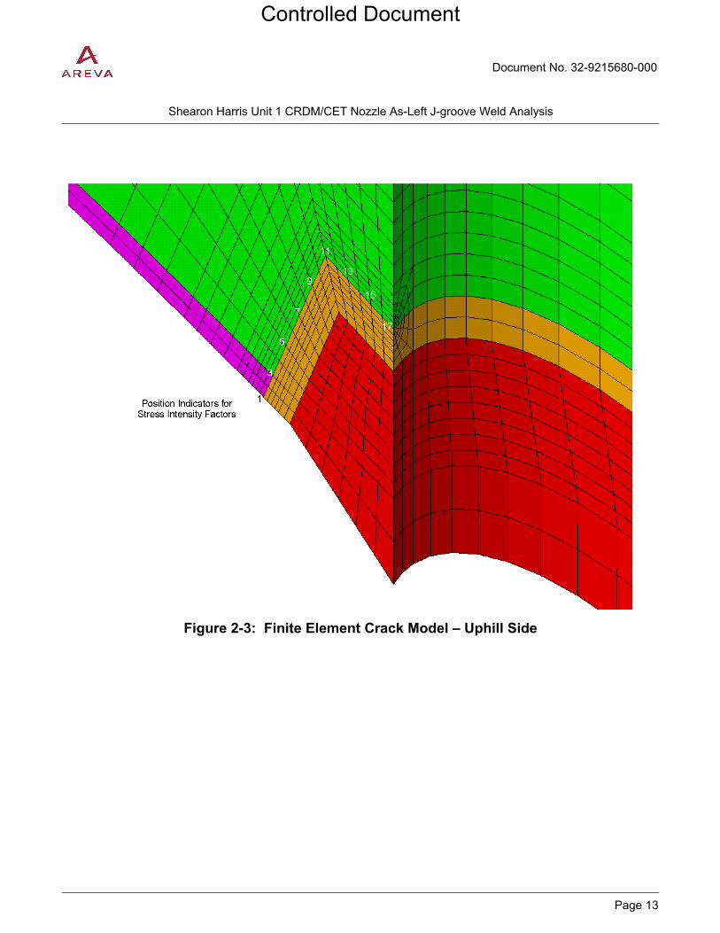
Document No. 32-9215680-000
PROPRIETARY
Shearon Harris Unit 1 CRDM/CET Nozzle As-Left J-groove Weld Analysis
Page 13
Figure 2-3: Finite Element Crack Model – Uphill Side
Controlled Document

Document No. 32-9215680-000
PROPRIETARY
Shearon Harris Unit 1 CRDM/CET Nozzle As-Left J-groove Weld Analysis
Page 14
Figure 2-4: Finite Element Crack Model – Downhill Side
Controlled Document

Document No. 32-9215680-000
PROPRIETARY
Shearon Harris Unit 1 CRDM/CET Nozzle As-Left J-groove Weld Analysis
Page 15
2.1.3 Crack Growth Considerations
The fundamental expression for the crack tip stress intensity factor is
IK = aπσ
Since each crack model is developed for a single flaw size, stress intensity factors are updated at each increment of crack growth by the square root of the flaw size; i.e.,
)a(K 1iI + = i
1iiI a
a)a(K + ,
where a = flaw size
i = increment of crack growth.
Since the stress intensity factor is directly proportional to the magnitude of the stress and both residual and operating stresses decrease in the direction of crack growth, this procedure produces conservative estimates of stress intensity factor as the crack extends into the head and stresses diminish over the expanding crack face.
2.1.4 Plastic Zone Correction
The Irwin plasticity correction is used to account for a moderate amount of yielding at the crack tip. For plane strain conditions, this correction is
2
y
Iy
)a(K
6
1r
σπ= , [ Ref. 6, Eqn. (2.63) ]
where )a(KI = stress intensity factor based on the actual crack size, a
yσ = material yield strength.
A stress intensity factor, )a(K eI , is then calculated for an effective crack size,
ye raa += ,
based on the same scaling technique utilized for crack growth; i.e,
( ) ( )a
aaKaK e
IeI = .
Controlled Document

Document No. 32-9215680-000
PROPRIETARY
Shearon Harris Unit 1 CRDM/CET Nozzle As-Left J-groove Weld Analysis
Page 16
2.2 Linear Elastic Fracture Mechanics
Section XI, Article IWB-3612 [11] requires that the applied stress intensity factor, KI, at the final flaw size be less than the available fracture toughness at the crack tip temperature, with appropriate safety factors, as outlined below.
Normal Conditions: 10/KK IaI <
where KIa is the fracture toughness based on crack arrest.
Faulted Conditions: 2/KK IcI <
where KIc is the fracture toughness based on crack initiation.
Section XI, Article IWB-3613 [11] provides alternate fracture toughness requirements for shell regions near structural discontinuities, such as nozzle penetrations, when the pressure does not exceed 20% of the design pressure and the temperature is not less than RTNDT + 60 °F. Within these operational limits a lower safety factor may be used to evaluate fracture toughness margin. For the Shearon Harris Unit 1
reactor vessel head, the design pressure is [ ] psig [13] and the fracture toughness reference
temperature is [ ] [9]. Thus for pressures at or below [ ] psig and crack tip temperatures at
or above [ ] the acceptance criterion for applied stress intensity factor is as follows:
At pressures ≤ [ ] psig and temperatures ≥ [ ]
2/KK IaI <
Controlled Document

Document No. 32-9215680-000
PROPRIETARY
Shearon Harris Unit 1 CRDM/CET Nozzle As-Left J-groove Weld Analysis
Page 17
2.3 Elastic-Plastic Fracture Mechanics
Elastic-plastic fracture mechanics (EPFM) will be used as alterative acceptance criteria when the flaw related failure mechanism is unstable ductile tearing. This type of failure falls between rapid, non-ductile crack extension and plastic collapse. Linear elastic fracture mechanics (LEFM) would be used to assess the potential for non-ductile failure, whereas limit load analysis would be used to check for plastic collapse.
2.3.1 Screening Criteria
Screening criteria for determining failure modes in ferritic materials may be found in Appendix C of Section XI. Although Appendix C, Article C-4221 [11] contains specific rules for evaluating flaws in Class 1 ferritic piping, its screening criteria may be adapted to other ferritic components, such as the reactor vessel head, as follows:
Let, Kr’ = KIapp / KIc
Sr’ = σmax / σf
Then the appropriate method of analysis is determined by the following limits:
LEFM Regime: Kr’ / Sr’ ≥ 1.8
EPFM Regime: 1.8 > Kr’ / Sr’ ≥ 0.2
Limit Load Regime: 0.2 > Kr’ / Sr’
2.3.2 Limit Load Analysis
While in most instances the screening criteria identify EPFM as the appropriate method of analysis, there are cases where low stress intensity factors (Kr’) relative to the applied stress (Sr’) places the analysis in the limit load regime. Such cases are analyzed through consideration of the primary stress limits of ASME Code Section III as embodied in the equation in Article NB-3324 [7] for the minimum required thickness (tmin) of the spherical closure head,
m
omin S2
PRt = ,
where P = design pressure, [ ] psig [13]
Ro = outside radius, [ ] [1]
Sm = design stress intensity, 26.7 ksi [12]
A conservative limit load analysis would be to limit the remaining net-section of the head after “removal” of the final volume of weld material (after fatigue crack growth) to the minimum required design thickness, tmin. This is equivalent to removing a uniform depth of material along the inner surface of the vessel to encompass the final flaw and comparing the remaining thickness to
mint = 3.74 in.
Controlled Document

Document No. 32-9215680-000
PROPRIETARY
Shearon Harris Unit 1 CRDM/CET Nozzle As-Left J-groove Weld Analysis
Page 18
2.3.3 Flaw Stability and Crack Driving Force
Elastic-plastic fracture mechanics analysis will be performed using a J-integral/tearing modulus (J-T) diagram to evaluate flaw stability under ductile tearing, where J is either the applied (Japp) or the material (Jmat) J-integral, and T is the tearing modulus, defined as (E/σf
2)(dJ/da). The crack driving force, as measured by Japp, is also checked against the J-R curve at a crack extension of 0.1 inch (J0.1). Consistent with industry practice for the evaluation of flaws in partial penetration welds used to attach nozzles to vessels, different safety factors will be utilized for primary and secondary loads. Flaw stability assessments for normal and upset conditions will consider a safety factor of 3 on the stress intensity factor due to primary (pressure) stresses and a safety factor of 1.5 for secondary (residual plus thermal) stresses. The crack driving force will be calculated using safety factors of 1.5 and 1 for primary and secondary stresses, respectively. For EPFM analysis of faulted conditions, safety factors of 1.5 and 1 will be used for flaw stability assessments and 1.5 and 1 for evaluations of crack driving force.
The general methodology for performing an EPFM analyses is outlined below.
Let E’ = E/(1-ν2)
Final flaw depth = a
Total applied KI = KIapp
KI due to pressure (primary) = KIp
KI due to residual plus thermal (secondary) = KIs = KIapp – KIp
Safety factor on primary loads = SFp
Safety factor on secondary loads = SFs
For small scale yielding at the crack tip, a plastic zone correction is used to calculate an effective flaw depth based on
ae = a + [1/(6π)] [ (KIp + KIs) / σy ]2,
which is used to update the stress intensity factors based on
Ip'K = a
aK e
Ip
and Is'K = a
aK e
Is .
The applied J-integral is then calculated using the relationship
Japp = (SFp*K’Ip + SFs*K’Is)2/E’.
Controlled Document

Document No. 32-9215680-000
PROPRIETARY
Shearon Harris Unit 1 CRDM/CET Nozzle As-Left J-groove Weld Analysis
Page 19
The final parameter needed to construct the J-T diagram is the tearing modulus. The applied tearing modulus, Tapp, is calculated by numerical differentiation for small increments of crack size (da) about the final crack size (a), according to
−−+
σ=
)da(2
)daa(J)daa(JET
appapp
2f
app .
Using the power law expression for the J-R curve,
JR = C(Δa)m ,
the material tearing modulus, Tmat, can be expressed as
Tmat = (E/σf2)Cm(Δa)m-1.
Constructing the J-T diagram,
flaw stability is demonstrated at an applied J-integral when the applied tearing modulus is less than the material tearing modulus. Alternately, the applied J-integral is less than the J-integral at the point of instability.
To complete the EPFM analysis, it must be shown that the applied J-integral is less than J0.1, demonstrating that the crack driving force falls below the J-R curve at a crack extension of 0.1 inch.
J
T
Unstable Region Tapp ≥ Tmat
Stable Region Tapp < Tmat
Material
Applied
Instability Point
Controlled Document

Document No. 32-9215680-000
PROPRIETARY
Shearon Harris Unit 1 CRDM/CET Nozzle As-Left J-groove Weld Analysis
Page 20
3.0 ASSUMPTIONS
This section discusses assumptions and modeling simplifications applicable to the present analysis.
3.1 Unverified Assumptions
This analysis contains no assumptions that must be verified prior to use on safety-related work.
3.2 Justified Assumptions
The austenitic cladding is assumed to be adequately represented by 18Cr-8Ni (Type 304) stainless steel material.
The size of the J-groove weld prep and the thickness of the buttering are based on nominal dimensions. This is considered to be standard practice in stress analysis and fracture mechanics analysis. It is conservatively assumed that the postulated flaw extends through the entire J-groove weld and butter.
3.3 Modeling Simplifications
The finite element computer models used to generate residual stresses do not include the ID temper bead repair weld. This is deemed to be an appropriate modeling simplification since compressive stresses induced in the material adjacent to the repair weld would lower stresses on the uphill side of the J-groove weld (in close proximity to the repair weld) and have negligible effect on the downhill side of the J-groove weld (far removed from the repair weld).
Controlled Document

Document No. 32-9215680-000
PROPRIETARY
Shearon Harris Unit 1 CRDM/CET Nozzle As-Left J-groove Weld Analysis
Page 21
4.0 DESIGN INPUTS
This section provides basic input data needed to perform a fatigue crack growth analysis and a flaw evaluation of the final flaw size.
4.1 Materials
4.1.1 Mechanical and Thermal Properties
Table 4-1, Table 4-2, and Table 4-3 list the temperature dependent values of modulus of elasticity (E), Poisson’s ratio (ν), and coefficient of thermal expansion (α) properties used in the finite element crack models. These properties are obtained from the ASME Code, Section II [8], except for Poisson’s ratio, where 0.3 is a typical value used in structural analysis. The flow stress in Table 4-1 is the average of the yield and ultimate strengths.
Component Material
Head SA-533, Grade B Class 1 [Ref. 2, Par. 6.1.1] Cladding use Type 304 stainless steel (SA-240) J-groove weld filler Equivalent to Alloy 600, SB-167 [Ref. 2, Par. 6.1.5] J-groove weld butter use Alloy 600, SB-167
Table 4-1: Material Properties for Head
Component Head
Material SA-533 Grade B Class 1 (Mn-1/2Mo-1/2Ni)
Temperature E (106 psi) ν α (10-6 in./in./oF) σy (ksi) σu (ksi) σf (ksi)
70 29.20 0.3 7.0 50.0 80.0 65.0
100 29.04 0.3 7.1 50.0 80.0 65.0
150 28.77 0.3 7.2 48.1 80.0 64.1
200 28.50 0.3 7.3 47.0 80.0 63.5
250 28.25 0.3 7.3 46.2 80.0 63.1
300 28.00 0.3 7.4 45.5 80.0 62.8
350 27.70 0.3 7.5 44.9 80.0 62.4
400 27.40 0.3 7.6 44.2 80.0 62.1
450 27.20 0.3 7.6 43.7 80.0 61.9
500 27.00 0.3 7.7 43.2 80.0 61.6
550 26.70 0.3 7.8 42.7 80.0 61.3
600 26.40 0.3 7.8 42.1 80.0 61.1
650 25.85 0.3 7.9 41.5 80.0 60.8
700 25.30 0.3 7.9 40.7 80.0 60.4
Controlled Document
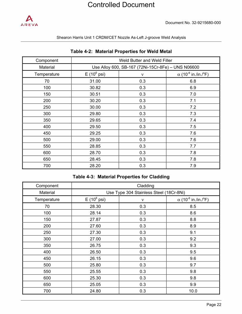
Document No. 32-9215680-000
PROPRIETARY
Shearon Harris Unit 1 CRDM/CET Nozzle As-Left J-groove Weld Analysis
Page 22
Table 4-2: Material Properties for Weld Metal
Component Weld Butter and Weld Filler
Material Use Alloy 600, SB-167 (72Ni-15Cr-8Fe) – UNS N06600
Temperature E (106 psi) ν α (10-6 in./in./oF)
70 31.00 0.3 6.8
100 30.82 0.3 6.9
150 30.51 0.3 7.0
200 30.20 0.3 7.1
250 30.00 0.3 7.2
300 29.80 0.3 7.3
350 29.65 0.3 7.4
400 29.50 0.3 7.5
450 29.25 0.3 7.6
500 29.00 0.3 7.6
550 28.85 0.3 7.7
600 28.70 0.3 7.8
650 28.45 0.3 7.8
700 28.20 0.3 7.9
Table 4-3: Material Properties for Cladding
Component Cladding
Material Use Type 304 Stainless Steel (18Cr-8Ni)
Temperature E (106 psi) ν α (10-6 in./in./oF)
70 28.30 0.3 8.5
100 28.14 0.3 8.6
150 27.87 0.3 8.8
200 27.60 0.3 8.9
250 27.30 0.3 9.1
300 27.00 0.3 9.2
350 26.75 0.3 9.3
400 26.50 0.3 9.5
450 26.15 0.3 9.6
500 25.80 0.3 9.7
550 25.55 0.3 9.8
600 25.30 0.3 9.8
650 25.05 0.3 9.9
700 24.80 0.3 10.0
Controlled Document

Document No. 32-9215680-000
PROPRIETARY
Shearon Harris Unit 1 CRDM/CET Nozzle As-Left J-groove Weld Analysis
Page 23
4.1.2 Toughness Properties
The reference temperature for nil-ductility transition for the SA-533 Grade B Class 1 plate material in
the dome portion of the Shearon Harris reactor vessel closure head is reported as RTNDT = [ ] [9]
and the Charpy upper-shelf energy is [ ] [9] in the transverse (weak) direction. Based on the welding procedure qualification record [10] for the ID temperature bead weld, a temperature of +5 °F should be added to the RTNDT of the base material to account for embrittlement in the heat affected
zone, so that the effective RTNDT is [ ] for flaw evaluations in the head.
4.1.3 Fracture Toughness
From Article A-4200 of Section XI [11], the lower bound KIa fracture toughness for crack arrest can be expressed as
KIa = 26.8 + 12.445 exp [ 0.0145 (T – RTNDT) ],
where T is the crack tip temperature, RTNDT is the reference nil-ductility temperature of the material, KIa is in units of ksi√in, and T and RTNDT are in units of °F. In the present flaw evaluations, KIa is limited to a maximum value of 200 ksi√in (upper-shelf fracture toughness). Using the above equation with an RTNDT
of [ ] KIa equals 200 ksi√in at a crack tip temperature of [ ] . A higher measure of fracture toughness is provided by the KIc fracture toughness for crack initiation, approximated in Article A-4200 of Section XI [11] by
KIc = 33.2 + 20.734 exp [ 0.02 (T – RTNDT) ].
4.1.4 J-integral Resistance Curve
The J-integral resistance (J-R) curve, needed for the EPFM method of analysis, is obtained from the following power law expression for nuclear reactor pressure vessel steels,
JR = C(Δa)m,
where the coefficient, C, and exponent, m, depend on the Charpy V-notch upper-shelf energy, CVN, and the flow stress, σo or σf, as shown in Figure 4-1 and Figure 4-2.
Using the above referenced Charpy V-notch upper-shelf energy correlation for the J-integral resistance
curve with a Charpy V-notch upper-shelf energy of [ ] the coefficients of the power law equation over a wide range of temperatures are:
C = [ ]
m = [ ]
Controlled Document

Document No. 32-9215680-000
PROPRIETARY
Shearon Harris Unit 1 CRDM/CET Nozzle As-Left J-groove Weld Analysis
Page 24
Figure 4-1: Correlation of Coefficient, C, of Power Law with Charpy V-Notch Upper Shelf Energy
Figure 4-2: Correlation of Exponent, m, of Power Law with Coefficient, C, and Flow Stress, σo
Controlled Document

Document No. 32-9215680-000
PROPRIETARY
Shearon Harris Unit 1 CRDM/CET Nozzle As-Left J-groove Weld Analysis
Page 25
4.1.5 Fatigue Crack Growth Rate
Flaw growth due to cyclic loading is calculated using the fatigue crack growth rate model from Article A-4300 of Section XI [11],
, )K(C = dN
da nIo Δ
where ΔKI is the stress intensity factor range in ksi√in and da/dN is in inches/cycle. The crack growth rates for a surface flaw will be used for the evaluation of the corner crack since it is assumed that the degraded condition of the J-groove weld and butter exposes the low alloy steel head material to the primary water environment.
The following equations from Section XI [11] are used to model fatigue crack growth.
ΔKI = KImax – KImin R = KImin / KImax
0 ≤ R ≤ 0.25: ΔKI < 17.74, n = 5.95 Co = 1.02 × 10⁻¹² × S
S = 1.0
ΔKI ≥ 17.74, n = 1.95 Co = 1.01 × 10⁻⁷ × S
S = 1.0
0.25 ≤ R ≤ 0.65: ΔKI < 17.74 [ (3.75R + 0.06) / (26.9R – 5.725) ]0.25,
n = 5.95 Co = 1.02 × 10⁻¹² × S
S = 26.9R – 5.725
ΔKI ≥ 17.74 [ (3.75R + 0.06) / (26.9R – 5.725) ]0.25,
n = 1.95 Co = 1.01 × 10⁻⁷ × S
S = 3.75R + 0.06
0.65 ≤ R < 1.0: ΔKI < 12.04, n = 5.95 Co = 1.02 × 10⁻¹² × S
S = 11.76
ΔKI ≥ 12.04, n = 1.95 Co = 1.01 × 10⁻⁷ × S
S = 2.5
Controlled Document

Document No. 32-9215680-000
PROPRIETARY
Shearon Harris Unit 1 CRDM/CET Nozzle As-Left J-groove Weld Analysis
Page 26
4.2 Basic Geometry
The reactor vessel head and CRDM nozzle penetration are described by the following key dimensions:
Spherical radius to base metal = [ ] in. [9]
Head thickness = [ ] in. [9]
Cladding thickness = [ ] in. [9]
Butter thickness = [ ] in. [9]
Penetration bore = [ ] in. [9]
Horizontal radius to outermost penetration = [ ] in. [9]
Penetration angle at outermost nozzle = [ ] deg. (derived*)
* (sin-1(horizontal radius/spherical radius))
4.3 Operating Transients
Based on bounding transients developed for the companion ASME Code Section III fatigue stress analysis [12], fatigue crack growth will be calculated for the normal and upset condition transients listed in Table 4-4. Since crack growth will be calculated in one-year increments, the number of cycles is obtained by dividing the forty-year design life cycles by 40. While not physically meaningful, a fractional yearly cycle count is computationally acceptable since it is merely used to determine an increment of crack growth from a calculated value of da/dN.
Table 4-5 lists the emergency and faulted condition transients applicable to Shearon Harris reactor vessel components [13]. From a review of the pressure and temperature time-history definitions for these transients, it is clear that the large LOCA and large steam line break transients would bound the remaining transients for emergency and faulted condition flaw evaluations.
Controlled Document

Document No. 32-9215680-000
PROPRIETARY
Shearon Harris Unit 1 CRDM/CET Nozzle As-Left J-groove Weld Analysis
Page 27
Table 4-4: Bounding Transients for Normal and Upset Conditions
Table 4-5: Emergency and Faulted Condition Transients
* Bounding transients to be considered in emergency and faulted condition flaw evaluations
Controlled Document

Document No. 32-9215680-000
PROPRIETARY
Shearon Harris Unit 1 CRDM/CET Nozzle As-Left J-groove Weld Analysis
Page 28
4.4 Applied Stresses
Two sources of applied stress are considered for the present flaw evaluations, residual stresses from welding and stresses that occur during plant operation.
4.4.1 Residual Stresses
Residual stresses are obtained from a three-dimensional elastic-plastic finite element stress analysis [3] that simulates fabrication of the outermost nozzle to head partial penetration weld and the effect of subsequent hydrostatic tests and operating cycles on stresses in the welded joint. It is widely accepted that stresses at the outermost CRDM nozzle location conservatively bound stresses at all other nozzle locations exhibiting a smaller penetration angle (the angle between the nozzle and inside surface of the head on the downhill side of the penetration). Stresses are transferred from the finite element residual stress model in the form of nodal arrays contained in ANSYS parameter save files.
4.4.2 Operating Stresses
Operating stresses are obtained from the three-dimensional finite element stress analysis [12] used to qualify the nozzle repair to ASME Code Section III requirements. Hoop stresses from the Section III analysis are conservatively superimposed on the residual stresses to represent the crack face opening stresses during operation. Stresses are transferred from the finite element operating stress model in the form of nodal arrays contained in ANSYS parameter save files. Pressure is added to the operating stresses to account for the additional loading on the crack face due to pressure.
Controlled Document

Document No. 32-9215680-000
PROPRIETARY
Shearon Harris Unit 1 CRDM/CET Nozzle As-Left J-groove Weld Analysis
Page 29
5.0 COMPUTER USAGE
This section describes computer resources, software testing, and stored computer files.
5.1 Hardware/Software
5.2 Installation/Validation Test
Controlled Document
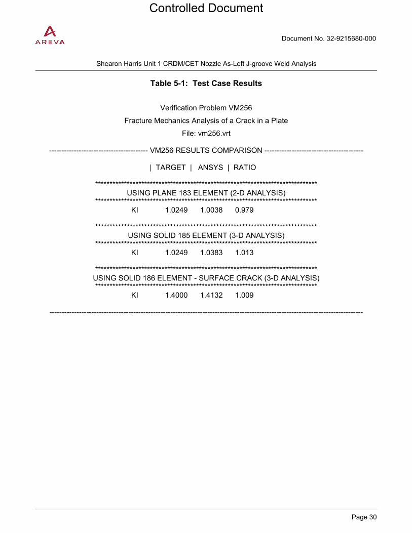
Document No. 32-9215680-000
PROPRIETARY
Shearon Harris Unit 1 CRDM/CET Nozzle As-Left J-groove Weld Analysis
Page 30
Table 5-1: Test Case Results
Verification Problem VM256
Fracture Mechanics Analysis of a Crack in a Plate
File: vm256.vrt
---------------------------------------- VM256 RESULTS COMPARISON ----------------------------------------
| TARGET | ANSYS | RATIO
***************************************************************************** USING PLANE 183 ELEMENT (2-D ANALYSIS)
***************************************************************************** KI 1.0249 1.0038 0.979
***************************************************************************** USING SOLID 185 ELEMENT (3-D ANALYSIS)
***************************************************************************** KI 1.0249 1.0383 1.013
***************************************************************************** USING SOLID 186 ELEMENT - SURFACE CRACK (3-D ANALYSIS) *****************************************************************************
KI 1.4000 1.4132 1.009
-------------------------------------------------------------------------------------------------------------------------------
Controlled Document

Document No. 32-9215680-000
PROPRIETARY
Shearon Harris Unit 1 CRDM/CET Nozzle As-Left J-groove Weld Analysis
Page 31
5.3 Computer Files
The computer files listed below are stored in the AREVA ColdStor repository in the directory “\cold\41304\32-9176350-000\official”.
ANSYS Models
File Name Description ColdStor Storage
Date
ColdStor Storage
Time Checksum
[ ] [
] 04-15-12 09:01:06 22856
[ ] [
] 04-15-12 09:00:56 18509
ANSYS Macros
File Name Description ColdStor Storage
Date
ColdStor Storage
Time Checksum
[ ] [ ] 04-15-12 09:01:22 15845
[ ] [ ] 04-15-12 09:01:21 11056
ANSYS Input Files
File Name Description ColdStor Storage
Date
ColdStor Storage
Time Checksum
[ ] [
] 04-15-12 09:01:42 32454
[ ] [
] 04-15-12 09:01:41 08793
Controlled Document
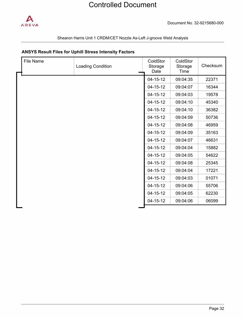
Document No. 32-9215680-000
PROPRIETARY
Shearon Harris Unit 1 CRDM/CET Nozzle As-Left J-groove Weld Analysis
Page 32
ANSYS Result Files for Uphill Stress Intensity Factors
File Name Loading Condition
ColdStor Storage
Date
ColdStor Storage
Time Checksum
04-15-12 09:04:35 22371
04-15-12 09:04:07 16344
04-15-12 09:04:03 19578
04-15-12 09:04:10 45340
04-15-12 09:04:10 36382
04-15-12 09:04:09 50736
04-15-12 09:04:08 46959
04-15-12 09:04:09 35163
04-15-12 09:04:07 46631
04-15-12 09:04:04 15882
04-15-12 09:04:05 54622
04-15-12 09:04:08 25345
04-15-12 09:04:04 17221
04-15-12 09:04:03 01071
04-15-12 09:04:06 55706
04-15-12 09:04:05 62230
04-15-12 09:04:06 06099
Controlled Document

Document No. 32-9215680-000
PROPRIETARY
Shearon Harris Unit 1 CRDM/CET Nozzle As-Left J-groove Weld Analysis
Page 33
ANSYS Result Files for Downhill Stress Intensity Factors
File Name Loading Condition ColdStor
Storage Date
ColdStor Storage
Time Checksum
04-15-12 09:04:34 59428
04-15-12 09:03:13 59492
04-15-12 09:03:10 49475
04-15-12 09:03:16 50217
04-15-12 09:03:17 37165
04-15-12 09:03:16 34304
04-15-12 09:03:15 19734
04-15-12 09:03:16 29947
04-15-12 09:03:14 23156
04-15-12 09:03:11 35585
04-15-12 09:03:12 60112
04-15-12 09:03:15 42106
04-15-12 09:03:11 65275
04-15-12 09:03:10 04872
04-15-12 09:03:13 36168
04-15-12 09:03:12 09825
04-15-12 09:03:13 31095
Controlled Document

Document No. 32-9215680-000
PROPRIETARY
Shearon Harris Unit 1 CRDM/CET Nozzle As-Left J-groove Weld Analysis
Page 34
Excel Spreadsheets
File Name Description ColdStor
Storage Date
ColdStor Storage
Time Checksum
04-15-12 09:06:58 58102
04-15-12 09:06:57 00505
04-15-12 09:06:57 38955
04-15-12 09:06:57 63694
04-15-12 09:06:56 21575
04-15-12 09:06:56 25218
ANSYS Test Cases
File Name Description ColdStor Storage
Date
ColdStor Storage
Time Checksum
[ ] [
] 04-15-12 09:07:25 49343
Controlled Document

Document No. 32-9215680-000
PROPRIETARY
Shearon Harris Unit 1 CRDM/CET Nozzle As-Left J-groove Weld Analysis
Page 35
6.0 CALCULATIONS
Propagation of a postulated initial flaw in the J-groove weld and butter is calculated to determine the final flaw size after 30 years of service. Flaw evaluations are then performed to assess the acceptability of the final flaw size.
6.1 Initial Flaw Size
It is both difficult and unnecessary to prescribe initial flaw sizes for the “non-classical” flaw shapes comprising the postulated uphill and downhill flaws in the J-groove weld and butter. Since the explicit finite element crack models described in Section 2.1.1 were developed to realistically capture the basic geometry of the J-shaped flaws, any characteristic dimension of the flaws may be used to track flaw growth during cyclic fatigue. The “constant depth” J-groove design suggests that a common value can be utilized to describe the initial depth of the uphill and downhill flaws. Accordingly, the vertical distance along the uphill side penetration bore, from the inside surface of the cladding to the weld-to-butter/head interface, is used to define the initial flaw size, ao (as shown Figure 2-1). From the uphill crack model, the initial flaw size value is determined to be 2.1482″.
As discussed in Section 2.1.3, crack tip stress intensity factors are calculated directly from the finite element crack models for the initial flaw size and then updated based on incremental crack growth according to
)a(K 1iI + = i
1iiI a
a)a(K + ,
so that after the first increment of crack growth,
)a(K iI = 0
10I a
a)a(K .
6.2 Fatigue Crack Growth
Although it is believed that a PWSCC flaw would be confined to the J-groove weld and butter, it is postulated that a fatigue flaw would initiate in the low alloy steel head, combine with the PWSCC flaw, and propagate farther into the head under cyclic loads. Fatigue crack growth is calculated from finite element based stress intensity factors using residual and operational stresses from References [3] and [12], respectively. The actual flaw growth calculations are presented in Appendix A for the uphill flaw and Appendix B for the downhill flaw, along with a comparison of the final stress intensity factor for each transient with the fracture toughness requirements of Section XI. Table 6-1 and Table 6-2 summarize the flaw growth analyses for the uphill and downhill sides of the flaw, respectively. These tables serve several purposes; they present the final flaw size at the end the design life, they compare stress intensity factors at the final flaw size with LEFM acceptance criteria, and they serve as a means of screening for the worst case loading conditions and stress intensity factors for subsequent EPFM analysis.
Crack growth is calculated in one-year increments for each of the analyzed transients, while uniformly distributing the growth over the service life by linking the yearly crack growth between the crack growth tables in Appendix A for the uphill flaw and the tables in Appendix B for the downhill flaw.
Controlled Document

Document No. 32-9215680-000
PROPRIETARY
Shearon Harris Unit 1 CRDM/CET Nozzle As-Left J-groove Weld Analysis
Page 36
Stress intensity factors are provided in the crack growth tables for all locations along the postulated crack fronts, including the cladding. It is apparent from the tables in Appendix A that on the uphill side of the penetration, the highest stress intensity factors in the low alloy steel head occur near the cladding surface (Position 3) for residual stresses and near the penetration bore (Position 16) for operating stresses. It is noted that due to residual tensile strain in the cladding material, cladding stresses and the associated stress intensity factors may be higher than those in the adjacent head material. However, stress intensity factors within the stainless steel cladding portion of the crack front need not be considered in the evaluation of the potential for non-ductile failure of the low alloy steel head. Fatigue crack growth analysis performed for both Position 3 and 16 showed that the operating stresses controlled, producing higher final stress intensity factors at Position 16. Thus Position 16 on the uphill side will be used to calculate fatigue crack growth and evaluate the final stress intensity factors for each transient considering flaw acceptance standards for the low alloy steel head material. The downhill side crack growth tables in Appendix B, use Position 7 to calculate crack growth and evaluate fracture toughness margins since the highest stress intensity factors occur either at or near this crack front position for both the residual and operating stresses.
Controlled Document

Document No. 32-9215680-000
PROPRIETARY
Shearon Harris Unit 1 CRDM/CET Nozzle As-Left J-groove Weld Analysis
Page 37
Table 6-1: LEFM Fracture Toughness Margins for Uphill Side
Period of Operation: Time = 30 years
Flaw Size: a =
Loading Conditions
Temperature
Pressure
Fracture Toughness, KIc 200.0 200.0 98.0 200.0 200.0 200.0 63.5 200.0 200.0 200.0 200.0 200.0 200.0 63.5 200.0 ksi√in
Fracture Toughness, KIa 200.0 85.5 55.2 200.0 200.0 200.0 43.2 200.0 200.0 200.0 200.0 200.0 200.0 43.2 200.0 ksi√in
Position 16
KI(a) 73.546 50.736 31.531 78.325 79.225 94.843 64.199 82.085 72.962 109.077 73.540 96.413 89.569 233.116 190.113 ksi√in
ae 3.1971 3.0955 3.0602 3.2163 3.2219 3.2883 3.1266 3.2381 3.1944 3.3708 3.1972 3.2988 3.2369 4.1923 3.9097 in.
KI(ae) 75.434 51.204 31.640 80.576 81.573 98.653 65.117 84.729 74.802 114.874 75.428 100.448 92.437 273.795 215.630 ksi√in
Margin = KIc / KI(ae) n/a n/a n/a n/a n/a n/a n/a n/a n/a n/a n/a n/a n/a 0.23 0.93
Margin = KIa / KI(ae) 2.65 1.67 1.75 2.48 2.45 2.03 0.66 2.36 2.67 1.74 2.65 1.99 2.16 n/a n/a
Required Margin 3.16 1.41 1.41 3.16 3.16 3.16 1.41 3.16 3.16 3.16 3.16 3.16 3.16 1.41 1.41
Acceptable by LEFM? No Yes Yes No No No No No No No No No No No No
where: ae = a + 1/(6π) [KI(a)/Sy]2
KI(ae) = KI(a)*√(ae/a)
Controlled Document

Document No. 32-9215680-000
PROPRIETARY
Shearon Harris Unit 1 CRDM/CET Nozzle As-Left J-groove Weld Analysis
Page 38
Table 6-2: LEFM Fracture Toughness Margins for Downhill Side
Period of Operation: Time = 30 years
Flaw Size: a =
Loading Conditions
Temperature
Pressure
Fracture Toughness, KIc 200.0 200.0 98.0 200.0 200.0 200.0 63.5 200.0 200.0 200.0 200.0 200.0 200.0 63.5 200.0 ksi√in
Fracture Toughness, KIa 200.0 85.5 55.2 200.0 200.0 200.0 43.2 200.0 200.0 200.0 200.0 200.0 200.0 43.2 200.0 ksi√in
Position 7
KI(a) 56.220 22.499 17.076 58.314 58.716 65.540 55.130 59.913 55.969 72.039 56.216 66.756 65.585 77.409 63.626 ksi√in
ae 2.3201 2.2388 2.2339 2.3259 2.3279 2.3467 2.2923 2.3337 2.3191 2.3724 2.3201 2.3515 2.3338 2.3549 2.3255 in.
KI(ae) 57.373 22.555 17.099 59.585 60.021 67.267 55.923 61.322 57.105 74.341 57.369 68.584 67.127 79.587 65.007 ksi√in
Margin = KIc / KI(ae) n/a n/a n/a n/a n/a n/a n/a n/a n/a n/a n/a n/a n/a 0.80 3.08
Margin = KIa / KI(ae) 3.49 3.79 3.23 3.36 3.33 2.97 0.77 3.26 3.50 2.69 3.49 2.92 2.98 n/a n/a
Required Margin 3.16 1.41 1.41 3.16 3.16 3.16 1.41 3.16 3.16 3.16 3.16 3.16 3.16 1.41 1.41
Acceptable by LEFM? Yes Yes Yes Yes Yes No No Yes Yes No Yes No No No Yes
where: ae = a + 1/(6π) [KI(a)/Sy]2
KI(ae) = KI(a)*√(ae/a)
Controlled Document

Document No. 32-9215680-000
PROPRIETARY
Shearon Harris Unit 1 CRDM/CET Nozzle As-Left J-groove Weld Analysis (NonProprietary)
Page 39
6.3 LEFM Flaw Evaluations
Results of the linear-elastic fracture mechanics flaw evaluations are summarized below for the final flaw size after 30 years of crack growth.
6.3.1 Normal and Upset Conditions
Listed below are the controlling LEFM fracture toughness margins from the fatigue crack growth tables.
Uphill Side Downhill Side Flaw Sizes Initial flaw size, ai = 2.148 in. 2.148 in.
Final flaw size, af = [ ] in. [ ] in.
Flaw growth, Δa = [ ] in. [ ] in. Operating Conditions Reactor Trip Reactor Trip
Temperature, T = [ ] oF [ ] oF
Fracture toughness, KIa = 200.0 ksi√in 200.0 ksi√in
Final stress intensity factor, KI(af) = 109.1 ksi√in 72.04 ksi√in
Effective flaw size, ae = 3.371 in. 2.372 in.
Effective stress intensity factor, KI(ae) = 114.9 ksi√in 74.34 ksi√in
Fracture toughness margin (> 3.16), KIa/KI(ae) = 1.74 2.69 Low Temperature Conditions Refueling Refueling
Temperature, T = [ ] oF [ ] oF
Fracture toughness, KIa = 43.2 ksi√in 43.2 ksi√in
Final stress intensity factor, KI(af) = 64.20 ksi√in 55.13 ksi√in
Effective flaw size, ae = 3.127 in. 2.292 in.
Effective stress intensity factor, KI(ae) = 65.12 ksi√in 55.92 ksi√in
Fracture toughness margin (> 1.41), KIa/KI(ae) = 0.66 0.77
Since the above fracture toughness margins for the controlling normal and upset conditions are less than the Code required minimums, EPFM flaw evaluations will be performed in Section 6.4 to account for the ductile behavior of the low alloy steel under stable crack propagation.
Controlled Document

Document No. 32-9215680-000
PROPRIETARY
Shearon Harris Unit 1 CRDM/CET Nozzle As-Left J-groove Weld Analysis (NonProprietary)
Page 40
6.3.2 Faulted Conditions
The bounding faulted condition stress intensity factors are evaluated below for the final flaw size after 30 years of crack growth.
Uphill Side Downhill Side Flaw Sizes
Final flaw size, af = [ ] in. [ ] in. Large Loss of Coolant Accident
Temperature, T = [ ] oF [ ] oF
Fracture toughness, KIc = 63.5 ksi√in 63.5 ksi√in
Final stress intensity factor, KI(af) = 233.1 ksi√in 77.41 ksi√in
Effective flaw size, ae = 4.192 in. 2.355 in.
Effective stress intensity factor, KI(ae) = 273.8 ksi√in 79.59 ksi√in
Fracture toughness margin (> 1.41), KIc/KI(ae) = 0.23 0.80 Large Steam Line Break
Temperature, T = [ ] oF [ ] oF
Fracture toughness, KIc = 200.0 ksi√in 200.0 ksi√in
Final stress intensity factor, KI(af) = 190.1 ksi√in 63.63 ksi√in
Effective flaw size, ae = 3.910 in. 2.326 in.
Effective stress intensity factor, KI(ae) = 215.6 ksi√in 65.01 ksi√in
Fracture toughness margin (> 1.41), KIc/KI(ae) = 0.93 3.08
Since some of the above fracture toughness margins for the controlling faulted conditions are less than the Code required minimums, EPFM flaw evaluations will be performed in Section 6.4 to account for the ductile behavior of the low alloy steel under stable crack propagation.
Controlled Document

Document No. 32-9215680-000
PROPRIETARY
Shearon Harris Unit 1 CRDM/CET Nozzle As-Left J-groove Weld Analysis (NonProprietary)
Page 41
6.4 EPFM Flaw Evaluations
The EPFM analysis is used to evaluate the limiting loading conditions that fail the LEFM-based Code margins. In this context, EPFM is meant to include either classical elastic-plastic fracture mechanics or limit load analysis, as applicable.
6.4.1 Operating Conditions
Uphill Side Downhill Side
Controlling Conditions Reactor Trip Reactor Trip
Flaw size at 30 years of service, a = [ ] in. [ ] in.
Effective flaw size, ae = 3.371 in. 2.373 in.
SCREENING PROCEDURE
T = [ ] oF [ ] oF
E = 27200 ksi 27200 ksi
ν = 0.3 0.3
E’ = E/(1-ν2) = 29890 ksi 29890 ksi
σy = 43.6 ksi 43.6 ksi
σu = 80.0 ksi 80.0 ksi
σf = 61.8 ksi 61.8 ksi
Crack initiation toughness, KIc = 200.0 ksi√in 200.0 ksi√in
Total applied KI, KI(ae) = 114.9 ksi√in 74.34 ksi√in
Kr’ = KI(ae) / KIc = 0.574 0.372 From finite element analysis, the maximum crack face stresses due to residual stress, pressure, and thermal gradients are σmax = 68.3 ksi 70.9 ksi
Sr’ = σmax / σf = 1.105 1.147
Screening ratio, Kr’ / Sr’ = 0.520 0.324
(1.8 > Kr’ / Sr’ ≥ 0.2) (1.8 > Kr’ / Sr’ ≥ 0.2)
Analysis regime: EPFM EPFM
Controlled Document

Document No. 32-9215680-000
PROPRIETARY
Shearon Harris Unit 1 CRDM/CET Nozzle As-Left J-groove Weld Analysis (NonProprietary)
Page 42
EPFM ANALYSIS Uphill Side Downhill Side
Controlling Conditions Reactor Trip Reactor Trip KI primary, KIp(a) = 190.8 ksi√in 86.02 ksi√in
KI secondary (residual plus thermal), KIs(a) = 68.19 ksi√in 65.05 ksi√in
Total KI, KI(a) = 259.0 ksi√in 151.1 ksi√in
Effective flaw size, ae = 4.912 in. 2.865 in.
Total KI, KI’(ae) = 329.3 ksi√in 171.3 ksi√in
Table A-14 (uphill side) and Table B-14 (downhill side) develop all the data necessary to construct J-T diagrams for the controlling operating conditions. The J-T diagrams are presented in Figures A-1 and B-1 for the uphill and downhill sides, respectively.
Uphill Side:
It can be seen from Table A-14 that for an applied J-integral of 3.628 kips/in, corresponding to safety factors of 3 and 1.5, the applied tearing modulus, 8.502, is less than the material tearing modulus, 50.70, indicating flaw stability. Alternately, the applied J-integral is less than the J-integral, 8.181 kips/in, at the point of instability. For safety factors of 1.5 and 1, the applied J-integral of 0.785 kips/in is less than the J0.1 value of 2.473 kips/in, demonstrating that the crack driving force falls below the J-R curve at a crack extension of 0.1 inch.
Downhill Side:
Table B-14 shows that for an applied J-integral of 0.982 kips/in, corresponding to safety factors of 3 and 1.5, the applied tearing modulus, 3.139, is less than the material tearing modulus, 242.0, indicating flaw stability. The applied J-integral is also less than the J-integral, 7.102 kips/in, at the point of instability. For safety factors of 1.5 and 1, the applied J-integral of 0.273 kips/in is less than the J0.1 value of 2.473 kips/in, demonstrating that the crack driving force falls below the J-R curve at a crack extension of 0.1 inch.
Controlled Document

Document No. 32-9215680-000
PROPRIETARY
Shearon Harris Unit 1 CRDM/CET Nozzle As-Left J-groove Weld Analysis (NonProprietary)
Page 43
6.4.2 Low Temperature Conditions
Uphill Side Downhill Side
Controlling Conditions Refueling Refueling
Flaw size at 30 years of service, a = [ ] in. [ ] in.
Effective flaw size, ae = 3.127 in. 2.292 in.
SCREENING PROCEDURE
T = [ ] oF [ ] oF
E = 29200 ksi 29200 ksi
ν = 0.3 0.3
E’ = E/(1-ν2) = 32080 ksi 32080 ksi
σy = 50.0 ksi 50.0 ksi
σu = 80.0 ksi 80.0 ksi
σf = 65.0 ksi 65.0 ksi
Crack initiation toughness, KIc = 63.5 ksi√in 63.5 ksi√in
Total applied KI, KI(ae) = 65.12 ksi√in 55.92 ksi√in
Kr’ = KI(ae) / KIc = 1.025 0.880 From finite element analysis, the maximum crack face stresses due to residual stress, pressure, and thermal gradients are σmax = 59.1 ksi 49.5 ksi
Sr’ = σmax / σf = 0.909 0.762
Screening ratio, Kr’ / Sr’ = 1.127 1.156
(1.8 > Kr’ / Sr’ ≥ 0.2) (1.8 > Kr’ / Sr’ ≥ 0.2)
Analysis regime: EPFM EPFM
Controlled Document

Document No. 32-9215680-000
PROPRIETARY
Shearon Harris Unit 1 CRDM/CET Nozzle As-Left J-groove Weld Analysis (NonProprietary)
Page 44
EPFM ANALYSIS Uphill Side Downhill Side
Controlling Conditions Refueling Refueling KI primary, KIp(a) = 0.0 ksi√in 0.0 ksi√in
KI secondary (residual plus thermal), KIs(a) = 96.30 ksi√in 82.70 ksi√in
Total KI, KI(a) = 96.30 ksi√in 82.70 ksi√in
Effective flaw size, ae = 3.236 in. 2.373 in.
Total KI, KI’(ae) = 99.37 ksi√in 85.35 ksi√in
Table A-15 (uphill side) and Table B-15 (downhill side) develop all the data necessary to construct J-T diagrams for the controlling operating conditions. The J-T diagrams are presented in Figures A-2 and B-2 for the uphill and downhill sides, respectively.
Uphill Side:
It can be seen from Table A-15 that for an applied J-integral of 0.308 kips/in, corresponding to safety factors of 3 and 1.5, the applied tearing modulus, 0.700, is less than the material tearing modulus, 942.9, indicating flaw stability. Alternately, the applied J-integral is less than the J-integral, 8.179 kips/in, at the point of instability. For safety factors of 1.5 and 1, the applied J-integral of 0.132 kips/in is less than the J0.1 value of 2.474 kips/in, demonstrating that the crack driving force falls below the J-R curve at a crack extension of 0.1 inch.
Downhill Side:
Table B-15 shows that for an applied J-integral of 0.227 kips/in, corresponding to safety factors of 3 and 1.5, the applied tearing modulus, 0.704, is less than the material tearing modulus, 1357, indicating flaw stability. The applied J-integral is also less than the J-integral, 7.101 kips/in, at the point of instability. For safety factors of 1.5 and 1, the applied J-integral of 0.097 kips/in is less than the J0.1 value of 2.474 kips/in, demonstrating that the crack driving force falls below the J-R curve at a crack extension of 0.1 inch.
Controlled Document

Document No. 32-9215680-000
PROPRIETARY
Shearon Harris Unit 1 CRDM/CET Nozzle As-Left J-groove Weld Analysis (NonProprietary)
Page 45
6.4.3 Faulted Conditions
Uphill Side Downhill Side
Controlling Conditions LLOCA LLOCA
Flaw size at 30 years of service, a = [ ] in. [ ] in.
Effective flaw size, ae = 4.192 in. 2.355 in.
SCREENING PROCEDURE
T = [ ] oF [ ] oF
E = 29200 ksi 29200 ksi
ν = 0.3 0.3
E’ = E/(1-ν2) = 32080 ksi 32080 ksi
σy = 50.0 ksi 50.0 ksi
σu = 80.0 ksi 80.0 ksi
σf = 65.0 ksi 65.0 ksi
Crack initiation toughness, KIc = 63.5 ksi√in 63.5 ksi√in
Total applied KI, KI(ae) = 273.8 ksi√in 79.59 ksi√in
Kr’ = KI(ae) / KIc = 4.310 1.253 From finite element analysis, the maximum crack face stresses due to residual stress, pressure, and thermal gradients are σmax = 198.3 ksi 163.2 ksi
Sr’ = σmax / σf = 3.051 2.511
Screening ratio, Kr’ / Sr’ = 1.413 0.499
(1.8 > Kr’ / Sr’ ≥ 0.2) (1.8 > Kr’ / Sr’ ≥ 0.2)
Analysis regime: EPFM EPFM
Controlled Document

Document No. 32-9215680-000
PROPRIETARY
Shearon Harris Unit 1 CRDM/CET Nozzle As-Left J-groove Weld Analysis (NonProprietary)
Page 46
EPFM ANALYSIS Uphill Side Downhill Side
Controlling Conditions LLOCA LLOCA KI primary, KIp(a) = 2.596 ksi√in 1.170 ksi√in
KI secondary (residual plus thermal), KIs(a) = 231.4 ksi√in 76.63 ksi√in
Total KI, KI(a) = 234.0 ksi√in 77.80 ksi√in
Effective flaw size, ae = 4.201 in. 2.356 in.
Total KI, KI’(ae) = 275.1 ksi√in 80.01 ksi√in
Table A-16 (uphill side) and Table B-16 (downhill side) develop all the data necessary to construct J-T diagrams for the controlling operating conditions. The J-T diagrams are presented in Figures A-3 and B-3 for the uphill and downhill sides, respectively.
Uphill Side:
It can be seen from Table A-16 that for an applied J-integral of 2.359 kips/in, corresponding to safety factors of 1.5 and 1, the applied tearing modulus, 5.364, is less than the material tearing modulus, 82.38, indicating flaw stability. Alternately, the applied J-integral is less than the J-integral, 8.179 kips/in, at the point of instability. For safety factors of 1.5 and 1, the applied J-integral of 2.359 kips/in is less than the J0.1 value of 2.474 kips/in, demonstrating that the crack driving force falls below the J-R curve at a crack extension of 0.1 inch.
Downhill Side:
Table B-16 shows that for an applied J-integral of 0.200 kips/in, corresponding to safety factors of 1.5 and 1, the applied tearing modulus, 0.619, is less than the material tearing modulus, 1584, indicating flaw stability. The applied J-integral is also less than the J-integral, 7.101 kips/in, at the point of instability. For safety factors of 1.5 and 1, the applied J-integral of 0.200 kips/in is less than the J0.1 value of 2.474 kips/in, demonstrating that the crack driving force falls below the J-R curve at a crack extension of 0.1 inch.
Controlled Document

Document No. 32-9215680-000
PROPRIETARY
Shearon Harris Unit 1 CRDM/CET Nozzle As-Left J-groove Weld Analysis (NonProprietary)
Page 47
6.5 Limit Load Analysis
A conservative limit load analysis is performed by comparing the remaining available head thickness to the minimum required thickness, tmin, from Section 2.3.2. This analysis is dependent only on the final flaw depth and is applicable to all loading conditions.
The spherical radius to the inside surface of the cladding is [ ] inches [1] and the spherical
radius to the initial flaw depth, obtained from the uphill crack model, is [ ] inches. The
maximum flaw growth, calculated on the uphill side and measured along the vertical bore, is [ ] inch, can also be used as a conservative measure of the flaw growth along a spherical radius. The final flaw depth, dr, measured along a spherical radius through the J-shaped flaw, is
rd = [ ]
The remaining head thickness, trem, is
remt = rbaseclad dtt −+
where cladt = [ ] in.
baset = [ ] in.
Then remt = 3.82 in. > mint = 3.74 in.
Since the remaining thickness is greater than the minimum required thickness, the conservative limit load evaluation criterion is satisfied.
Controlled Document

Document No. 32-9215680-000
PROPRIETARY
Shearon Harris Unit 1 CRDM/CET Nozzle As-Left J-groove Weld Analysis (NonProprietary)
Page 48
7.0 SUMMARY OF RESULTS AND CONCLUSIONS
Linear-elastic and elastic-plastic fracture mechanics has been used to evaluate a postulated radial flaw in the J-groove weld and butter of an outermost CRDM nozzle reactor vessel head penetration. It was determined that an acceptable flaw size would be present after 30 years of fatigue crack growth, as summarized below.
7.1 Summary of Results
Uphill Side Downhill Side Flaw Sizes Initial flaw size, ai = 2.148 in. 2.148 in.
Final flaw size after 30 years, af = [ ] in. [ ] in.
Flaw growth, Δa = [ ] in. [ ] in.
Operating Conditions Reactor Trip Reactor Trip
Temperature, T = [ ] oF [ ] oF
Material tearing modulus, Tmat = 50.70 242.0
Material J-integral at 0.1” crack extension, J0.1 = 2.473 kips/in. 2.473 kips/in.
Safety factors (primary/secondary), SF = 3 / 1.5 3 / 1.5
Applied tearing modulus (< Tmat) Tapp = 8.502 3.139
Safety factors (primary/secondary), SF = 1.5 / 1 1.5 / 1
Applied J-integral (< J0.1) Japp = 0.785 kips/in 0.273 kips/in
Low Temperature Conditions Refueling Refueling
Temperature, T = [ ] oF [ ] oF
Material tearing modulus, Tmat = 942.9 1357
Material J-integral at 0.1” crack extension, J0.1 = 2.474 kips/in. 2.474 kips/in.
Safety factors (primary/secondary), SF = 3 / 1.5 3 / 1.5
Applied tearing modulus (< Tmat) Tapp = 0.700 0.704
Safety factors (primary/secondary), SF = 1.5 / 1 1.5 / 1
Applied J-integral (< J0.1) Japp = 0.132 kips/in 0.097 kips/in
Controlled Document

Document No. 32-9215680-000
PROPRIETARY
Shearon Harris Unit 1 CRDM/CET Nozzle As-Left J-groove Weld Analysis (NonProprietary)
Page 49
Summary of Results (Cont’d) Faulted Conditions LLOCA LLOCA
Temperature, T = [ ] oF [ ] oF
Material tearing modulus, Tmat = 82.38 1584
Material J-integral at 0.1” crack extension, J0.1 = 2.474 kips/in. 2.474 kips/in.
Safety factors (primary/secondary), SF = 1.5 / 1 1.5 / 1
Applied tearing modulus (< Tmat) Tapp = 5.364 0.619
Safety factors (primary/secondary), SF = 1.5 / 1 1.5 / 1
Applied J-integral (< J0.1) Japp = 2.359 kips/in 0.200 kips/in
7.2 Conclusion
Based on a combination of linear elastic and elastic-plastic fracture mechanics analysis of a postulated remaining flaw in the original Alloy 182 J-groove weld and butter material, the Shearon Harris Unit 1 CRDM and CET nozzles are considered to be acceptable for at least 30 years of operation following an IDTB weld repair.
8.0 REFERENCES
1. AREVA Drawing 02-9175500E-005, “Shearon Harris CRDM ID Temper Bead Weld Repair”
2. AREVA Document 08-9172870-002, “Shearon Harris RVCH CRDM and CET Nozzle Penetration Modification”
3. AREVA Document 32-9176344-000, “Shearon Harris Unit 1 IDTB CRDM/CET Nozzle Weld Residual Stress Analysis” - Proprietary Document
4. AREVA Document 51-5012047-00, “Stress Corrosion Cracking of Low Alloy Steel”
5. ANSYS Finite Element Computer Code, Version 12.1, ANSYS Inc., Canonsburg, PA.
6. T.L. Anderson, Fracture Mechanics: Fundamentals and Applications, CRC Press, 1991.
7. ASME Boiler and Pressure Vessel Code, Section III, Rules for Construction of Nuclear Facility Components, Division 1, Subsection NB, Class 1 Components, 2001 Edition with Addenda through 2003.
8. ASME Boiler and Pressure Vessel Code, Section II, Materials, 2001 Edition with Addenda through 2003.
9. AREVA Document 38-2200979-000, “Shearon Harris - Proprietary Document Transmittal 1”
10. AREVA Document 55-PQ7183-005, “Procedure Qualification Record PQ7183-005”
Controlled Document

Document No. 32-9215680-000
PROPRIETARY
Shearon Harris Unit 1 CRDM/CET Nozzle As-Left J-groove Weld Analysis (NonProprietary)
Page 50
11. ASME Boiler and Pressure Vessel Code, Section XI, Rules for Inservice Inspection of Nuclear
Power Plant Components, 2001 Edition with Addenda through 2003.
12. AREVA Document 32-9175220-003, “Shearon Harris Unit 1 Contingency CRDM IDTB Weld Repair Analysis”
13. AREVA Document 38-2201004-000, “Shearon Harris - Proprietary Document Transmittal 4”
Controlled Document

Document No. 32-9215680-000
PROPRIETARY
Shearon Harris Unit 1 CRDM/CET Nozzle As-Left J-groove Weld Analysis (NonProprietary)
Page 51
APPENDIX A: DETAILED FLAW EVALUATIONS FOR UPHILL SIDE
This appendix presents the fatigue crack growth tables and the elastic-plastic fracture mechanics flaw evaluations for the uphill side of the CRDM penetration.
Table A-1: Stress Intensification Factors for Uphill Side – Welding Residual Stress
Condition WRSTemperature 70.0 F
Pressure n/a psigSy 50.0 ksiKIc 98.0 ksi√inKIa 55.2 ksi√in
Crack Front KI
Position (ksi√in)1 45.1182 41.0563 38.4354 31.1915 27.7476 24.3657 20.5138 14.7739 18.05510 9.77211 -2.10112 7.35213 14.34414 18.76315 22.13316 26.50917 17.849
Controlled Document

Document No. 32-9215680-000
PROPRIETARY
Shearon Harris Unit 1 CRDM/CET Nozzle As-Left J-groove Weld Analysis (NonProprietary)
Page 52
Table A-2: Fatigue Crack Growth for Uphill Side – Heatup/Cooldown
STRESS INTENSITY FACTORS FATIGUE CRACK GROWTH
Condition* HU1 HU2 CD SD Transient Description: 200 cycles over 40 yearsTemperature 557.0 349.0 120.0 70.0 F
Pressure 2317 467 467 0 psig ΔN = 5.0 cycles/yearSy 42.6 44.9 49.2 50.0 ksiKIc 200.0 200.0 200.0 98.0 ksi√in Position 16KIa 200.0 200.0 85.5 55.2 ksi√in Operating HU1 HU2 CD SD
Crack Front Time Cycle a KI(a) KI(a) ΔKI Δa KI(a) KI(a)
Position (ksi√in) (ksi√in) (ksi√in) (ksi√in) (end of yr.) (in.) (ksi√in) (ksi√in) (ksi√in) (in.) (ksi√in) (ksi√in)1 18.527 -18.920 13.250 0.000 0 0.0 61.833 13.247 48.586 42.656 26.5092 18.826 -17.438 12.738 0.000 1 5.0 61.857 13.252 48.604 42.672 26.5193 19.351 -15.934 12.257 0.000 2 10.0 62.217 13.329 48.888 42.921 26.6744 18.420 -13.078 10.820 0.000 3 15.0 62.579 13.407 49.172 43.171 26.8295 18.505 -11.272 10.097 0.000 4 20.0 62.943 13.485 49.458 43.422 26.9856 18.197 -9.462 9.289 0.000 5 25.0 63.309 13.563 49.746 43.674 27.1427 16.954 -7.589 8.195 0.000 6 30.0 63.678 13.642 50.035 43.929 27.3008 12.946 -5.678 6.169 0.000 7 35.0 64.048 13.722 50.326 44.184 27.4599 16.968 -5.646 7.508 0.000 8 40.0 64.420 13.801 50.619 44.441 27.61810 8.787 -3.529 4.085 0.000 9 45.0 64.795 13.881 50.913 44.699 27.77911 -3.688 -1.066 -0.898 0.000 10 50.0 65.171 13.962 51.209 44.959 27.94012 7.147 -2.712 3.264 0.000 11 55.0 65.550 14.043 51.506 45.220 28.10213 14.991 -4.996 6.623 0.000 12 60.0 65.930 14.125 51.805 45.483 28.26614 20.357 -7.186 9.121 0.000 13 65.0 66.313 14.207 52.106 45.747 28.43015 25.782 -9.743 11.777 0.000 14 70.0 66.698 14.289 52.409 46.012 28.59516 35.324 -13.262 16.147 0.000 15 75.0 67.085 14.372 52.713 46.279 28.76117 23.491 -9.495 10.995 0.000 16 80.0 67.474 14.455 53.018 46.547 28.927
17 85.0 67.865 14.539 53.326 46.817 29.095* Condition Description 18 90.0 68.258 14.624 53.635 47.089 29.264
HU1 Time step 6 at 7.67 hr. (Heatup) - Maximum KI 19 95.0 68.654 14.708 53.946 47.362 29.433HU2 Time step 3 at 2.29 hr. (Heatup) - Minimum KI 20 100.0 69.052 14.794 54.258 47.636 29.604CD Time step 15 at 14.37 hr. - Maximum KI at Low Temperature 21 105.0 69.452 14.879 54.572 47.912 29.775SD Shutdown at Ambient Conditions 22 110.0 69.854 14.965 54.888 48.189 29.948
23 115.0 70.258 15.052 55.206 48.468 30.12124 120.0 70.665 15.139 55.526 48.749 30.29525 125.0 71.073 15.227 55.847 49.031 30.47126 130.0 71.484 15.315 56.170 49.314 30.64727 135.0 71.898 15.403 56.494 49.599 30.82428 140.0 72.313 15.492 56.821 49.886 31.00229 145.0 72.731 15.582 57.149 50.174 31.18130 150.0 73.151 15.672 57.479 50.464 31.361
Stress Intensity Factor, KI
Controlled Document

Document No. 32-9215680-000
PROPRIETARY
Shearon Harris Unit 1 CRDM/CET Nozzle As-Left J-groove Weld Analysis (NonProprietary)
Page 53
Table A-3: Fatigue Crack Growth for Uphill Side – Unit Loading/Unloading
STRESS INTENSITY FACTORS FATIGUE CRACK GROWTH
Condition* UL UU Transient Description: 18300 cycles over 40 yearsTemperature 533.8 574.3 F
Pressure 2265 2209 psig ΔN = 457.5 cycles/yearSy 42.9 42.4 ksiKIc 200.0 200.0 ksi√inKIa 200.0 200.0 ksi√in Operating UL UU
Crack Front Time Cycle a KI(a) KI(a) ΔKI Δa
Position (ksi√in) (ksi√in) (end of yr.) (in.) (ksi√in) (ksi√in) (ksi√in) (in.)1 23.007 10.659 0 0.0 65.851 53.629 12.2222 23.018 11.371 1 457.5 65.891 53.662 12.2293 23.249 12.295 2 915.0 66.275 53.974 12.3014 21.710 12.334 3 1372.5 66.661 54.288 12.3725 21.430 12.954 4 1830.0 67.049 54.604 12.4446 20.760 13.214 5 2287.5 67.439 54.922 12.5177 19.115 12.658 6 2745.0 67.831 55.241 12.5898 14.550 9.722 7 3202.5 68.225 55.563 12.6639 18.795 13.197 8 3660.0 68.622 55.886 12.73610 9.829 6.679 9 4117.5 69.021 56.210 12.81011 -3.731 -3.452 10 4575.0 69.422 56.537 12.88512 7.964 5.477 11 5032.5 69.825 56.865 12.96013 16.596 11.668 12 5490.0 70.230 57.196 13.03514 22.593 15.748 13 5947.5 70.638 57.528 13.11015 28.716 19.782 14 6405.0 71.048 57.861 13.18716 39.342 27.120 15 6862.5 71.460 58.197 13.26317 26.287 17.846 16 7320.0 71.875 58.535 13.340
17 7777.5 72.291 58.874 13.417* Condition Description 18 8235.0 72.710 59.215 13.495
UL Time step 12 at 0.29 hr. - Maximum KI 19 8692.5 73.132 59.559 13.573UU Time step 11 at 0.29 hr. - Minimum KI 20 9150.0 73.555 59.904 13.652
21 9607.5 73.981 60.250 13.73122 10065.0 74.410 60.599 13.81123 10522.5 74.841 60.950 13.89024 10980.0 75.274 61.303 13.97125 11437.5 75.709 61.657 14.05226 11895.0 76.147 62.014 14.13327 12352.5 76.587 62.372 14.21528 12810.0 77.030 62.733 14.29729 13267.5 77.475 63.095 14.37930 13725.0 77.922 63.460 14.462
KI
Position 16
Controlled Document

Document No. 32-9215680-000
PROPRIETARY
Shearon Harris Unit 1 CRDM/CET Nozzle As-Left J-groove Weld Analysis (NonProprietary)
Page 54
Table A-4: Fatigue Crack Growth for Uphill Side – Step Load Increase/Decrease
STRESS INTENSITY FACTORS FATIGUE CRACK GROWTH
Condition* SLI SLD Transient Description: 4000 cycles over 40 yearsTemperature 551.4 570.8 F
Pressure 2367 2246 psig ΔN = 100.0 cycles/yearSy 42.7 42.5 ksiKIc 200.0 200.0 ksi√inKIa 200.0 200.0 ksi√in Operating SLI SLD
Crack Front Time Cycle a KI(a) KI(a) ΔKI Δa
Position (ksi√in) (ksi√in) (end of yr.) (in.) (ksi√in) (ksi√in) (ksi√in) (in.)1 22.974 11.043 0 0.0 66.608 54.168 12.4402 23.070 11.733 1 100.0 66.884 54.393 12.4923 23.434 12.620 2 200.0 67.274 54.709 12.5644 21.981 12.614 3 300.0 67.665 55.028 12.6375 21.803 13.209 4 400.0 68.059 55.348 12.7116 21.191 13.451 5 500.0 68.455 55.670 12.7857 19.546 12.878 6 600.0 68.853 55.994 12.8598 14.887 9.896 7 700.0 69.253 56.319 12.9349 19.268 13.414 8 800.0 69.656 56.647 13.00910 10.061 6.796 9 900.0 70.061 56.976 13.08511 -3.874 -3.486 10 1000.0 70.468 57.307 13.16112 8.146 5.579 11 1100.0 70.877 57.640 13.23713 16.990 11.874 12 1200.0 71.288 57.974 13.31414 23.108 16.034 13 1300.0 71.702 58.311 13.39115 29.318 20.161 14 1400.0 72.118 58.649 13.46916 40.099 27.659 15 1500.0 72.536 58.989 13.54717 26.771 18.203 16 1600.0 72.957 59.331 13.626
17 1700.0 73.380 59.675 13.705* Condition Description 18 1800.0 73.805 60.021 13.784
SLI Time step 10 at 0.05 hr. - Maximum KI 19 1900.0 74.233 60.369 13.864SLD Time step 10 at 0.042 hr. - Minimum KI 20 2000.0 74.663 60.718 13.944
21 2100.0 75.095 61.070 14.02522 2200.0 75.530 61.424 14.10623 2300.0 75.967 61.779 14.18824 2400.0 76.406 62.136 14.27025 2500.0 76.848 62.496 14.35326 2600.0 77.293 62.857 14.43627 2700.0 77.739 63.221 14.51928 2800.0 78.189 63.586 14.60329 2900.0 78.640 63.953 14.68730 3000.0 79.095 64.323 14.772
Position 16
KI
Controlled Document

Document No. 32-9215680-000
PROPRIETARY
Shearon Harris Unit 1 CRDM/CET Nozzle As-Left J-groove Weld Analysis (NonProprietary)
Page 55
Table A-5: Fatigue Crack Growth for Uphill Side – Turbine Roll Test STRESS INTENSITY FACTORS FATIGUE CRACK GROWTH
Condition* TRT1 TRT2 Transient Description: 80 cycles over 40 yearsTemperature 443.4 557.4 F
Pressure 1692 2317 psig ΔN = 2.0 cycles/yearSy 43.8 42.6 ksiKIc 200.0 200.0 ksi√inKIa 200.0 200.0 ksi√in Operating TRT1 TRT2
Crack Front Time Cycle a KI(a) KI(a) ΔKI Δa
Position (ksi√in) (ksi√in) (end of yr.) (in.) (ksi√in) (ksi√in) (ksi√in) (in.)1 40.587 7.354 0 0.0 79.738 50.447 29.2912 39.304 8.260 1 2.0 80.133 50.697 29.4363 38.158 9.378 2 4.0 80.599 50.992 29.6074 34.061 9.845 3 6.0 81.069 51.289 29.7805 32.161 10.713 4 8.0 81.540 51.587 29.9536 29.935 11.230 5 10.0 82.015 51.887 30.1277 26.687 10.973 6 12.0 82.492 52.189 30.3038 20.115 8.468 7 14.0 82.971 52.493 30.4799 24.921 11.756 8 16.0 83.453 52.798 30.65610 13.413 5.859 9 18.0 83.938 53.104 30.83411 -3.551 -3.409 10 20.0 84.426 53.413 31.01312 10.752 4.835 11 22.0 84.916 53.723 31.19313 21.987 10.400 12 24.0 85.409 54.035 31.37414 30.173 13.981 13 26.0 85.905 54.348 31.55615 38.799 17.463 14 28.0 86.403 54.664 31.73916 53.229 23.938 15 30.0 86.904 54.981 31.92317 36.060 15.642 16 32.0 87.408 55.300 32.109
17 34.0 87.915 55.620 32.295* Condition Description 18 36.0 88.424 55.943 32.482
TRT1 Time step 5 at 0.278 hr. - Maximum KI 19 38.0 88.937 56.267 32.670TRT2 Time step 8 at 1.418 hr. - Minimum KI 20 40.0 89.452 56.593 32.859
21 42.0 89.970 56.920 33.05022 44.0 90.491 57.250 33.24123 46.0 91.014 57.581 33.43324 48.0 91.541 57.914 33.62725 50.0 92.070 58.249 33.82126 52.0 92.603 58.586 34.01727 54.0 93.138 58.924 34.21328 56.0 93.676 59.265 34.41129 58.0 94.217 59.607 34.61030 60.0 94.761 59.952 34.810
Position 16
KI
Controlled Document

Document No. 32-9215680-000
PROPRIETARY
Shearon Harris Unit 1 CRDM/CET Nozzle As-Left J-groove Weld Analysis (NonProprietary)
Page 56
Table A-6: Fatigue Crack Growth for Uphill Side – Refueling
STRESS INTENSITY FACTORS FATIGUE CRACK GROWTH
Condition* RF1 RF2 Transient Description: 80 cycles over 40 yearsTemperature 32.0 140.0 F
Pressure 0 0 psig ΔN = 2.0 cycles/yearSy 50.0 48.5 ksiKIc 63.5 200.0 ksi√inKIa 43.2 105.3 ksi√in Operating RF1 RF2
Crack Front Time Cycle a KI(a) KI(a) ΔKI Δa
Position (ksi√in) (ksi√in) (end of yr.) (in.) (ksi√in) (ksi√in) (ksi√in) (in.)1 27.949 -4.885 0 0.0 53.975 22.705 31.2702 26.345 -4.536 1 2.0 54.247 22.819 31.4273 24.683 -4.194 2 4.0 54.563 22.952 31.6104 21.095 -3.491 3 6.0 54.880 23.086 31.7945 18.978 -3.063 4 8.0 55.200 23.220 31.9796 16.815 -2.617 5 10.0 55.521 23.355 32.1657 14.330 -2.135 6 12.0 55.844 23.491 32.3538 10.707 -1.614 7 14.0 56.168 23.628 32.5419 12.277 -1.643 8 16.0 56.495 23.765 32.73010 6.961 -1.007 9 18.0 56.823 23.903 32.92011 -0.430 -0.243 10 20.0 57.153 24.042 33.11112 5.491 -0.781 11 22.0 57.485 24.181 33.30313 10.857 -1.457 12 24.0 57.819 24.322 33.49714 15.170 -2.084 13 26.0 58.154 24.463 33.69115 19.962 -2.802 14 28.0 58.492 24.605 33.88716 27.466 -3.804 15 30.0 58.831 24.748 34.08317 19.022 -2.699 16 32.0 59.172 24.891 34.281
17 34.0 59.515 25.035 34.480* Condition Description 18 36.0 59.860 25.180 34.679
RF1 Time step 7 at 0.171 hr. - Maximum KI 19 38.0 60.207 25.326 34.880RF2 Time step 1 at 0.0001 hr. - Minimum KI 20 40.0 60.555 25.473 35.082
21 42.0 60.906 25.621 35.28522 44.0 61.259 25.769 35.49023 46.0 61.613 25.918 35.69524 48.0 61.969 26.068 35.90225 50.0 62.328 26.219 36.10926 52.0 62.688 26.370 36.31827 54.0 63.051 26.523 36.52828 56.0 63.415 26.676 36.73929 58.0 63.781 26.830 36.95130 60.0 64.150 26.985 37.165
Position 16
KI
Controlled Document

Document No. 32-9215680-000
PROPRIETARY
Shearon Harris Unit 1 CRDM/CET Nozzle As-Left J-groove Weld Analysis (NonProprietary)
Page 57
Table A-7: Fatigue Crack Growth for Uphill Side – Loss of Load
STRESS INTENSITY FACTORS FATIGUE CRACK GROWTH
Condition* LL1 LL2 Transient Description: 210 cycles over 40 yearsTemperature 575.8 588.8 F
Pressure 2710 1844 psig ΔN = 5.25 cycles/yearSy 42.4 42.2 ksiKIc 200.0 200.0 ksi√inKIa 200.0 200.0 ksi√in Operating LL1 LL2
Crack Front Time Cycle a KI(a) KI(a) ΔKI Δa
Position (ksi√in) (ksi√in) (end of yr.) (in.) (ksi√in) (ksi√in) (ksi√in) (in.)1 23.554 -4.474 0 0.0 69.012 37.236 31.7762 23.806 -3.022 1 5.3 69.364 37.426 31.9383 24.444 -1.387 2 10.5 69.768 37.644 32.1244 23.114 0.461 3 15.8 70.174 37.863 32.3115 23.111 2.069 4 21.0 70.582 38.083 32.4996 22.576 3.396 5 26.3 70.993 38.305 32.6887 20.873 4.163 6 31.5 71.406 38.527 32.8788 15.923 3.330 7 36.8 71.821 38.751 33.0699 20.646 5.710 8 42.0 72.238 38.977 33.26110 10.754 2.498 9 47.3 72.658 39.203 33.45511 -4.216 -2.966 10 52.5 73.080 39.431 33.64912 8.702 2.160 11 57.8 73.504 39.660 33.84413 18.163 5.054 12 63.0 73.931 39.890 34.04114 24.668 6.566 13 68.3 74.360 40.122 34.23815 31.190 7.815 14 73.5 74.792 40.354 34.43716 42.503 10.727 15 78.8 75.225 40.588 34.63717 28.370 6.584 16 84.0 75.662 40.824 34.838
17 89.3 76.100 41.060 35.040* Condition Description 18 94.5 76.541 41.298 35.243
LL1 Time step 2 at 0.003 hr. - Maximum KI 19 99.8 76.985 41.538 35.447LL2 Time step 12 at 0.033 hr. - Minimum KI 20 105.0 77.430 41.778 35.652
21 110.3 77.879 42.020 35.85922 115.5 78.330 42.263 36.06623 120.8 78.783 42.508 36.27524 126.0 79.239 42.754 36.48525 131.3 79.697 43.001 36.69626 136.5 80.158 43.250 36.90827 141.8 80.621 43.500 37.12128 147.0 81.087 43.751 37.33629 152.3 81.555 44.004 37.55130 157.5 82.026 44.258 37.768
Position 16
KI
Controlled Document

Document No. 32-9215680-000
PROPRIETARY
Shearon Harris Unit 1 CRDM/CET Nozzle As-Left J-groove Weld Analysis (NonProprietary)
Page 58
Table A-8: Fatigue Crack Growth for Uphill Side – Loss of Power STRESS INTENSITY FACTORS FATIGUE CRACK GROWTH
Condition* LP1 LP2 Transient Description: 100 cycles over 40 yearsTemperature 553.8 600.5 F
Pressure 2295 2464 psig ΔN = 2.5 cycles/yearSy 42.7 42.1 ksiKIc 200.0 200.0 ksi√inKIa 200.0 200.0 ksi√in Operating LP1 LP2
Crack Front Time Cycle a KI(a) KI(a) ΔKI Δa
Position (ksi√in) (ksi√in) (end of yr.) (in.) (ksi√in) (ksi√in) (ksi√in) (in.)1 18.177 2.404 0 0.0 61.342 46.871 14.4712 18.484 3.685 1 2.5 61.668 47.120 14.5483 19.014 5.180 2 5.0 62.027 47.395 14.6334 18.116 6.387 3 7.5 62.388 47.671 14.7185 18.212 7.727 4 10.0 62.751 47.948 14.8036 17.922 8.703 5 12.5 63.116 48.227 14.8907 16.708 8.918 6 15.0 63.483 48.507 14.9768 12.759 6.975 7 17.5 63.852 48.789 15.0639 16.740 10.142 8 20.0 64.224 49.073 15.15110 8.663 4.906 9 22.5 64.597 49.358 15.23911 -3.661 -3.498 10 25.0 64.972 49.645 15.32712 7.047 4.105 11 27.5 65.349 49.933 15.41613 14.789 9.001 12 30.0 65.729 50.223 15.50614 20.078 12.011 13 32.5 66.110 50.514 15.59615 25.423 14.846 14 35.0 66.494 50.807 15.68616 34.833 20.362 15 37.5 66.879 51.102 15.77717 23.159 13.095 16 40.0 67.267 51.398 15.869
17 42.5 67.657 51.696 15.961* Condition Description 18 45.0 68.049 51.996 16.053
LP1 Time step 2 at 0.003 hr. - Maximum KI 19 47.5 68.443 52.297 16.146LP2 Time step 11 at 0.053 hr. - Minimum KI 20 50.0 68.840 52.600 16.240
21 52.5 69.238 52.905 16.33422 55.0 69.639 53.211 16.42823 57.5 70.042 53.519 16.52324 60.0 70.447 53.828 16.61925 62.5 70.855 54.140 16.71526 65.0 71.264 54.453 16.81227 67.5 71.676 54.767 16.90928 70.0 72.090 55.084 17.00729 72.5 72.507 55.402 17.10530 75.0 72.926 55.722 17.204
Position 16
KI
Controlled Document

Document No. 32-9215680-000
PROPRIETARY
Shearon Harris Unit 1 CRDM/CET Nozzle As-Left J-groove Weld Analysis (NonProprietary)
Page 59
Table A-9: Fatigue Crack Growth for Uphill Side – Reactor Trip
STRESS INTENSITY FACTORS FATIGUE CRACK GROWTH
Condition* RT1 RT2 Transient Description: 250 cycles over 40 yearsTemperature 457.4 537.4 F
Pressure 2205 1803 psig ΔN = 6.25 cycles/yearSy 43.6 42.8 ksiKIc 200.0 200.0 ksi√inKIa 200.0 200.0 ksi√in Operating RT1 RT2
Crack Front Time Cycle a KI(a) KI(a) ΔKI Δa
Position (ksi√in) (ksi√in) (end of yr.) (in.) (ksi√in) (ksi√in) (ksi√in) (in.)1 50.109 15.130 0 0.0 91.705 55.567 36.1382 48.502 15.368 1 6.3 92.195 55.864 36.3313 47.097 15.728 2 12.5 92.732 56.189 36.5434 42.010 14.966 3 18.8 93.272 56.516 36.7555 39.651 14.995 4 25.0 93.814 56.845 36.9696 36.864 14.741 5 31.3 94.360 57.176 37.1847 32.808 13.760 6 37.5 94.909 57.508 37.4018 24.760 10.481 7 43.8 95.461 57.843 37.6189 30.517 13.823 8 50.0 96.016 58.179 37.83710 16.474 7.136 9 56.3 96.573 58.517 38.05611 -4.144 -3.110 10 62.5 97.134 58.857 38.27812 13.197 5.817 11 68.8 97.698 59.199 38.50013 26.924 12.241 12 75.0 98.266 59.542 38.72314 36.980 16.629 13 81.3 98.836 59.888 38.94815 47.575 21.108 14 87.5 99.409 60.235 39.17416 65.196 29.058 15 93.8 99.986 60.585 39.40117 44.202 19.322 16 100.0 100.566 60.936 39.630
17 106.3 101.149 61.289 39.859* Condition Description 18 112.5 101.735 61.644 40.090
RT1 Time step 13 at 0.171 hr. - Maximum KI 19 118.8 102.324 62.001 40.323RT2 Time step 8 at 0.025 hr. - Minimum KI 20 125.0 102.917 62.361 40.556
21 131.3 103.513 62.722 40.79122 137.5 104.112 63.085 41.02723 143.8 104.714 63.450 41.26524 150.0 105.320 63.817 41.50325 156.3 105.929 64.186 41.74326 162.5 106.542 64.557 41.98527 168.8 107.157 64.930 42.22728 175.0 107.777 65.305 42.47129 181.3 108.399 65.683 42.71730 187.5 109.025 66.062 42.963
Position 16
KI
Controlled Document

Document No. 32-9215680-000
PROPRIETARY
Shearon Harris Unit 1 CRDM/CET Nozzle As-Left J-groove Weld Analysis (NonProprietary)
Page 60
Table A-10: Fatigue Crack Growth for Uphill Side – Inadvertent Depressurization
STRESS INTENSITY FACTORS FATIGUE CRACK GROWTH
Condition* ID1 ID2 Transient Description: 100 cycles over 40 yearsTemperature 557.4 556.6 F
Pressure 2317 1161 psig ΔN = 2.5 cycles/yearSy 42.6 42.6 ksiKIc 200.0 200.0 ksi√inKIa 200.0 200.0 ksi√in Operating ID1 ID2
Crack Front Time Cycle a KI(a) KI(a) ΔKI Δa
Position (ksi√in) (ksi√in) (end of yr.) (in.) (ksi√in) (ksi√in) (ksi√in) (in.)1 18.517 -4.170 0 0.0 61.828 33.923 27.9052 18.817 -3.034 1 2.5 62.182 34.117 28.0653 19.343 -1.801 2 5.0 62.544 34.316 28.2284 18.414 -0.310 3 7.5 62.908 34.515 28.3925 18.500 0.933 4 10.0 63.274 34.716 28.5586 18.193 1.996 5 12.5 63.642 34.918 28.7247 16.951 2.674 6 15.0 64.012 35.121 28.8918 12.944 2.112 7 17.5 64.384 35.325 29.0599 16.966 3.967 8 20.0 64.758 35.531 29.22810 8.786 1.655 9 22.5 65.135 35.737 29.39711 -3.689 -2.383 10 25.0 65.513 35.945 29.56812 7.146 1.450 11 27.5 65.893 36.154 29.74013 14.989 3.509 12 30.0 66.276 36.363 29.91214 20.354 4.514 13 32.5 66.660 36.574 30.08615 25.779 5.327 14 35.0 67.047 36.787 30.26116 35.319 7.414 15 37.5 67.436 37.000 30.43617 23.488 4.490 16 40.0 67.827 37.215 30.613
17 42.5 68.220 37.430 30.790* Condition Description 18 45.0 68.616 37.647 30.968
ID1 Time step 1 at 0.0001 hr. - Maximum KI 19 47.5 69.013 37.865 31.148ID2 Time step 9 at 0.022 hr. - Minimum KI 20 50.0 69.413 38.085 31.328
21 52.5 69.815 38.305 31.51022 55.0 70.219 38.527 31.69223 57.5 70.625 38.750 31.87524 60.0 71.034 38.974 32.06025 62.5 71.445 39.199 32.24526 65.0 71.858 39.426 32.43227 67.5 72.273 39.654 32.61928 70.0 72.691 39.883 32.80829 72.5 73.110 40.113 32.99730 75.0 73.533 40.345 33.188
Position 16
KI
Controlled Document

Document No. 32-9215680-000
PROPRIETARY
Shearon Harris Unit 1 CRDM/CET Nozzle As-Left J-groove Weld Analysis (NonProprietary)
Page 61
Table A-11: Fatigue Crack Growth for Uphill Side – Excessive Feedwater Flow
STRESS INTENSITY FACTORS FATIGUE CRACK GROWTH
Condition* EFF1 EFF2 Transient Description: 40 cycles over 40 yearsTemperature 462.4 557.4 F
Pressure 1977 2317 psig ΔN = 1.0 cycles/yearSy 43.6 42.6 ksiKIc 200.0 200.0 ksi√inKIa 200.0 200.0 ksi√in Operating EFF1 EFF2
Crack Front Time Cycle a KI(a) KI(a) ΔKI Δa
Position (ksi√in) (ksi√in) (end of yr.) (in.) (ksi√in) (ksi√in) (ksi√in) (in.)1 40.206 18.517 0 0.0 81.058 61.828 19.2302 39.093 18.817 1 1.0 81.529 62.187 19.3423 38.174 19.343 2 2.0 82.003 62.549 19.4544 34.281 18.414 3 3.0 82.480 62.913 19.5675 32.584 18.500 4 4.0 82.960 63.279 19.6816 30.503 18.193 5 5.0 83.443 63.647 19.7967 27.311 16.951 6 6.0 83.928 64.017 19.9118 20.626 12.944 7 7.0 84.416 64.389 20.0279 25.683 16.966 8 8.0 84.907 64.764 20.14310 13.771 8.786 9 9.0 85.400 65.140 20.26011 -3.839 -3.689 10 10.0 85.896 65.518 20.37812 11.051 7.146 11 11.0 86.395 65.899 20.49613 22.647 14.989 12 12.0 86.896 66.281 20.61514 31.036 20.354 13 13.0 87.401 66.666 20.73515 39.815 25.779 14 14.0 87.908 67.053 20.85516 54.549 35.319 15 15.0 88.418 67.442 20.97617 36.881 23.488 16 16.0 88.930 67.833 21.098
17 17.0 89.446 68.226 21.220* Condition Description 18 18.0 89.964 68.621 21.343
EFF1 Time step 30 at 0.167 hr. - Maximum KI 19 19.0 90.485 69.019 21.466EFF2 Time step 1 at 0.0001 hr. - Minimum KI 20 20.0 91.009 69.418 21.591
21 21.0 91.536 69.820 21.71622 22.0 92.066 70.225 21.84223 23.0 92.599 70.631 21.96824 24.0 93.134 71.039 22.09525 25.0 93.673 71.450 22.22326 26.0 94.215 71.863 22.35127 27.0 94.759 72.279 22.48028 28.0 95.307 72.696 22.61029 29.0 95.857 73.116 22.74130 30.0 96.411 73.539 22.872
Position 16
KI
Controlled Document

Document No. 32-9215680-000
PROPRIETARY
Shearon Harris Unit 1 CRDM/CET Nozzle As-Left J-groove Weld Analysis (NonProprietary)
Page 62
Table A-12: Fatigue Crack Growth for Uphill Side – Leak Test STRESS INTENSITY FACTORS FATIGUE CRACK GROWTH
Condition* LT1 LT2 Transient Description: 280 cycles over 40 yearsTemperature 238.0 82.0 F
Pressure 2351 602 psig ΔN = 7.0 cycles/yearSy 46.4 50.0 ksiKIc 200.0 115.6 ksi√inKIa 200.0 60.6 ksi√in Operating LT1 LT2
Crack Front Time Cycle a KI(a) KI(a) ΔKI Δa
Position (ksi√in) (ksi√in) (end of yr.) (in.) (ksi√in) (ksi√in) (ksi√in) (in.)1 36.203 7.924 0 0.0 75.304 37.270 38.0342 35.188 7.716 1 7.0 75.743 37.487 38.2553 34.376 7.578 2 14.0 76.184 37.705 38.4784 30.852 6.820 3 21.0 76.627 37.925 38.7025 29.318 6.511 4 28.0 77.073 38.145 38.9276 27.425 6.103 5 35.0 77.521 38.367 39.1547 24.524 5.455 6 42.0 77.972 38.590 39.3818 18.585 4.155 7 49.0 78.425 38.815 39.6109 22.970 5.093 8 56.0 78.881 39.040 39.84110 12.351 2.750 9 63.0 79.339 39.267 40.07211 -3.258 -0.668 10 70.0 79.800 39.495 40.30512 9.923 2.208 11 77.0 80.263 39.725 40.53913 20.272 4.493 12 84.0 80.729 39.955 40.77414 27.806 6.166 13 91.0 81.198 40.187 41.01115 35.677 7.901 14 98.0 81.669 40.420 41.24916 48.795 10.761 15 105.0 82.143 40.655 41.48817 33.019 7.282 16 112.0 82.619 40.890 41.729
17 119.0 83.098 41.127 41.970* Condition Description 18 126.0 83.579 41.366 42.214
LT1 Time step 6 at 3.92 hr. - Maximum KI 19 133.0 84.064 41.605 42.458LT2 Time step 2 at 0.12 hr. - Minimum KI 20 140.0 84.550 41.846 42.704
21 147.0 85.040 42.089 42.95122 154.0 85.532 42.332 43.20023 161.0 86.027 42.577 43.45024 168.0 86.525 42.823 43.70125 175.0 87.025 43.071 43.95426 182.0 87.528 43.320 44.20827 189.0 88.034 43.571 44.46428 196.0 88.543 43.822 44.72129 203.0 89.054 44.075 44.97930 210.0 89.569 44.330 45.239
Position 16
KI
Controlled Document

Document No. 32-9215680-000
PROPRIETARY
Shearon Harris Unit 1 CRDM/CET Nozzle As-Left J-groove Weld Analysis (NonProprietary)
Page 63
Table A-13: Stress Intensification Factors for Uphill Side – Faulted Conditions
STRESS INTENSITY FACTORS TOTAL STRESS INTENSITY FACTORSFOR OPERATING CONDITIONS WITH RESIDUAL STRESS
Condition* LLOCA LSLBTemperature 32.0 204.3 F
Pressure 60 1331 psig ao = 2.1482 in.
Sy 50.0 46.9 ksiKIc 63.5 200.0 ksi√inKIa 43.2 200.0 ksi√in Condition* LLOCA LSLB
Crack Front Crack Front
Position (ksi√in) (ksi√in) Position (ksi√in) (ksi√in)1 172.666 125.310 1 217.784 170.4282 162.695 118.971 2 203.751 160.0273 152.220 112.724 3 190.655 151.1594 129.976 97.510 4 161.167 128.7015 116.733 89.073 5 144.480 116.8206 103.336 80.161 6 127.701 104.5267 88.075 69.285 7 108.588 89.7988 65.634 51.855 8 80.407 66.6289 75.591 61.179 9 93.646 79.23410 42.758 34.017 10 52.530 43.78911 -3.101 -4.606 11 -5.202 -6.70712 33.734 26.937 12 41.086 34.28913 66.840 53.893 13 81.184 68.23714 93.354 74.686 14 112.117 93.44915 122.911 97.237 15 145.044 119.37016 169.481 133.327 16 195.990 159.83617 117.360 91.670 17 135.209 109.519
* Condition DescriptionLLOCA Time step 15 at 0.03889 hr. (140 sec.) - Maximum KILSLB Time step 10 at 0.09889 hr. (356 sec.) - Maximum KI
KI KI
Controlled Document

Document No. 32-9215680-000
PROPRIETARY
Shearon Harris Unit 1 CRDM/CET Nozzle As-Left J-groove Weld Analysis (NonProprietary)
Page 64
Table A-14: EPFM Evaluations for Uphill Side – Reactor Trip
EPFM Equations: Jmat = C(Δa)m C =
Tmat = (E/σf2)*Cm(Δa)m-1 m =
Japp = [KI'(ae)]2/E'
Tapp = (E/σf2)*(dJapp/da)
Ductile Crack Growth Stability Criterion: Tapp < Tmat
At instability: Tapp = Tmat
KI*p KI*s KI*(a) ae KI'(ae) Japp Tapp Stable?
Primary Secondary (ksi√in) (ksi√in) (ksi√in) (in.) (ksi√in) (kips/in)1.00 1.00 63.614 45.463 109.077 3.3712 114.881 0.442 1.035 Yes2.00 1.00 127.227 45.463 172.690 3.8714 194.907 1.271 2.978 Yes3.00 1.50 190.841 68.194 259.035 4.9117 329.307 3.628 8.502 Yes4.00 1.00 254.455 45.463 299.918 5.5495 405.277 5.495 12.877 Yes6.00 1.00 381.682 45.463 427.145 8.1310 698.669 16.331 38.270 No
Iterate on safety factor until Tapp = Tmat to determine Jinstability :
Jinstability Tapp Tmat
3.1437 3.1437 199.980 142.920 342.900 6.3206 494.503 8.181 19.171 19.171
at Jmat = 3.628 kips/in, Tmat = 50.698
Applied J-Integral Criterion: Japp < J0.1
where, J0.1 = Jmat at Δa = 0.1 in.
KI*p KI*s KI*(a) ae KI'(ae) Japp J0.1 OK?
Primary Secondary (ksi√in) (ksi√in) (ksi√in) (in.) (ksi√in) (kips/in) (kips/in)1.50 1.00 95.421 45.463 140.883 3.5931 153.185 0.785 2.473 Yes
Safety Factors
Safety Factors
Controlled Document

Document No. 32-9215680-000
PROPRIETARY
Shearon Harris Unit 1 CRDM/CET Nozzle As-Left J-groove Weld Analysis (NonProprietary)
Page 65
Figure A-1: J-T Diagram for Uphill Side – Reactor Trip
0
1
2
3
4
5
6
7
8
9
10
0 5 10 15 20 25 30 35 40 45 50
J-In
teg
ral (
kip
s/in
)
Tearing Modulus
J-T Applied
J-T Material
SF = 3 & 1.5
Instablility Point
Controlled Document

Document No. 32-9215680-000
PROPRIETARY
Shearon Harris Unit 1 CRDM/CET Nozzle As-Left J-groove Weld Analysis (NonProprietary)
Page 66
Table A-15: EPFM Evaluations for Uphill Side – Refueling
EPFM Equations: Jmat = C(Δa)m C =
Tmat = (E/σf2)*Cm(Δa)m-1 m =
Japp = [KI'(ae)]2/E'
Tapp = (E/σf2)*(dJapp/da)
Ductile Crack Growth Stability Criterion: Tapp < Tmat
At instability: Tapp = Tmat
KI*p KI*s KI*(a) ae KI'(ae) Japp Tapp Stable?
Primary Secondary (ksi√in) (ksi√in) (ksi√in) (in.) (ksi√in) (kips/in)1.00 1.00 0.000 64.199 64.199 3.1266 65.117 0.132 0.301 Yes3.00 1.50 0.000 96.299 96.299 3.2359 99.368 0.308 0.700 Yes10.00 3.00 0.000 192.598 192.598 3.8263 216.106 1.456 3.311 Yes10.00 4.00 0.000 256.798 256.798 4.4385 310.338 3.002 6.827 Yes10.00 7.00 0.000 449.396 449.396 7.3248 697.672 15.173 34.504 No
Iterate on safety factor until Tapp = Tmat to determine Jinstability :
Jinstability Tapp Tmat
5.7241 5.7241 0.000 367.482 367.482 5.9048 512.230 8.179 18.599 18.599
at Jmat = 0.308 kips/in, Tmat = 942.947
Applied J-Integral Criterion: Japp < J0.1
where, J0.1 = Jmat at Δa = 0.1 in.
KI*p KI*s KI*(a) ae KI'(ae) Japp J0.1 OK?
Primary Secondary (ksi√in) (ksi√in) (ksi√in) (in.) (ksi√in) (kips/in) (kips/in)1.50 1.00 0.000 64.199 64.199 3.1266 65.117 0.132 2.474 Yes
Safety Factors
Safety Factors
Controlled Document

Document No. 32-9215680-000
PROPRIETARY
Shearon Harris Unit 1 CRDM/CET Nozzle As-Left J-groove Weld Analysis (NonProprietary)
Page 67
Figure A-2: J-T Diagram for Uphill Side – Refueling
0
1
2
3
4
5
6
7
8
9
10
0 5 10 15 20 25 30 35 40 45 50
J-In
teg
ral (
kip
s/in
)
Tearing Modulus
J-T Applied
J-T Material
SF = 3 & 1.5
Instablility Point
Controlled Document

Document No. 32-9215680-000
PROPRIETARY
Shearon Harris Unit 1 CRDM/CET Nozzle As-Left J-groove Weld Analysis (NonProprietary)
Page 68
Table A-16: EPFM Evaluations for Uphill Side – LLOCA
EPFM Equations: Jmat = C(Δa)m C =
Tmat = (E/σf2)*Cm(Δa)m-1 m =
Japp = [KI'(ae)]2/E'
Tapp = (E/σf2)*(dJapp/da)
Ductile Crack Growth Stability Criterion: Tapp < Tmat
At instability: Tapp = Tmat
KI*p KI*s KI*(a) ae KI'(ae) Japp Tapp Stable?
Primary Secondary (ksi√in) (ksi√in) (ksi√in) (in.) (ksi√in) (kips/in)1.00 1.00 1.731 231.385 233.116 4.1923 273.795 2.337 5.314 Yes1.50 1.00 2.596 231.385 233.982 4.2009 275.092 2.359 5.364 Yes20.00 1.00 34.620 231.385 266.005 4.5407 325.143 3.295 7.494 Yes50.00 1.00 86.549 231.385 317.934 5.1842 415.242 5.375 12.223 Yes
100.00 1.00 173.098 231.385 404.484 6.5110 592.037 10.926 24.847 No
Iterate on safety factor until Tapp = Tmat to determine Jinstability :
Jinstability Tapp Tmat
1.5764 1.5764 2.729 364.753 367.482 5.9048 512.230 8.179 18.599 18.599
at Jmat = 2.359 kips/in, Tmat = 82.380
Applied J-Integral Criterion: Japp < J0.1
where, J0.1 = Jmat at Δa = 0.1 in.
KI*p KI*s KI*(a) ae KI'(ae) Japp J0.1 OK?
Primary Secondary (ksi√in) (ksi√in) (ksi√in) (in.) (ksi√in) (kips/in) (kips/in)1.50 1.00 2.596 231.385 233.982 4.2009 275.092 2.359 2.474 Yes
Safety Factors
Safety Factors
Controlled Document

Document No. 32-9215680-000
PROPRIETARY
Shearon Harris Unit 1 CRDM/CET Nozzle As-Left J-groove Weld Analysis (NonProprietary)
Page 69
Figure A-3: J-T Diagram for Uphill Side – LLOCA
APPENDIX B: DETAILED FLAW EVALUATIONS FOR DOWNHILL SIDE
0
1
2
3
4
5
6
7
8
9
10
0 5 10 15 20 25 30 35 40 45 50
J-In
teg
ral (
kip
s/in
)
Tearing Modulus
J-T Applied J-T Material
SF = 1.5 & 1
Instablility Point
Controlled Document

Document No. 32-9215680-000
PROPRIETARY
Shearon Harris Unit 1 CRDM/CET Nozzle As-Left J-groove Weld Analysis (NonProprietary)
Page 70
This appendix presents the fatigue crack growth tables and the elastic-plastic fracture mechanics flaw evaluations for the downhill side of the CRDM penetration.
Table B-1: Stress Intensification Factors for Downhill Side – Welding Residual Stress
Condition WRSTemperature 70.0 F
Pressure n/a psigSy 50.0 ksiKIc 98.0 ksi√inKIa 55.2 ksi√in
Crack Front KI
Position (ksi√in)1 -1.7012 13.9323 15.7174 27.1785 33.8906 37.6047 40.5018 40.0989 37.63810 33.44711 24.67312 27.52813 26.92614 24.38915 21.70116 16.76817 5.776
Controlled Document

Document No. 32-9215680-000
PROPRIETARY
Shearon Harris Unit 1 CRDM/CET Nozzle As-Left J-groove Weld Analysis (NonProprietary)
Page 71
Table B-2: Fatigue Crack Growth for Downhill Side – Heatup/Cooldown
STRESS INTENSITY FACTORS FATIGUE CRACK GROWTH
Condition* HU1 HU2 CD SD Transient Description: 200 cycles over 40 yearsTemperature 557.0 349.0 120.0 70.0 F
Pressure 2317 467 467 0 psig ΔN = 5.0 cycles/yearSy 42.6 44.9 49.2 50.0 ksiKIc 200.0 200.0 200.0 98.0 ksi√inKIa 200.0 200.0 85.5 55.2 ksi√in Operating HU1 HU2 CD SD
Crack Front Time Cycle a KI(a) KI(a) ΔKI Δa KI(a) KI(a)
Position (ksi√in) (ksi√in) (ksi√in) (ksi√in) (end of yr.) (in.) (ksi√in) (ksi√in) (ksi√in) (in.) (ksi√in) (ksi√in)1 0.943 1.525 -0.207 0.000 0 0.0 55.207 31.286 23.921 22.094 16.7682 2.680 -5.311 2.591 0.000 1 5.0 55.214 31.290 23.924 22.097 16.7703 3.692 -5.535 2.956 0.000 2 10.0 55.247 31.309 23.938 22.110 16.7804 7.332 -8.637 5.117 0.000 3 15.0 55.280 31.327 23.953 22.123 16.7905 10.761 -9.272 6.370 0.000 4 20.0 55.313 31.346 23.967 22.137 16.8006 12.898 -9.294 6.973 0.000 5 25.0 55.347 31.365 23.982 22.150 16.8107 14.706 -9.215 7.386 0.000 6 30.0 55.380 31.384 23.996 22.163 16.8218 15.467 -8.853 7.381 0.000 7 35.0 55.414 31.403 24.011 22.177 16.8319 15.906 -8.287 7.265 0.000 8 40.0 55.447 31.422 24.025 22.190 16.84110 15.601 -7.685 6.943 0.000 9 45.0 55.481 31.441 24.040 22.204 16.85111 12.347 -6.288 5.571 0.000 10 50.0 55.514 31.460 24.054 22.217 16.86112 14.585 -7.340 6.566 0.000 11 55.0 55.548 31.479 24.069 22.230 16.87213 15.201 -7.848 6.962 0.000 12 60.0 55.582 31.498 24.083 22.244 16.88214 14.925 -7.826 6.945 0.000 13 65.0 55.615 31.517 24.098 22.257 16.89215 14.388 -7.578 6.747 0.000 14 70.0 55.649 31.536 24.112 22.271 16.90216 11.322 -5.983 5.326 0.000 15 75.0 55.683 31.556 24.127 22.284 16.91217 2.718 -1.762 1.368 0.000 16 80.0 55.716 31.575 24.142 22.298 16.923
17 85.0 55.750 31.594 24.156 22.311 16.933* Condition Description 18 90.0 55.784 31.613 24.171 22.325 16.943
HU1 Time step 6 at 7.67 hr. (Heatup) - Maximum KI 19 95.0 55.818 31.632 24.186 22.338 16.954HU2 Time step 3 at 2.29 hr. (Heatup) - Minimum KI 20 100.0 55.852 31.651 24.200 22.352 16.964CD Time step 15 at 14.37 hr. - Maximum KI at Low Temperature 21 105.0 55.886 31.671 24.215 22.366 16.974SD Shutdown at Ambient Conditions 22 110.0 55.920 31.690 24.230 22.379 16.984
23 115.0 55.953 31.709 24.244 22.393 16.99524 120.0 55.988 31.728 24.259 22.406 17.00525 125.0 56.022 31.748 24.274 22.420 17.01526 130.0 56.056 31.767 24.289 22.434 17.02627 135.0 56.090 31.786 24.303 22.447 17.03628 140.0 56.124 31.806 24.318 22.461 17.04629 145.0 56.158 31.825 24.333 22.475 17.05730 150.0 56.192 31.844 24.348 22.488 17.067
Stress Intensity Factor, KI
Position 7
Controlled Document

Document No. 32-9215680-000
PROPRIETARY
Shearon Harris Unit 1 CRDM/CET Nozzle As-Left J-groove Weld Analysis (NonProprietary)
Page 72
Table B-3: Fatigue Crack Growth for Downhill Side – Unit Loading/Unloading
STRESS INTENSITY FACTORS FATIGUE CRACK GROWTH
Condition* UL UU Transient Description: 18300 cycles over 40 yearsTemperature 533.8 574.3 F
Pressure 2265 2209 psig ΔN = 457.5 cycles/yearSy 42.9 42.4 ksiKIc 200.0 200.0 ksi√inKIa 200.0 200.0 ksi√in Operating UL UU
Crack Front Time Cycle a KI(a) KI(a) ΔKI Δa
Position (ksi√in) (ksi√in) (end of yr.) (in.) (ksi√in) (ksi√in) (ksi√in) (in.)1 0.746 1.229 0 0.0 57.263 50.968 6.2952 3.671 0.911 1 457.5 57.277 50.980 6.2973 4.755 1.748 2 915.0 57.311 51.011 6.3004 9.072 4.086 3 1372.5 57.346 51.042 6.3045 12.751 6.918 4 1830.0 57.381 51.073 6.3086 14.950 8.813 5 2287.5 57.415 51.104 6.3127 16.762 10.467 6 2745.0 57.450 51.134 6.3168 17.430 11.286 7 3202.5 57.485 51.165 6.3199 17.756 11.855 8 3660.0 57.519 51.196 6.32310 17.317 11.772 9 4117.5 57.554 51.227 6.32711 13.737 9.268 10 4575.0 57.589 51.258 6.33112 16.213 10.975 11 5032.5 57.624 51.289 6.33513 16.951 11.372 12 5490.0 57.659 51.320 6.33914 16.691 11.113 13 5947.5 57.694 51.351 6.34215 16.112 10.692 14 6405.0 57.729 51.382 6.34616 12.687 8.404 15 6862.5 57.764 51.414 6.35017 3.091 1.937 16 7320.0 57.799 51.445 6.354
17 7777.5 57.834 51.476 6.358* Condition Description 18 8235.0 57.869 51.507 6.362
UL Time step 12 at 0.29 hr. - Maximum KI 19 8692.5 57.904 51.538 6.365UU Time step 11 at 0.29 hr. - Minimum KI 20 9150.0 57.939 51.570 6.369
21 9607.5 57.974 51.601 6.37322 10065.0 58.009 51.632 6.37723 10522.5 58.045 51.664 6.38124 10980.0 58.080 51.695 6.38525 11437.5 58.115 51.726 6.38926 11895.0 58.151 51.758 6.39327 12352.5 58.186 51.789 6.39628 12810.0 58.221 51.821 6.40029 13267.5 58.257 51.853 6.40430 13725.0 58.292 51.884 6.408
KI
Position 7
Controlled Document
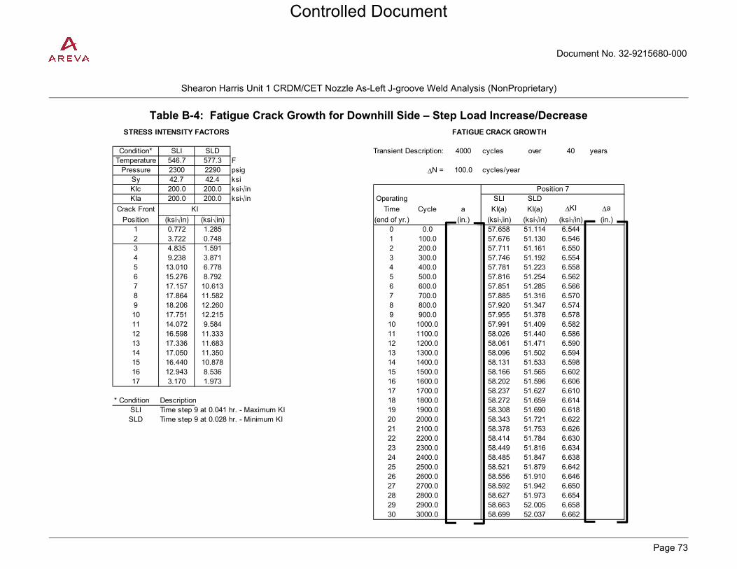
Document No. 32-9215680-000
PROPRIETARY
Shearon Harris Unit 1 CRDM/CET Nozzle As-Left J-groove Weld Analysis (NonProprietary)
Page 73
Table B-4: Fatigue Crack Growth for Downhill Side – Step Load Increase/Decrease
STRESS INTENSITY FACTORS FATIGUE CRACK GROWTH
Condition* SLI SLD Transient Description: 4000 cycles over 40 yearsTemperature 546.7 577.3 F
Pressure 2300 2290 psig ΔN = 100.0 cycles/yearSy 42.7 42.4 ksiKIc 200.0 200.0 ksi√inKIa 200.0 200.0 ksi√in Operating SLI SLD
Crack Front Time Cycle a KI(a) KI(a) ΔKI Δa
Position (ksi√in) (ksi√in) (end of yr.) (in.) (ksi√in) (ksi√in) (ksi√in) (in.)1 0.772 1.285 0 0.0 57.658 51.114 6.5442 3.722 0.748 1 100.0 57.676 51.130 6.5463 4.835 1.591 2 200.0 57.711 51.161 6.5504 9.238 3.871 3 300.0 57.746 51.192 6.5545 13.010 6.778 4 400.0 57.781 51.223 6.5586 15.276 8.792 5 500.0 57.816 51.254 6.5627 17.157 10.613 6 600.0 57.851 51.285 6.5668 17.864 11.582 7 700.0 57.885 51.316 6.5709 18.206 12.260 8 800.0 57.920 51.347 6.57410 17.751 12.215 9 900.0 57.955 51.378 6.57811 14.072 9.584 10 1000.0 57.991 51.409 6.58212 16.598 11.333 11 1100.0 58.026 51.440 6.58613 17.336 11.683 12 1200.0 58.061 51.471 6.59014 17.050 11.350 13 1300.0 58.096 51.502 6.59415 16.440 10.878 14 1400.0 58.131 51.533 6.59816 12.943 8.536 15 1500.0 58.166 51.565 6.60217 3.170 1.973 16 1600.0 58.202 51.596 6.606
17 1700.0 58.237 51.627 6.610* Condition Description 18 1800.0 58.272 51.659 6.614
SLI Time step 9 at 0.041 hr. - Maximum KI 19 1900.0 58.308 51.690 6.618SLD Time step 9 at 0.028 hr. - Minimum KI 20 2000.0 58.343 51.721 6.622
21 2100.0 58.378 51.753 6.62622 2200.0 58.414 51.784 6.63023 2300.0 58.449 51.816 6.63424 2400.0 58.485 51.847 6.63825 2500.0 58.521 51.879 6.64226 2600.0 58.556 51.910 6.64627 2700.0 58.592 51.942 6.65028 2800.0 58.627 51.973 6.65429 2900.0 58.663 52.005 6.65830 3000.0 58.699 52.037 6.662
Position 7
KI
Controlled Document

Document No. 32-9215680-000
PROPRIETARY
Shearon Harris Unit 1 CRDM/CET Nozzle As-Left J-groove Weld Analysis (NonProprietary)
Page 74
Table B-5: Fatigue Crack Growth for Downhill Side – Turbine Roll Test STRESS INTENSITY FACTORS FATIGUE CRACK GROWTH
Condition* TRT1 TRT2 Transient Description: 80 cycles over 40 yearsTemperature 443.4 557.4 F
Pressure 1692 2317 psig ΔN = 2.0 cycles/yearSy 43.8 42.6 ksiKIc 200.0 200.0 ksi√inKIa 200.0 200.0 ksi√in Operating TRT1 TRT2
Crack Front Time Cycle a KI(a) KI(a) ΔKI Δa
Position (ksi√in) (ksi√in) (end of yr.) (in.) (ksi√in) (ksi√in) (ksi√in) (in.)1 -0.097 1.296 0 0.0 64.359 49.628 14.7312 7.596 0.314 1 2.0 64.381 49.645 14.7363 8.926 1.073 2 4.0 64.419 49.675 14.7454 15.799 2.965 3 6.0 64.458 49.705 14.7545 20.199 5.609 4 8.0 64.497 49.735 14.7636 22.374 7.456 5 10.0 64.536 49.765 14.7727 23.858 9.127 6 12.0 64.575 49.795 14.7808 23.895 10.028 7 14.0 64.614 49.825 14.7899 23.591 10.686 8 16.0 64.653 49.855 14.79810 22.575 10.691 9 18.0 64.692 49.885 14.80711 18.078 8.372 10 20.0 64.732 49.915 14.81612 21.311 9.916 11 22.0 64.771 49.945 14.82513 22.588 10.205 12 24.0 64.810 49.976 14.83414 22.546 9.905 13 26.0 64.849 50.006 14.84315 21.928 9.491 14 28.0 64.888 50.036 14.85216 17.326 7.446 15 30.0 64.928 50.067 14.86117 4.367 1.684 16 32.0 64.967 50.097 14.870
17 34.0 65.007 50.127 14.879* Condition Description 18 36.0 65.046 50.158 14.888
TRT1 Time step 5 at 0.278 hr. - Maximum KI 19 38.0 65.085 50.188 14.897TRT2 Time step 8 at 1.418 hr. - Minimum KI 20 40.0 65.125 50.219 14.906
21 42.0 65.165 50.249 14.91522 44.0 65.204 50.280 14.92423 46.0 65.244 50.310 14.93424 48.0 65.283 50.341 14.94325 50.0 65.323 50.371 14.95226 52.0 65.363 50.402 14.96127 54.0 65.403 50.433 14.97028 56.0 65.443 50.464 14.97929 58.0 65.482 50.494 14.98830 60.0 65.522 50.525 14.997
Position 7
KI
Controlled Document

Document No. 32-9215680-000
PROPRIETARY
Shearon Harris Unit 1 CRDM/CET Nozzle As-Left J-groove Weld Analysis (NonProprietary)
Page 75
Table B-6: Fatigue Crack Growth for Downhill Side – Refueling
STRESS INTENSITY FACTORS FATIGUE CRACK GROWTH
Condition* RF1 RF2 Transient Description: 80 cycles over 40 yearsTemperature 32.0 140.0 F
Pressure 0 0 psig ΔN = 2.0 cycles/yearSy 50.0 48.5 ksiKIc 63.5 200.0 ksi√inKIa 43.2 105.3 ksi√in Operating RF1 RF2
Crack Front Time Cycle a KI(a) KI(a) ΔKI Δa
Position (ksi√in) (ksi√in) (end of yr.) (in.) (ksi√in) (ksi√in) (ksi√in) (in.)1 -1.034 0.410 0 0.0 54.137 37.685 16.4522 6.136 -1.478 1 2.0 54.156 37.698 16.4583 6.728 -1.554 2 4.0 54.189 37.721 16.4684 11.118 -2.447 3 6.0 54.222 37.744 16.4785 12.933 -2.684 4 8.0 54.254 37.767 16.4886 13.508 -2.754 5 10.0 54.287 37.790 16.4987 13.636 -2.816 6 12.0 54.320 37.812 16.5088 13.111 -2.783 7 14.0 54.353 37.835 16.5189 12.453 -2.669 8 16.0 54.386 37.858 16.52810 11.656 -2.515 9 18.0 54.419 37.881 16.53811 9.511 -2.035 10 20.0 54.452 37.904 16.54812 11.218 -2.375 11 22.0 54.485 37.927 16.55813 12.125 -2.502 12 24.0 54.517 37.950 16.56814 12.312 -2.456 13 26.0 54.551 37.973 16.57815 12.086 -2.355 14 28.0 54.584 37.996 16.58816 9.579 -1.852 15 30.0 54.617 38.019 16.59817 2.556 -0.538 16 32.0 54.650 38.042 16.608
17 34.0 54.683 38.065 16.618* Condition Description 18 36.0 54.716 38.088 16.628
RF1 Time step 7 at 0.171 hr. - Maximum KI 19 38.0 54.749 38.111 16.638RF2 Time step 1 at 0.0001 hr. - Minimum KI 20 40.0 54.783 38.134 16.648
21 42.0 54.816 38.158 16.65822 44.0 54.849 38.181 16.66823 46.0 54.882 38.204 16.67924 48.0 54.916 38.227 16.68925 50.0 54.949 38.250 16.69926 52.0 54.983 38.274 16.70927 54.0 55.016 38.297 16.71928 56.0 55.050 38.320 16.72929 58.0 55.083 38.344 16.74030 60.0 55.117 38.367 16.750
Position 7
KI
Controlled Document

Document No. 32-9215680-000
PROPRIETARY
Shearon Harris Unit 1 CRDM/CET Nozzle As-Left J-groove Weld Analysis (NonProprietary)
Page 76
Table B-7: Fatigue Crack Growth for Downhill Side – Loss of Load
STRESS INTENSITY FACTORS FATIGUE CRACK GROWTH
Condition* LL1 LL2 Transient Description: 210 cycles over 40 yearsTemperature 575.8 588.8 F
Pressure 2710 1844 psig ΔN = 5.25 cycles/yearSy 42.4 42.2 ksiKIc 200.0 200.0 ksi√inKIa 200.0 200.0 ksi√in Operating LL1 LL2
Crack Front Time Cycle a KI(a) KI(a) ΔKI Δa
Position (ksi√in) (ksi√in) (end of yr.) (in.) (ksi√in) (ksi√in) (ksi√in) (in.)1 0.950 1.766 0 0.0 58.834 42.239 16.5952 3.481 -2.663 1 5.3 58.857 42.255 16.6013 4.682 -2.204 2 10.5 58.892 42.281 16.6114 9.183 -2.532 3 15.8 58.928 42.306 16.6215 13.346 -0.958 4 21.0 58.963 42.332 16.6316 15.991 0.418 5 26.3 58.999 42.357 16.6427 18.333 1.738 6 31.5 59.035 42.383 16.6528 19.392 2.668 7 36.8 59.070 42.409 16.6629 19.973 3.496 8 42.0 59.106 42.434 16.67210 19.585 3.858 9 47.3 59.142 42.460 16.68211 15.468 2.902 10 52.5 59.177 42.486 16.69212 18.216 3.502 11 57.8 59.213 42.511 16.70213 18.870 3.448 12 63.0 59.249 42.537 16.71214 18.370 3.223 13 68.3 59.285 42.563 16.72215 17.573 3.041 14 73.5 59.321 42.589 16.73216 13.802 2.360 15 78.8 59.357 42.614 16.74217 3.440 0.326 16 84.0 59.393 42.640 16.753
17 89.3 59.429 42.666 16.763* Condition Description 18 94.5 59.465 42.692 16.773
LL1 Time step 2 at 0.003 hr. - Maximum KI 19 99.8 59.501 42.718 16.783LL2 Time step 12 at 0.033 hr. - Minimum KI 20 105.0 59.537 42.744 16.793
21 110.3 59.573 42.770 16.80422 115.5 59.610 42.796 16.81423 120.8 59.646 42.822 16.82424 126.0 59.682 42.848 16.83425 131.3 59.718 42.874 16.84426 136.5 59.755 42.900 16.85527 141.8 59.791 42.926 16.86528 147.0 59.828 42.952 16.87529 152.3 59.864 42.978 16.88630 157.5 59.900 43.005 16.896
Position 7
KI
Controlled Document

Document No. 32-9215680-000
PROPRIETARY
Shearon Harris Unit 1 CRDM/CET Nozzle As-Left J-groove Weld Analysis (NonProprietary)
Page 77
Table B-8: Fatigue Crack Growth for Downhill Side – Loss of Power
STRESS INTENSITY FACTORS FATIGUE CRACK GROWTH
Condition* LP1 LP2 Transient Description: 100 cycles over 40 yearsTemperature 553.8 600.5 F
Pressure 2295 2464 psig ΔN = 2.5 cycles/yearSy 42.7 42.1 ksiKIc 200.0 200.0 ksi√inKIa 200.0 200.0 ksi√in Operating LP1 LP2
Crack Front Time Cycle a KI(a) KI(a) ΔKI Δa
Position (ksi√in) (ksi√in) (end of yr.) (in.) (ksi√in) (ksi√in) (ksi√in) (in.)1 0.946 1.583 0 0.0 54.961 47.394 7.5672 2.604 -0.933 1 2.5 54.986 47.416 7.5703 3.602 -0.235 2 5.0 55.019 47.444 7.5754 7.174 0.851 3 7.5 55.053 47.473 7.5805 10.560 3.271 4 10.0 55.086 47.502 7.5846 12.672 5.130 5 12.5 55.119 47.530 7.5897 14.460 6.893 6 15.0 55.152 47.559 7.5938 15.213 7.988 7 17.5 55.186 47.588 7.5989 15.652 8.849 8 20.0 55.219 47.617 7.60310 15.355 9.056 9 22.5 55.253 47.645 7.60711 12.150 7.048 10 25.0 55.286 47.674 7.61212 14.353 8.381 11 27.5 55.319 47.703 7.61613 14.958 8.536 12 30.0 55.353 47.732 7.62114 14.686 8.199 13 32.5 55.386 47.761 7.62615 14.157 7.823 14 35.0 55.420 47.790 7.63016 11.141 6.120 15 37.5 55.454 47.819 7.63517 2.671 1.294 16 40.0 55.487 47.848 7.639
17 42.5 55.521 47.877 7.644* Condition Description 18 45.0 55.555 47.906 7.649
LP1 Time step 2 at 0.003 hr. - Maximum KI 19 47.5 55.588 47.935 7.653LP2 Time step 11 at 0.053 hr. - Minimum KI 20 50.0 55.622 47.964 7.658
21 52.5 55.656 47.993 7.66322 55.0 55.690 48.022 7.66723 57.5 55.723 48.052 7.67224 60.0 55.757 48.081 7.67725 62.5 55.791 48.110 7.68126 65.0 55.825 48.139 7.68627 67.5 55.859 48.169 7.69128 70.0 55.893 48.198 7.69529 72.5 55.927 48.227 7.70030 75.0 55.961 48.257 7.705
Position 7
KI
Controlled Document
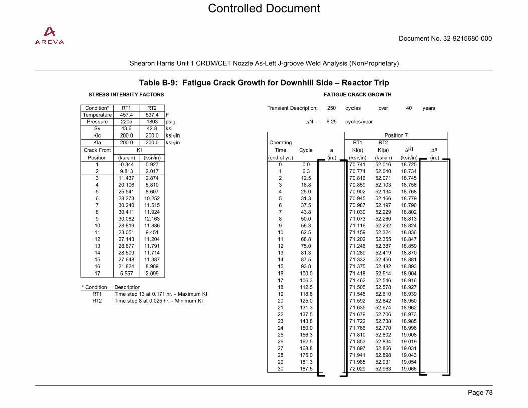
Document No. 32-9215680-000
PROPRIETARY
Shearon Harris Unit 1 CRDM/CET Nozzle As-Left J-groove Weld Analysis (NonProprietary)
Page 78
Table B-9: Fatigue Crack Growth for Downhill Side – Reactor Trip
STRESS INTENSITY FACTORS FATIGUE CRACK GROWTH
Condition* RT1 RT2 Transient Description: 250 cycles over 40 yearsTemperature 457.4 537.4 F
Pressure 2205 1803 psig ΔN = 6.25 cycles/yearSy 43.6 42.8 ksiKIc 200.0 200.0 ksi√inKIa 200.0 200.0 ksi√in Operating RT1 RT2
Crack Front Time Cycle a KI(a) KI(a) ΔKI Δa
Position (ksi√in) (ksi√in) (end of yr.) (in.) (ksi√in) (ksi√in) (ksi√in) (in.)1 -0.344 0.927 0 0.0 70.741 52.016 18.7252 9.813 2.017 1 6.3 70.774 52.040 18.7343 11.437 2.874 2 12.5 70.816 52.071 18.7454 20.106 5.810 3 18.8 70.859 52.103 18.7565 25.541 8.607 4 25.0 70.902 52.134 18.7686 28.273 10.252 5 31.3 70.945 52.166 18.7797 30.240 11.515 6 37.5 70.987 52.197 18.7908 30.411 11.924 7 43.8 71.030 52.229 18.8029 30.082 12.163 8 50.0 71.073 52.260 18.81310 28.819 11.886 9 56.3 71.116 52.292 18.82411 23.051 9.451 10 62.5 71.159 52.324 18.83612 27.143 11.204 11 68.8 71.202 52.355 18.84713 28.677 11.791 12 75.0 71.246 52.387 18.85914 28.509 11.714 13 81.3 71.289 52.419 18.87015 27.648 11.387 14 87.5 71.332 52.450 18.88116 21.824 8.989 15 93.8 71.375 52.482 18.89317 5.557 2.099 16 100.0 71.418 52.514 18.904
17 106.3 71.462 52.546 18.916* Condition Description 18 112.5 71.505 52.578 18.927
RT1 Time step 13 at 0.171 hr. - Maximum KI 19 118.8 71.548 52.610 18.939RT2 Time step 8 at 0.025 hr. - Minimum KI 20 125.0 71.592 52.642 18.950
21 131.3 71.635 52.674 18.96222 137.5 71.679 52.706 18.97323 143.8 71.722 52.738 18.98524 150.0 71.766 52.770 18.99625 156.3 71.810 52.802 19.00826 162.5 71.853 52.834 19.01927 168.8 71.897 52.866 19.03128 175.0 71.941 52.898 19.04329 181.3 71.985 52.931 19.05430 187.5 72.029 52.963 19.066
Position 7
KI
Controlled Document

Document No. 32-9215680-000
PROPRIETARY
Shearon Harris Unit 1 CRDM/CET Nozzle As-Left J-groove Weld Analysis (NonProprietary)
Page 79
Table B-10: Fatigue Crack Growth for Downhill Side – Inadvertent Depressurization
STRESS INTENSITY FACTORS FATIGUE CRACK GROWTH
Condition* ID1 ID2 Transient Description: 100 cycles over 40 yearsTemperature 557.4 556.6 F
Pressure 2317 1161 psig ΔN = 2.5 cycles/yearSy 42.6 42.6 ksiKIc 200.0 200.0 ksi√inKIa 200.0 200.0 ksi√in Operating ID1 ID2
Crack Front Time Cycle a KI(a) KI(a) ΔKI Δa
Position (ksi√in) (ksi√in) (end of yr.) (in.) (ksi√in) (ksi√in) (ksi√in) (in.)1 0.944 1.606 0 0.0 55.203 40.508 14.6952 2.677 -2.583 1 2.5 55.235 40.531 14.7033 3.690 -2.226 2 5.0 55.268 40.556 14.7124 7.328 -2.753 3 7.5 55.301 40.580 14.7215 10.757 -1.643 4 10.0 55.335 40.605 14.7306 12.894 -0.738 5 12.5 55.368 40.629 14.7397 14.702 0.007 6 15.0 55.402 40.654 14.7488 15.463 0.486 7 17.5 55.435 40.678 14.7579 15.902 1.001 8 20.0 55.468 40.703 14.76610 15.598 1.266 9 22.5 55.502 40.727 14.77511 12.345 0.914 10 25.0 55.536 40.752 14.78412 14.583 1.172 11 27.5 55.569 40.777 14.79213 15.199 1.177 12 30.0 55.603 40.801 14.80114 14.922 1.172 13 32.5 55.637 40.826 14.81015 14.385 1.175 14 35.0 55.670 40.851 14.81916 11.320 0.928 15 37.5 55.704 40.876 14.82817 2.717 -0.029 16 40.0 55.738 40.900 14.837
17 42.5 55.772 40.925 14.846* Condition Description 18 45.0 55.805 40.950 14.855
ID1 Time step 1 at 0.0001 hr. - Maximum KI 19 47.5 55.839 40.975 14.864ID2 Time step 9 at 0.022 hr. - Minimum KI 20 50.0 55.873 41.000 14.873
21 52.5 55.907 41.025 14.88222 55.0 55.941 41.050 14.89123 57.5 55.975 41.075 14.90124 60.0 56.009 41.100 14.91025 62.5 56.043 41.125 14.91926 65.0 56.077 41.150 14.92827 67.5 56.111 41.175 14.93728 70.0 56.146 41.200 14.94629 72.5 56.180 41.225 14.95530 75.0 56.214 41.250 14.964
Position 7
KI
Controlled Document

Document No. 32-9215680-000
PROPRIETARY
Shearon Harris Unit 1 CRDM/CET Nozzle As-Left J-groove Weld Analysis (NonProprietary)
Page 80
Table B-11: Fatigue Crack Growth for Downhill Side – Excessive Feedwater Flow
STRESS INTENSITY FACTORS FATIGUE CRACK GROWTH
Condition* EFF1 EFF2 Transient Description: 40 cycles over 40 yearsTemperature 448.6 557.4 F
Pressure 1809 2317 psig ΔN = 1.0 cycles/yearSy 43.7 42.6 ksiKIc 200.0 200.0 ksi√inKIa 200.0 200.0 ksi√in Operating EFF1 EFF2
Crack Front Time Cycle a KI(a) KI(a) ΔKI Δa
Position (ksi√in) (ksi√in) (end of yr.) (in.) (ksi√in) (ksi√in) (ksi√in) (in.)1 -0.519 0.944 0 0.0 65.553 55.203 10.3502 9.452 2.677 1 1.0 65.592 55.236 10.3563 10.871 3.690 2 2.0 65.632 55.269 10.3624 18.778 7.328 3 3.0 65.672 55.303 10.3695 23.040 10.757 4 4.0 65.711 55.336 10.3756 24.576 12.894 5 5.0 65.751 55.370 10.3817 25.052 14.702 6 6.0 65.791 55.403 10.3888 24.101 15.463 7 7.0 65.830 55.437 10.3949 23.123 15.902 8 8.0 65.870 55.470 10.40010 21.900 15.598 9 9.0 65.910 55.504 10.40611 17.871 12.345 10 10.0 65.950 55.537 10.41312 21.256 14.583 11 11.0 65.990 55.571 10.41913 23.048 15.199 12 12.0 66.030 55.604 10.42514 23.529 14.922 13 13.0 66.070 55.638 10.43215 23.259 14.385 14 14.0 66.110 55.672 10.43816 18.487 11.320 15 15.0 66.150 55.706 10.44417 4.524 2.717 16 16.0 66.190 55.739 10.451
17 17.0 66.230 55.773 10.457* Condition Description 18 18.0 66.270 55.807 10.463
EFF1 Time step 4 at 0.013 hr. - Maximum KI 19 19.0 66.310 55.841 10.470EFF2 Time step 1 at 0.0001 hr. - Minimum KI 20 20.0 66.351 55.875 10.476
21 21.0 66.391 55.909 10.48222 22.0 66.431 55.943 10.48923 23.0 66.472 55.977 10.49524 24.0 66.512 56.011 10.50125 25.0 66.553 56.045 10.50826 26.0 66.593 56.079 10.51427 27.0 66.634 56.113 10.52128 28.0 66.674 56.147 10.52729 29.0 66.715 56.181 10.53330 30.0 66.756 56.216 10.540
Position 7
KI
Controlled Document

Document No. 32-9215680-000
PROPRIETARY
Shearon Harris Unit 1 CRDM/CET Nozzle As-Left J-groove Weld Analysis (NonProprietary)
Page 81
Table B-12: Fatigue Crack Growth for Downhill Side – Leak Test STRESS INTENSITY FACTORS FATIGUE CRACK GROWTH
Condition* LT1 LT2 Transient Description: 280 cycles over 40 yearsTemperature 238.0 82.0 F
Pressure 2351 602 psig ΔN = 7.0 cycles/yearSy 46.4 50.0 ksiKIc 200.0 115.6 ksi√inKIa 200.0 60.6 ksi√in Operating LT1 LT2
Crack Front Time Cycle a KI(a) KI(a) ΔKI Δa
Position (ksi√in) (ksi√in) (end of yr.) (in.) (ksi√in) (ksi√in) (ksi√in) (in.)1 -0.484 -0.180 0 0.0 64.403 46.197 18.2062 7.656 1.843 1 7.0 64.442 46.225 18.2173 8.820 2.100 2 14.0 64.481 46.253 18.2284 15.468 3.646 3 21.0 64.520 46.281 18.2395 19.687 4.609 4 28.0 64.559 46.309 18.2506 21.987 5.170 5 35.0 64.598 46.337 18.2617 23.902 5.696 6 42.0 64.637 46.365 18.2728 24.423 5.902 7 49.0 64.676 46.393 18.2839 24.437 5.952 8 56.0 64.715 46.421 18.29410 23.571 5.765 9 63.0 64.754 46.449 18.30511 18.741 4.566 10 70.0 64.793 46.477 18.31612 22.027 5.351 11 77.0 64.832 46.505 18.32713 23.041 5.545 12 84.0 64.872 46.533 18.33814 22.643 5.386 13 91.0 64.911 46.561 18.35015 21.785 5.139 14 98.0 64.950 46.589 18.36116 17.137 4.030 15 105.0 64.990 46.618 18.37217 4.398 1.055 16 112.0 65.029 46.646 18.383
17 119.0 65.068 46.674 18.394* Condition Description 18 126.0 65.108 46.703 18.405
LT1 Time step 6 at 3.92 hr. - Maximum KI 19 133.0 65.147 46.731 18.416LT2 Time step 2 at 0.12 hr. - Minimum KI 20 140.0 65.187 46.759 18.428
21 147.0 65.227 46.788 18.43922 154.0 65.266 46.816 18.45023 161.0 65.306 46.845 18.46124 168.0 65.346 46.873 18.47225 175.0 65.385 46.902 18.48426 182.0 65.425 46.930 18.49527 189.0 65.465 46.959 18.50628 196.0 65.505 46.987 18.51729 203.0 65.545 47.016 18.52930 210.0 65.585 47.045 18.540
Position 7
KI
Controlled Document

Document No. 32-9215680-000
PROPRIETARY
Shearon Harris Unit 1 CRDM/CET Nozzle As-Left J-groove Weld Analysis (NonProprietary)
Page 82
Table B-13: Stress Intensification Factors for Downhill Side – Faulted Conditions
STRESS INTENSITY FACTORS TOTAL STRESS INTENSITY FACTORSFOR OPERATING CONDITIONS WITH RESIDUAL STRESS
Condition* LLOCA LSLBTemperature 32.0 207.8 F
Pressure 60 1316 psig ao = 2.1482 in.
Sy 50.0 46.9 ksiKIc 63.5 200.0 ksi√inKIa 43.2 200.0 ksi√in Condition* LLOCA LSLB
Crack Front Crack Front
Position (ksi√in) (ksi√in) Position (ksi√in) (ksi√in)1 -6.103 -3.533 1 -7.804 -5.2342 38.630 26.671 2 52.562 40.6033 42.411 29.689 3 58.128 45.4064 70.343 50.026 4 97.521 77.2045 81.924 59.828 5 115.814 93.7186 85.195 63.651 6 122.799 101.2557 85.364 65.558 7 125.865 106.0598 81.305 64.020 8 121.403 104.1189 76.653 61.644 9 114.291 99.28210 71.333 58.060 10 104.780 91.50711 58.183 46.864 11 82.856 71.53712 68.598 55.118 12 96.126 82.64613 74.395 58.941 13 101.321 85.86714 75.853 59.256 14 100.242 83.64515 74.663 57.792 15 96.364 79.49316 59.246 45.712 16 76.014 62.48017 15.675 12.059 17 21.451 17.835
* Condition DescriptionLLOCA Time step 15 at 0.03889 hr. (140 sec.) - Maximum KILSLB Time step 9 at 0.09222 hr. (332 sec.) - Maximum KI
KI KI
Controlled Document

Document No. 32-9215680-000
PROPRIETARY
Shearon Harris Unit 1 CRDM/CET Nozzle As-Left J-groove Weld Analysis (NonProprietary)
Page 83
Table B-14: EPFM Evaluations for Downhill Side – Reactor Trip
EPFM Equations: Jmat = C(Δa)m C =
Tmat = (E/σf2)*Cm(Δa)m-1 m =
Japp = [KI'(ae)]2/E'
Tapp = (E/σf2)*(dJapp/da)
Ductile Crack Growth Stability Criterion: Tapp < Tmat
At instability: Tapp = Tmat
KI*p KI*s KI*(a) ae KI'(ae) Japp Tapp Stable?
Primary Secondary (ksi√in) (ksi√in) (ksi√in) (in.) (ksi√in) (kips/in)1.00 1.00 28.672 43.367 72.039 2.3726 74.344 0.185 0.591 Yes2.00 1.00 57.345 43.367 100.711 2.5108 106.918 0.382 1.223 Yes3.00 1.50 86.017 65.050 151.067 2.8646 171.305 0.982 3.139 Yes8.00 1.00 229.378 43.367 272.745 4.3038 379.096 4.808 15.371 Yes15.00 1.00 430.084 43.367 473.451 8.4835 923.906 28.558 91.296 No
Iterate on safety factor until Tapp = Tmat to determine Jinstability :
Jinstability Tapp Tmat
4.3064 4.3064 123.476 186.756 310.232 4.9137 460.742 7.102 22.705 22.705
at Jmat = 0.982 kips/in, Tmat = 242.047
Applied J-Integral Criterion: Japp < J0.1
where, J0.1 = Jmat at Δa = 0.1 in.
KI*p KI*s KI*(a) ae KI'(ae) Japp J0.1 OK?
Primary Secondary (ksi√in) (ksi√in) (ksi√in) (in.) (ksi√in) (kips/in) (kips/in)1.50 1.00 43.008 43.367 86.375 2.4360 90.321 0.273 2.473 Yes
Safety Factors
Safety Factors
Controlled Document

Document No. 32-9215680-000
PROPRIETARY
Shearon Harris Unit 1 CRDM/CET Nozzle As-Left J-groove Weld Analysis (NonProprietary)
Page 84
Figure B-1: J-T Diagram for Downhill Side – Reactor Trip
0
1
2
3
4
5
6
7
8
9
10
0 5 10 15 20 25 30 35 40 45 50
J-In
teg
ral (
kip
s/in
)
Tearing Modulus
J-T Applied
J-T Material
SF = 3 & 1.5
Instablility Point
Controlled Document

Document No. 32-9215680-000
PROPRIETARY
Shearon Harris Unit 1 CRDM/CET Nozzle As-Left J-groove Weld Analysis (NonProprietary)
Page 85
Table B-15: EPFM Evaluations for Downhill Side – Refueling
EPFM Equations: Jmat = C(Δa)m C =
Tmat = (E/σf2)*Cm(Δa)m-1 m =
Japp = [KI'(ae)]2/E'
Tapp = (E/σf2)*(dJapp/da)
Ductile Crack Growth Stability Criterion: Tapp < Tmat
At instability: Tapp = Tmat
KI*p KI*s KI*(a) ae KI'(ae) Japp Tapp Stable?
Primary Secondary (ksi√in) (ksi√in) (ksi√in) (in.) (ksi√in) (kips/in)1.00 1.00 0.000 55.130 55.130 2.2923 55.923 0.097 0.302 Yes3.00 1.50 0.000 82.695 82.695 2.3729 85.346 0.227 0.704 Yes10.00 3.00 0.000 165.391 165.391 2.8082 185.692 1.075 3.335 Yes10.00 4.00 0.000 220.521 220.521 3.2597 266.751 2.218 6.881 Yes10.00 7.00 0.000 385.912 385.912 5.3881 600.168 11.228 34.834 No
Iterate on safety factor until Tapp = Tmat to determine Jinstability :
Jinstability Tapp Tmat
6.0382 6.0382 0.000 332.889 332.889 4.5793 477.273 7.101 22.029 22.029
at Jmat = 0.227 kips/in, Tmat = 1357.163
Applied J-Integral Criterion: Japp < J0.1
where, J0.1 = Jmat at Δa = 0.1 in.
KI*p KI*s KI*(a) ae KI'(ae) Japp J0.1 OK?
Primary Secondary (ksi√in) (ksi√in) (ksi√in) (in.) (ksi√in) (kips/in) (kips/in)1.50 1.00 0.000 55.130 55.130 2.2923 55.923 0.097 2.474 Yes
Safety Factors
Safety Factors
Controlled Document

Document No. 32-9215680-000
PROPRIETARY
Shearon Harris Unit 1 CRDM/CET Nozzle As-Left J-groove Weld Analysis (NonProprietary)
Page 86
Figure B-2: J-T Diagram for Downhill Side – Refueling
0
1
2
3
4
5
6
7
8
9
10
0 5 10 15 20 25 30 35 40 45 50
J-In
teg
ral (
kip
s/in
)
Tearing Modulus
J-T Applied
J-T Material
SF = 3 & 1.5
Instablility Point
Controlled Document

Document No. 32-9215680-000
PROPRIETARY
Shearon Harris Unit 1 CRDM/CET Nozzle As-Left J-groove Weld Analysis (NonProprietary)
Page 87
Table B-16: EPFM Evaluations for Downhill Side – LLOCA
EPFM Equations: Jmat = C(Δa)m C =
Tmat = (E/σf2)*Cm(Δa)m-1 m =
Japp = [KI'(ae)]2/E'
Tapp = (E/σf2)*(dJapp/da)
Ductile Crack Growth Stability Criterion: Tapp < Tmat
At instability: Tapp = Tmat
KI*p KI*s KI*(a) ae KI'(ae) Japp Tapp Stable?
Primary Secondary (ksi√in) (ksi√in) (ksi√in) (in.) (ksi√in) (kips/in)1.00 1.00 0.780 76.629 77.409 2.3549 79.587 0.197 0.613 Yes1.50 1.00 1.170 76.629 77.799 2.3562 80.010 0.200 0.619 Yes
200.00 1.00 156.040 76.629 232.668 3.3765 286.443 2.558 7.935 Yes300.00 1.00 234.059 76.629 310.688 4.2761 430.443 5.776 17.918 Yes400.00 1.00 312.079 76.629 388.708 5.4341 607.088 11.489 35.642 No
Iterate on safety factor until Tapp = Tmat to determine Jinstability :
Jinstability Tapp Tmat
4.3004 4.3004 3.355 329.534 332.889 4.5793 477.273 7.101 22.029 22.029
at Jmat = 0.200 kips/in, Tmat = 1584.010
Applied J-Integral Criterion: Japp < J0.1
where, J0.1 = Jmat at Δa = 0.1 in.
KI*p KI*s KI*(a) ae KI'(ae) Japp J0.1 OK?
Primary Secondary (ksi√in) (ksi√in) (ksi√in) (in.) (ksi√in) (kips/in) (kips/in)1.50 1.00 1.170 76.629 77.799 2.3562 80.010 0.200 2.474 Yes
Safety Factors
Safety Factors
Controlled Document

Document No. 32-9215680-000
PROPRIETARY
Shearon Harris Unit 1 CRDM/CET Nozzle As-Left J-groove Weld Analysis (NonProprietary)
Page 88
Figure B-3: J-T Diagram for Downhill Side – LLOCA
0
1
2
3
4
5
6
7
8
9
10
0 5 10 15 20 25 30 35 40 45 50
J-In
teg
ral (
kip
s/in
)
Tearing Modulus
J-T Applied
J-T Material
SF = 1.5 & 1
Instablility Point
Controlled Document

20004-020 (10/21/2013)
Page 1 of 20
AREVA NP Inc.
Engineering Information Record
Document No.: 51 - 9215673 - 000
Corrosion Evaluation of Shearon Harris RV Head Penetration IDTB Weld Repair (NonProprietary)
Controlled Document
Controlled Document
A ARE VA
20004~020 (1 0/21/2013)
Document No.: 51-9215673-000
Corrosion Evaluation of Shearon Harris RV Head Penetration IDTB Weld Repair (NonProprietary)
Safety Related? IZJ YES D NO
Does this document establish design or technical requirements? 0 YES ~ NO
Does this document contain assumptions requiring verification? 0 YES cgj NO
Does this document contain Customer Required Format? DYES cgj 1' 0
Signature Block
Name and Title/Discipline Signature
P/LP, RILR, A-CRF, A Date
Pages/Sections Prepared/Reviewed/
Approved or Comments
R. S. Hosler _,.. Supervisor . ~ .£...._ Materials Engineering - ~ S. B. Davidsaver ·. ;_ J f),. A; J "~A EngineeriV ~ J./wV11C7\(IVI'"•'
Matedals Engineering B. V. Haibach Manager Materials & RCS Stmctural Analysis
p
R
A
Note: P/LP designates Preparer (P), Lead Preparer (LP) RILR designates Reviewer (R), Lead Reviewer (LR) A-CRF designates Project Manager Approver of Customer Required Format (A·CRF) A designates Approver/RTM- Verification of Reviewer Independel(ce
I Project Manager Approval of Customer References (N/A if ~ot applicable)
Name Title (printed or typed) (printed or typed) ~ignature
N/A Date
Page2

20004-020 (10/21/2013)
Document No.: 51-9215673-000
Corrosion Evaluation of Shearon Harris RV Head Penetration IDTB Weld Repair (NonProprietary)
Page 3
Record of Revision
Revision No.
Pages/Sections/ Paragraphs Changed Brief Description / Change Authorization
000 All Original Issue. The corresponding proprietary version is in AREVA document 51-9176114-001.
Controlled Document

Document No.: 51-9215673-000
Corrosion Evaluation of Shearon Harris RV Head Penetration IDTB Weld Repair (NonProprietary)
Page 4
Table of Contents
Page
SIGNATURE BLOCK ................................................................................................................................ 2
RECORD OF REVISION .......................................................................................................................... 3
LIST OF TABLES ..................................................................................................................................... 5
LIST OF FIGURES ................................................................................................................................... 6
1.0 PURPOSE ..................................................................................................................................... 7
2.0 BACKGROUND ............................................................................................................................ 7
3.0 KNOWN OCCURANCES OF EXPOSED CARBON/LOW ALLOY STEEL BASE METAL ......... 12
4.0 CORROSION OF EXPOSED LOW ALLOY STEEL AT LOCATION A ....................................... 13 4.1 General Corrosion of Exposed Base Metal ..................................................................... 13
4.1.1 Oxygen Level in the Repaired Area ............................................................... 13 4.1.2 General Corrosion Rate ................................................................................. 13 4.1.3 General Corrosion Rate in the HAZ ............................................................... 14
4.2 Crevice Corrosion of Exposed Base Metal ...................................................................... 14 4.3 Galvanic Corrosion of Exposed Base Metal .................................................................... 14 4.4 Stress Corrosion Cracking of Exposed Base Metal ........................................................ 15 4.5 Hydrogen Embrittlement of Exposed Base Metal ............................................................ 15
5.0 ESTIMATE OF FE RELEASE RATE FROM EXPOSED LOW ALLOY STEEL AT LOCATION A16 5.1 CRDM, CET, and Spare Nozzle Repairs ........................................................................ 16
6.0 CORROSION OF ALLOY 52M ................................................................................................... 18
7.0 CONCLUSIONS .......................................................................................................................... 19
8.0 REFERENCES ............................................................................................................................ 19
Controlled Document

Document No.: 51-9215673-000
Corrosion Evaluation of Shearon Harris RV Head Penetration IDTB Weld Repair (NonProprietary)
Page 5
List of Tables
Page
TABLE 5-1: ESTIMATED EXPOSED AREA OF LAS AND FE RELEASE RATE ................................. 17
Controlled Document

Document No.: 51-9215673-000
Corrosion Evaluation of Shearon Harris RV Head Penetration IDTB Weld Repair (NonProprietary)
Page 6
List of Figures
Page
FIGURE 2-1: CURRENT CONFIGURATION OF CRDM/CET/SPARE NOZZLE AT HNP (REFERENCE 2, STEP 1) ............................................................................................................................... 8
FIGURE 2-2: IDTB CRDM NOZZLE REPAIR CONFIGURATION [ ] INCLUDING REMEDIATION (SHOWN BEFORE REPLACEMENT
THERMAL SLEEVE ATTACHMENT FOR CLARITY) (REFERENCE 2, STEP 6) .................. 9 FIGURE 2-3: IDTB CRDM NOZZLE REPAIR CONFIGURATION [
] NO REMEDIATION SHOWN (SHOWN BEFORE REPLACEMENT THERMAL SLEEVE ATTACHMENT FOR CLARITY) (REFERENCE 2, STEP 5A) ............. 10
FIGURE 2-4: IDTB CRDM NOZZLE REPAIR CONFIGURATION (REFERENCE 2, STEP 7).............. 11
Controlled Document

Document No.: 51-9215673-000
Corrosion Evaluation of Shearon Harris RV Head Penetration IDTB Weld Repair (NonProprietary)
Page 7
1.0 PURPOSE
The purpose of this document is to evaluate potential corrosion concerns arising from the final geometrical configuration of the proposed inner diameter temper bead (IDTB) weld repair of the control rod drive mechanism (CRDM), core exit thermocouple (CET), and/or spare nozzle penetrations due to potential degradation at these potentially repaired locations. Sixty-five (65) nozzle reactor vessel closure head (RVCH) penetrations, including fifty-two (52) CRDM nozzles with thermal sleeves, four (4) CET nozzles with no thermal sleeves, and nine (9) spare locations with no thermal sleeves are potential locations for this repair to be performed [1]. The materials with potential corrosion concerns evaluated within this document include the low alloy steel RVCH exposed as well as the new Alloy 52M used to create a new weld during the proposed repair.
2.0 BACKGROUND
In December 2000, inspections of the Alloy 600 CRDM nozzle penetrations in the RVCH at a domestic pressurized water reactor (PWR) identified leakage in the region of the partial penetration weld between the RVCH and the CRDM nozzle. This leakage, identified as the result of primary water stress corrosion cracking (PWSCC), was repaired using manual grinding and welding. In February 2001, the manual repair of several CRDM nozzles at another domestic PWR with similar defects resulted in extensive radiation dose to the personnel due to the location and access limitations. Therefore, the Babcock & Wilcox (B&W) Owner’s Group (BWOG) commissioned Framatome (now AREVA) to provide an automated repair process that was ultimately implemented at a third domestic PWR [1].
Due to concerns that similar degradation at CRDM, CET, and spare nozzle locations may have occurred at Shearon Harris Unit 1, Progress Energy has contracted AREVA to adapt this repair for Shearon Harris as a contingency. In the current configuration (Figure 2-1 [2]), a leak of primary water through a PWSCC crack in a potentially susceptible Alloy 600 penetration or Alloy 82/182 J-groove weld could cause the buildup of boric acid on the outer portion of the RVCH. If required, the IDTB nozzle repair method shown in Figure 2-2, Figure 2-3,
and Figure 2-4 will be used [2]. Figure 2-2 depicts the proposed repair method [
] and after abrasive water jet machining (AWJM) remediation is performed. Figure 2-3
depicts the proposed repair method [
] Note that Figure 2-3 does not show the AWJM remediation. Both Figure 2-2 and Figure 2-3 are shown before replacement thermal sleeve attachment for clarity purposes. Figure 2-4 depicts the final repair, including the
replacement thermal sleeve (where applicable). [
] Therefore this drawing is applicable for the CRDM, CET, and spare locations described in Section 1.0 of this document. As stated in Section 1.0, the materials with potential corrosion concerns evaluated within this document include the low alloy steel RVCH exposed as well as the new Alloy 52M used to create a new weld during the proposed repair.
Controlled Document

Document No.: 51-9215673-000
Corrosion Evaluation of Shearon Harris RV Head Penetration IDTB Weld Repair (NonProprietary)
Page 8
Figure 2-1: Current Configuration of CRDM/CET/Spare Nozzle at HNP (Reference 2, Step 1)
Controlled Document
AREVA
Original Alloy 600 housing --------------.
Low Alloy Steel RVCH
Original J-Groove Weld
Original Thermal Sleeve

Document No.: 51-9215673-000
Corrosion Evaluation of Shearon Harris RV Head Penetration IDTB Weld Repair (NonProprietary)
Page 9
Figure 2-2: IDTB CRDM Nozzle Repair Configuration [
] including Remediation (Shown before Replacement Thermal Sleeve Attachment for Clarity) (Reference 2, Step 6)
Controlled Document

Document No.: 51-9215673-000
Corrosion Evaluation of Shearon Harris RV Head Penetration IDTB Weld Repair (NonProprietary)
Page 10
Figure 2-3: IDTB CRDM Nozzle Repair Configuration [
] no Remediation Shown (Shown before Replacement Thermal Sleeve Attachment for Clarity) (Reference 2, Step 5A)
Controlled Document

Document No.: 51-9215673-000
Corrosion Evaluation of Shearon Harris RV Head Penetration IDTB Weld Repair (NonProprietary)
Page 11
Figure 2-4: IDTB CRDM Nozzle Repair Configuration (Reference 2, Step 7)
Controlled Document

Document No.: 51-9215673-000
Corrosion Evaluation of Shearon Harris RV Head Penetration IDTB Weld Repair (NonProprietary)
Page 12
3.0 KNOWN OCCURANCES OF EXPOSED CARBON/LOW ALLOY STEEL BASE METAL
The primary reactor coolant system (RCS), the pressurizer, reactor vessel, and the steam generator are clad with either a stainless steel or nickel-base alloy in order to prevent corrosion of the carbon or LAS base metal. Throughout the operating history of domestic PWRs, there have been many cases where a localized area of the carbon or LAS base metal has been exposed to the primary coolant. Several such instances are listed below:
1960s Yankee-Rowe reactor vessel – Surveillance capsules fell from holder assemblies to the bottom of the vessel, releasing test specimens and other debris, leading to perforations in the cladding.
1990 Three Mile Island Unit 1 steam generator – Several tubes have separated within the tubesheet area exposing the tubesheet material to primary coolant. (LER 289-1990-005)
1990 ANO Unit 1 pressurizer – A leak was detected at the pressurizer upper level tap nozzle within the steam space in December 1990. The repair consisted of removing the outer section of the nozzle followed by welding a new section of nozzle to the OD of the pressurizer. (LER 313-1990-021)
1991 Oconee-Unit 1 steam generator – A misdrilled tubesheet hole in the upper tubesheet of one of the steam generators, during plugging operation in 1991, led to exposure of a small area of unclad tubesheet to primary coolant. [Note: This area of the tubesheet has since been “patched” and is no longer exposed to coolant.]
1993 McGuire-Unit 2 reactor vessel – A defect in the vessel cladding was discovered during an inspection in July 1993; the defect is believed to have occurred as a result of a pipe dropped in the vessel during construction (1975).
1993 SONGS-Unit 2 hot leg nozzle – A repair to a hot leg nozzle was completed during the 1993 outage at the SONGS Unit 2. This repair consisted of replacing a section of the existing Alloy 600 nozzle with a new nozzle
section fabrication from Alloy 690. A gap approximately [ ] wide exists between the two nozzle sections where the carbon steel base metal is exposed to the primary coolant. Verbal communication with SONGS personnel indicated that the hot leg nozzle containing this repair was removed and the exposed carbon steel examined.
1994 Calvert Cliffs-Unit 1 pressurizer – Two leaking heater nozzles in the lower head of the pressurizer were partially removed and the penetrations were plugged in 1994. (LER 317-1994-003)
1997 Oconee-Unit 1 OTSG manway – During the end-of-cycle (EOC) 17 refueling outage, a degraded area was observed in the “bore” of the 1B once through steam generator (OTSG). Subsequent inspection revealed a [ ] circumferential damaged area to the cladding surface of the manway opening. The exposure of the base metal was confirmed by etching.
2001 CRDM repairs at Oconee Unit 2, Oconee Unit 3, Crystal River Unit 3, Three Mile Island Unit 1, and Surry Unit 1. (LER 270-2001-002, 287-2001-003, 302-2001-004, 289-2001-002, 280-2001-003)
2002 CRDM repairs at Oconee Unit 1 and Oconee Unit 2. (LER 269-2002-003, 270-2002-002)
2003 CRDM/CEDM repairs at St. Lucie Unit 2 and Millstone Unit 2, half nozzle repairs of STP-1 bottom mounted instrument nozzles, half nozzle repairs of pressurizer instrument nozzles at Crystal River Unit 3. (LER 389-2003-002, 498-2003-003, 302-2003-003)
2005 Half-nozzle modification for the TMI-1 pressurizer vent nozzle.
In each of these instances, carbon or LAS base metal was exposed to primary coolant in a localized area. Each plant returned to normal operation with the base metal exposed; in the case of Yankee-Rowe, the vessel operated for roughly 30 years with the base metal exposed.
Controlled Document

Document No.: 51-9215673-000
Corrosion Evaluation of Shearon Harris RV Head Penetration IDTB Weld Repair (NonProprietary)
Page 13
4.0 CORROSION OF EXPOSED LOW ALLOY STEEL AT LOCATION A
Several types of corrosion can occur when carbon and LAS base metal are exposed to primary coolant. During operating conditions, the primary coolant is deaerated at high temperatures (550-650°F) depending on the location within the RCS. The following sections discuss the possible corrosion mechanisms for the exposed LAS base metal at Location A (see Figure 2-3 for depiction of Location A).
4.1 General Corrosion of Exposed Base Metal
General corrosion is defined as a type of corrosion attack (deterioration) uniformly distributed over a metal surface and corrosion that proceeds at approximately the same rate over a metal surface [3]. Stainless steels and nickel-base alloys (e.g., wrought Type 304, Type 316, Alloy 600, and Alloy 690 and their equivalent weld metals) are essentially unsusceptible to general corrosion in a PWR environment due to their passive protective surface layer. Carbon and LASs, however, may be susceptible to general corrosion depending on the service environment. The major factors affecting the general corrosion susceptibility of LAS are temperature, fluid velocity, boric acid concentration, and time. The general corrosion rates of carbon and LASs in aerated and deaerated conditions are discussed below.
4.1.1 Oxygen Level in the Repaired Area
4.1.2 General Corrosion Rate
Many investigators have reported corrosion rates of carbon and LAS in various environments [6, 7, 8, 9, 10, 11, 12, 13, 14, 15]. In several instances, the corrosion rates for carbon and LASs have been observed to be similar in PWR environments; this data is applicable to carbon and LAS materials such as A-302, SA-533 (the material of the Shearon Harris RVCH [1]), and SA-516 [6, 8, 9, 13]. The Electric Power Research Institute (EPRI) has published a handbook on boric acid corrosion [16]. This handbook summarizes the industry field experience with boric acid corrosion incidents, a discussion of boric acid corrosion mechanisms, and a compilation of all prior boric acid corrosion testing and results. In one evaluation, ASTM A302 Grade B was exposed to primary coolant in aerated and deaerated conditions [17]. It was shown that under deaerated conditions (i.e., during operation), the corrosion rate depended on temperature, fluid velocity, boric acid concentration, and time [17]. At the maximum velocity tested (36 ft/sec), the corrosion rate was determined to be 0.003 inch/year (ipy); this was the maximum corrosion rate reported in the report. Under static conditions (i.e., stagnant) at 650°F, a maximum corrosion rate of 0.0009 ipy was reported. In this same study at shutdown conditions (aerated, at low temperature), the maximum corrosion rate was determined to be 0.0015 inch for a two month shutdown, or 0.009 ipy [17].
Controlled Document

Document No.: 51-9215673-000
Corrosion Evaluation of Shearon Harris RV Head Penetration IDTB Weld Repair (NonProprietary)
Page 14
[
]
4.1.3 General Corrosion Rate in the HAZ
[
]
4.2 Crevice Corrosion of Exposed Base Metal
The environmental conditions in a crevice can become aggressive with time and can cause accelerated local corrosion. The proposed as-repaired geometry shown in Figure 2-3 is open and does not contain any crevices.
Experiments were conducted (not as a part of this work scope) to determine the crevice corrosion rate of LAS. The results indicate that the crevice corrosion rate for both aerated and deaerated conditions is less than the respective general corrosion rate [11, 17]. Operating experience from PWRs shows that crevice corrosion is not normally a problem in PWR systems with expected low oxygen contents [13].
[ ]
4.3 Galvanic Corrosion of Exposed Base Metal
Galvanic corrosion may occur when two dissimilar metals in contact are exposed to a conductive solution or coupled together. The three essential components to galvanic corrosion are 1) materials possessing different surface potential, 2) a common electrolyte, and 3) a common electrical path. The larger the potential difference between the metals, the greater the likelihood of galvanic corrosion. Low alloy and carbon steel are more anodic than stainless steels and nickel-base alloys [18] and could therefore be subject to galvanic attack when coupled and exposed to reactor coolant.
Controlled Document

Document No.: 51-9215673-000
Corrosion Evaluation of Shearon Harris RV Head Penetration IDTB Weld Repair (NonProprietary)
Page 15
Several corrosion tests were performed (not as a part of this work scope) to determine the influence of coupling. In one test, carbon steel specimens were coupled and uncoupled to stainless steel and exposed to simulated reactor shutdown conditions. The corrosion rates while coupled and uncoupled were determined to be similar [17]. Additionally, galvanic corrosion of carbon steel coupled to stainless steel in boric acid solution in the absence of oxygen should be quite low, therefore the galvanic corrosion rate should be low and the total corrosion is expected to be about equal to the general corrosion rate [17]. Austenitic stainless steels, such as Type 304, have approximately the same corrosion potential as nickel-base alloys such as Alloy 690. Therefore, galvanic corrosion studies of LAS and stainless steel give insight into the galvanic corrosion of LAS and nickel-base alloys. Specimens made from 5% chromium steel coupled to Type 304 stainless steel were exposed to aerated water at 500°F for 85 days (~2000 hours) with no evidence of galvanic corrosion. In the test above, the corrosion rates was note affected by coupling [15]. Additionally, results of the NRC’s boric acid corrosion test program have shown that the galvanic difference between ASTM A533 Grade B, Alloy 600, and 308 stainless steel is not significant enough to consider galvanic corrosion as a strong contributor to the overall boric acid corrosion process [19].
[
]
4.4 Stress Corrosion Cracking of Exposed Base Metal
Stress corrosion cracking (SCC) can only occur when the following three conditions are present:
• A susceptible material
• A tensile stress
• An aggressive environment
Under normal PWR conditions (deaerated), primary water is not a particularly aggressive environment for LAS. [
] This service environment does not generally support localized corrosion of LAS therefore the likelihood of a pit or notch forming which would contribute a stress
concentrator or SCC initiation site is negligible. Extensive experience with exposed LAS [
] has not resulted in any significant SCC. [
]
4.5 Hydrogen Embrittlement of Exposed Base Metal
Hydrogen embrittlement occurs when a material’s properties are degraded due to the presence of hydrogen. This type of damage usually occurs in combination with a stress, residual, applied, or otherwise. Hydrogen embrittlement is typically observed in high pressure hydrogen environments and in deformed metals and is characterized by ductility losses and lowering of the fracture toughness [3]. High pressure hydrogen environments are not typical of PWR systems and are defined as an environment with approximately 5,000-10,000 psi [20]. Although hydrogen is added to PWR water to scavenge oxygen (see Section 4.1.1 of this report), the primary contributor of hydrogen diffusion into the LAS is the corrosion process. Corrosion tests on LAS in deaerated boric acid solutions indicated that the maximum concentration of the hydrogen in the steel from the corrosion process was less than 2 ppm and did not increase with time [17]. The quantity of hydrogen that may accumulate at locations within the coolant system is not expected to induce hydrogen embrittlement in materials
at these locations. [
]
Controlled Document

Document No.: 51-9215673-000
Corrosion Evaluation of Shearon Harris RV Head Penetration IDTB Weld Repair (NonProprietary)
Page 16
5.0 ESTIMATE OF FE RELEASE RATE FROM EXPOSED LOW ALLOY STEEL AT LOCATION A
5.1 CRDM, CET, and Spare Nozzle Repairs
Based on Figure 2-3 of this report, the limiting dimensions after boring and AWJM for D and W are:
Controlled Document

Document No.: 51-9215673-000
Corrosion Evaluation of Shearon Harris RV Head Penetration IDTB Weld Repair (NonProprietary)
Page 17
The estimated exposed LAS surface area and the corresponding Fe release rate are summarized in Table 5-1.
Table 5-1: Estimated Exposed Area of LAS and Fe Release Rate
Controlled Document

Document No.: 51-9215673-000
Corrosion Evaluation of Shearon Harris RV Head Penetration IDTB Weld Repair (NonProprietary)
Page 18
6.0 CORROSION OF ALLOY 52M
Alloy 52M (Alloy 52 ‘modified’) is the specified IDTB weld repair for the CRDM/CET/spare nozzle penetrations. To better understand the potential corrosion concerns of Alloy 52M, information regarding the corrosion of Alloy 690 (the associated base metal to Alloy 52M) and Alloy 52 (the ‘base’ Alloy 52 not containing some of the alloying element of Alloy 52M) will also be presented. The corrosion resistance of Alloy 52M is expected to be similar to that of Alloy 52 and Alloy 690. The difference between these Alloy 52 and 52M is only minor alloying elements such as niobium and cobalt for enhanced weldability. The chromium content, which provides the corrosion resistance of the material, is similar. The corrosion resistance of Alloy 690 has been extensively studied as a result of numerous PWSCC failures in mill annealed Alloy 600 in primary water environments. As a result of Alloy 600 failures, Alloy 690 has been chosen by the nuclear industry as the replacement material of choice for Alloy 600 components.
A comprehensive review for the use of Alloy 690 in PWR systems cites numerous investigations and test results under a wide array of conditions, including both primary (high temperature deoxygenated water) and secondary coolant environments. The first Alloy 690 steam generator went online in May 1989 with no reported failures as to the date of that publication due to environmental degradation (August 1997) [23]. No environmental degradation of Alloy 690 or its related weld metals has been reported since the August 1997. Crevice and general corrosion of austenitic nickel-base materials is not expected to be of great concerns in typical PWR conditions [24].
Alloy 52M was tested (not as a part of this work scope) in accelerated corrosion conditions by testing a weld mockup that simulated nozzle safe end repairs. The testing consisted of 400°C (752°F) steam plus hydrogen doped with 30 ppm each of fluoride, chloride, and sulfate anions. The hydrogen partial pressure was controlled at approximately 75kPa with a total steam pressure of 20 MPa; this environment has been previously used to accelerate the simulated PWSCC of nickel-base alloys. After a cumulative exposure of 2051 hours (equivalent to 45.6 EFPY), no environmental degradation was detected on the surface of the Alloy 52M welds. Small microfissures on the surface of the Alloy 52M welds, stressed in tension, did not serve as initiation sites for environmental degradation, nor did they propagate during the tests. Stress corrosion cracks initiated in the also-tested Alloy 182 welds in exposure times less than one-fifth the total exposure time of the Alloy 52M specimens [25]. This study, along with many others [examples in References 26, 27, 28], indicate that the Alloy 52M weld
metal in the proposed repair [ ]
Controlled Document

Controlled Document
A AREVA Document No.: 51-9215673-000
Corrosion Evaluation of Shearon Harris RV Head Penetration IDTB Weld Repair (NonProprietary)
7.0 CONCLUSIONS The information presented above describes the potential corrosion mechanisms that may affect the exposed LAS in the proposed Shearon Harris RVCH penetration repair configuration in Figure 2-3. Based on this evaluation, the modification is found acceptable (as detailed below).
8.0 REFERENCES
1. AREV A 08-9172870-002, "Shearon Harris R VCH CRDM and CET Nozzle Penetration Modification."
2. AREVA 02-9175500E-005, "Shearon Harris CRDM ID Temberbead Weld Repair."
3. ASM Metals Handbook, Eleventh Edition, Volume 13A "Corrosion", 2003.
4. P. Pastina, et. al., "The Influence of Water Chemistry on the Radiolysis of the Primary Coolant Water in Pressurized Water Reactors," Journal ofNuclear Materials, 264 (1999) 309-318.
5. P. Scott, "A Review oflrradiation Assisted Stress Corrosion Cracking," Journal of Nuclear Materials, 211 (1994) 101-122.
6. Whitman, G. D. et. al., A Review of Current Practice in Design, Analysis, Materials, Fabrication, Inspection, and Test, ORNL-NSIC-21, ORNL, December~I~G"1 R.~H \1/).~/J">
7. Vreeland, D. C. et. al., "Corrosion of Carbon and Low-Alloy Steels in Out-of-Pile Boiling Water Reactor Environment," Corrosion, v17, June 1961, p. 269.
8. Vreeland, D. C. et. al., "Corrosion of Carbon Steel and Other Steels in Simulated Boiling-Water Reactor Environment: Phase II," Corrosion, v18, October 1962, p. 368.
9. Uhlig, H. H., "Corrosion and Corrosion Control," John Wiley & Sons, New York, 1963.
10. Copson, H. R., "Effects of Velocity on Corrosion by Water," Industrial and Engineering Chemistry, v44, No.8, p. 1745, August 1952.
Page 19

Document No.: 51-9215673-000
Corrosion Evaluation of Shearon Harris RV Head Penetration IDTB Weld Repair (NonProprietary)
Page 20
11. Vreeland, D. C., “Corrosion of Carbon Steel and Low Alloy Steels in Primary Systems of Water-Cooled
Nuclear Reactors,” Presented at Netherlands-Norwegian Reactor School, Kjeller, Norway, August 1963.
12. Pearl, W. L. and Wozadlo, G. P., “Corrosion of Carbon Steel in Simulated Boiling Water and Superheated Reactor Environments,” Corrosion, v21, August 1965, p. 260.
13. DePaul, E. J., “Corrosion and Wear Handbook for Water-Cooled Reactors,” McGraw-Hill Book Company, Inc. 1957.
14. Tackett, D. E. et. al., “Review of Carbon Steel Corrosion Data in High-Temperature Water, High-Purity Water in Dynamic Systems,” USAEC Report, WAPD-LSR(C)-134, Westinghouse Electric Corporation, October 14, 1955.
15. Ruther, W. E. and Hart, R. K., “Influence of Oxygen on High Temperature Aqueous Corrosion of Iron,” Corrosion, v19, April 1963, p. 127.
16. Boric Acid Corrosion Guidebook, Revision 1: Managing the Boric Acid Corrosion Issues at PWR Power Stations, EPRI, Palo Alto, CA: 2001. 1000975.
17. “Evaluation of Yankee Vessel Cladding Penetrations,” Yankee Atomic Electric Company to the U. S. Atomic Energy Commission, WCAP-2855, License No. DPR-3, Docket No. 50-29, October 15, 1965, NRC Accession No. 8101070056.
18. ASM Metals Handbook, Ninth Edition, Volume 13 “Corrosion”, 1987.
19. U. S. NRC publication NUREG-1823, “U.S. Plant Experience with Alloy 600 Cracking and Boric Acid Corrosion of Light-Water Reactor Pressure Vessel Materials,” NRC Accession No. ML051390139.
20. Gray, H.H., “Hydrogen Embrittlement Testing (STP 543),” Opening Remarks, 1974, ASTM.
21. AREVA 38-2200979-00, “Submittal of Information Requested by Progress Energy to be Provided to AREVA NP for Shearon Harris Unit 1 Reactor Vessel Head Repair.”
22. AREVA 51-1177703-00, “Estimated Cobalt Release Rates.”
23. Crum, J.R., Nagashima, T., “Review of Alloy 690 Steam Generator Studies,” Eighth International Symposium on Environmental Degradation of Materials in Nuclear Power Systems – Water Reactors, August 10-14, 1997, ANS.
24. Fyfitch, S. (2012) Corrosion and Stress Corrosion Cracking of Ni-Base Alloys. In: Konings R.J.M., (ed.) Comprehensive Nuclear Materials, volume 5, pp. 69-92, Amsterdam: Elsevier.
25. Jacko, R.J., et. al., “Accelerated Corrosion Testing of Alloy 52M and Alloy 182 Weldments,” Eleventh International Conference on Environmental Degradation of Materials in Nuclear System, August 10-14, 2003, ANS.
26. Sedricks, A.J., et. al., “Inconel Alloy 690 – A New Corrosion Resistant Materials, Boshoku Gijutsu, Japan Society of Corrosion Engineering, v28, No. 2, pp. 82-95, 1979.
27. Brown, C.M., and Mills, W.J., “Effect of Water on Mechanical Properties and Stress Corrosion Behavior of Alloy 600, Alloy 690, EN82H Welds, and EN52 Welds,” Corrosion, v55(2), February 1999.
28. Mills, W.J., and Brown, C.M., “Fracture Behavior of Nickel-Based Alloys in Water,” Ninth International Conference on Environmental Degradation of Materials in Nuclear Power Systems – Water Reactors, August 1-5, 1999, TMS.
Controlled Document

20004-020 (10/21/2013)
Page 1 of 8
AREVA NP Inc.
Engineering Information Record
Document No.: 51 - 9215674 - 000
PWSCC Assessment of the Alloy 600 Nozzle in the SH RV Head Penetration IDTB Weld Repair (NonProprietary)
Controlled Document

Controlled Document
A 20004-020 (10/21/2013) Document No.: 51-9215674-000
AREVA
PWSCC Assessment of the Alloy 600 Nozzle In the SH RV Head Penetration DTB Weld Repair (NonProprietary)
Safety Related? ~YES 0 NO
Does this document establish design or technical requirements? 0 YES k8J NO
Does this document contain assumptions requiring verification? 0 YES cgJ NO
Does this document contain Customer Required Format? D YES [ZJ 1' 0
Signature Block
Name and Title/Discipline Signature
P/LP, RILR, A-CRF, A Date
Pages/Sections Prepared/Reviewed/
Approved or Comments
Ryan Hosler Supervisor Materials Engineering Sarah Davidsaver Engineer IV Mate!'ials Engineering B1ian Haibach Manager Materials & RCS Structural Analysis Unit
p
~ OrxM dvWIJ.A. R
~-~ A ...
(._..- f>\1~ ~ ~·( ,ej~kJ --
Note: PILP designates Preparer (P), Lead Preparer (LP) R/LR designates Reviewer (R), Lead Reviewer (LR)
I" 11/Z-51!3
AU
~~~. /~
A-CRF designates Project Manage1· Approver of Customer Requirec Format (A-CRF) A designates Approve1'/RTM- Verification of Reviewer Independe 1ce
I
Project Manager Approval of Customer References (N/A if ~ot applicable)
Name Title (printed or typed) (printed or typed) Signature
N/A Date
Page2
20004-020 (10/21/2013)
Document No.: 51-9215674-000
PWSCC Assessment of the Alloy 600 Nozzle in the SH RV Head Penetration IDTB Weld Repair (NonProprietary)
Page 3
Record of Revision
Revision No.
Pages/Sections/ Paragraphs Changed Brief Description / Change Authorization
000 Initial Issue Original Issue. The corresponding proprietary version is in AREVA document 51-9176115-002.
Controlled Document

Document No.: 51-9215674-000
PWSCC Assessment of the Alloy 600 Nozzle in the SH RV Head Penetration IDTB Weld Repair (NonProprietary)
Page 4
Table of Contents
Page
SIGNATURE BLOCK ................................................................................................................................ 2
RECORD OF REVISION .......................................................................................................................... 3
1.0 PURPOSE ..................................................................................................................................... 5
2.0 BACKGROUND ............................................................................................................................ 5
3.0 ASSUMPTIONS ............................................................................................................................ 5 3.1 Unverified Assumptions (i.e., assumptions requiring verification) ..................................... 5 3.2 Justified Assumptions ........................................................................................................ 5
4.0 DESIGN INPUTS .......................................................................................................................... 5
5.0 EVALUATION ............................................................................................................................... 5
6.0 CONCLUSIONS ............................................................................................................................ 7
7.0 REFERENCES .............................................................................................................................. 7
Controlled Document

Document No.: 51-9215674-000
PWSCC Assessment of the Alloy 600 Nozzle in the SH RV Head Penetration IDTB Weld Repair (NonProprietary)
Page 5
1.0 PURPOSE The purpose of this document is to estimate a lifetime for the inside diameter temperbead (IDTB) weld repairs on the Shearon Harris reactor vessel closure head (RVCH) control rod drive mechanism (CRDM) type nozzles (this includes 52 CRDM nozzles, 4 core exit thermocouple (CET) nozzles, and 9 spare locations [1]). This evaluation considers nozzles in the as-repaired abrasive water jet machining (AWJM) remediated condition. This evaluation is limited in scope to primary water stress corrosion cracking (PWSCC) concerns of the original Alloy 600 nozzles.
2.0 BACKGROUND Operating experience has shown that Alloy 600 CRDM nozzles and their welds are susceptible to primary water stress corrosion cracking (PWSCC) [1]. Consequently, the B&W Owner’s Group (BWOG) commissioned AREVA to provide an automated repair process that was ultimately implemented at Oconee Unit 2. Progress Energy has contracted AREVA to adapt this repair for Shearon Harris Unit 1 as a contingency [1].
3.0 ASSUMPTIONS
3.1 Unverified Assumptions (i.e., assumptions requiring verification)
None.
3.2 Justified Assumptions
Assumptions made in this evaluation are discussed in Section 5.0.
4.0 DESIGN INPUTS
Design inputs and sources are discussed in Section 5.0.
5.0 EVALUATION The IDTB weld repair process includes: 1) removing the thermal sleeve (not applicable to CET nozzles and spare locations), 2) roll-expanding the original nozzle above the flaw, 3) removal of the lower portion of the nozzle, 4) ambient temperbead welding of the remaining nozzle material to the RV head with Alloy 52M, 5) AWJM remediation of the repaired area [2]1, and 6) replacement of the thermal sleeve (where applicable). The purpose of this evaluation is to approximate the service life for weld repaired nozzles.
[
]
1 The referenced repair drawing is applicable to all 65 “CRDM” penetrations. This includes 52 CRDM nozzles, 9 spares, and 4 CET nozzles.
Controlled Document

Document No.: 51-9215674-000
PWSCC Assessment of the Alloy 600 Nozzle in the SH RV Head Penetration IDTB Weld Repair (NonProprietary)
Page 6
The U.S. nuclear industry has developed a conservative 75% through-wall acceptance criterion for the depth of both axial and circumferential flaws that initiate and propagate from the ID of CRDM nozzles at or above the J-groove weld. The industry criterion limits the length of circumferential flaws to 180° at or above the J-groove weld [4]. Note that a version of this 75% criterion has also been added to newer versions of the ASME Code [5]. The AWJM process uses high-pressure water and an abrasive to remove material and flaws. The process leaves a compressive residual surface stress, thereby mitigating PWSCC [6]. Similarly, shot peening produces a layer of compressive residual surface stress and is used in many industries for surface modification of components in aggressive environments. Shot peening of Alloy 600 has been shown to reduce the occurrence of PWSCC and delay initiation, but does not mitigate pre-existing non-detectable cracks [7,8,9]. AWJM remediation removes pre-existing non-detectable cracks within the remediation depth and leaves a new surface which has had no prior exposure to primary water. A quantitative lifetime has not been established for AWJM remediation, although there is significant data in the literature to show that the use of shot peening of new components significantly extends their lifetime. Shot peened surfaces, (i.e. surfaces with compressive residual stress) are not expected to be susceptible to PWSCC for extended periods of time. The Electric Power Research Institute (EPRI) Materials Reliability Program (MRP) has conducted a test program of various Alloy 600 RV head penetration PWSCC mitigation techniques including the AWJM process [10]. Other mitigation techniques tested in the program include: excavation weld repair, laser cladding, laser weld repair, EDM, flapper wheel, shot peening, brush nickel plating, and electroless nickel plating. Alloy 600 samples mitigated by each technique were autoclave tested under accelerated SCC conditions at 750°F in doped steam with hydrogen. AWJM was shown to be the best mitigation technique with no SCC being observed after exposures of up to 2000 hours. These results provide qualitative support to the claim that AWJM mitigates PWSCC initiation. Since PWSCC has not been shown to initiate in the compressive stress region induced by the AWJM process, the dominant degradation mechanism is assumed to be general corrosion. The average corrosion rate for Alloy 600 in
primary water is less than or equal to [ ] [11]. The compressive stress layer
was measured to be 0.003 inches thick in a AWJM remediated CRDM nozzle [
] The assumptions used in this scenario are as follows:
1. [ ] an undetected flaw 0.002 inches deep [ ] is assumed present. This results in a 0.001 inch layer of compressive stress which must be breached before PWSCC can initiate.
Controlled Document

Document No.: 51-9215674-000
PWSCC Assessment of the Alloy 600 Nozzle in the SH RV Head Penetration IDTB Weld Repair (NonProprietary)
Page 7
It is estimated that it will take 12.5 EFPY for the remaining compressive stress layer to be breached [
] Thereafter, it is estimated that a crack could propagate to 75% of the original
wall thickness in 2.3 EFPY [ ] The total estimated lifetime of the repair is 14.8 EFPY.
6.0 CONCLUSIONS An evaluation of PWSCC initiation and growth was performed for the IDTB weld repair process with the use of AWJM remediation. Conservative assumptions were used for the flaw initiation time and crack growth rate. The industry adopted 75% though-wall flaw acceptance criterion was used.
The estimated time to breach the compressive stress layer and reach a flaw through 75% of the original wall thickness is 14.8 EFPY.
7.0 REFERENCES
1. AREVA Document 08-9172870-002, “Design Specification - Shearon Harris RVCH CRDM and CET Nozzle Penetration Modification.”
2. AREVA Drawing 02-9175500E-005, “Shearon Harris CRDM ID Temper Bead Weld Repair.”
3. Pichon, C. et. al., “Phenomenon Analysis of Stress Corrosion Cracking in the Vessel Head Penetrations of French PWRs,” Proceedings of the Seventh International Symposium on Environmental Degradation of Materials in Nuclear Power Systems- Water Reactors, NACE, 1995, p. 1.
4. AREVA Document 38-1288355-00, “Background and Technical Basis for PWR Reactor Vessel Upper Head Penetration Flaw Acceptance Criteria.”
5. ASME Boiler & Pressure Vessel Code Section XI, IWB-3663, 2004 Edition, including Addenda through 2006.
6. AREVA Document 51-5002387-03, “AWJ Remediation of Alloy 600 CRDM Nozzle-Material Test Results.”
7. Vaccaro, F.P., et. al., “Remedial Measures for Stress Corrosion Cracking of Alloy 600 Steam Generator Tubing,” Proceedings of the Third International Symposium on Environmental Degradation of Materials in Nuclear Power Systems- Water Reactors, TMS, 1988.
8. Pement, F.W., et. al., “Treatment of Alloy 600 Simulated Tube-Tube Sheet Transitions for Improved Resistance to Primary Water SCC. II. Performance of Treated Specimens in Accelerated Environments,” Proceedings of the Third International Symposium on Environmental Degradation of Materials in Nuclear Power Systems- Water Reactors, 1988.
9. Tsai, W.T., et. al., “Effects of Shot Peening on Corrosion and Stress Corrosion Cracking Behaviors of Sensitized Alloy 600 in Thiosulfate Solution,” Corrosion, February 1994, p. 98.
Controlled Document

Document No.: 51-9215674-000
PWSCC Assessment of the Alloy 600 Nozzle in the SH RV Head Penetration IDTB Weld Repair (NonProprietary)
Page 8
10. Materials Reliability Program: An Assessment of the Control Rod Drive Mechanism (CRDM) Alloy 600
Reactor Vessel Head Penetration PWSCC Remedial Techniques (MRP-61), EPRI, Palo Alto, CA: 2003. 1008901.
11. AREVA Document 51-1236573-02, “Corrosion Rate of Control Rod Drive Materials.”
Controlled Document