duke 390 repair manual (full version - 204pages)
DESCRIPTION
manual de reparacion ktmTRANSCRIPT

7/21/2019 Duke 390 Repair Manual (Full Version - 204pages)
http://slidepdf.com/reader/full/duke-390-repair-manual-full-version-204pages 1/204
REPAIR MANUAL 2013
390 Duke EU
390 Duke AUS390 Duke MAL
390 Duke 2014 COL
Art. no. 3206167en

7/21/2019 Duke 390 Repair Manual (Full Version - 204pages)
http://slidepdf.com/reader/full/duke-390-repair-manual-full-version-204pages 2/204

7/21/2019 Duke 390 Repair Manual (Full Version - 204pages)
http://slidepdf.com/reader/full/duke-390-repair-manual-full-version-204pages 3/204
INTRODUCTION 1
TRODUCT O
It is important that you read this repair manual carefully and completely before the start of work.
This vehicle can only fulfill the demands placed on it in the long run if the specified service work is performed regularly by qualifiedexperts.
The repair manual was written to correspond to the most current state of this model series. We reserve the right to make changes inthe interest of technical advancement without, at the same time, updating this repair manual.We shall not provide a description of general workshop methods. Likewise, safety rules that apply in a workshop are not specified here.
It is assumed that repair work will be performed by a fully trained mechanic.
All specifications are non-binding. KTM Sportmotorcycle AG specifically reserves the right to modify or delete technical specifica-tions, prices, colors, forms, materials, services, designs, equipment, etc., without prior notice and without specifying reasons, to adaptthese to local conditions, as well as to stop production of a particular model without prior notice. KTM accepts no liability for deliveryoptions, deviations from illustrations and descriptions, as well as misprints and other errors. The models portrayed partly contain spe-cial equipment that does not belong to the regular scope of supply.
© 2013 KTM-Sportmotorcycle AG, Mattighofen AustriaAll rights reservedReproduction, even in part, as well as copying of all kinds, is permitted only with the express written permission of the copyrightowner.
ISO 9001(12 100 6061)
According to the international quality management standard ISO 9001, KTM uses quality assurance processes that leadto the maximum possible quality of the products.Issued by: TÜV Management Service
KTM-Sportmotorcycle AG5230 Mattighofen, Austria

7/21/2019 Duke 390 Repair Manual (Full Version - 204pages)
http://slidepdf.com/reader/full/duke-390-repair-manual-full-version-204pages 4/204
TABLE OF CONTENTS 2
TABLEOFCO TE TS
1 MEANS OF REPRESENTATION ..................................... 5
1.1 Symbols used................................................... 5
1.2 Formats used.................................................... 5
2 SAFETY ADVICE........................................................... 6
2.1 Repair Manual.................................................. 6
2.2 Safety advice.................................................... 6
2.3 Degrees of risk and symbols............................... 6
2.4 Work rules........................................................ 63 IMPORTANT INFORMATION ......................................... 7
3.1 Guarantee, warranty .......................................... 7
3.2 Operating and auxiliary substances ..................... 7
3.3 Spare parts, accessories .................................... 7
3.4 Figures ............................................................ 7
4 SERIAL NUMBERS ...................................................... 8
4.1 Chassis number/type label ................................. 8
4.2 Key number...................................................... 8
4.3 Engine number ................................................. 8
5 MOTORCYCLE ............................................................. 9
5.1 Raising the motorcycle with the rear wheel
stand ............................................................... 95.2 Taking the motorcycle off of the rear wheel
stand ............................................................... 9
5.3 Raising the motorcycle with the front wheelstand ............................................................... 9
5.4 Taking the motorcycle off of the front wheelstand ............................................................. 10
5.5 Raising the motorcycle with the work stand ....... 10
5.6 Removing the motorcycle from the work stand ... 11
5.7 Starting.......................................................... 12
5.8 Starting the motorcycle to make checks ............ 13
6 FORK, TRIPLE CLAMP ............................................... 14
6.1 Cleaning the dust boots of the fork legs............. 14
6.2 Removing fork legs.......................................... 14
6.3 Installing the fork legs..................................... 15
6.4 Disassembling the fork legs.............................. 16
6.5 Checking the fork legs..................................... 18
6.6 Assembling the fork legs.................................. 19
6.7 Removing the lower triple clamp....................... 21
6.8 Installing the lower triple clamp ....................... 23
6.9 Checking the steering head bearing play............ 26
6.10 Adjusting the steering head bearing play ........... 26
7 HANDLEBAR, CONTROLS........................................... 28
7.1 Checking the play in the throttle cable .............. 28
7.2 Adjusting the play in the throttle cable.............. 28
7.3 Checking the clutch lever play.......................... 28
7.4 Adjusting the clutch cable play ........................ 29
8 SHOCK ABSORBER, SWINGARM ................................ 30
8.1 Adjusting the spring preload of the shockabsorber......................................................... 30
8.2 Removing the shock absorber........................... 30
8.3 Installing the shock absorber............................ 30
8.4 Removing the spring........................................ 31
8.5 Installing the spring ........................................ 31
9 EXHAUST.................................................................. 33
9.1 Removing the exhaust manifold........................ 33
9.2 Installing the exhaust manifold ........................ 34
9.3 Removing the main silencer ............................. 359.4 Installing the main silencer.............................. 36
10 AIR FILTER ............................................................... 37
10.1 Removing the air filter ..................................... 37
10.2 Installing the air filter...................................... 37
11 FUEL TANK, SEAT, TRIM ........................................... 38
11.1 Opening the filler cap...................................... 38
11.2 Closing the filler cap ....................................... 38
11.3 Removing the seat .......................................... 38
11.4 Mounting the seat ........................................... 39
11.5 Removing the passenger seat ........................... 39
11.6 Mounting the passenger seat............................ 39
11.7 Removing the fuel tank cover ........................... 3911.8 Installing the fuel tank cover............................ 42
11.9 Removing the fuel tank.................................... 44
11.10 Installing the fuel tank .................................... 45
11.11 Removing the front spoiler ............................... 47
11.12 Fitting front spoiler ......................................... 47
11.13 Dismounting the front fender ........................... 48
11.14 Installing the front fender ................................ 48
11.15 Checking the fuel pressure............................... 48
11.16 Changing the fuel filter.................................... 49
11.17 Replacing the fuel pump ................................. 51
12 WHEELS ................................................................... 52
12.1 Checking the tire air pressure........................... 5212.2 Checking the tire condition .............................. 52
12.3 Checking the brake discs ................................. 53
12.4 Front wheel .................................................... 53
12.4.1 Removing the front wheel ............................ 53
12.4.2 Installing the front wheel ............................. 53
12.4.3 Removing the brake disc of the front brake.... 54
12.4.4 Installing the brake disc of the front brake .... 54
12.5 Rear wheel ..................................................... 55
12.5.1 Removing the rear wheel ............................. 55
12.5.2 Installing the rear wheel .............................. 55
12.5.3 Removing the brake disc of the rear brake..... 56
12.5.4 Installing the brake disc of the rear brake...... 5612.5.5 Checking the chain tension.......................... 57
12.5.6 Adjusting the chain tension ......................... 57
12.5.7 Checking the chain, rear sprocket, andengine sprocket .......................................... 58
12.5.8 Cleaning the chain ...................................... 59
12.5.9 Checking the rear hub rubber dampers.......... 60
13 WIRING HARNESS, BATTERY..................................... 61
13.1 Removing the battery ...................................... 61
13.2 Installing the battery ....................................... 61
13.3 Disconnecting the negative cable of thebattery ........................................................... 62
13.4 Reconnecting the negative cable of thebattery ........................................................... 62
13.5 Recharging the battery .................................... 62
13.6 Checking the charging voltage.......................... 63
13.7 Changing the fuses of individual powerconsumers...................................................... 64
14 BRAKE SYSTEM ........................................................ 65
14.1 Checking the front brake linings ....................... 65
14.2 Changing the front brake linings ....................... 65
14.3 Checking the brake fluid level of the frontbrake ............................................................. 67
14.4 Adding front brake fluid................................... 67
14.5 Changing the front brake fluid.......................... 68
14.6 Checking the rear brake linings ........................ 6914.7 Changing the rear brake linings ........................ 70
14.8 Checking the free travel of foot brake lever ........ 71
14.9 Adjusting the free travel of the foot brakelever .............................................................. 72
14.10 Checking the rear brake fluid level.................... 72

7/21/2019 Duke 390 Repair Manual (Full Version - 204pages)
http://slidepdf.com/reader/full/duke-390-repair-manual-full-version-204pages 5/204
TABLE OF CONTENTS 3
14.11 Adding rear brake fluid .................................... 73
14.12 Changing the rear brake fluid ........................... 73
15 LIGHTING SYSTEM, INSTRUMENTS ........................... 75
15.1 Setting kilometers or miles............................... 75
15.2 Adjusting the shift speed RPM 1 ...................... 75
15.3 Adjusting the shift speed RPM 2 ...................... 75
15.4 Setting the time.............................................. 76
15.5 Resetting the service interval display ................ 7615.6 Checking the headlight setting ......................... 76
15.7 Adjusting the headlight range........................... 77
15.8 Changing the parking light bulb........................ 78
15.9 Changing the headlight bulb ............................ 79
16 ENGINE .................................................................... 81
16.1 Removing the engine....................................... 81
16.2 Installing the engine........................................ 85
16.3 Disassembling the engine ................................ 90
16.3.1 Preparations............................................... 90
16.3.2 Draining the engine oil ................................ 90
16.3.3 Removing the chain securing guide .............. 90
16.3.4 Removing the valve cover............................. 9116.3.5 Removing the spark plug ............................. 91
16.3.6 Removing the clutch cover........................... 91
16.3.7 Setting the engine to ignition top deadcenter........................................................ 92
16.3.8 Removing the timing chain tensioner ............ 93
16.3.9 Removing the camshaft ............................... 93
16.3.10 Removing the cylinder head......................... 94
16.3.11 Removing the piston ................................... 95
16.3.12 Removing the starter motor.......................... 95
16.3.13 Removing the timing chain .......................... 95
16.3.14 Removing the water pump wheel.................. 96
16.3.15 Removing the alternator cover...................... 9616.3.16 Removing the rotor...................................... 97
16.3.17 Removing the starter drive........................... 97
16.3.18 Removing the balancer shaft drive wheel....... 98
16.3.19 Removing the gear position sensor................ 98
16.3.20 Removing the suction pump......................... 99
16.3.21 Removing the spacer................................. 100
16.3.22 Removing the clutch cage.......................... 100
16.3.23 Removing the primary gear ........................ 101
16.3.24 Removing the force pump.......................... 102
16.3.25 Removing the shift shaft............................ 103
16.3.26 Removing the shift drum locating ............... 103
16.3.27 Removing the locking lever ........................ 10316.3.28 Removing the oil filter............................... 103
16.3.29 Removing the left engine case.................... 104
16.3.30 Removing the shift rails............................. 105
16.3.31 Removing the shift drum ........................... 105
16.3.32 Removing the shift forks............................ 106
16.3.33 Removing the transmission shafts............... 106
16.3.34 Removing the balancer shaft...................... 106
16.3.35 Removing the crankshaft ........................... 106
16.4 Work on individual parts ................................ 107
16.4.1 Work on the left section of the enginecase ........................................................ 107
16.4.2 Work on the right section of the enginecase ........................................................ 108
16.4.3 Changing the shaft seal ring of the waterpump ...................................................... 108
16.4.4 Checking the radial play of the lowerconrod bearing ......................................... 109
16.4.5 Changing the conrod bearing...................... 110
16.4.6 Changing the balancer shaft bearing........... 111
16.4.7 Work on the cylinder head ......................... 112
16.4.8 Checking the cylinder head........................ 113
16.4.9 Checking the pivot point of thecamshafts ................................................ 113
16.4.10 Checking/measuring the cylinder................ 114
16.4.11 Checking the piston ring end gap ............... 114
16.4.12 Checking/measuring the piston................... 11516.4.13 Checking the piston/cylinder mounting
clearance................................................. 115
16.4.14 Checking the oil pump .............................. 115
16.4.15 Checking the oil pressure regulator valve ..... 116
16.4.16 Checking the clutch .................................. 117
16.4.17 Checking the shift mechanism ................... 118
16.4.18 Preassembling the shift shaft..................... 119
16.4.19 Disassembling the main shaft .................... 119
16.4.20 Dismantling the countershaft ..................... 120
16.4.21 Checking the transmission ......................... 120
16.4.22 Assembling the main shaft......................... 121
16.4.23 Assembling the countershaft...................... 12216.4.24 Checking the timing assembly.................... 124
16.4.25 Changing the stator................................... 124
16.4.26 Checking the electric starter drive .............. 125
16.4.27 Checking the freewheel ............................. 126
16.5 Assembling the engine .................................. 126
16.5.1 Installing the crankshaft............................ 126
16.5.2 Installing the balancer shaft....................... 126
16.5.3 Installing the transmission shafts ............... 127
16.5.4 Installing the shift forks............................. 127
16.5.5 Installing the shift drum............................ 127
16.5.6 Installing the shift rails ............................. 127
16.5.7 Installing the left engine case .................... 12816.5.8 Installing the oil filter................................ 129
16.5.9 Installing the locking lever ......................... 129
16.5.10 Installing the shift drum locating................ 130
16.5.11 Installing the shift shaft ............................ 130
16.5.12 Installing the oil pump .............................. 130
16.5.13 Installing the primary gear ......................... 131
16.5.14 Installing the clutch cage .......................... 132
16.5.15 Installing the spacer.................................. 133
16.5.16 Installing the suction pump ....................... 134
16.5.17 Installing the gear position sensor .............. 135
16.5.18 Installing the balancer shaft drive wheel ..... 135
16.5.19 Installing the starter drive.......................... 13616.5.20 Installing the rotor .................................... 137
16.5.21 Installing the alternator cover..................... 137
16.5.22 Installing the water pump cover.................. 137
16.5.23 Installing the timing chain......................... 138
16.5.24 Installing the starter motor......................... 138
16.5.25 Installing the piston .................................. 138
16.5.26 Installing the cylinder head........................ 140
16.5.27 Installing the camshafts ............................ 141
16.5.28 Installing the timing chain tensioner........... 141
16.5.29 Checking the valve clearance ..................... 142
16.5.30 Adjusting the valve clearance..................... 143
16.5.31 Installing the clutch cover ......................... 143
16.5.32 Installing the spark plug............................ 144
16.5.33 Installing the valve cover ........................... 144
16.5.34 Installing the chain securing guide ............. 145
16.5.35 Installing the oil screen ............................. 145
16.5.36 Removing the engine from the engineassembly stand......................................... 146

7/21/2019 Duke 390 Repair Manual (Full Version - 204pages)
http://slidepdf.com/reader/full/duke-390-repair-manual-full-version-204pages 6/204
TABLE OF CONTENTS 4
17 SHIFT MECHANISM................................................. 147
17.1 Adjusting the shift lever................................. 147
18 WATER PUMP, COOLING SYSTEM ............................ 148
18.1 Draining the coolant...................................... 148
18.2 Filling/bleeding the cooling system ................. 148
18.3 Checking the antifreeze and coolant level........ 149
18.4 Checking the coolant level ............................. 150
19 LUBRICATION SYSTEM............................................ 15219.1 Oil circuit..................................................... 152
19.2 Checking the engine oil level.......................... 152
19.3 Checking the engine oil pressure .................... 152
19.4 Changing the engine oil and oil filter,cleaning the oil screen................................... 154
19.5 Adding engine oil.......................................... 155
20 IGNITION SYSTEM................................................... 156
20.1 Alternator - checking the stator winding .......... 156
21 TECHNICAL DATA.................................................... 157
21.1 Engine ......................................................... 157
21.2 Engine tolerance, wear limits ......................... 157
21.3 Engine tightening torques .............................. 15821.4 Capacities .................................................... 159
21.4.1 Engine oil ................................................ 159
21.4.2 Coolant.................................................... 159
21.4.3 Fuel ........................................................ 159
21.5 Chassis ........................................................ 159
21.6 Electrical system........................................... 160
21.7 Tires............................................................ 160
21.8 Fork............................................................. 160
21.9 Shock absorber ............................................. 160
21.10 Chassis tightening torques ............................. 161
22 CLEANING/PROTECTIVE TREATMENT....................... 163
22.1 Cleaning the motorcycle ................................ 16322.2 Checks and maintenance steps for winter
operation...................................................... 164
23 STORAGE................................................................ 165
23.1 Storage ........................................................ 165
23.2 Preparing for use after storage........................ 165
24 SERVICE SCHEDULE ............................................... 166
24.1 Service schedule........................................... 166
25 WIRING DIAGRAM ................................................... 168
25.1 Page 1 of 9 .................................................. 168
25.2 Page 2 of 9 .................................................. 170
25.3 Page 3 of 9 .................................................. 172
25.4 Page 4 of 9 .................................................. 17425.5 Page 5 of 9 .................................................. 176
25.6 Page 6 of 9 .................................................. 178
25.7 Page 7 of 9 .................................................. 180
25.8 Page 8 of 9 .................................................. 182
25.9 Page 9 of 9 .................................................. 184
26 SUBSTANCES ......................................................... 186
27 AUXILIARY SUBSTANCES ........................................ 187
28 SPECIAL TOOLS ...................................................... 189
29 STANDARDS ........................................................... 198
INDEX ............................................................................ 199

7/21/2019 Duke 390 Repair Manual (Full Version - 204pages)
http://slidepdf.com/reader/full/duke-390-repair-manual-full-version-204pages 7/204
1 MEANS OF REPRESENTATION 5
1.1 Symbols used
The meaning of specific symbols is described below.
Indicates an expected reaction (e.g. of a work step or a function).
Indicates an unexpected reaction (e.g. of a work step or a function).
Indicates a page reference (more information is provided on the specified page).
Indicates information with more details or tips.
Indicates the result of a testing step.
Denotes a voltage measurement.
Denotes a current measurement.
Denotes a resistance measurement.
1.2 Formats usedThe typographical formats used in this document are explained below.
Proprietary name Identifies a proprietary name.
Name® Identifies a protected name.
Brand™ Identifies a trademark.

7/21/2019 Duke 390 Repair Manual (Full Version - 204pages)
http://slidepdf.com/reader/full/duke-390-repair-manual-full-version-204pages 8/204
2 SAFETY ADVICE 6
2.1 Repair Manual
Read this Repair Manual carefully and thoroughly before beginning work. It contains useful information and tips that will help yourepair and maintain your vehicle.This manual assumes that the necessary special KTM tools and KTM workplace and workshop equipment are available.
2.2 Safety advice
A number of safety instructions need to be followed to operate the vehicle safely. Therefore, read this manual carefully. The safetyinstructions are highlighted in the text and are referred to at the relevant passages.
Info
The vehicle has various information and warning labels at prominent locations. Do not remove information/warning labels. Ifthey are missing, you or others may not recognize dangers and may therefore be injured.
2.3 Degrees of risk and symbols
Danger
Identifies a danger that will immediately and invariably lead to fatal or serious permanent injury if the appropriate measuresare not taken.
Warning
Identifies a danger that is likely to lead to fatal or serious injury if the appropriate measures are not taken.
Caution
Identifies a danger that may lead to minor injuries if the appropriate measures are not taken.
Note
Identifies a danger that will lead to considerable machine and material damage if the appropriate measures are not taken.
Warning
Identifies a danger that will lead to environmental damage if the appropriate measures are not taken.
2.4 Work rules
Special tools are necessary for certain tasks. The tools are not contained in the vehicle but can be ordered under the number in paren-theses. E.g.: bearing puller (15112017000)During assembly, non-reusable parts (e.g. self-locking screws and nuts, seals and seal rings, O-rings, pins, lock washers) must bereplaced by new parts.In some instances, a thread locker (e.g. Loctite®) is required. The manufacturer instructions for use must be followed.After disassembly, clean the parts that are to be reused and check them for damage and wear. Change damaged or worn parts.After you complete the repair or service work, check the operating safety of the vehicle.

7/21/2019 Duke 390 Repair Manual (Full Version - 204pages)
http://slidepdf.com/reader/full/duke-390-repair-manual-full-version-204pages 9/204
3 IMPORTANT INFORMATION 7
3.1 Guarantee, warranty
The work prescribed in the service schedule must be carried out by an authorized KTM workshop only and confirmed in the customer'sService & Warranty Booklet and in the KTM dealer.net; otherwise, all warranty claims will be void. No warranty claims can be consid-ered for damage resulting from manipulations and/or alterations to the vehicle.Additional information on the guarantee or warranty and the procedures involved can be found in the Service & Warranty Booklet.
3.2 Operating and auxiliary substances
Warning
Environmental hazard Improper handling of fuel is a danger to the environment.
– Do not allow fuel to get into the ground water, the ground, or the sewage system.
Use the operating and auxiliary substances (such as fuel and lubricants) as specified in the manual.
3.3 Spare parts, accessories
Only use spare parts and accessories approved and/or recommended by KTM. KTM accepts no liability for other products and anyresulting damage or loss.
The current KTM PowerParts for your vehicle can be found on the KTM website.International KTM Website: http://www.ktm.com
3.4 Figures
The figures contained in the manual may depict special equipment.In the interest of clarity, some components may be shown disassembled or may not be shown at all. It is not always necessary to dis-assemble the component to perform the activity in question. Please follow the instructions in the text.

7/21/2019 Duke 390 Repair Manual (Full Version - 204pages)
http://slidepdf.com/reader/full/duke-390-repair-manual-full-version-204pages 10/204
4 SERIAL NUMBERS 8
4.1 Chassis number/type label
101877-10
The chassis number 1 is stamped on the right of the steering head.The type label 2 is on the right of the frame behind the steering head.
4.2 Key number
B00755-10
The key number 1 can be found on the KEYCODECARD.
Info
You need the key number to order a spare key. Keep the KEYCODECARD in a safeplace.
4.3 Engine number
101876-10
The engine number 1 is stamped on the left side of the engine under the enginesprocket.

7/21/2019 Duke 390 Repair Manual (Full Version - 204pages)
http://slidepdf.com/reader/full/duke-390-repair-manual-full-version-204pages 11/204
5 MOTORCYCLE 9
5.1 Raising the motorcycle with the rear wheel stand
Note
Danger of damage The parked vehicle may roll away or fall over.
– Always place the vehicle on a firm and even surface.
B01387-01
– Mount the support of the wheel stand. – Insert the adapter in the rear wheel stand.
Adapter (61029055130) ( p. 190)
Rear wheel stand (61029055400) ( p. 191)
– Stand the motorcycle upright, align the lifting gear with the swingarm and theadapters, and lift the motorcycle.
5.2 Taking the motorcycle off of the rear wheel stand
Note
Danger of damage The parked vehicle may roll away or fall over.
– Always place the vehicle on a firm and even surface.
101884-10
– Secure the motorcycle against falling over.
– Remove the rear wheel stand and lean the vehicle on the side stand1.
– Remove the support of the wheel stand.
5.3 Raising the motorcycle with the front wheel stand
Note
Danger of damage The parked vehicle may roll away or fall over.
– Always place the vehicle on a firm and even surface.
Preparatory work
– Raise the motorcycle with the rear wheel stand. ( p. 9)
101887-10
Condition – Remove cap 1.
7/21/2019 Duke 390 Repair Manual (Full Version - 204pages)
http://slidepdf.com/reader/full/duke-390-repair-manual-full-version-204pages 12/204
5 MOTORCYCLE 10
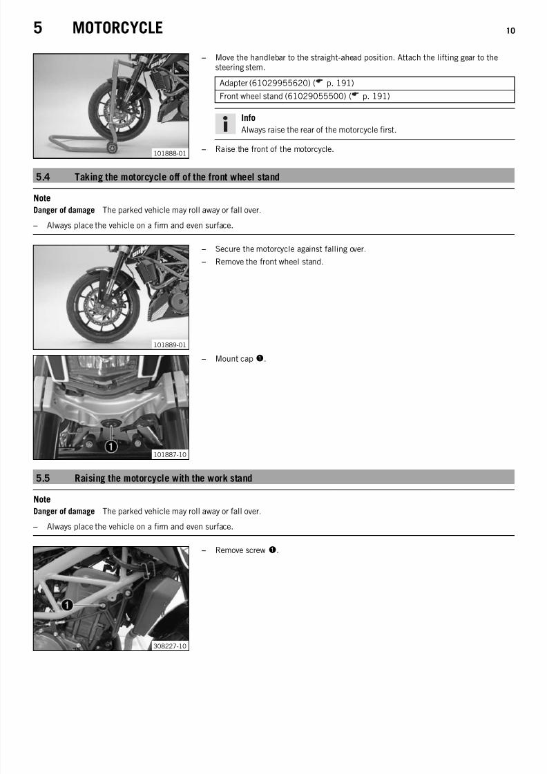
101888-01
– Move the handlebar to the straight-ahead position. Attach the lifting gear to thesteering stem.
Adapter (61029955620) ( p. 191)
Front wheel stand (61029055500) ( p. 191)
Info
Always raise the rear of the motorcycle first.
– Raise the front of the motorcycle.
5.4 Taking the motorcycle off of the front wheel stand
Note
Danger of damage The parked vehicle may roll away or fall over.
– Always place the vehicle on a firm and even surface.
101889-01
– Secure the motorcycle against falling over.
– Remove the front wheel stand.
101887-10
– Mount cap1.
5.5 Raising the motorcycle with the work stand
Note
Danger of damage The parked vehicle may roll away or fall over.
– Always place the vehicle on a firm and even surface.
308227-10
– Remove screw1.

7/21/2019 Duke 390 Repair Manual (Full Version - 204pages)
http://slidepdf.com/reader/full/duke-390-repair-manual-full-version-204pages 13/204
5 MOTORCYCLE 11
308228-10
– Mount special tool2 on the right side of the vehicle.
Work stand (62529055000) ( p. 192)
308229-10
– Remove screw3.
308230-10
– Mount special tool2 on the left side of the vehicle.
Work stand (62529055000) ( p. 192)
308231-10
– Position the motorcycle upright, align the special tool and raise the motorcycle.
5.6 Removing the motorcycle from the work stand
Note
Danger of damage
The parked vehicle may roll away or fall over. – Always place the vehicle on a firm and even surface.
308231-11
– Secure the motorcycle against falling over.
– Remove special tool1.

7/21/2019 Duke 390 Repair Manual (Full Version - 204pages)
http://slidepdf.com/reader/full/duke-390-repair-manual-full-version-204pages 14/204
5 MOTORCYCLE 12
308232-10
– Mount and tighten screws23.
Guideline
Screw, engine bearer on frame M8 30 Nm(22.1 lbf ft)
5.7 Starting
Danger
Danger of poisoning Exhaust gases are toxic and inhaling them may result in unconsciousness and/or death.
– When running the engine, always make sure there is sufficient ventilation, and do not start or run the engine in an enclosedspace without an effective exhaust extraction system.
Caution
Danger of accidents If the vehicle is operated with a discharged battery or without a battery, electronic components and safety
equipment may be damaged.
– Never operate the vehicle with a discharged battery or without a battery.
Note
Engine failure Unfiltered intake air has a negative effect on the service life of the engine.
– Never ride the vehicle without an air filter since dust and dirt can get into the engine and result in increased wear.
Note
Engine failure High engine speeds in cold engines have a negative effect on the service life of the engine.
– Always warm up the engine at low engine speeds.
B00782-10
– Sit on the vehicle, take the weight off of the side stand, and move up all the way.
– Turn the emergency OFF switch to the position .
– Switch on the ignition by turning the ignition key to the position .
After you switch on the ignition, you can hear the fuel pump working for abouttwo seconds. The function check of the combination instrument is run at thesame time.
– Shift gear to neutral.
The green idling speed indicator lamp N lights up.
The ABS warning lamp lights up and goes back out after starting off.
– Press the electric starter button .
Info
Do not press the electric starter button until the combination instrumentfunction check is finished.When starting, DO NOT open the throttle. If you open the throttle during thestarting procedure, fuel is not injected by the engine management systemand the engine cannot start.Press the starter for a maximum of 5 seconds. Wait for a least 5 secondsbefore trying again.This motorcycle is equipped with a safety starting system. You can only startthe engine if the transmission is in neutral or if the clutch is pulled when agear is engaged. If the side stand is folded out and you shift into gear andrelease the clutch, the engine stops.

7/21/2019 Duke 390 Repair Manual (Full Version - 204pages)
http://slidepdf.com/reader/full/duke-390-repair-manual-full-version-204pages 15/204
5 MOTORCYCLE 13
401685-15
Switching off ABS
KTM recommends riding with ABS at all times. However, situations may arise inwhich ABS is not advantageous.
Condition
Vehicle stationary, engine running.
– Press the1 button for 3 – 5 seconds.
The ABS warning lamp starts flashing; ABS is deactivated.
5.8 Starting the motorcycle to make checks
Danger
Danger of poisoning Exhaust gases are toxic and inhaling them may result in unconsciousness and/or death.
– When running the engine, always make sure there is sufficient ventilation, and do not start or run the engine in an enclosedspace without an effective exhaust extraction system.
Info
Press the starter for a maximum of 5 seconds. Wait for a least 5 seconds before trying again.
B00782-10
– Turn the emergency OFF switch to the position .
– Shift gear to neutral.
– Switch on the ignition by turning the ignition key to the position .
– Press the electric starter button .
Info
Do not open the throttle.

7/21/2019 Duke 390 Repair Manual (Full Version - 204pages)
http://slidepdf.com/reader/full/duke-390-repair-manual-full-version-204pages 16/204
6 FORK, TRIPLE CLAMP 14
6.1 Cleaning the dust boots of the fork legs
308233-10
– Push dust boot1 of both fork legs downwards.
Info
The dust boots should remove dust and coarse dirt particles from the forktubes. Over time, dirt can penetrate behind the dust boots. If this dirt is notremoved, the oil seals behind can start to leak.
Warning
Danger of accidents Reduced braking efficiency due to oil or grease on thebrake discs.
– Always keep the brake discs free of oil and grease, and clean them withbrake cleaner when necessary.
– Clean and oil the dust boots and inside fork tube of both fork legs.
Universal oil spray ( p. 188)
– Press the dust boots back into their normal position.
– Remove excess oil.
6.2 Removing fork legs
Preparatory work
– Raise the motorcycle with the work stand. ( p. 10)
– Tie the rear of the vehicle down.
– Dismount the front fender. ( p. 48)
308235-10
Main work
– Remove screw1.
– Remove the cable binder.
– Pull off the ABS sensor and hang it to one side.
308236-10
– Remove screws 2.
– Press back the brake linings with a light lateral tilting of the brake caliper on thebrake disc. Pull the brake caliper carefully back from the brake disc and hang it toone side.
Info
Do not pull the hand brake lever when the brake caliper has been removed.
308237-10
– Loosen screws3 and screw4.
– Unscrew screw3 about six turns and press your hand on the screw to push thewheel spindle out of the axle clamp. Remove screw 3.
Warning
Danger of accidents Reduced braking effect caused by damaged brakediscs.
– Always lay the wheel down in such a way that the brake discs are notdamaged.
– Holding the front wheel, withdraw the wheel spindle. Take the front wheel out of
the fork.

7/21/2019 Duke 390 Repair Manual (Full Version - 204pages)
http://slidepdf.com/reader/full/duke-390-repair-manual-full-version-204pages 17/204
6 FORK, TRIPLE CLAMP 15
308238-10
– Loosen screws5. Remove the fork legs from the bottom.
6.3 Installing the fork legs
Warning
Danger of accidents Modifications to the suspension settings can seriously alter the vehicle's ride behavior.
– Following modifications, ride slowly at first to get the feel of the new ride behavior.
308239-10
Main work
– Push the fork legs into the triple clamps.
– Align the fork legs in the required position using the fork rings.
308238-11
– Tighten screws1.
Guideline
Screw, top triple clamp M8 11 Nm (8.1 lbf ft)
– Tighten screws2.
Guideline
Screw, bottom triple clamp M8 15 Nm(11.1 lbf ft)
308240-10
– Check the wheel bearing for damage and wear.
» If the wheel bearing is damaged or worn:
– Change the wheel bearing.
– Clean and grease the shaft seal rings3 and contact surfaces A of the spacers.
Long-life grease ( p. 187)
308237-11
– Clean screw4 and the wheel spindle.
– Lift the front wheel into the fork, position it, and insert the wheel spindle.
– Mount and tighten screw4.
Guideline
Screw, front wheel spindle M8 30 Nm(22.1 lbf ft)

7/21/2019 Duke 390 Repair Manual (Full Version - 204pages)
http://slidepdf.com/reader/full/duke-390-repair-manual-full-version-204pages 18/204

7/21/2019 Duke 390 Repair Manual (Full Version - 204pages)
http://slidepdf.com/reader/full/duke-390-repair-manual-full-version-204pages 19/204
6 FORK, TRIPLE CLAMP 17
201506-10
– Loosen the screw cap1.
Info
The screw cap cannot be removed yet.
201507-10
– Empty the fork oil.
201508-10
– Release the fork leg and clamp it with the fork stub.
Info
Use soft jaws.
201509-10
– Push the outer tube downward.
– Hold screw cap1. Loosen nut 2. Remove the screw cap.
201510-10
– Detach the outer tube from the inner tube.
Info
Place a container underneath to catch any oil that may run out.
201511-10
– Unclamp the inner tube. Drain the oil.

7/21/2019 Duke 390 Repair Manual (Full Version - 204pages)
http://slidepdf.com/reader/full/duke-390-repair-manual-full-version-204pages 20/204
6 FORK, TRIPLE CLAMP 18
201512-10
– Clamp the outer tube in the area of the lower triple clamp.
Clamping stand (T612S) ( p. 197)
– Remove dust boot3.
201513-10
– Remove lock ring4.
Info
The lock ring has a beveled end where a screwdriver can be applied.
201514-10
– Remove seal ring5. Remove support ring 6.
201515-10
– Unclamp the outer tube.
– Heat up the outer tube in the area of sliding bushing7.
Guideline
50 °C (122 °F)
– Strike the lower edge of the outer fork tube on a wooden board.
Sliding bushing7 must fall out of its seat.
6.5 Checking the fork legs
Condition
The fork legs have been disassembled.
201516-10
– Check the inner tube and the axle clamp for damage.» If damage is found:
– Change the fork leg.

7/21/2019 Duke 390 Repair Manual (Full Version - 204pages)
http://slidepdf.com/reader/full/duke-390-repair-manual-full-version-204pages 21/204
6 FORK, TRIPLE CLAMP 19
200684-10
– Measure the outside diameter of the inner tube in several places.
External diameter of inner tube 42.975… 43.005 mm (1.69193…1.69311 in)
» If the measured value is less than the specified value:
– Change the fork leg.
200685-10
– Measure the run-out of the inner tube.
Run-out of inner tube ≤ 0.20 mm (≤ 0.0079 in)
» If the measured value is greater than the specified value:
– Change the fork leg.
200632-10
– Check the outer tube for damage.
» If damage is found:
– Change the fork leg.
201517-10
– Check the surface of the sliding bushings.
» If the dark layerA is worn off:
– Change the fork leg.
6.6 Assembling the fork legs
Info
These operations are the same on both fork legs.
Preparatory work
– Check the fork legs. ( p. 18)
202092-10
Main work
– Clamp in the inner tube with the axle clamp.
Guideline
Use soft jaws.
– Grease and slide on dust boot1.
Lubricant (T511) ( p. 187)
InfoAlways change the dust boot, lock ring, seal ring, and support ring.Install the dust boot with the sealing lip and spring expander facing down-ward.

7/21/2019 Duke 390 Repair Manual (Full Version - 204pages)
http://slidepdf.com/reader/full/duke-390-repair-manual-full-version-204pages 22/204
6 FORK, TRIPLE CLAMP 20
– Slide on lock ring2.
– Grease and slide on seal ring3.
Lubricant (T511) ( p. 187)
Info
Mount with the sealing lip facing down and the open side facing up.
– Slide on support ring4.
– Sand the edges of sliding bushing5 with 600-grit sandpaper, then clean andgrease.
Fork oil (SAE 4) (48601166S1) ( p. 186)
– Slide on sliding bushing5.
202093-10
– Warm up the outer tube in the lower sliding bushing areaA.
Guideline
50 °C (122 °F)
– Slide the outer tube onto the inner tube.
– Hold the sliding bushing with the longer shoulder of the special tool.
Mounting tool (T528S) ( p. 197)
– Push the sliding bushing all the way into the outer tube.
202094-10
– Position the support ring.
– Hold the seal ring with the shorter shoulder of the special tool.
Mounting tool (T528S) ( p. 197)
– Push the seal ring and support ring all the way into the outer tube.
202095-10
– Mount lock ring2.
Info
The lock ring must engage audibly.
202096-10
– Install dust boot1.

7/21/2019 Duke 390 Repair Manual (Full Version - 204pages)
http://slidepdf.com/reader/full/duke-390-repair-manual-full-version-204pages 23/204
6 FORK, TRIPLE CLAMP 21
202097-10
– Mount screw cap6 onto the piston rod.
Info
Nut7 must be turned all the way down.
– Hold the screw cap and tighten the nut.
Guideline
Nut, piston rod on screw cap M12x1 30 Nm(22.1 lbf ft)
201523-10
– Fill it with fork oil.
Fork oil 450 ml(15.21 fl. oz.)
Fork oil (SAE 4) (48601166S1)( p. 186)
Info
If it should be impossible to add the full quantity of oil, close the screw capof the outer tube, unclamp the fork and bounce a number of times. Thenadd the remaining quantity.
201522-10
– Push the outer tube upward.
– Mount screw cap6.
– Unclamp the fork leg in the area of the lower triple clamp.
Clamping stand (T612S) ( p. 197)
– Tighten the screw cap.
Guideline
Screw cap on outer tube M47x1.5 30 Nm(22.1 lbf ft)
6.7 Removing the lower triple clamp
Preparatory work
– Raise the motorcycle with the work stand. ( p. 10)
– Tie the rear of the vehicle down.
– Dismount the front fender. ( p. 48)
– Remove the fork legs. ( p. 14)
308242-10
Main work
– Remove expanding rivets1.
308243-10
– Remove screws 2.
– Lift the headlight mask slightly and swing forward.

7/21/2019 Duke 390 Repair Manual (Full Version - 204pages)
http://slidepdf.com/reader/full/duke-390-repair-manual-full-version-204pages 24/204
6 FORK, TRIPLE CLAMP 22
308244-10
– Detach connectors 3 and4.
308245-10
– Detach connectors 5 and6.
308246-10
– Remove the connector holder.
– Disconnect connector 7.
308247-10
– Remove the combination instrument.
308248-10
– Remove screws 8.
– Remove the headlight mask.
308249-10
– Remove screw9.

7/21/2019 Duke 390 Repair Manual (Full Version - 204pages)
http://slidepdf.com/reader/full/duke-390-repair-manual-full-version-204pages 25/204
6 FORK, TRIPLE CLAMP 23
308251-10
– Remove the upper triple clamp with the handlebar and set aside.
Info
Protect the vehicle and its attachments from damage by covering them.
308252-10
– Expose the cable.
308253-10
– Remove nut bk.
Castle nut wrench; ½" drive (90129050100) ( p. 195)
308254-10
– Remove washer bl.
– Remove steering head bearing bm.
– Remove the lower triple clamp with the steering stem.
6.8 Installing the lower triple clamp
308254-11
Main work
– Clean the bearing and sealing elements, check for damage, and grease.
High viscosity grease ( p. 187)
– Insert the lower triple clamp with the steering stem.
– Mount the upper steering head bearing1.
– Mount washer2 with the cut-out facing downward.
308253-11
Alternative 1
A new steering head bearing is used.
– Mount and tighten nut 3.

7/21/2019 Duke 390 Repair Manual (Full Version - 204pages)
http://slidepdf.com/reader/full/duke-390-repair-manual-full-version-204pages 26/204
6 FORK, TRIPLE CLAMP 24
Guideline
Nut, steering head M30x1 Step 150 Nm(36.9 lbf ft)2nd stage(loosen, counter-clockwise)2 turnsStep 35 Nm (3.7 lbf ft)
Castle nut wrench; ½" drive (90129050100) ( p. 195)
Alternative 2
The steering head bearing is used again.
– Mount and tighten nut 3.
Guideline
Nut, steering head M30x1 5 Nm (3.7 lbf ft)
Castle nut wrench; ½" drive (90129050000) ( p. 195)
308252-10
– Secure the cable in the bracket.
308251-10
– Position the upper triple clamp with the handlebar.
308250-10
– Mount screw4 with the washer but do not tighten it yet.
Guideline
Screw, top steering head M16x1.5 52 Nm(38.4 lbf ft)
Holding lugsA
reach into the drilled holes.
308248-11
– Position the headlight mask.
– Mount and tighten screw5.
Guideline
Screw, headlight mask M6 11 Nm (8.1 lbf ft)

7/21/2019 Duke 390 Repair Manual (Full Version - 204pages)
http://slidepdf.com/reader/full/duke-390-repair-manual-full-version-204pages 27/204
6 FORK, TRIPLE CLAMP 25
308246-11
– Position the combination instrument.
– Plug in connector 6.
– Mount the connector holder7.
308245-11
– Plug in connectors 8 and9.
308244-11
– Plug in connectors bk and bl.
308243-11
– Fold the headlight mask up.
– Mount and tighten screws bm.
Guideline
Screw, headlight mask M6 11 Nm (8.1 lbf ft)
308242-11
– Mount expanding rivets bn on both sides.
– Install the fork legs. ( p. 15)
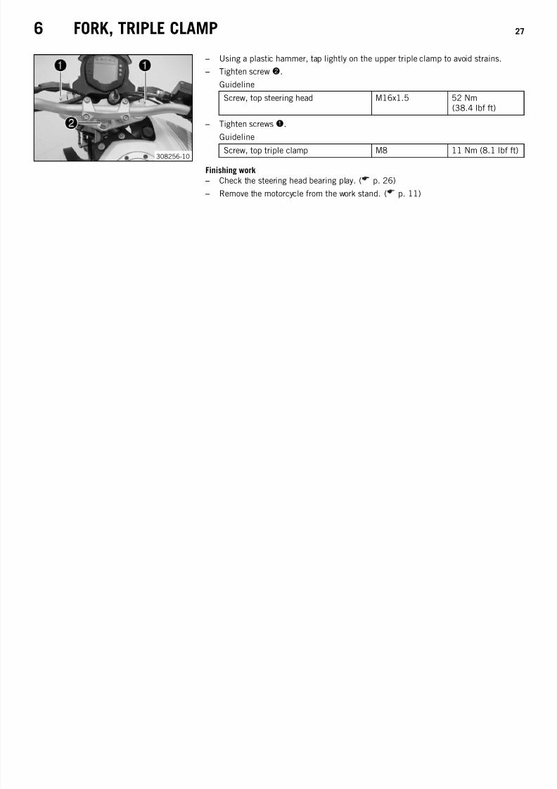
308255-10
– Loosen screws bo.
– Using a plastic hammer, tap lightly on the upper triple clamp to avoid strains.
– Tighten screw4.
Guideline
Screw, top steering head M16x1.5 52 Nm(38.4 lbf ft)
– Tighten screws bo.
Guideline
Screw, top triple clamp M8 11 Nm (8.1 lbf ft)

7/21/2019 Duke 390 Repair Manual (Full Version - 204pages)
http://slidepdf.com/reader/full/duke-390-repair-manual-full-version-204pages 28/204
6 FORK, TRIPLE CLAMP 26
Finishing work
– Check that the wiring harness, throttle cables, and brake line have the necessaryfreedom of movement and are correctly routed.
– Check the steering head bearing play. ( p. 26)
– Remove the motorcycle from the work stand. ( p. 11)
6.9 Checking the steering head bearing play
Warning
Danger of accidents Unstable vehicle handling from incorrect steering head bearing play.
– Adjust the steering head bearing play without delay.
Info
If the bike is ridden with play in the steering head bearing, the bearing and the bearing seats in the frame can become dam-aged with time.
Preparatory work
– Raise the motorcycle with the work stand. ( p. 10)
400738-11
Main work – Move the handlebar to the straight-ahead position. Move the fork legs to and fro in
the direction of travel.
No play should be noticeable in the steering head bearing.
» If there is noticeable play present:
– Adjust the play of the steering head bearing. ( p. 26)
– Move the handlebar to and fro over the entire steering range.
The handlebar must be able to move easily over the entire steering range. Noresting locations should be noticeable.
» If click positions are noticeable:
–
Adjust the play of the steering head bearing. ( p. 26) – Check the steering head bearing and change if necessary.
Finishing work
– Remove the motorcycle from the work stand. ( p. 11)
6.10 Adjusting the steering head bearing play
Preparatory work
– Raise the motorcycle with the work stand. ( p. 10)
308256-10
Main work
– Loosen screws1.
– Loosen screw2.
308257-10
– Tighten nut 3 with the special tool until there is no play in the steering head bear-ing.
Key for steering head bearing (90129051000) ( p. 195)
7/21/2019 Duke 390 Repair Manual (Full Version - 204pages)
http://slidepdf.com/reader/full/duke-390-repair-manual-full-version-204pages 29/204
6 FORK, TRIPLE CLAMP 27
308256-10
– Using a plastic hammer, tap lightly on the upper triple clamp to avoid strains.
– Tighten screw2.
Guideline
Screw, top steering head M16x1.5 52 Nm(38.4 lbf ft)
– Tighten screws1.
GuidelineScrew, top triple clamp M8 11 Nm (8.1 lbf ft)
Finishing work
– Check the steering head bearing play. ( p. 26)
– Remove the motorcycle from the work stand. ( p. 11)

7/21/2019 Duke 390 Repair Manual (Full Version - 204pages)
http://slidepdf.com/reader/full/duke-390-repair-manual-full-version-204pages 30/204
7 HANDLEBAR, CONTROLS 28
7.1 Checking the play in the throttle cable
400192-10
– Check the throttle grip for smooth operation.
– Move the handlebar to the straight-ahead position. Move the throttle grip back-wards and forwards to ascertain the play in the throttle cable.
Throttle cable play 3… 5 mm (0.12… 0.2 in)
» If the throttle cable play does not meet specifications: – Adjust the play in the throttle cable. ( p. 28)
Danger
Danger of poisoning Exhaust gases are toxic and inhaling them may resultin unconsciousness and/or death.
– When running the engine, always make sure there is sufficient ventila-tion, and do not start or run the engine in an enclosed space without aneffective exhaust extraction system.
– Start the engine and let it run idle. Move the handlebar to and fro over the entiresteering range.
The idle speed must not change.
» If the idle speed changes:
– Check the throttle cable routing.
7.2 Adjusting the play in the throttle cable
B00728-10
– Move the handlebar to the straight-ahead position.
– Push back sleeve1.
– Loosen lock nut 2.
– Adjust the play in the throttle cable by turning adjusting screw3.
Guideline
Throttle cable play 3… 5 mm (0.12… 0.2 in)
– Tighten lock nut 2. – Slide on sleeve1.
7.3 Checking the clutch lever play
101914-10
– Check the clutch lever for smooth operation.
– Move the handlebar to the straight-ahead position. Lightly pull the clutch lever andascertain the clutch lever playA.
Clutch lever play 1… 3 mm (0.04… 0.12 in)
» If the clutch lever play does not meet specifications:
– Adjust the clutch cable play. ( p. 29)
Note
Clutch damage If there is no play on the clutch lever, the clutch will begin to slip.
– When operating the motorcycle, always check the clutch lever play.
– Move the handlebar to and fro over the entire steering range.
The clutch lever play must not change.
» If the clutch lever play changes:
– Check the routing of the clutch cable.

7/21/2019 Duke 390 Repair Manual (Full Version - 204pages)
http://slidepdf.com/reader/full/duke-390-repair-manual-full-version-204pages 31/204
7 HANDLEBAR, CONTROLS 29
7.4 Adjusting the clutch cable play
101915-10
– Move the handlebar to the straight-ahead position.
– Push back sleeve1.
– Loosen lock nut 2.
– Adjust the play in the clutch levelA by turning adjusting screw3.
Guideline
Clutch lever play 1… 3 mm (0.04… 0.12 in)
– Tighten lock nut 2.
– Slide on sleeve1.

7/21/2019 Duke 390 Repair Manual (Full Version - 204pages)
http://slidepdf.com/reader/full/duke-390-repair-manual-full-version-204pages 32/204
8 SHOCK ABSORBER, SWINGARM 30
8.1 Adjusting the spring preload of the shock absorber
Warning
Danger of accidents Modifications to the suspension settings can seriously alter the vehicle's ride behavior.
– Following modifications, ride slowly at first to get the feel of the new ride behavior.
Info
The spring preload defines the initial situation of the spring process on the shock absorber.The best spring preload setting is achieved when it is set for the weight of the rider and that of any baggage and a passenger,thus ensuring an ideal compromise between maneuverability and stability.
101886-10
– Adjust the spring preload by turning adjusting ring1.
Guideline
Spring preload
Standard 3 clicks
Full payload 10 clicks
Hook wrench (T106S) ( p. 196)
Info
The spring preload can be set to 10 different positions.
8.2 Removing the shock absorber
Preparatory work
– Raise the motorcycle with the work stand. ( p. 10)
308258-10
Main work
– Remove screw1.
Info
Protect the link fork and attachments from damage.Ensure that the chain and brake line are not damaged.
308259-10
– Remove fitting2.
– Lift the link fork and take out the shock absorber3 toward the rear.
8.3 Installing the shock absorber
308259-11
Main work
– Lift the link fork and position shock absorber1.
– Mount fitting2 but do not tighten yet.
Guideline
Fitting, bottom shock absorber M10x1.25 45 Nm(33.2 lbf ft)

7/21/2019 Duke 390 Repair Manual (Full Version - 204pages)
http://slidepdf.com/reader/full/duke-390-repair-manual-full-version-204pages 33/204
8 SHOCK ABSORBER, SWINGARM 31
308258-11
– Lift the link fork.
– Mount and tighten screw3.
Guideline
Screw, top shock absorber M10x1.25 50 Nm(36.9 lbf ft)
– Tighten fitting2.
GuidelineFitting, bottom shock absorber M10x1.25 45 Nm
(33.2 lbf ft)
Finishing work
– Remove the motorcycle from the work stand. ( p. 11)
8.4 Removing the spring
Condition
The shock absorber has been removed.
201698-10
– Clamp the shock absorber in the vise using soft jaws for protection.
– Note the position of the spring preload.
– Loosen adjusting ringA using the special tool.Hook wrench (T106S) ( p. 196)
201697-10
– Clamp the shock absorber into the special tool.
Spring compressor (T14050S) ( p. 196)
Info
Use the ring of the special tool with the smallest possible inside diameter. Itmust be pressed directly onto the spring.
– Compress the spring.
– Remove spring retainer1.
– Release the spring. Remove the shock absorber from the special tool.
– Remove the spring.
8.5 Installing the spring
201697-10
– Mount the spring.
The tight coil of the spring is at the bottom.
– Clamp the shock absorber into the special tool.
Spring compressor (T14050S) ( p. 196)
Info
Use the ring of the special tool with the smallest possible inside diameter. Itmust be pressed directly onto the spring.
– Mount spring retainer1.
The open end is opposite the spring end.
– Release the spring. Remove the shock absorber from the special tool.
– Clamp the shock absorber in the vise using soft jaws for protection.

7/21/2019 Duke 390 Repair Manual (Full Version - 204pages)
http://slidepdf.com/reader/full/duke-390-repair-manual-full-version-204pages 34/204
8 SHOCK ABSORBER, SWINGARM 32
201698-10
Alternative 1
– Tension the spring to the prescribed position by turning the adjusting ring.
Guideline
Spring preload
Standard 3 clicks
Full payload 10 clicks
Hook wrench (T106S) ( p. 196)
Alternative 2
Warning
Danger of accidents Modifications to the suspension settings can seri-ously alter the vehicle's ride behavior.
– Extreme modifications to the adjustment of the suspension compo-nents can cause a serious deterioration in the handling characteris-tics and overload some components.
– Only make adjustments within the recommended range.
– After making adjustments, ride slowly at first to get the feel of thenew ride behavior.
– Tension the spring to the position measured during dismantling by turning theadjusting ring.

7/21/2019 Duke 390 Repair Manual (Full Version - 204pages)
http://slidepdf.com/reader/full/duke-390-repair-manual-full-version-204pages 35/204
9 EXHAUST 33
9.1 Removing the exhaust manifold
Warning
Danger of burns The exhaust system gets very hot when the vehicle is driven.
– Allow the exhaust system to cool down. Do not touch hot components.
308293-10
– Remove nuts1 with the washers. – Swing the radiator forward slightly.
308294-10
– Remove the cable binder, expose the connector2 of the lambda probe, anddetach.
308295-10
– Loosen exhaust clamp3.
308296-10
– Remove the nuts4.
308297-10
– Remove the exhaust manifold toward the front.

7/21/2019 Duke 390 Repair Manual (Full Version - 204pages)
http://slidepdf.com/reader/full/duke-390-repair-manual-full-version-204pages 36/204
9 EXHAUST 34
9.2 Installing the exhaust manifold
308297-10
– Position the exhaust manifold.
308296-11
– Mount nuts1 but do not tighten them yet.
Guideline
Nut, exhaust flange M8 22 Nm(16.2 lbf ft)
308295-11
– Position and tighten exhaust clamp2.
Guideline
Exhaust clamp - 10 Nm (7.4 lbf ft)
– Tighten nuts1.
Guideline
Nut, exhaust flange M8 22 Nm(16.2 lbf ft)
308294-11
– Plug in connector 3. – Secure the connector with a cable binder.
308293-11
– Position the radiator.
– Mount and tighten nuts4 with the washers.
GuidelineNut, radiator M6 5 Nm (3.7 lbf ft)

7/21/2019 Duke 390 Repair Manual (Full Version - 204pages)
http://slidepdf.com/reader/full/duke-390-repair-manual-full-version-204pages 37/204
9 EXHAUST 35
9.3 Removing the main silencer
Preparatory work
– Remove the exhaust manifold. ( p. 33)
308299-10
Main work
– Remove screw1 with washers.
308300-10
– Remove screw2 with the sleeve.
– Hang the brake fluid reservoir to the side.
Info
Ensure that brake fluid does not escape.
308301-10
– Remove screw2 with washers.
308302-10
– Remove screw4.
Info
Do not misplace the sleeves.
308303-10
–
Take off the main silencer toward the bottom.

7/21/2019 Duke 390 Repair Manual (Full Version - 204pages)
http://slidepdf.com/reader/full/duke-390-repair-manual-full-version-204pages 38/204

7/21/2019 Duke 390 Repair Manual (Full Version - 204pages)
http://slidepdf.com/reader/full/duke-390-repair-manual-full-version-204pages 39/204
10 AIR FILTER 37
10.1 Removing the air filter
Note
Engine failure Unfiltered intake air has a negative effect on the service life of the engine.
– Never ride the vehicle without an air filter since dust and dirt can get into the engine and result in increased wear.
Preparatory work – Remove the passenger seat. ( p. 39)
– Remove the seat. ( p. 38)
308260-10
Main work
– Remove screws 1.
– Pull the air filter box lid forward and move to the side.
308261-10
– Remove air filter2.
– Clean the air filter box.
10.2 Installing the air filter
308261-11
Main work
– Position air filter1.
308260-11
– Mount air filter box lid.
InfoMake sure the air filter box lid is seated correctly.
– Mount and tighten screws2.
Guideline
Screw, air filter box M6 6 Nm (4.4 lbf ft)
Finishing work
– Mount the seat. ( p. 39)
– Mount the passenger seat. ( p. 39)

7/21/2019 Duke 390 Repair Manual (Full Version - 204pages)
http://slidepdf.com/reader/full/duke-390-repair-manual-full-version-204pages 40/204
11 FUEL TANK, SEAT, TRIM 38
11.1 Opening the filler cap
Danger
Fire hazard Fuel is highly flammable.
– Never refuel the vehicle near open flames or burning cigarettes, and always switch off the engine first. Be careful that nofuel is spilt, especially on hot vehicle components. Clean up spilt fuel immediately.
– The fuel in the fuel tank expands when warm and may emerge if overfilled. Follow the instructions on refueling.Warning
Danger of poisoning Fuel is poisonous and a health hazard.
– Fuel must not come into contact with the skin, eyes, or clothing. Do not breathe in the fuel vapors. If contact occurs withthe eyes, rinse with water immediately and contact a physician. Immediately clean contaminated areas on the skin withsoap and water. If fuel is swallowed, contact a physician immediately. Change clothing that is contaminated with fuel.Store fuel properly in a suitable canister and keep away from children.
Warning
Environmental hazard Improper handling of fuel is a danger to the environment.
– Do not allow fuel to get into the ground water, the ground, or the sewage system.
B00710-10
– Lift the cover1 of the filler cap and insert the ignition key in the lock.
Note
Danger of damage Ignition key breakage.
– To take pressure off of the ignition key, push down on the filler cap. Damagedignition keys must be replaced.
– Turn the ignition key 90° clockwise.
– Open the filler cap.
– Remove the ignition key.
11.2 Closing the filler cap
B00711-01
Warning
Fire hazard Fuel is highly flammable, poisonous and harmful to yourhealth.
– After closing the filler cap, ensure that it is locked properly. Changeclothing that has been contaminated with fuel. Immediately clean con-taminated areas on the skin with soap and water.
– Close the filler cap.
– Push down the filler cap until the lock engages.
11.3 Removing the seat
Preparatory work – Remove the passenger seat. ( p. 39)
101891-10
Main work
– Remove screws 1.
– Raise the rear of the seat, pull it towards the rear, and remove it upwards.

7/21/2019 Duke 390 Repair Manual (Full Version - 204pages)
http://slidepdf.com/reader/full/duke-390-repair-manual-full-version-204pages 41/204
11 FUEL TANK, SEAT, TRIM 39
11.4 Mounting the seat
101892-10
Main work
– Attach seat recessesA at screws 1 and lower at the rear.
– Mount and tighten screws2.
Guideline
Screw, seat M6 11 Nm (8.1 lbf ft)
Finishing work
– Mount the passenger seat. ( p. 39)
11.5 Removing the passenger seat
101881-10
– Insert the ignition key in seat lock1 and turn it clockwise.
– Raise the rear of the seat, push it towards the rear, and remove it upwards.
– Remove the ignition key from the seat lock.
11.6 Mounting the passenger seat
101890-10
– Attach hooks1 on the passenger seat to brackets 2 on the subframe, and lower itat the rear while pushing forward.
– Press down the passenger seat until it clicks into place.
Warning
Danger of accidents The passenger seat can come loose from the anchoringif it is not mounted correctly.
– After mounting the passenger seat, check that it is locked correctly bypulling up.
– Finally, check that the passenger seat is correctly mounted.
11.7 Removing the fuel tank cover
Danger
Fire hazard Fuel is highly flammable.
– Never refuel the vehicle near open flames or burning cigarettes, and always switch off the engine first. Be careful that nofuel is spilt, especially on hot vehicle components. Clean up spilt fuel immediately.
– The fuel in the fuel tank expands when warm and may emerge if overfilled. Follow the instructions on refueling.

7/21/2019 Duke 390 Repair Manual (Full Version - 204pages)
http://slidepdf.com/reader/full/duke-390-repair-manual-full-version-204pages 42/204
11 FUEL TANK, SEAT, TRIM 40
Warning
Danger of poisoning Fuel is poisonous and a health hazard.
– Fuel must not come into contact with the skin, eyes, or clothing. Do not breathe in the fuel vapors. If contact occurs withthe eyes, rinse with water immediately and contact a physician. Immediately clean contaminated areas on the skin withsoap and water. If fuel is swallowed, contact a physician immediately. Change clothing that is contaminated with fuel.Store fuel properly in a suitable canister and keep away from children.
WarningEnvironmental hazard Improper handling of fuel is a danger to the environment.
– Do not allow fuel to get into the ground water, the ground, or the sewage system.
Preparatory work
– Remove the passenger seat. ( p. 39)
– Remove the seat. ( p. 38)
304820-10
Create the tool (special screw):
Three conventional screws are required.
– Cut off screw1 to length A.
Guideline
Screw M5x50Length A 40 mm (1.57 in)
– Cut a slot into the top end of the screw.
308273-10
– Remove screw2.
Info
Always remove the screws individually and replace them with a specialscrew to avoid distorting the fuel tank.
– Mount and tighten special screw1.
308274-10
– Remove screw2.
– Mount and tighten another special screw1.
308275-10
– Remove screw2.
– Mount and tighten another special screw1.
– Open the filler cap. ( p. 38)

7/21/2019 Duke 390 Repair Manual (Full Version - 204pages)
http://slidepdf.com/reader/full/duke-390-repair-manual-full-version-204pages 43/204
11 FUEL TANK, SEAT, TRIM 41
308276-10
– Remove filler cap3.
308277-10
– Remove screws 4 with the washers.
308278-10
– Remove screws 5.
– Remove screws 6.
308279-10
– Remove cap7 from the compensating tank.
308280-10
– Remove screws 8.
308281-10
– Lift the fuel tank cover.
– Detach the side covers on both sides.

7/21/2019 Duke 390 Repair Manual (Full Version - 204pages)
http://slidepdf.com/reader/full/duke-390-repair-manual-full-version-204pages 44/204
11 FUEL TANK, SEAT, TRIM 42
308282-10
– Push back hose clamp9.
– Pull off the vent hose.
– Remove the fuel tank cover.
308283-10
– Close the fuel tank with a suitable plug.
11.8 Installing the fuel tank cover
Danger
Fire hazard Fuel is highly flammable.
– Never refuel the vehicle near open flames or burning cigarettes, and always switch off the engine first. Be careful that nofuel is spilt, especially on hot vehicle components. Clean up spilt fuel immediately.
– The fuel in the fuel tank expands when warm and may emerge if overfilled. Follow the instructions on refueling.
Warning
Danger of poisoning Fuel is poisonous and a health hazard.
– Fuel must not come into contact with the skin, eyes, or clothing. Do not breathe in the fuel vapors. If contact occurs withthe eyes, rinse with water immediately and contact a physician. Immediately clean contaminated areas on the skin withsoap and water. If fuel is swallowed, contact a physician immediately. Change clothing that is contaminated with fuel.Store fuel properly in a suitable canister and keep away from children.
Warning
Environmental hazard Improper handling of fuel is a danger to the environment.
– Do not allow fuel to get into the ground water, the ground, or the sewage system.
308283-10
Main work
– Remove the plug.
308282-11
– Mount the vent hose.
– Position hose clamp1.

7/21/2019 Duke 390 Repair Manual (Full Version - 204pages)
http://slidepdf.com/reader/full/duke-390-repair-manual-full-version-204pages 45/204

7/21/2019 Duke 390 Repair Manual (Full Version - 204pages)
http://slidepdf.com/reader/full/duke-390-repair-manual-full-version-204pages 46/204
11 FUEL TANK, SEAT, TRIM 44
308285-10
– Mount and tighten screws7 with the washer.
Guideline
Screw, fuel tank M6 11 Nm (8.1 lbf ft)
308278-11
– Mount and tighten screws8.
Guideline
Screw, fuel tank trim M5 5 Nm (3.7 lbf ft)
– Mount and tighten screws9.
Guideline
Screw, front seat fixing M6 5 Nm (3.7 lbf ft)
Finishing work
– Mount the seat. ( p. 39)
– Mount the passenger seat. ( p. 39)
11.9 Removing the fuel tank
Danger
Fire hazard Fuel is highly flammable.
– Never refuel the vehicle near open flames or burning cigarettes, and always switch off the engine first. Be careful that nofuel is spilt, especially on hot vehicle components. Clean up spilt fuel immediately.
– The fuel in the fuel tank expands when warm and may emerge if overfilled. Follow the instructions on refueling.
WarningDanger of poisoning Fuel is poisonous and a health hazard.
– Fuel must not come into contact with the skin, eyes, or clothing. Do not breathe in the fuel vapors. If contact occurs withthe eyes, rinse with water immediately and contact a physician. Immediately clean contaminated areas on the skin withsoap and water. If fuel is swallowed, contact a physician immediately. Change clothing that is contaminated with fuel.Store fuel properly in a suitable canister and keep away from children.
Warning
Environmental hazard Improper handling of fuel is a danger to the environment.
– Do not allow fuel to get into the ground water, the ground, or the sewage system.
Preparatory work
– Remove the passenger seat. ( p. 39) – Remove the seat. ( p. 38)
– Remove the fuel tank cover. ( p. 39)
308286-10
Main work
– Remove screw1.
– Hang the EFI control unit to one side.
Info
Protect the frame and attachments from damage.

7/21/2019 Duke 390 Repair Manual (Full Version - 204pages)
http://slidepdf.com/reader/full/duke-390-repair-manual-full-version-204pages 47/204
11 FUEL TANK, SEAT, TRIM 45
308287-10
– Remove screws 2.
308288-10
– Take off the holder3.
308289-10
– Detach connector 4.
308290-10
– Detach the fuel line with a suitable tool5.
308291-10
– Push back hose clamp6.
– Pull off the fuel line and remove the fuel tank.
11.10 Installing the fuel tank
Danger
Fire hazard Fuel is highly flammable.
– Never refuel the vehicle near open flames or burning cigarettes, and always switch off the engine first. Be careful that nofuel is spilt, especially on hot vehicle components. Clean up spilt fuel immediately.
– The fuel in the fuel tank expands when warm and may emerge if overfilled. Follow the instructions on refueling.

7/21/2019 Duke 390 Repair Manual (Full Version - 204pages)
http://slidepdf.com/reader/full/duke-390-repair-manual-full-version-204pages 48/204
11 FUEL TANK, SEAT, TRIM 46
Warning
Danger of poisoning Fuel is poisonous and a health hazard.
– Fuel must not come into contact with the skin, eyes, or clothing. Do not breathe in the fuel vapors. If contact occurs withthe eyes, rinse with water immediately and contact a physician. Immediately clean contaminated areas on the skin withsoap and water. If fuel is swallowed, contact a physician immediately. Change clothing that is contaminated with fuel.Store fuel properly in a suitable canister and keep away from children.
WarningEnvironmental hazard Improper handling of fuel is a danger to the environment.
– Do not allow fuel to get into the ground water, the ground, or the sewage system.
308291-11
Main work
– Connect the fuel line.
– Position hose clamp1.
308290-11
– Remove tool 2.
308289-11
–
Plug in connector3
.
308288-11
– Position the fuel tank.
– Position the holder4.
308287-11
– Mount and tighten screws5.
Guideline
Screw, fuel tank M6 11 Nm (8.1 lbf ft)

7/21/2019 Duke 390 Repair Manual (Full Version - 204pages)
http://slidepdf.com/reader/full/duke-390-repair-manual-full-version-204pages 49/204
11 FUEL TANK, SEAT, TRIM 47
308286-11
– Position the EFI control unit.
– Mount and tighten screws6.
Guideline
Screw, EFI control unit M4 4 Nm (3 lbf ft)
Finishing work
– Install the fuel tank cover. ( p. 42)
– Mount the seat. ( p. 39)
– Mount the passenger seat. ( p. 39)
11.11 Removing the front spoiler
101895-10
– Remove screws 1.
101896-10
– Remove screws 2.
– Take off the front spoiler.
11.12 Fitting front spoiler
101895-10
– Position the front spoiler. Mount screws1 but do not tighten yet.
101896-10
– Mount and tighten screws2.
Guideline
Remaining screws, chassis M6 10 Nm (7.4 lbf ft)
– Tighten screw1.
Guideline
Remaining screws, chassis M6 10 Nm (7.4 lbf ft)

7/21/2019 Duke 390 Repair Manual (Full Version - 204pages)
http://slidepdf.com/reader/full/duke-390-repair-manual-full-version-204pages 50/204
11 FUEL TANK, SEAT, TRIM 48
11.13 Dismounting the front fender
308234-10
– Remove screws 1. Remove the front fender.
11.14 Installing the front fender
308234-10
– Position the front fender. Mount and tighten screws1.
Guideline
Screw, front fender M6 11 Nm (8.1 lbf ft)
11.15 Checking the fuel pressure
Danger
Fire hazard Fuel is highly flammable.
– Never refuel the vehicle near open flames or burning cigarettes, and always switch off the engine first. Be careful that nofuel is spilt, especially on hot vehicle components. Clean up spilt fuel immediately.
–
The fuel in the fuel tank expands when warm and may emerge if overfilled. Follow the instructions on refueling.Warning
Danger of poisoning Fuel is poisonous and a health hazard.
– Fuel must not come into contact with the skin, eyes, or clothing. Do not breathe in the fuel vapors. If contact occurs withthe eyes, rinse with water immediately and contact a physician. Immediately clean contaminated areas on the skin withsoap and water. If fuel is swallowed, contact a physician immediately. Change clothing that is contaminated with fuel.Store fuel properly in a suitable canister and keep away from children.
Condition
The fuel tank is full.Ensure that the battery voltage does not drop below 12.5 V.The ignition is off.
The diagnostics tool is connected.
308292-10
– Detach the fuel line with a suitable tool.
– Push back hose clamp1 and pull off the fuel line.

7/21/2019 Duke 390 Repair Manual (Full Version - 204pages)
http://slidepdf.com/reader/full/duke-390-repair-manual-full-version-204pages 51/204
11 FUEL TANK, SEAT, TRIM 49
033
022400926-10
– Mount special tool2.
Pressure testing tool (61029094000) ( p. 191)
– Mount special tool3 with the nozzle code 0,45.
Testing hose (61029093000) ( p. 191)
– Position the hose end in a fuel can.
GuidelineMinimum size of fuel can 10 l (2.6 US gal)
– Switch the ignition on.
– Execute "Actuator test" > "Fuel pump relay function test".
400927-01
– Check the fuel pressure with the filler cap closed.
Fuel pressure
When the fuel pump is active 2.5… 2.9 bar (36… 42 psi)
» If the specification is not reached:
– Open the filler cap. ( p. 38)
– Check the tank air vent system.
400928-01
– Check the fuel pressure with the filler cap open.
Fuel pressure
When the fuel pump is active 2.5… 2.9 bar (36… 42 psi)
» If the specification is not reached:
– Check that the fuel line is clear.
– Change the fuel filter. ( p. 49)
– Replace the fuel pump. ( p. 51)
– Stop the "Function test of fuel pump control" actuator test by pressing the "Quit" but-ton.
– Remove the special tools.
308292-10
– Connect the fuel line and position hose clamp1.
– Remove the tool.
11.16 Changing the fuel filter
Danger
Fire hazard Fuel is highly flammable.
– Never refuel the vehicle near open flames or burning cigarettes, and always switch off the engine first. Be careful that nofuel is spilt, especially on hot vehicle components. Clean up spilt fuel immediately.
– The fuel in the fuel tank expands when warm and may emerge if overfilled. Follow the instructions on refueling.
Warning
Danger of poisoning Fuel is poisonous and a health hazard.
– Fuel must not come into contact with the skin, eyes, or clothing. Do not breathe in the fuel vapors. If contact occurs withthe eyes, rinse with water immediately and contact a physician. Immediately clean contaminated areas on the skin with
soap and water. If fuel is swallowed, contact a physician immediately. Change clothing that is contaminated with fuel.Store fuel properly in a suitable canister and keep away from children.

7/21/2019 Duke 390 Repair Manual (Full Version - 204pages)
http://slidepdf.com/reader/full/duke-390-repair-manual-full-version-204pages 52/204
11 FUEL TANK, SEAT, TRIM 50
Warning
Environmental hazard Improper handling of fuel is a danger to the environment.
– Do not allow fuel to get into the ground water, the ground, or the sewage system.
Preparatory work
– Remove the passenger seat. ( p. 39)
–
Remove the seat. ( p. 38) – Remove the fuel tank cover. ( p. 39)
– Dismount the fuel tank. ( p. 44)
– Drain the fuel from the fuel tank into a suitable container.
304887-10
Main work
– Take fuel filter1 out of the holder.
304888-10
– Remove hose clamp2 and pull off the fuel hose.
– Push back hose clamp3 and remove the fuel filter.
304890-10
– Position the fuel filter.
Connection A faces to the left.
– Position the fuel hoses and mount hose clamp 2.
– Position hose clamps3.
304887-10
– Position fuel filter1 in the holder.
Finishing work
– Install the fuel tank. ( p. 45)
– Install the fuel tank cover. ( p. 42)
– Mount the seat. ( p. 39)
– Mount the passenger seat. ( p. 39)

7/21/2019 Duke 390 Repair Manual (Full Version - 204pages)
http://slidepdf.com/reader/full/duke-390-repair-manual-full-version-204pages 53/204
11 FUEL TANK, SEAT, TRIM 51
11.17 Replacing the fuel pump
Danger
Fire hazard Fuel is highly flammable.
– Never refuel the vehicle near open flames or burning cigarettes, and always switch off the engine first. Be careful that nofuel is spilt, especially on hot vehicle components. Clean up spilt fuel immediately.
– The fuel in the fuel tank expands when warm and may emerge if overfilled. Follow the instructions on refueling.Warning
Danger of poisoning Fuel is poisonous and a health hazard.
– Fuel must not come into contact with the skin, eyes, or clothing. Do not breathe in the fuel vapors. If contact occurs withthe eyes, rinse with water immediately and contact a physician. Immediately clean contaminated areas on the skin withsoap and water. If fuel is swallowed, contact a physician immediately. Change clothing that is contaminated with fuel.Store fuel properly in a suitable canister and keep away from children.
Warning
Environmental hazard Improper handling of fuel is a danger to the environment.
– Do not allow fuel to get into the ground water, the ground, or the sewage system.
Preparatory work
– Remove the passenger seat. ( p. 39)
– Remove the seat. ( p. 38)
– Remove the fuel tank cover. ( p. 39)
– Dismount the fuel tank. ( p. 44)
– Drain the fuel from the fuel tank into a suitable container.
304889-10
Main work
– Remove screws 1.
– Remove the fuel pump with the gasket.
304891-10
– Position gasket2.
304889-10
– Position the fuel pump with the gasket.
– Install the screws1 and tighten them diagonally.
Guideline
Screw, fuel pump M5 5 Nm (3.7 lbf ft)
Finishing work – Install the fuel tank. ( p. 45)
– Install the fuel tank cover. ( p. 42)
– Mount the seat. ( p. 39)
– Mount the passenger seat. ( p. 39)

7/21/2019 Duke 390 Repair Manual (Full Version - 204pages)
http://slidepdf.com/reader/full/duke-390-repair-manual-full-version-204pages 54/204

7/21/2019 Duke 390 Repair Manual (Full Version - 204pages)
http://slidepdf.com/reader/full/duke-390-repair-manual-full-version-204pages 55/204
12 WHEELS 53
» If a tire is more than 5 years old:
– Change the tires.
12.3 Checking the brake discs
Warning
Danger of accidents Reduced braking efficiency due to worn brake disc(s).
– Change the worn brake disc(s) without delay.
400480-10
– Check the thickness of the front and rear brake discs at several places on the diskto see if it conforms to measurement A.
Info
Wear reduces the thickness of the brake disc in area 1 of the brake disc.
Brake discs - wear limit
Front 3.6 mm (0.142 in)
Rear 3.6 mm (0.142 in)
» If the brake disc thickness is less than the specified value: – Change the brake discs.
– Check the front and rear brake discs for damage, cracking, and deformation.
» If the brake disc shows signs of damage, cracking, or deformation:
– Change the brake discs.
12.4 Front wheel
12.4.1 Removing the front wheel
Preparatory work
– Raise the motorcycle with the rear wheel stand. ( p. 9)
– Raise the motorcycle with the front wheel stand. ( p. 9)
B01391-10
Main work
– Remove screws 1 and push the fender to the side.
– Remove screw2 and pull wheel speed sensor 3 out of the hole.
– Loosen screws4 and screw5.
– Unscrew screw5 about six turns and press your hand on the screw to push thewheel spindle out of the axle clamp. Remove screw 5.
Warning
Danger of accidents Reduced braking effect caused by damaged brakediscs.
– Always lay the wheel down in such a way that the brake discs are notdamaged.
– Holding the front wheel, withdraw the wheel spindle. Take the front wheel out ofthe fork.
Info
Do not pull the hand brake lever when the front wheel is removed.
12.4.2 Installing the front wheel
Warning
Danger of accidents Reduced braking efficiency due to oil or grease on the brake discs.
– Always keep the brake discs free of oil and grease, and clean them with brake cleaner when necessary.

7/21/2019 Duke 390 Repair Manual (Full Version - 204pages)
http://slidepdf.com/reader/full/duke-390-repair-manual-full-version-204pages 56/204
12 WHEELS 54
B01392-10
Main work
– Check the wheel bearing for damage and wear.
» If the wheel bearing is damaged or worn:
– Change the wheel bearing.
– Clean and grease the shaft seal rings1 and mating surfaces A of the spacers.
Long-life grease ( p. 187)
– Insert the spacers.
B01391-11
– Clean the thread of the wheel spindle and screw2.
– Position the front wheel and insert the wheel spindle.
The brake linings are correctly positioned.
– Mount and tighten screw2.
Guideline
Screw, front wheel spindle M8 30 Nm(22.1 lbf ft)
– Insert wheel speed sensor3 into the hole. Mount and tighten screw 4.
GuidelineScrew, wheel speed sensor holder M6 8 Nm (5.9 lbf ft)
– Mount and tighten screws5.
– Take the motorcycle off of the front wheel stand. ( p. 10)
– Pull the front brake and push down hard on the fork several times to align the forklegs.
– Tighten screws6.
Guideline
Screw, fork stub M8 15 Nm(11.1 lbf ft)
Finishing work
– Take the motorcycle off of the rear wheel stand. ( p. 9)
12.4.3 Removing the brake disc of the front brake
Preparatory work
– Raise the motorcycle with the rear wheel stand. ( p. 9)
– Raise the motorcycle with the front wheel stand. ( p. 9)
– Remove the front wheel. ( p. 53)
307349-10
Main work
– Remove screws 1.
– Take off the ABS sensor wheel and brake disc.
12.4.4 Installing the brake disc of the front brake
307349-10
Main work
– Clean the contact surface of the brake disc.
– Position the brake disc with the label facing outward.
– Position the ABS sensor wheel.
– Mount and tighten screws
1.
Guideline
Screw, front brake disc M8 30 Nm(22.1 lbf ft)
Loctite® 243™

7/21/2019 Duke 390 Repair Manual (Full Version - 204pages)
http://slidepdf.com/reader/full/duke-390-repair-manual-full-version-204pages 57/204
12 WHEELS 55
Finishing work
– Install the front wheel. ( p. 53)
– Take the motorcycle off of the rear wheel stand. ( p. 9)
12.5 Rear wheel
12.5.1 Removing the rear wheel
Preparatory work – Raise the motorcycle with the rear wheel stand. ( p. 9)
Main work
– Remove screw1 and pull wheel speed sensor 2 out of the hole.
101900-10
– Remove nut3 and the washer. Remove chain adjuster 4.
– Holding the rear wheel, withdraw wheel spindle54 with the washer and chainadjuster.
– Push the rear wheel forward as far as possible and take the chain off the rearsprocket.
Warning
Danger of accidents Reduced braking effect caused by damaged brake
discs. – Always lay the wheel down in such a way that the brake discs are not
damaged.
– Pull the rear wheel back and take it out of the swingarm.
Info
Do not operate the foot brake when the rear wheel is removed.
12.5.2 Installing the rear wheel
Warning
Danger of accidents Reduced braking efficiency due to oil or grease on the brake discs.
– Always keep the brake discs free of oil and grease, and clean them with brake cleaner when necessary.
Warning
Danger of accidents No braking effect when operating the rear brake.
– After installing the rear wheel, always operate the foot brake until the pressure point is reached.
Main work
– Check the rear hub rubber dampers. ( p. 60)
101901-10
– Check the wheel bearing for damage and wear.
» If the wheel bearing is damaged or worn:
– Change the wheel bearing.
– Clean and grease the shaft seal rings1 and mating surfaces A of the spacers.
Long-life grease ( p. 187)
– Clean the thread of the wheel spindle and nut2.
– Clean the fixing locations on the brake caliper support and swingarm.
– Install the rubber damper and rear sprocket carrier on the rear wheel.
– Position the rear wheel.
The brake linings are correctly positioned. – Push the rear wheel as far forward as possible and place the chain on the rear
sprocket.

7/21/2019 Duke 390 Repair Manual (Full Version - 204pages)
http://slidepdf.com/reader/full/duke-390-repair-manual-full-version-204pages 58/204
12 WHEELS 56
101900-11
– Pull the rear wheel back and mount wheel spindle3 with the washer and chainadjuster 4.
Info
Mount the left and right chain adjusters 4 in the same position.
– Mount nut 2 and washer.
– Push the rear wheel forward so that the chain adjusters are on the screws, andtighten nut 2.
Guideline
In order for the rear wheel to be correctly aligned, the markings on the left andright chain adjusters must be in the same position relative to the referencemarks B.
Nut, rear wheel spindle M14x1.5 90 Nm(66.4 lbf ft)
– Insert wheel speed sensor5 into the hole. Mount and tighten screw 6.
Guideline
Screw, wheel speed sensor holder M6 8 Nm (5.9 lbf ft)
Finishing work
– Take the motorcycle off of the rear wheel stand. ( p. 9)
12.5.3 Removing the brake disc of the rear brake
Preparatory work
– Raise the motorcycle with the rear wheel stand. ( p. 9)
– Remove the rear wheel. ( p. 55)
307350-10
Main work
– Remove screws 1.
– Take off the ABS sensor wheel.
307351-10
– Remove screws 2.
– Remove the brake disc.
12.5.4 Installing the brake disc of the rear brake
307351-11
Main work
– Clean the contact surface of the brake disc and the ABS sensor wheel.
– Position the brake disc with the label facing outward.
– Mount and tighten screws1.
Guideline
Screw, rear brake disc M8 30 Nm
(22.1 lbf ft)
Loctite® 243™

7/21/2019 Duke 390 Repair Manual (Full Version - 204pages)
http://slidepdf.com/reader/full/duke-390-repair-manual-full-version-204pages 59/204
12 WHEELS 57
307350-11
– Position the ABS sensor wheel.
– Mount and tighten screws2.
Guideline
Screw, ABS sensor wheel M6 12 Nm(8.9 lbf ft)
Loctite® 243™
Finishing work
– Install the rear wheel. ( p. 55)
– Take the motorcycle off of the rear wheel stand. ( p. 9)
12.5.5 Checking the chain tension
Warning
Danger of accidents Danger caused by incorrect chain tension.
– If the chain is too taut, the components of the secondary power transmission (chain, engine sprocket, rear sprocket, bear-
ings in the transmission and in the rear wheel) will be under additional load. In addition to premature wear, this can causethe chain or the countershaft of the transmission to break in extreme cases. If the chain is too loose, however, it may falloff the engine sprocket or rear sprocket and block the rear wheel or damage the engine. Ensure that the chain tension iscorrect and adjust it if necessary.
B00731-10
– Lean the motorcycle on the side stand.
– Shift gear to neutral.
– In the area of chain sliding guard, press the chain upward toward the swingarm anddetermine chain tension A.
Info
The upper chain section B must be taut.Chain wear is not always even, so you should repeat this measurement at
different chain positions.
Chain tension 5… 7 mm (0.2… 0.28 in)
» If the chain tension does not meet specifications:
– Adjust the chain tension. ( p. 57)
12.5.6 Adjusting the chain tension
Warning
Danger of accidents Danger caused by incorrect chain tension.
– If the chain is too taut, the components of the secondary power transmission (chain, engine sprocket, rear sprocket, bear-ings in the transmission and in the rear wheel) will be under additional load. In addition to premature wear, this can causethe chain or the countershaft of the transmission to break in extreme cases. If the chain is too loose, however, it may falloff the engine sprocket or rear sprocket and block the rear wheel or damage the engine. Ensure that the chain tension iscorrect and adjust it if necessary.
Preparatory work
– Check the chain tension. ( p. 57)

7/21/2019 Duke 390 Repair Manual (Full Version - 204pages)
http://slidepdf.com/reader/full/duke-390-repair-manual-full-version-204pages 60/204
12 WHEELS 58
101893-10
Main work
– Loosen nut 1.
– Loosen nuts2.
– Adjust the chain tension by turning adjusting screws 3 on the left and right.
Guideline
Chain tension 5… 7 mm (0.2… 0.28 in)
Turn adjusting screws3
on the left and right so that the markings on the leftand right chain adjuster 4 are in the same position in relation to referencemarks C. The rear wheel is then correctly aligned.
Info
The upper chain section must be taut.Chain wear is not always even, so you should check the setting at differentchain positions.
– Tighten nuts2.
– Make sure that chain adjusters4 are fitted correctly on adjusting screws 3.
– Tighten nut 1.
Guideline
Nut, rear wheel spindle M14x1.5 90 Nm(66.4 lbf ft)
12.5.7 Checking the chain, rear sprocket, and engine sprocket
100132-10
– Check the rear sprocket and engine sprocket for wear.
» If the rear sprocket and engine sprocket are worn:
– Change the power set.
Info
The engine sprocket, rear sprocket, and chain should always bereplaced together.
1 2 3 18 19 20
00BB
0AA
401288-10
– Shift gear to neutral.
– Pull the lower chain section with specified weight A.
Guideline
Weight, chain wear measurement 15 kg (33 lb.)
– Measure the distanceB of 20 chain links in the lower chain section.
Info
Chain wear is not always even, so you should repeat this measurement atdifferent chain positions.
Maximum distance B at the longestchain section
301.6 mm (11.874 in)
» If the distanceB is greater than the specified measurement:
– Change the power set.
Info
When the chain is replaced, the rear sprocket and engine sprocketshould also be changed.New chains wear out faster on old, worn sprockets.

7/21/2019 Duke 390 Repair Manual (Full Version - 204pages)
http://slidepdf.com/reader/full/duke-390-repair-manual-full-version-204pages 61/204
12 WHEELS 59
B01416-10
– Remove screws 2 and3 and release screw1. Push the chain guard aside.
C00199-10
– Check the chain sliding guard for wear.
» If drill holeD becomes visible on the chain sliding guard in area C:
– Change the chain sliding guard.
– Check that the chain sliding guard is firmly seated.
» If the chain sliding guard is loose:
– Tighten the chain sliding guard.
B01416-10
– Position the chain guard and tighten screw1.
GuidelineScrew, chain guard EJOT PT® 4 Nm (3 lbf ft)
– Tighten screw2.
Guideline
Screw, chain guard EJOT PT® 4 Nm (3 lbf ft)
– Tighten screw3.
Guideline
Remaining screws, chassis M5 5 Nm (3.7 lbf ft)
12.5.8 Cleaning the chain
Warning
Danger of accidents Oil or grease on the tires reduces their grip.
– Remove oil and grease with a suitable cleaning material.
Warning
Danger of accidents Reduced braking efficiency due to oil or grease on the brake discs.
– Always keep the brake discs free of oil and grease, and clean them with brake cleaner when necessary.

7/21/2019 Duke 390 Repair Manual (Full Version - 204pages)
http://slidepdf.com/reader/full/duke-390-repair-manual-full-version-204pages 62/204
12 WHEELS 60
Warning
Environmental hazard Hazardous substances cause environmental damage.
– Oil, grease, filters, fuel, cleaners, brake fluid, etc., should be disposed of as stipulated in applicable regulations.
Info
The service life of the chain depends largely on its maintenance.
400725-01
– Clean the chain regularly.
– Rinse off loose dirt with a soft jet of water.
– Remove old grease remains with chain cleaner.
Chain cleaner ( p. 187)
– After drying, apply chain spray.
Chain lube for road use ( p. 187)
12.5.9 Checking the rear hub rubber dampers
Info
The engine power is transmitted from the rear sprocket to the rear wheel via 6 rubber dampers. They eventually wear out duringoperation. If the rubber dampers are not changed in time, the rear sprocket carrier and the rear hub will be damaged.
Preparatory work
– Raise the motorcycle with the rear wheel stand. ( p. 9)
– Remove the rear wheel. ( p. 55)
101925-10
Main work
– Check bearing1.
» If the bearing is damaged or worn:
– Change the bearing. – Check the rubber dampers2 of the rear hub for damage and wear.
» If the rubber dampers of the rear hub are damaged or worn:
– Change all rubber dampers in the rear hub.
101926-10
– Lay the read wheel on a workbench with the rear sprocket facing upwards andinsert the wheel spindle in the hub.
– To check the playA, hold the rear wheel tight and try to rotate the rear sprocket.
Info
Measure the play on the outside of the rear sprocket.
Play in rubber dampers, rear wheel ≤ 5 mm (≤ 0.2 in)
» If play A is larger than the specified value:
– Change all rubber dampers in the rear hub.
Finishing work
– Install the rear wheel. ( p. 55)
– Take the motorcycle off of the rear wheel stand. ( p. 9)
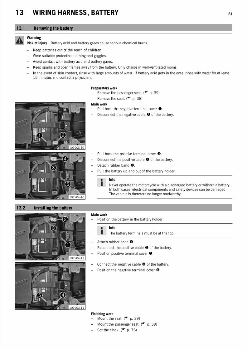
7/21/2019 Duke 390 Repair Manual (Full Version - 204pages)
http://slidepdf.com/reader/full/duke-390-repair-manual-full-version-204pages 63/204

7/21/2019 Duke 390 Repair Manual (Full Version - 204pages)
http://slidepdf.com/reader/full/duke-390-repair-manual-full-version-204pages 64/204
13 WIRING HARNESS, BATTERY 62
13.3 Disconnecting the negative cable of the battery
Preparatory work
– Remove the passenger seat. ( p. 39)
– Remove the seat. ( p. 38)
101903-10
Main work
– Pull back the negative terminal cover1.
– Disconnect the negative cable2 of the battery.
13.4 Reconnecting the negative cable of the battery
101903-10
Main work
– Connect the negative cable2 of the battery.
– Position the negative terminal cover1.
Finishing work
– Mount the seat. ( p. 39)
– Mount the passenger seat. ( p. 39)
– Set the clock. ( p. 76)
13.5 Recharging the battery
Warning
Risk of injury Battery acid and battery gases cause serious chemical burns.
– Keep batteries out of the reach of children.
– Wear suitable protective clothing and goggles.
– Avoid contact with battery acid and battery gases.
– Keep sparks and open flames away from the battery. Only charge in well-ventilated rooms.
– In the event of skin contact, rinse with large amounts of water. If battery acid gets in the eyes, rinse with water for at least15 minutes and contact a physician.
WarningEnvironmental hazard The battery contains elements that are harmful to the environment.
– Do not discard batteries with the household waste. Dispose of faulty batteries in an environmentally compatible manner.Give the battery to your authorized KTM dealer or dispose of it at a collection point for used batteries.
Info
Even when there is no load on the battery, it still loses power steadily.The charge state and the type of charge are very important for the service life of the battery.Rapid recharging with a high charging current shortens the battery's service life.If the charging current, charging voltage, and charging time are exceeded, electrolyte escapes through the safety valves. Thisreduces the battery capacity.If the battery is depleted from starting the vehicle repeatedly, the battery must be charged immediately.If the battery is left in a discharged state for an extended period, it will become over-discharged and sulfate, destroying thebattery.The battery is maintenance-free, which means that the acid level does not need to be checked.

7/21/2019 Duke 390 Repair Manual (Full Version - 204pages)
http://slidepdf.com/reader/full/duke-390-repair-manual-full-version-204pages 65/204
13 WIRING HARNESS, BATTERY 63
Preparatory work
– Switch off all power consumers and switch off the engine.
– Remove the passenger seat. ( p. 39)
– Remove the seat. ( p. 38)
– Disconnect the negative cable of the battery to avoid damage to the motorcycle'selectronics.
B01395-10
Main work
– Connect the battery charger to the battery. Switch on the battery charger.
Battery charger (58429074000)
You can also use the battery charger to test rest potential and start potential of thebattery, and to test the alternator. With this device, you cannot overcharge the bat-tery.
Info
Never remove lid 1.Charge the battery with a maximum of 10% of the capacity specified onbattery housing2.
– Switch off the charger after charging. Disconnect the battery.
GuidelineThe charge current, charge voltage and charge time must not be exceeded.
Charge the battery regularly when themotorcycle is not in use
3 months
Finishing work
– Mount the seat. ( p. 39)
– Mount the passenger seat. ( p. 39)
– Set the clock. ( p. 76)
13.6 Checking the charging voltage
Condition
The battery must be fully functional and completely charged.
Preparatory work
– Remove the passenger seat. ( p. 39)
– Remove the seat. ( p. 38)
Main work
– Start the motorcycle to make checks. ( p. 13)
304934-10
– Measure the voltage between the specified points.Measuring point Plus (+) – Measuring point Ground (−)
Charging voltage
5,000 rpm 13.5… 15.0 V
» If the displayed value is less than the specified value:
– Check the cable from the alternator to the voltage regulator.
– Check the cable from the voltage regulator to the wiring harness.
– Check the stator winding of the alternator. ( p. 156)
» If the displayed value is greater than the specified value:
– Change the voltage regulator.

7/21/2019 Duke 390 Repair Manual (Full Version - 204pages)
http://slidepdf.com/reader/full/duke-390-repair-manual-full-version-204pages 66/204

7/21/2019 Duke 390 Repair Manual (Full Version - 204pages)
http://slidepdf.com/reader/full/duke-390-repair-manual-full-version-204pages 67/204
14 BRAKE SYSTEM 65
14.1 Checking the front brake linings
Warning
Danger of accidents Reduced braking efficiency caused by worn brake linings.
– Change worn brake linings immediately.
Note
Danger of accidents Reduced braking efficiency caused by damaged brake discs.
– If the brake linings are not changed in time, the steel brake lining carriers grind on the brake disc. The braking effect is greatlyreduced and the brake discs are destroyed. Check the brake linings regularly.
B00739-10
– Check the brake linings for minimum thicknessA.
Minimum thickness A ≥ 1 mm (≥ 0.04 in)
» If the minimum thickness is less than specified:
– Change the front brake linings. ( p. 65)
– Check the brake linings for damage and cracking.
» If there is wear or tearing:
– Change the front brake linings. ( p. 65)
14.2 Changing the front brake linings
Warning
Skin irritation Brake fluid can cause skin irritation on contact.
– Avoid contact with skin and eyes, and keep out of the reach of children.
– Wear suitable protective clothing and goggles.
– If brake fluid comes into contact with the eyes, flush the eyes thoroughly with water and consult a physician immediately.
Warning
Danger of accidents Reduced braking efficiency due to old brake fluid.
– Change the brake fluid of the front and rear brake according to the service schedule.
Warning
Danger of accidents Reduced braking efficiency due to oil or grease on the brake discs.
– Always keep the brake discs free of oil and grease, and clean them with brake cleaner when necessary.
Warning
Danger of accidents Reduced braking efficiency due to use of non-approved brake linings.
– Brake linings available from accessory suppliers are often not tested and approved for use on KTM vehicles. The construc-tion and friction factor of the brake linings and therefore the brake power can differ considerably from the original KTMbrake linings. If brake linings are used that differ from the originals, there is no guarantee that they comply with the origi-
nal license. The vehicle no longer corresponds to the condition at delivery, and the warranty is no longer valid.
Warning
Environmental hazard Hazardous substances cause environmental damage.
– Oil, grease, filters, fuel, cleaners, brake fluid, etc., should be disposed of as stipulated in applicable regulations.
Info
Avoid contact between brake fluid and painted parts. Brake fluid attacks paint!Use only clean brake fluid from a sealed container.

7/21/2019 Duke 390 Repair Manual (Full Version - 204pages)
http://slidepdf.com/reader/full/duke-390-repair-manual-full-version-204pages 68/204
14 BRAKE SYSTEM 66
307304-10
– Move the brake fluid reservoir mounted on the handlebar to a horizontal position.
– Remove screws 1.
– Remove cover 2 with membrane3.
307305-10
– Remove locking clip4.
307306-10
– Remove pin5.
– Take off springs6.
307307-10
– Remove brake linings7.
– Clean the brake caliper.
307308-10
– Press the brake piston back to its basic position and make sure that no brake fluidoverflows from the brake fluid reservoir. Suction it off if necessary.
Info
Protect the components against damage.
307307-10
– Position brake linings7.
Info
Always change the brake linings in pairs.

7/21/2019 Duke 390 Repair Manual (Full Version - 204pages)
http://slidepdf.com/reader/full/duke-390-repair-manual-full-version-204pages 69/204
14 BRAKE SYSTEM 67
307306-10
– Position springs6.
The arrow on the spring points in the direction of travel.
– Mount pin5.
Info
Make sure the springs are seated correctly.
– Activate the hand brake lever until there is a firm pressure point.
307303-10
– Correct the brake fluid level to levelA.
Guideline
Level A 5 mm (0.2 in)
Brake fluid DOT 4 / DOT 5.1 ( p. 186)
– Position the cover with the membrane. Mount and tighten the screws.
Info
Clean up overflowed or spilt brake fluid immediately with water.
14.3 Checking the brake fluid level of the front brake
Warning
Danger of accidents Failure of the brake system.
– If the brake fluid level falls below the MIN mark, this indicates a leakage in the brake system or worn-out brake linings.Check the brake system and do not continue riding.
Warning
Danger of accidents Reduced braking efficiency due to old brake fluid.
– Change the brake fluid of the front and rear brake according to the service schedule.
C00200-10
– Move the brake fluid reservoir mounted on the handlebar to a horizontal position.
– Check the brake fluid level in viewer1.
» If the brake fluid is below the MIN marking:
– Add front brake fluid. ( p. 67)
14.4 Adding front brake fluid
Warning
Danger of accidents Failure of the brake system.
– If the brake fluid level falls below the MIN mark, this indicates a leakage in the brake system or worn-out brake linings.Check the brake system and do not continue riding.
Warning
Skin irritation Brake fluid can cause skin irritation on contact.
– Avoid contact with skin and eyes, and keep out of the reach of children.
– Wear suitable protective clothing and goggles.
– If brake fluid comes into contact with the eyes, flush the eyes thoroughly with water and consult a physician immediately.
WarningDanger of accidents Reduced braking efficiency due to old brake fluid.
– Change the brake fluid of the front and rear brake according to the service schedule.

7/21/2019 Duke 390 Repair Manual (Full Version - 204pages)
http://slidepdf.com/reader/full/duke-390-repair-manual-full-version-204pages 70/204
14 BRAKE SYSTEM 68
Warning
Environmental hazard Hazardous substances cause environmental damage.
– Oil, grease, filters, fuel, cleaners, brake fluid, etc., should be disposed of as stipulated in applicable regulations.
Info
Avoid contact between brake fluid and painted parts. Brake fluid attacks paint!
Use only clean brake fluid from a sealed container.
C00201-10
– Move the brake fluid reservoir mounted on the handlebar to a horizontal position.
– Remove screws 1.
– Remove cover 2 with membrane3.
– Add brake fluid to levelA.
Guideline
Level A 5 mm (0.2 in)
Brake fluid DOT 4 / DOT 5.1 ( p. 186)
– Position the cover with the membrane. Mount and tighten the screws.
Info
Clean up overflowed or spilt brake fluid immediately with water.
14.5 Changing the front brake fluid
Warning
Skin irritation Brake fluid can cause skin irritation on contact.
– Avoid contact with skin and eyes, and keep out of the reach of children.
– Wear suitable protective clothing and goggles.
– If brake fluid comes into contact with the eyes, flush the eyes thoroughly with water and consult a physician immediately.
Warning
Environmental hazard Hazardous substances cause environmental damage.
– Oil, grease, filters, fuel, cleaners, brake fluid, etc., should be disposed of as stipulated in applicable regulations.
Info
Avoid contact between brake fluid and painted parts. Brake fluid attacks paint!Use only clean brake fluid from a sealed container.
201524-10
– Move the brake fluid reservoir mounted on the handlebar to a horizontal position.
– Cover painted parts.
–
Remove screws1
. – Remove cover 2 with the membrane.
– Draw the old brake fluid out of the brake fluid reservoir using a syringe and fill withfresh brake fluid.
Bleed syringe (50329050000) ( p. 189)
Brake fluid DOT 4 / DOT 5.1 ( p. 186)
201525-10
– Mount the corresponding bleeder cover3 from the special tool set.
Bleeder cover (00029013000) ( p. 189)
– Connect the bleeding device.
Bleeding device (00029013100) ( p. 189)

7/21/2019 Duke 390 Repair Manual (Full Version - 204pages)
http://slidepdf.com/reader/full/duke-390-repair-manual-full-version-204pages 71/204
14 BRAKE SYSTEM 69
201494-10
– Open shut-off valve4.
Info
Follow the operating instructions of the bleeding device.
– Ensure that the filling pressure is set on pressure gaugeA. Correct the filling pres-sure on pressure regulator B if necessary.
Guideline
Filling pressure 2… 2.5 bar (29… 36 psi)
307302-10
– Pull off dust cap5 of the bleeder screw of the brake caliper. Connect the bleederbottle hose.
Bleeding device (00029013100) ( p. 189)
– Open bleeder screw6 by approximately one half turn.
Info
Drain until fresh brake fluid emerges in the bleeder bottle hose without bub-bles.
–
Tighten the bleeder screw. – Close shut-off valve4.
– Open the bleeder screw again until no more brake fluid emerges.
Info
Overfilling of the brake fluid reservoir is prevented.
– Tighten the bleeder screw. Remove the bleeder bottle hose. Attach the dust cap.
– Disconnect the bleeding device. Remove the bleeder cover.
307303-10
– Correct the brake fluid level to levelA.
Guideline
Level A 5 mm (0.2 in)
Brake fluid DOT 4 / DOT 5.1 ( p. 186)
– Position the cover with the membrane. Mount and tighten the screws.
Info
Clean up overflowed or spilt brake fluid immediately with water.
– Check the hand brake lever for a firm pressure point.
14.6 Checking the rear brake linings
Warning
Danger of accidents Reduced braking efficiency caused by worn brake linings.
– Change worn brake linings immediately.
Note
Danger of accidents Reduced braking efficiency caused by damaged brake discs.
– If the brake linings are not changed in time, the steel brake lining carriers grind on the brake disc. The braking effect is greatlyreduced and the brake discs are destroyed. Check the brake linings regularly.
B01390-10
– Check the brake linings for minimum thicknessA.
Minimum thickness A ≥ 1 mm (≥ 0.04 in)
» If the minimum thickness is less than specified:
– Change the rear brake linings. ( p. 70)
– Check the brake linings for damage and cracking.
» If there is wear or tearing:
– Change the rear brake linings. ( p. 70)

7/21/2019 Duke 390 Repair Manual (Full Version - 204pages)
http://slidepdf.com/reader/full/duke-390-repair-manual-full-version-204pages 72/204
14 BRAKE SYSTEM 70
14.7 Changing the rear brake linings
Warning
Skin irritation Brake fluid can cause skin irritation on contact.
– Avoid contact with skin and eyes, and keep out of the reach of children.
– Wear suitable protective clothing and goggles.
– If brake fluid comes into contact with the eyes, flush the eyes thoroughly with water and consult a physician immediately.
Warning
Danger of accidents Reduced braking efficiency due to old brake fluid.
– Change the brake fluid of the front and rear brake according to the service schedule.
Warning
Danger of accidents Reduced braking efficiency due to oil or grease on the brake discs.
– Always keep the brake discs free of oil and grease, and clean them with brake cleaner when necessary.
Warning
Danger of accidents Reduced braking efficiency due to use of non-approved brake linings.
– Brake linings available from accessory suppliers are often not tested and approved for use on KTM vehicles. The construc-tion and friction factor of the brake linings and therefore the brake power can differ considerably from the original KTMbrake linings. If brake linings are used that differ from the originals, there is no guarantee that they comply with the origi-nal license. The vehicle no longer corresponds to the condition at delivery, and the warranty is no longer valid.
Warning
Environmental hazard Hazardous substances cause environmental damage.
– Oil, grease, filters, fuel, cleaners, brake fluid, etc., should be disposed of as stipulated in applicable regulations.
Info
Avoid contact between brake fluid and painted parts. Brake fluid attacks paint!Use only clean brake fluid from a sealed container.
308262-10
– Stand the vehicle upright.
– Remove screw cap1 and membrane 2.
– Push the brake caliper toward the brake disc with your hand to push back the brakepiston; ensure that brake fluid does not runs out of the brake fluid reservoir, remov-ing it if it does.
308263-10
– Remove locking clips3.
– Remove pin4.
308264-10
– Remove brake linings5.
– Clean the brake caliper.

7/21/2019 Duke 390 Repair Manual (Full Version - 204pages)
http://slidepdf.com/reader/full/duke-390-repair-manual-full-version-204pages 73/204
14 BRAKE SYSTEM 71
308265-10
– Position brake linings5.
– Mount pin4.
308263-11
– Mount locking clips3.
308262-11
– Operate the foot brake lever repeatedly until the brake linings are in contact withthe brake disc and there is a pressure point.
– Add brake fluid to the MAX marking.
Brake fluid DOT 4 / DOT 5.1 ( p. 186)
– Mount the screw cap with the washer and membrane.
Info
Clean up overflowed or spilt brake fluid immediately with water.
14.8 Checking the free travel of foot brake lever
Warning
Danger of accidents Brake system failure.
– If there is no free travel on the foot brake lever, pressure builds up on the rear brake circuit. The rear brake can fail due tooverheating. Adjust the free travel on foot brake lever according to specifications.
101897-10
– Disconnect spring1.
– Move the foot brake lever back and forth between the end stop and the contact tothe foot brake cylinder piston and check free travel A.
Guideline
Free travel at foot brake lever 3… 5 mm (0.12… 0.2 in)
» If the free travel does not meet specifications: – Adjust the free travel of the foot brake lever. ( p. 72)
– Reconnect spring1.

7/21/2019 Duke 390 Repair Manual (Full Version - 204pages)
http://slidepdf.com/reader/full/duke-390-repair-manual-full-version-204pages 74/204
14 BRAKE SYSTEM 72
14.9 Adjusting the free travel of the foot brake lever
Warning
Danger of accidents Brake system failure.
– If there is no free travel on the foot brake lever, pressure builds up on the rear brake circuit. The rear brake can fail due tooverheating. Adjust the free travel on foot brake lever according to specifications.
101897-11
– Disconnect spring1.
– Release nut 2 and use screw 3 to adjust the specified free travel A.
Guideline
Free travel at foot brake lever 3… 5 mm (0.12… 0.2 in)
Info
The range of adjustment is limited.
– Hold screw3 and tighten nut 2.
– Attach spring1.
14.10 Checking the rear brake fluid level
Warning
Danger of accidents Failure of the brake system.
– If the brake fluid level falls below the MIN mark, this indicates a leakage in the brake system or worn-out brake linings.Check the brake system and do not continue riding.
Warning
Danger of accidents Reduced braking efficiency due to old brake fluid.
– Change the brake fluid of the front and rear brake according to the service schedule.
101898-10
– Stand the vehicle upright.
– Check the brake fluid level in the brake fluid reservoir.
» If the fluid level reaches the MIN marking 1:
– Add rear brake fluid. ( p. 73)

7/21/2019 Duke 390 Repair Manual (Full Version - 204pages)
http://slidepdf.com/reader/full/duke-390-repair-manual-full-version-204pages 75/204
14 BRAKE SYSTEM 73
14.11 Adding rear brake fluid
Warning
Danger of accidents Failure of the brake system.
– If the brake fluid level falls below the MIN mark, this indicates a leakage in the brake system or worn-out brake linings.Check the brake system and do not continue riding.
WarningSkin irritation Brake fluid can cause skin irritation on contact.
– Avoid contact with skin and eyes, and keep out of the reach of children.
– Wear suitable protective clothing and goggles.
– If brake fluid comes into contact with the eyes, flush the eyes thoroughly with water and consult a physician immediately.
Warning
Danger of accidents Reduced braking efficiency due to old brake fluid.
– Change the brake fluid of the front and rear brake according to the service schedule.
Warning
Environmental hazard Hazardous substances cause environmental damage.
– Oil, grease, filters, fuel, cleaners, brake fluid, etc., should be disposed of as stipulated in applicable regulations.
Info
Avoid contact between brake fluid and painted parts. Brake fluid attacks paint!Use only clean brake fluid from a sealed container.
101899-10
– Stand the vehicle upright.
– Remove screw cap1 with membrane2.
– Add brake fluid to levelA.
Brake fluid DOT 4 / DOT 5.1 ( p. 186)
– Refit screw cap with membrane.
Info
Clean up overflowed or spilt brake fluid immediately with water.
14.12 Changing the rear brake fluid
Warning
Skin irritation Brake fluid can cause skin irritation on contact.
– Avoid contact with skin and eyes, and keep out of the reach of children.
– Wear suitable protective clothing and goggles.
– If brake fluid comes into contact with the eyes, flush the eyes thoroughly with water and consult a physician immediately.
Warning
Environmental hazard Hazardous substances cause environmental damage.
– Oil, grease, filters, fuel, cleaners, brake fluid, etc., should be disposed of as stipulated in applicable regulations.
Info
Avoid contact between brake fluid and painted parts. Brake fluid attacks paint!Use only clean brake fluid from a sealed container.

7/21/2019 Duke 390 Repair Manual (Full Version - 204pages)
http://slidepdf.com/reader/full/duke-390-repair-manual-full-version-204pages 76/204
14 BRAKE SYSTEM 74
308266-10
– Cover painted parts.
– Remove screw cap1 with membrane.
– Draw the old brake fluid out of the brake fluid reservoir using a syringe and fill withfresh brake fluid.
Bleed syringe (50329050000) ( p. 189)
Brake fluid DOT 4 / DOT 5.1 ( p. 186)
308267-10
– Mount the corresponding bleeder cover2 from the special tool set.
Bleeder cover (00029013000) ( p. 189)
– Connect the bleeding device.
Bleeding device (00029013100) ( p. 189)
201494-11
– Open shut-off valve3.
Info
Follow the operating instructions of the bleeding device.
– Ensure that the filling pressure is set on pressure gaugeA. Correct the filling pres-sure on pressure regulator B if necessary.
Guideline
Filling pressure 2… 2.5 bar (29… 36 psi)
308268-10
– Pull off dust cap4 of the bleeder screw. Connect the bleeder bottle hose.
Bleeding device (00029013100) ( p. 189)
– Open bleeder screw5 by approximately one half turn.
Info
Drain until fresh brake fluid emerges in the bleeder bottle hose without bub-bles.
– Tighten the bleeder screw.
– Close shut-off valve3.
– Open the bleeder screw again until no more brake fluid emerges.
Info
Overfilling of the brake fluid reservoir is prevented.
– Tighten the bleeder screw. Remove the bleeder bottle hose. Attach the dust cap.
– Disconnect the bleeding device. Remove the bleeder cover.
308269-10
– Stand the vehicle upright.
– Correct the brake fluid to levelA.
Brake fluid DOT 4 / DOT 5.1 ( p. 186)
– Refit screw cap with membrane.
Info
Clean up overflowed or spilt brake fluid immediately with water.
– Check the foot brake lever for a firm pressure point.

7/21/2019 Duke 390 Repair Manual (Full Version - 204pages)
http://slidepdf.com/reader/full/duke-390-repair-manual-full-version-204pages 77/204
15 LIGHTING SYSTEM, INSTRUMENTS 75
15.1 Setting kilometers or miles
Info
Make the country-specific setting.
Condition
The ignition is on.The motorcycle is stationary.
401303-01
– Press the MODE button briefly and repeatedly until ODO appears on the display.
– Press the MODE button for 5 - 10 seconds.
The display changes from km/h to mph or from mph to km/h.
15.2 Adjusting the shift speed RPM 1Condition
The ignition is on.The motorcycle is stationary.
401307-01
– Press the MODE button briefly and repeatedly until TRIP 2 appears on the display.
– Press the MODE button for 5 - 10 seconds.
The display RPM 1 appears.
Info
The engine speed can be set at intervals of 50.RPM 1 is the engine speed above which the shift warning light starts toflash.
– Set the speed with the MODE and SET buttons.
Info
The MODE button increases the value.The SET button decreases the value.
– Do not activate the two buttons for approx. 15 seconds.
The display RPM 1 goes out and the set speed is stored.
15.3 Adjusting the shift speed RPM 2
Condition
The ignition is on.
The motorcycle is stationary.
401308-01
– Press the MODE button briefly and repeatedly until TRIP 2 appears on the display.
– Press the SET button for 5 - 10 seconds.
The display RPM 2 appears.
Info
The engine speed can be set at intervals of 50.RPM 2 is the engine speed above which the shift warning light lights up con-stantly.The speed RPM 2 must always be higher than the speed RPM 1.
– Set the speed with the MODE and SET buttons.
Info
The MODE button increases the value.The SET button decreases the value.

7/21/2019 Duke 390 Repair Manual (Full Version - 204pages)
http://slidepdf.com/reader/full/duke-390-repair-manual-full-version-204pages 78/204
15 LIGHTING SYSTEM, INSTRUMENTS 76
– Do not activate the two buttons for approx. 15 seconds.
The display RPM 2 goes out and the set speed is stored.
15.4 Setting the time
Condition
The ignition is on.The motorcycle is stationary.
401303-01
– Press the MODE button briefly and repeatedly until ODO appears on the display.
– Press the MODE and SET buttons for 5 - 10 seconds.
The time display begins to flash.
– Set the hours display using the MODE button.
– Set the minutes display using the SET button.
– Press the MODE and SET buttons for 5 - 10 seconds.
The time is set.
15.5 Resetting the service interval display
Condition
The ignition is on.The engine is switched off.The motorcycle is stationary.
401358-01
– Press the SET button for more than 10 seconds.
Info
The service interval display can only be reset. It is not possible to individu-ally adjust the distance or time to the next required service.
15.6 Checking the headlight setting
0AA
0BB
400726-10
– Position the vehicle upright on a horizontal surface in front of a light wall and makea mark at the height of the center of the low beam headlight.
– Make another mark at a distanceB under the first mark.
Guideline
Distance B 5 cm (2 in)
– Position the vehicle vertically at a distance A in front of the wall and switch on thelow beam.
GuidelineDistance A 5 m (16 ft)
– The rider, with luggage and passenger if applicable, now mounts the motorcycle.
– Check the headlight setting.
The light-dark boundary must lie exactly on the lower mark when the motorcycleis ready to operate with the rider mounted along with any luggage and a passen-ger if applicable.
» If the boundary between light and dark does not meet specifications:
– Adjust the headlight range. ( p. 77)

7/21/2019 Duke 390 Repair Manual (Full Version - 204pages)
http://slidepdf.com/reader/full/duke-390-repair-manual-full-version-204pages 79/204
15 LIGHTING SYSTEM, INSTRUMENTS 77
15.7 Adjusting the headlight range
101907-10
Main work
– Remove expanding rivets1.
101908-10
– Remove screws 2.
– Lift the headlight mask slightly and swing forward.
B00764-10
– Adjust the beam distance of the headlight by turning screw3.
Guideline
For a motorcycle with rider, and with luggage and a passenger if applicable, thelight/dark boundary must be exactly on the lower mark (applied in: Checkingheadlight adjustment).
Info
Turn clockwise to increase the headlight range; turn counterclockwise toreduce the headlight range.
101908-10
– Fold the headlight mask up. – Mount and tighten screws2.
Guideline
Screw, headlight mask M6 11 Nm (8.1 lbf ft)
101907-10
– Mount expanding rivets1 on both sides.
Finishing work
– Check the headlight setting. ( p. 76)

7/21/2019 Duke 390 Repair Manual (Full Version - 204pages)
http://slidepdf.com/reader/full/duke-390-repair-manual-full-version-204pages 80/204
15 LIGHTING SYSTEM, INSTRUMENTS 78
15.8 Changing the parking light bulb
Note
Damage to reflector Reduced brightness.
– Grease on the lamp will evaporate due to the heat and be deposited on the reflector. Clean the lamp and keep it free of greasebefore mounting.
Preparatory work
– Switch off all power consumers and switch off the engine.
101907-10
Main work
– Remove expanding rivets1.
308243-10
– Remove screws 2.
– Lift the headlight mask slightly and swing forward.
B00762-10
– Remove screws 3.
– Take off cover4.
B00763-10
– Pull the socket with bulb5 out of the housing.
– Remove the bulb.
– Position a new light bulb in the socket.
Parking light (W5W/socket W2.1x9.5d) ( p. 160)
– Position the socket with bulb5 in the housing.

7/21/2019 Duke 390 Repair Manual (Full Version - 204pages)
http://slidepdf.com/reader/full/duke-390-repair-manual-full-version-204pages 81/204
15 LIGHTING SYSTEM, INSTRUMENTS 79
B00762-10
– Position cover4.
– Mount and tighten screws3.
308243-10
– Fold the headlight mask up.
– Mount and tighten screws2.
Guideline
Screw, headlight mask M6 11 Nm (8.1 lbf ft)
101907-10
– Mount expanding rivets1 on both sides.
– Check that the lighting is functioning properly.
15.9 Changing the headlight bulb
Note
Damage to reflector Reduced brightness.
– Grease on the lamp will evaporate due to the heat and be deposited on the reflector. Clean the lamp and keep it free of greasebefore mounting.
Preparatory work
– Switch off all power consumers and switch off the engine.
101907-10
Main work
– Remove expanding rivets1.
101908-10
– Remove screws 2.
– Lift the headlight mask slightly and swing forward.

7/21/2019 Duke 390 Repair Manual (Full Version - 204pages)
http://slidepdf.com/reader/full/duke-390-repair-manual-full-version-204pages 82/204
15 LIGHTING SYSTEM, INSTRUMENTS 80
B00760-10
– Take off protection cap3.
– Disconnect plug-in connector4.
B00761-10
– Detach retaining clamp5.
– Remove headlight bulb6.
– Position the new headlight bulb in the headlight housing.
Headlight (H4/socket P43t) ( p. 160)
Info
Insert the headlight bulb so that the catches latch into the recesses.
– Attach retaining clamp5.
B00760-10
– Connect plug-in connection4.
– Mount protection cap3.
101908-10
– Fold the headlight mask up.
– Mount and tighten screws2.
Guideline
Screw, headlight mask M6 11 Nm (8.1 lbf ft)
101907-10
– Mount expanding rivets1 on both sides.
– Check that the lighting is functioning properly.

7/21/2019 Duke 390 Repair Manual (Full Version - 204pages)
http://slidepdf.com/reader/full/duke-390-repair-manual-full-version-204pages 83/204

7/21/2019 Duke 390 Repair Manual (Full Version - 204pages)
http://slidepdf.com/reader/full/duke-390-repair-manual-full-version-204pages 84/204
16 ENGINE 82
308309-10
– Detach spark plug connector6.
308310-10
– Remove screws 7.
– Remove screw8.
– Take off the engine sprocket cover.
308311-10
– Remove screws 9 and take off the lock washer.
308312-10
– Remove nut bk with washer.
– Take off chain adjuster bl.
– Push the rear wheel into the foremost position.
308313-10
– Pull the engine sprocket off of the countershaft and remove it.
308314-10
– Remove screw bm.
– Pull off the shift linkage and hang it to one side.

7/21/2019 Duke 390 Repair Manual (Full Version - 204pages)
http://slidepdf.com/reader/full/duke-390-repair-manual-full-version-204pages 85/204
16 ENGINE 83
308315-10
– Push back the rubber cap.
– Remove nut bn with washer.
308316-10
– Expose the cable and unplug connectors bo and bp.
308317-10
– Expose the cable and unplug connector bq.
308318-10
– Release hose clip br.
– Push the throttle valve body upward out of the intake flange.
308319-10
– Remove screws bs.
– Remove fitting bt.
– Remove both engine fixing arms.
308320-10
– Push back hose clamps ck and cl.
– Pull off the radiator hoses.

7/21/2019 Duke 390 Repair Manual (Full Version - 204pages)
http://slidepdf.com/reader/full/duke-390-repair-manual-full-version-204pages 86/204
16 ENGINE 84
308321-10
– Push back hose clamp cm.
– Pull off the radiator hose.
308322-10
– Remove screws cn.
– Pull off the radiator pipe and hang it to one side.
308323-10
– Remove screws co.
– Take off the retaining bracket.
308324-10
– Position the floor jack under the engine and fix it using the special tool.
Floor jack attachment (75029055000) ( p. 192)
308325-10
– Remove fitting cp.
– Remove fitting cq.
– Remove the cable binder.
– Hang ground wire cr to the side.

7/21/2019 Duke 390 Repair Manual (Full Version - 204pages)
http://slidepdf.com/reader/full/duke-390-repair-manual-full-version-204pages 87/204
16 ENGINE 85
308326-10
– Lower the engine.
Info
You should have an assistant for this step.Make sure that the engine is sufficiently secured against falling over.Protect the frame and attachments from damage.
16.2 Installing the engine
Preparatory work
– Lift the motor onto the special tool and secure it.
Floor jack attachment (75029055000) ( p. 192)
308326-10
Main work
– Position the engine in the frame.
Info
It is useful to draw on the help of an assistant.Protect the frame and attachments against damage.
308325-11
– Position ground wire1 and secure it with a cable binder.
– Mount fitting2 but do not tighten yet.
Guideline
Fitting, engine mounting bracket M10 55 Nm(40.6 lbf ft)
– Mount fitting3 but do not tighten yet.Guideline
Fitting, engine mounting bracket M10 55 Nm(40.6 lbf ft)
308324-10
– Remove the floor jack with the special tool.
Floor jack attachment (75029055000) ( p. 192)

7/21/2019 Duke 390 Repair Manual (Full Version - 204pages)
http://slidepdf.com/reader/full/duke-390-repair-manual-full-version-204pages 88/204
16 ENGINE 86
308323-11
– Position the retaining bracket.
– Mount and tighten screws4.
Guideline
Remaining screws, chassis M6 10 Nm (7.4 lbf ft)
308322-11
– Mount the radiator pipe with the O-ring.
– Mount and tighten screws5.
Guideline
Remaining screws, chassis M6 10 Nm (7.4 lbf ft)
308321-11
– Mount the radiator hose.
– Position hose clamp6.
308320-11
– Mount the radiator hoses.
– Position hose clamps7 and8.
308327-10
– Tighten fittings2 and3.
Guideline
Fitting, engine mounting bracket M10 55 Nm(40.6 lbf ft)
308319-11
– Position both engine fixing arms.
– Mount and tighten screws9.
Guideline
Screw, engine bearer on frame M8 30 Nm(22.1 lbf ft)
– Mount and tighten fitting bk.
Guideline
Fitting, engine mounting bracket M10 55 Nm(40.6 lbf ft)

7/21/2019 Duke 390 Repair Manual (Full Version - 204pages)
http://slidepdf.com/reader/full/duke-390-repair-manual-full-version-204pages 89/204
16 ENGINE 87
308318-11
– Position the throttle valve body in the intake flange.
– Tighten hose clip bl.
308317-11
– Plug in connector bm.
– Position the cable and secure with cable binders.
308316-11
– Plug in connectors bn and bo.
– Position the cable and secure with cable binders.
308315-11
– Mount and tighten nut bp with the washer.
Guideline
Remaining nuts, chassis M5 3 Nm (2.2 lbf ft)
– Position the rubber cap.
308314-11
– Position the shift linkage.
– Mount and tighten screw bq.
Guideline
Screw, shift activation M6 11 Nm
(8.1 lbf ft)
Loctite® 243™
308313-10
– Position the engine sprocket in the chain and slide onto the countershaft.

7/21/2019 Duke 390 Repair Manual (Full Version - 204pages)
http://slidepdf.com/reader/full/duke-390-repair-manual-full-version-204pages 90/204
16 ENGINE 88
308312-11
– Pull the rear wheel toward the rear.
– Mount chain adjuster br.
– Mount and tighten nut bs with the washer.
Guideline
For the rear wheel to be aligned correctly, the markings on the left and right ofthe chain adjuster must be in the same position as the reference marks.
Nut, rear wheel spindle M14x1.5 90 Nm(66.4 lbf ft)
308311-11
– Mount the lock washer and turn it slightly.
The lock washer engages in the gear teeth of the countershaft.
– Mount and tighten screws bt.
Guideline
Remaining nuts, chassis M6 15 Nm(11.1 lbf ft)
308310-11
– Position the engine sprocket cover.
– Mount and tighten screws ck.
Guideline
Remaining nuts, chassis M6 15 Nm(11.1 lbf ft)
– Mount and tighten screw cl.
Guideline
Remaining nuts, chassis M6 15 Nm(11.1 lbf ft)
308309-11
– Mount the spark plug connector cm.
308308-11
– Mount the vent hose.
– Position hose clamp cn.
308307-11
– Plug in connector co.

7/21/2019 Duke 390 Repair Manual (Full Version - 204pages)
http://slidepdf.com/reader/full/duke-390-repair-manual-full-version-204pages 91/204

7/21/2019 Duke 390 Repair Manual (Full Version - 204pages)
http://slidepdf.com/reader/full/duke-390-repair-manual-full-version-204pages 92/204
16 ENGINE 90
16.3 Disassembling the engine
16.3.1 Preparations
307956-10
– Mount special tools1 and2 on the engine assembly stand.
Engine fixing arm (90129002060) ( p. 194)
Engine fixing arm (90129002050) ( p. 193)
Engine assembly stand (61229001000) ( p. 192)
– Mount the engine on special tool.
Info
Have an assistant help you or use a crane.
16.3.2 Draining the engine oil
307957-10
– Remove oil drain plug1 with the O-ring.
307958-10
– Remove oil screen2 with the O-ring.
– Completely drain the engine oil.
307959-10
– Remove screw plug 3 with the O-ring and oil screen.
16.3.3 Removing the chain securing guide
307960-10
– Remove screws 1.
– Take off the chain securing guide.

7/21/2019 Duke 390 Repair Manual (Full Version - 204pages)
http://slidepdf.com/reader/full/duke-390-repair-manual-full-version-204pages 93/204
16 ENGINE 91
16.3.4 Removing the valve cover
307961-10
– Remove screws 1 with the gasket.
– Take off the valve cover with the valve cover seal.
307962-10
– Take off gasket2.
307963-10
– Remove the spark plug shaft insert3.
16.3.5 Removing the spark plug
307966-10
– Remove the spark plug using special tool 1.
Spark plug wrench (77229172000) ( p. 193)
16.3.6 Removing the clutch cover
307972-10
– Remove screws 1.

7/21/2019 Duke 390 Repair Manual (Full Version - 204pages)
http://slidepdf.com/reader/full/duke-390-repair-manual-full-version-204pages 94/204

7/21/2019 Duke 390 Repair Manual (Full Version - 204pages)
http://slidepdf.com/reader/full/duke-390-repair-manual-full-version-204pages 95/204

7/21/2019 Duke 390 Repair Manual (Full Version - 204pages)
http://slidepdf.com/reader/full/duke-390-repair-manual-full-version-204pages 96/204
16 ENGINE 94
307982-10
– Remove intake camshaft 2.
307983-10
– Remove exhaust camshaft 3.
16.3.10 Removing the cylinder head
307985-10
– Remove screws 1.
307986-10
– Release screws 2 in a crisscross pattern and remove them with the washers.
– Take off the cylinder head.
307987-10
– Take off the cylinder head gasket 3.
– Remove dowels 4.
307988-10
– Remove timing chain guide rail5.

7/21/2019 Duke 390 Repair Manual (Full Version - 204pages)
http://slidepdf.com/reader/full/duke-390-repair-manual-full-version-204pages 97/204
16 ENGINE 95
16.3.11 Removing the piston
307990-10
– Push the cylinder upward.
Info
Push the cylinder upward only far enough to allow removal of the piston pin.
– Remove piston pin retainer1.
– Remove the piston pin.
– Take off the cylinder with the piston.
– Push the piston upward out of the cylinder.
Info
If no other work is required on the cylinder and the piston, you can leave thepiston in the cylinder.
307991-10
– Take off cylinder base gasket2.
– Remove dowels 3.
16.3.12 Removing the starter motor
307997-10
– Remove screws 1.
– Take off the starter motor.
16.3.13 Removing the timing chain
307998-10
– Feed out timing chain1.
Info
If the timing chain is to be reused, mark the direction of travel.
307999-10
– Remove screw2.
– Take off the timing chain tensioning rail toward the top.

7/21/2019 Duke 390 Repair Manual (Full Version - 204pages)
http://slidepdf.com/reader/full/duke-390-repair-manual-full-version-204pages 98/204
16 ENGINE 96
16.3.14 Removing the water pump wheel
308000-10
– Remove screws 1.
– Remove the water pump cover with the gasket.
308001-10
– Remove locating pins 2.
308002-10
– Remove nut3 with washer.
– Take off the water pump impeller4.
16.3.15 Removing the alternator cover
308003-10
– Remove screws 1.
– Take off the alternator cover.
308004-10
–
Remove dowels2
. – Take off alternator cover gasket3.

7/21/2019 Duke 390 Repair Manual (Full Version - 204pages)
http://slidepdf.com/reader/full/duke-390-repair-manual-full-version-204pages 99/204
16 ENGINE 97
16.3.16 Removing the rotor
308005-10
– Remove screw1 with the washer.
308066-10
– Mount special tool2 in the crankshaft.
Pressure screw for crankshaft (90129020000) ( p. 194)
– Mount special tool3 on the rotor.
Info
Left-handed thread!
–
Hold it tight using the special tool and pull off the rotor by turning the screw in.Puller for rotor (90229009000) ( p. 196)
– Remove the spring washer.
16.3.17 Removing the starter drive
308007-10
– Take off torque limiter1.
– Remove starter idler gear2.
308008-10
– Remove screw3.
– Remove the retaining bracket.
308009-10
– Remove freewheel gear 4.

7/21/2019 Duke 390 Repair Manual (Full Version - 204pages)
http://slidepdf.com/reader/full/duke-390-repair-manual-full-version-204pages 100/204
16 ENGINE 98
16.3.18 Removing the balancer shaft drive wheel
308010-10
– Remove screw1 with the washer.
308011-10
– Remove balancer shaft gear2 with a wedge.
308012-10
– Remove nut3 with washers.
Castle nut wrench; ½" drive (90129022000) ( p. 194)
– Take off drive wheel of the balancer shaft.
– Remove the spring washer.
16.3.19 Removing the gear position sensor
308014-10
– Remove screws 1.
– Take off the retaining bracket.
– Remove screws 2.
– Pull off the ignition pulse generator.
308015-10
–
Remove screws3
. – Take off the gear position sensor and ignition pulse generator with the cable.

7/21/2019 Duke 390 Repair Manual (Full Version - 204pages)
http://slidepdf.com/reader/full/duke-390-repair-manual-full-version-204pages 101/204
16 ENGINE 99
308016-10
– Remove contact pin3 and the contact spring.
16.3.20 Removing the suction pump
308017-10
– Remove screws 1.
– Take off the oil pump housing of the suction pump.
308018-10
– Remove dowels 2.
308019-10
– Remove external rotor3 and internal rotor 4.
308020-10
– Take off pin5.

7/21/2019 Duke 390 Repair Manual (Full Version - 204pages)
http://slidepdf.com/reader/full/duke-390-repair-manual-full-version-204pages 102/204
16 ENGINE 100
16.3.21 Removing the spacer
308022-10
– Remove the spacer1 of the countershaft.
16.3.22 Removing the clutch cage
308023-10
– Loosen screws1 in a crisscross pattern and remove together with the washers andthe clutch springs.
– Take off pressure cap2.
308024-10
– Remove pull rod3.
– Remove clutch discs4.
308025-10
– Take off support ring and pretension ring5.
308026-10
–
Hold the clutch basket using the special tool.Clutch holder (51129003000) ( p. 189)
– Remove nut6 with washer.
Info
Left-handed thread!

7/21/2019 Duke 390 Repair Manual (Full Version - 204pages)
http://slidepdf.com/reader/full/duke-390-repair-manual-full-version-204pages 103/204
16 ENGINE 101
308027-10
– Take off inner clutch hub 7 and washer 8.
Info
The washer usually sticks to the inner clutch hub.
– Take off clutch basket9.
308028-10
– Remove collar sleeve bk.
16.3.23 Removing the primary gear
308030-10
– Remove nut1 with washer.
308031-10
– Remove washer 2.
308032-10
– Remove the timing chain sprocket3.
308033-10
– Remove primary gear4.
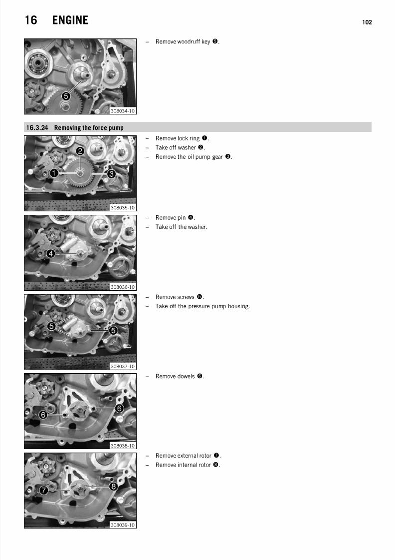
7/21/2019 Duke 390 Repair Manual (Full Version - 204pages)
http://slidepdf.com/reader/full/duke-390-repair-manual-full-version-204pages 104/204
16 ENGINE 102
308034-10
– Remove woodruff key5.
16.3.24 Removing the force pump
308035-10
– Remove lock ring1.
– Take off washer2.
– Remove the oil pump gear3.
308036-10
– Remove pin4.
– Take off the washer.
308037-10
– Remove screws 5.
– Take off the pressure pump housing.
308038-10
– Remove dowels 6.
308039-10
– Remove external rotor7.
– Remove internal rotor8.

7/21/2019 Duke 390 Repair Manual (Full Version - 204pages)
http://slidepdf.com/reader/full/duke-390-repair-manual-full-version-204pages 105/204
16 ENGINE 103
308040-10
– Remove pin9.
– Remove the oil pump shaft bk.
16.3.25 Removing the shift shaft
308044-10
– Push sliding plate1 away from the shift drum locating 2. Remove shift shaft 3with the washer.
16.3.26 Removing the shift drum locating
308045-10
– Remove screw1.
– Press locking lever2 away from shift drum locating 3 and take off the shift drumlocating.
– Release the locking lever.
16.3.27 Removing the locking lever
308046-10
– Remove screw1.
– Take off locking lever2 together with the washers and spring.
16.3.28 Removing the oil filter
308047-10
– Remove screws 1.
– Remove the oil filter cover2 with the O-ring.

7/21/2019 Duke 390 Repair Manual (Full Version - 204pages)
http://slidepdf.com/reader/full/duke-390-repair-manual-full-version-204pages 106/204
16 ENGINE 104
308048-10
– Pull oil filter3 out of the oil filter housing.
Circlip pliers reverse (51012011000) ( p. 189)
16.3.29 Removing the left engine case
308055-10
– Remove special tool1.
Engine blocking screw (61229015000) ( p. 192)
308056-10
– Remove screw2.
308057-10
– Remove screws 3.
– Swing the left section of the engine case up and remove the fitting of the engine fixing arm.

7/21/2019 Duke 390 Repair Manual (Full Version - 204pages)
http://slidepdf.com/reader/full/duke-390-repair-manual-full-version-204pages 107/204
16 ENGINE 105
308067-10
– Mount special tool4.
Pressure screw for crankshaft (90129020000) ( p. 194)
308068-10
– Mount special tool5 with suitable screws.
Case separating tool (90129048100) ( p. 195)
Info
Use the drill hole marked with 902.
– Pull off the section of the engine case by screwing in the screw.
Info
Do not wedge the engine case section.The washer of the main shaft usually sticks to the bearing.
– Take off the left section of the engine case.
– Remove the special tool.
309196-10
– Remove dowels 6.
16.3.30 Removing the shift rails
308059-10
– Remove shift rail1 together with upper spring and the lower spring.
– Remove shift rail2.
16.3.31 Removing the shift drum
308060-10
– Swing shift forks1 to one side.
– Remove shift drum2.

7/21/2019 Duke 390 Repair Manual (Full Version - 204pages)
http://slidepdf.com/reader/full/duke-390-repair-manual-full-version-204pages 108/204
16 ENGINE 106
16.3.32 Removing the shift forks
308061-10
– Remove shift forks1.
16.3.33 Removing the transmission shafts
308063-10
– Pull both transmission shafts1 out of the bearing seats together.
16.3.34 Removing the balancer shaft
308064-10
– Remove screw1.
– Take off the lock washer.
– Remove balancer shaft2.
16.3.35 Removing the crankshaft
308065-10
– Remove crankshaft 1.

7/21/2019 Duke 390 Repair Manual (Full Version - 204pages)
http://slidepdf.com/reader/full/duke-390-repair-manual-full-version-204pages 109/204
16 ENGINE 107
16.4 Work on individual parts
16.4.1 Work on the left section of the engine case
309198-10
– Remove all dowels.
– Remove lock ring1.
– Remove shaft seal ring2 of the shift shaft and 3 of the countershaft.
– Remove oil nozzle4. – Remove any sealing mass remnants and clean the engine case section thoroughly.
– Warm the engine case section in an oven.
Guideline
150 °C (302 °F)
– Knock the engine case section against a level wooden plate. This will cause thebearings to drop out of the bearing seats.
Info
Any bearings that remain in the engine case section must be removed usinga suitable tool.
– Insert the new cold bearings into the bearing seats of the hot engine case sectionand, if necessary, use a suitable press drift to push the bearing all the way to thestop or so that it is flush.
Info
When pressing the bearing in, ensure that the engine case section is level toprevent damage.Only press the bearings in via the outer ring; otherwise, the bearings will bedamaged when they are pressed in.
– After the engine case section has cooled, check that the bearings are firmly seated.
Info
If the bearings are not firmly seated after cooling, it is likely that they will
rotate in the engine case when warm. In this case, the engine case must berenewed.
– Mount the dowels.
– Press in shaft seal ring 2 of the shift shaft with the open side facing inward so thatit is flush.
– Press in shaft seal ring 3 of the countershaft with the open side facing inward sothat it is flush.
– Mount lock ring1.
– Mount and tighten oil nozzle4.
Guideline
Oil nozzle M5 6 Nm
(4.4 lbf ft)
Loctite® 243™
– Blow out the oil channel with compressed air and check that it is clear.

7/21/2019 Duke 390 Repair Manual (Full Version - 204pages)
http://slidepdf.com/reader/full/duke-390-repair-manual-full-version-204pages 110/204
16 ENGINE 108
16.4.2 Work on the right section of the engine case
308074-10
– Remove all dowels.
– Remove screws 1. Remove the bearing retainers.
– Remove oil nozzle2.
– Remove nozzle 3.
– Remove any sealing mass remnants and clean the engine case section thoroughly.
– Warm the engine case section in an oven.
Guideline
150 °C (302 °F)
– Knock the engine case section against a level wooden plate. This will cause thebearings to drop out of the bearing seats.
Info
Any bearings that remain in the engine case section must be removed usinga suitable tool.
– Insert the new cold bearings into the bearing seats of the hot engine case sectionand, if necessary, use a suitable press drift to push the bearing all the way to the
stop or so that it is flush.
Info
When pressing the bearing in, ensure that the engine case section is level toprevent damage.Only press the bearings in via the outer ring; otherwise, the bearings will bedamaged when they are pressed in.
– After the engine case section has cooled, check that the bearings are firmly seated.
Info
If the bearings are not firmly seated after cooling, it is likely that they willrotate in the engine case when warm. In this case, the engine case must berenewed.
– Mount the dowels.
– Position all bearing locks.
– Mount and tighten screws1.
Guideline
Screw, bearing retainer M6 12 Nm(8.9 lbf ft)
Loctite® 243™
– Mount and tighten oil nozzle2.
Guideline
Oil nozzle M6 6 Nm(4.4 lbf ft)
Loctite® 243™
– Mount and tighten nozzle3.
Guideline
Oil nozzle M5 6 Nm(4.4 lbf ft)
Loctite® 243™
– Blow compressed air through the oil channel and check that it is clear.
16.4.3 Changing the shaft seal ring of the water pump
308075-10
– Remove lock ring1.

7/21/2019 Duke 390 Repair Manual (Full Version - 204pages)
http://slidepdf.com/reader/full/duke-390-repair-manual-full-version-204pages 111/204
16 ENGINE 109
308076-10
– Remove shaft seal ring2.
308077-10
– Remove shaft seal ring3.
– Press the new shaft seal ring3 in all the way with the open side facing inward.
Mounting sleeve (90129043000) ( p. 195)
308076-10
– Press shaft seal ring2 all the way in with the open side facing inward.
Mounting sleeve (90129043000) ( p. 195)
308075-10
– Mount lock ring1.
16.4.4 Checking the radial play of the lower conrod bearing
Condition
The conrod bearing is bulging.

7/21/2019 Duke 390 Repair Manual (Full Version - 204pages)
http://slidepdf.com/reader/full/duke-390-repair-manual-full-version-204pages 112/204
16 ENGINE 110
308107-01
– Clamp the connecting rod with soft jaws.
– Position the crankshaft.
– Position the bearing shells. Insert the Plastigauge clearance gauge 1 offset by 90°to the bearing face.
Plastigauge measuring strips (60029012000) ( p. 190)
– Position the conrod bearing cover. Mount and tighten the screws.
GuidelineScrew, conrod bearing M8x1 34 Nm
(25.1 lbf ft)
Info
Do not twist the connecting rod.
– Remove the conrod bearing cover again. Compare the Plastigauge clearance gaugewith the specifications on the packaging.
Guideline
Connecting rod - radial play of lower conrod bearing
New condition 0.045… 0.068 mm (0.00177…
0.00268 in)Wear limit 0.080 mm (0.00315 in)
Info
The width of the Plastigauge clearance gauge is equivalent to the bearingplay.
– Clean the parts.
16.4.5 Changing the conrod bearing
308108-01
– Clamp the connecting rod with soft jaws.
– Remove screws 1.
– Remove the conrod bearing cover and crankshaft. Remove the bearing shells.

7/21/2019 Duke 390 Repair Manual (Full Version - 204pages)
http://slidepdf.com/reader/full/duke-390-repair-manual-full-version-204pages 113/204
16 ENGINE 111
308109-01
– Measure the crank pin diameter.
Guideline
Crankshaft – diameter, crank pin
Crankshaft classification A 31.970… 31.977 mm (1.25866…1.25893 in)
Crankshaft classification B 31.978… 31.985 mm (1.25897…1.25925 in)
Info
The crankshaft classification is indicated by marking 2.
– Check the radial play of the lower conrod bearing. ( p. 109)
308110-01
– Position and oil the bearing shells.
– Position the connecting rod and conrod bearing cover according to markings3.
– Mount and tighten screws1.
Guideline
Screw, conrod bearing M8x1 34 Nm(25.1 lbf ft)
16.4.6 Changing the balancer shaft bearing
308070-10
– Mount special tools1.
Disassembly tool, balancer shaft bearing (90129056000) ( p. 196)
308071-10
– Position the balancer shaft in the press using a suitable tool.
– Press out the bearing.

7/21/2019 Duke 390 Repair Manual (Full Version - 204pages)
http://slidepdf.com/reader/full/duke-390-repair-manual-full-version-204pages 114/204

7/21/2019 Duke 390 Repair Manual (Full Version - 204pages)
http://slidepdf.com/reader/full/duke-390-repair-manual-full-version-204pages 115/204
16 ENGINE 113
16.4.8 Checking the cylinder head
308100-01
– Check valve guides1 with the special tool.
Limit plug gauge (77029026000) ( p. 193)
» If the special tool is easy to insert into the valve guide:
– Change the valve guides and valves.
– Check the sealing area of the spark plug thread and the valve seats for damage andtearing.
» If there is wear or tearing:
– Change the cylinder head.
308101-01
– Check the sealing area of the cylinder for distortion using a straight edge and thespecial tool.
Feeler gauge (59029041100) ( p. 190)
Cylinder/cylinder head - distortion ofsealing area
≤ 0.10 mm (≤ 0.0039 in)
» If the measured value does not equal the specified value:
– Change the cylinder head.
302808-10
– Check sealing seatA of the valves.
Valve - sealing seat width
Intake 0.90… 1.10 mm (0.0354…0.0433 in)
Valve - sealing seat width
Exhaust 0.90… 1.10 mm (0.0354…0.0433 in)
» If the measured value does not equal the specified value:
– Machine the valve seat. – Blow compressed air through all oil holes and check that they are clear.
16.4.9 Checking the pivot point of the camshafts
308091-01
– Check the pivot points of the camshafts.
» If there is damage or wear:
– Change the cylinder head with the camshaft bearing bridge.
308088-01
– Position the camshafts.
The valves are not actuated.
– Insert the Plastigauge clearance gauge in area A.
Plastigauge measuring strips (60029012000) ( p. 190)

7/21/2019 Duke 390 Repair Manual (Full Version - 204pages)
http://slidepdf.com/reader/full/duke-390-repair-manual-full-version-204pages 116/204
16 ENGINE 114
308089-01
– Position camshaft bearing bridge1.
– Mount the screws and tighten in a crisscross pattern from the inside to the outside.
Guideline
Screw, camshaft bearing bridge M6 11 Nm (8.1 lbf ft)
Info
Make sure the dowel pins are seated correctly.Do not twist the camshaft.
308090-01
– Remove the camshaft bearing bridge1 again. Compare the Plastigauge clearancegauge with the data on the packaging.
Guideline
Camshaft bearing - slide bearing
Radial clearance 0.025… 0.053 mm (0.00098…0.00209 in)
Wear limit 0.065 mm (0.00256 in)
Info
The width of the Plastigauge clearance gauge is equal to the bearing play.
– Take off the camshafts and clean the parts.
16.4.10 Checking/measuring the cylinder
308078-10
– Check the cylinder bearing surface for damage.
» If the cylinder bearing surface is damaged:
– Change the cylinder and piston.
– Measure the cylinder diameter at several places in theX andY axes using amicrometer to check for oval wear.
Guideline
Cylinder - bore diameter 88.982… 88.998 mm (3.50322…3.50385 in)
308079-10
– Check the sealing area of the cylinder head for distortion using a straight edge andthe special tool.
Feeler gauge (59029041100) ( p. 190)
Cylinder/cylinder head - distortion ofsealing area
≤ 0.10 mm (≤ 0.0039 in)
» If the measured value does not equal the specified value:
– Change the cylinder and piston.
16.4.11 Checking the piston ring end gap
308080-10
– Remove the piston ring from the piston.
– Place the piston ring in the cylinder and align it with the piston.
Guideline
Under the upper edge of the cylinder 20 mm (0.79 in)
– Using special tool1, measure the end gap.
Guideline
Piston ring end gap
Compression ring ≤ 0.40 mm (≤ 0.0157 in)
Oil scraper ring ≤ 0.80 mm (≤ 0.0315 in)
Feeler gauge (59029041100) ( p. 190)
» If the end gap is more than the specified value:
– Check/measure the cylinder. ( p. 114)

7/21/2019 Duke 390 Repair Manual (Full Version - 204pages)
http://slidepdf.com/reader/full/duke-390-repair-manual-full-version-204pages 117/204
16 ENGINE 115
» If the cylinder wear is within the tolerance range:
– Change the piston ring.
– Mount the piston ring with the marking facing toward the piston head.
16.4.12 Checking/measuring the piston
308081-01
– Check the piston bearing surface for damage.
» If the piston bearing surface is damaged: – Change the piston and, if necessary, the cylinder.
– Check that the piston rings can move easily in the piston ring grooves.
» If the piston ring is stiff:
– Clean the piston ring groove.
Tip
Use an old piston ring to clean the piston ring groove.
– Check the piston rings for damage.
» If the piston ring is damaged:
– Change the piston ring.
Info
Mount the piston ring with the marking facing upward.
– Check the piston pin for discoloration or signs of wear.
» If the piston pin has strong discoloration/signs of wear:
– Change the piston pin.
– Insert the piston pin into the connecting rod and check the bearing for play.
» If the piston pin bearing has too much play:
– Change the connecting rod and the piston pin.
308099-01
– Measure the piston at the piston skirt, at right angles to the piston pin, at adistance B.
GuidelineDistance B 9 mm (0.35 in)
Piston - diameter 88.931… 88.949 mm (3.50121…3.50192 in)
16.4.13 Checking the piston/cylinder mounting clearance
308081-01
– Check/measure the cylinder. ( p. 114)
– Check/measure the piston. ( p. 115)
– The piston/cylinder mounting clearance is the result of the cylinder bore diameterminus the piston diameter.
Guideline
Piston/cylinder - mounting clearance
New condition 0.033… 0.067 mm (0.0013…0.00264 in)
Wear limit 0.08 mm (0.0031 in)
16.4.14 Checking the oil pump
Info
The following operations apply to both oil pumps.

7/21/2019 Duke 390 Repair Manual (Full Version - 204pages)
http://slidepdf.com/reader/full/duke-390-repair-manual-full-version-204pages 118/204
16 ENGINE 116
308082-01
– With special tool1, check the play between the internal rotor and external rotorand between the external rotor and the oil pump housing.
Feeler gauge (59029041100) ( p. 190)
Oil pump
Play between external rotor andinternal rotor
0.10… 0.20 mm (0.0039…0.0079 in)
Oil pump
Play between external rotor and oilpump housing
0.09… 0.20 mm (0.0035…0.0079 in)
» If the play exceeds the specification:
– Change the oil pump and, if necessary, the oil pump housing.
308083-01
– Check axial playA of the oil pump.
Oil pump
Axial play 0.10… 0.25 mm (0.0039…0.0098 in)
» If the play exceeds the specification:
– Change the oil pump and, if necessary, the oil pump housing.
16.4.15 Checking the oil pressure regulator valve
308084-01
– Remove washer 1.
– Remove spring2.
– Measure the length of spring2.
Oil pressure regulator valve - minimumspring length
26.00 mm (1.0236 in)
» If the measured length is less than the specification: – Change the spring.
– Check control piston3 for damage and wear.
» If there is damage or wear:
– Change the control piston.
– Check the control piston in the pressure pump housing for smooth operation.
» If the control piston does not move easily:
– Change the control piston or the pressure pump housing.
– Check the control piston bore in the pressure pump housing4 for damage andwear.
» If there is damage or wear:
– Change the pressure pump housing. – Thoroughly oil control piston3 and spring2 and mount.
– Mount washer1.

7/21/2019 Duke 390 Repair Manual (Full Version - 204pages)
http://slidepdf.com/reader/full/duke-390-repair-manual-full-version-204pages 119/204
16 ENGINE 117
16.4.16 Checking the clutch
308085-01
– Check collar sleeve1 for damage and wear.
» If there is damage or wear:
– Change the collar sleeve. – Check the length of clutch springs2.
Clutch spring - length ≥ 37 mm (≥ 1.46 in)
» If the clutch spring length is less than the specified value:
– Change all clutch springs.
– Check inner clutch hub 3 for damage and wear.
» If there is damage or wear:
– Change the inner clutch hub.
– Check clutch pressure cap4 for damage and wear.
» If there is damage or wear:
–
Change the clutch pressure cap. – Check the contact surfaces of the clutch facing discs in the outer clutch hub5 for wear.
Contact surface, clutch facing discs in clutch basket ≤ 0.5 mm (≤ 0.02 in)
» If the contact surface is very worn:
– Change the clutch facing discs and the outer clutch hub.
– Check clutch facing discs6 for discoloration and scoring.
» If there is discoloration or scoring:
– Change all clutch facing discs.
– Check the thickness of clutch facing discs6 and intermediate discs 7.
Thickness of overall package ≥ 35.00 mm (≥ 1.378 in)
» If the clutch facing discs do not meet specifications: – Change all clutch facing discs.
– Check intermediate discs7 for damage and wear.

7/21/2019 Duke 390 Repair Manual (Full Version - 204pages)
http://slidepdf.com/reader/full/duke-390-repair-manual-full-version-204pages 120/204
16 ENGINE 118
» If the intermediate discs are not level or are pitted:
– Replace all intermediate discs.
16.4.17 Checking the shift mechanism
308086-01
– Check the shift forks1 (see A) for damage and wear (visual check).
» If there is damage or wear:
– Change the shift fork and gear wheel pair.
– Check shift groovesB of shift drum2 for wear.
» If the shift groove is worn:
– Change the shift roller.
– Check the seat of the shift drum in bearing3.» If the shift roller is not seated correctly:
– Replace the shift drum and/or the bearing.
– Check bearing3 for stiffness and wear.
» If the bearing is stiff or worn:
– Change the bearing.
– Check shift rail4 on a flat surface for run-out.
» If there is run-out:
– Change the shift rail.
– Check the shift rail for scoring, signs of corrosion and stiffness in the shift forks.
» If there is scoring or corrosion, or if the shift fork is stiff:
– Change the shift rail.
– Check sliding plate5 in contact areas C for wear.
» If the sliding plate is worn:
– Change the shift shaft.
– Check return surfaceD on the sliding plate for wear.
» If deep notches are present:
– Change the shift shaft.
– Check guide pinE for looseness and wear.
» If the guide pin is loose and/or worn:
– Change the shift shaft.

7/21/2019 Duke 390 Repair Manual (Full Version - 204pages)
http://slidepdf.com/reader/full/duke-390-repair-manual-full-version-204pages 121/204
16 ENGINE 119
304514-10
– Preassemble the shift shaft. ( p. 119)
– Check the playF between the sliding plate and the shift quadrant.
Shift shaft – play in sliding plate/shiftquadrant
0.15… 0.45 mm (0.0059…0.0177 in)
» If the measured value does not equal the specified value:
– Change the shift shaft.
16.4.18 Preassembling the shift shaft
304512-10
– Fix the short end of the shift shaft in a vise.
Guideline
Use soft jaws.
– Mount sliding plate1 with the guide pin facing down and attach the guide pin tothe shift quadrant.
– Mount preload spring2.
– Push on spring guide
3, push return spring
4over the spring guide with the offsetend facing upward and lift the offset end over abutment bolt 5.
– Mount washer6.
16.4.19 Disassembling the main shaft
308096-01
– Fix the main shaft in the vise with the geared end facing downward.
Guideline
Use soft jaws.
– Remove stop disk1 and 2nd-gear fixed gear 2.
– Remove the 5th-gear idler gear3.
– Remove collar bushing4.
– Remove lock ring5.
– Remove 3rd/4th-gear sliding gear6.
– Remove lock ring7.
– Remove collar bushing8.
– Remove sixth-gear idler gear9.

7/21/2019 Duke 390 Repair Manual (Full Version - 204pages)
http://slidepdf.com/reader/full/duke-390-repair-manual-full-version-204pages 122/204
16 ENGINE 120
16.4.20 Dismantling the countershaft
308094-01
– Fix the countershaft in the vise with the geared end facing downward.
Guideline
Use soft jaws
– Remove stop disk1 and the 1st-gear idler gear 2.
– Remove collar bushing3.
– Remove the 6th-gear sliding gear4.
– Remove lock ring5.
– Remove collar bushing6.
– Remove the 3rd-gear idler gear7. – Remove washer 8.
– Remove the 4th-gear idler gear9.
– Remove fifth-gear sliding gear bk.
– Remove the second-gear idler gear bl.
– Remove collar bushing bm.
16.4.21 Checking the transmission
Condition
The transmission has been disassembled.

7/21/2019 Duke 390 Repair Manual (Full Version - 204pages)
http://slidepdf.com/reader/full/duke-390-repair-manual-full-version-204pages 123/204
16 ENGINE 121
308098-01
– Check collar bushings1 for damage and wear.
» If there is damage or wear:
– Change the collar bushings.
– Check the pivot points of main shaft 2 and countershaft 3 for damage and wear.
» If there is damage or wear:
– Change the main shaft and/or countershaft.
– Check the tooth profiles of main shaft2 and countershaft 3 for damage and wear.
» If there is damage or wear:
– Change the main shaft and/or countershaft.
– Check the pivot points of idler gears4 for damage and wear.
» If there is damage or wear: – Change the gear wheel pair.
– Check the shift dogs of idler gears4 and sliding gears 5 for damage and wear.
» If there is damage or wear:
– Change the gear wheel pair.
– Check the tooth faces of idler gears4, sliding gears 5, and fixed gear 6 for damage and wear.
» If there is damage or wear:
– Change the gear wheel pair.
– Check the tooth profiles of sliding gears5 for damage and wear.
» If there is damage or wear:
– Change the gear wheel pair.
– Check sliding gears5 for smooth operation in the profile of main shaft 2.
» If the sliding gear does not move easily:
– Change the sliding gear or the main shaft.
– Check sliding gears5 for smooth operation in the profile of countershaft 3.
» If the sliding gear does not move easily:
– Change the sliding gear or the countershaft.
– Check stop disks7 for damage and wear.
» If there is damage or wear:
– Change the stop disk.
– Use new lock rings8 with every repair.
16.4.22 Assembling the main shaft
Info
Use new lock rings in every repair job.

7/21/2019 Duke 390 Repair Manual (Full Version - 204pages)
http://slidepdf.com/reader/full/duke-390-repair-manual-full-version-204pages 124/204
16 ENGINE 122
Preparatory work
– Oil all parts carefully before assembling.
– Check the transmission. ( p. 120)
308097-01
Main work
– Fix the main shaft in the vise with the geared end facing downward.
Guideline
Use soft jaws
– Mount sixth-gear idler gear 1.
– Mount collar bushing2.
– Mount lock ring3.
– Mount third/fourth-gear sliding gear4 with the small gear wheel facing up.
– Mount lock ring5.
– Mount collar bushing6.
– Mount fifth-gear idler gear7.
– Mount second-gear fixed gear8 and stop disk 9.
– Finally, check all gear wheels for smooth operation.
16.4.23 Assembling the countershaft
Info
Use new lock rings in every repair job.
Preparatory work
– Oil all parts carefully before assembling.
– Check the transmission. ( p. 120)

7/21/2019 Duke 390 Repair Manual (Full Version - 204pages)
http://slidepdf.com/reader/full/duke-390-repair-manual-full-version-204pages 125/204

7/21/2019 Duke 390 Repair Manual (Full Version - 204pages)
http://slidepdf.com/reader/full/duke-390-repair-manual-full-version-204pages 126/204
16 ENGINE 124
16.4.24 Checking the timing assembly
308087-01
– Check timing chain1 for damage and wear.
» If there is damage or wear:
– Change the timing chain.
– Let the timing chain hang down freely. Check that the timing chain links move easily.
» If the chain links no longer straighten out:
– Change the timing chain.
– Check timing chain guide rail2 for damage and wear.
» If there is damage or wear:
– Change the timing chain guide rail.
– Check timing chain tensioning rail3 for damage and wear.
» If there is damage or wear:
– Change the timing chain tensioning rail.
– Check timing chain sprocket4 for damage and wear.
» If there is damage or wear:
– Change the timing chain sprocket.
– Check camshaft gears5 for damage and wear.
» If there is damage or wear:
– Change the camshaft gears.
16.4.25 Changing the stator
308092-01
– Remove screws 1.
– Remove the cable retainer.

7/21/2019 Duke 390 Repair Manual (Full Version - 204pages)
http://slidepdf.com/reader/full/duke-390-repair-manual-full-version-204pages 127/204
16 ENGINE 125
308093-01
– Remove screws 2.
– Remove the stator.
– Position the new stator.
– Mount and tighten screws2.
Guideline
Screw, stator M5 8 Nm
(5.9 lbf ft)
Loctite® 243™
308092-01
– Position the cable guide in the alternator cover.
– Position the cable retainer.
– Mount and tighten screws1.
Guideline
Screw, retaining bracket,stator cable
M5 8 Nm(5.9 lbf ft)
Loctite® 243™
16.4.26 Checking the electric starter drive
304530-10
– Check the teeth and seating of the starter idler gear1 for damage and wear.
» If there is damage or wear:
– Change the starter idler gear.
– Check the teeth and seating of the torque limiter 2 for damage and wear.
» If there is damage or wear:
– Change the torque limiter.
– Check the toothing and bearing of freewheel gear3 for damage and wear.
» If there is damage or wear:
– Replace the freewheel gear and/or the bearing.
– Check toothing4 of the starter motor for damage and wear.
» If there is damage or wear:
– Replace the starter motor.
– Replace the O-ring5 of the starter motor. – Clamp the minus (negative) cable of a 12 Volt power supply to the starter motor housing. Briefly connect the positive cable of the
power supply to the starter motor connection.
» If the starter motor does not turn when you close the power circuit:

7/21/2019 Duke 390 Repair Manual (Full Version - 204pages)
http://slidepdf.com/reader/full/duke-390-repair-manual-full-version-204pages 128/204
16 ENGINE 126
– Replace the starter motor.
16.4.27 Checking the freewheel
304255-10
– Insert freewheel gear1 into the freewheel hub by turning the freewheel gear clock-wise; do not wedge!
– Check the locking action of the freewheel gear.
» If the freewheel gear does not turn clockwise or if it does not lock counterclock-wise:
– Replace the freewheel.
16.5 Assembling the engine
16.5.1 Installing the crankshaft
308065-10
– Oil the bearing.
– Slide crankshaft 1 into the bearing seat.
16.5.2 Installing the balancer shaft
308069-10
– Mount special tool1.
Mounting sleeve (90129005000) ( p. 194)
308064-11
– Mount balancer shaft2 with the bearing.
Info
If necessary, heat the engine case.
– Position the retaining bracket. – Mount and tighten screw3.
Guideline
Screw, bearing retainer M6 12 Nm(8.9 lbf ft)
Loctite® 243™
– Remove the special tool.
Mounting sleeve (90129005000) ( p. 194)

7/21/2019 Duke 390 Repair Manual (Full Version - 204pages)
http://slidepdf.com/reader/full/duke-390-repair-manual-full-version-204pages 129/204
16 ENGINE 127
16.5.3 Installing the transmission shafts
308063-10
– Oil the bearing.
– Slide both transmission shafts1 into the bearing seats together.
16.5.4 Installing the shift forks
308062-10
– Oil all parts carefully before assembling.
– Shift fork1 has a smaller inside diameter; mount it in the shift groove of the mainshaft.
– Mount shift fork2 in the lower shift groove of the countershaft.
– Mount shift fork3 in the upper shift groove of the countershaft.
16.5.5 Installing the shift drum
308060-11
– Slide shift drum1 into the bearing seat.
– Hang shift forks2 into the shift drum.
16.5.6 Installing the shift rails
308059-10
– Oil all parts carefully before assembling.
– Mount shift rail1 together with upper spring and the lower spring.
– Mount shift rail2.

7/21/2019 Duke 390 Repair Manual (Full Version - 204pages)
http://slidepdf.com/reader/full/duke-390-repair-manual-full-version-204pages 130/204
16 ENGINE 128
16.5.7 Installing the left engine case
308058-11
– Clean the sealing areas.
– Mount dowels1.
309199-10
– Mount the new O-rings on oil spray tube2.
– Mount the oil spray tube.
Catch A engages in recess B.
– Apply sealing compound to the left section of the engine case.
Loctite® 5910
309200-10
– Mount the engine case section. If necessary, tap lightly with a rubber mallet while turning the transmission shafts.
InfoDo not tighten the engine case sections using the screws.
– Mount screws3 but do not tighten them yet.
Guideline
Screw, engine case M6x75 12 Nm (8.9 lbf ft)
– Mount screws4 and tighten all screws in a crisscross pattern.
Guideline
Screw, engine case M6x35 12 Nm (8.9 lbf ft)
– Mount the fitting of the engine fixing arm.

7/21/2019 Duke 390 Repair Manual (Full Version - 204pages)
http://slidepdf.com/reader/full/duke-390-repair-manual-full-version-204pages 131/204
16 ENGINE 129
309201-10
– Mount and tighten screw5.
Guideline
Screw, engine case M6x35 12 Nm (8.9 lbf ft)
309202-10
– Position crankshaft to TDC and block with special tool6.
Engine blocking screw (61229015000) ( p. 192)
16.5.8 Installing the oil filter
308048-11
– Tilt the engine sideways and fill the oil filter housing approx. ⅓ full with engine oil.
– Fill oil filter1 with engine oil and insert it in the oil filter housing.
308047-11
– Oil the O-ring of the oil filter cover.
– Install the oil filter cover2.
– Mount and tighten screws3.
Guideline
Screw, oil filter cover M5 8 Nm (5.9 lbf ft)
16.5.9 Installing the locking lever
308046-11
– Mount locking lever1 with the sleeve, washers and spring. – Mount and tighten screw2 with the washer.
Guideline
Screw, locking lever M6 12 Nm(8.9 lbf ft)
Loctite® 243™

7/21/2019 Duke 390 Repair Manual (Full Version - 204pages)
http://slidepdf.com/reader/full/duke-390-repair-manual-full-version-204pages 132/204
16 ENGINE 130
16.5.10 Installing the shift drum locating
308049-10
– Mount spacer ring1 on the shift drum locating unit.
– Press locking lever2 away from the shift drum locating and position the shift drumlocating 3.
PinsA engage in hole B.
– Release the locking lever.
– Mount and tighten screw4.Guideline
Screw, shift drum locating M6 12 Nm(8.9 lbf ft)
Loctite® 243™
16.5.11 Installing the shift shaft
308044-11
– Slide shift shaft1 with the washer into the bearing seat.
– Push sliding plate2 away from the shift drum locating 3. Insert the shift shaft allthe way.
– Let the sliding plate engage in the shift drum locating.
– Shift through the transmission.
16.5.12 Installing the oil pump
308041-10
– Mount dowels1.
308042-10
– Position pin2 and internal rotor 3 on the oil pump shaft.

7/21/2019 Duke 390 Repair Manual (Full Version - 204pages)
http://slidepdf.com/reader/full/duke-390-repair-manual-full-version-204pages 133/204
16 ENGINE 131
308043-10
– Position the oil pump shaft with the internal rotor in the pressure pump housing.
– Position external rotor4 in the pressure pump housing.
Markings A are visible after assembly.
308037-10
– Check that the oil holes are clear and fill with a small amount of oil.
– Position the oil pump.
– Mount and tighten screws5.
Guideline
Screw, oil pump M6 12 Nm(8.9 lbf ft)
Loctite® 243™
308036-11
– Position the washer.
– Position pin6.
308035-11
– Position the oil pump gear7.
– Position washer8.
– Mount lock ring9.
– Crank the oil pump gear and check for stiffness.
16.5.13 Installing the primary gear
308034-11
– Mount woodruff key1.
308033-11
– Mount primary gear2.

7/21/2019 Duke 390 Repair Manual (Full Version - 204pages)
http://slidepdf.com/reader/full/duke-390-repair-manual-full-version-204pages 134/204
16 ENGINE 132
308032-10
– Mount timing chain sprocket3.
308031-11
– Mount washer4.
308030-11
– Mount and tighten nut 5 with the washer.
Guideline
Nut, primary gear/timingchain sprocket
M16x1.5 120 Nm(88.5 lbf ft)
Loctite® 243™
16.5.14 Installing the clutch cage
308028-11
– Mount collar sleeve1.
308029-10
– Slide clutch basket2 onto the main shaft.
– Turn oil pump gear3 until the gear teeth of the clutch basket engage.
308027-11
– Slide on washer4 and inner clutch hub 5.

7/21/2019 Duke 390 Repair Manual (Full Version - 204pages)
http://slidepdf.com/reader/full/duke-390-repair-manual-full-version-204pages 135/204
16 ENGINE 133
308026-10
– Mount nut 6 with the washer. Hold the inner clutch hub with the special tool andtighten the nut.
Guideline
Nut, inner clutch hub M16LHx1.5 120 Nm(88.5 lbf ft)
Loctite® 243™
Clutch holder (51129003000) ( p. 189)
308053-10
– Mount support ring7 and pretension ring8.
The inside of the pretension ring rests against the support ring and the outsidefaces away from the support ring.
308054-10
– Oil the clutch facing discs thoroughly.
– Mount the clutch facing disc9 with the largest inside diameter.
– Alternately mount all of the other intermediate clutch discs and clutch facing discs.
308024-11
– Mount pull rod bk.
308023-11
– Position pressure cap bl.
– Mount screws bm with the washers and springs and tighten them in a crisscross pat-tern.
Guideline
Screw, clutch spring M6 10 Nm (7.4 lbf ft)
16.5.15 Installing the spacer
308022-10
– Grease the shaft seal ring of the countershaft before mounting.
Long-life grease ( p. 187)
– Mount spacer1.

7/21/2019 Duke 390 Repair Manual (Full Version - 204pages)
http://slidepdf.com/reader/full/duke-390-repair-manual-full-version-204pages 136/204
16 ENGINE 134
16.5.16 Installing the suction pump
308020-11
– Position pin1.
308021-10
– Mount internal rotor2 and external rotor 3.
Marking A of the external rotor is not visible after assembly.
308018-11
– Mount dowels4.
308017-11
– Oil the oil pump.
– Position the oil pump housing.
– Mount and tighten screws5.Guideline
Screw, oil pump M6 12 Nm(8.9 lbf ft)
Loctite® 243™

7/21/2019 Duke 390 Repair Manual (Full Version - 204pages)
http://slidepdf.com/reader/full/duke-390-repair-manual-full-version-204pages 137/204
16 ENGINE 135
16.5.17 Installing the gear position sensor
308016-11
– Mount the contact spring and contact pin1.
The rounded sides of the contact pins face the sensor.
308015-11
– Install the gear position sensor.
– Mount and tighten screws2.
Guideline
Screw, gear sensor M5 6 Nm(4.4 lbf ft)
Loctite® 243™
308014-11
– Position the cable guide in the engine case.
– Position the retaining bracket.
Info
Ensure that the cable is correctly routed.
– Position the ignition pulse generator.
– Mount and tighten screws3.
Guideline
Screw, ignition pulse gen-
erator
M5 6 Nm
(4.4 lbf ft)
Loctite® 243™
– Mount and tighten screws4.
Guideline
Screw, retaining bracket M5 6 Nm(4.4 lbf ft)
Loctite® 243™
16.5.18 Installing the balancer shaft drive wheel
308050-10
– Mount the spring washer.
– Mount drive wheel1 of the balancer shaft.
308051-10
– Mount washer2.
The outer side of the washer is in contact with the drive wheel and the insidefaces away from the drive wheel.

7/21/2019 Duke 390 Repair Manual (Full Version - 204pages)
http://slidepdf.com/reader/full/duke-390-repair-manual-full-version-204pages 138/204

7/21/2019 Duke 390 Repair Manual (Full Version - 204pages)
http://slidepdf.com/reader/full/duke-390-repair-manual-full-version-204pages 139/204
16 ENGINE 137
16.5.20 Installing the rotor
308005-10
– Mount the spring washer.
– Mount the rotor.
Info
Turn the freewheel gear counterclockwise to simplify assembly.
– Mount and tighten screw1.
Guideline
Rotor screw M10 75 Nm(55.3 lbf ft)
Loctite® 243™
16.5.21 Installing the alternator cover
308004-11
– Mount the dowels1.
– Seal the cable guide.
Loctite® 5910
– Mount the alternator cover gasket2.
308003-11
– Position the alternator cover.
– Install the screws3 and tighten them diagonally.
Guideline
Screw, alternator cover M6 12 Nm (8.9 lbf ft)
16.5.22 Installing the water pump cover
308002-11
– Mount water pump impeller1.
– Mount and tighten nut 2 with the washer.
Guideline
Nut, water pump impeller M6 10 Nm(7.4 lbf ft)
Loctite® 243™
308001-11
– Mount locating pins 3.

7/21/2019 Duke 390 Repair Manual (Full Version - 204pages)
http://slidepdf.com/reader/full/duke-390-repair-manual-full-version-204pages 140/204
16 ENGINE 138
308000-11
– Mount the water pump cover with the seal ring.
– Mount screws4 and tighten them in a crisscross pattern.
Guideline
Screw, water pump cover M6 12 Nm (8.9 lbf ft)
16.5.23 Installing the timing chain
307999-11
– Feed in the timing chain tensioning rail from above.
– Mount and tighten screw1.
Guideline
Screw, timing chain ten-sioning rail
M6 12 Nm(8.9 lbf ft)
Loctite® 243™
307998-11
– Position timing chain2 in the engine case according to the direction of travel.
16.5.24 Installing the starter motor
307997-10
– Grease the O-ring. Position the starter motor.
Long-life grease ( p. 187)
– Mount and tighten screws1.
Guideline
Screw, starter motor M6 12 Nm (8.9 lbf ft)
16.5.25 Installing the piston
307992-10
– Shift the joint of the piston rings by 120°.
– Place the special tool onto the oiled piston. Clamp the piston rings together usingthe special tool.
Piston ring mounting tool (60029015000) ( p. 190)
The piston ring are squeezed together fully.

7/21/2019 Duke 390 Repair Manual (Full Version - 204pages)
http://slidepdf.com/reader/full/duke-390-repair-manual-full-version-204pages 141/204
16 ENGINE 139
307993-10
– Position the piston with the special tool on the cylinder.
– Carefully slide the piston into the cylinder from the top.
Info
The piston rings should not become caught; otherwise, they may be dam-aged.
307994-10
– Ensure that piston markingA faces the outfeed side.
307995-10
– Thinly apply sealing compound to areaB.
Loctite® 5910
– Position the cylinder base gasket.
307991-11
– Mount dowels1 and position the cylinder base gasket 2.
307990-11
– Feed the timing chain through the chain shaft. Mount piston pin3.

7/21/2019 Duke 390 Repair Manual (Full Version - 204pages)
http://slidepdf.com/reader/full/duke-390-repair-manual-full-version-204pages 142/204

7/21/2019 Duke 390 Repair Manual (Full Version - 204pages)
http://slidepdf.com/reader/full/duke-390-repair-manual-full-version-204pages 143/204
16 ENGINE 141
307985-11
– Mount and tighten screws5.
Guideline
Cylinder head screw M6 12 Nm (8.9 lbf ft)
16.5.27 Installing the camshafts
307984-10
– Oil the camshafts and pivot points.
– Ensure that the crankshaft is blocked in the TDC position.
– Pull up the timing chain and insert exhaust camshaft1.
– Place the timing chain over the camshaft gear of the intake camshaft.
Markings A of the camshafts align with the edge of the cylinder head.
307981-11
– Thoroughly clean all oil jets and blow through with compressed air.
– Mount the dowels.
– Position the camshaft bearing bridge.
– Mount screws2 and tighten from the inside to the outside.
Guideline
Screw, camshaft bearing bridge M6 11 Nm (8.1 lbf ft)
16.5.28 Installing the timing chain tensioner
304804-10
– Turn the timing chain tensioner screw clockwise.
The timing chain tensioner is locked.

7/21/2019 Duke 390 Repair Manual (Full Version - 204pages)
http://slidepdf.com/reader/full/duke-390-repair-manual-full-version-204pages 144/204
16 ENGINE 142
307980-10
– Holding it with the correct orientation, mount the timing chain tensioner1 withthe gasket.
– Mount and tighten screws2.
Guideline
Screw, timing chain tensioner M6 12 Nm (8.9 lbf ft)
307979-11
– Unlock the timing chain tensioner screw counterclockwise.
– Check the timing chain tension.
307978-11
– Mount and tighten screw3 with the O-ring.
Guideline
Screw, unlocking of timing chain ten-sioner
M6 10 Nm (7.4 lbf ft)
16.5.29 Checking the valve clearance
307965-10
– Remove the special tool.
Engine blocking screw (61229015000) ( p. 192)
– Crank the engine several times.
– Set the engine to ignition top dead center. ( p. 92)
– Check the valve clearance at all valves between the camshaft and cam lever.
Guideline
Valve clearance, exhaust, cold 0.13… 0.17 mm (0.0051…0.0067 in)
Valve clearance, intake, cold 0.08… 0.12 mm (0.0031…0.0047 in)
Feeler gauge (59029041100) ( p. 190)
» If valve clearance does not meet specifications:
– Adjust the valve clearance. ( p. 143)
307968-11
– Mount and tighten screw plug1.
Guideline
Screw plug, alternator cover M18x1.5 10 Nm (7.4 lbf ft)

7/21/2019 Duke 390 Repair Manual (Full Version - 204pages)
http://slidepdf.com/reader/full/duke-390-repair-manual-full-version-204pages 145/204
16 ENGINE 143
307967-11
– Mount and tighten screw plug2.
Guideline
Screw plug, alternator cover M24x1.5 10 Nm (7.4 lbf ft)
307976-11
– Remove special tool3.
Engine blocking screw (61229015000) ( p. 192)
307975-11
– Mount and tighten screws4.
Guideline
Screw plug M8 12 Nm (8.9 lbf ft)
16.5.30 Adjusting the valve clearance
Preparatory work
– Remove the timing chain tensioner. ( p. 93)
– Remove the camshaft. ( p. 93)
307977-10
Main work
– Swing up cam lever1.
– Correct the shims2 as indicated by the results of the valve clearance check.
Finishing work
– Install the camshafts. ( p. 141)
– Install the timing chain tensioner. ( p. 141)
– Check the valve clearance. ( p. 142)
16.5.31 Installing the clutch cover
307974-11
– Mount dowel1 and clutch cover gasket 2.

7/21/2019 Duke 390 Repair Manual (Full Version - 204pages)
http://slidepdf.com/reader/full/duke-390-repair-manual-full-version-204pages 146/204
16 ENGINE 144
307973-10
– Position the clutch cover.
Info
Pivot the clutch lever.
307972-11
– Mount and tighten screws3.
Guideline
Screw, clutch cover M6 12 Nm (8.9 lbf ft)
16.5.32 Installing the spark plug
307966-10
– Mount and tighten the spark plug using special tool1.
Guideline
Spark plug M12 15 Nm(11.1 lbf ft)
Spark plug wrench (77229172000) ( p. 193)
16.5.33 Installing the valve cover
307963-11
– Grease the O-rings and mount spark plug shaft insert1.
307962-10
– Mount gasket2.

7/21/2019 Duke 390 Repair Manual (Full Version - 204pages)
http://slidepdf.com/reader/full/duke-390-repair-manual-full-version-204pages 147/204
16 ENGINE 145
307964-10
– Degrease the sealing areas and thinly coat with sealant in areasA andB.
Loctite® 5910
– Position the gasket in the valve cover.
307961-11
– Position the valve cover with the gasket.
– Mount and tighten screws3 with the gaskets.
Guideline
Screw, valve cover M6 12 Nm (8.9 lbf ft)
16.5.34 Installing the chain securing guide
307960-10
– Position the chain securing guide.
– Mount and tighten screws1.
Guideline
Screw, chain securingguide
M6 11 Nm(8.1 lbf ft)
Loctite® 243™
16.5.35 Installing the oil screen
307959-11
– Mount and tighten screw plug1 with the O-ring and oil screen.
Guideline
Oil screen screw plug, small M17x1.5 12 Nm (8.9 lbf ft)

7/21/2019 Duke 390 Repair Manual (Full Version - 204pages)
http://slidepdf.com/reader/full/duke-390-repair-manual-full-version-204pages 148/204
16 ENGINE 146
307958-10
– Mount oil screen2 with the O-ring.
307957-11
– Mount and tighten oil drain plug3 with the O-ring.
Guideline
Oil drain plug M24x1.5 15 Nm(11.1 lbf ft)
16.5.36 Removing the engine from the engine assembly stand
307956-10
– Remove the fitting from special tools1 and2.
Engine fixing arm (90129002060) ( p. 194)
Engine fixing arm (90129002050) ( p. 193)
– Remove the engine from the engine assembly stand.
Info
Have an assistant help you or use a crane.

7/21/2019 Duke 390 Repair Manual (Full Version - 204pages)
http://slidepdf.com/reader/full/duke-390-repair-manual-full-version-204pages 149/204
17 SHIFT MECHANISM 147
17.1 Adjusting the shift lever
Info
The adjustment range of the shift lever is limited.
101927-10
– Loosen nuts1.
– Adjust the shift lever by turning shift rod
2.
Guideline
Shift rod adjustment range A 110… 122 mm (4.33… 4.8 in)
Info
Make the same adjustments on both sides.At least five screw threads must be screwed into the seating.
– Check adjusting angleB.
Guideline
Adjusting angle B shift rod - linkage -shift lever
75°
– Tighten nuts1.
Info
After the nuts have been tightened, the bearings of the shift rod must becentral and aligned identically to each other in order to ensure freedom ofmovement in the bearing shells.
– Check the shift lever to ensure it is functioning properly and can move freely.

7/21/2019 Duke 390 Repair Manual (Full Version - 204pages)
http://slidepdf.com/reader/full/duke-390-repair-manual-full-version-204pages 150/204

7/21/2019 Duke 390 Repair Manual (Full Version - 204pages)
http://slidepdf.com/reader/full/duke-390-repair-manual-full-version-204pages 151/204
18 WATER PUMP, COOLING SYSTEM 149
– Rest the vehicle on the side stand.
Danger
Danger of poisoning Exhaust gases are toxic and inhaling them may resultin unconsciousness and/or death.
– When running the engine, always make sure there is sufficient ventila-tion, and do not start or run the engine in an enclosed space without aneffective exhaust extraction system.
– Start the engine and let it run warm.
101910-11
– Stop the engine and allow it to cool down.
– When the engine is cool, check the coolant level in the radiator and, if necessary,add coolant.
– Remove the cap of the compensating tank3 and add coolant until the coolantlevel is up to the MAX mark.
– Mount the cap of the compensating tank.
– Fit the front spoiler. ( p. 47)
18.3 Checking the antifreeze and coolant level
Warning
Danger of scalding During motorcycle operation, the coolant gets very hot and is under pressure.
– Do not remove the radiator cap, radiator hoses or other cooling system components when the engine is hot. Allow theengine and cooling system to cool down. In case of scalding, rinse immediately with lukewarm water.
Warning
Danger of poisoning Coolant is poisonous and a health hazard.
– Coolant must not come into contact with the skin, eyes, or clothing. If contact occurs with the eyes, rinse with water imme-diately and contact a physician. Immediately clean contaminated areas on the skin with soap and water. If coolant is swal-
lowed, contact a physician immediately. Change clothing that is contaminated with coolant. Keep coolant out of reach ofchildren.
Condition
The engine is cold.
101910-10
– Stand the motorcycle upright on a horizontal surface.
– Remove the cap of the compensating tank1.
– Check the coolant antifreeze.
−25… −45 °C (−13… −49 °F)
» If the coolant antifreeze does not meet specifications:
– Correct the coolant antifreeze.
– Check the coolant level in the compensating tank.
The coolant level must be between MIN and MAX.
» If the coolant level does not meet specifications:
– Correct the coolant level.
Alternative 1
Coolant ( p. 186)
Alternative 2
Coolant (mixed ready to use) ( p. 186)
– Mount the cap of the compensating tank.

7/21/2019 Duke 390 Repair Manual (Full Version - 204pages)
http://slidepdf.com/reader/full/duke-390-repair-manual-full-version-204pages 152/204
18 WATER PUMP, COOLING SYSTEM 150
101911-10
– Remove radiator cap2.
– Check the coolant antifreeze.
−25… −45 °C (−13… −49 °F)
» If the coolant antifreeze does not meet specifications:
– Correct the coolant antifreeze.
– Check the coolant level in the radiator.
The radiator must be completely filled.
» If the coolant level does not meet specifications:
– Correct the coolant level and find out the cause of the loss.
Alternative 1
Coolant ( p. 186)
Alternative 2
Coolant (mixed ready to use) ( p. 186)
» If you had to add more coolant than the specified amount:> 0.20 l (> 0.21 qt.)
– Fill/bleed the cooling system. ( p. 148)
– Mount the radiator cap.
18.4 Checking the coolant level
Warning
Danger of scalding During motorcycle operation, the coolant gets very hot and is under pressure.
– Do not remove the radiator cap, radiator hoses or other cooling system components when the engine is hot. Allow theengine and cooling system to cool down. In case of scalding, rinse immediately with lukewarm water.
Warning
Danger of poisoning Coolant is poisonous and a health hazard.
– Coolant must not come into contact with the skin, eyes, or clothing. If contact occurs with the eyes, rinse with water imme-diately and contact a physician. Immediately clean contaminated areas on the skin with soap and water. If coolant is swal-
lowed, contact a physician immediately. Change clothing that is contaminated with coolant. Keep coolant out of reach ofchildren.
Condition
The engine is cold.
101910-10
– Stand the motorcycle upright on a horizontal surface.
– Check the coolant level in the compensating tank1.
The coolant level must be between MIN and MAX.
» If the coolant level does not meet specifications:
– Correct the coolant level.
Alternative 1
Coolant ( p. 186)
Alternative 2
Coolant (mixed ready to use) ( p. 186)
101911-10
– Remove radiator cap2 and check the coolant level in the radiator.
The radiator must be completely filled.
» If the coolant level does not meet specifications:
– Correct the coolant level and find out the cause of the loss.
Alternative 1
Coolant ( p. 186)Alternative 2
Coolant (mixed ready to use) ( p. 186)

7/21/2019 Duke 390 Repair Manual (Full Version - 204pages)
http://slidepdf.com/reader/full/duke-390-repair-manual-full-version-204pages 153/204
18 WATER PUMP, COOLING SYSTEM 151
» If you had to add more coolant than the specified amount:> 0.20 l (> 0.21 qt.)
– Fill/bleed the cooling system. ( p. 148)
– Mount the radiator cap.

7/21/2019 Duke 390 Repair Manual (Full Version - 204pages)
http://slidepdf.com/reader/full/duke-390-repair-manual-full-version-204pages 154/204
19 LUBRICATION SYSTEM 152
19.1 Oil circuit
308470-10
1 Suction pump
2 Force pump
3 Oil filter
4 Oil pressure regulator valve
5 Oil jet for piston cooling6 Oil spray tube
7 Oil jet for cam follower lubrication
19.2 Checking the engine oil level
Condition
The engine is at operating temperature.
Preparatory work
– Stand the motorcycle upright on a horizontal surface.
101916-10
Main work
– Check the engine oil level.
Info
After switching off the engine, wait one minute before checking the level.
The engine oil must be between the lower and upper edge of the oil level viewer.
» If the engine oil level is not at the specified level:
– Add the engine oil. ( p. 155)
19.3 Checking the engine oil pressure
Warning
Danger of scalding Engine oil and gear oil get very hot when the motorcycle is ridden.
– Wear appropriate protective clothing and safety gloves. In case of burns, rinse immediately with lukewarm water.
Warning
Environmental hazard Hazardous substances cause environmental damage.
– Oil, grease, filters, fuel, cleaners, brake fluid, etc., should be disposed of as stipulated in applicable regulations.
308270-10
Main work
– Place a suitable container under the engine.
– Remove screws 1. Take off the oil filter cover with the O-ring.

7/21/2019 Duke 390 Repair Manual (Full Version - 204pages)
http://slidepdf.com/reader/full/duke-390-repair-manual-full-version-204pages 155/204
19 LUBRICATION SYSTEM 153
308271-10
– Remove oil filter2.
Circlip pliers reverse (51012011000) ( p. 189)
308272-10
– Position the special tool with the O-ring. Mount and tighten the screws.
Guideline
Screw, oil filter cover M5 8 Nm (5.9 lbf ft)
Oil pressure adapter (75029094000) ( p. 192)
– Connect the pressure tester to the special tool without the T-plate.
Pressure testing tool (61029094000) ( p. 191)
– Check the engine oil level. ( p. 152)
Danger
Danger of poisoning Exhaust gases are toxic and inhaling them may resultin unconsciousness and/or death.
– When running the engine, always make sure there is sufficient ventila-tion, and do not start or run the engine in an enclosed space without aneffective exhaust extraction system.
– Start the engine.
– Check the engine oil pressure.
Engine oil pressure
Coolant temperature: ≥ 70 °C(≥ 158 °F)Engine speed: 1,500 rpm
≥ 0.7 bar (≥ 10 psi)
Coolant temperature: ≥ 70 °C(≥ 158 °F)Engine speed: 5,000 rpm
≥ 2.4 bar (≥ 35 psi)
» If the specification is not reached:
– Check oil pumps for wear. Check all oil channels for free flow.
– Switch off the engine.
Warning
Danger of burns Some vehicle components get very hot when the machineis driven.
–
Wear appropriate protective clothing and safety gloves. In case of burns,rinse immediately with lukewarm water.
– Remove the special tools.
– Insert the new oil filter.
– Oil the O-ring of the oil filter cover. Mount the oil filter cover.
– Mount and tighten the screws.
Guideline
Screw, oil filter cover M5 8 Nm (5.9 lbf ft)
Finishing work
– Check the engine oil level. ( p. 152)

7/21/2019 Duke 390 Repair Manual (Full Version - 204pages)
http://slidepdf.com/reader/full/duke-390-repair-manual-full-version-204pages 156/204
19 LUBRICATION SYSTEM 154
19.4 Changing the engine oil and oil filter, cleaning the oil screen
Warning
Danger of scalding Engine oil and gear oil get very hot when the motorcycle is ridden.
– Wear appropriate protective clothing and safety gloves. In case of burns, rinse immediately with lukewarm water.
Warning
Environmental hazard Hazardous substances cause environmental damage.
– Oil, grease, filters, fuel, cleaners, brake fluid, etc., should be disposed of as stipulated in applicable regulations.
Info
Drain the engine oil only when the engine is warm.
Preparatory work
– Remove the front spoiler. ( p. 47)
– Stand the motorcycle on its side stand on a horizontal surface.
101917-10
Main work
–
Place a suitable container under the engine. – Remove the oil drain plug1 with the O-ring.
– Remove oil screen2 with the O-ring.
– Remove screw plug 3 with oil screen 4.
– Completely drain the engine oil.
– Thoroughly clean the oil drain plugs and oil screens.
– Position oil screen2 and mount and tighten oil drain plug 1 with the O-ring.
Guideline
Oil drain plug M24x1.5 15 Nm(11.1 lbf ft)
– Mount and tighten screw plug3 with oil screen 4 and the O-ring.
GuidelineOil screen screw plug, small M17x1.5 12 Nm (8.9 lbf ft)
101918-10
– Remove screws 5. Remove the oil filter cover 6 with the O-ring.
– Pull oil filter7 out of the oil filter housing.
Circlip pliers reverse (51012011000) ( p. 189)
– Completely drain the engine oil.
– Thoroughly clean the parts and sealing area.
101919-10
– Insert oil filter7.
– Oil the O-ring of the oil filter cover. Mount oil filter cover6.
– Mount and tighten the screws.
Guideline
Screw, oil filter cover M5 8 Nm (5.9 lbf ft)
Info
Too little engine oil or poor-quality engine oil results in premature wear tothe engine.

7/21/2019 Duke 390 Repair Manual (Full Version - 204pages)
http://slidepdf.com/reader/full/duke-390-repair-manual-full-version-204pages 157/204
19 LUBRICATION SYSTEM 155
101920-10
– Remove the oil filler plug8 with the O-ring from the clutch cover and fill up withengine oil.
Engine oil 1.6 l (1.7 qt.) Engine oil (SAE 15W/50) ( p. 186)
– Install and tighten the oil filler plug with the O-ring.
Danger
Danger of poisoning Exhaust gases are toxic and inhaling them may resultin unconsciousness and/or death.
– When running the engine, always make sure there is sufficient ventila-tion, and do not start or run the engine in an enclosed space without aneffective exhaust extraction system.
– Start the engine and check that it is oil-tight.
Finishing work
– Fit the front spoiler. ( p. 47)
– Check the engine oil level. ( p. 152)
19.5 Adding engine oil
InfoToo little engine oil or poor-quality engine oil results in premature wear to the engine.
101921-10
Main work
– Remove the oil filler plug1 with the O-ring from the clutch cover and fill up withengine oil.
Engine oil (SAE 15W/50) ( p. 186)
Info
For optimal performance of the engine oil, do not mix different types ofengine oil.If appropriate, change the engine oil.
– Install and tighten the oil filler plug with the O-ring.
Danger
Danger of poisoning Exhaust gases are toxic and inhaling them may resultin unconsciousness and/or death.
– When running the engine, always make sure there is sufficient ventila-tion, and do not start or run the engine in an enclosed space without aneffective exhaust extraction system.
– Start the engine and check that it is oil-tight.
Finishing work
– Check the engine oil level. ( p. 152)

7/21/2019 Duke 390 Repair Manual (Full Version - 204pages)
http://slidepdf.com/reader/full/duke-390-repair-manual-full-version-204pages 158/204

7/21/2019 Duke 390 Repair Manual (Full Version - 204pages)
http://slidepdf.com/reader/full/duke-390-repair-manual-full-version-204pages 159/204
21 TECHNICAL DATA 157
21.1 Engine
Design 1-cylinder 4-stroke engine, water-cooled
Displacement 375 cm³ (22.88 cu in)
Stroke 60 mm (2.36 in)
Bore 89 mm (3.5 in)
Compression ratio 12.8:1Control DOHC, 4 valves controlled via cam lever, chain drive
Valve diameter, intake 36 mm (1.42 in)
Valve diameter, exhaust 29 mm (1.14 in)
Valve clearance, intake, cold 0.08… 0.12 mm (0.0031… 0.0047 in)
Valve clearance, exhaust, cold 0.13… 0.17 mm (0.0051… 0.0067 in)
Crankshaft bearing 2 slide bearings
Conrod bearing Sleeve bearing
Pistons Forged light alloy
Piston rings 1 compression ring, 1 tapered compression piston ring, 1 oilscraper ring
Engine lubrication Pressure circulation lubrication with two rotary pumps
Primary transmission 30:80
Clutch Clutch in oil bath/mechanically activated
Transmission 6-gear, claw shifted
Transmission ratio
1st gear 12:32
2nd gear 14:26
3rd gear 19:27
4th gear 21:24
5th gear 23:22
6th gear 25:21Mixture preparation Electronically controlled fuel injection
Ignition Contactless controlled fully electronic ignition with digital igni-tion adjustment
Alternator 12 V, 238 W
Spark plug BOSCH VR 5 NE
Spark plug electrode gap 0.8 mm (0.031 in)
Cooling Water cooling, permanent circulation of coolant by water pump
Idle speed 1,550… 1,650 rpm
Starting aid Electric starter
21.2 Engine tolerance, wear limits
Valve - sealing seat width
Intake 0.90… 1.10 mm (0.0354… 0.0433 in)
Exhaust 0.90… 1.10 mm (0.0354… 0.0433 in)
Cylinder/cylinder head - distortion of sealing area ≤ 0.10 mm (≤ 0.0039 in)
Cylinder - bore diameter 88.982… 88.998 mm (3.50322… 3.50385 in)
Piston - diameter 88.931… 88.949 mm (3.50121… 3.50192 in)
Piston/cylinder - mounting clearance
New condition 0.033… 0.067 mm (0.0013… 0.00264 in)
Wear limit 0.08 mm (0.0031 in)
Piston ring end gap
Compression ring ≤ 0.40 mm (≤ 0.0157 in)
Oil scraper ring ≤ 0.80 mm (≤ 0.0315 in)
Connecting rod - radial play of lower conrod bearing
New condition 0.045… 0.068 mm (0.00177… 0.00268 in)

7/21/2019 Duke 390 Repair Manual (Full Version - 204pages)
http://slidepdf.com/reader/full/duke-390-repair-manual-full-version-204pages 160/204
21 TECHNICAL DATA 158
Wear limit 0.080 mm (0.00315 in)
Crankshaft – diameter, crank pin
Crankshaft classification A 31.970… 31.977 mm (1.25866… 1.25893 in)
Crankshaft classification B 31.978… 31.985 mm (1.25897… 1.25925 in)
Clutch facing discs – thickness of total package ≥ 21.30 mm (≥ 0.8386 in)
Clutch spring - length ≥ 37 mm (≥ 1.46 in)
Contact surface, clutch facing discs in clutch basket ≤ 0.5 mm (≤ 0.02 in)
Oil pressure regulator valve - minimum spring length 26.00 mm (1.0236 in)
Oil pump
Play between external rotor and oil pump housing 0.09… 0.20 mm (0.0035… 0.0079 in)
Play between external rotor and internal rotor 0.10… 0.20 mm (0.0039… 0.0079 in)
Axial play 0.10… 0.25 mm (0.0039… 0.0098 in)
Shift shaft – play in sliding plate/shift quadrant 0.15… 0.45 mm (0.0059… 0.0177 in)
21.3 Engine tightening torques
Oil nozzle M5 6 Nm (4.4 lbf ft) Loctite® 243™
Screw, gear sensor M5 6 Nm (4.4 lbf ft) Loctite® 243™
Screw, ignition pulse generator M5 6 Nm (4.4 lbf ft) Loctite® 243™
Screw, oil filter cover M5 8 Nm (5.9 lbf ft) –
Screw, retaining bracket M5 6 Nm (4.4 lbf ft) Loctite® 243™
Screw, retaining bracket, stator cable M5 8 Nm (5.9 lbf ft) Loctite® 243™
Screw, stator M5 8 Nm (5.9 lbf ft) Loctite® 243™
Cylinder head screw M6 12 Nm (8.9 lbf ft) –
Nut, water pump impeller M6 10 Nm (7.4 lbf ft) Loctite® 243™
Plug, water pump drain hole M6 8 Nm (5.9 lbf ft) –
Screw, alternator cover M6 12 Nm (8.9 lbf ft) –
Screw, bearing retainer M6 12 Nm (8.9 lbf ft) Loctite® 243™
Screw, camshaft bearing bridge M6 11 Nm (8.1 lbf ft) –
Screw, chain securing guide M6 11 Nm (8.1 lbf ft) Loctite® 243™
Screw, clutch cover M6 12 Nm (8.9 lbf ft) –
Screw, clutch spring M6 10 Nm (7.4 lbf ft) –
Screw, engine case M6x40 12 Nm (8.9 lbf ft) –
Screw, engine case M6x60 12 Nm (8.9 lbf ft) Loctite® 243™
Screw, engine vent plate M6 10 Nm (7.4 lbf ft) Loctite® 243™
Screw, freewheel gear retaining bracket M6 12 Nm (8.9 lbf ft) Loctite® 243™
Screw, locking lever M6 12 Nm (8.9 lbf ft) Loctite® 243™
Screw, oil pump M6 12 Nm (8.9 lbf ft) Loctite® 243™
Screw, retaining bracket, shaft sealring, clutch cover
M6 11 Nm (8.1 lbf ft) Loctite® 243™
Screw, shift drum locating M6 12 Nm (8.9 lbf ft) Loctite® 243™
Screw, starter motor M6 12 Nm (8.9 lbf ft) –
Screw, timing chain tensioner M6 12 Nm (8.9 lbf ft) –
Screw, timing chain tensioning rail M6 12 Nm (8.9 lbf ft) Loctite® 243™
Screw, unlocking of timing chain ten-sioner
M6 10 Nm (7.4 lbf ft) –
Screw, valve cover M6 12 Nm (8.9 lbf ft) –
Screw, water pump cover M6 12 Nm (8.9 lbf ft) –
Nut, exhaust flange M8 22 Nm (16.2 lbf ft) –
Screw, balancer shaft gear M8 20 Nm (14.8 lbf ft) Loctite® 243™
Screw, return spring, quick shifter M8 12 Nm (8.9 lbf ft) Loctite® 243™
Stud, exhaust flange M8 22 Nm (16.2 lbf ft) –
Screw, conrod bearing M8x1 34 Nm (25.1 lbf ft) –

7/21/2019 Duke 390 Repair Manual (Full Version - 204pages)
http://slidepdf.com/reader/full/duke-390-repair-manual-full-version-204pages 161/204
21 TECHNICAL DATA 159
Oil pressure sensor M10 14 Nm (10.3 lbf ft) –
Rotor screw M10 75 Nm (55.3 lbf ft) Loctite® 243™
Screw, camshaft drive sprocket M10 32 Nm (23.6 lbf ft) Loctite® 243™
Screw, cylinder head M10 1st stage30 Nm (22.1 lbf ft)2nd stage
60 Nm (44.3 lbf ft)
Thread is oiled, head flat isgreased
Water temperature sensor M10 14 Nm (10.3 lbf ft) –
Spark plug M12 15 Nm (11.1 lbf ft) –
Nut, timing chain sprocket M14 55 Nm (40.6 lbf ft) Loctite® 243™
Nut, inner clutch hub M16LHx1.5 120 Nm (88.5 lbf ft) Loctite® 243™
Nut, primary gear/timing chainsprocket
M16x1.5 120 Nm (88.5 lbf ft) Loctite® 243™
Screw plug, alternator cover M18x1.5 10 Nm (7.4 lbf ft) –
Oil drain plug M24x1.5 15 Nm (11.1 lbf ft) –
Nut, drive wheel for balancer shaft M28 60 Nm (44.3 lbf ft) –
21.4 Capacities
21.4.1 Engine oil
Engine oil 1.6 l (1.7 qt.) Engine oil (SAE 15W/50) ( p. 186)
21.4.2 Coolant
Coolant 1.1 l (1.2 qt.) Coolant ( p. 186)
Coolant (mixed ready to use) ( p. 186)
21.4.3 Fuel
Total fuel tank capacity,approx.
11 l (2.9 US gal) Super unleaded (ROZ 95/RON 95/PON 91) ( p. 186)
Fuel reserve, approx. 1.5 l (1.6 qt.)
21.5 Chassis
Frame Lattice frame of steel tubes, powder-coated
Fork WP Suspension
Shock absorber WP Suspension
Brake system
Front Disc brake with four-pot brake caliper
Rear Disc brake with single-piston brake caliper, floating
Suspension travel
Front 150 mm (5.91 in)
Rear 150 mm (5.91 in)
Brake discs - diameter
Front 300 mm (11.81 in)
Rear 230 mm (9.06 in)
Brake discs - wear limit
Front 3.6 mm (0.142 in)
Rear 3.6 mm (0.142 in)
Tire air pressure, soloFront 2.0 bar (29 psi)
Rear 2.0 bar (29 psi)
Tire air pressure with passenger/full payload
Front 2.0 bar (29 psi)

7/21/2019 Duke 390 Repair Manual (Full Version - 204pages)
http://slidepdf.com/reader/full/duke-390-repair-manual-full-version-204pages 162/204
21 TECHNICAL DATA 160
Rear 2.2 bar (32 psi)
Secondary ratio 15:45
Chain 5/8 x 1/4” (520) O‑ring
Steering head angle 65°
Wheelbase 1,367±15 mm (53.82±0.59 in)
Seat height, unloaded 800 mm (31.5 in)
Ground clearance, unloaded 172 mm (6.77 in)
Weight without fuel, approx. 142 kg (313 lb.)
21.6 Electrical system
Battery FTZ-9 Battery voltage: 12 VNominal capacity: 8 AhMaintenance-free
Fuse 75011088010 10 A
Fuse 75011088015 15 A
Fuse 75011088030 30 A
Headlight H4/socket P43t 12 V60/55 W
Parking light W5W/socket W2.1x9.5d 12 V5 W
Instrument lights and indicator lamps LED
Turn signal LED
Brake/tail light LED
License plate lamp LED
21.7 Tires
Front tires Rear tires
110/70 R 17 M/C 54S TL
MRF revz FC150/60 R 17 M/C 66S TL
MRF revz C
Additional information is available in the Service section under:http://www.ktm.com
21.8 Fork
Fork part number 90101000044
Fork WP Suspension
Fork length 736 mm (28.98 in)
Fork oil 450 ml (15.21 fl. oz.) Fork oil (SAE 4) (48601166S1) ( p. 186)
21.9 Shock absorber
Shock absorber part number 90204010000
Shock absorber WP Suspension
Spring preload
Standard 3 clicks
Full payload 10 clicks
Static sag 15 mm (0.59 in)
Riding sag 50… 55 mm (1.97… 2.17 in)
Fitted length 300 mm (11.81 in)

7/21/2019 Duke 390 Repair Manual (Full Version - 204pages)
http://slidepdf.com/reader/full/duke-390-repair-manual-full-version-204pages 163/204
21 TECHNICAL DATA 161
21.10 Chassis tightening torques
Exhaust clamp - 10 Nm (7.4 lbf ft) –
Screw, chain guard EJOT PT® 4 Nm (3 lbf ft) –
Screw, headlight EJOT PT® 4 Nm (3 lbf ft) –
Remaining screws, chassis M4 4 Nm (3 lbf ft) –
Screw, EFI control unit M4 4 Nm (3 lbf ft) – Screw, trim, subframe, bottom M4 2 Nm (1.5 lbf ft) –
Remaining nuts, chassis M5 3 Nm (2.2 lbf ft) –
Remaining screws, chassis M5 5 Nm (3.7 lbf ft) –
Screw, brake fluid reservoir of rearbrake
M5 6 Nm (4.4 lbf ft) Loctite® 243™
Screw, fuel pump M5 5 Nm (3.7 lbf ft) –
Screw, fuel tank closure flange M5 3 Nm (2.2 lbf ft) –
Screw, fuel tank cover M5 4 Nm (3 lbf ft) –
Screw, fuel tank trim M5 5 Nm (3.7 lbf ft) –
Screw, license plate holder M5 11 Nm (8.1 lbf ft) –
Screw, rollover sensor M5 6 Nm (4.4 lbf ft) Loctite® 243™
Screw, side stand switch M5 5 Nm (3.7 lbf ft) Loctite® 243™
Screw, spoiler M5 5 Nm (3.7 lbf ft) –
Screw, subframe cover, bottom M5 5 Nm (3.7 lbf ft) Loctite® 243™
Screw, windshield M5 3 Nm (2.2 lbf ft) –
Nut, foot brake lever adjustment M6 10 Nm (7.4 lbf ft) –
Nut, radiator M6 5 Nm (3.7 lbf ft) –
Remaining nuts, chassis M6 15 Nm (11.1 lbf ft) –
Remaining screws, chassis M6 10 Nm (7.4 lbf ft) –
Screw, air filter box M6 6 Nm (4.4 lbf ft) –
Screw, bottom of rear part M6 11 Nm (8.1 lbf ft) –
Screw, brake fluid reservoir of rearbrake
M6 9 Nm (6.6 lbf ft) –
Screw, cable holder, side stand switch M6 9 Nm (6.6 lbf ft) Loctite® 243™
Screw, chain sliding guard M6 9 Nm (6.6 lbf ft) Loctite® 243™
Screw, compensating tank M6 11 Nm (8.1 lbf ft) –
Screw, foot brake cylinder M6 9 Nm (6.6 lbf ft) Loctite® 243™
Screw, front fender M6 11 Nm (8.1 lbf ft) –
Screw, front seat fixing M6 5 Nm (3.7 lbf ft) –
Screw, fuel tank M6 11 Nm (8.1 lbf ft) –
Screw, headlight holder M6 11 Nm (8.1 lbf ft) –
Screw, headlight mask M6 11 Nm (8.1 lbf ft) –
Screw, ignition coil M6 9 Nm (6.6 lbf ft) –
Screw, license plate holder M6 14 Nm (10.3 lbf ft) –
Screw, magnetic holder on side stand M6 5 Nm (3.7 lbf ft) Loctite® 243™
Screw, main silencer M6 11 Nm (8.1 lbf ft) –
Screw, radiator bracket M6 6 Nm (4.4 lbf ft) –
Screw, radiator holder M6 9 Nm (6.6 lbf ft) –
Screw, rear splash protector M6 9 Nm (6.6 lbf ft) –
Screw, rollover sensor holder M6 11 Nm (8.1 lbf ft) –
Screw, seat M6 11 Nm (8.1 lbf ft) –
Screw, shift activation M6 11 Nm (8.1 lbf ft) Loctite® 243™
Screw, voltage regulator M6 10 Nm (7.4 lbf ft) –
Screw, voltage regulator holder M6 15 Nm (11.1 lbf ft) –
Remaining nuts, chassis M8 30 Nm (22.1 lbf ft) –
Remaining screws, chassis M8 25 Nm (18.4 lbf ft) –

7/21/2019 Duke 390 Repair Manual (Full Version - 204pages)
http://slidepdf.com/reader/full/duke-390-repair-manual-full-version-204pages 164/204
21 TECHNICAL DATA 162
Screw, bottom triple clamp M8 15 Nm (11.1 lbf ft) –
Screw, engine bearer on frame M8 30 Nm (22.1 lbf ft) –
Screw, foot brake lever M8 15 Nm (11.1 lbf ft) Loctite® 243™
Screw, fork stub M8 15 Nm (11.1 lbf ft) –
Screw, front brake disc M8 30 Nm (22.1 lbf ft) Loctite® 243™
Screw, front wheel spindle M8 30 Nm (22.1 lbf ft) –
Screw, handlebar clamp M8 21 Nm (15.5 lbf ft) –
Screw, handrail M8 31 Nm (22.9 lbf ft) –
Screw, horn M8 6 Nm (4.4 lbf ft) –
Screw, main silencer M8 23 Nm (17 lbf ft) –
Screw, rear brake disc M8 30 Nm (22.1 lbf ft) Loctite® 243™
Screw, rear footrest bracket M8 26 Nm (19.2 lbf ft) Loctite® 243™
Screw, shift lever M8 15 Nm (11.1 lbf ft) Loctite® 243™
Screw, top triple clamp M8 11 Nm (8.1 lbf ft) –
Screw, front brake caliper M8x1 27 Nm (19.9 lbf ft) Loctite® 243™
Fitting side stand M10 34 Nm (25.1 lbf ft) –
Fitting, engine mounting bracket M10 55 Nm (40.6 lbf ft) –
Nut, mirror M10 16 Nm (11.8 lbf ft) –
Remaining nuts, chassis M10 50 Nm (36.9 lbf ft) –
Remaining screws, chassis M10 45 Nm (33.2 lbf ft) –
Fitting, bottom shock absorber M10x1.25 45 Nm (33.2 lbf ft) –
Fitting, handlebar support M10x1.25 21 Nm (15.5 lbf ft) –
Nut, rear sprocket screw M10x1.25 32 Nm (23.6 lbf ft) –
Nut, turn signal M10x1.25 6 Nm (4.4 lbf ft) –
Screw, front footrest bracket M10x1.25 46 Nm (33.9 lbf ft) –
Screw, side stand bracket M10x1.25 25 Nm (18.4 lbf ft) Loctite® 243™
Screw, top shock absorber M10x1.25 50 Nm (36.9 lbf ft) –
Nut, rear wheel spindle M14x1.5 90 Nm (66.4 lbf ft) –
Nut, swingarm pivot M14x1.5 140 Nm (103.3 lbf ft) –
Screw, top steering head M16x1.5 52 Nm (38.4 lbf ft) –
Lambda sensor M18x1.5 40… 60 Nm (29.5…44.3 lbf ft)
Lubricant (T152)( p. 188)
Nut, steering head M30x1 5 Nm (3.7 lbf ft) –

7/21/2019 Duke 390 Repair Manual (Full Version - 204pages)
http://slidepdf.com/reader/full/duke-390-repair-manual-full-version-204pages 165/204
22 CLEANING/PROTECTIVE TREATMENT 163
22.1 Cleaning the motorcycle
Note
Material damage Damage and destruction of components by high-pressure cleaning equipment.
– When cleaning the vehicle with a pressure cleaner, do not point the water jet directly onto electrical components, connectors,cables, bearings, etc. Maintain a minimum distance of 60 cm between the nozzle of the pressure cleaner and the component.Excessive pressure can cause malfunctions or destroy these parts.
Warning
Environmental hazard Hazardous substances cause environmental damage.
– Oil, grease, filters, fuel, cleaners, brake fluid, etc., should be disposed of as stipulated in applicable regulations.
Info
If you clean the motorcycle regularly, its value and appearance will be maintained over a long period.Avoid direct sunshine on the motorcycle during cleaning.
401061-01
– Seal the exhaust system to keep water out.
– First remove coarse dirt particles with a gentle spray of water.
– Spray very dirty areas with a normal motorcycle cleaner and then clean with apaintbrush.
Motorcycle cleaner ( p. 188)
Info
Use warm water containing normal motorcycle cleaner and a soft sponge.Never apply motorcycle cleaner to a dry vehicle; always rinse the vehiclewith water first.If the vehicle was operated in road salt, clean it with cold water. Warmwater would enhance the corrosive effects of salt.
– After rinsing the motorcycle with a gentle spray of water, allow it to dry thoroughly.
– Remove the closure of the exhaust system.
Warning
Danger of accidents Reduced braking efficiency due to a wet or dirty brakesystem.
– Clean or dry a dirty or wet brake system by riding and braking gently.
– After cleaning, ride the vehicle a short distance until the engine warms up.
Info
The heat produced causes water at inaccessible locations in the engine andon the brake system to evaporate.
– Push back the sleeves of the handlebar controls to allow any water that has pene-trated to evaporate.
– After the motorcycle has cooled off, lubricate all moving parts and bearings.
– Clean the chain. ( p. 59)
– Treat bare metal parts (except for brake discs and exhaust system) withanti-corrosion materials.
Cleaning and preserving materials for metal, rubber and plastic ( p. 187)
– Treat all painted parts with a mild paint polish.
High-luster polish for paint ( p. 187)
– Treat all plastic parts and powder-coated parts with a mild cleaning and care prod-uct.
Paint cleaner and polish for high-gloss and matte finishes, bare metal and plasticsurfaces ( p. 188)
– Oil the ignition/steering lock.
Universal oil spray ( p. 188)

7/21/2019 Duke 390 Repair Manual (Full Version - 204pages)
http://slidepdf.com/reader/full/duke-390-repair-manual-full-version-204pages 166/204
22 CLEANING/PROTECTIVE TREATMENT 164
22.2 Checks and maintenance steps for winter operation
Info
If the motorcycle is used in the winter, salt can be expected on the roads. Precautions need to be taken against road salt corro-sion.If the vehicle was operated in road salt, clean it with cold water after riding. Warm water would enhance the corrosive effects ofsalt.
401060-01
– Clean the motorcycle. ( p. 163)
– Clean the brakes.
Info
After EVERY trip on salted roads, thoroughly wash the brake calipers andbrake linings with cold water and dry carefully. This should be done afterthe parts are cooled down and while they are installed.After riding on salted roads, thoroughly wash the motorcycle with cold waterand dry it well.
– Treat the engine, swingarm, and all other bright and zinc-plated parts (except forthe brake discs) with a wax-based corrosion inhibitor.
Info
Corrosion inhibitor is not permitted to come in contact with the brake discsas this would greatly reduce the braking force.
– Clean the chain. ( p. 59)

7/21/2019 Duke 390 Repair Manual (Full Version - 204pages)
http://slidepdf.com/reader/full/duke-390-repair-manual-full-version-204pages 167/204
23 STORAGE 165
23.1 Storage
Info
If you want to garage the motorcycle for a longer period, take the following steps.Before storing the motorcycle, check all parts for function and wear. If service, repairs or replacements are necessary, youshould do this during the storage period (less workshop overload). In this way, you can avoid long workshop waiting times at thestart of the new season.
401058-01
– When refueling for the last time before taking the motorcycle out of service, addfuel additive.
Fuel additive ( p. 187)
– Refuel.
– Clean the motorcycle. ( p. 163)
– Change the engine oil and oil filter, clean the oil screen. ( p. 154)
– Check the antifreeze and coolant level. ( p. 149)
– Check the tire air pressure. ( p. 52)
– Remove the battery. ( p. 61)
– Recharge the battery. ( p. 62)
Guideline
Storage temperature of battery withoutdirect sunlight
0… 35 °C (32… 95 °F)
– Store the vehicle in a dry location that is not subject to large fluctuations in tem-perature.
Info
KTM recommends jacking up the motorcycle.
– Raise the motorcycle with the rear wheel stand. ( p. 9)
– Raise the motorcycle with the front wheel stand. ( p. 9)
–
Cover the motorcycle with a tarp or similar cover that is permeable to air.Info
Do not use non-porous materials since they prevent humidity from escaping,thus causing corrosion.Avoid running the engine for a short time only. Since the engine cannotwarm up properly, the water vapor produced during combustion condensesand causes valves and exhaust system to rust.
23.2 Preparing for use after storage
401059-01
– Take the motorcycle off of the front wheel stand. ( p. 10)
– Take the motorcycle off of the rear wheel stand. ( p. 9)
– Recharge the battery. ( p. 62) – Install the battery. ( p. 61)
– Set the clock. ( p. 76)
– Perform checks and maintenance steps when preparing for use.
– Take a test ride.

7/21/2019 Duke 390 Repair Manual (Full Version - 204pages)
http://slidepdf.com/reader/full/duke-390-repair-manual-full-version-204pages 168/204
24 SERVICE SCHEDULE 166
24.1 Service schedule
Every 15,000 km (9,321 mi) or every 2 years
Every 7,500 km (4,660 mi) or annually
Once after 1,000 km (621.4 mi)
Check the functioning of the electrical equipment. ○ ●
Read out the fault memory using the KTM diagnostics tool. ○ ●
Change the engine oil and oil filter, clean the oil screen. ( p. 154) ○ ●
Check the front brake linings. ( p. 65) ○ ●
Check the rear brake linings. ( p. 69) ○ ●
Check the brake discs. ( p. 53) ○ ●
Check the brake lines for damage and leakage. ○ ●
Check the rear brake fluid level. ( p. 72) ○ ●
Check the shock absorber and fork for leaks. ○ ●
Check the swingarm bearing. ●
Check the wheel bearing for play. ●
Check the tire condition. ( p. 52) ○ ●
Check the tire air pressure. ( p. 52) ○ ●
Check the chain, rear sprocket, and engine sprocket. ( p. 58) ●
Check the chain tension. ( p. 57) ○ ●
Grease all moving parts (e.g. side stand, hand lever, chain, ...) and check for smooth operation. ○ ●
Clean the dust boots of the fork legs. ( p. 14) ●
Check the brake fluid level of the front brake. ( p. 67) ○ ●
Check the steering head bearing play. ( p. 26) ○ ●
Change the spark plugs. ●
Check the valve clearance. ○ ●
Check all hoses (e.g. fuel, cooling, bleeder, drainage, etc.) and sleeves for cracking, leaks, and correct routing. ○ ●
Check the antifreeze and coolant level. ( p. 149) ○ ●
Check the cables for damage and routing without sharp bends. ●
Check that the throttle cables are undamaged, routed without sharp bends, and set correctly. ○ ●
Change the air filter. Clean the air filter box. ●
Check the screws and nuts for tightness. ○ ●
Change the front brake fluid. ( p. 68) ●
Change the rear brake fluid. ( p. 73) ●
Check the headlight setting. ( p. 76) ○ ●
Check that the radiator fan is functioning properly. ○ ●
Final check: Check the vehicle for roadworthiness and take a test ride. ○ ●
Read out the fault memory using the KTM diagnostics tool after a test ride. ○ ●
Make the service entry in KTM DEALER.NET and in the service booklet. ○ ●
○ One-time interval
● Periodic interval

7/21/2019 Duke 390 Repair Manual (Full Version - 204pages)
http://slidepdf.com/reader/full/duke-390-repair-manual-full-version-204pages 169/204
167

7/21/2019 Duke 390 Repair Manual (Full Version - 204pages)
http://slidepdf.com/reader/full/duke-390-repair-manual-full-version-204pages 170/204
25 WIRING DIAGRAM 168
25.1 Page 1 of 9
E D C B F A
E D C B F A
8
7
6
5
4
3
2
1
8
7
6
5
4
3
2
1
/ 1 9
3 9 0 D uk e2 0 1 3
/ 2 .A 1
-A1 1
/ 2 .A 6
-A 5 0
/ 5 .A 7
-A 6 0
M
0 1 G-
0 1 M-
/ 2 .E 1
/ 2 .F 1
/ 5 .E 1
/ 9 .B 1
/ 9 .E 1
/ 2 .B 1
-K1 8
1 2
43
-K1 9
1
2
A H / 2
HA / 4
-X 2
3
GN / 6
-X 2 8
42
-K1 7
2 1
43HA / 4
-X 3
4
1
GN / 6
-X 2 8
1
HA / 4
-X 2
4
-K1 1
2 1
43
1
HA / 4
-X 6
4
1 44
46 GK / 5 6
-X 3 1
46
2
2
15A
-F 4
13 4 I G / 1 8
-X 7
4
HA / 4
-X 3
3
HA / 4
-X 6
3
e f
30A
-F 1
1 10
I G / 1 8
-X 7
13 13
d
E F / 1 4
-X 5 5
14
/ 6 . C 5
- S 2 3
4
2
3
5
A P / 6
A P
/ 6
A P / 6
A P
/ 6
-X 3 0 5
2
A K / 2
-X 1
1
13
14
B H / 6
-X 5
4
B H
/ 6
-X 5
2B H
/ 6
-X 5
5
B H / 6
-X 5
3
b
1
4
I G / 1
8
-X 7
1
c
I G / 1
8
-X 7
10
a
ye-bu
gn-rd
gn-rd
bu-gr
wh-or
wh-gn
bl
bl
rd
rd
wh-gn
wh-gn
ye-rd
gn-rd
gn-rd
gn-rd
rd
bu-gr
ye-rd
bl-ye
ye-rd
ye-rd
ye-bu
wh-or
wh-or
wh-br
bl-ye
wh-or
wh-or
wh-or
b l - y e
wh - b r
wh - o r
rd-gr
r d - g r
bu-gr
bu-gr
rd
wh - b l
wh-bl
3 9 0 D uk e C OL 2 0 1 4
308201-01

7/21/2019 Duke 390 Repair Manual (Full Version - 204pages)
http://slidepdf.com/reader/full/duke-390-repair-manual-full-version-204pages 171/204
25 WIRING DIAGRAM 169
Components:
A11 EFI control unit
A50 Alarm system (optional)
A60 Vehicle control unit
F1 Fuse
F4 Fuse
G10 BatteryK11 Start auxiliary relay 1
K17 Start auxiliary relay 2
K18 Start auxiliary relay 3
K19 Starter relay
M10 Starter motor
S23 Emergency OFF switch, electric starter button

7/21/2019 Duke 390 Repair Manual (Full Version - 204pages)
http://slidepdf.com/reader/full/duke-390-repair-manual-full-version-204pages 172/204
25 WIRING DIAGRAM 170
25.2 Page 2 of 9
E D C B F A
E D C B F A
8
7
6
5
4
3
2
1
8
7
6
5
4
3
2
1
/ 2 9
/ 1 .A 5
-A1 1
/ 3 .A 6
/ 1 .A 7
-A 5 0
/ 3 .A 4
/ 1 .E 8
M
/ 1 .F 8
M
/ 1 .B 8
/ 3 .B 1
/ 4 .E 1
/ 6 .E 1
/ 3 .F 1
-K 3 0
2 1
43
2 GK / 5 6
-X 3 1
21
-K4 0
2 1
34
2
HA / 4
-X 9
4
HA / 4
-X 8
3
15A
-F 3
12 3
I G / 1 8
-X 7
15
I G / 1 8
-X 7
3
HA / 4
-X 8
4
e
19 GK / 5
6
-X 3 1
1912
/ 4 .D 6
-M1 3
C U / 4
C U / 4
21
HA / 4
-X 9
3
f
-K 5 0
2 1
43
-M1 4
GY / 2
GY / 2
21
49 GK / 5 6
-X 3 1
4912
15A
-F 5
14 5 I G / 1 8
-X 7
5
HA / 4
-X 1 1
3 HA / 4
-X 1 1
4
GP / 2
-X 1 2
2 GP / 2
-X 1 2
1
- S 1 1
GY / 2
GY / 2
21
15A
-F 6
15 6 I G / 1 8
-X 7
6
GP / 2
-X 1 3
2
E F / 1 4
-X 5 5
12
a
a
GP / 2
-X 1 3
1
e g f
12
A N / 4
-X 1 0
2A N / 4
-X 1 0
1
I G / 1 8
-X 7
14
I G / 1 8
-X 7
12
10A
-F 9
18 9 I G / 1 8
-X 7
9I G / 1 8
-X 7
18
A Q / 1
-X 2 9 4
1
A Q / 1
-X 2 9 3
1
bu-gn
wh-bu
gn-pk
bu-br
bu-gn
wh-bu
bu-or
gn-pk
ye-gr
ye-gr
bu-br
bu-br
wh-bl
wh-bl
wh-bl
bu-or
wh-br
wh-rd
wh-rd
wh-rd
wh-rd
wh-br
bl-ye
wh-br
or
or
bl-ye
wh-bl
br
wh-br
wh - b r
b l - y e
wh - b l
b l - y e
wh - b r
b r
bu-br
ye-rd
ye-rd
bl-ye
3 9 0
D uk e2 0 1 3
3 9 0
D uk e C OL 2 0 1 4
308202-01

7/21/2019 Duke 390 Repair Manual (Full Version - 204pages)
http://slidepdf.com/reader/full/duke-390-repair-manual-full-version-204pages 173/204
25 WIRING DIAGRAM 171
Components:
A11 EFI control unit
A50 Alarm system (optional)
F3 Fuse
F5 Fuse
F6 Fuse
F9 FuseK30 Power relay
K40 Fuel pump relay
K50 Radiator fan relay
M13 Fuel pump
M14 Radiator fan
S11 Ignition/steering lock
X293 Connector for accessory ground ACC 2 (not assigned)
X294 Connector for accessory plug terminal 15 ACC 2 (not assigned)

7/21/2019 Duke 390 Repair Manual (Full Version - 204pages)
http://slidepdf.com/reader/full/duke-390-repair-manual-full-version-204pages 174/204
25 WIRING DIAGRAM 172
25.3 Page 3 of 9
E D C B F A
E D C B F A
8
7
6
5
4
3
2
1
8
7
6
5
4
3
2
1
/
3 9
/ 4 .A 7
-P 1 0
/ 2 .A 6
-A 5 0
/ 7 .A 2
/ 2 .A 1
-A1 1
/ 4 .A 1
/ 2 .B 8
U
15A
-F 2
11 2I G / 1 8
-X 7
G 3
2
a
/ 2 .F 8
/ 5 .F 1
/ 9 .B 1
/ 9 .B 1
GZ / 2 0
1 G J / 2 0
-X 5 4
1
E F / 1 4
-X 5 5
8
-X 3 0 4
-T 2 0
B I / 2
HC/3
1
2
3 2 1
- G2 0
2 3 HB/3
1
f
B V / 2
B V / 2
12
-B 3 6
E F / 1 4
-X 5 5
4B S / 2
-X 5 2
1B S / 2
-X 5 2
2
E F / 1 4
-X 5 5
7
351
G
P / 2
-X
2 4
2
35
2
3
A P / 6
-X 2 9 5
6
3636
47 G
K / 5 6
-X
3 1
47
48 GK / 5 6
-X 3 1
48
1
f
8
7
4
1
A U / 2
-X 1 4
2
I G / 1 8
-X 7
11
h i
wh
wh
pu
bl
ye-bu
bu-gn
ye
bu
wh-bl
wh-bl
wh-bl
pu
ye-bu
bu-gn
bu
ye
bl-ye
wh
wh
wh
wh
bl-ye
bl-ye
wh
b l - y e
b l - y e
b u
y e
3 9 0
D uk e2 0 1 3
3 9 0
D uk e C OL 2 0 1 4
308203-01

7/21/2019 Duke 390 Repair Manual (Full Version - 204pages)
http://slidepdf.com/reader/full/duke-390-repair-manual-full-version-204pages 175/204

7/21/2019 Duke 390 Repair Manual (Full Version - 204pages)
http://slidepdf.com/reader/full/duke-390-repair-manual-full-version-204pages 176/204

7/21/2019 Duke 390 Repair Manual (Full Version - 204pages)
http://slidepdf.com/reader/full/duke-390-repair-manual-full-version-204pages 177/204
25 WIRING DIAGRAM 175
Components:
A11 EFI control unit
B10 Throttle position sensor circuit A
B26 Rollover sensor
B30 Side stand switch
B32 Fuel tank sensor
B45 Temperature and manifold absolute pressure sensorB51 Lambda sensor (cylinder 1)
M51 Injection valve (cylinder 1)
P10 Combination instrument

7/21/2019 Duke 390 Repair Manual (Full Version - 204pages)
http://slidepdf.com/reader/full/duke-390-repair-manual-full-version-204pages 178/204
25 WIRING DIAGRAM 176
25.5 Page 5 of 9
E D C B F A
E D C B F A
8
7
6
5
4
3
2
1
8
7
6
5
4
3
2
1
/
5 9
/ 4 .A 1
-A1 1
/ 8 .A 6
/ 4 .A 7
-P 1 0
/ 6 .A 3
/ 1 .A 3
-A 6 0
/ 6 .A 1
M
/ 6 .F 1
/ 3 .F 8
/ 1 .E 8
25
-M 6 5
4
3
2
1
GK / 5 6
-X 3 1
25 GM / 4
-X 2 1
4
26263
27 GK / 5 6
-X 3 1
27
C U / 4
-X 2 2
3
C U / 4
-X 2 2
2
1
2828
G J / 2 0
-X 5 4
9
3
37371
38382
3939
40
-B 3 8
2A T
/ 2
1A T
/ 2
40
GN
/ 6
-X 2 8
6A L
/ 2
-X 2 6
2
4444
13
t °
-B2 1
1 2 GK / 5 6
-X 3 1
30 GR / 2
-X 2 3
2 30 GR / 2
-X 2 3
1
G J / 2 0
-X 5 4
14
f
f
A L
/ 2
-X 2 6
1
d
A P / 6
-X 4 8
1
2
3
4
5
6
GZ / 2 0
9
13
GZ / 2 0
14
B H / 6
1
2
3
4
5
6
/ 5 .
D 5
-B
3 7
1
2
4
A N / 4
/ 5 .D 3
-B 3 4
N
1st
6th
4th
2nd
5th
3rd
5
6A P / 6
4
1
2
3
3A N / 4
GK / 5 6
-X 3 1
551 55
-R 5 1
2
1
A T / 2
-X 2 9
2
B H / 6
-X 4 9
6
5
4
3
2
1
3
6
2 GN / 6
-X 2 8
2
GK / 5
6
-X 3 1
45 45
wh - o r
b l - y e
b l - y e
bl-bu
wh-gr
bl-ye
lbu
lbu
ye-gn
gn-rd
wh-rd
ye-gn
wh-ye
wh-ye
bu-pk
ye-gn
wh-gn
ye
wh
rd
gn
bl
wh-bu
lbu
bl
bl-bu
wh-gr
lbu
bl-ye
ye-gn
gn-rd
wh-rd
ye-gn
bu-pk
wh-ye
ye
wh
rd
gn
bl
wh-bu
bl
wh-ye
bl-ye
wh-or
wh-or
wh-gn
3 9 0
D uk e2 0 1 3
3 9 0
D uk e C OL 2 0 1 4
308205-01

7/21/2019 Duke 390 Repair Manual (Full Version - 204pages)
http://slidepdf.com/reader/full/duke-390-repair-manual-full-version-204pages 179/204
25 WIRING DIAGRAM 177
Components:
A11 EFI control unit
A60 Vehicle control unit
B21 Coolant temperature sensor (cylinder 1)
B34 Gear position sensor
B37 Ignition pulse generator
B38 Clutch switchM65 Idle speed actuator
P10 Combination instrument
R51 Ignition coil (cylinder 1)

7/21/2019 Duke 390 Repair Manual (Full Version - 204pages)
http://slidepdf.com/reader/full/duke-390-repair-manual-full-version-204pages 180/204
25 WIRING DIAGRAM 178
25.6 Page 6 of 9
E D C B F A
E D C B F A
8
7
6
5
4
3
2
1
8
7
6
5
4
3
2
1
/
6 9
/ 5 .A
5
-P 1 0
/ 7 .A 4
/ 5 .A 7
-A 6 0
/ 7 .A 1
HI
L O
P .l i gh t
/ 2 .E 8
P
/ 5 .F 8
/ 7 .F 1
GP
/ 2
-X 5 3
1
GP / 2
-X 5 3
2
g
-B7 7
A K
/ 2
A K
/ 2
21A H
/ 2
-X 3 4
1
-E 6 0
1 G U / 2
2 G U / 2
G O / 2
-X 3 5
2
-P 3 6
B E / 3
B
E / 3
1
23
-E 1 3
2
31
-P 3 5
1 2
2
D G / 4
-X 3 8
3
DI / 2
-X 3 9
2DI / 2
-X 3 9
1
2
B P / 4
-X 4 1
3
-P 1 5
2 1F M
/ 1
-X 4 2
1
G S / 6
-X 3 3
3
f
G S / 6
-X 3 3
6
F M
/ 1
-X 4 3
1
C U / 4
-X 3 2
1
f
A H
/ 2
-X 3 4
2
G O / 2
-X 3 5
1
G J / 2 0
-X 5 4
3 GZ
/ 2 0
3
G S / 6
-X 3 3
1
G S / 6
-X 3 3
2
5
4
-B7 6
2 1
/ 1 . C 4
- S 2 3
16
12
1 2
A P
/ 6
A P
/ 6
A H
/ 2
A H
/ 2
FG/1 FG/1
/ 7 . C 2
- S 2 4
4
5 1
2 GT
/ 6
1A N
/ 4
GT
/ 6
6 GT
/ 6
3 GT
/ 6
GY / 2
1
GY / 2
2
A
G / 3
-X
3 6
3A
G / 3
-
X 3 6
2
1
A K
/ 2
-X 3 7
1A K
/ 2
-X 3 7
2
B H
/ 6
-X 5
1 B H
/ 6
-X 5
6
B W / 3
-X 4 0
1 2
B W / 3
-X 4 0
3
4 GN
/ 6
-X 4
4
B P / 4
-X 4 1
4 D G / 4
-X 3 8
4
1 1
pu
bl-rd
br
br
ye-rd
bl-rd
bl
bu
bu
bl-ye
wh-br
bu
bl-ye
bl
pu
bl-ye
ye-rd
bl-rd
wh-br
br
br
br
br
bl-ye
br
bl-ye
bl-rd
bl-ye
bl-ye
ye-rd
br
br
bl-rd
bl-rd
ye-rd
br
br
bl-ye
bl-ye
b l - y e
b l - y e
b r
br
br
bl-ye
3 9 0
D uk e2 0 1 3
3 9 0
D uk e C OL 2 0 1 4
308206-01

7/21/2019 Duke 390 Repair Manual (Full Version - 204pages)
http://slidepdf.com/reader/full/duke-390-repair-manual-full-version-204pages 181/204
25 WIRING DIAGRAM 179
Components:
A60 Vehicle control unit
B76 Brake light switch, front
B77 Brake light switch, rear
E13 Low beam, high beam
E60 License plate lamp
P10 Combination instrumentP15 Horn
P35 Parking light
P36 Brake/tail light
S23 Emergency OFF switch, electric starter button
S24 Light switch, horn button, high beam flasher button, turn signal switch

7/21/2019 Duke 390 Repair Manual (Full Version - 204pages)
http://slidepdf.com/reader/full/duke-390-repair-manual-full-version-204pages 182/204
25 WIRING DIAGRAM 180
25.7 Page 7 of 9
E D C B F A
E D C B F A
8
7
6
5
4
3
2
1
8
7
6
5
4
3
2
1
/
7 9
/ 6 .A 3
-P 1 0
/ 8 .A 4
/ 3 .A 4
-A 5 0
/ 8 .A 3
/ 6 .A 1
-A 6 0
/ 8 .A 1
GN / 6
RL
-X 4
2
/ 8 .F 1
/ 6 .F 8
P
C U / 4
-X 3 2
2
-P 4 5
2 G U / 2
1 G U / 2
-P 4 1
2 G U / 2
1 G U / 2
-P 4 6
2 G U / 2
1 G U / 2
-P 4 2
2 G U / 2
1 G U / 2
C U / 4
-X 3 2
3
G O / 2
-X 4 4
2
G O / 2
-X 4 5
2
f
f
G O / 2
-X 4 5
1
G O / 2
-X 4 4
1
G J / 2 0
-X 5 4
7
4
G O / 2
-X 4 6
2
G O / 2
-X 4 7
2 G J / 2 0
-X 5 4
6
G O / 2
-X 4 6
1
G O / 2
-X 4 7
1
GZ / 2 0
7
GZ / 2 0
6
GZ / 2 0
18 G J / 2 0
-X 5 4
18 G U / 2
-X 5 0
2
11
G O / 2
-X 5 1
2
GZ / 2 0
16 G J / 2 0
-X 5 4
16
E F / 1 4
-X 5 5
9
E F /
1 4
-X 5
5
10
/ 6 . C 2
- S 2 4
4
32
A N / 4
A N / 4
-B 3 5
9
10
2 or
gr
bu-pk
pk-br
gn
gn
gr
gr
gr
gr
gn
gn
gn
bu-pk
bl-ye
pk-br
or
bl-ye
bl-ye
bl-ye
bl-ye
bl-ye
bl-ye
bl-ye
b l - y e
b l - y e
3 9 0
D uk e2 0 1 3
3 9 0
D uk e C OL 2 0 1 4
308207-01

7/21/2019 Duke 390 Repair Manual (Full Version - 204pages)
http://slidepdf.com/reader/full/duke-390-repair-manual-full-version-204pages 183/204
25 WIRING DIAGRAM 181
Components:
A50 Alarm system (optional)
A60 Vehicle control unit
B35 Oil pressure sensor
P10 Combination instrument
P41 Turn signal, front left
P42 Turn signal, front rightP45 Turn signal, rear left
P46 Turn signal, rear right
S24 Light switch, horn button, high beam flasher button, turn signal switch

7/21/2019 Duke 390 Repair Manual (Full Version - 204pages)
http://slidepdf.com/reader/full/duke-390-repair-manual-full-version-204pages 184/204
25 WIRING DIAGRAM 182
25.8 Page 8 of 9
E D C B F A
E D C B F A
8
7
6
5
4
3
2
1
8
7
6
5
4
3
2
1
/
8
9
/ 7 .A 1
-A 6 0
/ 9 .A 3
/ 7 .A 4
-P 1 0
/ 9 .A 2
/ 5 .A 1
-
A1 1
/ 9 .A 1
/ 7 .A 2
-A 5 0
GN / 6
-X 4
3
/ 7 .F 8
21
G J / 2 0
-X 5 4
8 GZ / 2 0
8
21
2
E F / 1 4
-X 5 5
11
2
1
G J / 2 0
-X 5 4
5
3
15
8
12
20
19 19
12
15
GZ / 2 0
5
1
3
8
20
f
GN / 6
-X 4
5
GN / 6
-X 2 8
5
-X 3 0 0
51
GK / 5 6
-X 3 1
52
50 50
51
52
10 10
6
-X 3 0 1
-X 3 0 2
-X 3 0 3
11
6
3
5
5
bl
bl
bl
wh-gr
bu-or
br-rd
wh-ye
bl-pu
bu-or
br-rd
wh-ye
bl-pu
bl-ye
bl-ye
bl-ye
bl-ye
bl-ye
wh-gr
bl-ye
bl-ye
bl-ye
bl-ye
bl-ye
bl-ye
bl-ye
bl-ye
bl-ye
bl-ye
bl-ye
bl-ye
bl-ye
bl-ye
bl-ye
b l - y e
3 9 0
D uk e2 0 1 3
3 9 0
D uk e C OL 2 0 1 4
308208-01

7/21/2019 Duke 390 Repair Manual (Full Version - 204pages)
http://slidepdf.com/reader/full/duke-390-repair-manual-full-version-204pages 185/204
25 WIRING DIAGRAM 183
Components:
A11 EFI control unit
A50 Alarm system (optional)
A60 Vehicle control unit
P10 Combination instrument

7/21/2019 Duke 390 Repair Manual (Full Version - 204pages)
http://slidepdf.com/reader/full/duke-390-repair-manual-full-version-204pages 186/204
25 WIRING DIAGRAM 184
25.9 Page 9 of 9
E D C B F A
E D C B F A
8
7
6
5
4
3
2
1
8
7
6
5
4
3
2
1
/
9
9
-A 3 0
/ 8 .A 4
-P 1 0
/ 8 .A 6
-A1 1
/ 8 .A 1
-A 6 0
/ 1 .E 8
/ 3 .B 8
/ 3 .B 8
/ 1 .B 8
1
2
3
4
8
15
17
9
10
11
12
13
14
18
15A
-F 2 1
1 2
25A
-F 2 2
3 4
I H / 4
-X 5 6
2
I H / 4
-X 5 6
3
c
I H / 4
-X 5 6
1
I H / 4
-X 5 6
4
GE / 1 8
-X 2 5
9
GE / 1 8
-X 2 5
18
-B7 0
F I / 2
2
1
-B7 1
F I / 2
2
1 141
GE / 1 8
-X 2 5
13DM / 2
-X 3 0
2
31
GE / 1 8
-X 2 5
12DM / 2
-X 2 7
2
-X 3 0 6
1
GE / 1 8
-X 2 5
10
h i
2
GE / 1 8
-X 2 5
11
10A
-F
7
16 7 I G / 1 8
-X 7
7I G / 1 8
-X 7
16
GE / 1 8
-X 2 5
4
b
10A
-F 8
17 8 I G / 1 8
-X 7
8I G / 1 8
-X 7
17
GK / 5 6
-X 3 1
9
1111
9
17
17
17
GZ / 2 0
20 G J / 2 0
-X 5 4
20
15
GN / 6
-X 4
6 6
8
wh-bu
wh-bl
bl-bu
wh-rd
bu-pk
wh-rd
wh-bu
wh-bl
bl-bu
wh-rd
bu-pk
wh-rd
rd
wh-rd
bl-ye
bl-yebl-ye
bl-ye
bu
ye
b u
y e
gn-gr
gn-gr rd-gr
rd-gr
r d - g r
ye-gr
ye-gr
ye-gr
ye-gr
wh-bl
wh-br
wh-bl
wh-br
gn-gr
wh-bu
wh-bu
3 9 0
D uk e2 0 1 3
3 9 0
D uk e C OL 2 0 1 4
308209-01

7/21/2019 Duke 390 Repair Manual (Full Version - 204pages)
http://slidepdf.com/reader/full/duke-390-repair-manual-full-version-204pages 187/204
25 WIRING DIAGRAM 185
Components:
A11 EFI control unit
A30 ABS control unit
A60 Vehicle control unit
B70 Wheel speed sensor, front
B71 Wheel speed sensor, rear
F7 FuseF8 Fuse
F21 ABS fuse
F22 ABS fuse
P10 Combination instrument
Cable colors:
bl Black
br Brown
bu Blue
gn Green
gr Graylbu Light blue
or Orange
pk Pink
pu Violet
rd Red
wh White
ye Yellow

7/21/2019 Duke 390 Repair Manual (Full Version - 204pages)
http://slidepdf.com/reader/full/duke-390-repair-manual-full-version-204pages 188/204
26 SUBSTANCES 186
Brake fluid DOT 4 / DOT 5.1
According to
– DOT
Guideline
– Use only brake fluid that complies with the specified standard (see specifications on the container) and that possesses the corre-sponding properties. KTM recommends Castrol and Motorex® products.
SupplierCastrol
– RESPONSE BRAKE FLUID SUPER DOT 4
Motorex®
– Brake Fluid DOT 5.1
Coolant
Guideline
– Use only suitable coolant (also in countries with high temperatures). Use of low-quality antifreeze can lead to corrosion and foam-ing. KTM recommends Motorex® products.
Mixture ratio
Antifreeze protection: −25… −45 °C (−13…
−49 °F)
50 % corrosion inhibitor/antifreeze
50 % distilled water
Coolant (mixed ready to use)
Antifreeze −40 °C (−40 °F)
Supplier
Motorex®
– COOLANT G48
Engine oil (SAE 15W/50)
According to
– JASO T903 MA ( p. 198)
– SAE ( p. 198) (SAE 15W/50)
Guideline
– Use only engine oils that comply with the specified standards (see specifications on the container) and that possess the corre-sponding properties. KTM recommends Motorex® products.
Partially synthetic engine oil
Supplier
Motorex®
– Formula 4T
Fork oil (SAE 4) (48601166S1)
According to
– SAE ( p. 198) (SAE 4)Guideline
– Use only oils that comply with the specified standards (see specifications on the container) and that possess the correspondingproperties.
Super unleaded (ROZ 95/RON 95/PON 91)
According to
– DIN EN 228 (ROZ 95/RON 95/PON 91)
Guideline
– Only use unleaded super fuel that matches or is equivalent to the specified fuel grade.
– Fuel with an ethanol content of up to 10 % (E10 fuel) is safe to use.
InfoDo not use fuel containing methanol (e. g. M15, M85, M100) or more than 10 % ethanol (e. g. E15, E25, E85, E100).

7/21/2019 Duke 390 Repair Manual (Full Version - 204pages)
http://slidepdf.com/reader/full/duke-390-repair-manual-full-version-204pages 189/204
27 AUXILIARY SUBSTANCES 187
Chain cleaner
Guideline
– KTM recommends Motorex® products.
Supplier
Motorex®
– Chain Clean
Chain lube for road use
Guideline
– KTM recommends Motorex® products.
Supplier
Motorex®
– Chainlube Road
Cleaning and preserving materials for metal, rubber and plastic
Guideline
– KTM recommends Motorex® products.
Supplier
Motorex®
– Protect & Shine
Fuel additive
Guideline
– KTM recommends Motorex® products.
Supplier
Motorex®
– Fuel Stabilizer
High viscosity grease
Guideline
– KTM recommends SKF® products.
Supplier
SKF®
– LGHB 2
High-luster polish for paint
Guideline
– KTM recommends Motorex® products.
Supplier
Motorex®
– Moto Polish
Long-life grease
Guideline
– KTM recommends Motorex® products.
Supplier
Motorex®
– Bike Grease 2000
Lubricant (T511)
Guideline
– KTM recommends Lubcon® products.
Supplier
Lubcon®
– Turmsilon® GTI 300 P

7/21/2019 Duke 390 Repair Manual (Full Version - 204pages)
http://slidepdf.com/reader/full/duke-390-repair-manual-full-version-204pages 190/204

7/21/2019 Duke 390 Repair Manual (Full Version - 204pages)
http://slidepdf.com/reader/full/duke-390-repair-manual-full-version-204pages 191/204
28 SPECIAL TOOLS 189
Bleeder cover
201490-10
Art. no.: 00029013000
Bleeding device
201491-10
Art. no.: 00029013100
Bleed syringe
400058-01
Art. no.: 50329050000
Circlip pliers reverse
400059-01
Art. no.: 51012011000
Clutch holder
400289-01
Art. no.: 51129003000

7/21/2019 Duke 390 Repair Manual (Full Version - 204pages)
http://slidepdf.com/reader/full/duke-390-repair-manual-full-version-204pages 192/204
28 SPECIAL TOOLS 190
Valve spring compressor
400101-01
Art. no.: 59029019000
Feeler gauge
2 5
20
3 0
15
1 0
1 2
5
3 5
400110-01
Art. no.: 59029041100
Plastigauge measuring strips
400122-01
Art. no.: 60029012000
Piston ring mounting tool
400123-01
Art. no.: 60029015000
Adapter
C00194-01
Art. no.: 61029055130

7/21/2019 Duke 390 Repair Manual (Full Version - 204pages)
http://slidepdf.com/reader/full/duke-390-repair-manual-full-version-204pages 193/204

7/21/2019 Duke 390 Repair Manual (Full Version - 204pages)
http://slidepdf.com/reader/full/duke-390-repair-manual-full-version-204pages 194/204
28 SPECIAL TOOLS 192
Engine assembly stand
200306-01
Art. no.: 61229001000
Engine blocking screw
200312-01
Art. no.: 61229015000
Work stand
400151-01
Art. no.: 62529055000
Floor jack attachment
400184-01
Art. no.: 75029055000
Oil pressure adapter
400169-01
Art. no.: 75029094000

7/21/2019 Duke 390 Repair Manual (Full Version - 204pages)
http://slidepdf.com/reader/full/duke-390-repair-manual-full-version-204pages 195/204
28 SPECIAL TOOLS 193
Limit plug gauge
400104-01
Art. no.: 77029026000
Insert for valve spring lever
303272-10
Art. no.: 77029041100
Spark plug wrench
304549-10
Art. no.: 77229172000
Insert for piston pin retainer
400160-01
Art. no.: 77329030100
Engine fixing arm
304419-10
Art. no.: 90129002050

7/21/2019 Duke 390 Repair Manual (Full Version - 204pages)
http://slidepdf.com/reader/full/duke-390-repair-manual-full-version-204pages 196/204
28 SPECIAL TOOLS 194
Engine fixing arm
304418-10
Art. no.: 90129002060
Mounting sleeve
201612-01
Art. no.: 90129005000
Pressure screw for crankshaft
304527-10
Art. no.: 90129020000
Castle nut wrench; ½" drive
304430-10
Art. no.: 90129021000
Castle nut wrench; ½" drive
304469-10
Art. no.: 90129022000

7/21/2019 Duke 390 Repair Manual (Full Version - 204pages)
http://slidepdf.com/reader/full/duke-390-repair-manual-full-version-204pages 197/204
28 SPECIAL TOOLS 195
Mounting sleeve
304541-10
Art. no.: 90129043000
Case separating tool
308111-01
Art. no.: 90129048100
Castle nut wrench; ½" drive
305037-10
Art. no.: 90129050000
Castle nut wrench; ½" drive
305037-10
Art. no.: 90129050100
Key for steering head bearing
304951-10
Art. no.: 90129051000

7/21/2019 Duke 390 Repair Manual (Full Version - 204pages)
http://slidepdf.com/reader/full/duke-390-repair-manual-full-version-204pages 198/204
28 SPECIAL TOOLS 196
Disassembly tool, balancer shaft bearing
304565-10
Art. no.: 90129056000
Puller for rotor
308102-01
Art. no.: 90229009000
Hook wrench
301085-01
Art. no.: T106S
Spring compressor
201648-10
Art. no.: T14050S

7/21/2019 Duke 390 Repair Manual (Full Version - 204pages)
http://slidepdf.com/reader/full/duke-390-repair-manual-full-version-204pages 199/204
28 SPECIAL TOOLS 197
Mounting tool
200634-10
Art. no.: T528S
Clamping stand
200638-10
Art. no.: T612S

7/21/2019 Duke 390 Repair Manual (Full Version - 204pages)
http://slidepdf.com/reader/full/duke-390-repair-manual-full-version-204pages 200/204
29 STANDARDS 198
JASO T903 MA
Different technical development directions required a new specification for 4-stroke motorcycles – the JASO T903 MA Standard. Ear-lier, engine oils from the automobile industry were used for 4-stroke motorcycles because there was no separate motorcycle specifi-cation. Whereas long service intervals are demanded for automobile engines, high performance at high engine speeds are in the fore-ground for motorcycle engines. In most motorcycles, the gearbox and the clutch are lubricated with the same oil as the engine. TheJASO MA Standard meets these special requirements.
SAE
The SAE viscosity classes were defined by the Society of Automotive Engineers and are used for classifying oils according to their vis-cosity. The viscosity describes only one property of oil and says nothing about quality.

7/21/2019 Duke 390 Repair Manual (Full Version - 204pages)
http://slidepdf.com/reader/full/duke-390-repair-manual-full-version-204pages 201/204
INDEX 199
DEX
A
Accessories . . . . . . . . . . . . . . . . . . . . . . . . . . . . . . . . . . . 7
Air filter
fitting . . . . . . . . . . . . . . . . . . . . . . . . . . . . . . . . . . . 37
removing . . . . . . . . . . . . . . . . . . . . . . . . . . . . . . . . . 37
Alternatorstator winding, checking . . . . . . . . . . . . . . . . . . . . . 156
Antifreeze
checking . . . . . . . . . . . . . . . . . . . . . . . . . . . . . . . . 149
Assembling the engine
alternator cover, installing . . . . . . . . . . . . . . . . . . . . 137
balancer shaft drive wheel, installing . . . . . . . . . . . . . 135
balancer shaft, installing . . . . . . . . . . . . . . . . . . . . . 126
camshafts, installing . . . . . . . . . . . . . . . . . . . . . . . . 141
chain securing guide, installing . . . . . . . . . . . . . . . . 145
clutch cage, installing . . . . . . . . . . . . . . . . . . . . . . . 132
clutch cover, installing . . . . . . . . . . . . . . . . . . . . . . 143
crankshaft, installing . . . . . . . . . . . . . . . . . . . . . . . . 126cylinder head, installing . . . . . . . . . . . . . . . . . . . . . 140
gear position sensor, installing . . . . . . . . . . . . . . . . . 135
locking lever, installing . . . . . . . . . . . . . . . . . . . . . . 129
oil filter, installing . . . . . . . . . . . . . . . . . . . . . . . . . 129
oil pump, installing . . . . . . . . . . . . . . . . . . . . . . . . . 130
oil screen, installing . . . . . . . . . . . . . . . . . . . . . . . . 145
piston, installing . . . . . . . . . . . . . . . . . . . . . . . . . . 138
primary gear, installing . . . . . . . . . . . . . . . . . . . . . . 131
removing the engine from the engine assembly stand . . 146
rotor, installing . . . . . . . . . . . . . . . . . . . . . . . . . . . . 137
shift drum locating, installing . . . . . . . . . . . . . . . . . . 130
shift drum, installing . . . . . . . . . . . . . . . . . . . . . . . . 127shift forks, installing . . . . . . . . . . . . . . . . . . . . . . . . 127
shift rails, installing . . . . . . . . . . . . . . . . . . . . . . . . 127
shift shaft, installing . . . . . . . . . . . . . . . . . . . . . . . . 130
spacer, installing . . . . . . . . . . . . . . . . . . . . . . . . . . 133
spark plug, installing . . . . . . . . . . . . . . . . . . . . . . . . 144
starter drive, installing . . . . . . . . . . . . . . . . . . . . . . 136
starter motor, installing . . . . . . . . . . . . . . . . . . . . . . 138
suction pump, installing . . . . . . . . . . . . . . . . . . . . . 134
timing chain tensioner, installing . . . . . . . . . . . . . . . 141
timing chain, installing . . . . . . . . . . . . . . . . . . . . . . 138
transmission shafts, installing . . . . . . . . . . . . . . . . . 127
valve clearance, adjusting . . . . . . . . . . . . . . . . . . . . 143valve clearance, checking . . . . . . . . . . . . . . . . . . . . 142
valve cover, installing . . . . . . . . . . . . . . . . . . . . . . . 144
water pump cover, installing . . . . . . . . . . . . . . . . . . 137
Auxiliary substances . . . . . . . . . . . . . . . . . . . . . . . . . . . . . 7
B
Battery
connecting minus cable . . . . . . . . . . . . . . . . . . . . . . . 62
disconnecting minus cable . . . . . . . . . . . . . . . . . . . . . 62
installing . . . . . . . . . . . . . . . . . . . . . . . . . . . . . . . . . 61
recharging . . . . . . . . . . . . . . . . . . . . . . . . . . . . . . . . 62
removing . . . . . . . . . . . . . . . . . . . . . . . . . . . . . . . . . 61Brake disc
front brake, changing . . . . . . . . . . . . . . . . . . . . . . . . 54
front brake, removing . . . . . . . . . . . . . . . . . . . . . . . . 54
rear brake, installing . . . . . . . . . . . . . . . . . . . . . . . . . 56
rear brake, removing . . . . . . . . . . . . . . . . . . . . . . . . . 56
Brake discs
checking . . . . . . . . . . . . . . . . . . . . . . . . . . . . . . . . . 53
Brake fluid
front brake, adding . . . . . . . . . . . . . . . . . . . . . . . . . . 67
front brake, changing . . . . . . . . . . . . . . . . . . . . . . . . 68
rear brake, adding . . . . . . . . . . . . . . . . . . . . . . . . . . 73
rear brake, changing . . . . . . . . . . . . . . . . . . . . . . . . . 73
Brake fluid level
front brake, checking . . . . . . . . . . . . . . . . . . . . . . . . 67
rear brake, checking . . . . . . . . . . . . . . . . . . . . . . . . . 72
Brake linings
front brake, changing . . . . . . . . . . . . . . . . . . . . . . . . 65
front brake, checking . . . . . . . . . . . . . . . . . . . . . . . . 65
rear brake, changing . . . . . . . . . . . . . . . . . . . . . . . . . 70
rear brake, checking . . . . . . . . . . . . . . . . . . . . . . . . . 69
C
Capacity
coolant . . . . . . . . . . . . . . . . . . . . . . . . . . . . . . . . . 159
engine oil . . . . . . . . . . . . . . . . . . . . . . . . . . . . 89, 159
fuel . . . . . . . . . . . . . . . . . . . . . . . . . . . . . . . . . . . 159
Chain
checking . . . . . . . . . . . . . . . . . . . . . . . . . . . . . . . . . 58
cleaning . . . . . . . . . . . . . . . . . . . . . . . . . . . . . . . . . 59
Chain tension
adjusting . . . . . . . . . . . . . . . . . . . . . . . . . . . . . . . . . 57
checking . . . . . . . . . . . . . . . . . . . . . . . . . . . . . . . . . 57
Charging voltage
checking . . . . . . . . . . . . . . . . . . . . . . . . . . . . . . . . . 63
Chassis number . . . . . . . . . . . . . . . . . . . . . . . . . . . . . . . . 8
Clutch cable play
adjusting . . . . . . . . . . . . . . . . . . . . . . . . . . . . . . . . . 29
Clutch lever play
checking . . . . . . . . . . . . . . . . . . . . . . . . . . . . . . . . . 28
Coolant
draining . . . . . . . . . . . . . . . . . . . . . . . . . . . . . . . . 148
Coolant level
checking . . . . . . . . . . . . . . . . . . . . . . . . . . . . . 149-150
Cooling system
filling/bleeding . . . . . . . . . . . . . . . . . . . . . . . . . . . . 148
D
Disassembling the engine
alternator cover, removing . . . . . . . . . . . . . . . . . . . . . 96
balancer shaft drive wheel, removing . . . . . . . . . . . . . . 98
balancer shaft, removing . . . . . . . . . . . . . . . . . . . . . 106
camshaft, removing . . . . . . . . . . . . . . . . . . . . . . . . . 93
chain securing guide, removing . . . . . . . . . . . . . . . . . 90
clutch cage, removing . . . . . . . . . . . . . . . . . . . . . . . 100
clutch cover, removing . . . . . . . . . . . . . . . . . . . . . . . 91
crankshaft, removing . . . . . . . . . . . . . . . . . . . . . . . . 106
cylinder head, removing . . . . . . . . . . . . . . . . . . . . . . . 94
engine oil, draining . . . . . . . . . . . . . . . . . . . . . . . . . . 90
engine, setting to ignition top dead center . . . . . . . . . . 92force pump, removing . . . . . . . . . . . . . . . . . . . . . . . 102
gear position sensor, removing . . . . . . . . . . . . . . . . . . 98
locking lever, removing . . . . . . . . . . . . . . . . . . . . . . 103
oil filter, removing . . . . . . . . . . . . . . . . . . . . . . . . . 103
piston, removing . . . . . . . . . . . . . . . . . . . . . . . . . . . . 95

7/21/2019 Duke 390 Repair Manual (Full Version - 204pages)
http://slidepdf.com/reader/full/duke-390-repair-manual-full-version-204pages 202/204
INDEX 200
preparations . . . . . . . . . . . . . . . . . . . . . . . . . . . . . . 90
primary gear, removing . . . . . . . . . . . . . . . . . . . . . . 101
rotor, removing . . . . . . . . . . . . . . . . . . . . . . . . . . . . . 97
shift drum locating, removing . . . . . . . . . . . . . . . . . . 103
shift drum, removing . . . . . . . . . . . . . . . . . . . . . . . . 105
shift forks, removing . . . . . . . . . . . . . . . . . . . . . . . . 106
shift rails, removing . . . . . . . . . . . . . . . . . . . . . . . . 105
shift shaft, removing . . . . . . . . . . . . . . . . . . . . . . . . 103spacer, removing . . . . . . . . . . . . . . . . . . . . . . . . . . 100
spark plug, removing . . . . . . . . . . . . . . . . . . . . . . . . . 91
starter drive, removing . . . . . . . . . . . . . . . . . . . . . . . . 97
starter motor, removing . . . . . . . . . . . . . . . . . . . . . . . 95
suction pump, removing . . . . . . . . . . . . . . . . . . . . . . 99
timing chain tensioner, removing . . . . . . . . . . . . . . . . 93
timing chain, removing . . . . . . . . . . . . . . . . . . . . . . . 95
transmission shafts, removing . . . . . . . . . . . . . . . . . 106
valve cover, removing . . . . . . . . . . . . . . . . . . . . . . . . 91
water pump wheel, removing . . . . . . . . . . . . . . . . . . . 96
E
Engine
assembling . . . . . . . . . . . . . . . . . . . . . . . . . . . . . . 126
disassembling . . . . . . . . . . . . . . . . . . . . . . . . . . . . . 90
installing . . . . . . . . . . . . . . . . . . . . . . . . . . . . . . . . . 85
removing . . . . . . . . . . . . . . . . . . . . . . . . . . . . . . . . . 81
work on individual parts . . . . . . . . . . . . . . . . . . . . . . 107
Engine - Work on individual parts
balancer shaft bearing, changing . . . . . . . . . . . . . . . 111
clutch, checking . . . . . . . . . . . . . . . . . . . . . . . . . . . 117
conrod bearing . . . . . . . . . . . . . . . . . . . . . . . . . . . . 110
countershaft, assembling . . . . . . . . . . . . . . . . . . . . . 122
countershaft, disassembling . . . . . . . . . . . . . . . . . . . 120cylinder head . . . . . . . . . . . . . . . . . . . . . . . . . . . . . 112
cylinder head, checking . . . . . . . . . . . . . . . . . . . . . . 113
cylinder, checking/measuring . . . . . . . . . . . . . . . . . . 114
electric starter drive, checking . . . . . . . . . . . . . . . . . 125
freewheel, checking . . . . . . . . . . . . . . . . . . . . . . . . 126
left engine case section . . . . . . . . . . . . . . . . . . . . . . 107
main shaft, assembling . . . . . . . . . . . . . . . . . . . . . . 121
main shaft, disassembling . . . . . . . . . . . . . . . . . . . . 119
oil pressure regulator valve, checking . . . . . . . . . . . . 116
oil pump, checking . . . . . . . . . . . . . . . . . . . . . . . . . 115
piston ring end gap, checking . . . . . . . . . . . . . . . . . . 114
piston, checking . . . . . . . . . . . . . . . . . . . . . . . . . . . 115piston/cylinder mounting clearance, checking . . . . . . . 115
pistons, measuring . . . . . . . . . . . . . . . . . . . . . . . . . 115
pivot points of camshafts, checking . . . . . . . . . . . . . . 113
radial play of lower conrod bearing, checking . . . . . . . 109
right engine case section . . . . . . . . . . . . . . . . . . . . . 108
shaft seal ring of water pump, changing . . . . . . . . . . . 108
shift mechanism, checking . . . . . . . . . . . . . . . . . . . 118
shift shaft, preassembling . . . . . . . . . . . . . . . . . . . . 119
stator, changing . . . . . . . . . . . . . . . . . . . . . . . . . . . 124
timing assembly, checking . . . . . . . . . . . . . . . . . . . . 124
transmission, checking . . . . . . . . . . . . . . . . . . . . . . 120
Engine assemblyleft engine case, installing . . . . . . . . . . . . . . . . . . . . 128
Engine disassembly
left engine case, removing . . . . . . . . . . . . . . . . . . . . 104
Engine number . . . . . . . . . . . . . . . . . . . . . . . . . . . . . . . . . 8
Engine oil
adding . . . . . . . . . . . . . . . . . . . . . . . . . . . . . . . . . 155
changing . . . . . . . . . . . . . . . . . . . . . . . . . . . . . . . . 154
Engine oil level
checking . . . . . . . . . . . . . . . . . . . . . . . . . . . . . . . . 152
Engine oil pressure
checking . . . . . . . . . . . . . . . . . . . . . . . . . . . . . . . . 152Engine sprocket
checking . . . . . . . . . . . . . . . . . . . . . . . . . . . . . . . . . 58
Exhaust manifold
installing . . . . . . . . . . . . . . . . . . . . . . . . . . . . . . . . . 34
removing . . . . . . . . . . . . . . . . . . . . . . . . . . . . . . . . . 33
F
Figures . . . . . . . . . . . . . . . . . . . . . . . . . . . . . . . . . . . . . . 7
Filler cap
closing . . . . . . . . . . . . . . . . . . . . . . . . . . . . . . . . . . 38
opening . . . . . . . . . . . . . . . . . . . . . . . . . . . . . . . . . . 38
Foot brake leverfree travel, adjusting . . . . . . . . . . . . . . . . . . . . . . . . . 72
free travel, checking . . . . . . . . . . . . . . . . . . . . . . . . . 71
Fork legs
assembling . . . . . . . . . . . . . . . . . . . . . . . . . . . . . . . 19
checking . . . . . . . . . . . . . . . . . . . . . . . . . . . . . . . . . 18
dismantling . . . . . . . . . . . . . . . . . . . . . . . . . . . . . . . 16
dust boots, cleaning . . . . . . . . . . . . . . . . . . . . . . . . . 14
fitting . . . . . . . . . . . . . . . . . . . . . . . . . . . . . . . . . . . 15
Removing . . . . . . . . . . . . . . . . . . . . . . . . . . . . . . . . 14
Front fender
installing . . . . . . . . . . . . . . . . . . . . . . . . . . . . . . . . . 48
removing . . . . . . . . . . . . . . . . . . . . . . . . . . . . . . . . . 48
Front spoiler
installing . . . . . . . . . . . . . . . . . . . . . . . . . . . . . . . . . 47
removing . . . . . . . . . . . . . . . . . . . . . . . . . . . . . . . . . 47
Front wheel
installing . . . . . . . . . . . . . . . . . . . . . . . . . . . . . . . . . 53
removing . . . . . . . . . . . . . . . . . . . . . . . . . . . . . . . . . 53
Fuel filter
changing . . . . . . . . . . . . . . . . . . . . . . . . . . . . . . . . . 49
Fuel pressure
checking . . . . . . . . . . . . . . . . . . . . . . . . . . . . . . . . . 48
Fuel pump
changing . . . . . . . . . . . . . . . . . . . . . . . . . . . . . . . . . 51
Fuel tank
fitting . . . . . . . . . . . . . . . . . . . . . . . . . . . . . . . . . . . 45
removing . . . . . . . . . . . . . . . . . . . . . . . . . . . . . . . . . 44
Fuel tank cover
fitting . . . . . . . . . . . . . . . . . . . . . . . . . . . . . . . . . . . 42
removing . . . . . . . . . . . . . . . . . . . . . . . . . . . . . . . . . 39
Fuse
individual power consumers, changing . . . . . . . . . . . . . 64
HHeadlight adjustment
adjusting . . . . . . . . . . . . . . . . . . . . . . . . . . . . . . . . . 77
checking . . . . . . . . . . . . . . . . . . . . . . . . . . . . . . . . . 76
Headlight bulb
changing . . . . . . . . . . . . . . . . . . . . . . . . . . . . . . . . . 79

7/21/2019 Duke 390 Repair Manual (Full Version - 204pages)
http://slidepdf.com/reader/full/duke-390-repair-manual-full-version-204pages 203/204
INDEX 201
K
Key number . . . . . . . . . . . . . . . . . . . . . . . . . . . . . . . . . . . 8
Kilometers or miles
adjusting . . . . . . . . . . . . . . . . . . . . . . . . . . . . . . . . . 75
L
Lower triple clamp
installing . . . . . . . . . . . . . . . . . . . . . . . . . . . . . . . . . 23
removing . . . . . . . . . . . . . . . . . . . . . . . . . . . . . . . . . 21
M
Main silencer
fitting . . . . . . . . . . . . . . . . . . . . . . . . . . . . . . . . . . . 36
removing . . . . . . . . . . . . . . . . . . . . . . . . . . . . . . . . . 35
Motorcycle
cleaning . . . . . . . . . . . . . . . . . . . . . . . . . . . . . . . . 163
raising with the front wheel stand . . . . . . . . . . . . . . . . . 9
raising with the rear wheel stand . . . . . . . . . . . . . . . . . . 9
raising with the work stand . . . . . . . . . . . . . . . . . . . . 10
removing from work stand . . . . . . . . . . . . . . . . . . . . . 11taking off of the front wheel stand . . . . . . . . . . . . . . . . 10
taking off of the rear wheel stand . . . . . . . . . . . . . . . . . 9
O
Oil circuit . . . . . . . . . . . . . . . . . . . . . . . . . . . . . . . . . . 152
Oil filter
changing . . . . . . . . . . . . . . . . . . . . . . . . . . . . . . . . 154
Oil screen
cleaning . . . . . . . . . . . . . . . . . . . . . . . . . . . . . . . . 154
Operating substances . . . . . . . . . . . . . . . . . . . . . . . . . . . . . 7
P
Parking light bulb
changing . . . . . . . . . . . . . . . . . . . . . . . . . . . . . . . . . 78
Passenger seat
mounting . . . . . . . . . . . . . . . . . . . . . . . . . . . . . . . . 39
removing . . . . . . . . . . . . . . . . . . . . . . . . . . . . . . . . . 39
Play in throttle cable
adjusting . . . . . . . . . . . . . . . . . . . . . . . . . . . . . . . . . 28
checking . . . . . . . . . . . . . . . . . . . . . . . . . . . . . . . . . 28
Preparing for use
after storage . . . . . . . . . . . . . . . . . . . . . . . . . . . . . 165
R
Rear hub rubber dampers
checking . . . . . . . . . . . . . . . . . . . . . . . . . . . . . . . . . 60
Rear sprocket
checking . . . . . . . . . . . . . . . . . . . . . . . . . . . . . . . . . 58
Rear wheel
installing . . . . . . . . . . . . . . . . . . . . . . . . . . . . . . . . . 55
Removing . . . . . . . . . . . . . . . . . . . . . . . . . . . . . . . . 55
S
Seat
mounting . . . . . . . . . . . . . . . . . . . . . . . . . . . . . . . . 39removing . . . . . . . . . . . . . . . . . . . . . . . . . . . . . . . . . 38
Service interval display
reinstalling . . . . . . . . . . . . . . . . . . . . . . . . . . . . . . . 76
Service schedule . . . . . . . . . . . . . . . . . . . . . . . . . . . . . 166
Shift lever
adjusting . . . . . . . . . . . . . . . . . . . . . . . . . . . . . . . . 147
Shift speed RPM 1
adjusting . . . . . . . . . . . . . . . . . . . . . . . . . . . . . . . . . 75
Shift speed RPM 2
adjusting . . . . . . . . . . . . . . . . . . . . . . . . . . . . . . . . . 75
Shock absorberinstalling . . . . . . . . . . . . . . . . . . . . . . . . . . . . . . . . . 30
removing . . . . . . . . . . . . . . . . . . . . . . . . . . . . . . . . . 30
spring preload, adjusting . . . . . . . . . . . . . . . . . . . . . . 30
spring, installing . . . . . . . . . . . . . . . . . . . . . . . . . . . 31
spring, removing . . . . . . . . . . . . . . . . . . . . . . . . . . . . 31
Spare parts . . . . . . . . . . . . . . . . . . . . . . . . . . . . . . . . . . . 7
Starting . . . . . . . . . . . . . . . . . . . . . . . . . . . . . . . . . . . . 12
to make checks . . . . . . . . . . . . . . . . . . . . . . . . . . . . 13
Steering head bearing play
adjusting . . . . . . . . . . . . . . . . . . . . . . . . . . . . . . . . . 26
checking . . . . . . . . . . . . . . . . . . . . . . . . . . . . . . . . . 26
Storage . . . . . . . . . . . . . . . . . . . . . . . . . . . . . . . . . . . 165
T
Technical data
capacity - coolant . . . . . . . . . . . . . . . . . . . . . . . . . . 159
capacity - engine oil . . . . . . . . . . . . . . . . . . . . . . . . 159
capacity - fuel . . . . . . . . . . . . . . . . . . . . . . . . . . . . 159
chassis . . . . . . . . . . . . . . . . . . . . . . . . . . . . . . . . . 159
chassis tightening torques . . . . . . . . . . . . . . . . . . . . 161
electrical system . . . . . . . . . . . . . . . . . . . . . . . . . . 160
engine . . . . . . . . . . . . . . . . . . . . . . . . . . . . . . . . . 157
engine - tolerance, wear limits . . . . . . . . . . . . . . . . . 157
engine tightening torques . . . . . . . . . . . . . . . . . . . . 158
fork . . . . . . . . . . . . . . . . . . . . . . . . . . . . . . . . . . . 160
shock absorber . . . . . . . . . . . . . . . . . . . . . . . . . . . . 160
tires . . . . . . . . . . . . . . . . . . . . . . . . . . . . . . . . . . . 160
Time
adjusting . . . . . . . . . . . . . . . . . . . . . . . . . . . . . . . . . 76
Tire air pressure
checking . . . . . . . . . . . . . . . . . . . . . . . . . . . . . . . . . 52
Tire condition
checking . . . . . . . . . . . . . . . . . . . . . . . . . . . . . . . . . 52
Type label . . . . . . . . . . . . . . . . . . . . . . . . . . . . . . . . . . . . 8
W
Warranty . . . . . . . . . . . . . . . . . . . . . . . . . . . . . . . . . . . . . 7
Winter operation
checks and maintenance steps . . . . . . . . . . . . . . . . . 164
Wiring diagram . . . . . . . . . . . . . . . . . . . . . . . . . . 168-185
page 1 of 9 . . . . . . . . . . . . . . . . . . . . . . . . . . . . . . 168
page 2 of 9 . . . . . . . . . . . . . . . . . . . . . . . . . . . . . . 170
page 3 of 9 . . . . . . . . . . . . . . . . . . . . . . . . . . . . . . 172
page 4 of 9 . . . . . . . . . . . . . . . . . . . . . . . . . . . . . . 174
page 5 of 9 . . . . . . . . . . . . . . . . . . . . . . . . . . . . . . 176
page 6 of 9 . . . . . . . . . . . . . . . . . . . . . . . . . . . . . . 178
page 7 of 9 . . . . . . . . . . . . . . . . . . . . . . . . . . . . . . 180page 8 of 9 . . . . . . . . . . . . . . . . . . . . . . . . . . . . . . 182
page 9 of 9 . . . . . . . . . . . . . . . . . . . . . . . . . . . . . . 184
Work rules . . . . . . . . . . . . . . . . . . . . . . . . . . . . . . . . . . . 6

7/21/2019 Duke 390 Repair Manual (Full Version - 204pages)
http://slidepdf.com/reader/full/duke-390-repair-manual-full-version-204pages 204/204
*3206167en*3206167en
07/2013