dukane image pro 9010 user manual
TRANSCRIPT
Projector9010User Manual
Thank you for purchasing this product. Please read this manual before you operate your projector. Save it for future reference.
430-9010 User Manual v00
2
Warning, Notices and Safety Instructions 4
Notice 4Description pertaining to FCC Rules Part 15e: 4About Waste Electrical and Electronic Equipment 5Special Care for Laser Beams! 5Sun light Warning 5Never look into the projector light source directly 5Do not turn off the projector by unplugging the power cord. 6Electric shock 6Do not overload wall outlets/extension cords 6Cleaning 6Dampness, smoke, steam, dust, high temperature and direct exposure to sunlight 6Ventilation 7Filter 7Intrusion of foreign objects 7Carrying the projector 7Please install the projector on an even and stable surface 7Servicing 7Changing parts 8Power cord 8
Notices you should read prior to the installation of the projector 8
Safety issues related to the lamp 8Take frequent breaks to let your eyes rest 8Installation environment for the projector 8Do not tilt the projector more than 15 degrees. 9����������� ��� �������� ������� ���� ������ �Keep the projector's ventilation inlets and outlets free from obstructions 9Protect the projector with care 9Name and quantity of toxic/hazardous substances/elements contained in the product 10
Projector parts and functions 11Front view 11Bottom view 13Range of effective remote control signal reception 14Installing batteries in the remote control 14
Installation the projector. 151. Orient the projector towards the screen 152. Connect the power cord to the projector 15�������������� ���� ������ ��������������������
to “I” to turn on the power. 154. Remove the lens PU foam on the projector before
starting it up. 155. Adjusting the projector's angle 166. Adjusting focus and zoom. 167. Correcting keystoning caused by projection angle 178. Turning off the projector 17Throw distance 18Modes of installation 18
Frontal projection - desktop installation 18Frontal projection - ceiling mode 19Rear projection - desktop installation 19Rear projection - ceiling installation 19Rear projection - submersive installation 19
Horizontal and vertical lens shift 20Moving the lens vertically 20Moving the lens horizontally 20
Connecting the projector to other devices 21HDMI / DVI connection 2112V Trigger connection 21RGB connection 22COMPONENT connection 23STEREO DVI Connection 23
Turning on the projector 24Changing OSD language 24Adjusting screen orientation 25
Front projection - ceiling mode 25Rear projection - desktop installation 26Rear projection - ceiling mode 26
Adjusting the projector lens 26
Remote control 27
OSD Menu Tree 29
INDEX
Note: The Dukane model 9010 described in this document is manufactured by Hitachi and uses the same firmware, software programs, control code, and accessory parts as Hitachi model CP-WU13K.
3
OSD Description 31INPUT 31
Input Selection 31���� ���������� ��Input Locking 32Auto Power Off 32Auto Power ON 32No Signal 32Auto Image Adjust 32
IMAGE 33Contrast 33Brightness 34Sharpness 35Noise Reduction 35Color Temperature 36Input Balance 36Aspect Ratio 37Timings 38Auto Image 39
LAYOUT 40Zoom 40Main Select 41PIP Select 41PIP Position 41PIP 41
LAMP 42Mode 42LAMPS 42High Altitude Mode 43Power 43Lamp1 Status 43Lamp2 Status 43Lamp1 Run Time 43Lamp2 Run Time 43
ALIGNMENT 44Rear Projection 44Ceiling Mode 44Lens Control 44Dynamic Contrast 44Gamma 45Internal Patterns 45Color Space 45Lens To Midposition 45Warp 46Blanking 47Edge blend 48
CONTROL 50IR Address 50Eco Network Power 50Network 51Menu Position 51Start Up Logo 51Start Up Chime 51Button 1~5 51
Trigger1 ~2 52Auto Source 52Language 52
SERVICE 53Service 53Lamp Hour Reset 53Blue Only 53Factory Reset 53
Lamp and Filter Maintenance 54Lamp replacement 54������������� � ��
������� ��������������������������!����LED indicators 57
LED STATUS 58STAND BY 58ON 58ERROR 58Warning 59
����������� "#Supported Signal Input Modes 61SDI formats 62DVI dual-link for 3D 62Dimensions 63
Communication settings 64RS-232 Communication 64
Connection 641. Protocol 652. Command format 653. Response code / Error code 66
RS-232 Communication command table 67
Copyright information 73Copyright 73Disclaimer 73
Warranty and after-service 73

4
Warning, Notices and Safety Instructions
Warning, Notices and Safety InstructionsNoticePlease write down your projector model number and serial number and keep the information for maintenance purposes in the future. Should the equipment be lost or stolen, the information could also be used for the police report.Model number:Serial number:
����� ����� �� ���������� � ���� ��� �� �������� ��� �� ��������� ���� ������ "�� ��� �" missing accessory, contact your dealer immediately.
1. AC Power Cord US 110V*12. AC Power Cord US 200V*13. AC Power Cord EU*14. Remote control *15. AA battery *26. CD-ROM *17. Printed Manual *18. EAC Document *19. EU Recycle Sheet *110. WEEE Manual *111. RS232 cable(cross) *1
Description pertaining to FCC Rules Part 15e: This device complies with Part 15 of the FCC Rules. Operation is subject to the following two conditions: (1) this device may not cause harmful interference, and (2) this device must accept any interference received, including interference that may cause undesired operation.
This device has been tested and found to comply with the limits for a Class A digital device, pursuant to Part 15 of the FCC Rules. These limits are designed to provide reasonable protection against harmful interference in a residential installation.This equipment generates, uses and can radiate radio frequency energy. If not installed and used in accordance with the instructions, may cause harmful interference to radio or television reception. However, there is no guarantee that interference will not occur in a particular installation. If this equipment does cause interference to radio or television reception, which can be determined by turning the equipment off and on, the user is encouraged to try to correct the interference by one or the following measures:
# Reorient or relocate the receiving antenna.# Increase the separation between the equipment and receiver.# Connect the equipment in to an outlet on a circuit different from that to which the receiver is
connected.# Consult the dealer or an experienced radio/TV technician for help.
5
Warning, Notices and Safety Instructions
CAUTION: ������ �� ���������� �� �$������" ����%�� &" �� ��������� %��� �� ����+� �����" � operate the equipment.
This Class A digital apparatus meets all requirements of the Canadian ICES-003 Standards.Cet appareil numérique de la classe A est conforme à la norme NMB-003 du Canada.
About Waste Electrical and Electronic Equipment
The mark is in compliance with the Waste Electrical and Electronic Equipment Directive 2002/96/EC (WEEE).The mark indicates the requirement NOT to dispose the equipment including any spent or discarded batteries or accumulators as unsorted municipal waste, but use the return and collection systems available. If the batteries or accumulators included with this equipment, display the chemical symbol Hg, Cd, or Pb, then it means that the battery has a heavy metal content of more than 0.0005% Mercury or more than, 0.002% Cadmium, or more than 0.004% Lead.
This is a Class A product. In a domestic environment this product may cause radio interference in which case the user may be required to take adequate measures
The lamp(s) in this product contain mercury. This product could contain other electronic wastes that might be hazardous if not handled properly. Please consult your local/state/federal regulations regarding disposal or recycling.
Hg For more information, please contact Electronic Industries Alliance (WWW.EIAE.ORG). For information on proper lamp handling, visit WWW.LAMPRECYCLE.ORG.
Special Care for Laser Beams!Special care should be considered when DLP projectors and high power laser equipment are used in the same room as. Direct or indirect hit of a laser beam on to the projector lens can severely damage the Digital Mirror Devices (DMD™).
Sun light Warning Avoid using the 9010 in direct sun light. Sun light on the projector lens can severely damage the Digital Mirror Devices (DMD™).
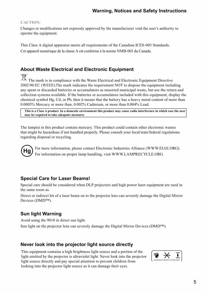
Never look into the projector light source directlyThis equipment contains a high brightness light source and a portion of the light emitted by the projector is ultraviolet light. Never look into the projector light source directly and pay special attention to prevent children from looking into the projector light source as it can damage their eyes.
AVOID EYE CONTACT TO THE LIGHT
6
Warning, Notices and Safety Instructions
CAUTION
RISK OF ELECTRIC SHOCKDO NOT OPEN
The lightning flash with an arrowhead within a triangleis intended to tell the user that inside this productmay cause risk of electrical shock to persons.
The exclamation point within a triangle is intended to tellthe user that important operating and/or servicing instructionsare included in the technical documentation for this equipment.
CAUTION / TO REDUCE THE RISK OF ELECTRIC SHOCKDO NOT REMOVE COVER(OR BACK)
NO USER-SERVICEABLE PARTS INSIDEREFER SERVICING TO QUALIFIED SERVICE PERSONNEL
Do not turn off the projector by unplugging the power cord.Under normal operations, be sure to use the SOFT POWER button to turn off the projector. And as such, avoid shutting off AC power to turn off the projector since it could lead to lamp malfunctioning or damage.
Electric shockTo protect your projector, avoid turning on the projector during lightning storms and unplug it from the wall outlet. This will prevent sudden electrical surges caused by the lightning from damaging the projector.
Do not overload wall outlets/extension cordsPay attention to the current load of the outlet you are using, be it wall outlet or extension cord outlet to ���%�� ��� �� ������� ������
CleaningWhen cleaning the projector, be sure to unplug it from the wall outlet to prevent electric shock.Do not use liquid or aerosol cleaners. Use a dry/damp cloth with excessive moisture removed for cleaning. Be sure to use cleaning cloth designed to clean monitors for the projector to prevent damages to the projector casing due to abrasion.
Dampness, smoke, steam, dust, high temperature and direct exposure to sunlightDo not operate the projector in environments where it could be expose to dampness, smoke, steam, dust, high temperature or direct sunlight. For example: bathroom, kitchen, adjacent to washing machine, damp basement rooms, electric heaters or similar environments. Keeping or operating the projector in the above-mentioned environment could lead to discoloration, mold formation, grease or damages to the projector.
7
Warning, Notices and Safety Instructions
VentilationThe projector case is designed with slots and openings to remove the heat inside the projector so that it will not overheat and damage the components. Be sure to operate the projector in an environment with ideal ventilation and don't operate it on a sofa, rug or other closed-in environments that could obstruct ventilation.
Filter <�� ���� � ���� �� ������ �� ���� ���� � �� ��=����� � ���� �� �� ���� ���� �� ���> �� ���%�� �����&�� �%�� �������� ����� �� �� �������� ��� � �� ���� �� ����� ����� ����� � ��� ?? ��� ����� �� ���� ��������� ����������
Intrusion of foreign objectsBe sure to keep all foreign objects away from entering the projector because it could be exposed to �@����� %����� �� ���� ��� � ���� ������� J��� ����� �� ��� ��� � ��� �@�� �� ������� shock. Examples of foreign objects include: cockroach, screws, liquid and so forth.In addition, never spill liquid into the projector.
Carrying the projectorWhen moving the projector on a cart, be sure to handle the cart with care as abrupt stops, jolts of excessive force or uneven ground could lead the projector to topple.
Please install the projector on an even and stable surfaceAvoid placing the projector on unstable cart, tripod, table and so forth to prevent the projector from falling, becoming damaged or causing injuries.
ServicingShould you encounter problem with the projector, please seek assistance from your local dealer or =������ ���%��� ���������� Q� �� ��� � ���%��� �� �������� "������� �� � "�� ����� �� &� exposed to high voltage or other potential hazards.Should you encounter any of the following situation, please unplug your projector from the wall outlet �� ���� =������ ���%��� ��������� ��� �������X
# Damaged power cord or power plug.# If a foreign object has fallen into the projector or if you have spilled water or other liquid into the
projector.# If the projector has been dropped accidentally or damaged.# If you experience noticeably poor performance or malfunctioning with the projector despite having
followed instructions for normal operation.
8
Warning, Notices and Safety Instructions
Changing partsShould any part of the projector be damaged, check with your servicing personnel that only ��������� ������� ��� ���� ���� ��� ���������� [��� �� ���\������� ��� �" ����� �� ����� � �� �������� �� �@��� ���� � ��� �� ������� ������ ]��� ������� ���> &� ���� � remind the servicing personnel to perform safety inspections to ensure that the projector operates normally.
Power cordDon't place the projector where the cord can be walked on. This may result in fraying or damage to the power cord, especially at the plug and the point of connection between the power cord and the projector.����� ��� �� ����� ���� � ����� ��� �� �������� �� �� "�� �� ����� ���� �������� ��� the projector (refer to the descriptions printed on the power cord). If you are not sure of the power available at the region you are in, consult your local power company to prevent damages to the �������� ��� � �� ��� �� ����� ����� ���� �� ������ ��� �@��� ��� � ������ �%������Depending on the country and region you are in, the voltage and type of socket of the wall outlet may &� �������� ���� �� ��������� �� "�� �� ��&�� � � �� ����� ���� ��� �� ��� ����> ���� "��� ���� ����� �� �� �� ����%� �� �$� ��� �� �� ����� ���� � �����&�" � � � �� ����� �� ���� of your own safety.
Notices you should read prior to the installation of the projectorSafety issues related to the lampThe lamp used in this projector contains mercury. Should the lamp be broken, please be careful when handling the glass shards and keep the surrounding environment well ventilated. Be sure to wear a mask that offers adequate protection before cleaning up to prevent inhaling mercury vapor that could cause bodily harm. For instructions on lamp replacement, refer to " Page 7 : Lamp replacement ".
Take frequent breaks to let your eyes rest Prolonged viewing of the projector screen could strain your eyes. Please be sure to rest your eyes adequately.
Installation environment for the projectorYou should avoid installing the projector at place of excessive dampness, dust or smoke. If installation in such environment is unavoidable, be sure to have the interior of the projector cleaned routinely to prolong the projector's lifecycle. Cleaning of the projector's interior should only be ��������� &" =������ ���%��� ��������� �������� &" "��� ���� ����� �� "�� ������ �� ��� to clean the inside of the projector by yourself. If other light source is directly projected onto the projector screen, the color of the image from the projector will appear to be pale and the image quality will be lower. In addition, your eyes would be more prone to fatigue. Therefore, it is recommended that the projector be installed in places without direct exposure to sunlight or other sources of intense light.The ideal operating temperature range for the projector is between 0°C ~ 40°C (32°F ~ 104°F)
The ideal storage temperature range for the projector is between -20ºC ~ 60°C (-4°F ~ 140°F)
9
Warning, Notices and Safety Instructions
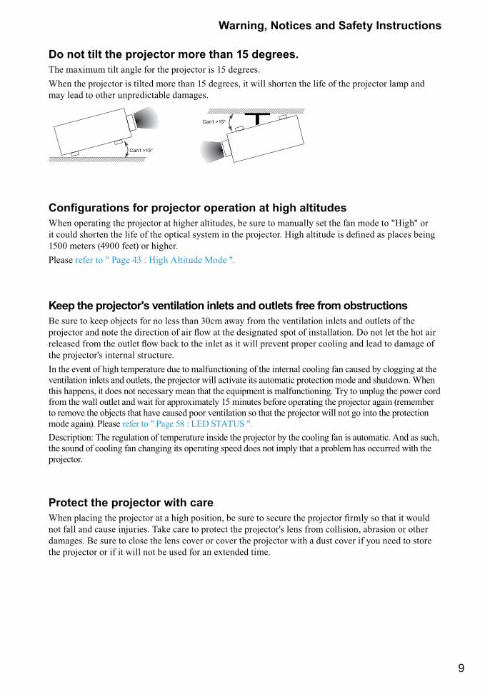
Do not tilt the projector more than 15 degrees.The maximum tilt angle for the projector is 15 degrees. When the projector is tilted more than 15 degrees, it will shorten the life of the projector lamp and may lead to other unpredictable damages.
Can’t >15°
Can’t >15°
����������� ��� �������� ������� ���� ������When operating the projector at higher altitudes, be sure to manually set the fan mode to "High" or � ����� ������ �� ���� �� �� ����� �"��� �� �� ��������� _��� ����� �� ������ � ����� &���� 1500 meters (4900 feet) or higher. Please refer to " Page 43 : High Altitude Mode ".
Keep the projector's ventilation inlets and outlets free from obstructionsBe sure to keep objects for no less than 30cm away from the ventilation inlets and outlets of the �������� �� ��� �� �������� �� �� `�� �� �������� ��� �� ��������� Q� �� �� �� �� �� ������� ���� �� ���� `�� &�� � �� ���� � � ���� ���%�� ������ ������� �� ��� � ���� �� the projector's internal structure.In the event of high temperature due to malfunctioning of the internal cooling fan caused by clogging at the ventilation inlets and outlets, the projector will activate its automatic protection mode and shutdown. When this happens, it does not necessary mean that the equipment is malfunctioning. Try to unplug the power cord from the wall outlet and wait for approximately 15 minutes before operating the projector again (remember to remove the objects that have caused poor ventilation so that the projector will not go into the protection mode again). Please refer to " Page 58 : LED STATUS ".Description: The regulation of temperature inside the projector by the cooling fan is automatic. And as such, the sound of cooling fan changing its operating speed does not imply that a problem has occurred with the projector.
Protect the projector with care{��� ������ �� �������� ���� �������> &� ���� � ������ �� �������� ����" �� � � ����� not fall and cause injuries. Take care to protect the projector's lens from collision, abrasion or other damages. Be sure to close the lens cover or cover the projector with a dust cover if you need to store the projector or if it will not be used for an extended time.
10
Warning, Notices and Safety Instructions
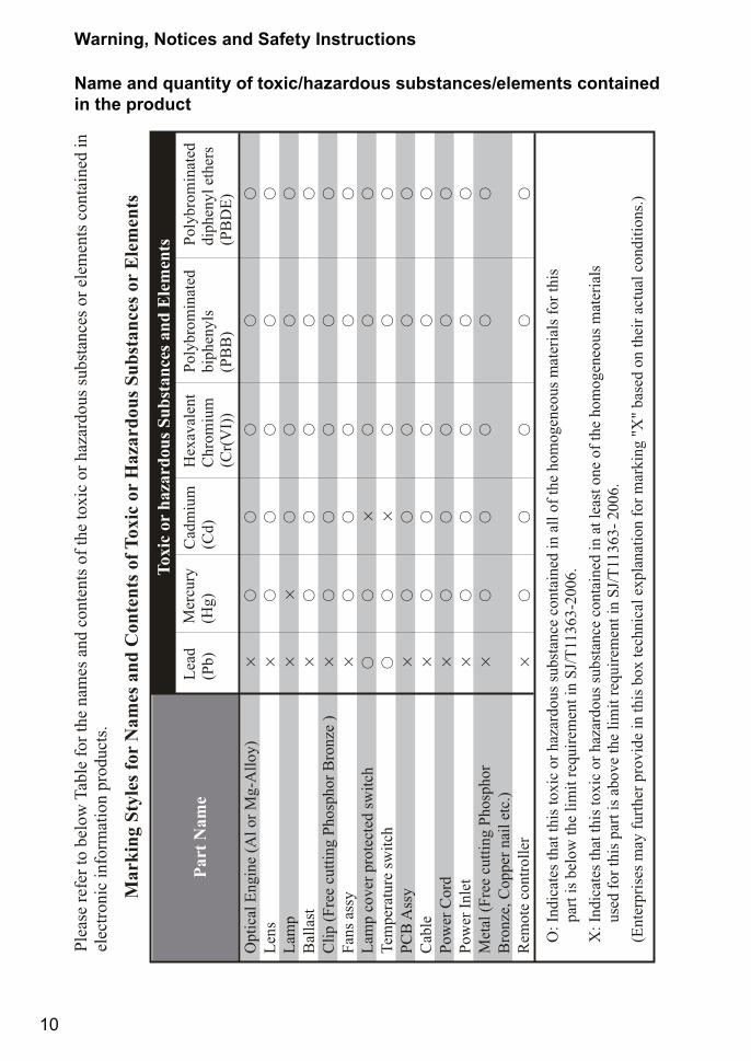
Name and quantity of toxic/hazardous substances/elements contained in the product
11
Projector parts and functions
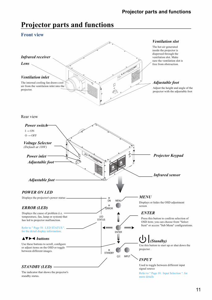
Projector parts and functionsFront view
LensInfrared receiver
Adjustable footAdjust the height and angle of the projector with the adjustable foot
Ventilation inletThe internal cooling fan draws cool air from the ventilation inlet into the projector.
Ventilation slotThe hot air generated inside the projector is dispersed through the ventilation slot. Make sure the ventilation slot is free from obstruction.
Rear view
LEDSTATUS
ENTER
INPUT
ERROR
MENUON
STANDBY
INPUT Used to toggle between different input signal sourceRefer to “ Page 10 : Input Selection “. for more details
MENUDisplays or hides the OSD adjustment screen
(Standby) Use this button to start up or shut down the projector .
STANDBY (LED)The indicator that shows the projector's standby status.
Voltage Selector(Default at 110V)
Refer to " Page 58 : LED STATUS ". for the detail display information.
ERROR (LED)Displays the cause of problem (i.e. temperature, fan, lamp or system) that has led to projector malfunction.
�� � � buttons[�� ���� &���� � ������> �������� or adjust items on the OSD or toggle between different images.
POWER ON LEDDisplays the projector's power status
ENTER����� ��� &��� � ������ �������� �� OSD item; you can choose from "Select ���} �� ����� }��& <���} ������������
Adjustable foot
Adjustable foot
Infrared sensor
Power inlet Projector Keypad
Power switch� � ��� � ���
12
Projector parts and functions
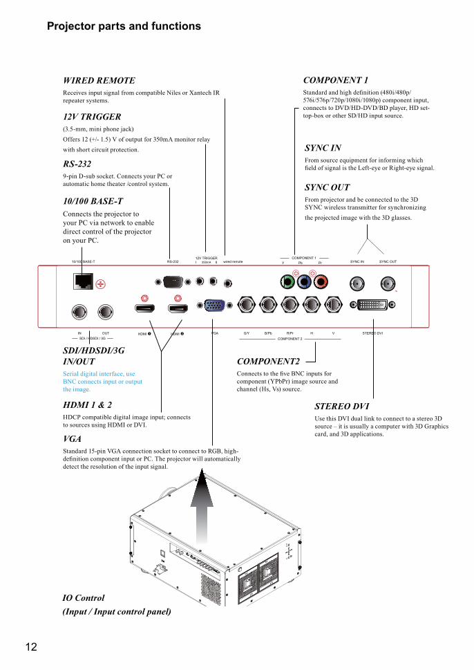
10/100 BASE-TConnects the projector to your PC via network to enable direct control of the projector on your PC.
COMPONENT 1Y Pb Pr10/100 BASE-T RS-232 wired remote
12V TRIGGERI II350mA SYNC IN SYNC OUT
IN OUTSDI / HDSDI / 3G COMPONENT 2
G/Y B/Pb R/Pr H VVGAHDMI � HDMI � STEREO DVI
RS-2329-pin D-sub socket. Connects your PC or automatic home theater /control system.
HDMI 1 & 2HDCP compatible digital image input; connects to sources using HDMI or DVI.
SDI/HDSDI/3G IN/OUTSerial digital interface, use BNC connects input or output the image.
SYNC INFrom source equipment for informing which ���� �� ����� �� �� ���\�"� �� ����\�"� ������
SYNC OUTFrom projector and be connected to the 3D SYNC wireless transmitter for synchronizing the projected image with the 3D glasses.
12V TRIGGER(3.5-mm, mini phone jack)Offers 12 (+/- 1.5) V of output for 350mA monitor relay with short circuit protection.
VGAStandard 15-pin VGA connection socket to connect to RGB, high-�������� �������� ���� �� ��� J�� �������� ���� �������" detect the resolution of the input signal.
WIRED REMOTEReceives input signal from compatible Niles or Xantech IR repeater systems.
COMPONENT 1����� �� ���� �������� ����������� 576i/576p/720p/1080i/1080p) component input, connects to DVD/HD-DVD/BD player, HD set-top-box or other SD/HD input source.
COMPONENT2������� � �� �%� ��� ����� ��� component (YPbPr) image source and channel (Hs, Vs) source.
IO Control(Input / Input control panel)
STEREO DVIUse this DVI dual link to connect to a stereo 3D source – it is usually a computer with 3D Graphics card, and 3D applications.
13
Projector parts and functions
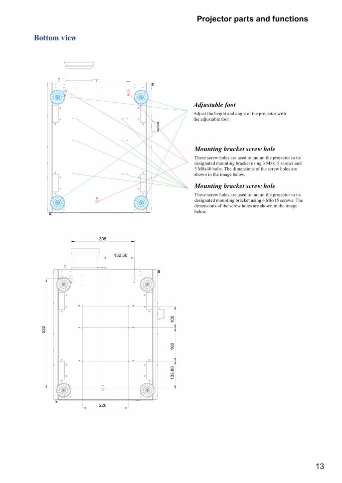
Bottom view
Adjustable footAdjust the height and angle of the projector with the adjustable foot
Mounting bracket screw holeThese screw holes are used to mount the projector to its designated mounting bracket using 3 M8x15 screws and 3 M8x40 bolts. The dimensions of the screw holes are shown in the image below.
Mounting bracket screw holeThese screw holes are used to mount the projector to its designated mounting bracket using 6 M6x15 screws. The dimensions of the screw holes are shown in the image below.
14
Projector parts and functions
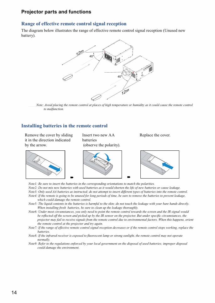
Range of effective remote control signal receptionThe diagram below illustrates the range of effective remote control signal reception (Unused new battery).
40°
12m
12m40°
Note: Avoid placing the remote control at places of high temperature or humidity as it could cause the remote control to malfunction.
Installing batteries in the remote control
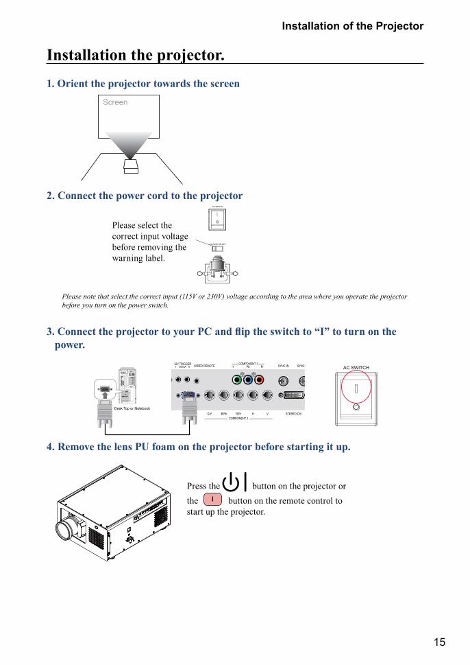
Remove the cover by sliding it in the direction indicated by the arrow.
Insert two new AA batteries (observe the polarity).
Replace the cover.
� �Note1: Be sure to insert the batteries in the corresponding orientations to match the polarities.Note2: Do not mix new batteries with used batteries as it would shorten the life of new batteries or cause leakage.Note3: Only used AA batteries as instructed; do not attempt to insert different types of batteries into the remote control.Note4: If the remote is going to be unused for long periods of time, be sure to remove the batteries to prevent leakage,
which could damage the remote control.Note5: The liquid contents in the batteries is harmful to the skin; do not touch the leakage with your bare hands directly.
When installing fresh batteries, be sure to clean up the leakage thoroughly.Note6: Under most circumstances, you only need to point the remote control towards the screen and the IR signal would
������������������ ���������������������������� �� �������������������������� ������������� ����� ��������������������������������� ����� �������������������������������������������� ��!������� ������� ����������������������������������������������������
Note7: If the range of effective remote control signal reception decreases or if the remote control stops working, replace the batteries.
"��#$��������������������������� ��%� �������� ������������ ����� ���������������������������������������normally.
Note9: Refer to the regulations enforced by your local government on the disposal of used batteries; improper disposal could damage the environment.
15
Installation of the Projector
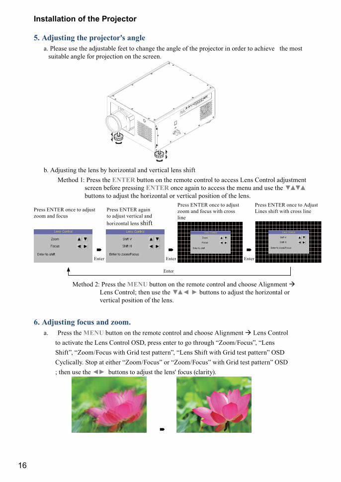
Installation the projector.1. Orient the projector towards the screen
Screen
2. Connect the power cord to the projector
AC SWITCH
VOLTAGE SELECT
Please select the correct input voltage before removing the warning label.
&��� ����������� �����������������������'**+-���/8<-=���������������������������>���������������������������before you turn on the power switch.
�������������� ���� ������ ����������������������$%&���� ��������power.
COMPONENT 2SDI / HDSDI / 3G
COMPONENT 1Y Pb Pr10/100 BASE-T RS-232 WIRED REMOTE12V TRIGGER
I II350mA SYNC IN SYNC
IN OUT G/Y B/Pb R/Pr H VVGAHDMI � HDMI � STEREO DVI
�Desk Top or Notebook
AC SWITCH
4. Remove the lens PU foam on the projector before starting it up.
Press the button on the projector or the l button on the remote control to start up the projector.
16
Installation of the Projector
5. Adjusting the projector's angle a. Please use the adjustable feet to change the angle of the projector in order to achieve the most
suitable angle for projection on the screen.
b. Adjusting the lens by horizontal and vertical lens shift Method 1: Press the ENTER button on the remote control to access Lens Control adjustment
screen before pressing ENTER once again to access the menu and use the ()() buttons to adjust the horizontal or vertical position of the lens.
Press ENTER once to adjust zoom and focus
Press ENTER once to adjust zoom and focus with cross line
Press ENTER once to Adjust Lines shift with cross line
�Enter
Enter
�Enter
�Enter
Press ENTER again to adjust vertical and horizontal lens shift
Method 2: Press the MENU button on the remote control and choose Alignment � Lens Control; then use the () ) ( buttons to adjust the horizontal or vertical position of the lens.
6. Adjusting focus and zoom. a. Press the MENU button on the remote control and choose Alignment � Lens Control to activate the Lens Control OSD, press enter to go through “Zoom/Focus”, “Lens Shift”, “Zoom/Focus with Grid test pattern”, “Lens Shift with Grid test pattern” OSD Cyclically. Stop at either “Zoom/Focus” or “Zoom/Focus” with Grid test pattern” OSD ; then use the *+ buttons to adjust the lens' focus (clarity).
�
17
Installation of the Projector
b. Press the MENU button on the remote control and choose Alignment � Lens Control to activate the Lens Control OSD, press enter to go through "Zoom/Focus", "Lens Shift", "Zoom/Focus with Grid test pattern", "Lens Shift with Grid test pattern" OSD Cyclically. Stop at either "Zoom/Focus" or "Zoom/Focus" with Grid test pattern" OSD; then use the () buttons to adjust the size of the image that is projected onto the screen.
Original image size Zoom out Zoom in
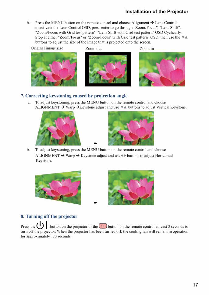
7. Correcting keystoning caused by projection angle a. To adjust keystoning, press the MENU button on the remote control and choose
ALIGNMENT � Warp �Keystone adjust and use () buttons to adjust Vertical Keystone.
� b. To adjust keystoning, press the MENU button on the remote control and choose ALIGNMENT � Warp � Keystone adjust and use ) ( buttons to adjust Horizontal Keystone.
�
8. Turning off the projector
Press the button on the projector or the button on the remote control at least 3 seconds to turn off the projector. When the projector has been turned off, the cooling fan will remain in operation for approximately 170 seconds.
18
Installation of the Projector
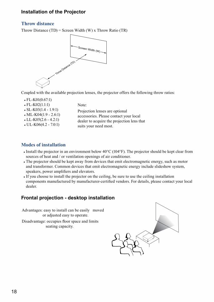
Throw distanceThrow Distance (TD) = Screen Width (W) x Throw Ratio (TR)
Screen Width (W)
Throw Distance (TD)
Coupled with the available projection lenses, the projector offers the following throw ratios:
# FL-K01(0.67:1)# FL-K02(1.1:1)# SL-K03(1.4 - 1.9:1)# ML-K04(1.9 - 2.6:1)# LL-K05(2.6 - 4.2:1)# UL-K06(4.2 - 7.0:1)
Note:Projection lenses are optional accessories. Please contact your local dealer to acquire the projection lens that suits your need most.
Modes of installation# Install the projector in an environment below 40°C (104°F). The projector should be kept clear from
sources of heat and / or ventilation openings of air conditioner.# The projector should be kept away from devices that emit electromagnetic energy, such as motor
and transformer. Common devices that emit electromagnetic energy include slideshow system, �������> ����� �������� �� ���%����
# If you choose to install the projector on the ceiling, be sure to use the ceiling installation ��������� ��������� &" ���������\������� %������� ��� �����> ����� ���� "��� ���� dealer.
Frontal projection - desktop installation
Advantages: easy to install can be easily moved or adjusted easy to operate.
Q���%���X �������� `��� ���� �� ����� seating capacity.
19
Installation of the Projector
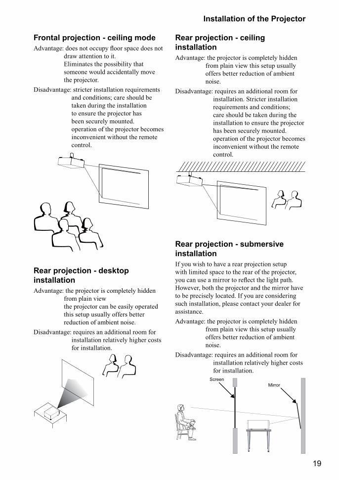
Frontal projection - ceiling mode]�%���X ���� �� �����" `��� ���� ���� ��
draw attention to it. Eliminates the possibility that someone would accidentally move the projector.
Disadvantage: stricter installation requirements and conditions; care should be taken during the installation to ensure the projector has been securely mounted. operation of the projector becomes inconvenient without the remote control.
Rear projection - desktop installation Advantage: the projector is completely hidden
from plain view the projector can be easily operated this setup usually offers better reduction of ambient noise.
Disadvantage: requires an additional room for installation relatively higher costs for installation.
Rear projection - ceiling installationAdvantage: the projector is completely hidden
from plain view this setup usually offers better reduction of ambient noise.
Disadvantage: requires an additional room for installation. Stricter installation requirements and conditions; care should be taken during the installation to ensure the projector has been securely mounted. operation of the projector becomes inconvenient without the remote control.
Rear projection - submersive installationIf you wish to have a rear projection setup with limited space to the rear of the projector, "�� �� ��� ������ � ��`�� �� ���� ��� However, both the projector and the mirror have to be precisely located. If you are considering such installation, please contact your dealer for assistance.Advantage: the projector is completely hidden
from plain view this setup usually offers better reduction of ambient noise.
Disadvantage: requires an additional room for installation relatively higher costs for installation.
ScreenMirror
20
Installation of the Projector
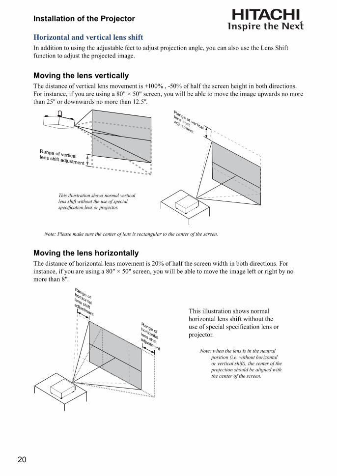
Horizontal and vertical lens shiftIn addition to using the adjustable feet to adjust projection angle, you can also use the Lens Shift function to adjust the projected image.
Moving the lens verticallyThe distance of vertical lens movement is +100% , -50% of half the screen height in both directions. For instance, if you are using a 80" × 50" screen, you will be able to move the image upwards no more than 25'' or downwards no more than 12.5''.
Range of verticallens shift adjustment
Range of vertical
lens shiftadjustment
This illustration shows normal vertical lens shift without the use of special �������������� �����������
Note: Please make sure the center of lens is rectangular to the center of the screen.
Moving the lens horizontallyThe distance of horizontal lens movement is 20% of half the screen width in both directions. For instance, if you are using a 80" × 50" screen, you will be able to move the image left or right by no more than 8".
Range ofhorizontallens shiftadjustment
Range ofhorizontallens shiftadjustment
This illustration shows normal horizontal lens shift without the ��� �� ������ ���������� ���� �� projector.
Note: when the lens is in the neutral position (i.e. without horizontal or vertical shift), the center of the ��������� ��������������>����the center of the screen.
21
Installation of the Projector
Connecting the projector to other devices
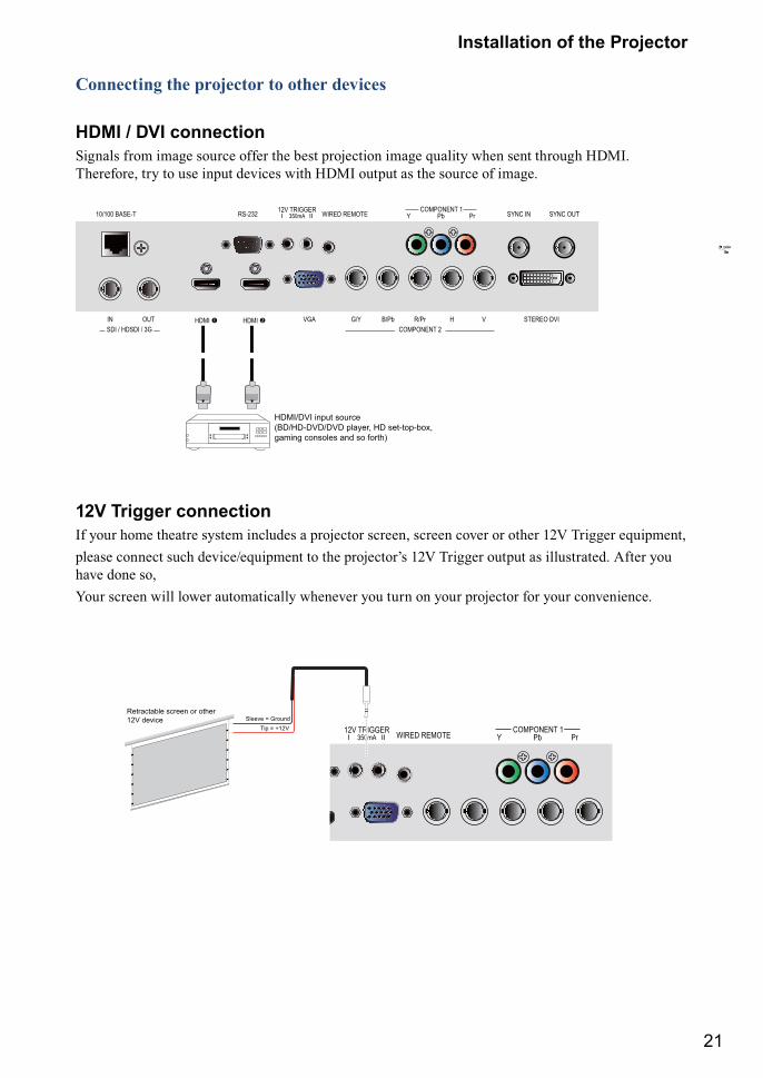
HDMI / DVI connectionSignals from image source offer the best projection image quality when sent through HDMI. Therefore, try to use input devices with HDMI output as the source of image.
COMPONENT 2SDI / HDSDI / 3G
COMPONENT 1Y Pb Pr10/100 BASE-T RS-232 WIRED REMOTE12V TRIGGER
I II350mA SYNC IN SYNC OUT
IN OUT G/Y B/Pb R/Pr H VVGAHDMI � HDMI � STEREO DVI
HDMI/DVI input source(BD/HD-DVD/DVD player, HD set-top-box, gaming consoles and so forth)
12V Trigger connectionIf your home theatre system includes a projector screen, screen cover or other 12V Trigger equipment,����� ������ ���� ��%�����=������ � �� ��������+� ��� J������ ���� � ��������� ]��� "�� have done so, Your screen will lower automatically whenever you turn on your projector for your convenience.
COMPONENT 1Y Pb Pr10/100 BASE-T RS-232 WIRED REMOTE12V TRIGGER
I II350mATip = +12V
Sleeve = Ground Retractable screen or other 12V device
COMPONENT 2SDI / HDSDI / 3G
COMPONENT 1Y Pb Pr10/100 BASE-T RS-232 WIRED REMOTE12V TRIGGERI II350mA SYNC IN SYNC OUT
IN OUT G/Y B/Pb R/Pr H VVGAHDMI � HDMI � STEREO DVI
AC MAINS100-240 Volts
AC SWITCH
�Desk Top or Notebook
連接至牆壁插座
22
Installation of the Projector
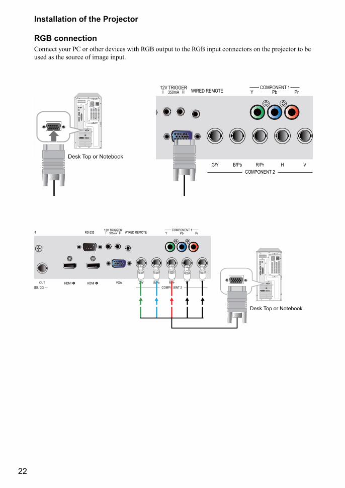
RGB connectionConnect your PC or other devices with RGB output to the RGB input connectors on the projector to be used as the source of image input.
COMPONENT 2SDI / HDSDI / 3G
COMPONENT 1Y Pb Pr0/100 BASE-T RS-232 WIRED REMOTE12V TRIGGER
I II350mA
IN OUT G/Y B/Pb R/Pr H VVGAHDMI � HDMI �
�Desk Top or Notebook
COMPONENT 2SDI / 3G
COMPONENT 1Y Pb Pr-T RS-232 WIRED REMOTE12V TRIGGER
I II350mA SYNC IN SYNC OUT
OUT G/Y B/Pb R/Pr H VVGAHDMI � HDMI � STEREO DVI
G/Y B/Pb R/Pr H V
Desk Top or Notebook
23
Installation of the Projector
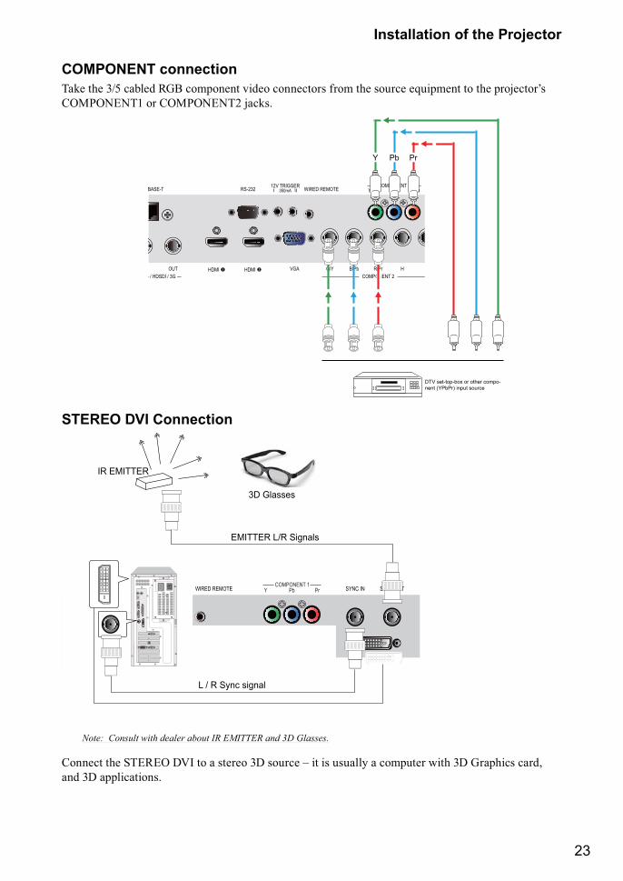
COMPONENT connectionJ�� �� ��? �&��� ��� �������� %���� ��������� ���� �� ������ �=������ � �� ��������+� COMPONENT1 or COMPONENT2 jacks.
COMPONENT 2 / HDSDI / 3G
COMPONENT 1Y Pb PrBASE-T RS-232 WIRED REMOTE12V TRIGGER
I II350mA SYNC IN SYNC OUT
OUT G/Y B/Pb R/Pr H VVGAHDMI � HDMI � STEREO DVI
DTV (YPbPr)
Y Pb Pr
DTV set-top-box or other compo-nent (YPbPr) input source
STEREO DVI Connection
COMPONENT 2
COMPONENT 1Y Pb PrRS-232 WIRED REMOTE12V TRIGGER
I II350mA SYNC IN SYNC OUT
G/Y B/Pb R/Pr H VVGAHDMI � HDMI � STEREO DVI
IR EMITTER
3D Glasses
L / R Sync signal
EMITTER L/R Signals
Note: Consult with dealer about IR EMITTER and 3D Glasses.
Connect the STEREO DVI to a stereo 3D source – it is usually a computer with 3D Graphics card, and 3D applications.
24
Installation of the Projector
3D modeThere are few ways to go to the 3D mode
# OSD menu: Go to Main Menu “Input > Input Selection”, and select STEREO DVI# Remote control: Press hot key “5” to go to STEREO DVI directly# Network Webpage: Go to “Source/general” > “Source” and select STEREO DVI# RS232 Commands : Use “ Input Selection” to select STEREO DVI
When this function is blanking. The 3D Mode is not available
2D modePlease note that OSD menu is not available in 3D mode. The ways to switch back to 2D mode are:
# Remote control: Press any of the input key 1-4 will switch back to 2D mode.# Network Webpage: Go to “Source/general” > “Source” and select any other source that are
available. # RS232 Commands: Use “ Input Selection” to select any other source that are available.
Turning on the projectorRefer to the instructions covered in “ Page 15 : Installation the projector. “.
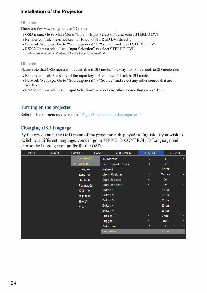
Changing OSD languageBy factory default, the OSD menu of the projector is displayed in English. If you wish to switch to a different language, you can go to MENU � CONTROL � Language and choose the language you prefer for the OSD.
25
Installation of the Projector
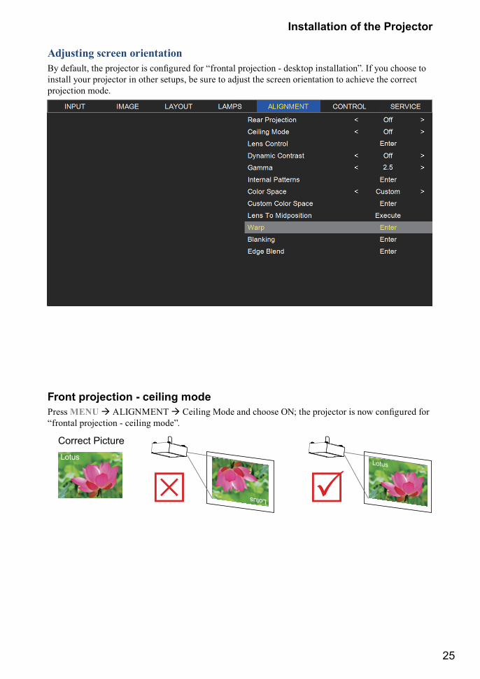
Adjusting screen orientation�" �����> �� �������� �� ��������� ��� ������ ��������� \ ������ ���������� �� "�� ������ � install your projector in other setups, be sure to adjust the screen orientation to achieve the correct projection mode.
Front projection - ceiling modePress MENU � ALIGNMENT � ������� <��� �� ������ ��� �� �������� �� ��� ��������� ��� “frontal projection - ceiling mode”.
��
Correct PictureLotus
Lotus
Lotus
26
Installation of the Projector
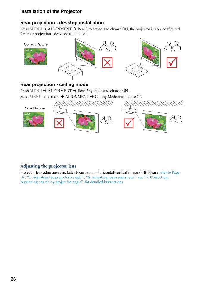
Rear projection - desktop installation Press MENU � ALIGNMENT � ��� ��������� �� ������ ��� �� �������� �� ��� ��������� for “rear projection - desktop installation”.
Lotus
�
Correct Picture Lotus
�Lotus
Rear projection - ceiling modePress MENU � ALIGNMENT � Rear Projection and choose ON; press MENU once more � ALIGNMENT � Ceiling Mode and choose ON
Lotus
��
Correct Picture
Lotus
Lotus
Adjusting the projector lensProjector lens adjustment includes focus, zoom, horizontal/vertical image shift. Please refer to Page �� X �?� ]������� �� ��������+� ������> ��� ]������� ����� �� @������ �� ��� ��������� keystoning caused by projection angle”. for detailed instructions.
27
REMOTE CONTROL
Remote control
32
4
1
5
INPUT
ASPECTRATIO
AUTO IMAGE
PAUSE TEXT
MENU
SHARPN
PHASE COLOR TINT
ADDRESSSWAPPIP
1
3
4
6
7
2
5
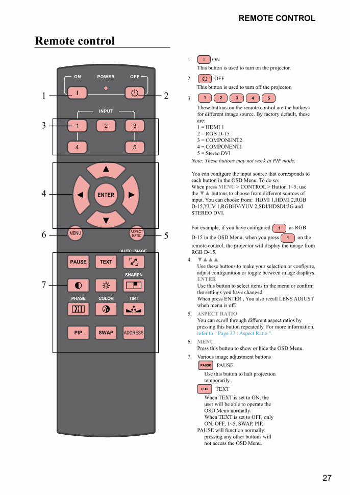
1. ON This button is used to turn on the projector.
2. OFF This button is used to turn off the projector.
3. 1 2 3 4 5
These buttons on the remote control are the hotkeys for different image source. By factory default, these are: 1 = HDMI 1 2 = RGB D-15 3 = COMPONENT2 4 = COMPONENT1 5 = Stereo DVI
Note: These buttons may not work at PIP mode.
��� �� �������� �� ���� ������ � ����������� � each button in the OSD Menu. To do so: When press MENU > CONTROL > Button 1~5; use the () buttons to choose from different sources of input. You can choose from: HDMI 1,HDMI 2,RGB D-15,YUV 1,RGBHV/YUV 2,SDI/HDSDI/3G and STEREO DVI.
��� �$����> �� "�� �%� ��������� 1 as RGB
D-15 in the OSD Menu, when you press 1 on the remote control, the projector will display the image from RGB D-15.
4. ())) [�� ���� &���� � ��� "��� �������� �� ��������> ���� ���������� �� ����� &����� ���� �����"�� ENTER [�� ��� &��� � ����� ���� �� �� ���� �� ������ the settings you have changed. When press ENTER , You also recall LENS ADJUST when menu is off.
5. ASPECT RATIO You can scroll through different aspect ratios by pressing this button repeatedly. For more information, refer to " Page 37 : Aspect Ratio ".
6. MENU Press this button to show or hide the OSD Menu.
7. Various image adjustment buttons PAUSE PAUSE
Use this button to halt projection temporarily.
TEXT TEXT When TEXT is set to ON, the user will be able to operate the OSD Menu normally. When TEXT is set to OFF, only ON, OFF, 1~5, SWAP, PIP, PAUSE will function normally; pressing any other buttons will not access the OSD Menu.
28
REMOTE CONTROL
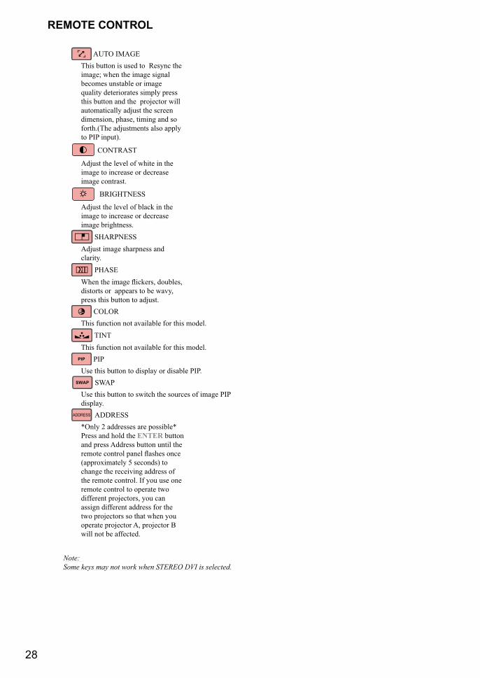
AUTO IMAGE This button is used to Resync the image; when the image signal becomes unstable or image quality deteriorates simply press this button and the projector will automatically adjust the screen dimension, phase, timing and so forth.(The adjustments also apply to PIP input).
CONTRAST
Adjust the level of white in the image to increase or decrease image contrast.
BRIGHTNESS
Adjust the level of black in the image to increase or decrease image brightness.
SHARPNESS Adjust image sharpness and clarity.
PHASE {��� �� ���� `������> ���&���> distorts or appears to be wavy, press this button to adjust.
COLOR This function not available for this model.
TINT This function not available for this model.
PIP PIP Use this button to display or disable PIP.
SWAP SWAP Use this button to switch the sources of image PIP display. ADDRESS ADDRESS *Only 2 addresses are possible* Press and hold the ENTER button and press Address button until the ����� ������ ���� `���� ���� (approximately 5 seconds) to change the receiving address of the remote control. If you use one remote control to operate two different projectors, you can assign different address for the two projectors so that when you operate projector A, projector B will not be affected.
Note: Some keys may not work when STEREO DVI is selected.
29
OSD Menu description
OSD Menu Tree
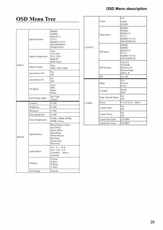
INPUT
Input Selection
HDMI1 HDMI2 RGB D-15 YUV1 RGBHV/YUV2 SDI/HDSDI/3G STEREO DVI
���� ����������
Auto YUV HD YUV STD RGB-PC RGB-Video
Input Locking Auto 48Hz, 50Hz, 60Hz
Auto Power Off On Off
Auto Power ON On Off
No Signal
Logo Blue Black White
Auto Image Adjust Off, Auto Always
IMAGE
Contrast 0~200
Brightness 0~200
Sharpness 0~200
Noise Reduction 0~200
Color Temperature 3200K, 5400K, 6500K, 9300K, Native
Input Balance
Black Balance Offset Red Offset Green Offset Blue Offset White Balance Red Gain Green Gain Blue Gain
Aspect Ratio
5:4 , 4:3, 16:10 16:9, 1.88, 2.35 Letterbox, Native, unscaled
Timings
H Total H Start H Phase V Start
Auto Image Execute
LAYOUT
ZoomOffCROP ZOOM
Main Select
HDMI1 HDMI2 RGB D-15 YUV1 RGBHV/YUV2 SDI/HDSDI/3G
PIP Select
HDMI1 HDMI2 RGB D-15 YUV1 RGBHV/YUV2 SDI/HDSDI/3G
PIP Position
Top Left Top Right Bottom Left Bottom Right Split L-R
PIP On, Off
LAMPS
ModeEco Normal Power
LAMPS Single Dual
High Altitude Mode On Off
Power 0~35 (78.3% - 100%)
Lamp1 Status On Off
Lamp2 Status On Off
Lamp1 Run Time XX HRS
Lamp2 Run Time XX HRS
30
OSD Menu description
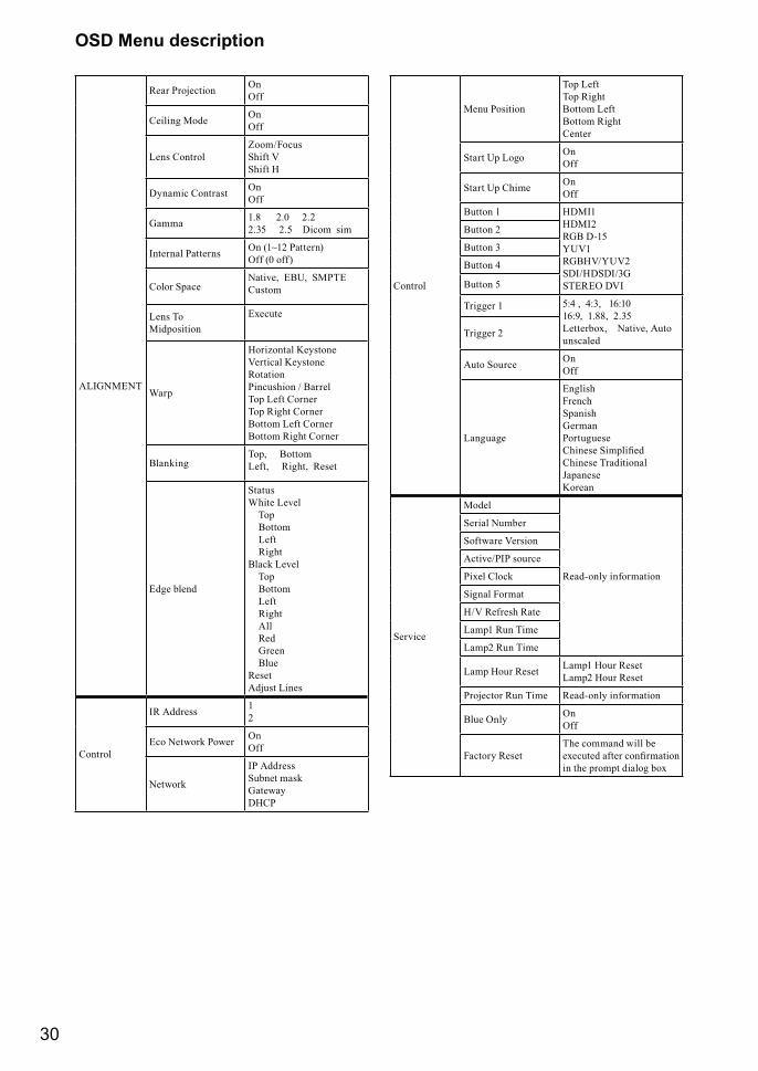
ALIGNMENT
Rear Projection On Off
Ceiling Mode On Off
Lens ControlZoom/Focus Shift V Shift H
Dynamic Contrast On Off
Gamma 1.8 2.0 2.2 2.35 2.5 Dicom sim
Internal Patterns On (1~12 Pattern) Off (0 off)
Color SpaceNative, EBU, SMPTE Custom
Lens To Midposition
Execute
Warp
Horizontal Keystone Vertical Keystone Rotation Pincushion / Barrel Top Left Corner Top Right Corner Bottom Left Corner Bottom Right Corner
BlankingTop, Bottom Left, Right, Reset
Edge blend
Status White Level Top Bottom Left Right Black Level Top Bottom Left Right All Red Green Blue Reset Adjust Lines
Control
IR Address 1 2
Eco Network Power On Off
Network
IP Address Subnet mask Gateway DHCP
Control
Menu Position
Top Left Top Right Bottom Left Bottom Right Center
Start Up Logo On Off
Start Up Chime On Off
Button 1 HDMI1 HDMI2 RGB D-15 YUV1 RGBHV/YUV2 SDI/HDSDI/3G STEREO DVI
Button 2
Button 3
Button 4
Button 5
Trigger 1 5:4 , 4:3, 16:10 16:9, 1.88, 2.35 Letterbox, Native, Auto unscaled
Trigger 2
Auto Source On Off
Language
English French Spanish German Portuguese ������� ��������� Chinese Traditional Japanese Korean
Service
Model
Read-only information
Serial Number
Software Version
Active/PIP source
Pixel Clock
Signal Format
H/V Refresh Rate
Lamp1 Run Time
Lamp2 Run Time
Lamp Hour Reset Lamp1 Hour Reset Lamp2 Hour Reset
Projector Run Time Read-only information
Blue Only On Off
Factory ResetThe command will be �$����� ��� ��������� in the prompt dialog box
31
OSD Menu description
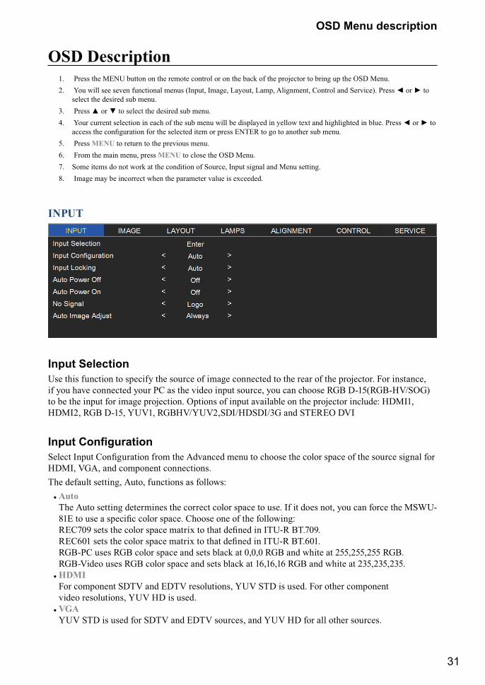
OSD Description1. Press the MENU button on the remote control or on the back of the projector to bring up the OSD Menu.2. You will see seven functional menus (Input, Image, Layout, Lamp, Alignment, Control and Service). Press * or + to
select the desired sub menu. 3. ����� � �� � � ����� �� ������� ��& ����� 4. Your current selection in each of the sub menu will be displayed in yellow text and highlighted in blue. Press * or + to
����� �� ���������� ��� �� ������� ��� �� ����� ��J�� � �� � ����� ��& �����5. Press MENU to return to the previous menu.6. From the main menu, press MENU to close the OSD Menu.7. Some items do not work at the condition of Source, Input signal and Menu setting.8. Image may be incorrect when the parameter value is exceeded.
INPUT
Input SelectionUse this function to specify the source of image connected to the rear of the projector. For instance, if you have connected your PC as the video input source, you can choose RGB D-15(RGB-HV/SOG) to be the input for image projection. Options of input available on the projector include: HDMI1, HDMI2, RGB D-15, YUV1, RGBHV/YUV2,SDI/HDSDI/3G and STEREO DVI
���� ��������������� ���� ���������� ���� �� ]�%���� ���� � ������ �� ����� ���� �� �� ������ ����� ��� HDMI, VGA, and component connections.The default setting, Auto, functions as follows:
# Auto The Auto setting determines the correct color space to use. If it does not, you can force the MSWU-��� � ��� ������� ����� ����� ������ ��� �� �� ���������X ������ ��� �� ����� ���� ���$ � � ������ �� �J[\� �J����� ������ ��� �� ����� ���� ���$ � � ������ �� �J[\� �J����� RGB-PC uses RGB color space and sets black at 0,0,0 RGB and white at 255,255,255 RGB. RGB-Video uses RGB color space and sets black at 16,16,16 RGB and white at 235,235,235.
# HDMI For component SDTV and EDTV resolutions, YUV STD is used. For other component video resolutions, YUV HD is used.
# VGA YUV STD is used for SDTV and EDTV sources, and YUV HD for all other sources.
32
OSD Menu description
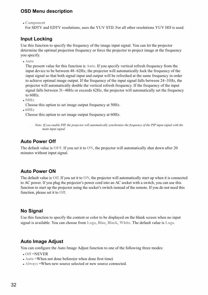
# Component For SDTV and EDTV resolutions, uses the YUV STD. For all other resolutions YUV HD is used.
Input LockingUse this function to specify the frequency of the image input signal. You can let the projector determine the optimal projection frequency or force the projector to project image at the frequency you specify.
# Auto The present value for this function is Auto. If you specify vertical refresh frequency from the input device to be between 48~62Hz, the projector will automatically lock the frequency of the input signal so that both signal input and output will be refreshed at the same frequency in order to achieve optimal image output. If the frequency of the input signal falls between 24~31Hz, the projector will automatically double the vertical refresh frequency. If the frequency of the input signal falls between 31~48Hz or exceeds 62Hz, the projector will automatically set the frequency to 60Hz.
# 50Hz Choose this option to set image output frequency at 50Hz.
# 60Hz Choose this option to set image output frequency at 60Hz.
� "��$���������������&�&��������������>����������������� �������?���������@������������&�&������� ������>��������
main input signal.
Auto Power OffThe default value is OFF. If you set it to ON, the projector will automatically shut down after 20 minutes without input signal.
Auto Power ONThe default value is Off. If you set it to ON, the projector will automatically start up when it is connected � ]� ������ �� "�� ���� �� ��������+� ����� ���� ��� � ]� ����� ��� �����> "�� �� ��� ��� ������� � �� �� �� �������� ����� �� �����+� ����� ����� �� �� ������ �� "�u do not need this function, please set it to Off.
No SignalUse this function to specify the content or color to be displayed on the blank screen when no input signal is available. You can choose from Logo, Blue, Black, White. The default value is Logo.
Auto Image Adjust��� �� �������� �� ]�� ���� ]���� ������� � ��� �� �� ��������� ���� �����X
# Off =NEVER # Auto {��� �� ���� &�������� ���� ���� ��� ���¡# Always =When new source selected or new source connected.
33
OSD Menu description
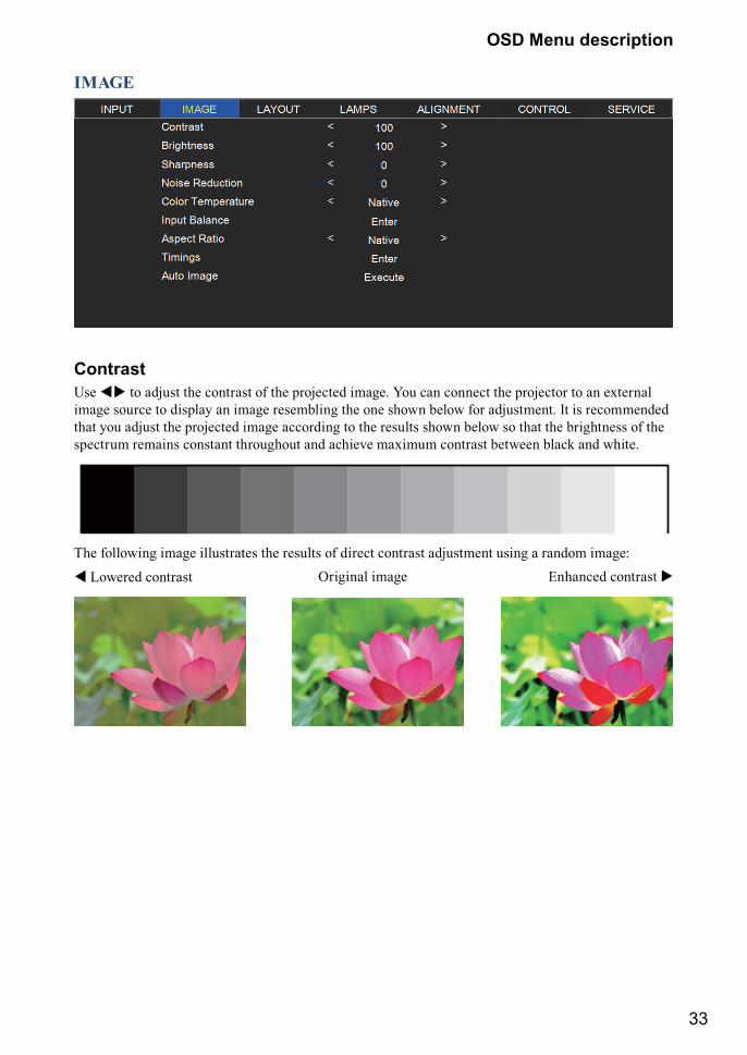
IMAGE
ContrastUse �� to adjust the contrast of the projected image. You can connect the projector to an external image source to display an image resembling the one shown below for adjustment. It is recommended that you adjust the projected image according to the results shown below so that the brightness of the spectrum remains constant throughout and achieve maximum contrast between black and white.
The following image illustrates the results of direct contrast adjustment using a random image:
� Lowered contrast Enhanced contrast �Original image
34
OSD Menu description
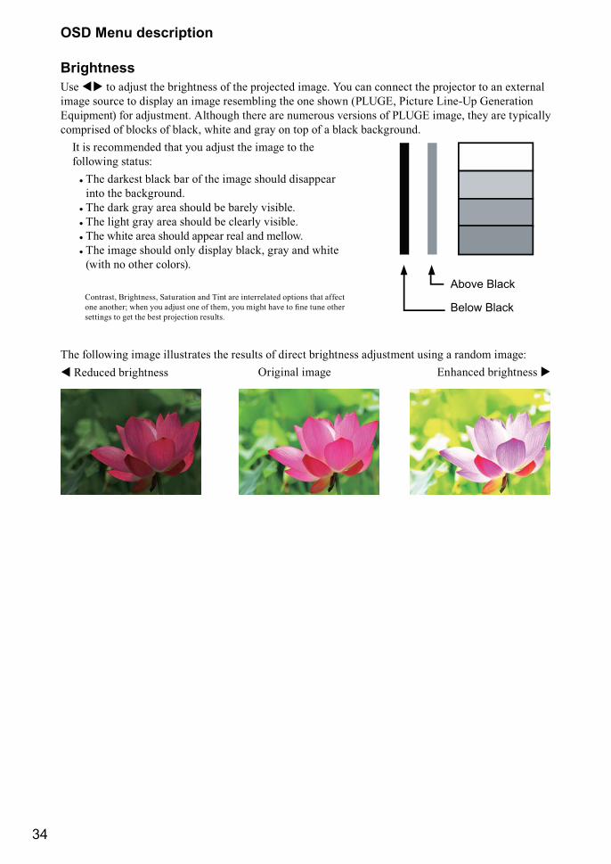
BrightnessUse �� to adjust the brightness of the projected image. You can connect the projector to an external image source to display an image resembling the one shown (PLUGE, Picture Line-Up Generation Equipment) for adjustment. Although there are numerous versions of PLUGE image, they are typically comprised of blocks of black, white and gray on top of a black background.
Contrast, Brightness, Saturation and Tint are interrelated options that affect ��� ������ ���� "�� ���� ��� �� ���> "�� ���� �%� � ��� ��� ���� settings to get the best projection results.
Above Black
Below Black
It is recommended that you adjust the image to the following status:
# The darkest black bar of the image should disappear into the background.
# The dark gray area should be barely visible.# The light gray area should be clearly visible.# The white area should appear real and mellow.# The image should only display black, gray and white
(with no other colors).
The following image illustrates the results of direct brightness adjustment using a random image: � Reduced brightness Enhanced brightness �Original image
35
OSD Menu description
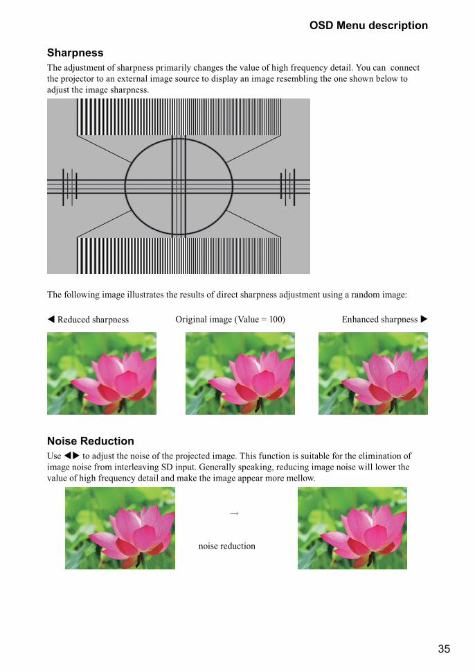
SharpnessThe adjustment of sharpness primarily changes the value of high frequency detail. You can connect the projector to an external image source to display an image resembling the one shown below to adjust the image sharpness.
The following image illustrates the results of direct sharpness adjustment using a random image: � Reduced sharpness Enhanced sharpness �Original image (Value = 100)
Noise ReductionUse �� to adjust the noise of the projected image. This function is suitable for the elimination of image noise from interleaving SD input. Generally speaking, reducing image noise will lower the value of high frequency detail and make the image appear more mellow.
�
noise reduction
36
OSD Menu description
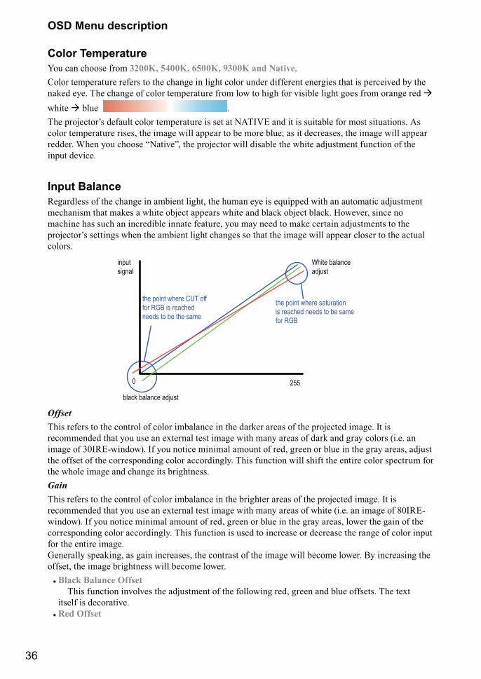
Color TemperatureYou can choose from 3200K, 5400K, 6500K, 9300K and Native.Color temperature refers to the change in light color under different energies that is perceived by the naked eye. The change of color temperature from low to high for visible light goes from orange red � white � blue .J�� ��������+� ����� ����� �������� �� �� �]J��� �� � �� ���&�� ��� ��� �������� ]� color temperature rises, the image will appear to be more blue; as it decreases, the image will appear redder. When you choose “Native”, the projector will disable the white adjustment function of the input device.
Input BalanceRegardless of the change in ambient light, the human eye is equipped with an automatic adjustment mechanism that makes a white object appears white and black object black. However, since no machine has such an incredible innate feature, you may need to make certain adjustments to the ��������+� ������ ���� �� �&��� ���� ������ �� � �� ���� ���� ���� ������ � �� ��� colors.
the point where saturationis reached needs to be samefor RGB
the point where CUT off for RGB is reached needs to be the same
White balanceadjust
black balance adjust
inputsignal
0 255
OffsetThis refers to the control of color imbalance in the darker areas of the projected image. It is recommended that you use an external test image with many areas of dark and gray colors (i.e. an image of 30IRE-window). If you notice minimal amount of red, green or blue in the gray areas, adjust the offset of the corresponding color accordingly. This function will shift the entire color spectrum for the whole image and change its brightness.GainThis refers to the control of color imbalance in the brighter areas of the projected image. It is recommended that you use an external test image with many areas of white (i.e. an image of 80IRE-window). If you notice minimal amount of red, green or blue in the gray areas, lower the gain of the corresponding color accordingly. This function is used to increase or decrease the range of color input for the entire image. Generally speaking, as gain increases, the contrast of the image will become lower. By increasing the offset, the image brightness will become lower.
# Black Balance Offset This function involves the adjustment of the following red, green and blue offsets. The text itself is decorative.
# Red Offset
37
OSD Menu description
Press � �to adjust the offset of red in dark scales. # Green Offset
Press � � to adjust the offset of green in dark scales. # Blue Offset
Press � � to adjust the offset of blue in dark scales. # White Balance
This function involves the adjustment of the following red, green and blue gains. The text itself is decorative.
# Red Gain Press � � to adjust the gain of red in bright scales.
# Green Gain Press � � to adjust the gain of green in bright scales.
# Blue Gain Press � � to adjust the gain of blue in bright scales.
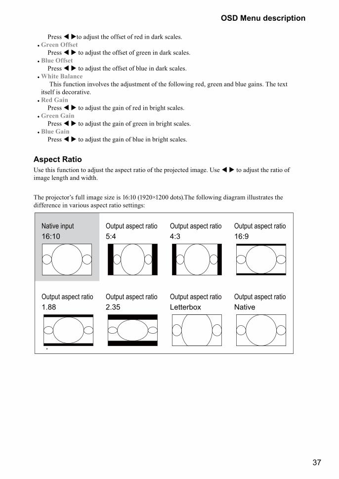
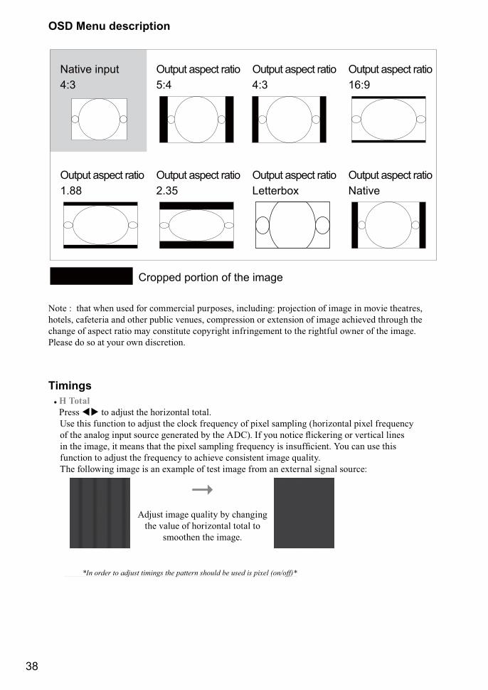
Aspect RatioUse this function to adjust the aspect ratio of the projected image. Use � � to adjust the ratio of image length and width.
J�� ��������+� ���� ���� ��@� �� ��X�� �����¢���� ���¡�J�� ��������� ����� �������� �� difference in various aspect ratio settings:
Native input 16:10
Output aspect ratio16:9
Output aspect ratio1.88
Output aspect ratio2.35
Output aspect ratio5:4
Output aspect ratio4:3
Output aspect ratioNative
Output aspect ratioLetterbox
38
OSD Menu description
Native input 4:3
Output aspect ratio16:9
Output aspect ratio1.88
Output aspect ratio2.35
Output aspect ratio5:4
Output aspect ratio4:3
Output aspect ratioNative
Output aspect ratioLetterbox
Cropped portion of the image
Note : that when used for commercial purposes, including: projection of image in movie theatres, hotels, cafeteria and other public venues, compression or extension of image achieved through the change of aspect ratio may constitute copyright infringement to the rightful owner of the image. Please do so at your own discretion.
Timings# H Total
Press �� to adjust the horizontal total. Use this function to adjust the clock frequency of pixel sampling (horizontal pixel frequency �� �� ���� ���� ������ ������� &" �� ]Q�¡� �� "�� ����� `�������� �� %����� ����� �� �� ����> � ���� � �� ��$�� ������� ���=����" �� ����������� ��� �� ��� ��� function to adjust the frequency to achieve consistent image quality. The following image is an example of test image from an external signal source:
��Adjust image quality by changing
the value of horizontal total to smoothen the image.
� F������������ �������� ������������� �������� ��� ���%���'�H��=F
39
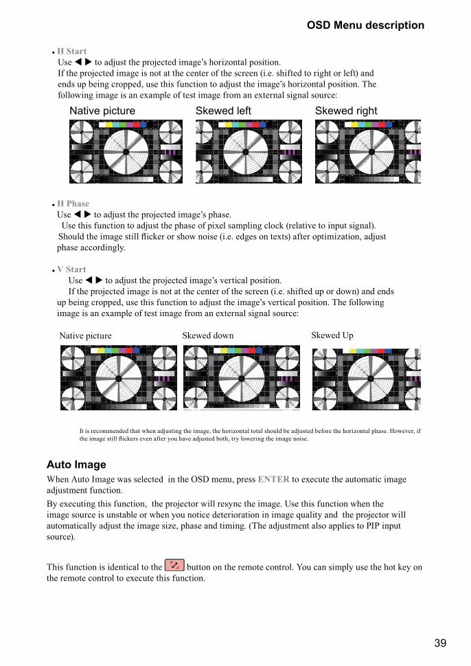
OSD Menu description
# H Start Use � � � ���� �� �������� ����+� ����@��� �������� If the projected image is not at the center of the screen (i.e. shifted to right or left) and ���� �� &���� �������> ��� ��� ������� � ���� �� ����+� ����@��� �������� J�� following image is an example of test image from an external signal source:
Native picture Skewed left Skewed right
# H Phase Use � � � ���� �� �������� ����+� ����� Use this function to adjust the phase of pixel sampling clock (relative to input signal). ������ �� ���� ���� `����� �� ���� ����� ����� ����� �� �$�¡ ��� �����@���> ���� phase accordingly.
# V Start Use � � � ���� �� �������� ����+� %����� �������� If the projected image is not at the center of the screen (i.e. shifted up or down) and ends �� &���� �������> ��� ��� ������� � ���� �� ����+� %����� �������� J�� ��������� image is an example of test image from an external signal source:
Native picture Skewed down Skewed Up
It is recommended that when adjusting the image, the horizontal total should be adjusted before the horizontal phase. However, if �� ���� ���� `������ �%�� ��� "�� �%� ������ &��> �" �������� �� ���� ������
Auto ImageWhen Auto Image was selected in the OSD menu, press ENTER to execute the automatic image adjustment function.By executing this function, the projector will resync the image. Use this function when the image source is unstable or when you notice deterioration in image quality and the projector will automatically adjust the image size, phase and timing. (The adjustment also applies to PIP input source).
This function is identical to the button on the remote control. You can simply use the hot key on the remote control to execute this function.
40
OSD Menu description
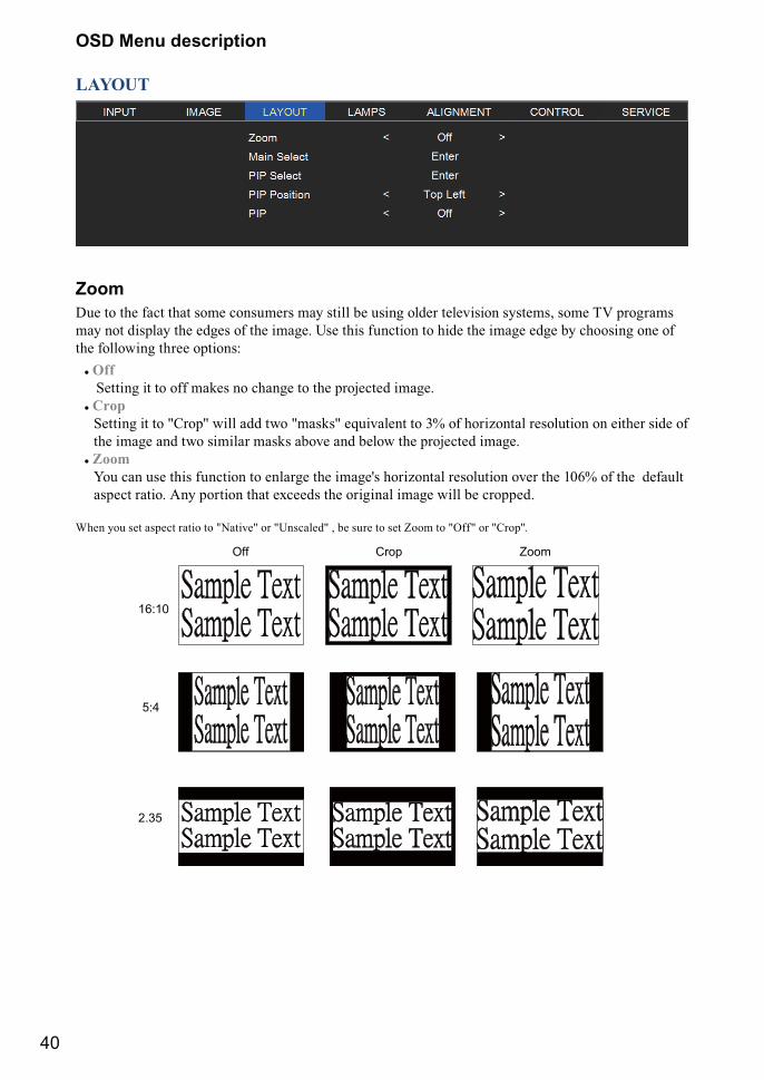
LAYOUT
ZoomDue to the fact that some consumers may still be using older television systems, some TV programs may not display the edges of the image. Use this function to hide the image edge by choosing one of the following three options:
# Off Setting it to off makes no change to the projected image.
# Crop Setting it to "Crop" will add two "masks" equivalent to 3% of horizontal resolution on either side of the image and two similar masks above and below the projected image.
# Zoom You can use this function to enlarge the image's horizontal resolution over the 106% of the default aspect ratio. Any portion that exceeds the original image will be cropped.
When you set aspect ratio to "Native" or "Unscaled" , be sure to set Zoom to "Off" or "Crop".
16:10
Off Crop Zoom
5:4
2.35
41
OSD Menu description
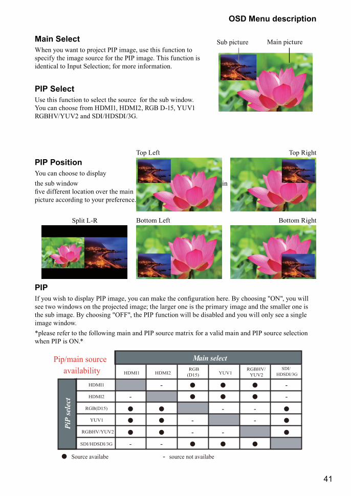
Main SelectWhen you want to project PIP image, use this function to specify the image source for the PIP image. This function is identical to Input Selection; for more information.
PIP SelectUse this function to select the source for the sub window. You can choose from HDMI1, HDMI2, RGB D-15, YUV1 RGBHV/YUV2 and SDI/HDSDI/3G.
PIP PositionYou can choose to display the sub window in �%� �������� ������ �%�� �� ��� picture according to your preference.
PIP�� "�� ���� � �����" ��� ����> "�� �� ��� �� ���������� ����� �" �������� }��}> "�� ���� see two windows on the projected image; the larger one is the primary image and the smaller one is the sub image. By choosing "OFF", the PIP function will be disabled and you will only see a single image window.*please refer to the following main and PIP source matrix for a valid main and PIP source selection when PIP is ON.*
Main select
Source availabe - source not availabe
PiP
sele
ct
HDMI1
HDMI2
RGB(D15)
YUV1
RGBHV/YUV2
SDI/HDSDI/3G
HDMI1
-
-
HDMI2
-
-
RGBHV/YUV2
--
SDI/HDSDI/3G
--
RGB(D15)
-- -
YUV1
-
Pip/main sourceavailability
Sub picture Main picture
Split L-R Bottom RightBottom Left
Top RightTop Left
42
OSD Menu description
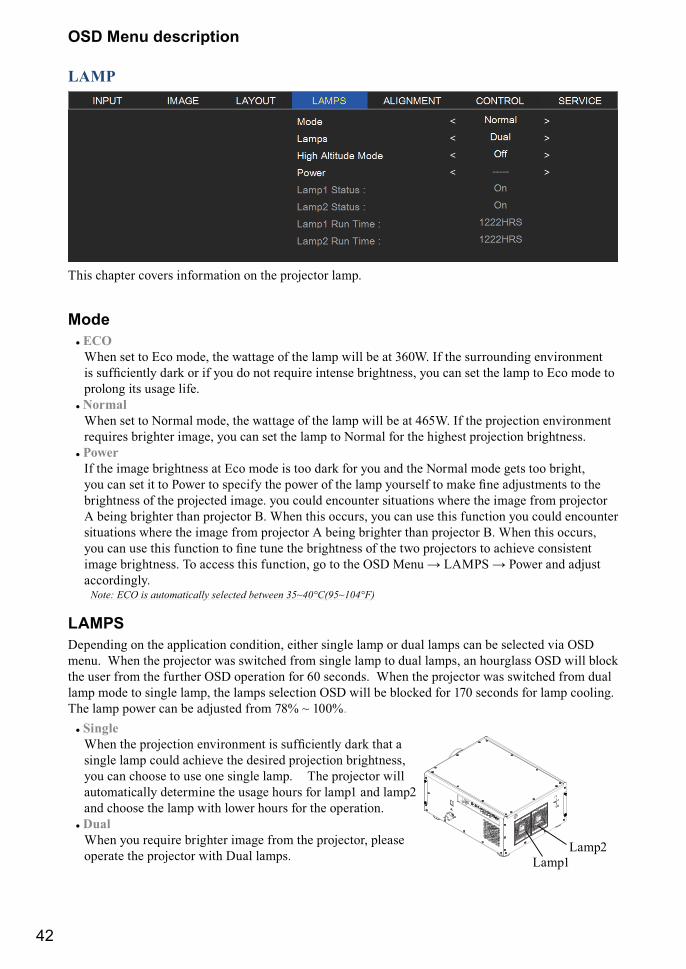
LAMP
This chapter covers information on the projector lamp.
Mode# ECO
When set to Eco mode, the wattage of the lamp will be at 360W. If the surrounding environment �� ���������" ��� �� �� "�� �� �� ��=���� ������ &��������> "�� �� �� �� ��� � ��� ���� � prolong its usage life.
# Normal When set to Normal mode, the wattage of the lamp will be at 465W. If the projection environment requires brighter image, you can set the lamp to Normal for the highest projection brightness.
# Power If the image brightness at Eco mode is too dark for you and the Normal mode gets too bright, "�� �� �� � � ����� � ������" �� ����� �� �� ��� "������� � ��� ��� �������� � �� brightness of the projected image. you could encounter situations where the image from projector A being brighter than projector B. When this occurs, you can use this function you could encounter situations where the image from projector A being brighter than projector B. When this occurs, "�� �� ��� ��� ������� � ��� ��� �� &�������� �� �� �� ��������� � ����%� �������� ���� &��������� J� ����� ��� �������> �� � �� ��Q <��� � �]<�� � ����� �� ���� accordingly.
Note: ECO is automatically selected between 35~40°C(95~104°F)
LAMPSDepending on the application condition, either single lamp or dual lamps can be selected via OSD menu. When the projector was switched from single lamp to dual lamps, an hourglass OSD will block the user from the further OSD operation for 60 seconds. When the projector was switched from dual lamp mode to single lamp, the lamps selection OSD will be blocked for 170 seconds for lamp cooling. The lamp power can be adjusted from 78% ~ 100%.
# Single {��� �� ��������� ��%������� �� ���������" ��� � single lamp could achieve the desired projection brightness, you can choose to use one single lamp. The projector will automatically determine the usage hours for lamp1 and lamp2 and choose the lamp with lower hours for the operation.
# Dual When you require brighter image from the projector, please operate the projector with Dual lamps. Lamp1
Lamp2
43
OSD Menu description
High Altitude ModeUse this function to control the projector's cooling fan. You can set it to Off or On. The default setting is Off. Under normal circumstances, the projector will operate normally with this function set to Off. By default, the projector will detect the temperature of the surrounding environment to regulate the speed of the cooling fan. When the ambient temperature rises, fan speed will increase (generates louder noise) to make sure the heat inside the projector gets discharged and keep the projector working normally.
However, if you were to operate the projector in environment of excessive heat or in areas of high altitude, the projector may automatically shut down. When this happens, you can enable this function by setting it to On to force the cooling fan to work at a higher speed to regulate the temperature inside the projector.
# High altitude region refers to area with elevation over 1500 meters (4900 feet).# When operating in normal altitude environments, the projector will adjust the cooling fan
according to the temperature of the working environment. When the temperature rises above 30C, the projector will automatically increase fan speed.
# ]�������� � �� ������ ����������> �� �$���� ������� ����� ��� �� �������� �� [email protected] means that you should not be operating the projector in high altitudes when the working environment is over 25C. (Due to the air thinning substantially at high altitudes, the result of cooling achieved by the cooling �� �� ���������" ������� ������� � ������� �� ��%�� ������� {�� ��� ��������� �������� and high operating temperature, the cooling fan will not be able to disperse the heat adequately)
PowerThis function will not be available if you have set the lamp to Eco or Normal modes, you can only adjust this setting when the lamp has been set to ”Power”. You can specify the lamp power in the range of 78% ~ 100%. Generally speaking, the lower the power, the dimmer the image will be but the lamp will have longer lifecycle. In contrast, the higher the power, the brighter the image will be at the cost of shorter lamp lifecycle.
Lamp1 StatusThis function is limited to display purposes to inform the user of Lamp1 status (On or Off).
Lamp2 StatusThis function is limited to display purposes to inform the user of Lamp2 status (On or Off).
Lamp1 Run TimeThis function is limited to display purposes to inform the user of Lamp1's total run time.
Lamp2 Run TimeThis function is limited to display purposes to inform the user of Lamp2's total run time.
44
OSD Menu description
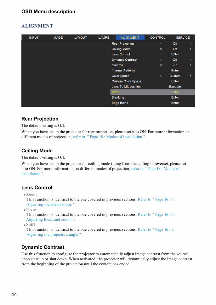
ALIGNMENT
Rear ProjectionThe default setting is Off.When you have set up the projector for rear projection, please set it to ON. For more information on different modes of projection, refer to " Page 18 : Modes of installation ".
Ceiling ModeThe default setting is Off.When you have set up the projector for ceiling mode (hung from the ceiling in reverse), please set it to ON. For more information on different modes of projection, refer to " Page 18 : Modes of installation ".
Lens Control# Zoom
This function is identical to the one covered in previous sections. Refer to " Page 16 : 6. Adjusting focus and zoom. ".
# Focus This function is identical to the one covered in previous sections. Refer to " Page 16 : 6. Adjusting focus and zoom. ".
# Shift This function is identical to the one covered in previous sections. Refer to " Page 16 : 5. Adjusting the projector's angle ".
Dynamic Contrast[�� ��� ������� � �������� �� �������� � �������" ���� ���� ����� ���� �� ������ upon start up or shut down. When activated, the projector will dynamically adjust the image contrast from the beginning of the projection until the content has ended.
45
OSD Menu description
GammaDifferent Gamma settings will affect viewers' perception of the image. Generally speaking, for images that are darker, it is recommended that Gamma be set higher to yield better image quality in darker ������� &" ��������� ����� �� &������ ���� �� �����> ���� ��������� &������ �����> "�� �� set the Gamma lower to give up details in the darker areas to make the brighter areas (i.e. clouds) more visible.
��� �� ������ ���� �%� �������� ��� ������ ����> ���> ���> ���?> ��? �� Q���� ���¡ �� �� projector. The projector's default gamma value is at 2.2.
�%��" ����� �� ��������" ������ ����� � �����" �� �����" ������ ����> �����> &���¡ �� secondary colors (yellow, cyan, magenta) in millions of pixels. Changing any number in the setting will change the resulting color and rearrange the color "triangle".
Internal PatternsThe projector comes with some standard built-in patterns for testers to calibrate the equipment. These include:0 = Off 1 = Color Bars 2 = Hatch 3 = Burst 4 = Red5 = Green 6 = Blue 7 = White 8 = Black 9 = TI-Red10 = TI-Green 11 = TI-Blue 12 = TI-Ramp
Color SpaceUsing different color space will create different color presentation in the projected image. You can choose from the following color gamma:Native Choose this to apply the projector's native color gamutEBU Choose this to apply the EBU color gamut; it is primarily suited for input devices using PAL,
576i, 576p and so forth.SMPTE Choose this to apply the SMPTE color gamut; it is primarily suited for input devices using
NTSC, 480i, 480p and so forth.Custom Choose this to customize the color gamut according to your preference through projector
Toolset application.
Lens To MidpositionAfter series of lens shift operations, this function can be used to return the lens to the center position.
46
OSD Menu description
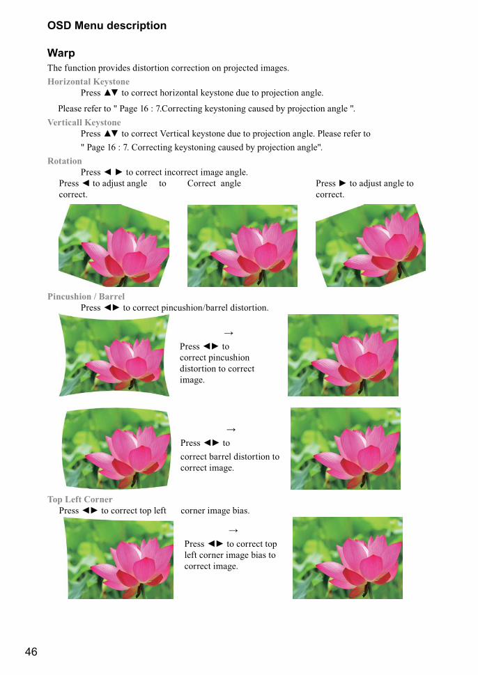
WarpThe function provides distortion correction on projected images.Horizontal Keystone ����� �� � ������ ����@��� ��"���� ��� � ��������� �����
Please refer to " Page 16 : 7.Correcting keystoning caused by projection angle ".Verticall Keystone ����� �� � ������ ������ ��"���� ��� � ��������� ����� ����� ����� � " Page 16 : 7. Correcting keystoning caused by projection angle".Rotation ����� ¤ ¥ � ������ �������� ���� �����
Correct angle Press + to adjust angle to correct.
����� ¤ � ���� ���� � correct.
Pincushion / Barrel ����� ¤¥ � ������ �����������&���� ���������
������ ¤¥ � correct pincushion distortion to correct image.
������ ¤¥ � correct barrel distortion to correct image.
Top Left Corner ����� ¤¥ � ������ �� ��� ������ ���� &���
������ ¤¥ � ������ �� left corner image bias to correct image.
47
OSD Menu description
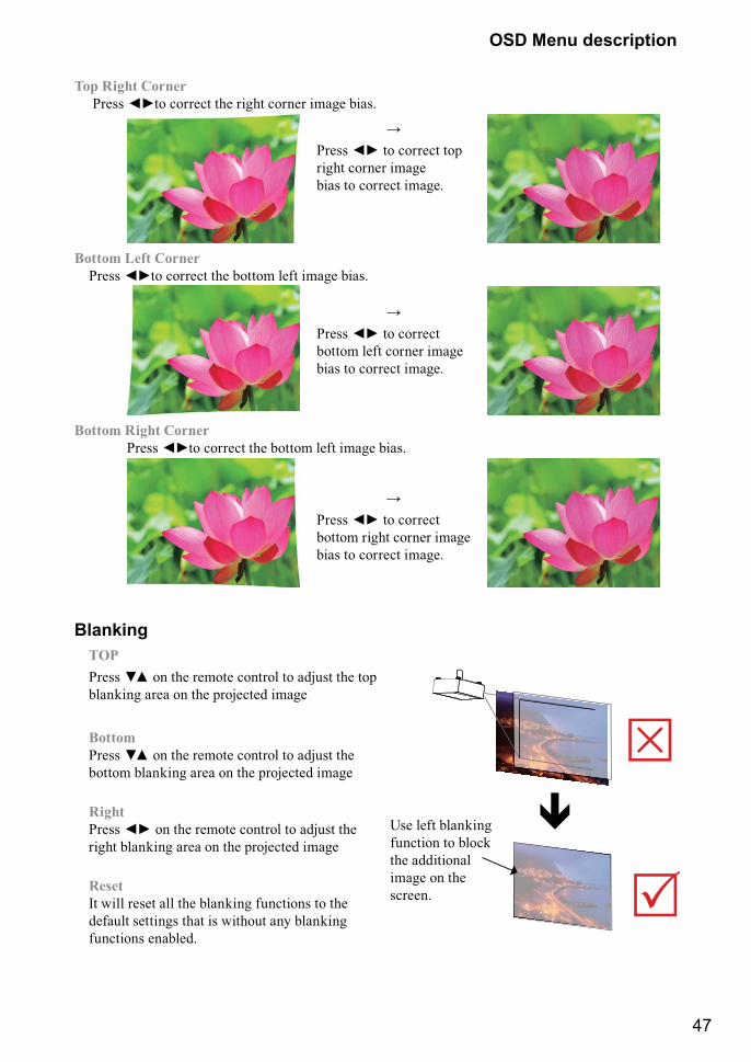
Top Right Corner ����� ¤¥� ������ �� ���� ������ ���� &���
������ ¤¥ � ������ �� right corner image bias to correct image.
Bottom Left Corner ����� ¤¥� ������ �� &��� ��� ���� &���
������ ¤¥ � ������ bottom left corner image bias to correct image.
Bottom Right Corner ����� ¤¥� ������ �� &��� ��� ���� &���
������ ¤¥ � ������ bottom right corner image bias to correct image.
Blanking
�
�
Use left blanking function to block the additional image on the screen.
TOP����� �� �� �� ����� ������ � ���� �� �� blanking area on the projected image
Bottom ����� �� �� �� ����� ������ � ���� �� bottom blanking area on the projected image
Right ����� ¤¥ �� �� ����� ������ � ���� �� right blanking area on the projected image
Reset It will reset all the blanking functions to the default settings that is without any blanking functions enabled.
48
OSD Menu description
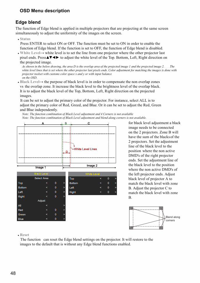
Edge blend The function of Edge blend is applied in multiple projectors that are projecting at the same screen simultaneously to adjust the uniformity of the images on the screen.
# Status Press ENTER to select ON or OFF. The function must be set to ON in order to enable the function of Edge blend. If the function is set to OFF, the function of Edge blend is disabled.
# White Level� ���� ��%�� �� � �� �� ���� ���� ��� �������� ����� �� ���� �������� �� ��$�� ����� �������¤¥ � ���� �� ���� ��%�� �� �� J��� ����> ���> ���� �������� �� the projected image.
K � �>������������>���>��������������L�� �������������������������������������*����������������������/�� �Q���>��������������� ������� � ���>������������������������ ����%�� ��� ��X������ ��������������������������� �� ����>�������������� ���>������ �� ����� �����%��������>������������������ on the OSD.
# Black Level� �� ������� �� &��� ��%�� �� �� ����� � �������� �� ��� �%���� @���� vs the overlap zone. It increase the black level to the brightness level of the overlap black. It is to adjust the black level of the Top, Bottom, Left, Right direction on the projected images. It can be set to adjust the primary color of the projector. For instance, select ALL is to adjust the primary color of Red, Greed, and Blue. Or it can be set to adjust the Red, Green and Blue independently.
"��$�Q�����������������������������Y�������� ���������Z�X���� �� ������������� "��$�Q�����������������������������Y�������� ������������������������ �� ���������������
Image 1 Image 2
A B C
DWhite Level Lines
Image 1 Image 2
A B C
DWhite Level Lines
for black level adjustment a black image needs to be connected on the 2 projectors. Zone B will have the sum of the blacks of the 2 projectors. Set the adjustment line of the black level to the position where the non active DMD's of the right projector ends. Set the adjustment line of the black level to the position where the non active DMD's of the left projector ends. Adjust black level of projector A to match the black level with zone B. Adjust the projector C to match the black level with zone B.
Blend along corners
# Reset The function can reset the Edge blend settings on the projector. It will restore to the images to the default that is without any Edge blend functions enabled.
49
OSD Menu description
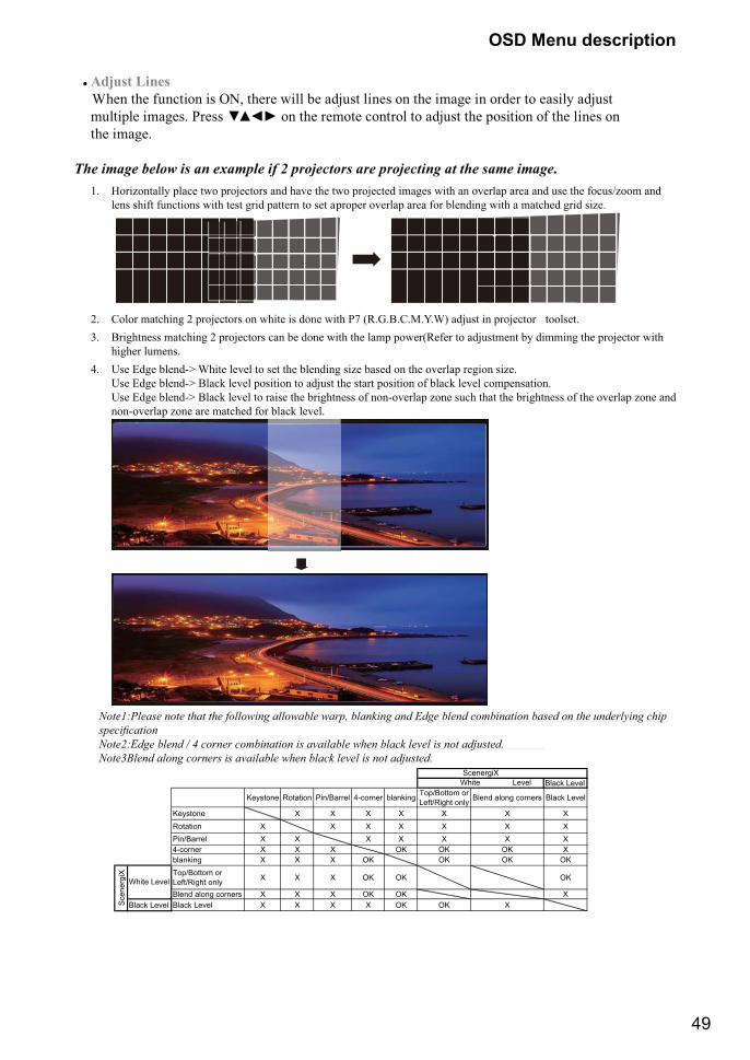
# Adjust Lines When the function is ON, there will be adjust lines on the image in order to easily adjust ������� ������ ����� ��¤¥ �� �� ����� ������ � ���� �� ������� �� �� ����� �� the image.
The image below is an example if 2 projectors are projecting at the same image.
1. Horizontally place two projectors and have the two projected images with an overlap area and use the focus/zoom and lens shift functions with test grid pattern to set a proper overlap area for blending with a matched grid size.
�2. Color matching 2 projectors on white is done with P7 (R.G.B.C.M.Y.W) adjust in projector toolset.3. Brightness matching 2 projectors can be done with the lamp power(Refer to adjustment by dimming the projector with
higher lumens.4. Use Edge blend-> White level to set the blending size based on the overlap region size.
Use Edge blend-> Black level position to adjust the start position of black level compensation. Use Edge blend-> Black level to raise the brightness of non-overlap zone such that the brightness of the overlap zone and non-overlap zone are matched for black level.
�
Note1:Please note that the following allowable warp, blanking and Edge blend combination based on the underlying chip ����������� "��/$[��������H�Z������������������ �����������>����������������� ������� ���� "��8��������������� �� �����������>����������������� ������� ���
Black Level Black Level
Black Level
Keystone Rotation Pin/Barrel 4-corner blanking Top/Bottom orLeft/Right only Blend along corners Black Level
Keystone X X X X X X XRotation X X X X X X XPin/Barrel X X X X X X X4-corner X X X OK OK OK Xblanking X X X OK OK OK OKTop/Bottom orLeft/Right only X X X OK OK OK
Blend along corners X X X OK OK XX X X X OK OK X
ScenergiX
Sce
nerg
iX
White Level
White Level
50
OSD Menu description
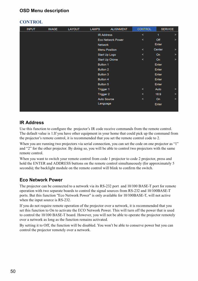
CONTROL
IR Address[�� ��� ������� � �������� �� ��������+� �� ���� �����%� ������� ���� �� ����� ������� The default value is 1.If you have other equipment in your home that could pick up the command from �� ��������+� ����� ������> � �� ����������� � "�� �� �� ����� ������ ���� � ��When you are running two projectors via serial connection, you can set the code on one projector as “1” and “2” for the other projector. By doing so, you will be able to control two projectors with the same remote control.When you want to switch your remote control from code 1 projector to code 2 projector, press and hold the ENTER and ADDRESS buttons on the remote control simultaneously (for approximately 5 �������¡� �� &������ ������ �� �� ����� ������ ���� &���� � ������ �� ������
Eco Network PowerThe projector can be connected to a network via its RS-232 port and 10/100 BASE-T port for remote operation with two separate boards to control the signal sources from RS-232 and 10/100BASE-T ports. But this function "Eco Network Power" is only available for 10/100BASE-T, will not active when the input source is RS-232. If you do not require remote operation of the projector over a network, it is recommended that you set this function to On to activate the ECO Network Power. This will turn off the power that is used to control the 10/100 BASE-T board. However, you will not be able to operate the projector remotely over a network as long as the function remains activated.�" ����� � � ���> �� ������� ���� &� ���&���� ��� ���+ &� &�� � ������%� ����� &� "�� �� control the projector remotely over a network.
51
OSD Menu description
NetworkTo control the projector via network, after connecting the network cables for a PC and the projector, you can use this OSD function to view the relevant network information (such as IP Address, Subnet <��> ���" �� Q_��¡ �� �� ��������� ����� �������� �� �� � &� �������� � �� �������� with a proper IP address with the same subnet mask, gateway as the projector. The default IP address of the projector is 192.168.0.100. The network settings of the projector can only be changed through the web-page control or projector Toolset application.To control the projector via network, please connect to the projector via a web browser with the IP address shown on the OSD menu CONTROL -> Network.
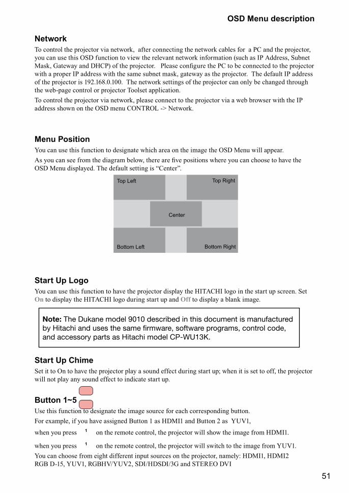
Menu PositionYou can use this function to designate which area on the image the OSD Menu will appear.]� "�� �� ��� ���� �� ����� &����> ���� �� �%� �������� ����� "�� �� ������ � �%� �� OSD Menu displayed. The default setting is “Center”.
Top Left
Center
Bottom Left
Top Right
Bottom Right
Start Up LogoYou can use this function to have the projector display the HITACHI logo in the start up screen. Set On to display the HITACHI logo during start up and Off to display a blank image.
Start Up ChimeSet it to On to have the projector play a sound effect during start up; when it is set to off, the projector will not play any sound effect to indicate start up.
Button 1~5Use this function to designate the image source for each corresponding button. For example, if you have assigned Button 1 as HDMI1 and Button 2 as YUV1,
when you press 1 on the remote control, the projector will show the image from HDMI1.
when you press 1 on the remote control, the projector will switch to the image from YUV1.You can choose from eight different input sources on the projector, namely: HDMI1, HDMI2 RGB D-15, YUV1, RGBHV/YUV2, SDI/HDSDI/3G and STEREO DVI
Note: The Dukane model 9010 described in this document is manufactured by Hitachi and uses the same firmware, software programs, control code, and accessory parts as Hitachi model CP-WU13K.
52
OSD Menu description
Trigger1 ~2J�� �������� ����� ��� �� ��� �� J������ ����� ��� �� �������� �� �������� ��%���� connected to the projector via the trigger ports to be automatically turned on when the projector is on. There will be a 2-3 second delay prior to activation to prevent operation of this function when the user is choosing the desired aspect ratio.5:4 Outputs 12V of power on Trigger1 or 2 when the user chooses the 5:4 aspect ratio.4:3 Outputs 12V of power on Trigger1 or 2 when the user chooses the 4:3 aspect ratio.16:10 Outputs 12V of power on Trigger1 or 2 when the user chooses the 16:10 aspect ratio.16:9 Outputs 12V of power on Trigger1 or 2 when the user chooses the 16:9 aspect ratio.1.88 Outputs 12V of power on Trigger1 or 2 when the user chooses the 1.88 aspect ratio.2.35 Outputs 12V of power on Trigger1 or 2 when the user chooses the 2.35 aspect ratio.Letterbox Outputs 12V of power on Trigger1 or 2 when the user chooses the Letterbox aspect
ratio.Native Outputs 12V of power on Trigger1 or 2 when the user chooses the native aspect ratio.Auto Outputs 12V of power on Trigger 1 or 2 when the projector is turned on.
Auto SourceSelect this function to active the projector automatically search input Imaging.ON: default setting. By enabling this function, the projector will automatically determine the source
of input every time it is turned on so that the user will not have to make the selection on the OSD Menu.
Setting the function off will require the user to specify source of image input on the OSD Menu in order for the projector to display the intended image.
This function is not available when the input source is Stereo-DVI.
LanguageYou can use this function to select the language you wish for the OSD Menu to be displayed in. You can choose from the following nine languages:�������> ������> ������> �����> ���������> ��������� �������> J������� �������> ¦����� and Korean.
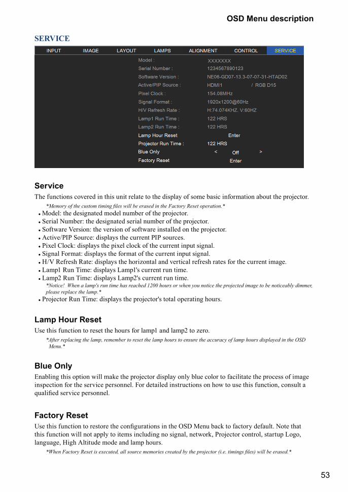
53
OSD Menu description
SERVICE
XXXXXXX
ServiceThe functions covered in this unit relate to the display of some basic information about the projector.
F]������������� ������������� �>���������� ���������^�������� �����������F# Model: the designated model number of the projector.# Serial Number: the designated serial number of the projector.# Software Version: the version of software installed on the projector.# Active/PIP Source: displays the current PIP sources.# Pixel Clock: displays the pixel clock of the current input signal.# Signal Format: displays the format of the current input signal.# H/V Refresh Rate: displays the horizontal and vertical refresh rates for the current image.# Lamp1 Run Time: displays Lamp1's current run time. # Lamp2 Run Time: displays Lamp2's current run time.
�F"����_��!����������` ������������ ��������*/<<���� ���>�����������������������������������������������������please replace the lamp.*
# Projector Run Time: displays the projector's total operating hours.
Lamp Hour ResetUse this function to reset the hours for lamp1 and lamp2 to zero.
* After replacing the lamp, remember to reset the lamp hours to ensure the accuracy of lamp hours displayed in the OSD Menu.*
Blue OnlyEnabling this option will make the projector display only blue color to facilitate the process of image inspection for the service personnel. For detailed instructions on how to use this function, consult a =������ ���%��� ����������
Factory Reset[�� ��� ������� � ������ �� ����������� �� �� ��Q <��� &�� � ����" ������ ��� � this function will not apply to items including no signal, network, Projector control, startup Logo, language, High Altitude mode and lamp hours.
F!����^�������� ���� ��%����������� ����������� �����������������������'����������� ���� =�>���������� ��F
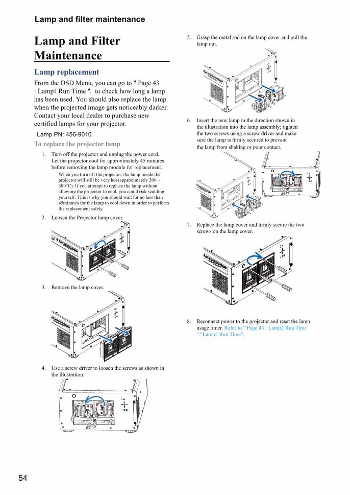
54
��� �� ���� ��������
Lamp and Filter MaintenanceLamp replacementFrom the OSD Menu, you can go to " Page 43 : Lamp1 Run Time ". to check how long a lamp has been used. You should also replace the lamp when the projected image gets noticeably darker. Contact your local dealer to purchase new ������� ���� ��� "��� ���������
To replace the projector lamp1. Turn off the projector and unplug the power cord.
Let the projector cool for approximately 45 minutes before removing the lamp module for replacement.
When you turn off the projector, the lamp inside the projector will still be very hot (approximately 200 ~ 300°C). If you attempt to replace the lamp without allowing the projector to cool, you could risk scalding yourself. This is why you should wait for no less than 45minutes for the lamp to cool down in order to perform the replacement safely.
2. Loosen the Projector lamp cover.
3. Remove the lamp cover.
4. Use a screw driver to loosen the screws as shown in the illustration.
5. Grasp the metal rod on the lamp cover and pull the lamp out.
6. Insert the new lamp in the direction shown in
the illustration into the lamp assembly; tighten the two screws using a screw driver and make ���� �� ��� �� ����" ������� � ���%�� the lamp from shaking or poor contact.
7. ������ �� ��� ��%�� �� ����" ������ �� �� screws on the lamp cover.
8. Reconnect power to the projector and reset the lamp usage timer. Refer to " Page 43 : Lamp2 Run Time "."Lamp2 Run Time".
Lamp PN: 456-9010
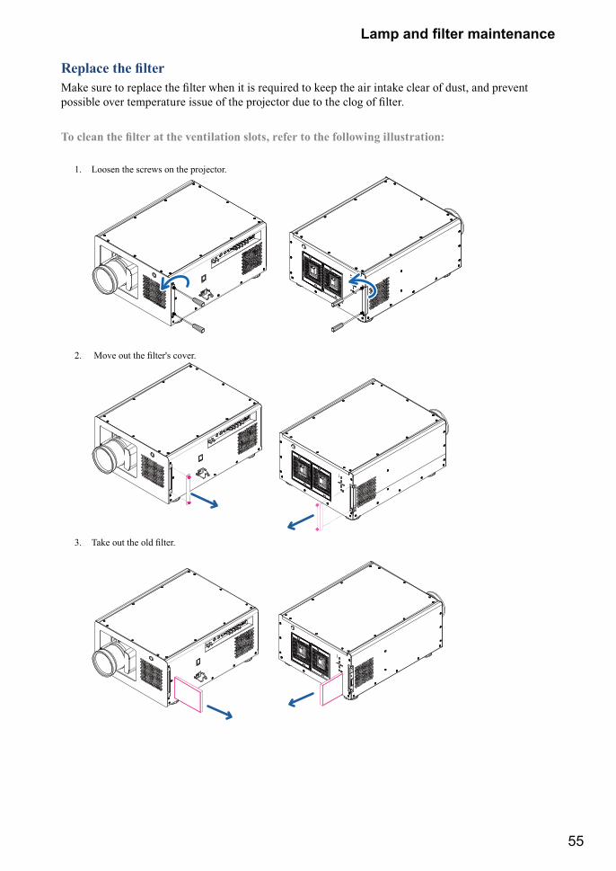
55
��� �� ���� ��������
������������� <�� ���� � ������ �� ���� ���� � �� ��=����� � ���� �� �� ���� ���� �� ���> �� ���%�� �����&�� �%�� �������� ����� �� �� �������� ��� � �� ���� �� �����
;������������� ������<�������������=� �!� ������!�������������� ����>�
1. Loosen the screws on the projector.
2. <�%� �� �� ����§� ��%���
3. J�� �� �� ��� �����
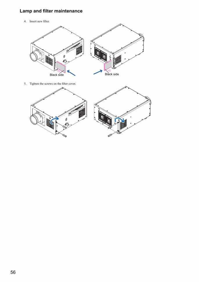
56
��� �� ���� ��������
4. ����� ��� �����
Black side Black side
5. J����� �� ������ �� �� ���� ��%���
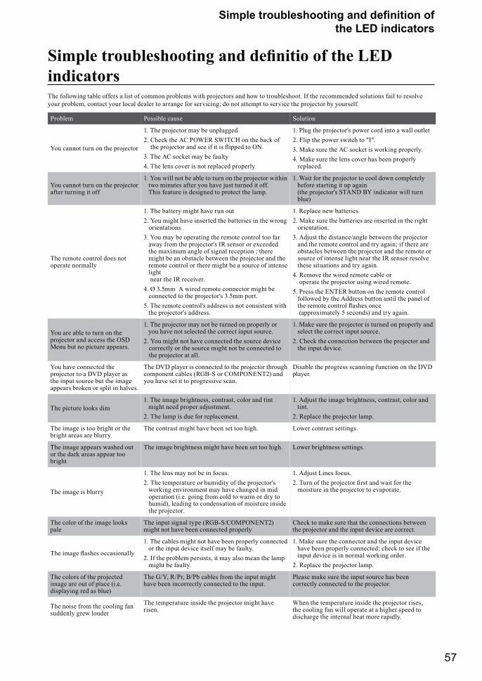
57
������ ������������� �� �������� �� the LED indicators
������� ��������������������������!����?@J�indicatorsThe following table offers a list of common problems with projectors and how to troubleshoot. If the recommended solutions fail to resolve your problem, contact your local dealer to arrange for servicing; do not attempt to service the projector by yourself.
Problem Possible cause Solution
You cannot turn on the projector
1. The projector may be unplugged2. Check the AC POWER SWITCH on the back of
�� �������� �� ��� �� � �� `����� � ���3. The AC socket may be faulty4. The lens cover is not replaced properly
1. Plug the projector's power cord into a wall outlet2. Flip the power switch to "I".3. Make sure the AC socket is working properly.4. Make sure the lens cover has been properly
replaced.
You cannot turn on the projector after turning it off
1. You will not be able to turn on the projector within two minutes after you have just turned it off. This feature is designed to protect the lamp.
1. Wait for the projector to cool down completely before starting it up again (the projector's STAND BY indicator will turn blue)
The remote control does not operate normally
1. The battery might have run out2. You might have inserted the batteries in the wrong
orientations3. You may be operating the remote control too far
away from the projector's IR sensor or exceeded the maximum angle of signal reception ; there might be an obstacle between the projector and the remote control or there might be a source of intense light near the IR receiver.
4. Ø 3.5mm A wired remote connector might be connected to the projector's 3.5mm port.
5. The remote control's address is not consistent with the projector's address.
1. Replace new batteries2. Make sure the batteries are inserted in the right
orientation.3. Adjust the distance/angle between the projector
and the remote control and try again; if there are obstacles between the projector and the remote or source of intense light near the IR sensor resolve these situations and try again.
4. Remove the wired remote cable or operate the projector using wired remote.
5. Press the ENTER button on the remote control followed by the Address button until the panel of �� ����� ������ `���� ���� (approximately 5 seconds) and try again.
You are able to turn on the projector and access the OSD Menu but no picture appears.
1. The projector may not be turned on properly or you have not selected the correct input source.
2. You might not have connected the source device correctly or the source might not be connected to the projector at all.
1. Make sure the projector is turned on properly and select the correct input source.
2. Check the connection between the projector and the input device.
You have connected the projector to a DVD player as the input source but the image appears broken or split in halves.
The DVD player is connected to the projector through component cables (RGB-S or COMPONENT2) and you have set it to progressive scan.
Disable the progress scanning function on the DVD player.
The picture looks dim1. The image brightness, contrast, color and tint
might need proper adjustment.2. The lamp is due for replacement.
1. Adjust the image brightness, contrast, color and tint.
2. Replace the projector lamp.
The image is too bright or the bright areas are blurry
The contrast might have been set too high. Lower contrast settings.
The image appears washed out or the dark areas appear too bright
The image brightness might have been set too high. Lower brightness settings.
The image is blurry
1. The lens may not be in focus.2. The temperature or humidity of the projector's
working environment may have changed in mid operation (i.e. going from cold to warm or dry to humid), leading to condensation of moisture inside the projector.
1. Adjust Lines focus.�� J��� �� �� �������� ��� �� �� ��� ��
moisture in the projector to evaporate.
The color of the image looks pale
The input signal type (RGB-S/COMPONENT2) might not have been connected properly
Check to make sure that the connections between the projector and the input device are correct.
J�� ���� `���� ���������"
1. The cables might not have been properly connected or the input device itself may be faulty.
2. If the problem persists, it may also mean the lamp might be faulty.
1. Make sure the connector and the input device have been properly connected; check to see if the input device is in normal working order.
2. Replace the projector lamp.
The colors of the projected image are out of place (i.e. displaying red as blue)
The G/Y, R/Pr, B/Pb cables from the input might have been incorrectly connected to the input.
Please make sure the input source has been correctly connected to the projector.
The noise from the cooling fan suddenly grew louder
The temperature inside the projector might have risen.
When the temperature inside the projector rises, the cooling fan will operate at a higher speed to discharge the internal heat more rapidly.
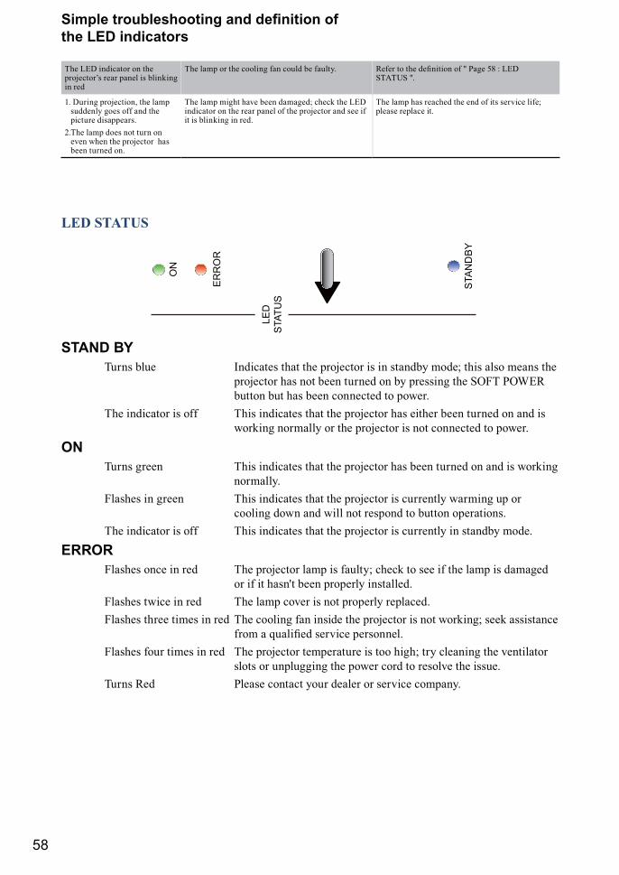
58
������ ������������� �� �������� �� the LED indicators
The LED indicator on the ��������+� ��� ���� �� &������� in red
The lamp or the cooling fan could be faulty. ����� � �� �������� �� } ��� ?� X ��Q STATUS ".
1. During projection, the lamp suddenly goes off and the picture disappears.
2. The lamp does not turn on even when the projector has been turned on.
The lamp might have been damaged; check the LED indicator on the rear panel of the projector and see if it is blinking in red.
The lamp has reached the end of its service life; please replace it.
LED STATUS
STAND BY Turns blue Indicates that the projector is in standby mode; this also means the
projector has not been turned on by pressing the SOFT POWER button but has been connected to power.
The indicator is off This indicates that the projector has either been turned on and is working normally or the projector is not connected to power.
ON Turns green This indicates that the projector has been turned on and is working
normally. Flashes in green This indicates that the projector is currently warming up or
cooling down and will not respond to button operations. The indicator is off This indicates that the projector is currently in standby mode.
ERROR Flashes once in red The projector lamp is faulty; check to see if the lamp is damaged or if it hasn't been properly installed. Flashes twice in red The lamp cover is not properly replaced. Flashes three times in red The cooling fan inside the projector is not working; seek assistance
���� =������ ���%��� ���������� Flashes four times in red The projector temperature is too high; try cleaning the ventilator
slots or unplugging the power cord to resolve the issue. Turns Red Please contact your dealer or service company.
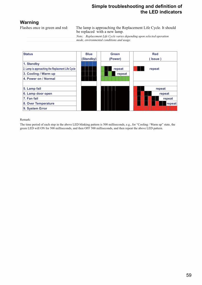
59
������ ������������� �� �������� �� the LED indicators
WarningFlashes once in green and red: The lamp is approaching the Replacement Life Cycle. It should be replaced with a new lamp.
Note; Replacement Life Cycle varies depending upon selected operation mode, environmental conditions and usage.
Status Blue (Standby)
Green (Power)
Red ( Issue )
1. Standby 2. Lamp is approaching the Replacment Life Cycle repeat repeat 3. Cooling / Warm up repeat 4. Power on / Normal
5. Lamp fail repeat 6. Lamp door open repeat 7. Fan fail repeat 8. Over Temperature repeat 9. System Error
Remark:The time period of each step in the above LED blinking pattern is 500 milliseconds, e.g., for “Cooling / Warm up” state, the green LED will ON for 500 milliseconds, and then OFF 500 milliseconds, and then repeat the above LED pattern.
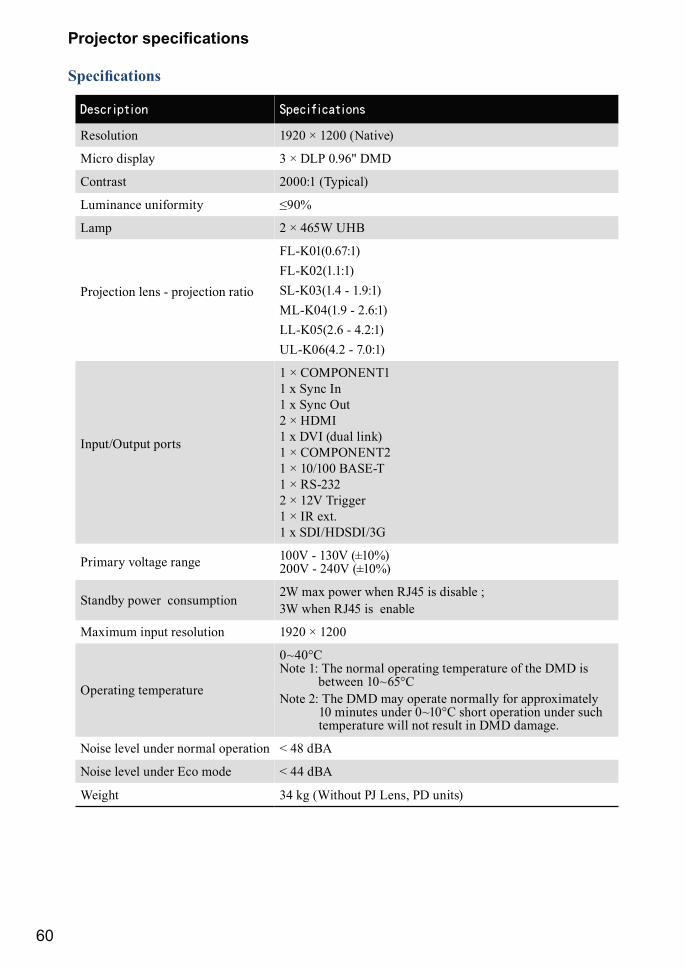
60
�������� �����������
����������
Resolution 1920 × 1200 (Native)
Micro display 3 × DLP 0.96" DMD
Contrast 2000:1 (Typical)
Luminance uniformity ¨��©
Lamp 2 × 465W UHB
Projection lens - projection ratio
FL-K01(0.67:1)FL-K02(1.1:1)SL-K03(1.4 - 1.9:1)ML-K04(1.9 - 2.6:1)LL-K05(2.6 - 4.2:1)UL-K06(4.2 - 7.0:1)
Input/Output ports
1 × COMPONENT1 1 x Sync In 1 x Sync Out 2 × HDMI 1 x DVI (dual link) 1 × COMPONENT2 1 × 10/100 BASE-T 1 × RS-232 2 × 12V Trigger 1 × IR ext. 1 x SDI/HDSDI/3G
Primary voltage range 100V - 130V (±10%) 200V - 240V (±10%)
Standby power consumption 2W max power when RJ45 is disable ; 3W when RJ45 is enable
Maximum input resolution 1920 × 1200
Operating temperature
0~40°C Note 1: The normal operating temperature of the DMD is
between 10~65°CNote 2: The DMD may operate normally for approximately
10 minutes under 0~10°C short operation under such temperature will not result in DMD damage.
Noise level under normal operation < 48 dBA
Noise level under Eco mode < 44 dBA
Weight 34 kg (Without PJ Lens, PD units)
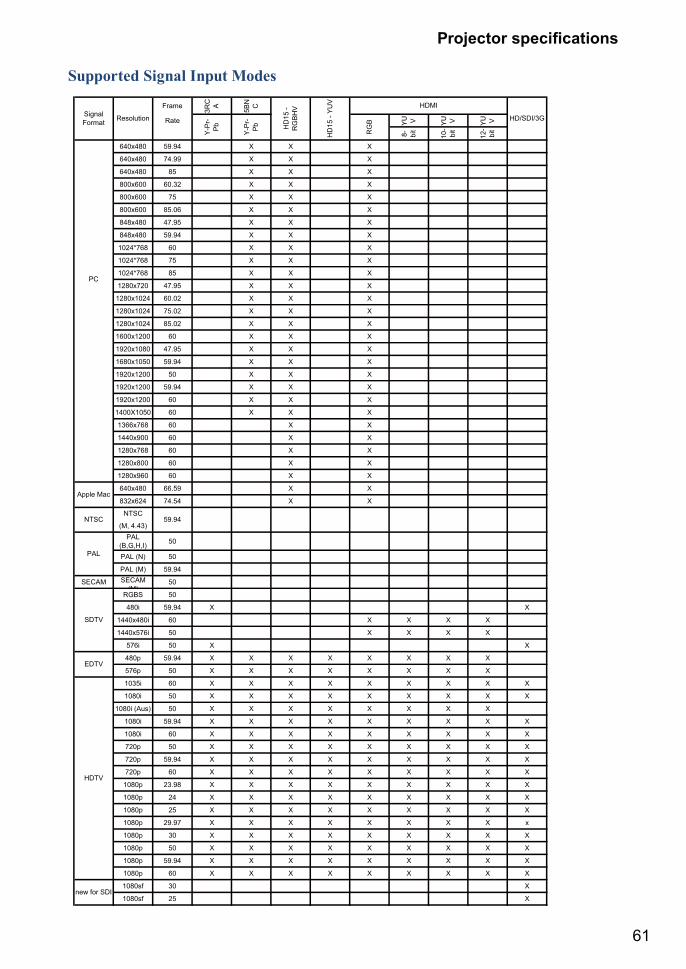
61
�������� �����������
Supported Signal Input Modes
Frame
3RC A 5BN C
Rate YU V YU V YU V
8- bit
10-
bit
12-
bit
640x480 59.94 X X X
640x480 74.99 X X X
640x480 85 X X X
800x600 60.32 X X X
800x600 75 X X X
800x600 85.06 X X X
848x480 47.95 X X X
848x480 59.94 X X X
1024*768 60 X X X
1024*768 75 X X X
1024*768 85 X X X
1280x720 47.95 X X X
1280x1024 60.02 X X X
1280x1024 75.02 X X X
1280x1024 85.02 X X X
1600x1200 60 X X X
1920x1080 47.95 X X X
1680x1050 59.94 X X X
1920x1200 50 X X X
1920x1200 59.94 X X X
1920x1200 60 X X X
1400X1050 60 X X X
1366x768 60 X X
1440x900 60 X X
1280x768 60 X X
1280x800 60 X X
1280x960 60 X X
640x480 66.59 X X
832x624 74.54 X X
NTSC
(M, 4.43)PAL
(B,G,H,I) 50
PAL (N) 50
PAL (M) 59.94
SECAM SECAM(M)
50
RGBS 50
480i 59.94 X X
1440x480i 60 X X X X
1440x576i 50 X X X X
576i 50 X X
480p 59.94 X X X X X X X X
576p 50 X X X X X X X X
1035i 60 X X X X X X X X X
1080i 50 X X X X X X X X X
1080i (Aus) 50 X X X X X X X X
1080i 59.94 X X X X X X X X X
1080i 60 X X X X X X X X X
720p 50 X X X X X X X X X
720p 59.94 X X X X X X X X X
720p 60 X X X X X X X X X
1080p 23.98 X X X X X X X X X
1080p 24 X X X X X X X X X
1080p 25 X X X X X X X X X
1080p 29.97 X X X X X X X X x
1080p 30 X X X X X X X X X
1080p 50 X X X X X X X X X
1080p 59.94 X X X X X X X X X
1080p 60 X X X X X X X X X
1080sf 30 X
1080sf 25 X
HDMI
HD/SDI/3G
Y-P
r-P
b
Y-P
r-P
b
RG
B
SignalFormat Resolution
HD
15 -
RG
BHV
HD
15 -
YU
V
PC
Apple Mac
NTSC 59.94
HDTV
new for SDI
PAL
SDTV
EDTV
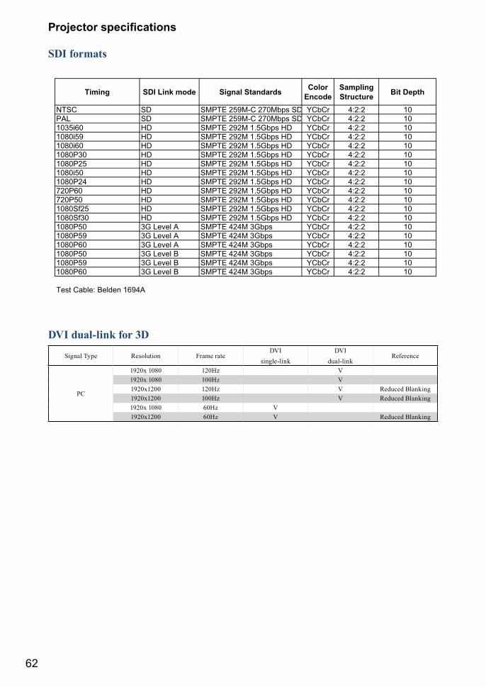
62
�������� �����������
SDI formats
Timing SDI Link mode Signal Standards ColorEncode
SamplingStructure Bit Depth
NTSC SD SMPTE 259M-C 270Mbps SD YCbCr 4:2:2 10PAL SD SMPTE 259M-C 270Mbps SD YCbCr 4:2:2 101035i60 HD SMPTE 292M 1.5Gbps HD YCbCr 4:2:2 101080i59 HD SMPTE 292M 1.5Gbps HD YCbCr 4:2:2 101080i60 HD SMPTE 292M 1.5Gbps HD YCbCr 4:2:2 101080P30 HD SMPTE 292M 1.5Gbps HD YCbCr 4:2:2 101080P25 HD SMPTE 292M 1.5Gbps HD YCbCr 4:2:2 101080i50 HD SMPTE 292M 1.5Gbps HD YCbCr 4:2:2 101080P24 HD SMPTE 292M 1.5Gbps HD YCbCr 4:2:2 10720P60 HD SMPTE 292M 1.5Gbps HD YCbCr 4:2:2 10720P50 HD SMPTE 292M 1.5Gbps HD YCbCr 4:2:2 101080Sf25 HD SMPTE 292M 1.5Gbps HD YCbCr 4:2:2 101080Sf30 HD SMPTE 292M 1.5Gbps HD YCbCr 4:2:2 101080P50 3G Level A SMPTE 424M 3Gbps YCbCr 4:2:2 101080P59 3G Level A SMPTE 424M 3Gbps YCbCr 4:2:2 101080P60 3G Level A SMPTE 424M 3Gbps YCbCr 4:2:2 101080P50 3G Level B SMPTE 424M 3Gbps YCbCr 4:2:2 101080P59 3G Level B SMPTE 424M 3Gbps YCbCr 4:2:2 101080P60 3G Level B SMPTE 424M 3Gbps YCbCr 4:2:2 10
Test Cable: Belden 1694A
DVI dual-link for 3D
Signal Type Resolution Frame rateDVI
single-linkDVI
dual-linkReference
PC
1920x 1080 120Hz V1920x 1080 100Hz V1920x1200 120Hz V Reduced Blanking1920x1200 100Hz V Reduced Blanking1920x 1080 60Hz V1920x1200 60Hz V Reduced Blanking
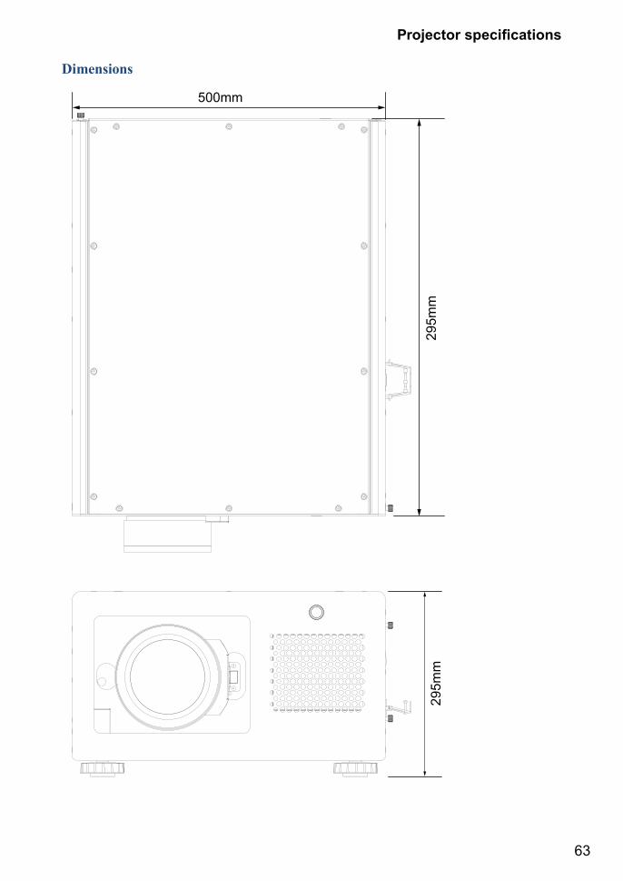
63
�������� �����������
Dimensions
295m
m29
5mm
500mm
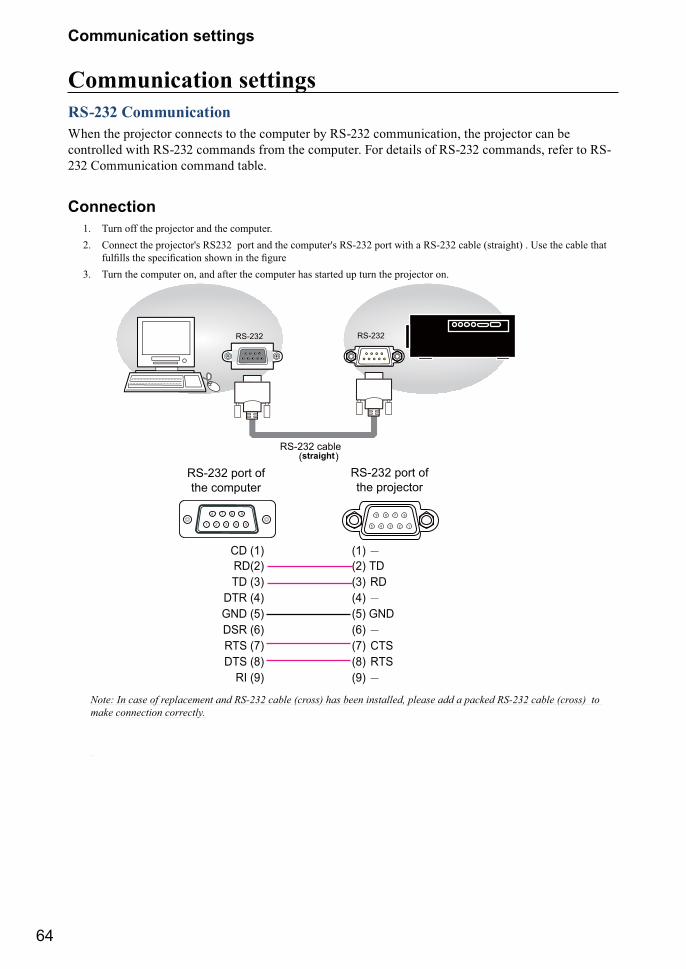
64
Communication settings
Communication settingsRS-232 CommunicationWhen the projector connects to the computer by RS-232 communication, the projector can be controlled with RS-232 commands from the computer. For details of RS-232 commands, refer to RS-232 Communication command table.
Connection1. Turn off the projector and the computer.2. Connect the projector's RS232 port and the computer's RS-232 port with a RS-232 cable (straight) . Use the cable that
������� �� ���������� ����� �� �� ����� 3. Turn the computer on, and after the computer has started up turn the projector on.
CD (1) (1) RD(2) (2) TDTD (3) (3) RD
DTR (4) (4) GND (5) (5) GNDDSR (6) (6) RTS (7) (7) CTSDTS (8) (8) RTS
RI (9) (9)
1 2 3 4 5 12345
789 69876
RS-232 port of the projector
RS-232 port of the computer
RS-232 cable(straight)
RS-232 RS-232
Note: In case of replacement and RS-232 cable (cross) has been installed, please add a packed RS-232 cable (cross) to make connection correctly.
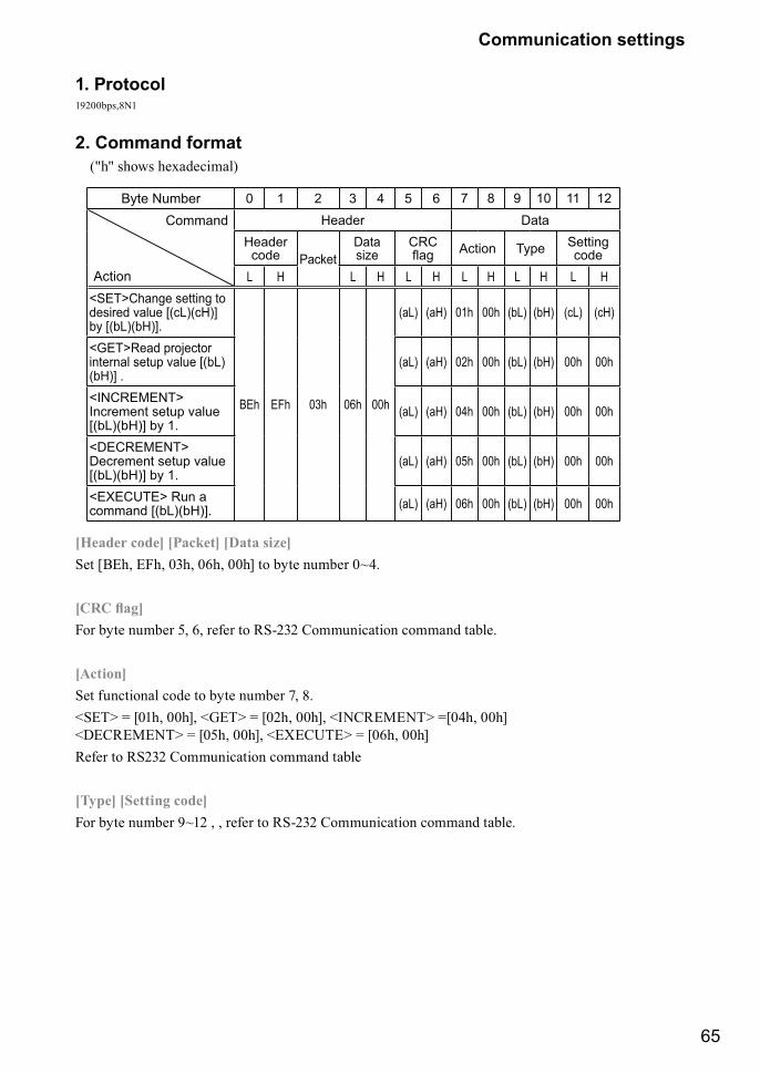
65
Communication settings
1. Protocol19200bps,8N1
2. Command format ("h" shows hexadecimal)
Byte Number 0 1 2 3 4 5 6 7 8 9 10 11 12
Command
Action
Header DataHeadercode Packet
Datasize
CRC ��� Action Type ������
codeL H L H L H L H L H L H
<SET>����� �������desired value [(cL)(cH)] by [(bL)(bH)].
BEh EFh 03h 06h 00h
(aL) (aH) 01h 00h (bL) (bH) (cL) (cH)
<GET>Read projector internal setup value [(bL)(bH)] .
(aL) (aH) 02h 00h (bL) (bH) 00h 00h
<INCREMENT> Increment setup value [(bL)(bH)] by 1.
(aL) (aH) 04h 00h (bL) (bH) 00h 00h
<DECREMENT> Decrement setup value [(bL)(bH)] by 1.
(aL) (aH) 05h 00h (bL) (bH) 00h 00h
<EXECUTE> Run a command [(bL)(bH)]. (aL) (aH) 06h 00h (bL) (bH) 00h 00h
[Header code] [Packet] [Data size]Set [BEh, EFh, 03h, 06h, 00h] to byte number 0~4.
Q�������\For byte number 5, 6, refer to RS-232 Communication command table.
[Action] Set functional code to byte number 7, 8.<SET> = [01h, 00h], <GET> = [02h, 00h], <INCREMENT> =[04h, 00h] <DECREMENT> = [05h, 00h], <EXECUTE> = [06h, 00h]Refer to RS232 Communication command table
[Type] [Setting code]For byte number 9~12 , , refer to RS-232 Communication command table.
66
Communication settings
3. Response code / Error code ("h" shows hexadecimal)
4. ACK reply : 06h When the projector receives the Set, Increment, Decrement or Execute , command correctly, the projector changes the ����� � ��� �� �������� > ��� &" J"��®> �� � ������ �� �����
5. NAK reply : 15h When the projector cannot understand the received command, the projector , returns the error code. In such a case, check the sending code and send the same command again.
6. Error reply : 1Ch + 0000h When the projector cannot execute the received command for any reasons, the projector returns the error code. In such a case, check the sending code and the setting status of the projector
7. Data reply : 1Dh + xxxxh When the projector receives the GET command correctly, the projector returns the response code and 2 bytes of data.
Note|^����������������������������������� ������ ������������������������������ ��������������������������>����suitable cables. |}���������������������������>����������������������� �����������������������-Provide an interval of at least 40ms between the response code and any other code.|Q���������������� ��� ������>���������>��� ������� � >������}"�����>�������������� ��������������� �����-Commands are not accepted during warm-up.|!�������������������� �������������������������������������������������������������������%�� ���������X���� ����>�������������������� � ����������������������������������������������������������� ���������������the computer.
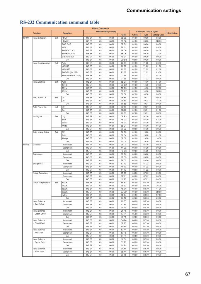
67
Communication settings
RS-232 Communication command table
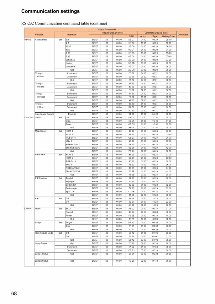
68
Communication settings
RS-232 Communication command table (continue)
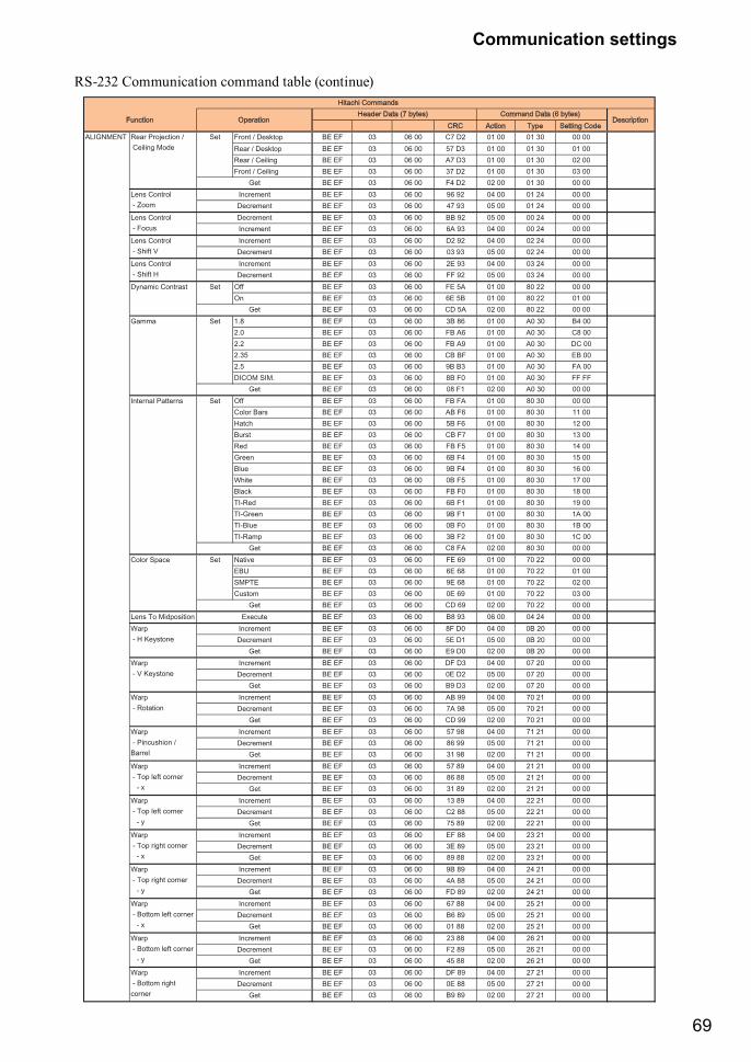
69
Communication settings
RS-232 Communication command table (continue)
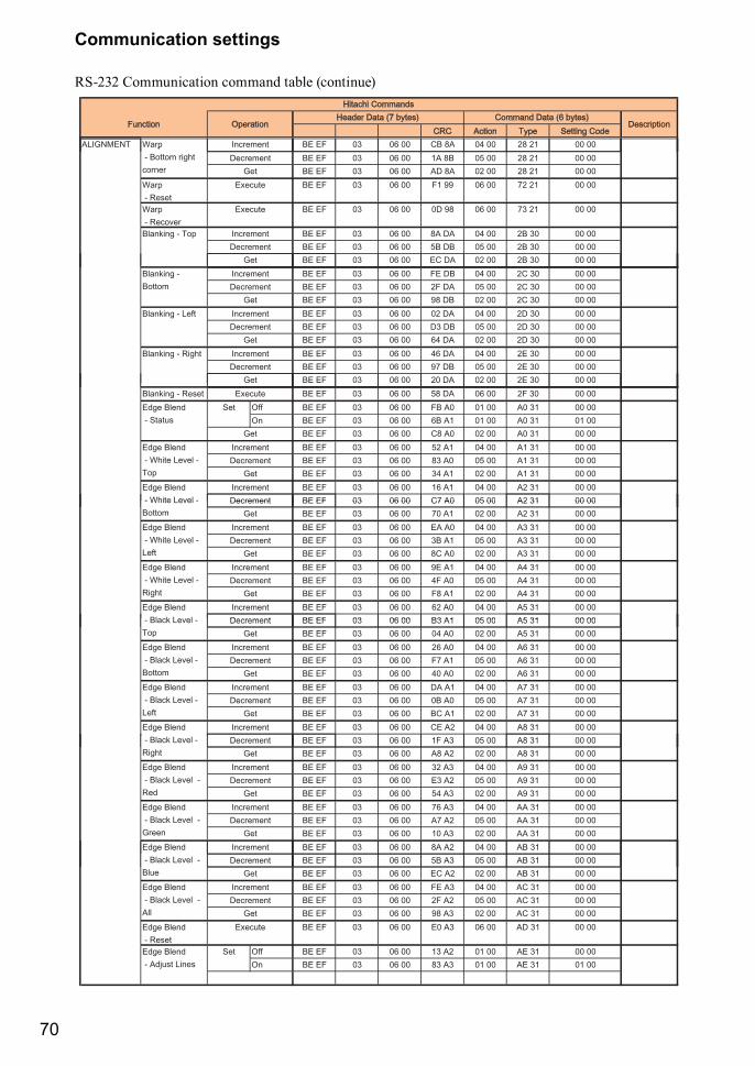
70
Communication settings
RS-232 Communication command table (continue)
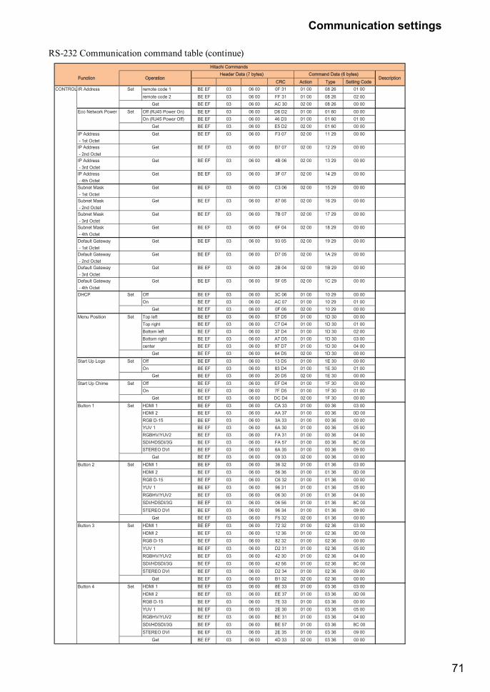
71
Communication settings
RS-232 Communication command table (continue)
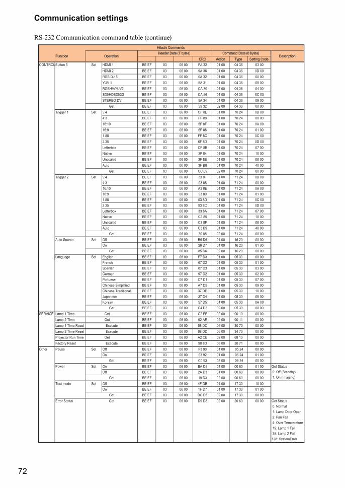
72
Communication settings
RS-232 Communication command table (continue)
73
Copyright informationCopyrightCopyright 2013. All rights reserved. No part of this publication may be reproduced, transmitted, transcribed, stored in a retrieva l system or translated into any language or computer language, in any form or by any means, electronic, mechanical, magnetic, optical, chemical, manual or otherwise, without the prior written permission of this company.
DisclaimerThis company makes no representations or warranties, either expressed or implied, with respect to the ������ ������ �� ���������" �������� �" �������> ������&���" �� ����� ��� �" ������� purpose. Further, this company reserves the right to revise this publication and to make changes from time to time in the contents hereof without obligation to notify any person of such revision or changes.
The illustrations in this manual are for illustrative purposes. They may differ slightly from your projector.
The reproduction, transfer or copy of all or any part of this document is not permitted without express written consent.
*DLP and Digital Micromirror Device (DMD) are trademarks of Texas Instruments. Others are copyrights of their respective companies or organizations.
*Registered trademarks of HDMI Licensing LLC in the United States and other countries.
All other trademarks are the properties of their respective owners.
Warranty and after-serviceIf an abnormal operation (such as smoke, strange odor or excessive sound) should occur, stop using the projector immediately. �������� �� ���&��� ������ ��� �� ��������> ��� ����� � �J���&����������> �� ��� through the suggested checks.If this does not resolve the problem, please consult your dealer or service company. They will tell you what warranty condition is applied.

74
DUKANE CORP AV SERVICE DEPT 2900 Dukane DriveSt Charles, IL 60174800-676-2487 / 630-762-4032 Fax [email protected] www.dukaneav.com
430-9010_User Manual v00