dui-vio: depth uncertainty incorporated visual inertial
TRANSCRIPT

DUI-VIO: Depth Uncertainty Incorporated Visual Inertial Odometrybased on an RGB-D Camera
He Zhang and Cang Ye, Senior Member, IEEE
Abstract— This paper presents a new visual-inertial odom-etry, term DUI-VIO, for estimating the motion state of anRGB-D camera. First, a Gaussian mixture model (GMM) to isemployed to model the uncertainty of the depth data for eachpixel on the camera’s color image. Second, the uncertaintiesare incorporated into the VIO’s initialization and optimizationprocesses to make the state estimate more accurate. In orderto perform the initialization process, we propose a hybrid-perspective-n-point (PnP) method to compute the pose changebetween two camera frames and use the result to triangulate thedepth for an initial set of visual features whose depth values areunavailable from the camera. Hybrid-PnP first uses a 2D-2DPnP algorithm to compute rotation so that more visual featuresmay be used to obtain a more accurate rotation estimate. It thenuses a 3D-2D scheme to compute translation by taking intoaccount the uncertainties of depth data, resulting in a moreaccurate translation estimate. The more accurate pose changeestimated by Hybrid-PnP help to improve the initializationresult and thus the VIO performance in state estimation. Inaddition, Hybrid-PnP make it possible to compute the posechange by using a small number of features with a knowndepth. This improves the reliability of the initialization process.Finally, DUI-VIO incorporates the uncertainties of the inversedepth measurements into the nonlinear optimization process,leading to a reduced state estimation error. Experimental resultsvalidate that the proposed DUI-VIO method outperforms thestate-of-the-art VIO methods in terms of accuracy and relia-bility
I. INTRODUCTION
Nowadays, robots have found applications in agriculture,manufacturing, mining and self-driving vehicles, as well asother areas such as surveillance, rescue, deep sea and evenspace exploration [1]. To operate autonomously, a robotneeds to map its environment and localize itself in the envi-ronment. This problem is generally known as simultaneouslocalization and mapping (SLAM). Visual SLAM (vSLAM)has gained extensive attention since the influential work [2]showing that vSLAM can run in real time on a personalcomputer. The state-of-the-art vSLAM methods have demon-strated their effectiveness with impressive results in variousapplications [3], [4]. Unfortunately, a vSLAM method cannotrecover the absolute scale of the environment due to the useof a single monocular camera. Also, they cannot reliablytrack the camera pose when the images are impacted byillumination change, low-texture scene, and/or motion blur.To tackle these issues, an inertial measurement unit (IMU)
This work was supported in part by the National Eye Institute (NEI) ofthe National Institute of Health under Award R01EY026275. The content issolely the responsibility of the authors and does not necessarily represent theofficial views of the funding agency. H. Zhang and C. Ye are with ComputerScience Department, Virginia Commonwealth University, Richmond, VA23284, USA. (e-mail: [email protected], [email protected]).
is coupled with the camera for scale deterministic poseestimation. In the robotics community, a navigation systemconsisting of a camera and an IMU is called a visual-inertialnavigation system (VINS) and the method to fuse the visualand inertial data for motion state estimation is termed visual-inertial odometry (VIO). Monocular-camera-based VINS hasbeen a popular solution [5] to robust motion estimation foran aerial vehicle (UAV) or handheld applications. However,a monocular VINS may fail to estimate the scale under somemotion conditions [6]. The scale problem can be eliminatedif a stereo camera [7], [8] or an RGB-D camera [9], [10]is used instead. For an RGB-D camera-based VIO, thereexists two approaches for state estimation. One is to usea visual odometry (VO) to compute the pose change byusing the depth data of the associated visual features andfuse the VO-estimated pose change with that of the IMU’spreintegration [9], [11]. Another is to compute the visualfeatures’ 3D positions from the depth measurements andminimize the features’ reprojection residuals together withthe IMU’s preintegration residuals by an iterative process[10], [12]. The existing methods using either scheme assumean accurate depth measurement and treats the depth value ofa visual feature as a constant in the iterative optimizationprocess [10], [12]. However, the depth measurement of anRGB-D camera may incur a large uncertainty, which canlead to a large state estimation error if it is not taken intoaccount.
In this work, we introduce a new VIO method, call DUI-VIO based on an RGB-D camera. It models the uncertaintiesfor the depth and inverse depth measurements of the cam-era by a Gaussian mixture model (GMM) and incorporatethe estimated uncertainties into the VIO’s initialization andoptimization processes to improve the accuracy of motionstate estimation. A new PnP method is developed to providea more accurate estimate for the VINS’ transformationmatrix for a more reliable VIO initialization. The methoddecouples the rotation and translation computations becausethe computation of the rotation does not require the depthdata of the visual features but that of the translation does.This way, more visual features (w/ and w/o depth data) areused to compute a more accurate rotation, based which thetranslation is determined. This results in a more accurateestimate on the transformation matrix. The superiority of theproposed DUI-VIO has been validated by our experiments.
II. RELATED WORK
In [9] an extended Kalman filter (EKF) is employed forlocalization by integrating the pose estimates by an RGB-D
2020 IEEE/RSJ International Conference on Intelligent Robots and Systems (IROS)October 25-29, 2020, Las Vegas, NV, USA (Virtual)
978-1-7281-6211-9/20/$31.00 ©2020 IEEE 5002
and an IMU. The EKF uses the IMU-estimated pose changeto generate state prediction and treats the pose estimated bya visual SLAM as the observation. The innovation is usedto update the state. Laidlow et al. [11] propose a denseRGB-D-inertial SLAM method. The method combines theresiduals of the photometric per-pixel measurements, geo-metric point-to-plane distances, and IMU preintegration in acost function. It then estimates the system’s optimal motionstate by minimizing the cost function by a Gauss-Newtoniterative process. However, this method requires a GPU toprocess the dense camera data for real-time computationand is thus unsuitable to a resource-limited mobile platform[13], [14], [15]. Guo and Roumeliotis [16] propose a sparsefeature-based RGBD-IMU calibration method. They analyzethe observability of the VINS’ state variables and designa strategy that updates the state variable only along theirobservable directions. The strategy results in a better filterconsistency. Due to the use of sparse visual features, themethod is computationally effective and does not requireGPU speedup. But it does not explicitly estimate the VINS’initial state, which is crucial to the proper function of thesubsequent state estimation process [17]. As revealed bythe benchmark comparison study [15], VINS-Mono [5] hasthe most accurate result because of its robust initializationprocess. However, the initialization requires sufficient IMUexcitement, without which an inaccurate scale estimationmay be resulted, causing VINS-Mono to ill-perform. RecentRGB-D camera-based VIO methods [10], [12] address thisissue by using the camera’s depth data to obtain the absolutescale. The method proposed by Ling et al. [12] extractsORB features [4] and uses a 3D-3D-perspective n-point(PnP) method [18] to compute the visual structure (includingcamera poses and feature positions). It then aligns theestimated camera poses with the IMU integration to estimatethe VINS’ initial state, including the IMU’s poses, velocities,bias, and gravity direction. Shan et al. [10] use corner points[19] and employ a 3D-2D-PnP [20] method to build thevisual structure. After initialization, their method estimatesthe VINS’ motion state and the inverse depths of the trackedvisual features through a nonlinear optimization process. Ifa feature’s depth is provided by the RGB-D camera, theinverse depth value is treated as a constant. However, thereality is that depth measurement, particularly for a pointnear the edge of an object, may contain significant noise [21],making the value inaccurate. This underscores the need toestimate the uncertainty of the visual feature’s inverse depthand factor it into the state estimation. Differing from theprevious methods, our proposed DUI-VIO method explicitlycomputes the uncertainty of the RGB-D camera’s depth dataand incorporates the uncertainty into the initialization andnonlinear optimization processes for motion state estimation.
III. STRUCTURE CORE AND COORDINATE SYSTEMS
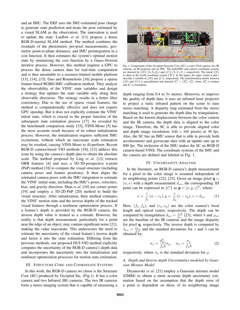
In this work, the RGB-D camera we chose is the StructureCore (SC) produced by Occipital Inc. (Fig.1). It has a colorcamera and two Infrared (IR) cameras. The two IR camerasform a stereo imaging system that is capable of measuring a
Fig. 1: Components of the Occipital Structure Core (SC): a color VGA camera, two IRcameras, an IR projector and an IMU. The body/IMU and camera coordinate systemsare denoted by {B} (XbYbZb) and {C} (XcYcZc), respectively. The initial {B}is taken as the world coordinate system {W}. In this paper, the super scripts b and cdescribe a variable in {B} and {C}, respectively. The transformation matrix between{B} and {C} is precalibrated and denoted T bc = [Rbc; tbc], where Rbc is rotationand tbc is translation.
depth ranging from 0.4 to 5+ meters. Moreover, to improvethe quality of depth data, it uses an infrared laser projectorto project a static infrared pattern on the scene to easestereo matching. A disparity map estimated from the stereomatching is used to generate the depth data by triangulation.Based on the known displacement between the color cameraand the IR camera, the depth data is aligned to the colorimage. Therefore, the SC is able to provide aligned colorand depth image (resolution: 640 × 480 pixels) at 30 fps.Also, the SC has an IMU sensor that is able to provide bothaccelerometer and gyroscope data with an update rate up to800 fps. The inclusion of the IMU makes the SC an RGB-Dcamera-based VINS. The coordinate systems of the IMU andthe camera are defined and labeled in Fig. 1.
IV. UNCERTAINTY ANALYSIS
In the literature, an RGB-D camera’s depth measurementfor a pixel in the color image is assumed independent ofits neighboring points [22], [23]. Given an image pixel q =(u, v) with a depth measurement duv , the corresponding 3Dpoint can be expressed in {C} as p = [x, y, z]T , where:
x =z
fx(u− cx), y =
z
fy(v − cy), z = duv (1)
Here, (fx, fy), and (cx, cy) are the color camera’s focallength and optical center, respectively. The depth can becomputed by triangulation duv = fxb
ρuv[23], where b and ρuv
are the baseline of the IR cameras and the image disparityfor pixel q, respectively. The inverse depth is computed byλuv = ρuv
fxband the standard deviations for z and λ can be
obtained by:
σz =d2uv
fxbσρ, σλ =
σρfxb
(2)
respectively, where σρ is the standard deviation for ρ.
A. Depth and Inverse depth Uncertainties modeled by Gaus-sian Mixture Model
Dryanovski et al. [21] employ a Gaussian mixture model(GMM) to obtain a more accurate depth uncertainty esti-mation based on the assumption that the depth error ofa point is dependent on those of its neighboring image
5003

pixels. They also assume that the coordinates of a pixelhave Gaussian distributed errors. In this work, we use theGMM [21] to compute the uncertainties of the depth andthe inverse depth measurements. Specifically, assuming theu and v of are independent random variables with normaldistributions N (µu, σu) and N (µv, σv), respectively, andthe raw measurement z for pixel (u, v) is normally dis-tributed N (µz, σz) where µz = duv and σz is computedby equation (2), we define a random variable z as a mix-ture of the z values for all pixels within a local windowS = {(i, j) : i ∈ [µu − 1, µu + 1], j ∈ [µv − 1, µv + 1]}.The weight of the mixture wij is computed by:
wij = exp
(−(
(i− u)2
2σ2u
+(j − v)2
2σ2v
)− log
(η(dij − duv)2
σ2zσ
2S
+ 1
))(3)
where dij is µz for pixel (i, j) and η is a scale factor. σ2S
represents the variance of the depth measurements in thelocal window S. The first part of wij represents spatialcorrelation while the second part describes the correlationrelated to depth similarity. Then, the mean and variance ofthe resulting Gaussian mixture are computed as follows:
µz =
∑i,j wijdij∑i,j wij
, σ2z =
∑i,j wij(d
2ij + σ2
zij )∑i,j wij
− µ2z (4)
where σzij is σz for pixel (i, j). For the inverse depth λ,we assume the raw measurement λ at (u, v) is also normallydistributed N (µλ, σλ), where µλ = 1
duvand σλ is computed
according to equation (2). Notice that σλ is constant thatis independent of the location (u, v) [23]. We define λ asa mixture of the λ variables for those pixels in S, and themean and variance of the Gaussian mixture for inverse depthλ are computed as:
µλ =
∑i,j
w′ij
dij∑i,j w
′ij
, σ2λ
=
∑i,j w
′
ij(1d2ij
+ σ2λ)∑
i,j w′ij
− µ2λ
(5)
where w′
ij is similar to equation (3) by replacing dij , duv ,σ2z and σ2
S with 1dij
, 1duv
, σ2λ and σ′2S , respectively. σ′2S is the
variance of the inverse depth measurements for those pixelsin the local window S.
B. 3D covariance matrix
Deriving from equation (1) and replacing z with z, the 3Dcovariance matrix Σp of a point p in the camera coordinatesystem can be computed by:
Σp =
σ2x, σxy, σxzσyx, σ
2y, σyz
σzx, σzy, σ2z
(6)
where σ2x =
σ2z(µ′
u)2+σ2ug
f2x
, σ2y =
σ2z(µ′
v)2+σ2vg
f2y
, σxz = σzx =
σ2zµ
′u
fx, σyz = σzy =
σ2zµ
′v
fy, σxy = σyx =
σ2zµ
′uµ
′v
fxfywith µ′u =
µu− cx, µ′v = µv− cy , g = µ2z +σ2
z . The approximations ofthe mean and covariance of the 3D point p are used in theinitialization phase of the DUI-VIO method.
V. RGB-D CAMERA-BASED VIOThe proposed DUI-VIO consists of two components: fron-
tend feature tracking and backend state estimation. Similar to[5] and [10], the feature tracking part extracts visual features[19] from an image and tracks them across images by usingKLT [24]. A fundamental-matrix-based RANSAC process isimplemented to remove the outliers. It also selects keyframesbased on the average parallax difference. If the averageparallax of the tracked features between the current frameand the latest keyframe is larger than a threshold (10 pixels),this frame is treated as a keyframe. The tracked features inall frames are passed to the backend process to estimate theVINS’ motion state. The backend state estimation starts witha sophisticated initialization process and then proceeds witha nonlinear optimization process for state estimation.
A. Initialization
The initialization procedure first implements a vision-onlySfM to estimate the camera poses and feature positions. Toreduce computational complexity, we process visual-inertialdata inside a sliding window. . The details of the initializationare illustrated in Algorithm 1. At first, feature correspon-dences are checked between the latest camera frame FM andall previous frames. If enough parallax (more than 30 pixels)is found between Fl and FM , we estimate the pose changeT between them by using a PnP method (line A1.3-4). Flis selected as reference frame and T is used to triangulateall features (with no depth data from the depth camera)observed in these two frames (line A1.6). The output ofthe triangulation is a set of 3D feature points denoted asΓ which is represented in the reference frame. Given Γ, weestimate the poses of all other frames in the sliding windowby the iterative procedure (Function PnPAllFrames inline A1.12): 1) given (Γ, Sp), employ the OpenCV functionsolvePnP to estimate the pose of the current frame i;2) triangulate the features at Fi and add them to Γ; 3)repeat steps 1 and 2 for the next frame until all frames areprocessed. Next, a global bundle adjustment is employedto optimize the camera poses by minimizing the featurereprojection residuals (line A1.16). Finally, visual-inertialalignment is applied to estimate the IMU’s poses, velocities,biases and gravity direction by aligning the camera poseswith the IMU pre-integration (line A1.17). More detailsabout visual-inertial alignment can be found in [10].
The success of the function PnPAllFrames depends onthe accuracy of Γ which is estimated by feature triangulation(line A1.6). The accuracy of the triangulation is determinedby the pose change estimate T . Therefore, the reliabilityof the initialization is dependent on the accuracy of T(line A1.4). Differing from VINS-Mono [5] that computethe camera’s rotation and translation by the 2D-2D-PnPmethod [25], VINS-RGBD [10] employs the 3D-2D-PnPmethod (called EPnP) [20] to compute the pose changesince depth data are available. However, EPnP tends to resultin a larger rotation error because: 1) a depth measurementerror (quadratically increases with depth) may result in areprojection error that is larger than the image noise; 2) a
5004

pose change computed from a low number of features withdepth data may be inaccurate. To tackle these issues, wepropose a new PnP method called Hybrid-PnP as illustratedin Algorithm 2. First, we employ the 2D-2D-PnP method[25] ] to estimate the rotation (line A2.2) by using all features(both w/ and w/o depth data). Meanwhile, the inliers of the2D features are obtained. After selecting the inliers withdepth measurement (line A2.6), we estimate the translationof the camera by minimizing the reprojection error of thede-rotated features (line A2.10).
Specifically, given the rotation Rji between two frames iand j, we can estimate the translation tji using the followingstrategy. Assuming M features {pik,p
jk}, for k = 1...M ,
observed in frames Fi and Fj , where pik = [Xik, Y
ik , Z
ik]T is
the coordinates of feature k in Fi, pjk = [Xj
k, Yj
k, 1]T is thenormalized coordinates of feature k in Fj where z is one.Assume the depth in Fj is zjk, we have:
zjkpjk = Rjipik + tji (7)
Equation (7) has three rows. Substituting zjk in the third rowinto the first and second rows results in:
(R1 −Xj
kR3)pik + t1 −Xj
kt3 = 0
(R2 − Yj
kR3)pik + t2 − Yj
kt3 = 0(8)
where Ri and ti (i = 1, 2, 3) are the i-th row of Rjiand tji, respectively. Therefore each feature can providea 2-dimensional constraint and at least two feature pointsare needed to estimate tji. Since we can compute the 3Dcovariance of a feature point, we use a weighting schemeto combine the constraints resulted from different featurepoints. For feature point k, the residual vector of tji is givenby:
rk = Wk(Aktji − bk) (9)
where
Ak =
[1, 0,−Xj
k
0, 1,−Y jk
],bk =
[(X
j
kR3 −R1)pik(Y
j
kR3 −R2)pik
],
Wk =
1√JxΣpi
kJTx, 0
0, 1√JyΣpi
kJTy
, Jx = R1−Xj
kR3, Jy = R2−Yj
kR3
Σpikis the covariance of the 3D point pik in Fi and it is
computed by Eq. (6). The optimal translation that minimizesthe residual vectors of all tracked features can be obtainedby solving the following optimization problem:
t∗ji = arg mintji
M∑k=1
||rk||2 (10)
Eq. (10) can be solved by the Levenberg–Marquardt (LM)algorithm (line A2.10). Finally, the pose estimation [Rij , tji]is further improved by using the Gaussian Newton (GN)scheme (line A2.11). Because the LM-resulted solution isquite accurate, GN only takes no more than three iterations.By incorporating the uncertainty of the camera’s depth data,a more accurate translation is obtained.
Algorithm 1: Initializationinput : camera frames F={Fi, i = 1...M}, IMU
preintegration Pu, 2D feature setSp = {pti, i = 1...L} and depth setSd = {di, i = 1...K} corresponding topoints in Sp with depth measurement
output: poses, velocities and biases of IMU at F andgravity direction
1 Γ← ∅, Pf ←{T0}2 for l← 1 to M − 1 do3 if largeDisparityBetween(Fl, FM , Sp) then4 [T , success] = Hybrid-PnP(Fl, FM , Sp, Sd)5 if success is true then6 Γ = triangulation(T,Fl,FM , Sp, Sd)7 Pf ← Pf ∪ T8 break9 end
10 end11 end12 [Γ, Pf , success] = PnPAllFrames(Γ, Pf , F , Sp, Sd)13 if success is false then14 return [ ]15 end16 [Pf ] = bundleAdjustment(Γ, Pf , Sp)17 [Bf , Vf , g] = visualIniertialAlignment(Pf , Pu)18 return [Pf , Bf , Vf , g]
Algorithm 2: Hybrid-PnPinput : camera frames Fi and Fj , Sp and Sdoutput: pose change estimation Tji to transform a
point from Fi to Fj1 Θ= findMatchedFeatures(Fi, Fj , Sp)2 [Rji,Θ] = 2D-2D-PnP(Θ)3 if Θ == ∅ then4 return [ , false]5 end6 Θ = findInliersWithDepth(Θ, Sd)7 if Θ == ∅ then8 return [ , false]9 end
10 tji = translationEstimate(Rji, Θ)11 [Rji, tji] = GaussianNewton(Rji, tji, Θ)12 return [[Rji, tji], true]
B. State Estimator
After initialization, a sliding window-based nonlinearoptimization process is employed for state estimation.The full state vector in the sliding window is definedas χ = {x1,x2, ...,xn, λ1, λ2, ..., λm}, where xi ={twbi ,v
wbi,qwbi ,ba,bg
}(i ∈ [1, n]) is the IMU’s motion state
(translation, velocity, rotation, accelerometer bias and gyro-scope bias) at the time when the ith keyframe is captured. nis the size of the sliding window (n = 10 in this work) andm is the total number of features in the sliding window. λk
5005

(k = 1...m) is the estimate for the inverse distance of the kthfeature from its first observation. Similar to [5] and [10], weestimate the state vector χ by minimizing the sum of priorand the Mahalanobis norm of all measurement residuals as:
χ∗ = arg minχ
{||pr||2 +
∑j
||urj ||2 +∑(k,j)
ρ(||prkj ||2)
+∑(k,j)
ρ(||pdrkj ||2) +∑k
||drk||2}
(11)
where ρ() is the Huber loss function [26]. pr, urj , andprkj represent the residuals for the prior information frommarginalization, IMU preintegration (between keyframes j−1 and j) and feature reprojection, respectively. Their defini-tion are referred to [5]. The other residuals, pdrkj and drkare defined as follows by using the inverse depth.
1) computation of pdrkj: By using a normalized coordi-nate system, the kth feature point that was first observed atkeyframe i is denoted by pik = [X
i
k, Yi
k, 1]T . Its estimatedinverse depth is λk. Note that we drop subscript k forsimplicity from now on. If the feature point is trackedonto keyframe j, the mean (µλ) and variance (σ2
λ) of its
inverse depth measurement at keyframe j can be computedby Eqn. (5). The feature point can be expressed in Cj (i.e.,the camera coordinate system for keyframe j) as pj =
[Xj , Yj , Zj ]T = Rji
pi
λ+ tji, where Rji and tji are the
rotation matrix and translation from Cj to Ci. By translatingpj into its normalized form, we can compute the residual
vector by: pdrkj =√
Σ−1cj
[XjZj−Xj ,
YjZj− Y j , 1
Zj− µλ
]Twhere Σcj is the measurement covariance that is defined byΣcj = diag(
σ2τ
f2x,σ2τ
f2y, σ2λ). στ is the image noise and it is set
to 1.5 pixels in this work.2) computation of drk: If the inverse depth measurement
for the kth feature (observed at the ith keyframe) is availablefrom the camera’s depth data, its mean (µλ) and variance(σ2λ
) can be computed by Eqn. (5). Therefore, the drk is
computed by drk =λ−µλσλ
.The above residuals pdrkj and drk encode the measure-
ments of the inverse depth based on GMM. The inversedepth measurement is tightly incorporated into the nonlinearoptimization process to make more accurate state estimation.The nonlinear optimization problem (11) is solved by usingthe Ceres solver [27].
VI. EXPERIMENT
A. PnP Comparison
We compared the proposed Hybrid-PnP with the state-of-the-art EPnP [20] by simulation. We produced 1000 synthetic2D features in a 640× 480 image by using a virtual camerawith a focal length fx = fy = 525 and a principal pointat (320, 240). These features’ depth measurementwas weregenerated by using a uniform distribution in the range [2, 5]meters and their 3D positions were computed accordingly.We then changed the camera viewpoint by applying a rotationRtrue and a translation ttrue to the camera’s coordinatesystem. By reprojecting the 3D feature points onto the new
Fig. 2: PnP Comparison. Top: Reprojection Error; Middle: Translation Error; Bottom:Rotation Error.
Fig. 3: Handheld and Mobile Robot for data collection
camera image plane, we obtain their observations in thenew camera coordinate system. A zero mean Gaussian noise(σu = 1, σv = 1) was then added to the coordinates of thefeatures. Also, a Gaussian noise that quadratically increaseswith depth [23] was added to the depth measurements.Given the feature matches between the two camera frames,we employed Hybrid-PnP and EPnP methods to computethe pose change estimate, denoted as [Rest, test]. We thencomputed the relative angular and translation error for theestimation. The angular error eθ and the translation error etcan be computed by Re = R−1
trueRest and et = ||ttrue−test||,respectively. ttrue is set to [0.2, 0.05, 0.3]T , while the rotationRtrue is generated by rotating the camera by 7, 5, and10 degrees around the x, y, and z axis, respectively. Wecarried out nine tests and in each test we independently ranthe hybrid-PnP and EPnP methods w/ and w/o GN for 500times to estimate the pose changes. In each test, we assumedthat at least 30 inliers can be found and only a portion ofthese inliers have depth measurements. In the 2D-2D-PnPfunction (line A2.2) of the Hybrid-PnP, we used 30 featuresfor rotation estimation and we used N (N <= 30) featuresfor translation estimation. We also used these N features in
5006

TABLE I: Results on the Lab Datasets: RMSE in meters of the estimated trajectoryof each VIO method. In each row, the best result is bolded. TL - Trajectory Length,X – Failed to initialize or to converge in the state estimator
Dataset VINS-Mono
Vins-Fusion
VINS-RGBD
DUI-VIO
TL (m)
H1 0.142 0.178 0.137 0.109 15H2 0.175 0.324 0.431 0.151 17H3 0.236 0.224 0.116 0.123 23H4 0.619 0.827 0.638 0.602 30H5 0.373 0.873 0.378 0.372 80H6 0.706 0.676 0.725 0.549 84R1 X X X 0.258 15R2 X X 1.174 0.179 28R3 0.402 X 0.308 0.191 25R4 0.971 X X 0.134 43
EPnP to compute both rotation and translation. This is tosimulate the real cases that some of the matched features donot have depth measurements. In Fig. 2, we first show thesum of the feature reprojections given the estimated trans-formation by Hybrid-PnP and EPnP. It shows that Hybrid-PnP consistently generate much smaller feature reprojectionerror than EPnP. Then the mean of [eθ, et] for each methodare plotted. We also compare the errors of Hybrid-PnP andEPnP after the refinement by a GN optimization process [20].From the result shown in Fig. 2, we can see that Hybrid-PnPw/ or w/o GN produced a much smaller rotation error thanthe EPnP counterparts. Also, the translation error of Hybrid-PnP with GN is the smallest. Finally, Hybrid-PnP can provideaccurate pose change estimation even when the number offeatures with depth is very small.
B. DUI-VIO Evaluation
In this section, we carried out thirteen experiments tocompare the pose estimation performance of the proposedDUI-VIO with the state-of-the-art VIO methods: VINS-Mono [5], VINS-Fusion [7], and VINS-RGBD [10]. Ten ofthe experiments were conducted in our laboratory and therest were in the hallways of the East Engineering Buildingon campus. The pose estimation results were summarizedbelow.
1) Laboratory Experiments: Six of the ten experimentswere conducted in our laboratory by handholding the SC(Fig. 3) and walking in a looped trajectory at a normal walk-ing speed 0.6m/s. For the first three experiments we movedthe camera smoothly, while for the other three, we rotated thecamera heavily on purpose. The last four experiments werecarried out by installing the camera on a wheeled robot (Fig.3) and driving the robot to move on a looped trajectory at aspeed 0.2m/s. At the beginning of each experiment using thewheeled robot, we first handheld and rotated the SC for aboutfive seconds to excite the visual-inertial system to allow fora good system initialization. Then we installed the SC on therobot and drove the robot for the experiment. By using theground truth trajectory generated by our OptiTrack motioncapture system, we calculated the absolute pose error foreach point on the trajectories generated by DUI-VIO, VINS-Mono, VINS-Fusion, and VINS-RGBD. Table I summarizes
TABLE II: EPEN (%) statistics for each method, the best result if bolded. TL -Trajectory Length, X – Failed to initialize
Dataset VINS-Mono
Vins-Fusion
VINS-RGBD
DUI-VIO
TL (m)
H1 1.54 2.5 2.1 1.42 185H2 1.69 1.33 X 0.85 174H3 1.86 3.85 X 1.03 180Mean 1.7 2.56 X 1.1 180
the results, the smallest error was highlighted in boldface. Ascan be seen from the table, our proposed algorithm succeededin every experiment while the other methods failed in mostof the experiments with the wheeled robot. In addition, DUI-VIO has the smallest RMSE in nine of the ten experimentsand its RMSE is only slightly larger than that of VINS-RGBD in one experiment. This demonstrates that DUI-VIOhas a much more accurate pose estimation than the othermethods. Fig. 4. compares the trajectories generated by thefour methods for some of the experiments.
2) Real World Experiments: To validate the DUI-VIOin the real world, we carried out three experiments byhandholding the SC and walking in a looped trajectory (i.e.,returning to the starting point) in the hallways of the EastEngineering Building. The Endpoint Position Error Norm(EPEN) in percentage of the path-length is use as the metricfor pose estimation accuracy. The results are tabulated inTable II. It can be seen that DUI-VIO achieved a smallerEPEN than the other methods in all of the four experiments.On average, DUI-VIO reduces the EPEN by 35.3%, 57%,and 47.6% compared to VINS-Mono, VINS-Fusion, andVINS-RGBD, respectively. Fig. 5 compares the trajectoriesestimated by the four methods, from which it can be observedthat DUI-VIO resulted in a more accurate trajectory. In twoof the experiments, we observed that VINS-RGBD failed inits initialization step. The reason was that it failed to findenough 3D feature points for pose change estimation. Incontrast, DUI-VIO could reliably initialized itself and thusachieved more accurate pose estimation results.
VII. CONCLUSION
We proposed a new VIO method—DUI-VIO—for stateestimation for an RGB-D camera-based VINS. We employedGMM to estimate the uncertainties for the depth and theinverse depth measurement from an RGB-D camera. Themodeled uncertainties are incorporated into the initializationand nonlinear optimization processes of the VIO to improvereliability and accuracy. In the initialization process, we alsoproposed a Hybrid-PnP to reliably boost the initializationprocess of the DUI-VIO. We carried out extensive experi-ments to show that DUI-VIO outperforms the state-of-the-artin terms of reliability and accuracy.
REFERENCES
[1] M. Ben-Ari and F. Mondada, “Robots and their applications,” inElements of Robotics. Springer, 2018, pp. 1–20.
[2] A. J. Davison, I. D. Reid, N. D. Molton, and O. Stasse, “Monoslam:Real-time single camera slam,” IEEE transactions on pattern analysisand machine intelligence, vol. 29, no. 6, pp. 1052–1067, 2007.
5007

Fig. 4: Top: Trajectory Comparison for Handheld datasets(H1-H4) in the Lab. Start point is labeled by dark solid circle in each dataset; Bottom: Trajectory Comparison forRobot datasets (R1-R4) in the Lab
Fig. 5: Trajectory Comparison for the Corridor datasets
[3] J. Engel, T. Schops, and D. Cremers, “Lsd-slam: Large-scale directmonocular slam,” in Proc. of European conference on computer vision.Springer, 2014, pp. 834–849.
[4] R. Mur-Artal, J. M. M. Montiel, and J. D. Tardos, “Orb-slam: aversatile and accurate monocular slam system,” IEEE transactions onrobotics, vol. 31, no. 5, pp. 1147–1163, 2015.
[5] T. Qin, P. Li, and S. Shen, “Vins-mono: A robust and versatile monoc-ular visual-inertial state estimator,” IEEE Transactions on Robotics,vol. 34, no. 4, pp. 1004–1020, 2018.
[6] K. J. Wu, C. X. Guo, G. Georgiou, and S. I. Roumeliotis, “Vins onwheels,” in Proc. of IEEE Int. Conf. on Robotics and Automation(ICRA), 2017, pp. 5155–5162.
[7] T. Qin, J. Pan, S. Cao, and S. Shen, “A general optimization-basedframework for local odometry estimation with multiple sensors,” arXivpreprint arXiv:1901.03638, 2019.
[8] S. Leutenegger et al., “Keyframe-based visual-inertial slam usingnonlinear optimization,” in Proc. of Robotis Science and Sys., 2013.
[9] N. Brunetto et al., “Fusion of inertial and visual measurements for rgb-d slam on mobile devices,” in Proceedings of the IEEE InternationalConference on Computer Vision Workshops, 2015, pp. 1–9.
[10] Z. Shan, R. Li, and S. Schwertfeger, “Rgbd-inertial trajectory estima-tion and mapping for ground robots,” Sensors, vol. 19, no. 10, p. 2251,2019.
[11] T. Laidlow, M. Bloesch, W. Li, and S. Leutenegger, “Dense rgb-d-inertial slam with map deformations,” in Proc. of IEEE/RSJ Int. Conf.on Intelligent Robots and Systems (IROS), 2017, pp. 6741–6748.
[12] Y. Ling, H. Liu, X. Zhu, J. Jiang, and B. Liang, “Rgb-d inertialodometry for indoor robot via keyframe-based nonlinear optimization,”in Proc. of IEEE Int. Conf. on Mechatronics and Automation (ICMA),2018, pp. 973–979.
[13] M. Li and A. I. Mourikis, “Vision-aided inertial navigation forresource-constrained systems,” in Proc. of IEEE/RSJ InternationalConference on Intelligent Robots and Systems, 2012, pp. 1057–1063.
[14] H. Zhang and C. Ye, “An indoor navigation aid for the visuallyimpaired,” in Proc. of IEEE International Conference on Robotics andBiomimetics (ROBIO), 2016, pp. 467–472.
[15] J. Delmerico and D. Scaramuzza, “A benchmark comparison ofmonocular visual-inertial odometry algorithms for flying robots,” inProc. of IEEE International Conference on Robotics and Automation(ICRA), 2018, pp. 2502–2509.
[16] C. X. Guo and S. I. Roumeliotis, “Imu-rgbd camera 3d pose estima-tion and extrinsic calibration: Observability analysis and consistencyimprovement,” in Proc. of IEEE International Conference on Roboticsand Automation, 2013, pp. 2935–2942.
[17] H. Zhang, L. Jin, H. Zhang, and C. Ye, “A comparative analysis ofvisual-inertial slam for assisted wayfinding of the visually impaired,”in IEEE Winter Conf. on Applications of Computer Vision (WACV),2019, pp. 210–217.
[18] D. Nister, O. Naroditsky, and J. Bergen, “Visual odometry,” in Pro-ceedings of IEEE Computer Society Conference on Computer Visionand Pattern Recognition, vol. 1, 2004, pp. I–I.
[19] J. Shi et al., “Good features to track,” in Proceedings of IEEE conf.on computer vision and pattern recognition, 1994, pp. 593–600.
[20] V. Lepetit, F. Moreno-Noguer, and P. Fua, “Epnp: An accurate o (n)solution to the pnp problem,” International journal of computer vision,vol. 81, no. 2, p. 155, 2009.
[21] I. Dryanovski, R. G. Valenti, and J. Xiao, “Fast visual odometry andmapping from rgb-d data,” in Proc. of IEEE International Conferenceon Robotics and Automation, 2013, pp. 2305–2310.
[22] D. Gutierrez-Gomez, W. Mayol-Cuevas, and J. J. Guerrero, “Inversedepth for accurate photometric and geometric error minimisationin rgb-d dense visual odometry,” in Proc. of IEEE InternationalConference on Robotics and Automation (ICRA), 2015, pp. 83–89.
[23] A. Concha and J. Civera, “Rgbdtam: A cost-effective and accuratergb-d tracking and mapping system,” in Proc. of IEEE/RSJ Int. Conf.on Intelligent Robots and Systems (IROS), 2017, pp. 6756–6763.
[24] B. D. Lucas, T. Kanade et al., “An iterative image registrationtechnique with an application to stereo vision.”
[25] R. Hartley and A. Zisserman, Multiple view geometry in computervision. Cambridge university press, 2003.
[26] P. J. Huber, “Robust estimation of a location parameter,” in Break-throughs in statistics. Springer, 1992, pp. 492–518.
[27] S. Agarwal, K. Mierle et al., “Ceres solver,” 2012.
5008