ductility of frp–concrete systems: investigations at...
TRANSCRIPT

Construction and Building Materials 49 (2013) 915–925
Contents lists available at SciVerse ScienceDirect
Construction and Building Materials
journal homepage: www.elsevier .com/locate /conbui ldmat
Ductility of FRP–concrete systems: Investigations at different lengthscales
0950-0618/$ - see front matter � 2012 Elsevier Ltd. All rights reserved.http://dx.doi.org/10.1016/j.conbuildmat.2012.10.017
⇑ Corresponding author.E-mail address: [email protected] (O. Büyüköztürk).
Oguz Gunes a, Denvid Lau b, Chakrapan Tuakta c, Oral Büyüköztürk d,⇑a Department of Civil Engineering, Cankaya University, Ankara, Turkeyb Department of Civil and Architectural Engineering, City University of Hong Kong, Hong Kong, Chinac Department of Civil Engineering, Kasetsart University, Bangkok, Thailandd Department of Civil and Environmental Engineering, Massachusetts Institute of Technology, Cambridge, MA, USA
h i g h l i g h t s
" Ductility plays an important role in earthquake resistant design of structures." Environmental factors may adversely affect the ductility due to premature failure." Characterization of ductility at different length scales is described." Discussion covers from the continuum regime to the atomistic level.
a r t i c l e i n f o
Article history:Available online 3 January 2013
Keywords:DuctilityConcreteFRPDebondingFractureMoistureTemperatureMulti-scale
a b s t r a c t
Fiber reinforced polymer (FRP) materials have been increasingly used in the last two decades to improvevarious structural characteristics of reinforced concrete (RC) bridges, buildings and other structures. Duc-tility of the resulting FRP–concrete system plays an important role in structural performance, especiallyin certain applications such as earthquake resistant design of structures, where ductility and energy dis-sipation play a vital role. Wrapping RC columns with FRP has been shown to generally result in significantincrease in ductility due to the confinement of concrete by the FRP. Other applications such as flexuralstrengthening of beams involve tradeoffs between ductility and the desired load capacity. Furthermore,environmental factors may adversely affect the FRP–concrete bond raising concerns about the ductility ofthe system due to possible premature failure modes. Characterization of these effects requires the use ofmore involved mechanics concepts other than the simple elastic or ultimate strength analyses. This paperfocuses on characterizing ductility of the FRP–concrete systems at different length scales using a com-bined experimental/computational mechanics approach. Effects of several parameters on ductility,including constituent material properties and their interfaces, FRP reinforcement geometry at themacro- and meso-level, and atomistic structure at the molecular level are discussed. Integration of thisknowledge will provide the basis for improved design strategies considering the ductility of FRP–concretesystems from a global as well as local perspective including interface bond behavior under variousmechanical and environmental conditions.
� 2012 Elsevier Ltd. All rights reserved.
1. Introduction places increased emphasis on the deformation and ductility
Fiber reinforced polymer (FRP) composite materials have beenincreasingly used to improve the load capacity and serviceabilityof reinforced concrete (RC) members and structures in the lasttwo decades. Despite many favorable properties of FRP compositesthat encourage their use in conjunction with RC structures, a keyconcern is their typical brittle failure following a linearly elasticstress–strain behavior [1]. The current transition in design codestowards performance-based design and evaluation procedures
behavior of structures for satisfactory structural performance.Hence, accurate assessment of the ductility characteristics ofFRP–concrete systems at different scales as affected by majorinfluential factors is a necessity to ensure their safety throughoutthe intended service life.
This paper focuses on the ductility of FRP–concrete systemsbased on investigations ranging from the structural- to nano-scaleinvolving atomic-scale simulations. The paper begins with the def-inition and significance of ductility in the design and evaluation ofnew and existing structures followed by a discussion of the ductil-ity characteristics of FRP–concrete systems at different scales as af-fected by various factors. The scope is limited to use of ‘FRP as

916 O. Gunes et al. / Construction and Building Materials 49 (2013) 915–925
external reinforcement in concrete’, which is one of the four majortypes of FRP–concrete systems defined in the relevant ACI 440publication [2]. The investigations at the structural scale are pre-sented from a seismic performance perspective due to greateremphasis on ductility as a performance measure in seismic design.Due to the typical sizes of civil infrastructure components such asbuildings and bridges, previous research on ductility has usuallybeen conducted at macro-scale and those at meso- and nano-scalesare limited. In this paper, quantitative discussions of ductility arepresented also in the smaller length scales through both experi-mental and simulation approaches. It is expected that such funda-mental understanding of ductility across different scales in abonded system will be valuable for development of better designstrategies.
2. Significance of ductility in design and evaluation ofstructures
Ductility of a structural system, its components, and the constit-uent materials has always had special importance in the design ofstructures. Defined – at different scales – as the ability to undergoinelastic deformation before failure, ductility not only results inwarning before ultimate failure but also it reduces the dynamicload demand through increased energy dissipation and damage.The latter phenomenon has had a profound significance in the de-sign of structures in seismic regions for at least the last half a cen-tury. The experience and observations during this time haveverifiably demonstrated that structures can be economically de-signed considering only a fraction of the calculated elastic seismicdesign loads without violating the safety and performance objec-tives [3,4]. Allowing ductility-enabled inelastic deformation anddamage in the structure, this design philosophy has been widelyimplemented by the code-use of a Seismic Response ModificationFactor, R, to reduce the elastic seismic loads (VE) to seismic designloads (VS) as shown in Fig. 1a [5]. This reduction implicitly relies onthe ductility (l) expressed by the ratio of the ultimate drift (Du)and the yield drift (Dy) shown on the bilinear approximation tothe capacity curve in the figure. For design purposes, the designshear (VS) is magnified by the overstrength factor, X, consideringforce controlled members, and the drift (DS) is magnified by thedeflection amplification factor, Cd, to realistically satisfy the driftlimitations for satisfactory seismic performance. Hence, eventhough the design requirements are stated in terms of forces andthe design is based on elastic analysis, the traditional seismic de-sign philosophy is rooted in the expected inelastic deformationand ductility behavior of structures.
An alternative design approach proposed to replace thetraditional seismic design methods is the Yield Point Spectra
Fig. 1. Significance of inelastic deformation and du
(YPS) representation of the seismic demand which allows conve-nient graphical superposition of the ductility and drift limits asshown in Fig. 1b [5,6]. Applicable to design and evaluation ofnew and existing structures, respectively, this design approach cal-culates the base shear required to limit ductility and drift demandsbased on an estimate of the yield displacement and uses a plasticmechanism analysis to calculate the required member load capac-ities. The transition in the code design approaches is in parallelwith the developments in the performance-based evaluation anddesign procedures that put greater emphasis on the inelastic defor-mation and ductility behavior of structures to characterize seismicdemand and performance.
Evaluation of an existing structure for seismic performanceassessment and possible retrofitting is relatively less flexible thandesign of a new building since the structural system is fixed andtypically the available information is limited. The evaluation proce-dure generally involves nonlinear static pushover analysis [7,8] ofthe structure to obtain the capacity curve and estimation of thecorresponding seismic demand to determine the peak displace-ment response. Ductility of the system and its constituents at var-ious scales play a vital role in the seismic performance level. Fig. 2shows the ductility characteristics and measures at the scale ofstructures, members, and constituent materials for an RC structure.At the scale of a structure (typically 101�2 m), the total base shear –roof displacement/drift (V–D) relation defines the capacity curvefor the structure which leads to its seismic performance. The mea-sure of ductility at the structural scale is the ratio of the ultimatedrift (Du) and yield drift (Dy) identified on the bilinear approxima-tion to the capacity curve in Fig. 2a. At the scale of members orcomponents (typically 100�1 m) the force–deformation relation-ship is generally expressed – from a computational perspective –in terms of moment–rotation (M–h) relation obtained from themoment–curvature (M–u) relation using the estimated plastichinge length (Lp). Measures of ductility at the scale of membersand components include the ratio of ultimate curvature or rotation(uu,hu) and yield curvature or rotation (uy,hy), respectively, asshown in Fig. 2b. The load deformation behavior of members andstructures are determined by those of the constitutive materialsthat make up the member section (typically 10(�1)�(0) m) atmacro-scale (typically 10(�2)�(�1) m). The measure of ductility atthe scale of materials is the ratio of the ultimate strain (eu) andthe yield strain (ey) as shown in Fig. 2c for reinforcing steel andconcrete. While the ductility ratio (l) of reinforcing steel typicallyexceeds 100, that of normal strength concrete (under compression)is only about 2 using a bilinear approximation to the stress–straincurve according to Eurocode 2 [9]. Composite use of these twomaterials in a complementary fashion and proper design of themembers aim at producing a safe and economical structure with
ctility in structural design (adapted from [5]).

Fig. 2. Ductility measures for (a) structures, (b) members and (c) constituent materials.
O. Gunes et al. / Construction and Building Materials 49 (2013) 915–925 917
satisfactory seismic performance, which rarely requires a systemlevel ductility supply of 4–6 for typical structures [4].
3. Ductility characteristics of FRP–concrete systems at differentscales
3.1. Investigations at structural level
FRP composite materials have several favorable properties thatjustify their use in concrete structures. Among these are the highstrength and stiffness to weight ratios, tailorable material proper-ties and geometry, ease of application, and exceptional durabilityagainst environmental and mechanical effects. In view of the dis-cussions in the preceding section, however, certain characteristicsof FRP materials and FRP–concrete systems cast doubts about theirsuitability for use in concrete structures. From the ductility per-spective, the most significant concern is the linearly elastic tensilestress–strain behavior followed by a brittle failure common tomost FRP composites. The fundamental problem in this respect isthe use of (mostly uniaxial) FRP with a ductility ratio of l � 1 [1]in addition to steel and concrete shown in Fig. 2c, which atfirst look does not promise a favorable contribution to the systemductility. A partially compensating property of FRP composites is
Fig. 3. Typical influence of FRP retrofitting on the load capacity and ductility behavior of b‘‘before strengthening’’.
their typically much higher ultimate strain (euf � 0.012–0.023)compared to that of concrete (euc � 0.003) and the yield strain ofreinforcing steel (eys � 0.002) [1]. Since the ductility of reinforcingsteel in a properly designed RC member is never fully realized dueto concrete failure, the additional FRP reinforcement – if properlydesigned and installed – does not alter the failure mode and actsas additional reinforcement to increase the load capacity and/orductility depending on the application [10].
Fig. 3 shows the influence of FRP strengthening on the load–deformation behavior of beam and column elements. In the figure,the shaded areas above the load–deformation curves beforestrengthening show the conceptual domain of typical responsesafter strengthening. When presenting experimental results, load–deformation curves are often preferred as shown in the figure,but these generally need to be converted to moment–curvature/rotation relations shown in Fig. 2b for pushover analysis. For un-der-reinforced beam elements, bonding FRP reinforcement to thesoffits and/or top surface along the positive and negative momentregions, respectively, can improve the beam’s flexural capacity.This capacity increase, however, is generally accompanied by areduction in the beam’s ductility as conceptually illustrated inFig. 3 (left) [10,11]. FRP acting as additional flexural reinforcementresults in earlier crushing of concrete in compression, reducing
eam and column elements. In the figure, la refers to ‘‘after strengthening’’ and lb to

918 O. Gunes et al. / Construction and Building Materials 49 (2013) 915–925
the deformation capacity. The trade-off between flexural capacityand ductility in FRP strengthened beam elements is an impor-tant design consideration that may influence structuralperformance.
FRP strengthening of columns has been the most successfulapplication of FRPs to RC structures. Unlike the beams, FRPstrengthening of columns generally result in an increase in the col-umn ductility as illustrated in Fig. 3 (right). This is due to the addi-tional confinement of concrete by the transverse FRPreinforcement which increases both the compressive strengthand ultimate strain of concrete [12,13]. When column retrofittingis limited to FRP wrapping of column ends to act as transverse rein-forcement for additional confinement, the typical response underlateral loading is a significant increase in the member ductilitywith a modest increase in the lateral load capacity [14]. This typeof retrofitting is performed for ductility enhancement and the in-crease in load capacity is sometimes ignored in design for simplic-ity [15–17]. When the objective is to increase the lateral loadcapacity of columns, both transverse and longitudinal FRP rein-forcement is used for strengthening and the typical response isan increase in both the lateral load capacity and ductility, althoughthe ductility increase is typically less than that achieved by trans-verse reinforcement only.
Different orientations of the FRP reinforcement and their stack-ing sequence were found to have a significant influence on the lat-eral confining pressure and the corresponding FRP failure stress.Fig. 4 shows the stress–strain behavior and failure of six axiallyloaded concrete cylinders wrapped with one or two layers of GFRPsheets with three different fiber orientations [18,19]. All FRPwrapped cylinders displayed an improvement in both axial loadcapacity and ductility compared to the plain concrete cylinder.The degree of improvement and the failure mode were affectedby the number of layers, fiber orientation, and the stacking se-quence. Fiber orientation may improve in load capacity and ductil-ity due to the participation of the fibers in load carrying capacity inaddition to that due to the confinement effect of the FRP. Similarimprovements were obtained in lateral load and deformationcapacity of FRP wrapped columns [20].
Accumulated knowledge and experience in behavioral modelingof FRP strengthened RC members have led to several recent exper-
Fig. 4. Failure behavior of GFRP wrapped con
imental and analytical studies investigating the performance of FRPstrengthened RC frames and subassemblies [16,17,21–25]. FRPstrengthened member models combined with the recently devel-oped performance based analysis and design tools allow for analyt-ical investigation of the method’s potential for RC frames. Fig. 5ashows an RC frame model assumed to be retrofitted through FRPstrengthening of beams for improved flexural capacity and/orwrapping of columns as shown in Fig. 5b for additional confinementand resulting ductility [26]. Fig. 5c shows the idealized moment–rotation relations normalized with the yield moment (My) obtainedfrom moment–curvature analyses using confined concrete modelsby [27] and by [13] for steel and FRP confined concrete sections,respectively. Fig. 5d shows the capacity curves for the frame beforeand after retrofitting the beam and/or column elements. As can beseen from the figure, FRP wrapping of columns only increases thedeformation capacity and ductility of the frame without significantincrease in its lateral load carrying capacity. FRP strengthening thebeams in addition to columns results in an increase in the frame’slateral load capacity, but this happens at the expense of partialdeformation capacity, resulting in relative loss of ductility com-pared to retrofitting columns only. Significance of the FRP retrofitscheme and the resulting ductility behavior in terms of seismic per-formance is shown in Fig. 5e using the Capacity Spectrum Method[28] in the acceleration–displacement response spectrum (ADSR)format as initially described in the ATC-40 report [7] and later im-proved in ATC-55 [8,29]. As shown in the figure, the bare frame be-fore retrofitting does not have an intersection with thecorresponding seismic demand curve, which means that the bareframe is likely to collapse under seismic design loads. Retrofittingthe columns significantly improves the ductility of the structureand a performance point is obtained. If the corresponding ductilityand drift demand exceed the code specified limits, as conceptuallyillustrated in Fig. 1b, then one needs to strengthen the beams inaddition to columns to obtain the performance point at a lower driftvalue. As shown in Fig. 5e, strengthening both columns and beamsshifts the performance point to the left, but reduces the ductility ofthe retrofitted frame. With the described tools at hand, it is theresponsibility of the designer to optimize the retrofit scheme to ob-tain satisfactory structural performance at a reasonable retrofitcost.
crete cylinders under axial compression.

Fig. 5. Lateral load capacity and ductility behavior of an RC frame upon FRP retrofitting.
O. Gunes et al. / Construction and Building Materials 49 (2013) 915–925 919
3.2. Investigations at meso-scale level
The above FRP related ductility improvements are based on theassumption that the FRP–concrete interfaces are always intact. Incase of FRP confinement, ductility improvement can be achievedas long as there is contact between concrete and FRP to provide arequired level of lateral pressure [30]. On the other hand, studieshave shown that ductility, durability, and debonding of interfacessignificantly affect the strength and deformation behavior of flex-ural strengthening system and may result in new and undesirablyless ductile failure modes. In this section, strength and ductility ofthe FRP–concrete interface is discussed. In addition to materialproperties, failure behavior of FRP-retrofitted RC flexural elementssignificantly depends on the properties of the interface betweenconcrete and FRP, in which interface comes into play as an addi-tional structural component influencing ductility and failure. Notethat the following discussion pertains to FRP retrofit of flexural RCelements, where bond performance is critical.
Integrity of FRP–concrete systems and the influence of interfaceproperties on system ductility and failure behavior can effectivelybe characterized using fracture mechanics concepts. In this ap-proach the major quantification parameter is the critical fracturetoughness of the interface. FRP–concrete bond joints, such as thosein FRP-strengthened RC beams, can be idealized as a three-layeredmaterial system consisting of concrete, epoxy and FRP. In such a sys-tem, crack can propagate in five regions—bulk concrete, FRP sheet,bulk epoxy, the interface between concrete and epoxy, and the inter-face between epoxy and FRP (Fig. 6). Using energy considerations,the energy release rate can be computed from the difference in thestrain energy of the cracked body (far behind the crack tip) and thatof the intact body (far ahead of the crack tip). The detailed derivationof the tri-layer fracture toughness is given in [31]. The expression of
the energy release rate contains geometric and material informationof all the three material layers. To obtain the fracture toughness ofthe system from the experiment, configurations of meso-scale peeland shear fracture specimens were chosen to represent possibleloading cases found in a full-sized FRP-strengthened concrete beamas shown in Fig. 7a. The opening (mode I fracture) and shearing(mode II fracture) loading cases are represented by the peel andshear specimens as shown in Fig. 7b. To compute the interface frac-ture toughness of the FRP/concrete bond system, critical loads ob-tained from the debonding tests and the material propertiesobtained from the material characterization were used.
Fig. 8a and b shows typical load–displacement curves of themeso-scale peel and shear fracture tests, respectively. For bothtypes of tests, load increases almost linearly as the displacementat the end of FRP cantilever arm increases until crack propagationinitiates. After that point, load–displacement curves of peel fracturetest show stepwise decrease until complete failure. This corre-sponds to stepwise propagation of the crack front. The load at crackinitiation of each consecutive step is, in general, less than that of theprevious step. This is because the length of FRP cantilever arm in-creases at every step. Hence, smaller force is required to generatemoment sufficient for crack propagation. On the other hand, shearfracture test shows almost a linear drop in load after crack initiationand a sudden cut-off, which corresponds to FRP plate being com-pletely removed from the specimens. The non-linearity near thepeak load in the load–displacement curve of the shear fracture testimplies that material in the vicinity of the crack has already reachedits elastic limit, and strain energy has partially been converted intoplastic strain energy. As a result, fracture behavior of FRP–concreteinterface in mode II displays higher ductility than that in mode I dueto plasticity. Nonetheless, if the relative displacement at ultimatefailure and crack initiation are considered instead, fracture behavior

Fig. 6. A tri-layer system consisting of concrete, epoxy, and FRP.
Fig. 7. (a) Idealization of loading state in FRP in the vicinity of a crack; (b) peel and shear fracture specimens for opening and shearing modes of loading.
Fig. 8. Typical load–displacement relationship of meso-scale peel and shear fracture specimens.
920 O. Gunes et al. / Construction and Building Materials 49 (2013) 915–925
of FRP–concrete interface in mode I is more ductile in this regard. Ifdebonding failure was to occur in FRP-strengthened RC beam due toenvironmental degradation, for example, it was more likely thatfailure would be more gradual when mode I fracture dominated.Mode I fracture generally exist in combination with mode II withinthe shear span due to relative crack mouth opening, while mode IIfracture dominates at the plate-end. Therefore, provision of anchor-age at the plate-end is very important when FRP strengthening sys-tem is to be used in a severe environment in order to avoid brittlefailure due to mode II debonding. It is worth noting that the ductil-ity ratio of the FRP–concrete interface under shear maybe esti-mated as the ratio between the shear slip at ultimate failure ofthe interface to the shear slip at first yield of the epoxy. This givesductility values in the range of 2–3 from the test, which is higherthan that of concrete. It is interesting to observe from Fig. 8 thatthe peak loads of peel and shear fracture specimens exposed to 4weeks of moisture conditioning are lower than those of the dryspecimens. Moisture effects will be further discussed in Section 4.1.
3.3. Investigations at nano-scale level
Although classical fracture mechanics enables one to quantify theinterfacial deterioration through the critical fracture toughness, it
does not provide any insight into what is actually happening at thevicinity of the interfacial crack. As a more fundamental approach atthe molecular level, molecular dynamics simulation has beenadopted for studying the interaction of materials at the interface.In this section, we describe a new approach using the concept of freeenergy for measuring the load–displacement response of the bondedsystem at the nano-scale level, at which the fluctuation of the re-sponse can be reduced. This approach is demonstrated usingepoxy–silica bonded system as an example, in which the interfaceis dominated by relatively weak van der Waals forces and Coulombicinteractions. Here, silica is chosen as a representative material forconcrete because it is a commonly found material in nature in theform of sand or quartz and is the major constituent material in con-crete (about 40% by mass). It is believed that the epoxy–silica inter-face is representative of the FRP–concrete bonded system and theinvestigation on the ductility of epoxy–silica system can form the ba-sis for future studies on ductility of FRP–concrete systems with theconsideration of the heterogeneous nature of concrete at nano-scale.
The first step of this new approach is the reconstruction of thefree energy surface (FES) which describes the energy change in theepoxy–silica system from an attached stage to a detached stage.Such reconstruction becomes feasible by using the metadynamicsapproach [32,33] which is a powerful algorithm that can be used

O. Gunes et al. / Construction and Building Materials 49 (2013) 915–925 921
for both reconstructing the free energy and for accelerating rareevents in the system. The principle of this algorithm can be quali-tatively understood by filling the actual FES by a series of externalenergy with a Gaussian distribution. By keeping track of the filledGaussians, the FES can be calculated. In other words, the debondingprocess is initiated by an external energy source with a Gaussiandistribution of energy which is continuously added to the bondedsystem and hence the entire process does not involve any directapplication of an external load to the system. It should be men-tioned that the debonding mechanism of the bonded system cap-tured from the FES is homogenous as shown in Fig. 9a and is notlikely to represent the detachment mechanism when a singleepoxy chain is separated from the silica surface by a mechanicalload acting at the far end of the epoxy chain. It is believed thatthe nano-scale debonding mechanism can be regarded as homoge-neous when such debonding is initiated at macro-scale structurallevel.
After obtaining the FES between epoxy and silica from moleculardynamics simulation as shown in Fig. 9b, the load–displacementresponse as shown in Fig. 9c can be predicted by considering thefirst derivative of the FES. Fig. 8 summarizes the approach qualita-tively. The reader is referred to [34,35] for more detailed informa-tion on his approach.
The molecular dynamics simulation results show a softeningbehavior in the load–displacement response once the peak stressis reached (Fig. 9c). It is mainly because the interactions betweenepoxy and silica at nano-scale are governed by the weak van derWaals and Coulombic forces which do not allow any plastic sheardeformation to occur in the post-peak regime of the load–displace-ment curve. The ductility ratio (l) in the nano-scale epoxy–silicabonded system can be defined as the ratio between the total areaunder the load–displacement curve (energy per unit area =569 nJ/mm2) and the elastic energy per unit area (60.5 nJ/mm2)which is calculated as l = 9.4. Such a high ductility ratio cannotbe observed at macro-scale structural level in general since theweak van der Waals and Coulombic forces become extremelyinsignificant when the separation is more than few nanometers.Hence, the ductility will generally decrease from nano-scale tomacro-scale if the bonded systems lack meso-scale material fea-tures (e.g. surface roughness leading to mechanical interlock, con-finement effect) which can lead to significant energy dissipation tooccur at the interface.
3.4. Ductility insights from various length scale viewpoint
For an FRP-bonded concrete system, multi-scale investigationsindicate that the ductility generally displays a decreasing trendfrom nano-scale to macro-scale level. At nano-scale, the van derWaals forces and Coulombic interactions are still significant in
Fig. 9. Illustration of the process of using molecular dynamics simulation (a) to determiParrinello’s metadynamics (to sample for rare events while reconstructing the FES), to i
which certain portion of energy can be dissipated during the deb-onding process (e.g. sliding of epoxy chain on the concrete sub-strate). However, at the sub-micro-scale level, such interactionbecomes insignificant and the bonded system can be very brittleif there is no other means to dissipate energy during debonding.It is the reason why little ductility can be observed at the meso-scale with ductility values calculated in the range of 2–3 fromthe tests. At the structural scale, the failure is not solely governedby the interfaces of the FRP-bonded system. Various deformationmechanisms can be involved at this scale, which lead to significantenergy dissipation during the deformation process, such as theconfinement effect in the column and the mechanical interlock be-tween concrete and epoxy in the FRP retrofitted RC beam. There-fore, even though FRP itself does not possess any ductility, theductility of the entire bonded system can still be within an accept-able level by introducing appropriate energy dissipation mecha-nisms when the system is beyond its elastic limit. This requiresimplication of efficient design strategies at the structural level.
It should be mentioned that the above discussion is founded onthe basis that the system failure is initiated by the local debondingat the interface between the adhesive and the concrete substrate.Such an interface becomes the most critical region when theFRP-bonded concrete system is subjected to prolonged moistureand elevated temperature as reported in various research studies[31,36,37]. Recently, the use of a higher elongation ductile resinsystem as adhesive has been proposed for the ductility improve-ment of the FRP-bonded concrete systems [38,39]. However, thelong term performance of a ductile adhesive material in FRP-bonded concrete systems still remains unanswered. Further inves-tigation is required to understand how the ductility changes acrossdifferent length scales using ductile adhesive materials.
4. Factors affecting ductility of FRP–concrete systems
The discussions in the preceding sections illustrate the everincreasing importance of ductility in structural evaluation and de-sign of FRP–concrete systems through investigations at differentlength scales. Implicit in these discussions, however, are a numberof assumptions that idealize or disregard the potential influence ofvarious factors that may affect the ductility behavior of FRP–con-crete systems at all length scales. Some of these factors are relatedto the design issues. For instance, the FRP strengthened memberbehaviors conceptually illustrated in Fig. 3 cannot be migrated tothe structural scale evaluations shown in Fig. 5 without consider-ing and ensuring satisfactory performance of beam-column joints[40–42]. Other factors are related to the performance of materialsand their interfaces under mechanical effects, such as prematuredebonding failures that may significantly reduce structuralductility and performance unless adequate bond or mechanical
ne the free energy surface (b) using advanced molecular dynamics methods such asdentify (c) the load–displacement response of the bonded system.
922 O. Gunes et al. / Construction and Building Materials 49 (2013) 915–925
anchorage of the FRP reinforcement is ensured. Materials andinterfaces are also susceptible to the moisture and chemical effectsof environmental exposure that may alter the chemistry andmechanical behavior of constituent materials and interfaces. Addi-tional factors may include electrochemical effects such as the cor-rosion of internal steel reinforcement which may reduce theeffectiveness of external FRP reinforcement and hence the ductilityof the system.
4.1. Effects of moisture on FRP/concrete interface
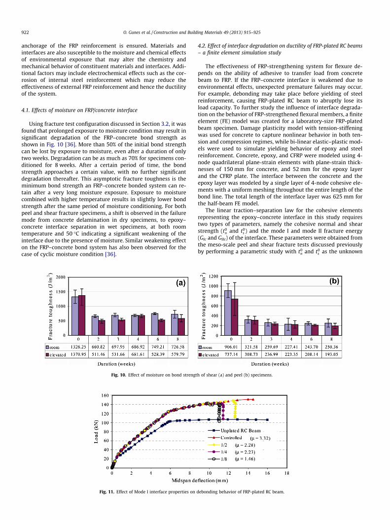
Using fracture test configuration discussed in Section 3.2, it wasfound that prolonged exposure to moisture condition may result insignificant degradation of the FRP–concrete bond strength asshown in Fig. 10 [36]. More than 50% of the initial bond strengthcan be lost by exposure to moisture, even after a duration of onlytwo weeks. Degradation can be as much as 70% for specimens con-ditioned for 8 weeks. After a certain period of time, the bondstrength approaches a certain value, with no further significantdegradation thereafter. This asymptotic fracture toughness is theminimum bond strength an FRP–concrete bonded system can re-tain after a very long moisture exposure. Exposure to moisturecombined with higher temperature results in slightly lower bondstrength after the same period of moisture conditioning. For bothpeel and shear fracture specimens, a shift is observed in the failuremode from concrete delamination in dry specimens, to epoxy–concrete interface separation in wet specimens, at both roomtemperature and 50 �C indicating a significant weakening of theinterface due to the presence of moisture. Similar weakening effecton the FRP–concrete bond system has also been observed for thecase of cyclic moisture condition [36].
Fig. 10. Effect of moisture on bond strengt
Fig. 11. Effect of Mode I interface properties on
4.2. Effect of interface degradation on ductility of FRP-plated RC beams– a finite element simulation study
The effectiveness of FRP-strengthening system for flexure de-pends on the ability of adhesive to transfer load from concretebeam to FRP. If the FRP–concrete interface is weakened due toenvironmental effects, unexpected premature failures may occur.For example, debonding may take place before yielding of steelreinforcement, causing FRP-plated RC beam to abruptly lose itsload capacity. To further study the influence of interface degrada-tion on the behavior of FRP-strengthened flexural members, a finiteelement (FE) model was created for a laboratory-size FRP-platedbeam specimen. Damage plasticity model with tension-stiffeningwas used for concrete to capture nonlinear behavior in both ten-sion and compression regimes, while bi-linear elastic–plastic mod-els were used to simulate yielding behavior of epoxy and steelreinforcement. Concrete, epoxy, and CFRP were modeled using 4-node quadrilateral plane-strain elements with plane-strain thick-nesses of 150 mm for concrete, and 52 mm for the epoxy layerand the CFRP plate. The interface between the concrete and theepoxy layer was modeled by a single layer of 4-node cohesive ele-ments with a uniform meshing throughout the entire length of thebond line. The total length of the interface layer was 625 mm forthe half-beam FE model.
The linear traction–separation law for the cohesive elementsrepresenting the epoxy–concrete interface in this study requirestwo types of parameters, namely the cohesive normal and shearstrength (t0
n and t0s ) and the mode I and mode II fracture energy
(GIc and GIIc) of the interface. These parameters were obtained fromthe meso-scale peel and shear fracture tests discussed previouslyby performing a parametric study with t0
n and t0s as the unknown
h of shear (a) and peel (b) specimens.
debonding behavior of FRP-plated RC beam.

O. Gunes et al. / Construction and Building Materials 49 (2013) 915–925 923
variables. For each moisture conditioning period, the values ofcohesive strength were varied until the maximum debonding loadwas obtained, while the corresponding values of GIc and GIIc wereobtained from the experiments. The values corresponding to drycase were t0
n = 6.1 MPa, t0s = 13.92 MPa, GIc = 900 N/m, and
GIIc = 1300 N/m. A series of parametric studies were then per-formed for the beam model by varying the values of t0
n, t0s , GIc
and GIIc. Reduction in the values of these parameters is equivalentto degradation of the concrete–epoxy interface due to environmen-tal exposure. Figs. 11 and 12 show load vs midspan deflection rela-tionships and corresponding ductility ratios when the properties ofthe interface in mode I or mode II were reduced to 1/2, 1/4, and 1/8of those for controlled dry case.
In dry condition, the FRP-plated RC beam has higher stiffnessthan its unplated counterpart, and ultimately fails by concrete cov-er delamination. However, when the interface is weakened, Figs. 11and 12 indicate that ductility of FRP-plated RC beams, as measuredby the ratio uu/uy, decreases as mode I or mode II interface prop-erties (i.e. cohesive strength and fracture energy) are reduced. Inmost cases, this reduction in ductility corresponds to interface sep-aration after yielding of the steel reinforcement. Once separationstarts, the beam significantly loses its capacity. In the case ofextensive degradation of the concrete/epoxy interface in mode II(i.e. when interface properties were reduced to 1/8), debondingof the FRP plate is predicted to take place even before yielding of
Fig. 12. Effect of mode II interface properties on
Fig. 13. Influence of debonding failures on t
steel reinforcement, rendering FRP-strengthening ineffective(Fig. 12).
5. Debonding failures under mechanical effects
Analysis and design of FRP–concrete systems are generally per-formed using the conventional approaches that assume perfectbonding between the FRP reinforcement and the concrete sub-strate. Violation of this assumption would mean loss of reinforce-ment for flexural members and ineffective confinement forcolumn elements, both of which would have negative impact onthe member ductility. Countless studies to date have encounteredpremature debonding failures especially in flexural members thatmay not only render the FRP strengthening ineffective, but alsomay harm the structure by reducing element ductility. Reviewsof experimental and modeling studies regarding debonding fail-ures can be found in [1] and [43]. Fig. 13 illustrates the significanceof debonding failures in terms of the ductility of beam elementsthrough experimental results obtained from ten beam tests [44].Each beam was strengthened using the same FRP flexural rein-forcement but varied in their shear capacity and anchorage condi-tions. The transverse load versus the FRP flexural reinforcementstrain at mid-span ðP � ef Þ was plotted for illustration. As can beseen from the figure, for the same steel and FRP flexural reinforce-
debonding behavior of FRP-plated RC beam.
he ductility of FRP strengthened beams.

Fig. 14. Damage evolution and debonding propagation at the epoxy–concrete interface.
924 O. Gunes et al. / Construction and Building Materials 49 (2013) 915–925
ment ratio, the ductility ratios of the beams vary between 1 and 2.7depending on the beam shear capacity and the anchorage condi-tions, the latter of which cannot be designed using the conven-tional ultimate strength design approaches.
Different debonding failure modes and associated ductility lev-els are also shown in Fig. 13 which illustrates the essential designissues in FRP strengthening of flexural members. Cover debondingwas the most brittle failure mode which took place at the steelreinforcement level and resulted in a ductility ratio of l = 1–1.2.Absence of anchorage and insufficient shear capacity were respon-sible for this brittle failure mode. When adequate shear capacitywas provided through additional internal transverse steel rein-forcement, the ductility ratio rose to l = 1.6–1.9 without any bondanchorage. In this case, the failure was at the epoxy–concreteinterface, within the concrete substrate. Fig. 14 shows the evolu-tion of debonding damage and propagation at the epoxy–concreteinterface [45,46]. Addition of transverse FRP reinforcement forbond anchorage along half and full length of the shear span re-sulted in ductility ratios of l = 2.2 and l = 2.7, respectively. Thiswide range of ductility behavior may have significant impact onthe behavior at the structural scale and requires advanced mechan-ics tools for modeling and design. A fracture energy based designapproach was proposed for bond anchorage design for flexuralFRP reinforcement to ensure ductile failure behavior of FRP-strengthened flexural members [43].
6. Knowledge gaps and further research needs
Throughout the paper, discussions on ductility of FRP–concretesystems at different scales were performed with the help of ductil-ity ratios as a quantitative measure of the system’s ability to un-dergo inelastic deformation before failure. Some importantobservations can be distilled from these discussions that provideguidance for identification of knowledge gaps and further researchneeds:
� FRP composite materials, due to their favorable mechanical anddurability characteristics have secured a permanent and grow-ing share in the construction market with current emphasis onstrengthening of RC members. Diverse applications of FRP com-posites on RC structures enjoy various degrees of success influ-enced by various material and strengthening parameters.� From ductility perspective, FRP and concrete materials with
ductility ratios approximately l � 1 and l � 2, respectively,do not form an ideal couple considering that higher ductilityratios are required at the structural level for satisfactory struc-tural performance. However, in reinforced concrete applica-tions, existence of reinforcing steel with superior ductilitycharacteristics may result in high system ductility ratio of theFRP–concrete structures. In that respect, more research isneeded for better understanding of the interactive systembehavior under various mechanical and environmental effects.
� Multi-scale investigations on the ductility of FRP–concrete sys-tems indicate a reduction in ductility at larger scales. Thisimportant observation emphasizes the need for more funda-mental research at smaller scales to better understand the duc-tility characteristics of FRP–concrete systems and to optimizematerial parameters at smaller scales to minimize the reductionin ductility at larger scales.� Understanding and modeling the influence of moisture, temper-
ature and other environmental exposure conditions on theintegrity and ductility of FRP–concrete systems is a priorityresearch area that also concerns the performance and safetyof existing FRP–concrete systems. More fundamental researchat smaller scales is necessary to properly characterize the cou-pled chemo-thermo-mechanical processes associated withenvironmental exposure conditions that adversely affect theintegrity, load and failure behavior as well as ductility of FRP–concrete systems in an effort to improve their overallperformance.
7. Conclusions
Multi-scale investigations on ductility characteristics of FRP–concrete systems are presented and discussed in this paper sharingthe insights gained into mechanics and durability of FRP concretesystems with emphasis on failure behavior and ductility. Knowl-edge gaps and further research needs are highlighted with empha-sis on the need for more fundamental research at smaller scales forbetter understanding and modeling of coupled mechanisms andprocesses as a basis for improved design strategies for better per-formance and ductility.
Acknowledgement
This research was supported by the National Science Founda-tion (NSF) through the grants CMS Grant Nos. 0010126, 0510797and 0856325 to Massachusetts Institute of Technology.
References
[1] Büyüköztürk O, Gunes O, Karaca E. Progress review on understandingdebonding problems in reinforced concrete and steel members strengthenedusing FRP composites. Constr Build Mater 2004;18:9–19.
[2] ACI-440. Guide for the design and construction of externally bonded FRPsystems for strengthening concrete structures, ACI 440.2R-02. FarmingtonHills (MI): American Concrete Institute; 2002.
[3] SEAOC. A brief guide to seismic design factors. Structure Magazine; 2009. p.30–2.
[4] FEMA. NEHRP recommended seismic provisions for new buildings and otherstructures: training and instructional materials. Washington (DC): FederalEmergency Management Administration; 2007.
[5] FEMA. NEHRP recommended seismic provisions for new buildings and otherstructures (FEMA P-750). Washington (DC): Federal Emergency ManagementAdministration; 2009.
[6] Aschheim M, Black EF. Yield point spectra for seismic design and rehabilitation.Earthquake Spectra 2000;16(2):317–35.

O. Gunes et al. / Construction and Building Materials 49 (2013) 915–925 925
[7] ATC. Seismic evaluation and retrofit of concrete buildings (ATC-40). California: Applied Technology Council; 1996.
[8] FEMA. Improvements of nonlinear static seismic analysis procedures (FEMA-440). Washington (DC): Federal Emergency Management Administration;2005.
[9] CEN. Eurocode 2: design of concrete structures – Part 1-1: General rules andrules for buildings, Ref. No. EN 1992-1-1:2004. E. Brussels: EuropeanCommittee for Standardization; 2004.
[10] Büyüköztürk O, Hearing B. Failure behavior of precracked concrete beamsretrofitted with FRP. J Compos Constr, ASCE 1998;2(3):138–44.
[11] Triantafillou TC, Plevris N. Strengthening of RC beams with epoxy-bondedfibre-composite materials. Mater Struct 1992;25:201–11.
[12] Lam L, Teng JG. Design-oriented stress–strain model for FRP-confinedconcrete. Constr Build Mater 2003;17:471–89.
[13] Maalej M, Tanwongsval S, Paramasivam P. Modeling of rectangular RCcolumns strengthened with FRP. Cem Concr Compos 2003;25:263–76.
[14] Gergely I, Pantelides CP, Nuismer RJ, Reaveley LD. Bridge pier retrofit usingfiber-reinforced plastic composites. J Compos Constr, ASCE 1998;2(4):165–74.
[15] Eurocode-8. Design of structures for earthquake resistance, Part 3:Strengthening and repair of buildings. European Standard, EN 1998-3, DocCEN/TC250/SC8/N343, Draft No. 32003.
[16] Di Ludovico M, Manfredi G, Mola E, Negro P, Prota A. Seismic behavior of a full-Scale RC structure retrofitted using GFRP laminates. J Struct Eng, ASCE2008;134(5):810–21.
[17] Di Ludovico M, Prota A, Manfredi G, Cosenza E. Seismic strengthening of anunder-designed RC structure with FRP. Earthquake Eng Struct Dyn2008;37:141–62.
[18] Au C, Büyüköztürk O. Effect of fiber orientation and ply mix on fiber reinforcedpolymer-confined concrete. J Compos Constr, ASCE 2005;9(5):397–407.
[19] Gunes, O. Failure modes in structural applications of fiber-reinforced polymer(FRP) composites and their prevention. In: Developments in fiber-reinforcedpolymer (FRP) composites for civil engineering. Uddin N, editor. Cambridge(UK): Woodhead Publishing; 2013.
[20] Colomb F, Tobbi H, Ferrier E, Hamelin P. Seismic retrofit of reinforced concreteshort columns by CFRP materials. Compos Struct 2008;82:475–87.
[21] Balsamo A, Colombo A, Manfredi G, Negro P, Prota A. Seismic behavior of a full-scale RC frame repaired using CFRP laminates. Eng Struct 2005;27:769–80.
[22] Pampanin S, Bolognini D, Pavese A. Performance-based seismic retrofitstrategy for existing reinforced concrete frame systems using fiber-reinforced polymer composites. J Compos Constr, ASCE 2007;11(2):211–26.
[23] Zou XK, Teng JG, De Lorenzis L, Xia SH. Optimal performance-based design ofFRP jackets for seismic retrofit of reinforced concrete frames. Composites: PartB 2007;38:584–97.
[24] Galal K, El-Sokkary H. Analytical evaluation of seismic performance of RCframes rehabilitated using FRP for increased ductility of members. J PerformConstr Facil 2008;22(5):276–88.
[25] Garcia R, Hajirasouliha I, Pilakoutas K. Seismic behavior of deficient RC framesstrengthened with CFRP composites. Eng Struct 2010;32:3075–85.
[26] Gunes O, Tumer R, Gunes B, Faraji S. Performance-based seismic retrofit designfor RC frames using FRP composite materials. To appear in Struct Eng Mech;2013, submitted for publication.
[27] Saatcioglu M, Razvi S. Strength and ductility of confined concrete. J Struct Eng,ASCE 1992;118(6):1590–607.
[28] Freeman SA. Review of the development of the capacity spectrum method.ISET J Earthquake Technol 2004;41(1):1–13.
[29] ATC. Evaluation and improvement of inelastic seismic analysis procedures(ATC-55). California: Applied Technology Council; 2001.
[30] Bank LC. Debonding of FRP plated concrete: a tri-layer fracture treatment.Composites for construction structural design with FRP materials. John Wileyand Sons, Inc.; 2006.
[31] Au C, Büyüköztürk O. Debonding of FRP plated concrete: a tri-layer fracturetreatment. Eng Fract Mech 2006;73(3):348–65.
[32] Laio A, Gervasio FL. Metadynamics: a method to simulate rare events andreconstruct the free energy in biophysics, chemistry and material science. RepProg Phys 2008;71(12):126601.
[33] Laio A, Parrinello M. Escaping free-energy minima. Prog Natl Acad Sci USA2002;99(20):12562.
[34] Lau D, Büyüköztürk O, Buehler MJ. Characterization of the intrinsic strengthbetween epoxy and silica using a multiscale approach. J Mater Res2012;27(14):1787–96.
[35] Lau D. Debonding in bi-layer material systems under moisture effects: amultiscale approach. Cambridge: Massachusetts Institute of Technology; 2012.
[36] Tuakta C, Büyüköztürk O. Deterioration of FRP/concrete bond system undervariable moisture conditions quantified by fracture mechanics. Compos Part B:Eng 2011;42:145–54.
[37] Lau D, Büyüköztürk O. Fracture characterization of concrete/epoxy interfaceaffected by moisture. Mech Mater 2010;42(12):1031.
[38] De Castro J, Keller T. Design of robust and ductile FRP structures incorporatingductile adhesive joints. Compos Part B: Eng 2010;41(2):148–56.
[39] Anyfantis KN. Finite element predictions of composite-to-metal bonded jointswith ductile adhesive materials. Compos Struct 2012;94(8):2632–9.
[40] Antonopoulos CP, T TC. Analysis of FRP-Strengthened RC beam-column joints. JCompos Constr, ASCE 2002;6(1):41–51.
[41] Bousselham A. State of research on seismic retrofit of RC beam-column jointswith externally bonded FRP. J Compos Constr, ASCE 2010;14(1):49–61.
[42] Polies W, Ghrib F, Sennah K. Rehabilitation of interior reinforced concrete slab-column connections using FRP sheets. Constr Build Mater 2010;24:1272–85.
[43] Gunes O, Büyüköztürk O, Karaca E. A fracture-based model for FRP debondingin strengthened beams. Eng Fract Mech 2009;76(12):1897–909.
[44] Gunes O. A fracture based approach to understanding debonding in FRPbonded structural members. Cambridge: MIT; 2004.
[45] Büyüköztürk O, Hearing B. Crack propagation in concrete compositesinfluenced by interface fracture parameters. Int J Solids Struct 1998;35(31–32):4055–66.
[46] Hearing B. Delamination in reinforced concrete retrofitted with fiberreinforced plastics. Cambridge: Massachusetts Institute of Technology; 2000.