dual steel frames with re-centering capacity and
TRANSCRIPT

COMPDYN 2017 6th ECCOMAS Thematic Conference on
Computational Methods in Structural Dynamics and Earthquake Engineering M. Papadrakakis, M. Fragiadakis (eds.)
Rhodes Island, Greece, 15–17 June 2017
DUAL STEEL FRAMES WITH RE-CENTERING CAPACITY AND REPLACEABLE STEEL SHEAR PANELS
C. Neagu1, F. Dinu1, and D. Dubina1
1 Politehnica University Timisoara, Department of Steel Structures and Structural Mechanics 1 Ioan Curea str., Timisoara 300224, Romania
e-mail: [email protected], [email protected], dan.dubina @upt.ro,
Keywords: Dual steel frames, re-centering capacity, replaceable thin-walled shear panels.
Abstract. Structures that have replaceable thin-walled steel shear panels are efficient struc-tural systems for resisting seismic loads owing to their high initial stiffness and reliable ener-gy dissipation capacity. In order to reduce the economic losses (loss of building operation, cost of repairing), the dissipative system may be designed to be easily removed and replaced if damaged by an earthquake. When the shear panels and moment resisting frames are used together (dual system), allowing the moment resisting frame to remain in elastic reduces the residual displacement after an earthquake and provides the re-centering capacity that is re-quired for removing and replacing the damaged walls.
The paper presents the concept of re-centering dual systems with thin-walled steel shear walls and link beams. The main steps of the design process are presented using case studies with application examples to buildings that have different configurations. The seismic performance is investigated using nonlinear static and/or dynamic analyses.

C. Neagu, F. Dinu and D. Dubina
1 INTRODUCTION
Conventional seismic design philosophy is based on dissipative response, which implicitly accepts damage of the structure under the design earthquake and leads to significant economic losses. Repair of the structure is often delayed by the residual displacement of the structure. In order to reduce the economic losses, the dissipative system may be designed to be easily re-moved and replaced if damaged by an earthquake. When the dissipative system and moment resisting frames are used together (dual system), allowing the moment resisting frame to re-main in elastic reduces the residual displacement after an earthquake and provides the re-centering capacity that is required for removing and replacing the damaged dissipative ele-ments [1].
The paper presents application of this concept to a dual structure, obtained by combining replaceable thin-walled steel shear panels with moment resisting frames (SPSW).
Steel frames with thin-walled shear panels have been previously studied and developed by Politehnica University Timisoara (UPT) [2] in the frame of several research projects.
2 SYSTEM DESCRIPTION
Most of the structures designed to modern codes would experience inelastic deformations even under moderate seismic action, with residual displacements after an earthquake. Repair is difficult in such cases. Solutions providing self-centering of the structure exist, but are technically demanding (post-tensioned strands, shape memory alloy devices, etc.). An alterna-tive solution is the system that provides re-centering capability, through removable dissipative members and dual (rigid-flexible) structural configuration.
One of this systems uses thin-walled steel shear panels. Typical SPSW systems include du-al systems with parallel moment frames (Figure 1a), coupled thin-walled shear panel system, whereby a coupling beam connects two shear panel bays (Figure 1b) and dual systems with link beams (Figure 1c). The SPSW dual system with link beams is a specific system, whereby a link beam connects two shear panel bays between two parallel moment frames. The panels are bordered by additional vertical boundary elements (stanchions, denoted as VBE) having simple connections at their ends to the beams (denoted as HBE).
(a) (b)
+ =
Basic moment frame Plate wall
Stanchion SPSW dual frame
(c)
Figure 1: SPSW frame systems: a) dual system with shear wall and moment resisting frames; b) dual system with shear wall and coupling beams; c) dual system with link beam.
Shear panels
Link beam

C. Neagu, F. Dinu and D. Dubina
The beam between the panels acts as a short, intermediate or long link, depending on the relative length of the shear panels and bay width. This systems has good seismic response, high dissipation capacity, and small residual drifts. Their use may also improve the overturn-ing stiffness and reduce the axial force demand on vertical boundary elements. The innovative application of such systems may be used for new constructions and also for upgrading the lat-eral resistance of existing constructions.
A challenge for the SPSW system is also the economic cost and construction efficiency. Connection between shear panels and bordering elements can be done using fillet welds but when bolted connections are used, the construction time may be reduced. Recent develop-ments in the field showed that steel panels, like other dissipative systems, may be designed and detailed to be replaced after an earthquake if the damage is limited in the panels but this requires special design and detailing conditions. If the more flexible MR frames are designed to remain elastic during the earthquake, they provide the restoring force that is necessary to re-center the structure and to allow the replacement of the damaged shear panels [1].
3 EXPERIMENTAL INVESTIGATION
A large experimental program has been carried out at Politehnica University in Timisoara, Romania [2], [3], on steel frames with thin-walled steel shear panels, in order to determine the monotonic and cyclic performance.
3.1 Experimental setup
The SPSW specimens have been extracted from a six story frame structure (Figure 2a). The two actuators used for the tests had 360mm stroke and 1000 kN capacity and 360 mm stroke and 500 kN capacity, respectively. Due to the stroke limitation, the specimens were half-scaled. The system had 2 shear panels per story of 2 mm thickness. The frames measured 3500 mm high and 4200 mm wide between member centerlines (Figure 2b). The slenderness ratio L/tw of shear walls amounted 595 for 2 mm panels, while the aspect ratio L/h was 0.8.
�
8.4m 4.8m 4.8m
6x3.5m
HEB 240 (VBE) HEB 240 (VBE)
HEA 180(HBE)
HEB 180 boundary stanchions
(a) (b)
Figure 2: SPSW: a) Six story frame structure; b) half-scale tested frame.
In order to evaluate the contribution of the boundary frames to the strength and stiffness of the structure, two types of beam-to-column connections were used. According to EN1993-1-8 classification [4], flush end plate connection was semi-rigid and weak partial strength (Mj,
Rd=0.4Mb,Rd) (further refereed as semi-rigid) and extended end plate connection aws rigid and strong partial strength, with a capacity almost equal to that of the connected beam (Mj,Rd = 0.9Mb,Rd) (further refereed as rigid) see Figure 3.
C. Neagu, F. Dinu and D. Dubina
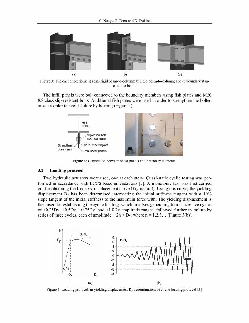
(a) (b) (c)
Figure 3: Typical connections: a) semi-rigid beam-to-column; b) rigid beam-to-column; and c) boundary stan-chion-to-beam.
The infill panels were bolt connected to the boundary members using fish plates and M20 8.8 class slip-resistant bolts. Additional fish plates were used in order to strengthen the bolted areas in order to avoid failure by bearing (Figure 4).
Figure 4: Connection between shear panels and boundary elements.
3.2 Loading protocol
Two hydraulic actuators were used, one at each story. Quasi-static cyclic testing was per-formed in accordance with ECCS Recommendations [5]. A monotonic test was first carried out for obtaining the force vs. displacement curve (Figure 5(a)). Using this curve, the yielding displacement Dy has been determined intersecting the initial stiffness tangent with a 10% slope tangent of the initial stiffness to the maximum force with. The yielding displacement is then used for establishing the cyclic loading, which involves generating four successive cycles of ±0.25Dy, ±0.5Dy, ±0.75Dy, and ±1.0Dy amplitude ranges, followed further to failure by series of three cycles, each of amplitude ± 2n × Dy, where n = 1,2,3… (Figure 5(b)).
(a) (b)
Figure 5: Loading protocol: a) yielding displacement Dy determination; b) cyclic loading protocol [5].
Dy D
Sj
Sj/10
D/Dy

C. Neagu, F. Dinu and D. Dubina
3.3 Results of cyclic testing
All specimens exhibited stable force-displacement behavior, with some pinching of hyste-resis loops that are in line with the characteristics commonly observed in other tests on SPSW. Plots of lateral load against top displacement of the three specimens tested under cyclic load-ing are shown in Figure 6.
�
-1400
-1000
-600
-200
200
600
1000
1400
-0.06 -0.04 -0.02 0 0.02 0.04 0.06
App
lied
load
, kN
Top displacement, %H
R-C-T2
1st cycle envelope
3rd cycle envelope
�
-1400
-1000
-600
-200
200
600
1000
1400
-0.06 -0.04 -0.02 0 0.02 0.04 0.06
App
lied
load
, kN
Top displacement, %H
SR-C-T2
1st cycle envelope
3rd cycle envelope
(a) (b)
Figure 6: Experimental frames hysteresis: a) specimen with rigid joints; b) specimen with semi-rigid joints.
The specimens, yielded at 0.65% and 0.7% top displacement, respectively. This indicates that until yielding, the rigidity of the beam-to-column joint has little effect on the behavior. Some local cracks were initiated at the panel corners at approximately 2% top displacement, which then propagated along the fillet weld of the plate to the additional fishplate. At the same top drift level, local plastic deformations were observed at the beam flange under com-pression for rigid connections (Figure 7(a)). The ultimate displacement of the specimens is approximately 4.5% top displacement, not owing to the specimen collapse but owing to the limitation of the actuator stroke. The contribution of the frame to overall response increases with lateral displacement. Thus, the difference between specimens with semi-rigid and rigid connections in terms of yield resistance and yield displacement was small, as mentioned be-fore, but ultimate capacity decreased by 20% when connections with low rigidity were used. As for the peak drift level, there was a small difference between the rigid and semi-rigid spec-imens.
(a) (b)
Figure 7: Specimen damages: a) Specimen after test; b) Plastic deformation in beam-to-column connections.

C. Neagu, F. Dinu and D. Dubina
4 CASE STUDY
4.1 Design of case study building frames
4.1.1. Description of examined building frames
The case study presented hereafter was based on the extraction of an exterior plane frame from four and eight story buildings, Figure 8. The frames consist of a rigid moment resisting frames (MRF) with three 8 m bays with two shear panels of 3 m as lateral system located in the interior bay (SPSW) (see chapter 2). The height of all buildings was considered 4 m.
gravityMRFBrace(Shear panel)
24.0
8.0 3.0 2.0 3.0 8.0
24.0
8.0
3.0
2.0
3.0
8.0
4.0
8.0 3.0 2.0 3.0 8.0
(a) (b)
Figure 8: Examined building frames: a) Configuration of the 3D buildings; b) Extracted exterior plane frame.
The gravity loads were applied as uniform distributed loads on the secondary beams and reduced to concentrated loads on the main frames. The dead load of 2.75 kN/m2 takes into account the self-weight of the concrete slab and steel sheeting. There were considered some superimposed loads from services, ceilings and raised floors of about 1 kN/m2. A 4.0 kN/m2 load was taken into account for perimeter walls. The 3.8 kN/m2 live load takes into account de destination of the buildings (offices - class B) and movable partition walls.
4.1.2. Preliminary assumptions
A number of analytical approaches are possible to achieve capacity design and determine the same forces acting on the boundary elements (HBE and VBE) including the shear panel thickness. One of these methods is the approximation of SPSW by a vertical truss with ten-sion diagonals only (further denoted as equivalent frame) (Figure 9), in line with AISC 2010 [7]. The area A of the equivalent braces is estimated in order to meet the structure’s drift re-quirements.
(a) (b)
Figure 9: Preliminary assumption: a) SPSW; b) Equivalent frame.

C. Neagu, F. Dinu and D. Dubina
4.1.3. Code-based design
The equivalent building frames were then designed according to EN1993-1 [8], EN1998 [6] and AISC 2010 [7].
Two different design cases were considered: moderate seismicity with medium class duc-tile building frames (DCM) and high seismicity with high class ductile building frames (DCH). Type 1-C spectrum (Figure 10a) was selected for design [6] considering two peak ground accelerations 0.3 for high seismicity case and 0.15 for moderate seismicity case, re-spectively (Figure 10b and c). Because no recommendation for reduction factor, q, is given in EN1998, a value of 5 was taken into consideration based on previews research [2],[3]. In case of moderate seismicity where medium ductility class structure is needed, a reduction factor of 3 was selected.
Columns, beams and stanchions were designed as steel members, with their section vary-ing depending on the floor and the building. The shear panels had lower steel grade (S235) than the rest of the structural members (S355). The beams production was not considered to be fully controlled, so that the properties of the beam material had to comply with EN1993-1-1 [8] recommendations with γov =1.25.
(a)
0.00
1.00
2.00
3.00
4.00
5.00
6.00
7.00
8.00
9.00
0 1 2 3 4
Se,
m/s
2
Period T, sec
High seismicity
Moderate seismicity
ag = 0.3
ag = 0.15
0.00
0.50
1.00
1.50
2.00
2.50
0 0.5 1 1.5 2 2.5 3 3.5 4
Sd,m
/s2
Period T, sec
High seismicity
Moderate seismicity
q= 5
q= 3
(b) (c)
Figure 10: Response spectra: a) Type 1 elastic response spectra [6]; b) Ground type C elastic spectra for high and moderate seismicity; c) Ground type C design spectra for high and moderate seismicity.
Accordance to AISC 2010 [7], the horizontal and vertical boundary element (HBE and VBE) are designed to resist the maximum forces developed under the tension field action of the fully yielded panels. Axial forces, shear forces, and bending moments develop in the SPSW boundary elements because of the overall overturning, shear, and tension field action in the panels. HBEs and VBEs should remain essentially elastic under forces generated by fully yielded panels, but flexural hinges are allowed at the ends of HBEs.
C

C. Neagu, F. Dinu and D. Dubina
Based on the area of the equivalent braces, A, obtained in design process, the thickness of the steel shear panels, tw, was obtained using the following equation, see [7]:
2 sin
sin 2s
wA
tL
(1)
θ is angle between the vertical and the longitudinal axis of the equivalent tension brace; L is the distance between VBE centerlines; α is the angle of inclination of the tension field in the shear panels, taken as 40°, see [7]; Ω is the system overstrength factor, as defined by FEMA 356 [9], and taken as 1.2 for
SPSW (Berman and Bruneau, 2003 [9] or NBCC 2015 [11]).
4.2 Seismic performance
In order to verify the plastic mechanism and re-centering capacity of the building frames, static non-linear analysis (push-over) was employed. The push-over analysis has taken into account an inverse triangular shape lateral load. As the re-centering capacity is of interest, the target displacement corresponding to ULS performance level was calculated, using N2 meth-od [12].
Beam and columns were modelled using beam elements having M3 and P-M3 hinge types placed at both ends. In order to model the shear panels, the so called "strip model" developed by Driver [13] was used. The shear panel is replaced by 10 inclined strips at angle α with re-spect to vertical, capable of transmitting tension forces only, and oriented in the same direc-tion as the principal tensile stresses in the panel. Figure 11a shows the strip model representation of a typical shear panel. The strips were modeled as double pinned beam ele-ments having a trilinear plastic axial P type hinge at the middle (Figure 11b and Table 1).
�
0
0.2
0.4
0.6
0.8
1
1.2
1.4
1.6
0 4 8 12 16 20 24 28 32
Nor
mal
ised
axi
al lo
ad
(P/P
y)
Normalised displacement (D/Dy)
A
B
C D
E
(a) (b)
Figure 11: Modelling of shear panels: a) Strip model; b) Tension only plastic hinge.
Hinge A B C D E P/Py Δ/Δy P/Py Δ/Δy P/Py Δ/Δy P/Py Δ/Δy P/Py Δ/Δy
Axial P 0 0 0.8 0 1.4 13 1.4 20 1.2 27
Table 1: Proposed strip tension only plastic hinge
By replacing the panel with these tension strips, the resulting steel structure can then be analyzed using currently available computer analysis software. This study was done using Sap2000 software [14].

C. Neagu, F. Dinu and D. Dubina
After running the PO analyses on elastic designed frames, for all 4 building frames, yield-ing was observed in MRF elements before the attainment of ultimate limit state. Therefor some of the sections were replaced in order to have re-centering capacity at ultimate limit state. Figure 12 and Figure 13 present the final sections for all 4 buildings.
(a) (b)
Figure 12: 4 story building frames: a) Moderate seismicity case; b) High seismicity case.
(a) (b)
Figure 13: 8 story building frames: a) Moderate seismicity case; b) High seismicity case.
Table 2 presents the target displacements and maximum inter-story drift ratios correspond-ing to ultimate limit state (blue dot in Figure 14) and the maxim displacement of re-centering capacity, dre-centering (red dot in Figure 14) with corresponding inter-story drift ratios, for all 4 building frames.
Figure 14 presents the capacity curves for all 4 build frames in terms of base shear force and top displacement. The frames designed assuming DCH, have a larger capacity and ductili-ty than the ones designed assuming DCM. The 8-story frames are more ductile than the 4-story frames and were designed to resist similar seismic forces (within the same ductility class).

C. Neagu, F. Dinu and D. Dubina
Frame Seismicity design case
ULS dre-centering
top displace-ment, m
inter-story drift ratio, %
max. dis-placement, m
inter-story drift ra-tio, %
4 high 0.209 1.6 0.217 1.7 moderate 0.117 0.9 0.216 1.8
8 high 0.310 1.3 0.334 1.4 moderate 0.156 0.6 0.339 1.5
Table 2: ULS target displacement, maximum re-centering displacement and corresponding inter-story drift ratios.
0
500
1000
1500
2000
2500
3000
3500
0 0.1 0.2 0.3 0.4 0.5 0.6 0.7 0.8 0.9 1
Bas
e sh
ear
forc
e, K
N
Top displacement, m
High seismicity
Moderate seismicity
ULS
Re-C
0.209
0.217
0.117
0.216
0
500
1000
1500
2000
2500
3000
3500
0 0.1 0.2 0.3 0.4 0.5 0.6 0.7 0.8 0.9 1 1.1 1.2 1.3 1.4 1.5
Bas
e sh
ear
forc
e, K
N
Top displacement, m
High seismicity
Moderate seismicity
ULS
Re-C
0.334
0.310
0.156
0.339
(a) (b)
Figure 14: Capacity curves: a) 4 story building frame; b) 8 story building frame.
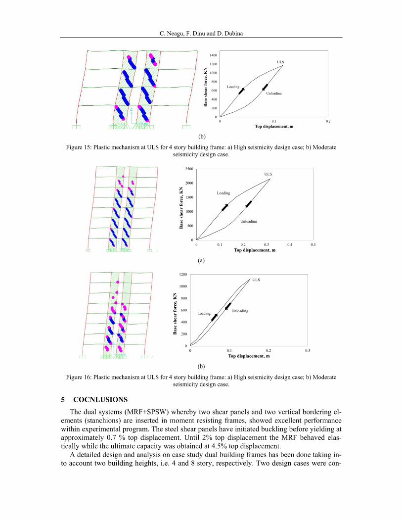
In order to evaluate the re-centering capacity of the frames, the plastic mechanisms are presented at target displacement corresponding to ULS (Figure 15 and Figure 16). Also, a re-centering analysis was performed, loading the frames till the target displacement correspond-ing to ULS and then unloading to 0 force. It can be seen that the plastic hinges are developed only in the shear panels with no damage in the MRF. Thus, the MRF has the necessary restor-ing force to re-center the building frames and then replace the damaged shear panels. This was also confirmed by the re-centering analysis done, which has showed that after unloading, no residual drift are present.
The objective of having no yielding in the MRFs before the attainment of ULS, represents the basic design requirement for dual frames with removable dissipative members.
0
500
1000
1500
2000
2500
0 0.1 0.2 0.3
Bas
e sh
ear
forc
e, K
N
Top displacement, m
Loading
Unloading
ULS
(a)
C. Neagu, F. Dinu and D. Dubina
0
200
400
600
800
1000
1200
1400
0 0.1 0.2
Bas
e sh
ear
forc
e, K
N
Top displacement, m
Loading
Unloading
ULS
(b)
Figure 15: Plastic mechanism at ULS for 4 story building frame: a) High seismicity design case; b) Moderate seismicity design case.
0
500
1000
1500
2000
2500
0 0.1 0.2 0.3 0.4 0.5
Bas
e sh
ear
forc
e, K
N
Top displacement, m
Loading
Unloading
ULS
(a)
0
200
400
600
800
1000
1200
0 0.1 0.2 0.3
Bas
e sh
ear
forc
e, K
N
Top displacement, m
LoadingUnloading
ULS
(b)
Figure 16: Plastic mechanism at ULS for 4 story building frame: a) High seismicity design case; b) Moderate seismicity design case.
5 COCNLUSIONS
The dual systems (MRF+SPSW) whereby two shear panels and two vertical bordering el-ements (stanchions) are inserted in moment resisting frames, showed excellent performance within experimental program. The steel shear panels have initiated buckling before yielding at approximately 0.7 % top displacement. Until 2% top displacement the MRF behaved elas-tically while the ultimate capacity was obtained at 4.5% top displacement.
A detailed design and analysis on case study dual building frames has been done taking in-to account two building heights, i.e. 4 and 8 story, respectively. Two design cases were con-

C. Neagu, F. Dinu and D. Dubina
sidered: moderate seismicity with medium ductility class structures (DCM) and high seismici-ty with high ductility class structures (DCH).
Nonlinear static analyses were employed in order to verify the collapse mechanism and re-centering capacity of building frames.
The study has showed that this innovative application of SPSW system enables for obtain-ing a “structural fuse” solution. The maximum inter-story drift ratios corresponding to ULS performance level, for all 4 building frames, amount less than 2% (e.g. 1.6% for 4 story and 1.3% for 8 story). When the SPSW frames are unloaded, they pass close to “0” displacement, with practically not residual displacement. Since the MRF are elastic up to ULS, the dual MRF+SPSW frames behave as a self-centering system.
Since, for the time being, this results have been obtained for particular structures, a larger parametric study would be necessary in order to confirm the generality of the solution. Also, for validation, a 3D structure test on a shacking table would be useful.
6 AKNOWLEDGEMENT
The INNOSEIS project received funding from the European Commission through the Re-search Fund for Coal and Steel (RFCS) under Grant Agreement Number 709434 with the par-ticipation of 11 partners. A large part of the information that is disseminated through the INNOSEIS project is also the result of various RFCS, EU and national research projects.
REFERENCES
[1] D. Dubina, A. Stratan, F. Dinu, Re-centering capacity of dual-steel frames. Steel Con-struction: Design and Research, 2(4), 73-81, 2011.
[2] D. Dubina, F. Dinu, Experimental evaluation of dual frame structures with thin-walled steel panels. Thin-Walled Structures, 78, 57-69, 2014.
[3] C. Neagu, Multi-storey building frames stiffened with dissipative shear wall. PHD The-sis, Ed. Politehnica, University Politehnica Timisoara, Romania, 2011.
[4] EN1993-1-8, Eurocode 3: Design of steel structures, Part 1-8: Design of joints. CEN, 2005.
[5] ECCS, Recommended Testing Procedures for Assessing the Behavior of Structural El-ements under Cyclic Loads. European Convention for Constructional Steelwork, Tech-nical Committee 1, TWG 1.3 – Seismic Design, No.45, 1985.
[6] EN 1998-1, Eurocode 8: Design of structures for earthquake resistance - Part 1: Gen-eral rules, seismic actions and rules for building. CEN, 2004.
[7] ANSI/AISC 341-10, Seismic provisions for structural steel buildings. American Insti-tute for Steel Construction, 2010.
[8] EN 1993-1-1, Eurocode 3: Design of steel structures - Part 1-1: General rules and rules for buildings. CEN, 2005.
[9] J. W. Berman, M. Bruneau, Plastic Analysis and Design of Steel Plate Shear Walls. Journal of Structural Engineering, 129(11), 448-1456, 2003.
[10] FEMA 356, Prestandard and commentary for the seismic rehabilitation of buildings. Federal Emergency Management Agency and American Society of Civil Engineers. Washington DC, USA, 2000.

C. Neagu, F. Dinu and D. Dubina
[11] NBCC, National Building Code of Canada. Institute for Research in Construction, Na-tional Research Council of Canada, Ottawa, 2015.
[12] P. Fajfar, A nonlinear analysis method for performance-based seismic design. Earth-quake Spectra, 16(3), 573-92, 2000.
[13] R.G. Driver, G.L. Kulak, D.J.L Kennedy, A.E. Elwi, Cyclic Test of a Four-Storey Steel Plate Shear Wall. ASCE Journal of Structural Engineering, 124(2), 112-120, 1998.
[14] CSI, SAP2000 - Three Dimensional Static and Dynamic Finite Element Analyses of the Structures. Computers and Structures Inc., Berkeley, CA, 2000.