dual image grooved sign final
TRANSCRIPT
1
Dual Image Grooved Sign (DIGS)
Keaton Aktay Undergraduate Student
Jin young Kim Graduate Student
Timothy D. Ropp Faculty Advisor
April 2012

2
COVER PAGE
Title of Design: Dual Image Grooved Sign
Design Challenge addressed: Runway Safety/Runway Incursions/Runway Excursions
University name: Purdue University
Team Member(s) names: Keaton Aktay, Jin Young Kim________________________
Number of Undergraduates: 1
Number of Graduates: 1
Advisor(s) name: Professor Timothy Ropp
3
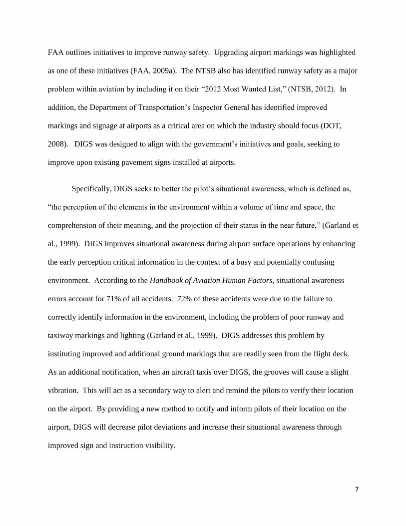
1. EXECUTIVE SUMMARY
This design packet addresses the Runway Safety Challenge of the FAA Design
Competition for Universities in the 2011-2012 academic year. Our team’s thorough research,
review of current airport surface signage systems, and interaction with industry professionals
contributed to our design solution for runway safety. The design is titled Dual Image Grooved
Sign (DIGS). DIGS, embedded into the pavement, is designed to display two information signs
when viewed from different angles, extending the system’s use in two directions in relatively the
same amount of area that a runway or taxiway pavement sign would occupy. As designed, in
ground DIGS pavement signs will be placed in taxiways, providing the same ground guidance
information such as TERM or taxiway J. A pair of DIGS will be placed on a taxiway, one on
each side of the centerline, increasing the pilot’s ability to determine his or her location on the
airport. This will increase pilot awareness on the airside, reducing runway incursions.
Ultimately, runway safety improvement will produce cost savings throughout the aviation
industry and save lives.
4
Table of Contents
1. EXECUTIVE SUMMARY................................................................................................................. 3
2. PROBLEM STATEMENT AND BACKGROUND ........................................................................ 6
3. LITERATURE REVIEW................................................................................................................... 8
3.1. Lenticular printing ...................................................................................................................... 8
3.2. MITRE 3-D painting ................................................................................................................... 9
3.3. Advisory Circulars ...................................................................................................................... 9
4. PROBLEM SOLVING APPROACH ............................................................................................. 10
4.1. Design Overview ........................................................................................................................ 10
4.2. Design Specification .................................................................................................................. 12
4.3. Installation ................................................................................................................................. 15
4.4. Optional Features ...................................................................................................................... 16
4.5. Operational Considerations ..................................................................................................... 17
4.5.1. Vertical Viewing Angle ..................................................................................................... 18
4.5.2. Lateral Viewing Angle ...................................................................................................... 20
4.5.3. Wheel Drop (Vibration) .................................................................................................... 21
5. SAFETY RISK ASSESSMENT ....................................................................................................... 23
5.1. Obstructions .............................................................................................................................. 23
5.2. Propeller Strike ......................................................................................................................... 24
5.3. Pilot Error .................................................................................................................................. 25
5.4. Structural Damage .................................................................................................................... 26
6. INDUSTRY INTERACTION .......................................................................................................... 26
6.1. John Haddock and Jason Weiss .............................................................................................. 27
6.2. Stewart Schreckengast .............................................................................................................. 28
6.3. Michael Suckow ........................................................................................................................ 29
6.4. Betty Stansbury ......................................................................................................................... 30
7. PROJECT IMPACT ......................................................................................................................... 30
7.1. DIGS Costs ................................................................................................................................ 31
7.2. Cost Benefit from DIGS ........................................................................................................... 33
7.3. Airport Example ....................................................................................................................... 34
Appendix A ................................................................................................................................................. 36

5
Appendix B ................................................................................................................................................. 37
Appendix C ................................................................................................................................................. 38
Appendix D ................................................................................................................................................. 39
Appendix E ................................................................................................................................................. 40
Appendix F.................................................................................................................................................. 44
Appendix G- DIY DIGS ............................................................................................................................. 48

6
2. PROBLEM STATEMENT AND BACKGROUND
A recurring and prevalent problem within the aviation industry has been runway safety.
With 954 runway incursions occurring in 2011, it is an issue that cannot be thrown to the way
side (FAA, 2012c). While 2011 showed a slight improvement from 2010 (955 incursions),
consequences of even one mistake in aviation can be unacceptably high (FAA, 2011b). Runway
safety incidents costing approximately $100 million annually in the United States, and at their
lowest consequence result in a ripple effect of delays at airports. Runway safety needs to be
addressed, and the number of incursions needs to drop (Honeywell, 2009) if we are to maintain
safety amidst growing demand for air travel.
Many innovative ideas have been developed and implemented to improve runway safety.
However, obstacles are still in the way for a nationwide roll-out and implementation. One such
idea is runway status lights (RWSL). RWSL is a novel and dynamic system to improve runway
safety, by alerting pilots when a runway is in use. However, it has been sparsely installed due to
high cost, with the most recent figures found for the installation of RWSL totaling $7.7 million at
Los Angeles International Airport (Adams, 2008).
The Dual Image Grooved Sign (DIGS) design is believed to offer a quick, feasible and
affordable solution to help combat the risks of runway incursions. It provides advantages to
industry and addresses the recurring runway safety issues grappled with by industry for years.
The FAA has outlined the problematic areas of runway safety in various reports: the
National Runway Safety Plan (NSRP) 2012-2014 and the FAA’s Runway Safety Call to Action.
In the NSRP, the FAA determined the most frequent runway incursion is attributed to Pilot
Deviations, accounting for 65% of all incursions (FAA, 2011b). Within the Call to Action, the
7
FAA outlines initiatives to improve runway safety. Upgrading airport markings was highlighted
as one of these initiatives (FAA, 2009a). The NTSB also has identified runway safety as a major
problem within aviation by including it on their “2012 Most Wanted List,” (NTSB, 2012). In
addition, the Department of Transportation’s Inspector General has identified improved
markings and signage at airports as a critical area on which the industry should focus (DOT,
2008). DIGS was designed to align with the government’s initiatives and goals, seeking to
improve upon existing pavement signs installed at airports.
Specifically, DIGS seeks to better the pilot’s situational awareness, which is defined as,
“the perception of the elements in the environment within a volume of time and space, the
comprehension of their meaning, and the projection of their status in the near future,” (Garland et
al., 1999). DIGS improves situational awareness during airport surface operations by enhancing
the early perception critical information in the context of a busy and potentially confusing
environment. According to the Handbook of Aviation Human Factors, situational awareness
errors account for 71% of all accidents. 72% of these accidents were due to the failure to
correctly identify information in the environment, including the problem of poor runway and
taxiway markings and lighting (Garland et al., 1999). DIGS addresses this problem by
instituting improved and additional ground markings that are readily seen from the flight deck.
As an additional notification, when an aircraft taxis over DIGS, the grooves will cause a slight
vibration. This will act as a secondary way to alert and remind the pilots to verify their location
on the airport. By providing a new method to notify and inform pilots of their location on the
airport, DIGS will decrease pilot deviations and increase their situational awareness through
improved sign and instruction visibility.

8
3. LITERATURE REVIEW
3.1.Lenticular printing
Lenticular printing is a technology used to give the illusion of depth and morphing effect
to 2D image. This technology was one of considered for use in our DIGS design. The technology
can also display different information when viewed from different vertical viewing angle. Unlike
DIGS, lenticular printing must be made of a sheet of transparent material, which is overlaid on
the lenticular image. The transparent surface is made of a cylinder shaped lenticular lenses that
reflects the image, and displays different image depending on the viewer’s eye position. (Weiss
& Pilossf, 2004)
Compared to the DIGS concept, lenticular printing does not have lateral viewing limits.
However, while this capability may be desirable in other venues, it is not a suitable technology
for the airport environment. Structurally, the amount of duress caused by the weight of an
aircraft that the lenticular style lenses would have to withstand without damage has not been
determined. For most applications, a transparent plastic is used to create the lenticular lenses.
Conventional plastics cannot withstand heavy weight and high temperature conditions associated
with an active airport environment when compared with concrete. Even if an alternative to
transparent material were used, there is the risk that it may be scratched and rubber build-up may
occur, obstructing the image. Furthermore, transparent materials may cause reflective glare,
inhibiting and reducing the technology’s usefulness during daytime hours. With those limitations
and design considerations as a baseline, our team elected to focus on proven, pre-existing
materials and to innovate literally “on top” of them.
9
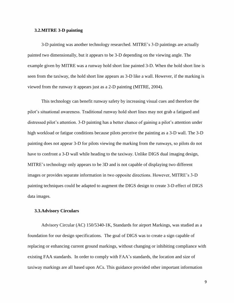
3.2.MITRE 3-D painting
3-D painting was another technology researched. MITRE’s 3-D paintings are actually
painted two dimensionally, but it appears to be 3-D depending on the viewing angle. The
example given by MITRE was a runway hold short line painted 3-D. When the hold short line is
seen from the taxiway, the hold short line appears as 3-D like a wall. However, if the marking is
viewed from the runway it appears just as a 2-D painting (MITRE, 2004).
This technology can benefit runway safety by increasing visual cues and therefore the
pilot’s situational awareness. Traditional runway hold short lines may not grab a fatigued and
distressed pilot’s attention. 3-D painting has a better chance of gaining a pilot’s attention under
high workload or fatigue conditions because pilots perceive the painting as a 3-D wall. The 3-D
painting does not appear 3-D for pilots viewing the marking from the runways, so pilots do not
have to confront a 3-D wall while heading to the taxiway. Unlike DIGS dual imaging design,
MITRE’s technology only appears to be 3D and is not capable of displaying two different
images or provides separate information in two opposite directions. However, MITRE’s 3-D
painting techniques could be adapted to augment the DIGS design to create 3-D effect of DIGS
data images.
3.3.Advisory Circulars
Advisory Circular (AC) 150/5340-1K, Standards for airport Markings, was studied as a
foundation for our design specifications. The goal of DIGS was to create a sign capable of
replacing or enhancing current ground markings, without changing or inhibiting compliance with
existing FAA standards. In order to comply with FAA’s standards, the location and size of
taxiway markings are all based upon ACs. This guidance provided other important information

10
and context such as paint and additional airport marking requirements and FAA’s goals in this
area (FAA, 2010b).
AC 150/5370-17, airside use of heated pavement was reviewed for pavement heating
standards and current technologies. This particular AC helped the team’s design approach for
taking pavement heating technologies into consideration to meet heated pavement standards
(FAA, 2011a).
4. PROBLEM SOLVING APPROACH
4.1.Design Overview
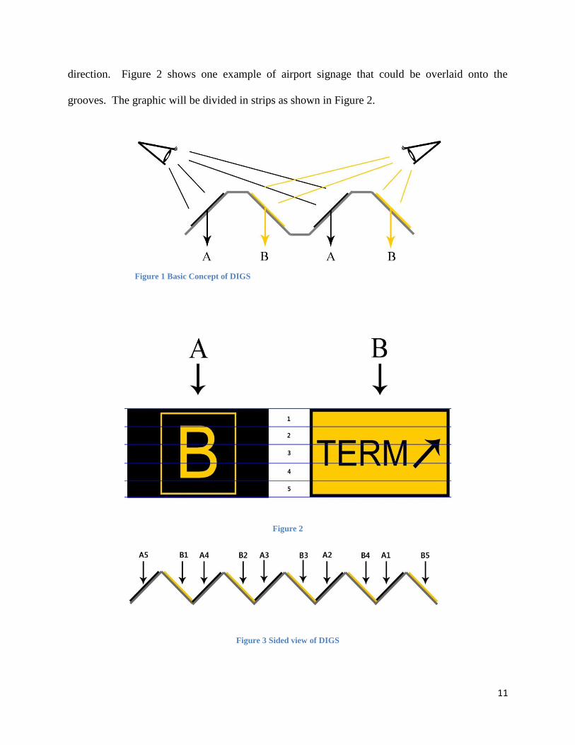
The Dual Image Grooved Sign (DIGS) design consists of an embedded, grooved concrete
surface sign that displays two images when viewed from different angles (Figure 1). This dual
surface signage is achieved by grinding and grooving a defined section of the concrete surface,
then overlaying the surface with differing airport markings on either side of the grooves. The
grooves will be in successive rows on the surface and angled, ideally at 45 degrees but could be
changed to achieve best viewing angle. The grooves are angled to enable image visualization
from a distance. The grooves will be triangular with a flat edge in between each groove. The
tops of the grooves will also be flattened as opposed to converging to a point, increasing the
structural resistance, to wear and tear from vehicle traffic. The groove design can be seen in
Figure 1.
On each of the A sides of the grooves, a graphic will be placed, displaying the desired
information. The same concept is applied to the B sides of the grooves, but with different
information. This design allows for dual use information display depending on the approach
11
direction. Figure 2 shows one example of airport signage that could be overlaid onto the
grooves. The graphic will be divided in strips as shown in Figure 2.
Figure 2
Figure 3 Sided view of DIGS
Figure 1 Basic Concept of DIGS

12
Figure 4 Aerial view of DIGS
The corresponding strip number is placed in order on a side of a groove as seen in Figure
3. This will achieve a congruent picture of the graphic when viewed from an elevated position.
Figure 4 depicts the sign if it was viewed from above.
DIGS will be used to enhance pre-existing taxiway
signs such as taxiway location signs, direction signs, and
geographic position markings. DIGS will show different
markings to two opposite directions. Airport operators can
choose which information is given to what position, unlike
traditional markings displaying same information when
viewed from all sides.
4.2.Design Specification
Groove Design
Each groove for DIGS has an angle of 45 degrees.
Figure 5 Angle demonstration
13
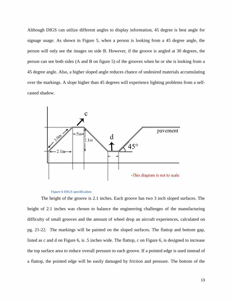
Although DIGS can utilize different angles to display information, 45 degree is best angle for
signage usage. As shown in Figure 5, when a person is looking from a 45 degree angle, the
person will only see the images on side B. However, if the groove is angled at 30 degrees, the
person can see both sides (A and B on figure 5) of the grooves when he or she is looking from a
45 degree angle. Also, a higher sloped angle reduces chance of undesired materials accumulating
over the markings. A slope higher than 45 degrees will experience lighting problems from a self-
casted shadow.
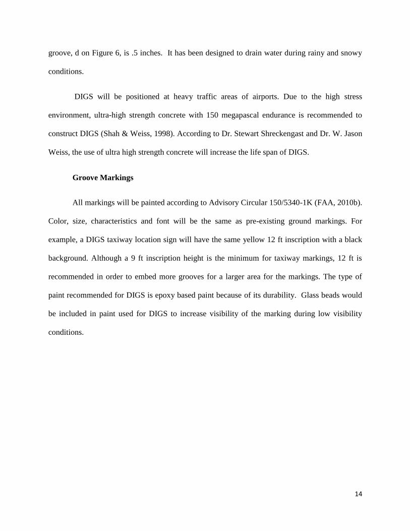
The height of the groove is 2.1 inches. Each groove has two 3 inch sloped surfaces. The
height of 2.1 inches was chosen to balance the engineering challenges of the manufacturing
difficulty of small grooves and the amount of wheel drop an aircraft experiences, calculated on
pg. 21-22. The markings will be painted on the sloped surfaces. The flattop and bottom gap,
listed as c and d on Figure 6, is .5 inches wide. The flattop, c on Figure 6, is designed to increase
the top surface area to reduce overall pressure to each groove. If a pointed edge is used instead of
a flattop, the pointed edge will be easily damaged by friction and pressure. The bottom of the
Figure 6 DIGS specification
14
groove, d on Figure 6, is .5 inches. It has been designed to drain water during rainy and snowy
conditions.
DIGS will be positioned at heavy traffic areas of airports. Due to the high stress
environment, ultra-high strength concrete with 150 megapascal endurance is recommended to
construct DIGS (Shah & Weiss, 1998). According to Dr. Stewart Shreckengast and Dr. W. Jason
Weiss, the use of ultra high strength concrete will increase the life span of DIGS.
Groove Markings
All markings will be painted according to Advisory Circular 150/5340-1K (FAA, 2010b).
Color, size, characteristics and font will be the same as pre-existing ground markings. For
example, a DIGS taxiway location sign will have the same yellow 12 ft inscription with a black
background. Although a 9 ft inscription height is the minimum for taxiway markings, 12 ft is
recommended in order to embed more grooves for a larger area for the markings. The type of
paint recommended for DIGS is epoxy based paint because of its durability. Glass beads would
be included in paint used for DIGS to increase visibility of the marking during low visibility
conditions.

15
4.3.Installation
Figure 7 DIGS Installation
To comply with current FAA advisory circulars, DIGS will be installed 3 ft away from
the taxiway centerline. To install the DIGS, part of the taxiway pavement will be cut into squares
or rectangular shapes. The size of cutout will be different for the type and required size of the
taxiway sign. A DIGS will consist of four square modules, each 7.4 x 7.4 ft and constructed
from ultra-high strength concrete with 17 grooves as specified on pg. 13. For example, to install
a taxiway location sign, a 14.8 x 14.8 ft square of pavement is required to be removed to install
four DIGS modules as shown in Figure 7. For taxiway direction signs with arrows or surface
painted holding position signs on taxiways, additional DIGS modules are required to match the
specified size, and the pavement needs to be cut to match the size of the modules. Our prototype,
Figure 9 on pg. 18, provides a realistic example of what a DIGS module would look like. Gaps
between the DIGS modules and the pavement surface (red line shown on figure 7) would be
16
filled with a joint sealant similar to the sealants installed between concrete joints at airports
today. This would help reduce any drainage issues and vibration damages from vehicle traffic.
The modular installation method was selected to reduce overall time required for
installations. Unlike grooving surface with a machine, the modules can be mass produced to
decrease the manufacturing cost, and ensure uniform quality of each module. If DIGS instead
used pre-existing pavement, which would be grooved to meet the DIGS design, there would not
be uniform quality throughout the piece of pavement. Additionally it was determined that if one
groove were to spall or become damaged, the entire DIGS unit might need to be replaced. By
using four modules, only one part of DIGS would require replacement if damaged, therefore
reducing maintenance costs.
To prevent water and snow accumulation, the DIGS unit would need to be crested to
allow for drainage. To help facilitate the drainage, water drain grooves would need to be
installed in addition to DIGS. If pre-existing taxiway grooves are as deep as 2.1 inches,
additional water drain would not be required. To install the water drains, a traditional pavement
cutter or grooving machine would be used. In the DIGS design, a water collection groove is
embedded on the nearest side to the edge of the taxiway to collect water from each groove. The
water would then flow to groove drains. Each water drain groove would be required to have a
depth of 2.1 inches and be connected between the DIGS modules and sides of the taxiway shown
as blue lines on figure 7.
4.4. Optional Features
DIGS is designed to endure all weather conditions. For airports that experience severe
snow during winter, heated pavement would be required for DIGS. Due to the incorporation of
17
grooves in DIGS’ design, the grooves could be heavily damaged by snow plows. Furthermore,
snow removal brushes and brooms can only be used when snow depth is below 0.5 inches,
making the use of this evolution of the DIGS design potentially unsuitable in areas with heavy
snowfall. Heated pavement would solve this problem by melting snow that accumulates between
each groove, then draining to sides of the pavement. To reduce installation difficulty and heating
source problems, the electronic heating method is recommended instead of the hydronic heating
method. A grid of insulated conducting mesh would be recommended to be installed under each
DIGS module to provide heat. It is also highly recommended to install a heating cable under the
water drain grooves.
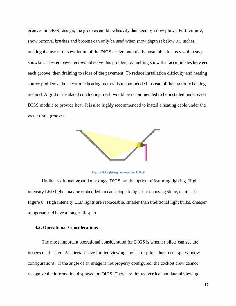
Figure 8 Lighting concept for DIGS
Unlike traditional ground markings, DIGS has the option of featuring lighting. High
intensity LED lights may be embedded on each slope to light the opposing slope, depicted in
Figure 8. High intensity LED lights are replaceable, smaller than traditional light bulbs, cheaper
to operate and have a longer lifespan.
4.5. Operational Considerations
The most important operational consideration for DIGS is whether pilots can see the
images on the sign. All aircraft have limited viewing angles for pilots due to cockpit window
configurations. If the angle of an image is not properly configured, the cockpit crew cannot
recognize the information displayed on DIGS. There are limited vertical and lateral viewing

18
angles for DIGS. Further evaluation on the effects of vibration when aircraft taxi over the
grooves at various speeds would be included in further development of the DIGS concept.
4.5.1. Vertical Viewing Angle
The vertical viewing angle is affected by the angle of groove. As mentioned on the
groove design on pg. 13, using a low grooved angle would limit the visibility from steep angles.
Although there is no limitation for the lower angles, research and experimentation on prototypes
revealed that images can potentially be difficult to recognize at certain angle distances. A DIGS
design with a higher number of smaller grooves on the same area (similar to resolution on a
video screen) can display a better image for lower vertical viewing angle due to less 'pixelation'
or distortion of the image. However, due to time and prototype manufacturing limitations for this
design study, the current number and size of grooves are limited, as listed on pg. 13. To test
vertical viewing angle, we made a smaller prototype of the DIGS, shown in Figures 9, 10, and
11. It should be noted that the prototype shown in these figures is smaller and does not match
proposed design dimensions but was initially developed for experimenting with visualization.
For the actual product envisioned, more grooves will be used to display the same image,
decreasing image distortion and improving image clarity compared to the prototype.
Figure 9 Viewing angle 45˚ Figure 10 Viewing angle 30˚ Figure 11 Viewing angle 15˚

19
As depicted in Figures 8 to 10, DIGS can be recognized from different angles from 45
degrees to a shallow 15 degree downward viewing angle. The prototype was still recognizable
even from 10 degrees. According to Boeing's ground maneuvering manual (Boeing, 2011a, b, &
c), Boeing 737-800,747-400 and 777-200 each have viewing downward angles of 15, 18.5, and
21 degrees, respectively. These viewing angles are shown in Figure 12. Pilots of all modern
Boeing aircraft can locate and identify DIGS from the cockpit. The viewing angle of each
airplane can be different depending on the pilot's seating height. Boeing uses a designed eye
reference point to determine the viewing angle, but some pilots do not adjust their chairs
according to the eye reference point. Further research is recommended to determine pilots’
seating habits and how it will affect the performance of DIGS.
Figure 12 Boeing 737 Vertical Visual Angle
20
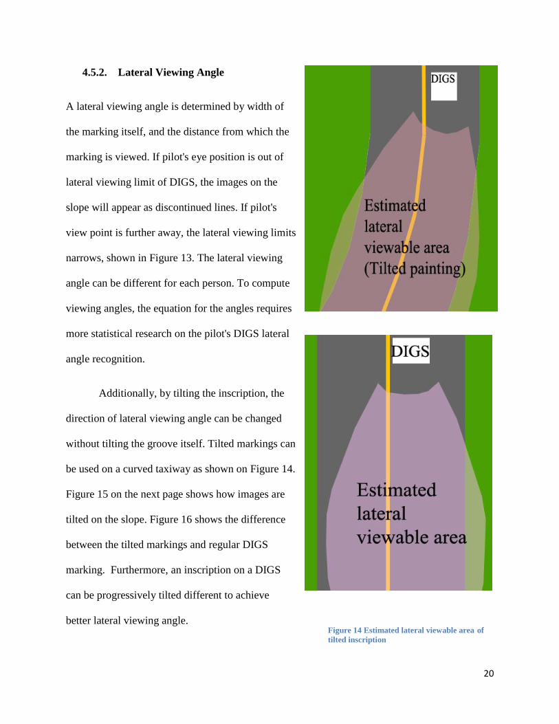
Figure 14 Estimated lateral viewable area of
tilted inscription
Figure 13 Estimated lateral viewable area
4.5.2. Lateral Viewing Angle
A lateral viewing angle is determined by width of
the marking itself, and the distance from which the
marking is viewed. If pilot's eye position is out of
lateral viewing limit of DIGS, the images on the
slope will appear as discontinued lines. If pilot's
view point is further away, the lateral viewing limits
narrows, shown in Figure 13. The lateral viewing
angle can be different for each person. To compute
viewing angles, the equation for the angles requires
more statistical research on the pilot's DIGS lateral
angle recognition.
Additionally, by tilting the inscription, the
direction of lateral viewing angle can be changed
without tilting the groove itself. Tilted markings can
be used on a curved taxiway as shown on Figure 14.
Figure 15 on the next page shows how images are
tilted on the slope. Figure 16 shows the difference
between the tilted markings and regular DIGS
marking. Furthermore, an inscription on a DIGS
can be progressively tilted different to achieve
better lateral viewing angle.

21
Figure 15 Tilted inscription Figure 16 Inscription comparison
4.5.3. Wheel Drop (Vibration)
As aircraft tires move from the peak of the groove toward the bottom of the groove, the
aircraft will experience a wheel drop. Continuous wheel drop and lift from the grooves will cause
a vibration. While the duration of this vibration would be minimal, further evaluation would be
required to assess potential cumulative wear to aircraft structure for both large and smaller
General Aviation (GA) aircraft. Additional study of potential increase, decrease or zero effect on
propeller strikes would also be required. To minimize the degree of vibration, the groove size
could be reduced with additional design consideration given to the manufacturing process and
groove endurance.
To calculate amount of wheel drop, we measured tire radius of a 5.00-5 size general
aviation tire and retrieved dimension listings for a Boeing 737-800 tire radius from Boeing's
website. B737-800's tire radius is 13.5 inches, and the radius of a Cessna 172’s 5.00-5 tires is 7

22
inches (Boeing, 2011a, p. 436). We used Equation 1 to calculate the amount of wheel drop that
occurs with the groove specifications listed on pg. 13. Refer to Figure 17 for a graphical
representation of the wheeldrop. Our calculation does not consider the deflation of the tire
pressure.
Equation 1
Wheel Drop = Tire radius - Cos (Sin-1
(half the distance between the peaks/ tire radius))
5-500 tire wheel drop= 7 inches - Cos (Sin-1
(2.35inches/7inches)=0.4inches
Boeing 737-800 wheel drop = 13.5 inches - Cos (Sin-1
(2.35inches/13.5inches)=0.2inches
Figure 17 Wheel drop calculation
For a B737-800, the wheel drop is 0.2 inches. This wheel drop is not significant enough
to cause damage to the airframe, but it may lead to slight passenger discomfort at a high speed.
For GA aircraft using 5.00-5 tires, the wheel drop was 0.4 inches. Again, while this wheel drop
23
may not be considered big, there is still the possibility for a propeller strike if the aircraft is
taxiing at an excessively high speed. Overall, there are some safety concerns with GA aircraft,
but the groove size allows for safe taxi when GA pilots operate at low speeds. If ultra-high
strength concrete technology can create even smaller groove sizes, our specifications will be
changed to reduce wheel drop and vibration.
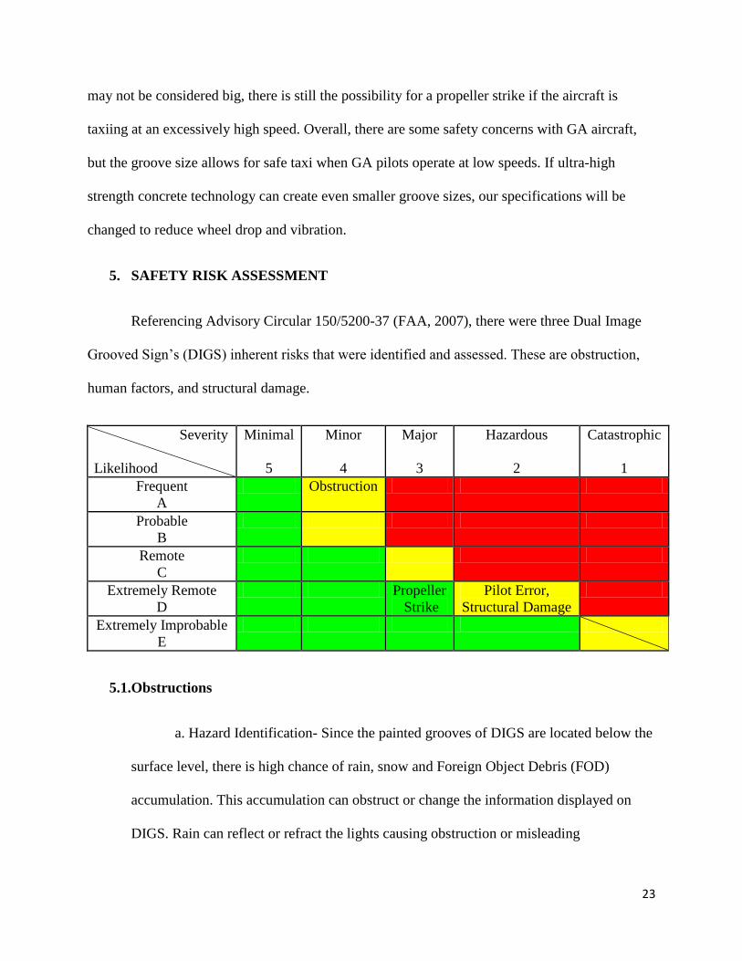
5. SAFETY RISK ASSESSMENT
Referencing Advisory Circular 150/5200-37 (FAA, 2007), there were three Dual Image
Grooved Sign’s (DIGS) inherent risks that were identified and assessed. These are obstruction,
human factors, and structural damage.
Severity
Likelihood
Minimal
5
Minor
4
Major
3
Hazardous
2
Catastrophic
1
Frequent
A
Obstruction
Probable
B
Remote
C
Extremely Remote
D
Propeller
Strike
Pilot Error,
Structural Damage
Extremely Improbable
E
5.1.Obstructions
a. Hazard Identification- Since the painted grooves of DIGS are located below the
surface level, there is high chance of rain, snow and Foreign Object Debris (FOD)
accumulation. This accumulation can obstruct or change the information displayed on
DIGS. Rain can reflect or refract the lights causing obstruction or misleading
24
information. Snow can accumulate between the grooves blocking the markings. Lastly,
FOD located between the grooves not only can obstruct the markings but can also cause
damage to nearby moving aircraft.
b. Risk Assessment- Obstructions by rain, snow and FOD can occur often.
Misleading information caused by these obstructions can lead to hazardous pilot
confusion. Additionally, the FOD that is produced from DIGS can damage aircraft.
Appropriate measures to monitor and inspect DIGS would need to be taken by airport
operations staff.
c. Risk Treatment- As mentioned in the problem solving approach, the DIGS
design includes cresting the pavement and installing water drains to remove any chance
of rain accumulation. As with FOD, airports would be recommended to ensure the proper
function of the drainage system of DIGS frequently in heavy rain and snow seasons. To
prevent snow accumulation, airport managers can choose to install heated pavement
below DIGS as described on pg. 16-17.
5.2.Propeller Strike
a. Hazard Identification- As mentioned on pg. 22, GA aircraft with 5-5.00 inch
tires will have .4 inches of total wheel drop when the aircraft is traversing over DIGS.
Although .4 inches of wheel drop is not significant enough to directly cause the prop
strike, excessively high speed taxi can cause loss of control over DIGS. The vibration
from high speed taxiing over the grooves can cause a resonance cascade of suspension
leading to loss of balance of GA aircraft.
25
b. Risk Assessment- It is extremely remote to have a propeller strike of GA
aircraft. Each GA aircraft has a larger propeller clearance than the actual wheel drop that
is experienced when crossing the grooves. Also, most pilots taxi within safe speed limits,
and it is very unlikely to find pilots taxiing too fast to cause the resonance cascade of the
aircraft suspension. A propeller strike is categorized major for the severity of possible
accident because it involves major injuries and damages to pilots and their aircraft.
c. Risk Treatment- To fix the safety gap, airport managers would need to
implement awareness DIGS campaign with fixed base operators. Additionally, with help
of the Aircraft Owners and Pilots Association (AOPA), we can educate GA pilots
through AOPA’s website. The awareness campaign would help pilots to recognize DIGS
and taxi slower over it.
5.3.Pilot Error
a. Hazard Identification- Although DIGS is designed to reduce confusion and
increase the efficiency of pavement markings, DIGS can create confusion when viewed
from unintended angles. DIGS can only display recognizable information when viewed
within its intended viewing angle. Pilots without prior experience of DIGS may
misinterpret the unrecognizable graphic as valid information.
b. Risk Assessment- When a pilot misunderstands or becomes preoccupied with
wrong information, he or she may cause major accidents such as runway incursion in the
worst case scenario. However, this case is extremely remote to occur since all DIGS will
be installed at specific locations, only visible within its intended viewing angles. The risk
is also minimized by other taxiway signs around DIGS.
26
c. Risk Treatment- This human-error based risk can be solved by various
methods. The simplest method is more training. Each pilot flying at an airport with DIGS
installed, should be trained to use DIGS as supplemental information. This is because
DIGS is intended to enhance the traditional signage not replace it. Airport diagrams
should also include all the positions and orientation of DIGS.
5.4.Structural Damage
a. Hazard Identification- DIGS can become damaged from an extended period of
wear and tear. The structural damage of DIGS can result in deformed marking and FOD
created by the pavement cracking and breaking apart.
b. Risk Assessment- Although the possibility of significant structural failure is
unlikely, the consequence of the failure is huge. FOD can damage airframes and engines,
and deformed marking can confuse and disorient pilots.
c. Risk Treatment- Airport operators using DIGS would be required to inspect the
sign for any cracks or damages to prevent development of FOD.
To minimize any other operational gaps, each airport implementing DIGS should create a new
airport wide safety policy and training to minimize any risk. Airport management should also
understand and identify the functions and risks of DIGS and promote SMS related education and
training for the new signage.
6. INDUSTRY INTERACTION
After finalizing the major design paths of DIGS, the team consulted two pavement
engineers, a former airline flight operations executive, an international aviation expert, and an
27
airport operator. Through the diversity of industry backgrounds represented, the team sought a
broad, collective view from each part of the industry. Each of these contacts provided vital
feedback to our design, without which significant questions and gaps would remain.
6.1.John Haddock and Jason Weiss
Our first contacts were Purdue University Civil Engineering Professors John Haddock
and Jason Weiss. Haddock’s background is primarily in pavement design, with over 20 years in
the industry. Aside from teaching pavement design courses, he instructs a graduate course in
airport design and has a private pilot license. Professor Weiss is heavily involved with pavement
research, having spent over 15 years in research and academia. His primary interests include
concrete design, fractures mechanics, and development of ultra-high strength concrete.
Haddock’s first concern was the possibility of standing water or snow in the grooves. In
order to prevent standing water, we concluded to crest DIGS, which will cause the water to flow
along the grooves to the edge where it will drain. To combat snow piling up and causing DIGS
to no longer be visible, a heating wire will be placed in the bottom of the groove. The wire will
melt the snow, with the water draining to the edges of taxiway.
His other issue with our design was the ability for the grooves to maintain their shape.
He suggested utilizing concrete for DIGS due to its longer lifespan when compared to asphalt.
However, he still had concerns about the concrete spalling and causing FOD to be present on
taxiways. When DIGS is implemented at airports, we would suggest a more rigorous inspection
of DIGS pavement to ensure no cracking or spalling.
As stated earlier, our design would divide the pavement sign into four square modules,
allowing for easier installation and replacement of damaged pavement. Therefore, instead of
28
replacing an entire DIGS, the airport can just replace one part, reducing maintenance costs.
Haddock agreed with this idea and concurred that it would make the design more feasible and
lower cost.
He provided the DIGS team with vital cost estimates for the project. Professor Weiss
agreed with our use of ultra-high strength concrete for DIGS, in order to reduce maintenance
costs and occurrence of FOD. While this concrete is more expensive than conventional
concrete, it would only be installed in 219 sq. ft area, therefore not drastically increasing
pavement costs. He recommended using the price of $60/sq. yard (or $26.67/sq. ft) for the cost
of ultra-high strength concrete, with approximately a cost $1/sq. ft to grind and groove the
concrete to our design. His total concrete design and installation estimate came out to $27.67/sq.
ft, including cost of labor.
6.2.Stewart Schreckengast
Our next contact was Stewart Schreckengast, an aviation technology professor at Purdue
University and former MITRE and ICAO airport consultant. He agreed with how DIGS can
improve runway safety by increasing the situational awareness of pilots on taxiways. Also, he
pressed our research team to quantify the decrease in runway incursions as a result of DIGS
being implemented. He suggested focusing on utilizing DIGS at airports runway “hot spots,”
and reasoned that by engaging the most troublesome areas on airports, DIGS can have the
greatest impact possible. Lastly, he believed the idea of dividing DIGS into a four modules was
a strong solution to ensuring maintenance costs stay low.
Schreckengast did have a criticism of DIGS. Snow and ice accumulation in DIGS was a
problem he saw in our design because the usage of snow plows on DIGS could cause a reduction
29
in the lifetime of the groove. He agreed with our decision to include heating wires in the grooves
to melt snow and ice. He also suggested using DIGS in areas that do not have snowy or icy
conditions to avoid the problem, until a solution without using snow plows could be made.
6.3.Michael Suckow
Our fourth contact was Professor Michael Suckow, assistant department head of flight
operations at Purdue University. An industry veteran with more than 30 years of aviation
experience, Suckow previously served as Vice President of Flight Operations for Air Midwest
and as Vice President of System Operations Control for Mesa Airlines.
When describing the DIGS design to Suckow, his first concern was night time operations
and how pilots would be able to see DIGS. He suggested including LED lights in the grooves,
which would either be powered by accessing the airfield lighting power grid or installing solar
panels to provide electricity. We thought of the risk of installing solar panels in the safety area
and agreed that it would be difficult to supersede FARs. Therefore, we concluded it would be
easiest to power the lights via the airfield lighting power grid. When describing the minimal
wheel drop that would occur when aircraft traversed DIGS, he suggested we calculate the
probability of general aviation aircraft propeller strikes and scraping of the wheel skirts. We
have taken this into account and determined neither of these are concerns, due to the fact that an
average general aviation aircraft would have 0.4 inch wheel drop. This would not be sufficient
for either a propeller strike wheel skirt strike.
Professor Suckow did believe that DIGS can improve runway safety, specifically pilot’s
situational awareness. To better the project feasibility and practicality, he recommended
highlighting a troublesome area at an airport in order to show how DIGS could improve its
30
runway safety. He also suggested installing DIGS before runway hold signs in order to notify
pilots that they are entering a runway. He reasoned that this was where a majority of runway
incursions and accidents occur.
6.4.Betty Stansbury
Our final contact was Betty Stansbury, director of Purdue University Airport and an
Accredited Airport Executive. Ms. Stansbury has over 30 years of airport experience, from
managing small, general aviation airports to large-hub international airports. She agreed with
most aspects of the DIGS design. She had the same concern that Haddock and Schreckengast
had with drainage and snow plows, but we have already addressed these concerns by cresting
DIGS and installing heated wires in the grooves.
7. PROJECT IMPACT
As stated earlier, DIGS will provide cost
savings to the aviation industry by reducing runway
incursions and resulting costly accidents and delays.
As part of the cost benefit assessment, the following
questions were laid out: What is the estimated
installation cost for a pair of DIGS? What are the
projected annual maintenance costs? At what point
will DIGS break-even? This section will address
each of these questions to show the project’s
feasibility and practicality.
Table 1
Concrete Costs
Total sq. ft 219.04
Concrete $/sq. ft $26.67
Grooving & grinding $/sq. ft $1.00
Concrete cost/sq. ft $27.67
Concrete cost/DIGS $6,060.84
31
7.1.DIGS Costs
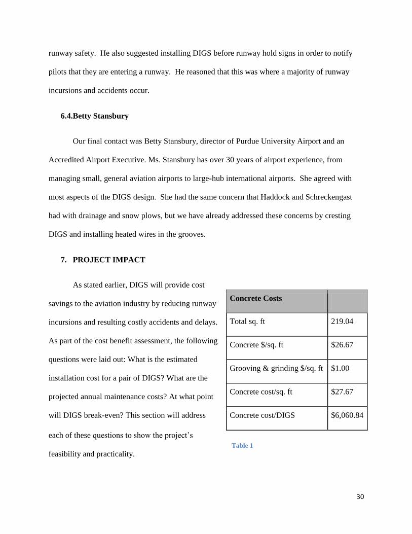
The cost of concrete for a DIGS is listed in Table 1. Each DIGS covers approximately 219.04
square feet. The prices of ultra-high strength concrete and grinding/grooving of the concrete
were estimated by one of our industry contacts and pavement engineer, Jason Weiss. The total
estimated cost for the materials, installation and labor of
the DIGS’ concrete is $6,060.84.
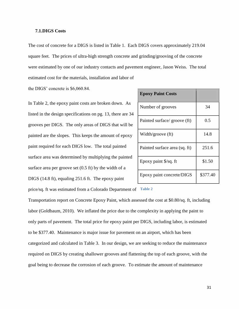
In Table 2, the epoxy paint costs are broken down. As
listed in the design specifications on pg. 13, there are 34
grooves per DIGS. The only areas of DIGS that will be
painted are the slopes. This keeps the amount of epoxy
paint required for each DIGS low. The total painted
surface area was determined by multiplying the painted
surface area per groove set (0.5 ft) by the width of a
DIGS (14.8 ft), equaling 251.6 ft. The epoxy paint
price/sq. ft was estimated from a Colorado Department of
Transportation report on Concrete Epoxy Paint, which assessed the cost at $0.80/sq. ft, including
labor (Goldbaum, 2010). We inflated the price due to the complexity in applying the paint to
only parts of pavement. The total price for epoxy paint per DIGS, including labor, is estimated
to be $377.40. Maintenance is major issue for pavement on an airport, which has been
categorized and calculated in Table 3. In our design, we are seeking to reduce the maintenance
required on DIGS by creating shallower grooves and flattening the top of each groove, with the
goal being to decrease the corrosion of each groove. To estimate the amount of maintenance
Epoxy Paint Costs
Number of grooves 34
Painted surface/ groove (ft) 0.5
Width/groove (ft) 14.8
Painted surface area (sq. ft) 251.6
Epoxy paint $/sq. ft $1.50
Epoxy paint concrete/DIGS $377.40
Table 2
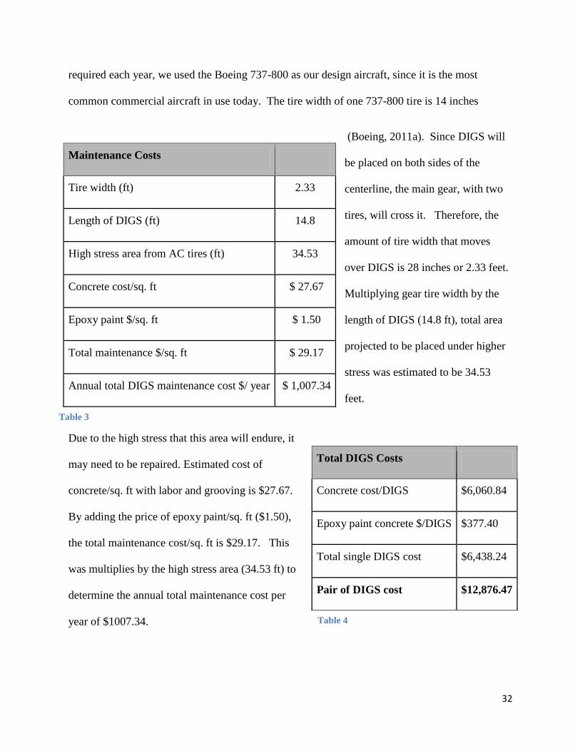
32
required each year, we used the Boeing 737-800 as our design aircraft, since it is the most
common commercial aircraft in use today. The tire width of one 737-800 tire is 14 inches
(Boeing, 2011a). Since DIGS will
be placed on both sides of the
centerline, the main gear, with two
tires, will cross it. Therefore, the
amount of tire width that moves
over DIGS is 28 inches or 2.33 feet.
Multiplying gear tire width by the
length of DIGS (14.8 ft), total area
projected to be placed under higher
stress was estimated to be 34.53
feet.
Due to the high stress that this area will endure, it
may need to be repaired. Estimated cost of
concrete/sq. ft with labor and grooving is $27.67.
By adding the price of epoxy paint/sq. ft ($1.50),
the total maintenance cost/sq. ft is $29.17. This
was multiplies by the high stress area (34.53 ft) to
determine the annual total maintenance cost per
year of $1007.34.
Maintenance Costs
Tire width (ft) 2.33
Length of DIGS (ft) 14.8
High stress area from AC tires (ft) 34.53
Concrete cost/sq. ft $ 27.67
Epoxy paint $/sq. ft $ 1.50
Total maintenance $/sq. ft $ 29.17
Annual total DIGS maintenance cost $/ year $ 1,007.34
Table 3
Total DIGS Costs
Concrete cost/DIGS $6,060.84
Epoxy paint concrete $/DIGS $377.40
Total single DIGS cost $6,438.24
Pair of DIGS cost $12,876.47
Table 4
33
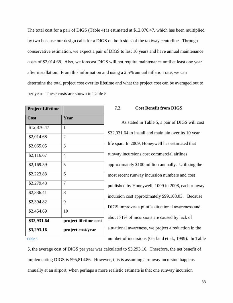
The total cost for a pair of DIGS (Table 4) is estimated at $12,876.47, which has been multiplied
by two because our design calls for a DIGS on both sides of the taxiway centerline. Through
conservative estimation, we expect a pair of DIGS to last 10 years and have annual maintenance
costs of $2,014.68. Also, we forecast DIGS will not require maintenance until at least one year
after installation. From this information and using a 2.5% annual inflation rate, we can
determine the total project cost over its lifetime and what the project cost can be averaged out to
per year. These costs are shown in Table 5.
7.2. Cost Benefit from DIGS
As stated in Table 5, a pair of DIGS will cost
$32,931.64 to install and maintain over its 10 year
life span. In 2009, Honeywell has estimated that
runway incursions cost commercial airlines
approximately $100 million annually. Utilizing the
most recent runway incursion numbers and cost
published by Honeywell, 1009 in 2008, each runway
incursion cost approximately $99,108.03. Because
DIGS improves a pilot’s situational awareness and
about 71% of incursions are caused by lack of
situational awareness, we project a reduction in the
number of incursions (Garland et al., 1999). In Table
5, the average cost of DIGS per year was calculated to $3,293.16. Therefore, the net benefit of
implementing DIGS is $95,814.86. However, this is assuming a runway incursion happens
annually at an airport, when perhaps a more realistic estimate is that one runway incursion
Project Lifetime
Cost Year
$12,876.47 1
$2,014.68 2
$2,065.05 3
$2,116.67 4
$2,169.59 5
$2,223.83 6
$2,279.43 7
$2,336.41 8
$2,394.82 9
$2,454.69 10
$32,931.64 project lifetime cost
$3,293.16 project cost/year
Table 5
34
happens within a 10 year timeline. Using this scenario, the net benefit of implementing DIGS is
$66,176.38.
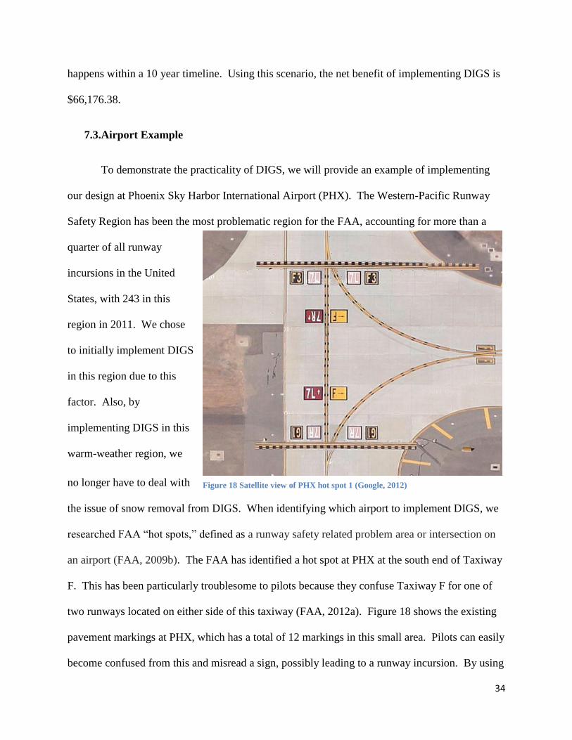
7.3.Airport Example
To demonstrate the practicality of DIGS, we will provide an example of implementing
our design at Phoenix Sky Harbor International Airport (PHX). The Western-Pacific Runway
Safety Region has been the most problematic region for the FAA, accounting for more than a
quarter of all runway
incursions in the United
States, with 243 in this
region in 2011. We chose
to initially implement DIGS
in this region due to this
factor. Also, by
implementing DIGS in this
warm-weather region, we
no longer have to deal with
the issue of snow removal from DIGS. When identifying which airport to implement DIGS, we
researched FAA “hot spots,” defined as a runway safety related problem area or intersection on
an airport (FAA, 2009b). The FAA has identified a hot spot at PHX at the south end of Taxiway
F. This has been particularly troublesome to pilots because they confuse Taxiway F for one of
two runways located on either side of this taxiway (FAA, 2012a). Figure 18 shows the existing
pavement markings at PHX, which has a total of 12 markings in this small area. Pilots can easily
become confused from this and misread a sign, possibly leading to a runway incursion. By using
Figure 18 Satellite view of PHX hot spot 1 (Google, 2012)

35
DIGS, four of these signs will be replaced by two signs. These two replacement signs, the
DIGS, will only display two information signs as opposed to four information signs, when
approaching from either runway. This is depicted in Figure 19. A simple replacement of
traditional pavement signs with DIGS can drastically improve runway safety by allowing the
pilot to understand his or her location on the airport.
Figure 19 Hot spot 1 with DIGS implementation
36
Appendix A
Professor Timothy Ropp
Phone: 765-494-9957
Fax: 765-494-2305
E-mail: [email protected]
Keaton Aktay
Undergraduate student
Phone: 219-644-6117
E-mail: [email protected]
Address:
9213 Birch Ave
Munster, IN, USA 46321
Jin Young Kim
Graduate student
Phone: 82-10-9290-7407
E-mail: [email protected]
Address:
234-1, Guin-ri, Jangan-myeon, Boeun-gun
Chungbuk, South Korea
37
Appendix B
Purdue University is a coeducational, state-assisted system in Indiana. Founded in 1869 and
named after benefactor John Purdue, Purdue is one of the nation's leading research institutions
with a reputation for excellent and affordable education. Purdue University is accredited by the
Higher Learning Commission of the North Central Association of Colleges and Schools. The
West Lafayette campus offers more than 200 majors for undergraduates, over 70 master’s and
doctoral programs, and professional degrees in pharmacy and veterinary medicine. Purdue
University’s College of Technology is one of the largest and most renowned technology schools
in the nation with more than 34,000 living alumni. More than 5,500 Purdue students are currently
pursuing their education in the College of Technology. The College of Technology consists of
eight academic departments, and resides in ten Indiana communities in addition to the West
Lafayette campus. The Aviation Technology department is one of the eight departments within
the College of Technology. Three undergraduate programs are offered within the department:
Aeronautical Engineering Technology, Aviation Management, and Professional Flight. Graduate
studies in Aviation Technology are also offered. In addition, the department pursues signature
research areas that embrace tenets of the emerging Next Generation Air Transportation System,
which include Hangar of the Future aircraft maintenance technology innovation, National Test
Facility for Fuels and Propulsion, and Safety Management Systems.

38
Appendix C
The DIGS research team did not have a non-university partner during the project.
39
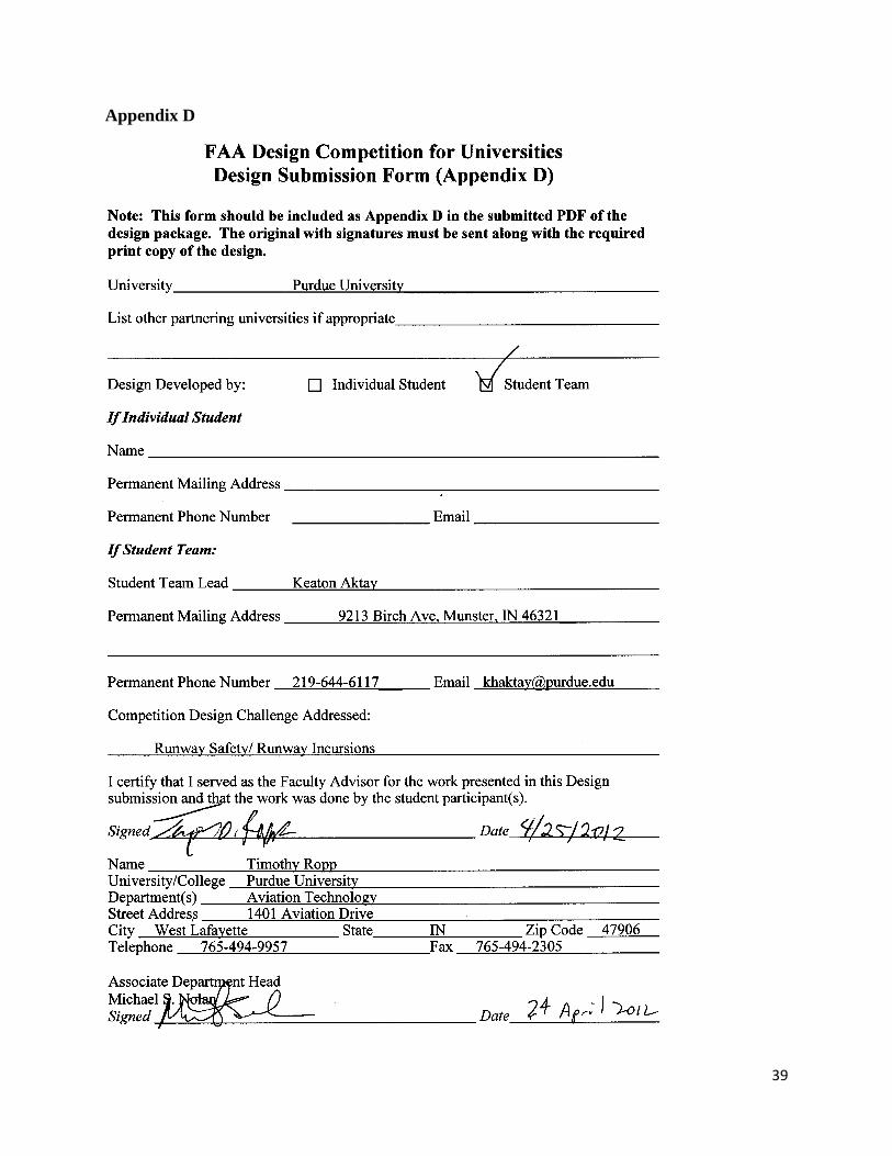
Appendix D

40
Appendix E
For student members:
1. Did the FAA Design Competition provide a meaningful learning experience for
you? Why or why not?
The FAA Design Competition did provide a meaningful experience for our research
team. Experiencing firsthand the problems that major airlines, airports and government officials
encounter was eye-opening. The number of challenges and obstacles that these parties deal with
daily has helped us understand how and why the industry it is today.
2. What challenges did you and/or your team encounter in undertaking the
Competition? How did you overcome them?
Our greatest challenge was determining the cost and the benefit of the project. To
overcome this challenge we reached out to professionals outside of aviation in order to gain a
better understanding of pavement costs. The other challenge that our team had was time
management and handling a project of this magnitude with team of only two students. We
solved this problem by meeting weekly and utilized technology like Google Docs to update each
other on the progress of the project. During the final two weeks, we met every other day to
ensure project was completed on time.
3. Describe the process you or your team used for developing your hypothesis.
To first develop our problem background, we investigated the areas within aviation that
needed drastic improvement. We saw that runway safety was major issue and to improve it,
there needed to be a new, cost-effective design. Then, we collaborated with industry
professionals to understand the main causes to the problem that we were addressing and to
receive feedback on our design. Next, we took the industry’s suggestions and looked at the areas
41
that needed to be developed more. Lastly, we assessed the practicality of our design and whether
or not the majority of the industry would find it useful.
4. Was participation by industry in the project appropriate, meaningful and useful? Why
or why not?
Our interaction with industry professionals was vital to tailoring and adjusting our project
to make it more feasible and realistic. We reached out to professionals outside of aviation in
order to gain feedback on topics with which were not familiar. We believe that this was very
appropriate, and we suggest that future participants in the competition do the same.
5. What did you learn? Did this project help you with skills and knowledge you need to be
successful for entry in the workforce or to pursue further study? Why or why not?
We enhanced our research and critical thinking skills through identifying the research
problem, assessing current practices, determining a solution, and defining the impact of
project. By working with a smaller research group, we learned to always review each other’s
answers and conclusions. We believe these skills will be essential to our careers in
aviation. Overall, it has been a very rewarding experience, and we recommend college students
to participate in the competition.
For faculty members:
l. Describe the value of the educational experience for your student(s) participating in this
competition submission.
This project had an innovation concept that stretched the students to pursue patent and existing
technology identification during their literature/technology review. The team was forced to have
42
continuous collaboration and diligence in fact finding as they developed their idea; this included
meeting design challenges put forth by others to prove the viability of their idea and re-design.
2. Was the learning experience appropriate to the course level or context in which the
competition was undertaken?
The student team’s experience was salient and appropriate to the R&D within the Hangar of the
Future laboratory at the University, and the type of innovation and problem solving being looked
at within the Next Generation Air Transportation System in the air transportation industry.
Students were able to utilize the Department’s large aircraft and ramp area for visualization,
prototype development and initial testing, which is exactly what our real world large aircraft
laboratory is designed for. There was an excellent use of the aircraft, airframe lab and real airport
workspace. As a team comprised of an undergraduate and graduate, this was an excellent
example of moving from coursework knowledge to applied (hands-on) real-world application.
3. What challenges did the students face and overcome?
They discovered some preexisting design similarities forcing the team to critically evaluate their
own ideas, what the true outcome of their design was to enable, and identify specific differences
and improvements. They had to ask the critical 3rd
and 4th
questions like, “beyond just being a
slick idea, WHO will it serve, HOW WELL compared to existing methodologies, how robust is
the design and what MULTI-USE capabilities could there be?”
43
4. Would you use this Competition as an educational vehicle in the future? Why or why
not?
Definitely would use this competition and the type of questions and research it drives. In fact this
competition is a natural and relevant outlet to the style of education and problem solving I strive
for in my Aeronautical Engineering Technology courses, which are heavy in applied knowledge,
experimentation, literature and technology review and applications, immersive learning etc.
5. Are there changes to the Competition that you would suggest for future years?
Our concern is one that has been shared before however it is not all bad. That would be that it is
nerve wracking to determine if the team’s idea presented is not already in existence somewhere
which was not discovered during the in the literature and technology reviews (was due diligence
followed deeply enough for the time allotted?). I believe this is positive, in that it teaches the
importance of deep research and the ethical decision making of acknowledging professionally
others’ previous work. Glad to see the addition of new topics and would encourage you to
continue opening design ideas that incorporate cross-disciplinary collaboration between different
operations (Ramp, Gate, Tower etc.).
44
Appendix F
Adams, J. (2008, July 30). ASDE-X and runway status lights [PDF document]. Retrieved from
Presentation Slides Online Web site: http://www.lawa.org/uploadedfiles/lax/pdf/ASDE-
X%20and%20Runway%20Status%20Lights%20%28Jake%20Adams%29.pdf.
Department of Transportation. (1995). FHWA bridge coatings technical note: Epoxy mastic
bridge coatings. Retrieved from http://www.fhwa.dot.gov/publications/research/
infrastructure/structures/bridge/mastic.cfm.
Department of Transportation. (2008, February 13). Actions needed to improve runway safety.
Retrieved from http://www.cast-safety.org/pdf/dot_ig_rwy_safety_2008.pdf.
Federal Aviation Administration. (2007, February 27). Introduction to safety management
systems (SMS) for airport operators (AC 150/5200-37). Retrieved from http://www.
faa.gov/airports/resources/advisory_circulars/index.cfm/go/document.current/
documentNumber/150_5200-37.
Federal Aviation Administration. (2009a, March 25). Fact sheet - aviation industry responds to
FAA’s runway safety call to action.. Retrieved from http://www.faa.gov/news
/fact_sheets/news_story.cfm?newsId=10133.
Federal Aviation Administration. (2009b, December 18). Focus on hot spots (FAA Publication
No. OK 90-3619). Washington, DC: U.S. Government Printing Office.
45
Federal Aviation Administration. (2010a, November 11). Annual runway safety report 2010.
Retrieved from http://www.faa.gov/airports/runway_safety/news/publications/media
/Annual_Runway_Safety_Report_2010.pdf.
Federal Aviation Administration. (2010b, November 17). Standards for airport markings (AC
150/5340-1K). Retrieved from http://www.faa.gov/regulations_policies
/advisory_circulars/index.cfm/go/document.information/documentID/386812.
Federal Aviation Administration. (2011a, March 29). Airside use of heated pavement system.
(AC 150/5370-17). Retrieved from http://www.faa.gov/airports/resources/advisory_
circulars/index.cfm/go/document.information/documentNumber/150_5370-17.
Federal Aviation Administration. (2011b, September 22). National Runway Safety Plan.
Retrieved from http://www.faa.gov/airports/runway_safety/news/publications/media/
2011_ ATO_Safety_ National_Runway_Safety_Plan.pdf.
Federal Aviation Administration. (2012a, April 5). Airport Diagram. 452-458. Retrieved from
http://aeronav.faa.gov/pdfs/SW_hotspot_05Apr2012.pdf.
Federal Aviation Administration. (2012b, April 17). Runway incursion totals by quarter FY2009
vs. FY2008. Retrieved from http://www.faa.gov/airports/runway_safety/statistics/year/
?fy1=2009&fy2=2008.
46
Federal Aviation Administration. (2012c, April 17). Runway incursion totals by quarter FY2012
vs. FY2011. Retrieved from http://www.faa.gov/airports/runway_safety/statistics/year/
?fy1=2012&fy2=2011.
Garland, D. J., Wise, J.A., and Hopkin, V.D. (Eds.) (1999). Handbook of Aviation Human
factors, 258-273. Mahwah, NJ: Lawrence Erlbaum Associations.
Goldbaum, J. (2010, January). Cost-benefit evaluation of enhanced specifications for epoxy
pavement marking material. Retrieved from http://www.coloradodot.info/programs/
research/experimentalfeatures/epoxypavementmarking.pdf.
Honeywell. (2009, May). Honeywell Smartrunway and Smartlanding: Reducing the risk of
runway incursions and excursions. Retrieved from https://honeywellrunwaysafety
.com/images/RunwaySafety_INTB_FINAL.pdf.
National Transportation Safety Board. (2012). Most wanted list. Retrieved from
http://www.ntsb.gov/safety/mwl.html.
Phoenix International Airport, AZ. (2012). Google Maps. Google. Retrieved from
http://maps.google.com/maps/place?q=phx&hl=en&cid=9436507786966396482.

47
Shah, P. S., & Weiss, W.J. (1998). Ultra high strength concrete: A look to the future. Retrieved
from https://engineering.purdue.edu/~concrete/weiss/publications/r_conference/RC-
011.pdf.
The Boeing Company. (2011a, May). 737 aircraft characteristics for airport planning. Retrieved
from http://www.boeing.com/commercial/airports/acaps/737.pdf.
The Boeing Company. (2011b, May) 747 aircraft characteristics for airport planning. Retrieved
from http://www.boeing.com/commercial/airports/acaps/747_4.pdf.
The Boeing Company. (2011c, May) 777 aircraft characteristics for airport planning. Retrieved
from http://www.boeing.com/commercial/airports/acaps/777_2.pdf.
The MITRE Corporation. (2004, July 28). 3-D runway surface marking. Retrieved from
http://www.mitrecaasd.org/work/project_details.cfm?item_id=141.
Weiss, A & Pilossf, N. (2004, March 4). U.S. Patent No. 791,726. Washington, D.C: U.S. Patent
and Trademark Office.
48
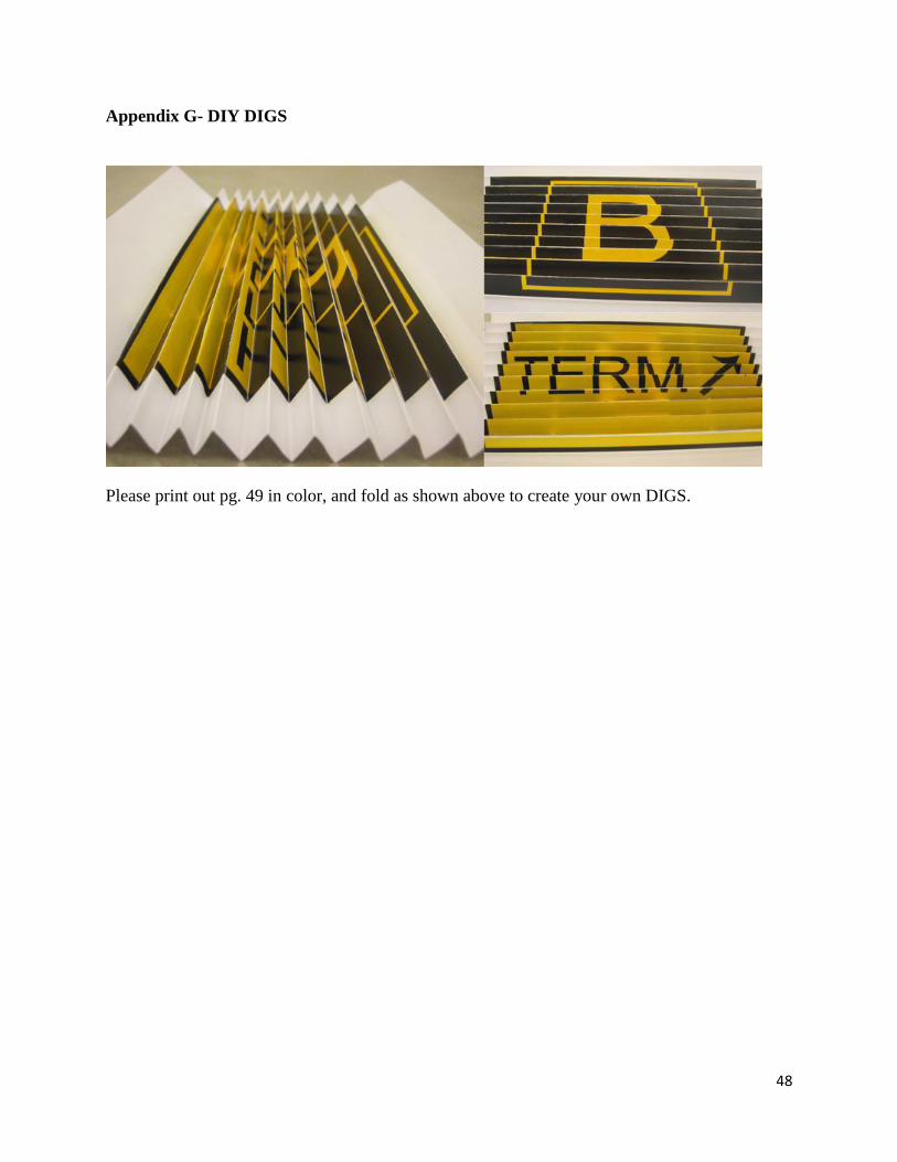
Appendix G- DIY DIGS
Please print out pg. 49 in color, and fold as shown above to create your own DIGS.

49