dts0055 - optical delay lines · 2020-01-28 · optical delay lines ... the light travels in free...
TRANSCRIPT
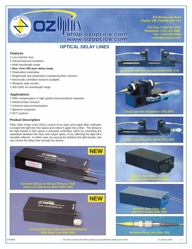
OPTICAL DELAY LINESFeatures• Low insertion loss• Sub-picosecond resolution• Wide wavelength range• New: Over 600 psec delay range• Polarization insensitive• Singlemode and polarization maintaining fiber versions• Electrically controlled versions available• Miniature style version• 400–2000 nm wavelength range
Applications• PMD compensation in high speed communications networks• Interferometric sensors• Coherent telecommunications• Spectrum analyzers• OCT systems
Product DescriptionFiber Optic Delay Lines (ODL) consist of an input and output fiber collimatorto project the light into free space and collect it again into a fiber. The distancethe light travels in free space is precisely controlled, either by controlling theseparation between the input and output optics, or by reflecting the light off amovable reflector. In either case, by varying the distance the light travels, onecan control the delay time through the device.
Delay Line with Manual Lead Screw (ODL-100)
Reflector Style Delay Line with Manual Lead Screw (ODL-600)
Delay Line with Micrometer (ODL-200)
Delay Line with Servo Motor (ODL-300)
Miniature Delay Line (ODL-700)
DTS0055 OZ Optics reserves the right to change any specifications without prior notice. 21 January 2020 1
Reflector Style Delay Line with Servo Motor (ODL-650)
Extended (330 ps or 600 ps) Manual ReflectorStyle Delay Line (ODL-600)
NEW
Extended (330 ps or 600 ps) Reflector Style Delay Line with Servo Motor (ODL-650)
NEW
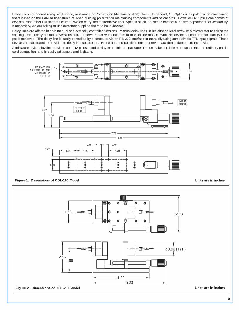
Figure 1. Dimensions of ODL-100 Model
Figure 2. Dimensions of ODL-200 Model
2
Delay lines are offered using singlemode, multimode or Polarization Maintaining (PM) fibers. In general, OZ Optics uses polarization maintainingfibers based on the PANDA fiber structure when building polarization maintaining components and patchcords. However OZ Optics can constructdevices using other PM fiber structures. We do carry some alternative fiber types in stock, so please contact our sales department for availability.If necessary, we are willing to use customer supplied fibers to build devices.Delay lines are offered in both manual or electrically controlled versions. Manual delay lines utilize either a lead screw or a micrometer to adjust thespacing. Electrically controlled versions utilize a servo motor with encoders to monitor the motion. With this device submicron resolution (<0.003ps) is achieved. The delay line is easily controlled by a computer via an RS-232 interface or manually using some simple TTL input signals. Thesedevices are calibrated to provide the delay in picoseconds. Home and end position sensors prevent accidental damage to the device. A miniature style delay line provides up to 13 picoseconds delay in a miniature package. The unit takes up little more space than an ordinary patch-cord connection, and is easily adjustable and lockable.
Units are in inches.
Units are in inches.

2-56 UNC TAPPED
3.42” [87mm] (REF)
0.40” [10.2mm]Delay Adjustment Knob
Delay Lock Nut
Figure 5. Dimensions of ODL-700 Model
Figure 3. Dimensions of ODL-300 Model
3
Figure 4. Dimensions of ODL-600 Model
Units are in inches.
Units are in inches.
Units are in inches.
2-56 UNC TAPPED
4.12
4.00
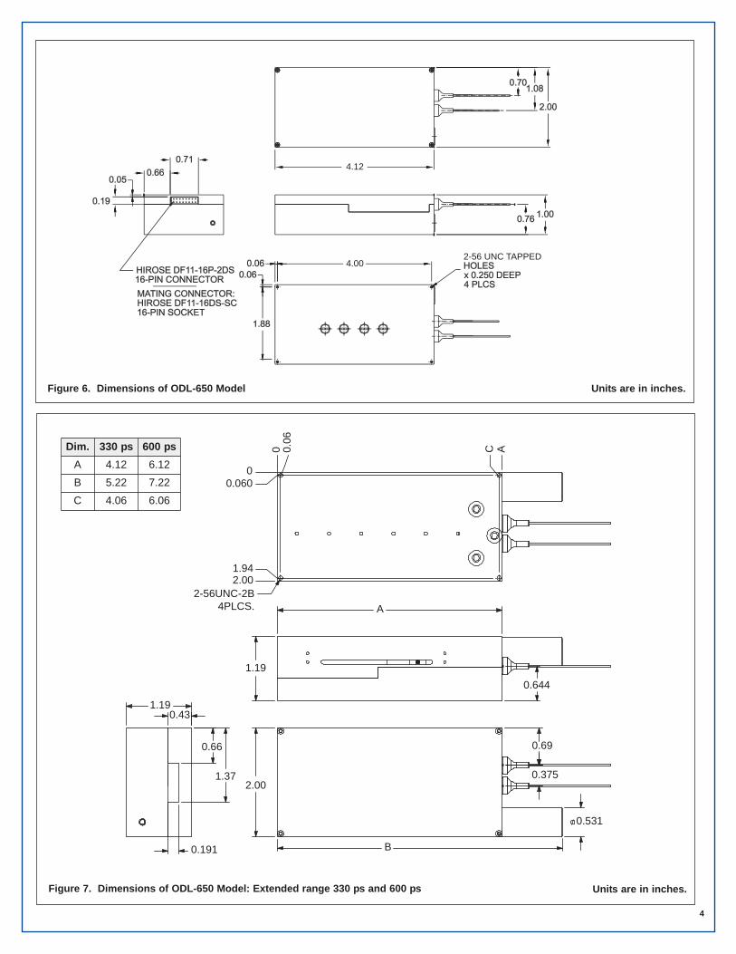
Figure 6. Dimensions of ODL-650 Model
4
2.00
B
0.531
0.69
0.375
1.19 0.43
0.66
1.37
0.191
A
1.19 0.644
2-56UNC-2B4PLCS.
0
0.0
6
C
A
0 0.060
1.94 2.00
Figure 7. Dimensions of ODL-650 Model: Extended range 330 ps and 600 ps
Units are in inches.
Units are in inches.
Dim. 330 ps 600 psA 4.12 6.12B 5.22 7.22C 4.06 6.06

Bar Code Part Number Description
13757 ODL-650-11-1550-8/125-P-60-3A3A-1-1-MC/RS232 Electrically Controlled Reflector Style Variable Fiber Optic Delay Line for 1550 nm, with 60 dB return loss. Pigtails are 1 meter long, 8/125 PM fibers, protected with 0.9 mm OD hytrel tubing, and with FC/APC connectors, RS232 Interface.
Ordering Examples For Standard PartsA customer is building a polarization mode dispersion compensator using a polarization maintaining electrically controlled delay line and com-puter interface. The delays in their system are 50 picoseconds or less. His system is sensitive to both insertion losses and return losses, so alow return loss device is needed.
5
Bar Code Part Number Description
9432 ODL-100-11-1550-9/125-S-60-3A3A-3-1 Variable Fiber Optic Delay Line for 1550 nm, with manual lead screw and 60 dB return loss. Pigtails are 1 meter long, 3 mm OD PVC cabled 9/125 SM fibers, FC/APC connectors.
13421 ODL-100-11-1550-8/125-P-60-3A3A-3-1 Variable Fiber Optic Delay Line for 1550 nm, with manual lead screw and 60 dB return loss. Pigtails are 1 meter long, 3 mm OD PVC cabled 8/125 PM fibers, FC/APC connectors.
10468 ODL-200-11-1550-8/125-P-60-3A3A-1-1 Variable Fiber Optic Delay Line for 1550 nm, with manual micrometer and 60 dB return loss. Pigtails are 1 meter long, 8/125 PM fibers, protected with 0.9 mm OD hytrel tubing, and with FC/APC connectors.
14645 ODL-600-11-1550-9/125-S-60-3A3A-1-1 Reflector Style Variable Fiber Optic Delay Line for 1550 nm, with manual lead screw and 60 dB return loss. Pigtails are 1 meter long, 0.9 mm OD tight buffered 9/125 SM fibers, FC/APC connectors.
13755 ODL-600-11-1550-8/125-P-60-3A3A-1-1 Reflector Style Variable Fiber Optic Delay Line for 1550 nm, with manual lead screw and 60 dB return loss. Pigtails are 1 meter long, 8/125 PM fibers, protected with 0.9 mm OD hytrel tubing, and with FC/APC connectors.
13756 ODL-650-11-1550-9/125-S-60-3A3A-1-1-MC/RS232 Electrically Controlled Reflector Style Variable Fiber Optic Delay Line for 1550 nm, with 60 dB return loss. Pigtails are 1 meter long, 0.9 mm OD tight buffered 9/125 SM fibers, FC/APC connectors, RS232 Interface.
13757 ODL-650-11-1550-8/125-P-60-3A3A-1-1- MC/RS232 Electrically Controlled Reflector Style Variable Fiber Optic Delay Line for 1550 nm, with 60 dB return loss. Pigtails are 1 meter long, 8/125 PM fibers, protected with 0.9 mm OD hytrel tubing, and with FC/APC connectors, RS232 Interface.
Ordering Information For Standard Parts For more Standard Parts, please see our Online Catalog http://shop.ozoptics.com
Figure 8. Dimensions of ODL-600 Model: Extended range 330 ps and 600 ps Units are in inches.
2.00
B
0.69
0.375
0.497
1.19 0.43
A
1.19
0.644
2-56UNC-2B4PLCS.
0
0.0
6
C
A
0 0.06
1.94 2.00
Dim. 330 ps 600 psA 4.12 6.12B 4.80 6.80C 4.06 6.06

6
Environmental Specification For Singlemode Or PM ODL-650 Systems At 1550 nm
Operating Temperature (°C) -10°C to +60°C
Temperature Dependent Loss (Measured over the Entire Scanning Range)
<1 dB from +10°C to +40°C <2 dB from -10°C to +60°C
Operating Lifetime Over 5000 hours, continuous operation
Standard Product SpecificationsTable 1. Manual delay line
Table 2. Motorized delay line
1 Theoretical, based on thread pitch and motor/encoder resolution. The MC/RS232 versions of the ODL-300 and ODL-650 can generate twocounts per encoder pulse, effectively doubling the resolution.
2 Includes variation of insertion loss over the entire travel range.3 For 1550 nm wavelengths singlemode or PM fibers, at room temperature.4 ODL-600 and ODL-650 delay lines are offered with 167 psec delay range as standard, or 330 psec, or 600 psec as an option.5 An 8 mm/sec version is offered.6 This is the maximum speed. The speed may be programmed to a lower value by the user.

Application NotesExample Application: Polarization mode dispersion (PMD) is an important issue in the quest to build high speed (10GBs, 40GBs, and high-er) communication networks. An input signal travelling along a single mode fiber normally has some distortion, due to polarization mode dis-persion. The signal effectively has been split into two arbitrary, yet orthogonal polarizations, and one polarization is leading the other. A delayline is a crucial element in building compensators for PMD.The figure below shows how to use a delay line to compensate for polarization modes dispersion. The light from the singlemode input is splitinto two using a polarizing beam splitter. A polarization controller installed just before the splitter is used to convert the arbitrary polarizationsthat the signal has been split into S and P polarization. The faster S polarization is routed through the delay line while the slower P polariza-tion is sent straight into the combiner. The combined signals then reach the receiver. A control system monitors the quality of the signal atthe receiver, and dynamically adjusts the polarization and the delay to get the two signals to match up again. Thus the PMD is in the systemcan be corrected in real time. 7
Part Number Description
ODL-650-11-1300-9/125-S-60-XX-1-1,10 -MC/RS232-330
Electrically controlled reflector style variable fiber optic delay line for 1300 nm with 60 dB return loss. Pigtails are 1 meter long on the input, 10 meters long on the output 0.9 mm OD hytrel jacketed 9/125 singlemode fibers, no connectors. Unit comes with a RS232 interface, 330 psec delay range.
Ordering Examples For Custom PartsA customer building an interferometer needs a motorized reflector style delay line for 1300 nm, using singlemode fiber. He needs pigtails 1 meter long on one side, and 10 meters long on the other side, and does not need connectors. Because he is fusion splicing, he prefersuncabled fiber. He needs as long a travel range as possible at least 250 psecond. Return losses do need to be as low as possible, to preventadditional interference effects. He will control with RS232 commands.
ODL-A-11-W-a/b-F-LB-XY-JD-L(-I)
A = Version:100 = Standard Style, with lead screw200 = Standard Style, with micrometer300 = Standard Style, with DC servo motor600 = Reflector Style, with lead screw*650 = Reflector Style, with Servo motor*700 = Miniature Style* at the end of the part number add
- 330 for 330 ps option- 600 for 600 ps option
(available for 1550 nm, 1310 nm, and1064nm)
L = Fiber length, in meters, on each side ofthe device.Example: To order 1 meter of fiber at theinput and 7 meters at the output, replace theL with 1,7
W = Wavelength: Specify in nanometers(Example: 1550 for 1550 nm)
a/b = Fiber core/cladding sizes, in microns,9/125 for 1300/1550 nm SM fiber sizes8/125 for 1550 nm PM fiber sizesSee Tables 1 to 5 of the Standard Tableshttps://www.ozoptics.com/ALLNEW_PDF/DTS0079.pdfdata sheet for other fiber sizes
F = Fiber type: M=MultimodeS=SinglemodeP=Polarization maintaining
LB = Backreflection level: 40 dB for wavelength outside 1300–1550 nm. 60dB for1300 and 1550 nm only. Multimode devicesare only available with 35 dB.
JD = Fiber Jacket type:1 = 900 micron OD hytrel jacket3 = 3 mm OD kevlar reinforced PVC cable
See Table 7 of the Standard Tableshttps://www.ozoptics.com/ALLNEW_PDF/DTS0079.pdffor other jacket sizes.
X,Y = Input & Output Connector Codes:X = No connector3S = Super NTT-FC/PC3U = Ultra NTT-FC/PC3A = Angled NTT-FC/PC8 = AT&T-STSC = SCSCA = Angled SCLC = LCLCA = Angled LCMU = MU
I = Interface (ODL-300 & 650 models only)MC/RS232 for Intelligent RS232 Interfacewith built-in manual TTL control linesPC for direct connections to the motor, encoder and limit switches (no driver).
Ordering Information For Custom PartsOZ Optics welcomes the opportunity to provide custom designed products to meet your application needs. As with most manufacturers, cus-tomized products do take additional effort so please expect some differences in the pricing compared to our standard parts list. In particular, wewill need additional time to prepare a comprehensive quotation, and lead times will be longer than normal. In most cases non-recurring engi-neering (NRE) charges, lot charges, and a 1 piece minimum order will be necessary. These points will be carefully explained in your quotation,so your decision will be as well informed as possible. We strongly recommend buying our standard products.
Questionnaire For Custom Parts1. What Delay Range (in psec or mm) do you need?2. What Resolution (in psec or mm) do you need?3. Do you need a readout of the position?4. Do you need electrical control?5. Do you need computer control? What Interface will you use?6. Do you intend to make your own drive circuit?
7. What wavelength will you be using?8. What fiber type are you using? Singlemode, Multimode or
Polarization Maintaining?9. What is the worst acceptable return loss?
10. What kind of fiber connectors are you using?

8
Frequently Asked Questions (FAQs)Q: How do I convert travel in mm to delays in picoseconds?A: The delay is equal to the distance divided by the speed of light in
air. 1 mm corresponds to 3.33 psec of delay. Note that in the ODL-600 and ODL-650 models, the light travels the distance twice, sothe delay is twice the motion of the optics.
Q Is the minimum delay zero picoseconds?A: No, there is a minimum delay, due to the minimum separation
between the optics, and the length of the attached fibers. A onemeter long fiber produces a 4.9 nsec delay. The minimum separa-tion of the optics induces between 30 psec and 150 psec delay,depending on the model. The delay range specified in the tablesis for relative delay.
Q: Are the units calibrated?A: The ODL-200 models have a micrometer, to give the direct read-
out of the motion, in mm. The ODL-300 with controller and ODL-650 also give a readout of the delay in picoseconds. The othermodels do not have any calibration. Note that these are relativereadouts, not absolute (see the previous question).
Q: What are the advantages and disadvantages of the inline versionversus the reflector style?
A: Generally the inline version gives the largest travel ranges versusthe reflector style, and thus can produce the greatest delays.However the reflector style unit has the advantage that the fibersthemselves do not move. This makes the reflector style the bestchoice for commercial applications as opposed to lab use.
Q: Do I need special software to run the ODL-300 or ODL-650 delaylines?
A: Both units are operated with simple text commands that can besent via terminal programs such as Windows™ Hyperterminal™. Active X™ control and Labview™ driver, as well as a directWindows interface program are also provided.
Q: What voltages and currents do the motor driven delay lines use?A: The ODL-300 requires an input voltage between 7 to 12 Volts, and
can draw on the order of 400 mA of current when the motor is turn-ing. The ODL-650 also requires 7 to 12 Volts, and can draw on theorder of 200 mA of current when operating. If you have specialrequirements please contact OZ Optics.
Mounting: The base of the delay lines have mounting holes for attachment to a rack or printed circuit board. For best results, the mounting surface should be rigid and free of vibration. Do not over-tighten the mounting screws and use screws that thread in no more than 2 mm. Tightening the mounting screws too much will warp the base and potentially increase losses either temporarily or permanently.
When you first connect the wire harness to the 16-pin port, make sure that the power is off. Before turning the power on, make sure that yourconnections have the correct voltage levels and polarity (given above). If you have ordered an RS-232 interface, the harness comes terminatedwith a DB9 connector that plugs directly into your computer's serial port. For special applications, the harness is left without a connector and mustbe terminated by the user for the communications type of their choice.
(1) (3) (5) (7) (9) (11) (13) (15)(2) (4) (6) (8) (10) (12) (14) (16)
Hirose 16-pin connector
Electrical Connections: The ODL-650 unit has a Hirose DF11-16P-2DS16-pin connector. The pin designations are given below:
Pin Name Function Comment 1 GND Common Ground 2 GND Common Ground 3 Select Select TTL interface For TTL interface, Input Active Low
4 Vin Input DC supply voltage; (Min +7 V Max +12 V)
For ODL-300 Typ. 400 mA For ODL-650 Typ. 200 mA
5 Reverse Move the motor in reveres For TTL interface, Input Active Low 6 Rx RS232- Receive input line 7 Forward Move the motor forward For TTL interface, Input Active low 8 Tx RS232- Transmit output line 9 N/A Do not connect Factory use 10 N/A Do not connect Factory use 11 Reset Hardware Reset line Active Low, Min 100 mS 12 N/A Do not connect Factory use 13 End End limit switch TTL output, active low 14 N/A Do not connect Factory use 15 Home Home limit switch TTL output, active low 16 N/A Do not connect Factory use
Figure 9. PMD Compensation System Using a Variable Delay Line