dtic · - superimposed load test (stackability with dunnage), iaw method 5016.1 of ftms 101c. -...
TRANSCRIPT
® / APPROVED FOR PUBLIC RELEASE PTPD REPORT NO. 83-R-02
DISTRIBUTION UNLIMITED AFPEA PROJE^ NO. 82-P7-68
Q WILLIAM G. MOSS or Mechanical Engineer
AUTOVON 787-3362
Commercial (513) 257-3362
TEST AMD EVALUATION OF METHOD II, GAU-8 30M
AMMUNITION CONTAINERS
Hq AFALO/PTPO AIR FORCE PACKAGING EfAltJATIOf AGENCY
Uj Wrtght-Patttrson AFB OK 4S433
DTIC ELECTE^
AU8 39 ©B :* |
Ay§ytt 1983
83 08 22 039
NOfSCi
When government drawings, specifications, or other datu ssrt' ustd for any purple other than in connwli»n with m definitely related government procurement operation, the United States Government thereby incur® no responsi- bility whatsoever; and the fact that the government may have formulated, furni«hed, or in any way supplied the said drawings, specifications, or other data, m not to be regarded by implication or otherwise as in any manner licensing the holder or any other person or corporation, or conveying any rights or perfnkmon to manufacture, use, or seSB any patented invention that may in any way be related thereto. This report its not to be used in whole or in part for advertising or ualet purposm.
ABSTRACT
On 23 Dec 83, six Method II, GAU-8 30mm ammunition containers were received by the Air Force Packaging Evaluation Agency (AFPEA) for qual- ification testing. Upon initial inspection, the containers failed to meet the specification requirements for hand-lift-truck compatibility. The containers were returned to the manufacturer, Lanson Industries, for modification. The modified containers arrived back at AFPEA on 6 Jan 83. Testing commenced on 10 Jan 83. After two more modifications to the container and several changes in the testing sequence and procedures, the testing successfully concluded on 24 Mar 83.
During testing, three major deficiencies in the container design affecting useability and reliability were discovered. First, the width of the container lids was excessive. When two containers were pinned together in their normal shipping I handling configuration, no clear- ance existed between the lids. If the container lids were removed, they could not easily be reinstalled. Second, two of the six bolts used as fasteners for the Hds failed after only four operations. Finally, the desiccant port covers were very susceptible to permanent damage requiring replacement from minor impacts.
On 18 Apr 83, two additional containers were delivered to AFPEA with design changes intended to correct these deficiencies. The problems with the fasteners and the desiccant port cover were corrected. The problem of insufficient clearance between the lids of the containers in their normal configuration still exists. This condition will cause some operational problems in the field. To completely eliminate any problems would require a reduction in the container lid width necessary to ensure the desired clearance with required changes in the fastener locations, flange design and seal* as well as the lid. These changes should be incorporated into the design, prior to delivery.
WILLIAH G. MOSS, Mechanical Engineer Design Division AF Packaging Evaluation Agency
RSVIEWEO §¥:
RALPH ZYIf Chief, Design Air Force Packaging Evaluation Agency
m ©Afl:
01A0ftf983
mm fif Force Packaging
Evaluation Agency

TABLE OF CONTENTS
Page
Abstract
Table of Contents i
Introduction
Purpose
Background
Approach
Test Procedures , 2
Test Equipment and Instrumentation 3
Test Specimens 3
Test Results 4
Discussion 4
Conclusions 7
Recommendations 8
Distribution List 25
DD Form 1473 26
Illustrations
Figure 1. Container in pinned configuration forming test unit. 9
Figure 2. Container loaded with 30mm ammunition and link tube
carriers 10
Figure 3. Original containers incompatible with hand-lift-truck 11
Figures 4 15. The first test unit 12
Figure 6. Containers modified for pendulum-Impact test . . .13
Figure 7. Relocating locking pins due to pendulum-impact test , 14
Figure 8. Restraining system of the Initial vibration test.. , 15
Figures 9, 10, 11 I 12. Container damaged from first vibration
test 16
11

Page
Figure 13. Improved restraint system for vibration test ... 17
Figure 14. Modified forkwell 18
Figure 15. Scuffed Mylar 19
Figure 16. Humidity test results 20
Figures 17 & 18. Damage to containers from four-foot free fall
drop test IAW 49 CFR 21
Figures 19 & 20. Misaligned lid fasteners 22
Figure 21. Wear spots on lid of latest version 23
Figure 22. Misalignment of end bolt on lid fastener 24
Accession For
BTIS GRA&I DTIC TAB Unannounced Justification—
Distribution/
^ n n
Availability Codes JAvail and/or
Special
111
INTRODUCTION
PURPOSE: These tests were performed at the request of 00-ALC/DSTD to qualify a sealed, Method II version of the GAU-8/A ALS 30mm ammunition container for worldwide shipment, storage and handling.
BACKGROUND: The sealed, Method II version of the GAU-8/A ALS container, hereafter referred to as the CNU-383, is intended to be used for storage of new production WRM 30mm ammunition and as a replacement container for two earlier versions of the 30mm ammunition container currently used for WRM storage, the CNU-309 and the CNU-332. The CNU-309 and CNU-332 con- tainers have been in service for five and three years respectively.
The CNU-309, CNU-332, and the CNU-383 are very similar in appearance. In fact, the bodies of the containers are built to the same construction specification. The differences in the three containers are primarily in the methods of lid attachments, wheVier or not a seal is present in the lid, and whether there are drain holes in the container bottoms. The CNU-309, although not a hermetically sealed container, does have a soft foam seal in the lid and no drainage holes in the bottom. The lid, which is of a heavier gage metal, is attached to the container body by two quick-acting latches, one on each end.
The CNU-332 is considered a free breathing container. The lid has no seal and is attached to the container body by four bolts through the top of the lid, two on each long side. Six half-inch holes drilled in the bottom of the container prevent water from accumulating inside the container, The CNU-383 is hermetically sealed with a hard rubber gasket in the lid. The lid is attached by six bolts, one on each end and two passing through the top and seal on each side. Also, on one end of the container body, a breather valve, desiccant port and cover, and humidity indicator have been added.
APPROACH
The qualification requirements for the CNU-383 were developed by 00-ALC/DSTD and supplied through ASD/TAAX. Upon reviewing these testing requirements and comparing them to the probable handling environment encountered by the containers, a more appropriate testing procedure was developed. The series of tests used for qualifying the CNU-383 for use is as follows:
- Leaks in Container, Pneumatic Pressure Techniques IAW Method 5009.1, of Federal Test Method Standard (FTMS) 101C and MIL-STD-648.
- Cornerwise (Rotational) Drop Test, IAW Method 5005.1 of FTMS 101C. - Free Fall Drop Test, IAW Method 5007.1, Procedure B of FTMS 101C,
further qualified as only one drop to container bottom from twelve inches.
- Edgewise Drop (Rotational) Test, IAW Method 5008.1 of FTMS 101C. - Tipover Test, IAW Method 5018 of FTMS 101C. - Pendulum-Impact Test, IAW Method 5012 of FTMS 101C. - Mechanical Handling Test, IAW Method 5011.1, Procedure 6.2, Lifting
and Transporting by Forklift Truck and Procedure 6.3.2, Sling Handling with Attachments of FTMS 101C.

- Superimposed Load Test (Stackability with Dunnage), IAW Method 5016.1 of FTMS 101C.
- Superimposed Load (Uniformly Distributed), IAW Method 5017 of FTMS 101C.
- Vibration (Repetitive Shock) Test, IAW Method 5C19.1 of FTMS 101C. - Leaks in Container, Pneumatic Pressure Technique, IAW Method 5009.1
of FTMS 101C. - Rain Test, IAW Method 506.1, Procedure I of MIL-STD-810C. - Humidity Test, IAW Method 507.1, Procedure V of MIL-STD-810C. - Four-Foot Free Fall Drop Test, IAW 49 CFR, Paragraph 173.398 (b)
(3) (11).
TEST PROCEDURES
TEST NO. 1 (Leaks in Container) - This test was conducted in accordance with Method 5009.1, Procedure 6.3"Pneumatic Pressure Technique of FTMS 101. The testing pressure of 1.5 ± 0.5 psid and failure criteria of 0.05 psi loss in one hour as required in MIL-STD-648 were used for this test.
TEST NO. 2 (Cornerwise (Rotational) Drop) - This test was conducted in accordance with Method 5005.1 of FTMS 101C. Four drops were performed from a height of 15 inches, one to each bottom corner of the test unit.
TEST NO. 3 (Free Fall Drop) - This test was conducted in accordance with Method 5007.1 of FTMS 101C. Only one flat drop to the test unit bottom from a height of 12 inches was performed.
TEST NO. 4 (Edgewise Drop (Rotational)) - This test was conducted in accordance with Method 5008.1 of FTMS 101C. Four drops were performed from a height of 15 inches, one to each bottom edge of the test unit.
TEST NO. 5 (Tipover) - This test was conducted in accordance with Method 5018 of FTMS 101C. For this test, the unit was disassembled into the two individual containers. Each container was tested by being pushed over and allowed to fall on each long side. Four tipover tests were conducted, two to each container.
TEST NO. 6 (Pendulum-Impact) - This test was conducted in accordance witlfMethod 5012 of FTMS 101C. Four impacts were performed, one to each side of the test unit. The horizontal velocity of each impact was 7 feet per second.
TEST NO. 7 (Mechanical Handling) - This test was conducted in accordance with Method 5011.1 of FTMS 101C. two procedures in this method were conducted, The first was Procedure 6.2, Lifting and Transporting by Forklift Truck, which required traversing the course with the forktines through the side entries and then repeating the traverse with the forktines through the end entries. The second was Procedure 6.3.2, Sling Handling with Attachments. This involved lifting the test unit first by each pair of diagonally opposing lift rings and then by each individual lift ring.
TEST NO. 8 (Superimposed Load (Stackability with Dunnage)) - This test was conducted in accordance with Method S0TB71of FTMS 101C\ A compressive load of 14,210 pounds force was maintained for one hour on the test unit.

TEST NO. 9 (Superimposed Load (Uniformly Distributed)) - This test was conducted in''acc^daFce_^fTt)i'"Method 5017 of F1MS 101. Twenty 50-pound weights were placed on the test unit lids, 1C per lid, for one hour.
TEST NO. 10 (Vibration (Repetitive Shock)) - This test was conducted in accordance with Method 5019.1 of FTMS lOlcT The test unit was laterally restrained and vibrated at 4.75 Hz and 1 inch double amplitude for two hours.
TEST NO. 11 (Leaks in Container) - (This test is identical to Test No. 1).
TEST NO. 12 (Rain) - This test was conducted in accordance with Method 506.1, Procedure I, rain chamber with wind source, of MIL-STD-810C. Four half-hour cycles of wind and rain were performed on the test unit so that each face of the unit could be adjacent to the wind source.
TEST NO. 13 (Humidity) - This test was conducted in accordance with Method 507.1, Procedure V, ammunition and natural environmental cycles, of MIL-STD-S10C, The test involved: first, a 24-hour drying period (129°F), next a 24-hour conditioning period (73°F @ 50% RH), and finally twenty 24-hour temperature and humidity cycling periods (105OF @ 90% RH to 70OF Q 95% RH).
TEST NO. 14 (Four-Foot Drop) - Specified in 49 CFR, paragraph 173.398 (b) (3) (ii), the test unit wai subjected to a free-fall drop through a distance of four feet onto a flat unyielding surface onto its most vulnerable area. For this test, the most vulnerable area has historically been a top corner of the test unit.
TEST EQUIPMENT AND INSTRUMENTATION
- High Temperature - Humidity Test Chamber. - Honeywell Seroline 45 Temperature and Humidity Controller/Recorder,
Model #X452X(44)BB-II-RR-77, Serial #877160001. - Rain/Salt Fog Chamber, manufactured by Harshaw Chemical Company. - High Capacity Compression Tester, manufactured by Testing Machines Inc.,
Model #17-24-2, Load Range 0 - 50,000 lbf. - Mater Manometer, manufactured by Meriam Instruments Inc., Model #30EB25T*/!,
Serial IL54591. Range -60 inches H2O to *60 inches HgO with accuracy of 1/10 inch.
- Vibration Test Machine, manufactured by LAB Corp., Type 5000 - 96B, Serial #56801.
TEST SPECIMENS
The test unit consisted of two containers pinned together at the locking angles in their normal shipping and storage configuration. Each container nas fully loaded with 575 inert rounds of 305utt! ammunition and belted link tube carriers (Figures 112). Each loaded container weighed 1088 pounds. The exterior dimensions of each container wire 53 1/8 inches long, 14 15/16 inches wide, and 44 7/8 inches high and the total cube was 20.6 cubic feet. The test unit (both containers) weighed 2175 pounds and had exterior dimensions of 53 1/8 inches length, 28 3/4 inches width, and U 7/8 Inches height. The total cube for the unit was 39.9 cubic feet.

TEST RESULTS
The containers failed twice during the rough handling testing. The testing sequence was modified, along with the vibration testing procedure, to better represent the actual handling environment of the containers. With these changes, the containers passed all of the rough handling and environmental tests required for qualification. Following is a detailed discussion of the tests conducted.
DISCUSSION
Six Method II, GAU-8 30mm ammunition containers were received on 23 Dec 82. Upon initial inspection, it was determined that these containers did not meet the specification requirements for hand-lift-truck compatibility, 8 1/2" between forktine openings (see Figure 3). They were returned to the manufacturer for modification on 4 Jan 83. The modification consisted of enlarging the forktine openings and strengthening the forkwell area. The modified containers were returned on 6 Jan 83. Containers S/N00005 and 00006 were selected as the test unit and were loaded with dummy ammunition (see Figures 4 & 5). The gross weight of the test unit was 2175 pounds. Testing began on 10 Jan 83 using the following sequence.
a. FTMS 101, Method 5009.1 Leaks in Container; Pneumatic Pressure Technique Results: Passed
b. FTMS 101, Method 5012 Pendulum-Impact Test Results: Both containers failed
c. Comments: This test was performed out of the proposed test sequence at the manufacturer's request. Obvious deficiencies in the guard for the desiccant port cover and the breathe^ valve existed. The manufacturer's representative had the necessary additional hardware to correct this problem with him but insisted on running the test prior to this modification. When the containers were impacted on the desiccant port ends, the desiccant port caps were crushed and would no longer seal. Also, on the final impact, which was to the broad side of one of the containers in the unit, small tears occurred in the sides of each container where the middle locking angle was welded. The locking pins were located in these middle locking angles. At this time, testing was terminated.
The containers comprising the test unit were disassembled, repaired and modified by welding two steel gussets to the containers as indicated in Figure 6. The same two containers were used again as the test unit except that their locking pin locations were changed to the top and bottom locking angles (see Figure 7). The relative position of each container was changed so that the same sides would not be impacted during the following tests. Testing was restarted on Tuesday, 11 Jan 83, and this time the initially proposed test sequence was followed:
(1) FTMS 101, Method 5009.1 Leaks in Container; Pneumatic Pressure Technique Results: Passed

(2) FTMS 101, Method 5005. Cornerwise (Rotational Results: Passed physi
(3) FTMS 101, Method 5007. Free Fall Drop Test Results: Passed physi
(4) FTMS 101, Method 5008. Edgewise (Rotational)
1 ) Drop iest cal damage criteria
1
cal damage criteria
1 Drop Test
Results: Passed physical damage criteria
(5) FTMS 101, Method 5018 Tipover Test Results: Passed physical damage criteria
(6) FTMS 101, Method 5012 Pendulum-Impact Test Results: Passed physical damage criteria
(7) FTMS 101, Method 5011.1 Procedure 6.2; Lifting and Transporting by Forklift Truck Results: Passed Procedure 6.3.2; Shipping Handling with Attachments Results: Passed
(8) FTMS 101, Method 5016.1 Superimposed Load Test (Stackability with Dunnage) Results: Passed physical damage criteria
(9) FTMS 101, Method 5017 Superimposed Load Test (Uniformly Distributed without Dunnage) Results: Passed physical damage criteria
(10) FTMS 101, Method 5019.1 Vibration (Repetitive Shock) Test Results: Containers failed physical damage criteria
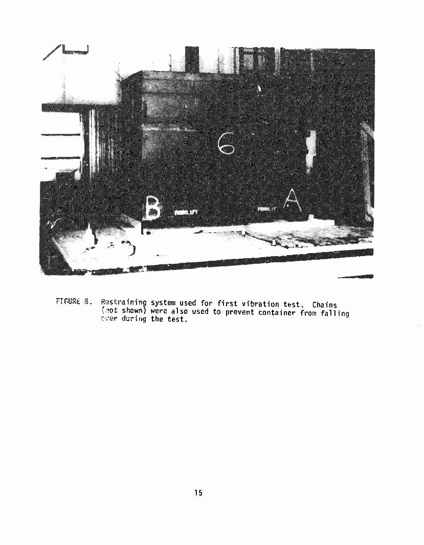
Comments: Although the vibration test was performed according to criteria listed in the test method, the attachment welds of the fork pocket to the container body were subjected to extremely severe loading forces which were excessive and not representative of the intent of the test. These excessive loads were generated primarily by the side to side rocking of the containers. However, since the containers were restrained at the bottom by a 2x4 fence (see Figure 8) and at the top by loose chains which prevented the containers from falling over and the input from the table was 1G, the test was completed.
The end result was failure of the container skin material adjacent to the welds holding the fork pockets onto the containers (see Figures 9 & 10). Excessive wear to the pins and locking angles also occurred (see Figures 11 I 12). It should be noted that, after this vibration test was completed, a method providing a better restraining system that eliminated the rocking motion of the containers was developed. This method of further restraining the containers during testing was acceptable to all concerned (see Figure 13).

Preparations were made to load and use two of the remaining four containers and restart the testing sequence. The manufacturer's representative objected strongly to this approach, stating concern that the first modification which involved removing, changing, and then reattaching the forkwells had embrittled the container skin material during the second welding operation. Lanson offered to supply two new containers at no cost. This proposal was accepted. The two new modified containers arrived on Monday morning, 24 Jan 83. The modificc.tion consisted of welding the forkwell to these in angles (see Figure 14). These two containers, labeled TEST 1 and TEST 2, were loaded and prepared for testing. The test plan was altered from that previously used in two ways. Several of the tests were not repeated due to the results obtained in earlier testing. Also, the sequence was changed to reduce the significance of deformation from drop testing on the vibration test.
Testing began on Wednesday, 26 Jan 83. Following are the tests and results in the sequence performed:
(1) FTMS 101, Method 5009.1 Leaks in Container; Pneumatic Pressure Technique Results: Passed
(2) FTMS 101, Method 5012 Pendulum-Impact Test Results: Passed physical damage criteria
(3) FTMS 101, Method 5019 Vibration (Repetitive Shock) Test Results: Passed physical damage criteria Comments: Successfully restrained rocking of containers
(4) FTMS 101, Method 5007.1 Cornerwise Drop (Rotational) Test Results: Passed physical damage criteria
(5) FTMS 101, Method 5007.1 Free Fall Drop Test Results: Passed physical damage criteria
(6) FTMS 101, Method 5008.1 Edgewise (Rotational) Drop Test Results: Passed physical damage criteria
(7) FTMS 101, Method 5016.1 Superimposed Load Test (Stackability with Dunnage) Results: Passed physical damage criteria
(3) FTMS 101, Method 5009.1 Leaks in Container; Pneumatic Pressure Technique Results: Passed

Following the final leak test, the containers were downloaded and the interiors inspected. With the exception of a narrow strip on the bottom of each container adjacent to the Mylar-coated side, no appreciable damage was noted (see Figure 15).
In view of the added cost associated with the modifications found on these new test containers, two of the original six containers, SN00001 and SN00002, previously untested were loaded. Only one test was conducted to determine the adequacy of the fork pockets. This was the modified version (rocking restraints) of FTMS 101, Method 5019.1, Vibration (Repetitive Shock) Test. The test was conducted on containers 00001 and 00002 exactly as it was for the two previous containers, TEST 1 and TEST 2. These con- tainers also passed the vibration test with no damage. Environmental testing began on 25 Feb 83 with Method 507.1, Humidity; Ammunition and Natural Environment Cycles. In addition to the three-spot humidity indicators present on the containers, two three-spot humidity indicator cards, two irreversible humidity indicator disks, and three clean mild steel coupons were placed in the top of each container (see Figure 16). The lids were replaced and the containers sealed and placed into the humidity test chamber. The chamber malfunctioned on 27 Feb 83. The test unit was removed and the chamber was repaired. Again the containers were dried, sealed, and placed into the test chamber. The test was restarted on 2 Mar 83. The final tests were conducted on 23 Mar 83 and consisted of Method 506.1, Procedure I, Rain of MIL-STD-810C and the four-foot free-fall drop on the most vulnerable area (top corner) in accordance with 49 CFR. The test unit passed both tests. The results of the four-foot drop are represented in Figures 17 & 18.
CONCLUSIONS
The containers passed all of the required tests for qualification. However, three particular deficiencies were discovered during testing.
The most critical problem found concerns the width of the container lids. When two prototype containers are pinned together at the locking angles, their normal shipping and handling configuration, only one of the two lids can be correctly installed (see Figures 19 & 20). In order to install the second lid, the containers must be uncoupled and spread apart, a difficult operation since each container weighs approximately 1200 pounds.
Problems existed with the bolting arrangement used as fasteners on the ends of the lids. When sufficient torque was applied to these bolts to bring the edge of the container lid in contact with the metal bar on the end panel forming the positive stop, a severe bending moment was placed on the bolts. This caused rapid deterioration of threaded surfaces of the bolt and receptacle which results in bolt failure of all four end bolts on the lids. These failures occurred the fourth time the lids were installed during testing and before any environmental tests were conducted.
The container desiccant port cover, a gas-cap type, is very susceptible to permanent damage and loss of seal when impacted. These caps are not repairable and must be replaced when damaged. A more durable desiccant port cover with a replaceable seal was offered for acceptance by Lanson Industries. Qualification testing determined that the replacement cap was equivalent to the original design tested.
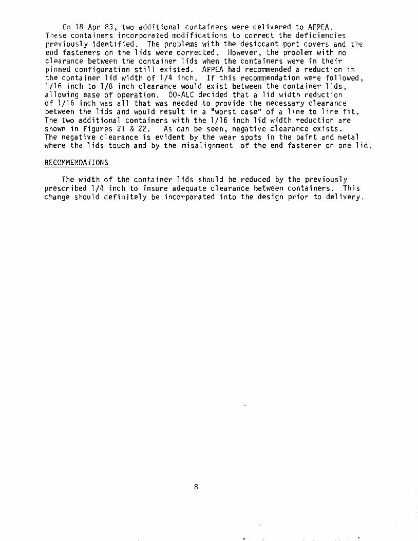
On 18 Apr 83, two additional containers were delivered to AFPEA. These containers incorporated modifications to correct the deficiencies previously identified. The problems with the desiccant port covers and the end fasteners on the lids were corrected. However, the problem with no clearance between the container lids when the containers were in their pinned configuration still existed. AFPEA had recommended a reduction in the container lid width of 1/4 inch. If this recommendation were followed, 1/16 inch to 1/8 inch clearance would exist between the container lids, allowing ease of operation. 00-ALC decided that a lid width reduction of 1/16 inch was all that was needed to provide the necessary clearance between the lids and would result in a "worst case" of a line to line fit. The two additional containers with the 1/16 inch lid width reduction are shown in Figures 21 & 22. As can be seen, negative clearance exists. The negative clearance is evident by the wear spots in the paint and metal where the lids touch and by the misalignment of the end fastener on one lid
RECOMMENDATIONS
The width of the container lids should be reduced by the previously prescribed 1/4 inch to insure adequate clearance between containers. This change should definitely be incorporated into the design prior to delivery.

FIGURE 1. Container in pinned configuration forming test unit.
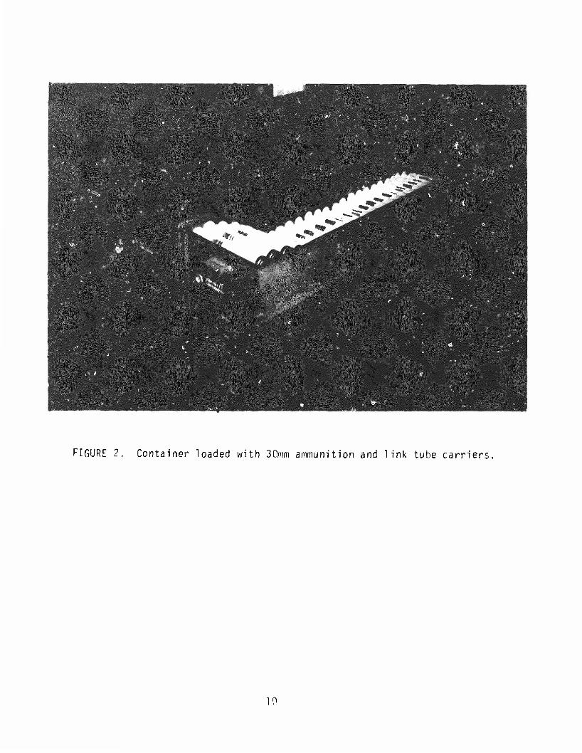
FIGURE 2. Container loaded with 30mm ammunition and link tube carriers.
10

v./'
FIGURE 3. Original containers did not moot the 0 1/1 requirement between forktine open inns for truck compatibility.
; h p pc\ c hand-
in
11

FIGURES 4 15. The first test unit.
m II
12
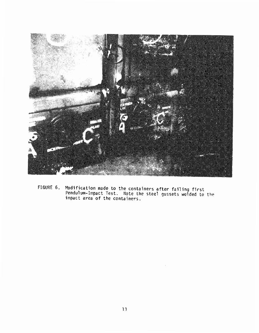
FIGURE 6. Modification made to the containers after failing first Pendulum-Impact Test. Note the steel gussets welded to the impact area of the containers.
13

If \«\ "H
FIGURE 7. The position of the connecting pins was changed from the middle locking angle to the top locking angle due to failure during the first Pendulum-Tmp.-ct Test.
14
/'
FIGURE 3. Restraining system used for first vibration test. Chains (lot shown) were also used to prevent container from fallinq ever during the test.
15

FIGURES 9, 10, 11 & 12. Damage to the containers during the first vibration test resulting in failure.
/ iS.-?fl
VViV.C--'I--';?
••ll llliil^ii •Hill
16

FIGURE 13. Improved restraint test.
system for vibration
17
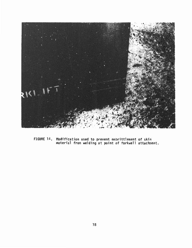
FIGURE 14. Modification used to prevent embrittlement of skin material from welding at point of forkwell attachment.
18

FIGURE 15. Minor scuffing to Mylar-coating inside container vibration testing.
from
19

FIGURE 16. Humidity indicating devices and mild steel coupons placed in the tops of each container prior to environ- mental testing.
20

"•"%
FIGURES 17 & 18. Damage to the containers from four foot free-fall-dron test IAW 49 CFR.
end
s\
Ik
21

,c_ V—,
FIGURES 19 & 2Q, Misaligned lid fasteners.
/
72
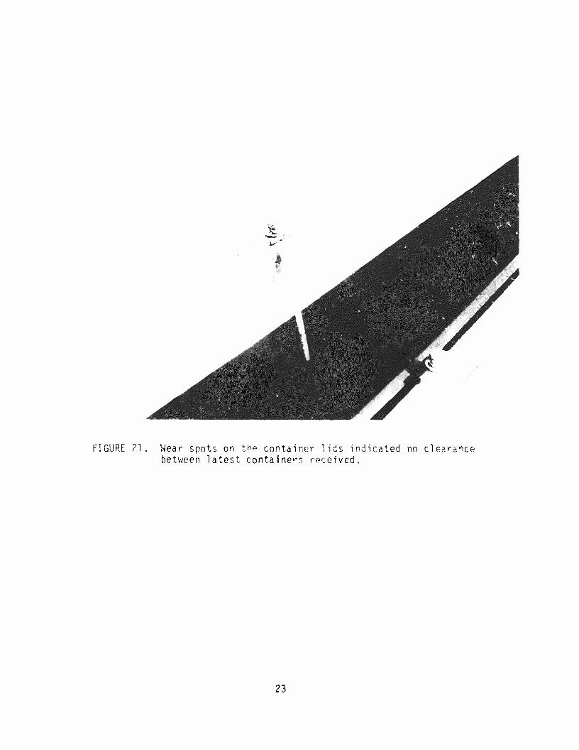
FIGURE ?.] . Wear spots on tnp container lids indicated no clearance between latest containers received.
23

(KM
VI
FIGURE 22, Misalignment of end bolt lid fastener on latest version of container received indicating no clearance between containers. Note the steel gussets welded to threaded bar and container side wall to reduce effect of bending moment on end bolt fasteners.
24

DISTRIBUTION LIST
DTIC/TSR Cameron Station Alexandria ¥A 22314
AFALD/PTP Library MPAFB OH 45433
AFALD/PT/PTPP MPAFB OH 45433
HQ USAF/LETT Kash DC 20330
HQ AFLC/LOW/LOZPP MPAFB OH 45433
OC-ALC/DST Tinker AFB OK 73145
OO-ALC/DST/DSTDM/MAQC/WW Hill AFI UT 84056
SA-ALC/DSP Kelly AFB TX 78241
SM-ALC/DSP McClellan AFB CA 95652
WR-ALC/DSP Robins AFB ISA 31098
ASD/AWl/TAA MPAFB OH 45433
DLSIE USA Logistics Mgmt Cen ATTN: DRXMC-D Ft Lee VA 23801
DARCOM ATTH: SDSTQ-T Tobyhanna PA 18466
COPIES
12
20
COPIES
DESC-T 1507 Wilmington Pike Dayton OH AUU
NAVSUPSYSCMD ATTN: SUP-0321A Hash DC 20376
ADTC/S03P Eglin AFB FL 32542
ASO/TEE/TEP-A 4030 700 Robblns Ave Philadelphia PA 19111
US Army Armament R&D Cmd ATTN: DRDAR-TST-S Dover NJ 07801
GSA Office of Engrg Mgmt Packaging Division Mash DC 20406
TAC/LOWHC Langley AFB VA 23665
AD/YXEP Eglln AFB FL 32542
Lanson Industries, Inc P.O. Drawer 1107 Cullman AL 35055
Aerojet Ordnance Company 9236 E. Hall Road Downey CA 90241
US Army Natick Labs ATTN: DRDNA-EPS Natick MA 01760
5
1
25
UNCLASSIFIED SMUMTY CkASMFICATIOR OF THIS PA@g
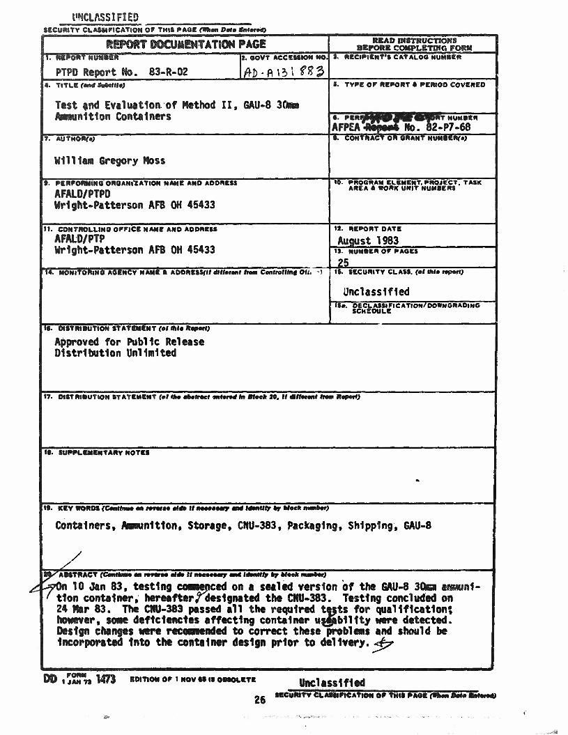
ftgPOftT MCUMBNTATION PAGE irimmrw&amr ———
PTPi Report No. 83-R-02 t. ©OVT Aeesssiots R@.
HE&12 DfSTIWCTIOIfs
4. TITkCf* i. TYPE OF REPORT a PERIOD COVERED
Test and Evaluation of Method II, GAU-8 3Qn inltton Containers
Mil Han 6re§ory *sss
lf^j|**>>lMMifc,^i Wo. B2°P7-§8
tO. PROGRAM ELEMEHT. PROJECT. AREA 6 STORK UNIT NUMBERS
PKRFOfMtNO ©RSARSlAYIOR RAHE AMD ADDRESS
AFALU/PTPD Wright-Patterson AFB 0H 4S433
AND ADDRESS SI. NQOFFICBNJ
AFALD/PTP Mrlght-Pitterson AFB OH 45433
ir-B5Tf©lS¥lWK7w15i'a ADDRESS^ mii*m,t fm» CMMIM* o«~
IS. REPORT DATE
August 1983 13. NUMBER OF PAGES
IS. SECURITY CUASS. (el thle ropertj
Unclassified BECI.ASSIF1CATION/DOWNGRADING
IS. SlSYRISUtlON STATtlSiMT (el me Hep**)
Approval for Public Reims© Distinction Unlimited
17. DISTRIBUTION STATEMENT (el I :20. it
JTARV ROTES
KEY
Containers, Amunltton, Storage, CHU-383, packaging, Shipping, EAU-8
'ABSTRACT
^7S 10 Jan 83, tasting commcM on a sealed version of the SAU-8 3®m en tlon container, hereafter/designated the CMU-383. Testing concluded on 2% Mr 83. The OfU-383 passed all the required tests for qualification*, tmitvir, wm deficiencies affecting container usjiolllty ere detected. Desfg ctanfts wre id to correct these pn is and should he incorporated Into the container design prior to delivery. <4?
inl-
DD i j2T?s M7I ITIO* OP i ROV es is
26 Unclassified
«ey*f^CLMltfi€lfim« ©# THIS PAS*