dss controlling a machine manufacturing havina i. p
TRANSCRIPT

319
DSS CONTROLLING A MACHINE MANUFACTURING
Havina I. P., Lymarenko V. V.
INTRODUCTION A modern machine-building enterprise, based on mechanical machining
of materials, is a complex multi-component system, containing a large number of connections, a great deal of material resources and dataflows. Additionally, as a general rule, such an enterprise is a corporation – a large union of subdivisions. This requires a corporate enterprise control system for timely problem-solving in management1. Creating a control system for such an enterprise is a complicated task and each case has its’ own aspects. The development of modern information technologies provides many opportunities for the perfection of control processes, and the most effective are decision support systems (DSS), developed based on the approach of Artificial Intelligence (AI) – multiagent systems (MAS), which have proven their working capacity and efficiency in real time and consist of groups of various types of agents, and can take upon themselves specific roles in an organizational structure. The unique feature of implementing MAS is the absence of a global control system, data decentralization, calculations are carried
1 Богуслаев А.В. Прогрессивные технологии моделирования, оптимизации и
интеллектуальной автоматизации этапов жизненного цикла авиационных двигателей: монография. Запорожье: Мотор Сич, 2009. 468 с.
Хавина И.П., Дмитриенко В.Д., Верезуб В.Н., Хавин В.Л. Моделирование технологических процессов лезвийной обработки методами искусственного интеллекта: монография. Харьков: НТУ «ХПИ», 2009. 224 с.
Denkena B., Battino A., Woelk P.-O. Intelligent software agents as a basis for collaborative manufacturing systems. Intelligent Production Machines and Systems. First PROMS Virtual Conference 4–15 July 2005, Elsevier, 2005. P. 17-22.
Teti R. Agent-based multiple supplier tool management system. Intelligent Production Machines and Systems, First PROMS Virtual Conference 4–15 July 2005, Elsevier, 2005. P. 579–584.
Cramton P., Shoham Y., Steinberg R. Combinatorial Auctions. MIT Press, 2006. 1179 p. Vorobeychik Y. A game theoretic bidding agent for the ad auction game. Association for the
Advancement of Artificial Intelligence. 2010. P. 6–12. Vokrínek J., Pavlícek D., Šmerák R. Simulation of manufacturing processes using multi-
agent technology. Intelligent Production Machines and Systems, First PROMS Virtual Conference 4–15 July 2005, Elsevier, 2005. P. 461–466.
Vrba P. JAVA-Based Agent platforms evaluation, Holonic and Multi-Agent Systems for Manufacturing. Springer-Verlag Berlin Heidelberg, 2003. P. 47–58.
Khavina I. Multiagent system for the optimal control of a combination of transport robots in a manufacturing technological process. International Conference Telecommunications and Computer Science, TCSET’2016, 23–26 February, 2016, Slavske in Lviv region. P. 468-472.
320
out in asynchronous mode. The individual optimization of each agent’s actions leads to the global optimal system state. This effect appears as a result of agents working together, which is based on the auction principle, with which the optimal solution in the specified situation is identified. Thus, the agent technology is scalable for a wide circle of planning and modeling tasks both for small as well as large enterprises with hundreds of connected devices. The development of such a system is shown in section 1. The MAS system is suggested for planning the capacity load of a machine workshop and takes into consideration the unique features of the machining technological process, including the accumulated tool deterioration and in conditions of the imitation model of manufacturing with the aid of combinational auctions, providing minimal time for manufacturing a product batch.
To ensure the work of the MAS, data on technological processes of cutting materials are necessary and section 2 contains a description method of solving the problem of structural optimization of the technological process of cutting.
One of the important stages of building an effective TP control system is the of the machining process operations’ optimization parameters, thanks to which, using the data obtained on the stage of the TP structural synthesis, the optimal mode of operation of the chosen equipment from chosen criteria’s. Section 3 shows the solution to this problem.
1. Multiagent system for machine workshop work control
A multiagent system of a machine workshop has the following structure , where is a set
of agents; is a set formed at the specific moment of coalition; is the MAS knowledge base. A coalition is regarded as the
temporary union of a certain number of agents with the purpose of achieving a common goal, and their resources remain common. A coalition gives the agents the opportunity to come to an agreement together and create a common plan of action of how to use the common resources and means to coordinately complete all the orders. An agent coalition has the following structure
, where is the coalition’s name; is the set of agents, which are part of the coalition; is the coalition’s goal; is a set of supposed strategies for the coalition’s behavior; KB is the coalition’s knowledge base. Execution of the order plan
is formed by coalitions and their goals are and consist of actions in a certain prioritized
11 1{ , , },{ , , },{ , , }i
k mMAS A A K K KB KB=< > 1{ , , }iA A
1{ , , }kK K
1{ , , }mKB KB
11,{ , , }, ,{ , , }, }n
lK Name A A G St St KB=< > Name1{ , , }nA A G
1{ , , }lSt St
1{ , , , , }m rPZ PZ PZ PZ= 1{ , , , , }m qK K K
1{ , , , , }m qG G G
321
sequence . Plan is the structure
where are the plan’s actions; is the plan’s goal;
are a set of agents carrying out the plan; are the system’s resources. The process of obtaining parts with the help of TP’s based on machine operations with the aid of machining, can be presented in the form of the following stages: 1) forming an application for parts’ production in the form of an order set , sorted by order of their production priority, where is the number of ordered j-type parts; 2) choice of an optimal template for the j-type part; 3) search for the basic TP manufacturer of j-type products in the database, in the form of a set of operations , where is the number of operations in the basic TP for the j-type product; 4) identifying the machine which will carry out the operation in minimal time, considering all the technological limits on the quality of the as-machined service, and considering the part and instrument transportation time; 5) setting and visualizing the schedule of the workshop’s machine inventory.
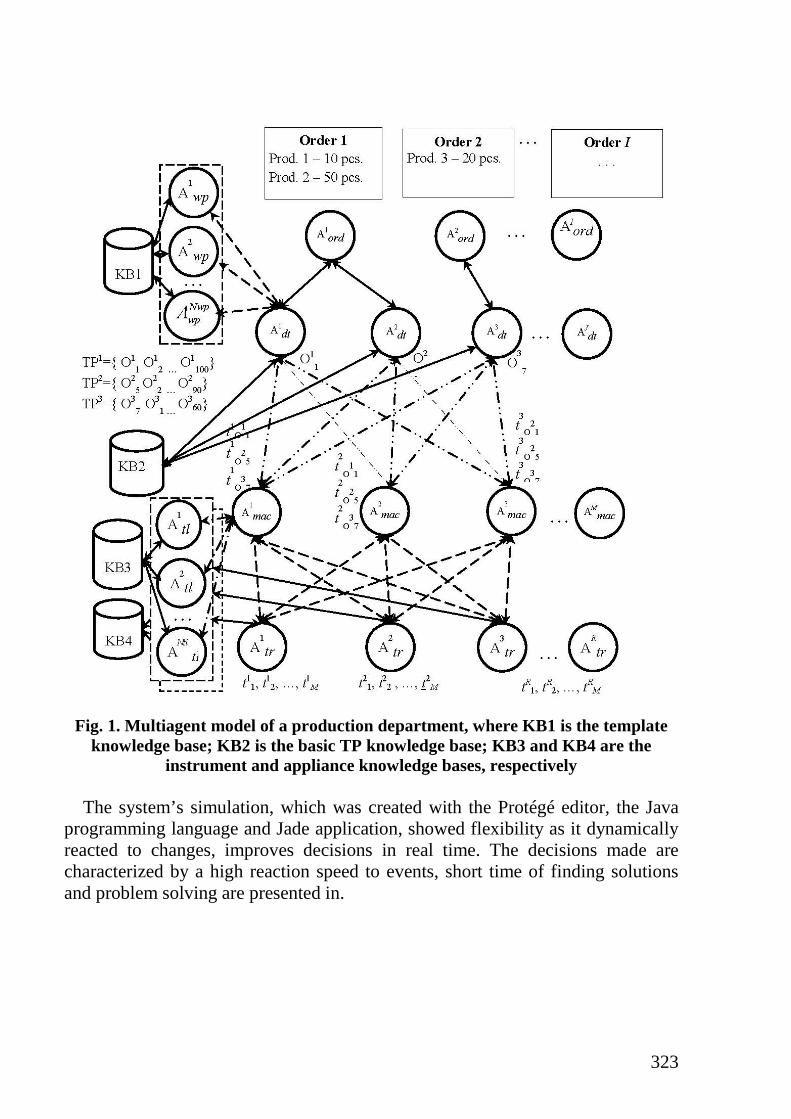
The workshop’s MAS work (fig.1) can be pictured as cooperation of many agents of orders , where I is the number of submitted orders. , which initiate the creation of parts’ agents , where is the number of required j-type parts. send queries to templates’ agents ,
where is the number of types of template for identifying the optimal templates for parts and based on TP database information, identify the basic TP of parts’ production.
Then sequentially send queries to carry out operations from the set of the basic TP to agents of the equipment (machines) , where M is the number of machines, participating in the auction to carry out one TP operation. Every analyzes the query for the operation from and if the machine can execute it and is available (or will be available after a certain amount of time), then agents identify the time for operation execution on the machine. To identify the part, instrument and appliance’s delivery time send their queries for delivery to the transport robots’ agent coalition , where R is the number of robots, participating in the coalitions, and which through the auction for delivery time identify the serviced machine, instrument
1{ , , , , }m pDK DK DK mPZ
1 1 1{ , , , , }, ,{ , , }, ,{ , , }m m p m n m mPZ DK DK DK G AD AD KB ZK ZK=< >
1{ , , , , }m pDK DK DK mG
1{ , , }nAD AD 1{ , , }mZK ZK
1{ , , }jZ Z
jZ
1 2, , , , 1o
jj oТП O O O j j= = ÷
oj
, 1, ,iordA i I= i
ordA, 1, ,j
dtA j J= Jj
dtA , 1, ,nwp wpA n N=
wpN
jdtA
, 1, ,mmacA m M=
mmacA j
dtA
mmacA
mmacA
, 1, ,rtrA r R=
322
and machine for every robot. Each delivery time is calculated as , which answers for the robot control, and the control rules depend on the robot’s brand, its’ work load, displacement speed, presence of manipulators etc.
The data received from the coalition is used during the auction for optimal allocation of all TP operations for all . At the end of TP, the part’s agent makes the decisions about transporting parts to the warehouse or etc.
The objective function of the machines’ agent coalition for executing operations for producing a j-detail, for instance, can be presented as the total time for the production of a part in the form of , where is the
time for operation completion by the equipment m-agent, considering the part, instrument and appliance delivery time; M is the set of machine agents, which make up the coalition and offer to execute the operation for the j-part.
The objective function of template agent coalitions, formed for the production of j-type parts’ batch is given by , , where
is the number of templates, offered by the agent; is the minimal index of economic effectiveness of the j-template, defined as the difference between the production costs of j-type template batches; is a set of template agents, which make up the coalition and offer production from the j-template. An auction, carrying out the greedy algorithm, is implemented to find the optimal template (the auction is marked as on fig. 1).
To find the optimal machine capacity, a combinatorial auction, based on the PAUSE auction, is planned, which uses the distributed algorithm for problem solving; it’s executed in several stages and finds the quasi optimal solution (the auction is marked as on fig.1). These questions will be analyzed in the next publications.
The solution to a transport problem for a transport robot coalition, available in the current moment of time and making up the temporary coalition is shown in 9 and is executed through solving a multicriterial problem of transport robots’ work optimization through forming situational robot coalitions and having these coalitions hold auctions in real time. The auction is marked as on fig.1. The choice of an optimal instrument for operation is likewise carried out based on an auction ( ).
rtrA
mmacA
jdtA
mmacA
minmac mjm M
G t∈
= ⇒∑ mjt
minwp
nwp j j
n NG d f
∈
= ⇒∑ 0 nj jd Z≤ ≤ n
jd
nwpA ijf
wpN
323
Fig. 1. Multiagent model of a production department, where KB1 is the template
knowledge base; KB2 is the basic TP knowledge base; KB3 and KB4 are the instrument and appliance knowledge bases, respectively
The system’s simulation, which was created with the Protégé editor, the Java
programming language and Jade application, showed flexibility as it dynamically reacted to changes, improves decisions in real time. The decisions made are characterized by a high reaction speed to events, short time of finding solutions and problem solving are presented in.
324
2. Method of solving the problem of structural optimization of the technological process of cutting
The tasks of synthesis of the technological process are solved in two stages2. Stage I – structural optimization of the technological process in the form of an optimal sequence of operations of the technological process. Stage II – parametric optimization of the technological process where the search of optimal modes of operation of TP operations takes into account all the limiting factors.
When developing the technological process of cutting, technical and technological parameters of the equipment and tools, the cost of their operation, the wage costs during the operation of this equipment, the efficiency of its use for obtaining the final product with the given properties and characteristics, methods of processing, constraints on the technological opportunity take into account-transition between equipment and operations, etc. The scheme of possible optimization of the technological process shown in fig. 2.
To synthesize the optimal technological process of mechanical processing and to further efficiently manage it, it is necessary to obtain the following sequences and operating modes in which the equipment will be used with maximum efficiency and minimum processing cost.
In general, the statement of the problem of synthesis of the optimal technological process is as follows. The choice criteria for optimization for the technological process of machining K usually used either the co-cost of the product CB, or the efficiency of the P. The optimal technological process of the TO is the following where M – the set of possible variants of the technological process. The essence of search engine optimization in finding the best of the technological process, which holds inequalities:
where i – number of variants of technological processes. Tasks of stage I – definition of structural optimization TP are often solved by
three basic methods: the method of analogies, the method of analysis and the method of synthesis. The method of synthesis is based on the consistent hierarchical synthesis of the technological process, consisting of the synthesis of a series of technological operations and their distribution in time. For this, the item is divided into elementary surfaces, the intermediate states for determining the intermediate states are determined, and the methods of their processing are
2 Rao V. Advanced Modeling and Optimization of Manufacturing Processes. International
Research and Development. Springer-Verlag, London Limited, 2011. Haykin S. Neural Networks and Learning Machines. 3rd ed. Pearson Education, Upper
Saddle River, New Jersey. 2009, 907 р.
( ) min ( ),В О BС Т C K= ( ) max ( ),ОP Т P K= ,ОТ М∈
1 1( ) ( ), ( ) ( ),В i В i i iС К С К P К P К+ +> <

325
selected. In this case, the dimensional bonds of the elements of the component are taken into account and the synthesis of the bases and operations structures is performed. The method is devoid of the disadvantages of the previous two methods, because: for its work it is not necessary to have knowledge bases of similar technological processes; the synthesis of TP turns out to be a completely new technological process, which is based on synthesized precisely for it operations, and not on unified standard solutions that by default assume averaging; the synthesis is performed taking into account the optimization goals relevant for this TP. In the work for the solution a method artificial intelligence methods, namely, production rules, implemented using the language of logical programming, was used. In fig. 3 shows a tree of synthesis of optimal TP production of products by mechanical cutting, consisting of 7 levels.
Fig. 2. Scheme of optimization of the technological process of machining
Beginning
Did you get the optimum product?
Formation of processing route and technological maps
End
Structural optimization
Parametric optimization
Analysis of input data
Calculation of parameters for the selected structure
No
Yes

326
Fig. 3. Tree of synthesis of optimum TP making of products by means
of mechanized cutting
1 Selection of optiongetting the workpiece
A set of possible options for billets
A set of possible sizes of billets
2 Selection of the necessary technological transitions
A set of possible variants of technological transitions
A set of possible variants of technological transition
5 Selection of necessary adaptations and methods of installation of the workpiece
A variety of possible variants of gadgets
A set of possible installation options in each appliance
3 Selection of the right equipment
A set of possible variants of the necessary equipment
A set of specific machine tools of the type required
4 Selection of the right tool
A set of possible types of instrument
A set of possible modifications of the tool type
6 Selection of lubricating and cooling technological environment
A variety of possible variants of lubricating and cooling technological environments
A variety of possible types of lubricating and cooling technological environments
Formation of a technological map7
327
Level from fig. 3: 1 – selection of workpiece; 2 – selection of technological transitions; 3 – equipment selection; 4 – selection of tools; 5 – selection of adaptations and methods of installation of the workpiece; 6 – selection of lubricating and cooling technological environment; 7 – formation of technolo- gical map. At 1, 5, 6 levels one solution is obtained, and at 2, 3, 4 levels– several alternative solutions.
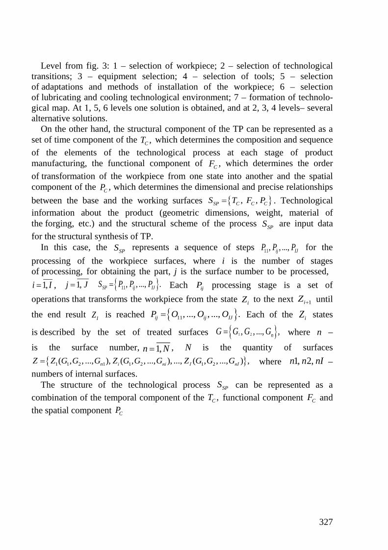
On the other hand, the structural component of the TP can be represented as a set of time component of the which determines the composition and sequence of the elements of the technological process at each stage of product manufacturing, the functional component of , which determines the order of transformation of the workpiece from one state into another and the spatial component of the , which determines the dimensional and precise relationships between the base and the working surfaces . Technological information about the product (geometric dimensions, weight, material of the forging, etc.) and the structural scheme of the process are input data for the structural synthesis of TP.
In this case, the represents a sequence of steps for the processing of the workpiece surfaces, where i is the number of stages of processing, for obtaining the part, j is the surface number to be processed,
, Each processing stage is a set of operations that transforms the workpiece from the state to the next until
the end result is reached Each of the states
is described by the set of treated surfaces where n –
is the surface number, , N is the quantity of surfaces where –
numbers of internal surfaces. The structure of the technological process can be represented as a
combination of the temporal component of the functional component and the spatial component
,CT
CF
CP{ }, ,SP C C CS T F P=
SPS
SPS 11, , ...,ij IJP P P
1,i I= 1,j J= { }11, , ..., .SP ij IJS P P P= ijP
iZ 1iZ +
IZ { }11, ..., , ..., .ij ij IJP O O O= iZ
{ }1 2, , ..., ,nG G G G=
1,n N={ }1 1 2 1 1 2 1 2( , , ..., ), ( , , ..., ), ..., ( , , ..., ) ,n і nі I nIZ Z G G G Z G G G Z G G G= 1, 2,n n nI
SPS,CT CF
CP
328
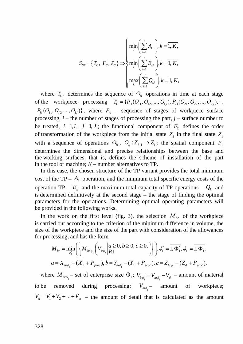
where determines the sequence of operations in time at each stage
of the workpiece processing , where Рij – sequence of stages of workpiece surface
processing, i – the number of stages of processing the part, j – surface number to be treated, ; the functional component of defines the order of transformation of the workpiece from the initial state in the final state with a sequence of operations , ; the spatial component determines the dimensional and precise relationships between the base and the working surfaces, that is, defines the scheme of installation of the part in the tool or machine; K – number alternatives to TP.
In this case, the chosen structure of the TP variant provides the total minimum cost of the TP – operation, and the minimum total specific energy costs of the operation TP – and the maximum total capacity of TP operations – and is determined definitively at the second stage – the stage of finding the optimal parameters for the operations. Determining optimal operating parameters will be provided in the following works.
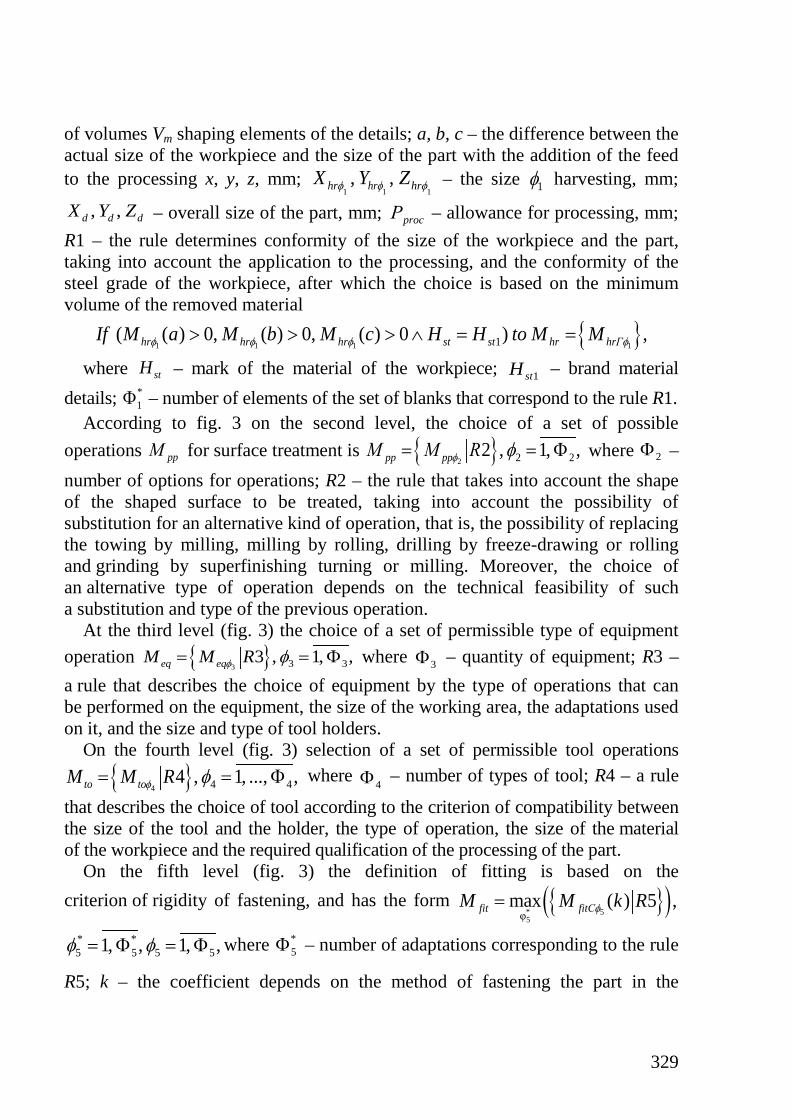
In the work on the first level (fig. 3), the selection of the workpiece is carried out according to the criterion of the minimum difference in volume, the size of the workpiece and the size of the part with consideration of the allowances for processing, and has the form
where – set of enterprise size ; – amount of material
to be removed during processing; – amount of workpiece;
– the amount of detail that is calculated as the amount
{ }
1
1
1
min , 1, ,
, , min , 1, ,
max , 1, ,
I
kіk i
I
SP C C C kіk i
I
kіk i
A k K
S T F P E k K
Q k K
=
=
=
=
= ⇒ =
=
∑
∑
∑,CT ijO
11 11 12 1 21 21 22 2{ ( , , ..., ), ( , , ..., ),С j jT P О О О P О О О= ...,
1 2( , , ..., )}IJ I I IJP О О О
1, ,i I= 1,j J= CF
1Z 1ZijO 1:ij i iO Z Z− → CP
kA
kE kQ
hrМ
* 1 11
* *φ Рφ 1 1 1 1φ
0, 0, 0,min , 1, , 1, ,1hr hra b cM M V R φ φ ≥ ≥ ≥ = = Φ = Φ
1 1 1( ), ( ), ( ),hr d proc hr d proc hr d proca X Х Р b Y Y Р c Z Z Рφ φ φ= − + = − + = − +
1φhrM 1Φ1 1Рφ hr dV V Vφ= −
1hrV φ
1 2 ...d mV V V V= + + +
329
of volumes Vm shaping elements of the details; a, b, c – the difference between the actual size of the workpiece and the size of the part with the addition of the feed to the processing x, y, z, mm; – the size harvesting, mm;
– overall size of the part, mm; – allowance for processing, mm; R1 – the rule determines conformity of the size of the workpiece and the part, taking into account the application to the processing, and the conformity of the steel grade of the workpiece, after which the choice is based on the minimum volume of the removed material
where – mark of the material of the workpiece; – brand material
details; – number of elements of the set of blanks that correspond to the rule R1. According to fig. 3 on the second level, the choice of a set of possible
operations for surface treatment is where – number of options for operations; R2 – the rule that takes into account the shape of the shaped surface to be treated, taking into account the possibility of substitution for an alternative kind of operation, that is, the possibility of replacing the towing by milling, milling by rolling, drilling by freeze-drawing or rolling and grinding by superfinishing turning or milling. Moreover, the choice of an alternative type of operation depends on the technical feasibility of such a substitution and type of the previous operation.
At the third level (fig. 3) the choice of a set of permissible type of equipment operation where – quantity of equipment; R3 – a rule that describes the choice of equipment by the type of operations that can be performed on the equipment, the size of the working area, the adaptations used on it, and the size and type of tool holders.
On the fourth level (fig. 3) selection of a set of permissible tool operations where – number of types of tool; R4 – a rule
that describes the choice of tool according to the criterion of compatibility between the size of the tool and the holder, the type of operation, the size of the material of the workpiece and the required qualification of the processing of the part.
On the fifth level (fig. 3) the definition of fitting is based on the criterion of rigidity of fastening, and has the form
where – number of adaptations corresponding to the rule
R5; k – the coefficient depends on the method of fastening the part in the
1,hrX φ 1
,hrY φ 1hrZ φ 1φ, ,d d dX Y Z procР
{ }1 1 1 11( ( ) 0, ( ) 0, ( ) 0 ) ,hr hr hr st st hr hrГIf M a M b M c H H to M Mφ φ φ φ> > > ∧ = =
stH 1stH*1Φ
ppМ { }2 2 22 , 1, ,pp ppМ M Rφ φ= = Φ 2Φ
{ }3 3 33 , 1, ,eq eqM M Rφ φ= = Φ 3Φ
{ }4 4 44 , 1, ..., ,to toM M Rφ φ= = Φ 4Φ
{ }( )* 55φ
max ( ) 5 ,fit fitСM M k Rφ=
* *5 5 5 51, , 1, ,φ φ= Φ = Φ *
5Φ
330
cartridge; R5 – a rule that defines the fitting according to the rigidity of the fixing and the linear dimension of the part that can be fitted to it; – number of possible variants of fitting.
On the sixth level (fig. 3) the definition of ICTE is based on the criterion of minimum value where
– the number of ICTE elements that match the rule R6; – number of possible options ICTE; – cost ICTE; R6 – a rule that defines ICTE's choice for the minimum cost criterion, the possible use on the equipment chosen for the operation and with the required material for the workpiece.
At the seventh level (fig. 3) several variants of the route map of the technological process of making the product from the metal are made by cutting operations.
With this approach, the task has a multivariate solution, so the final decision on determining the necessary equipment and instrument will be obtained after determining the optimal operating parameters, according to the criteria
where – cost of operation on r-th equipment; R – quantity of equipment; – specific energy consumption on r-th equipment; – performance of opera-
tion on r-th equipment; – cost of operation on p-th instrument; P – amount of tool; – specific power consumption on p-th instrument; – performance of the p-th instrument operation.
This allowed to determine the composition and sequence of elements of the TP at each stage of product manufacturing, the order of transformation of the workpiece from one state to another and the determined dimensional and precise relationships between the base and working surfaces were determined.
For the functioning of the system, with the production rules, a knowledge base was created that includes data on equipment parameters, workpieces, tools, IOTS, accumulated knowledge of cutting theory, experience of expert technicians, regulatory requirements, etc., using logical programming methods. For realization of the system the Visual Prolog was used.
5Φ
{ }( )* 66
* *6 6 6 6φ
min ( ) 6 , 1, , 1, ,ICTE ICTE ICTEМ М P Rφ φ φ= = Φ = Φ
*6Φ 6Φ
ISTEP
equipmentМ toolМ
t pr
equipment r p
r p
min( ( )), 1, ,min( ( )), 1, ,
min( ( )), 1, , min( ( )), 1, ,
max( ( )), 1, , max( ( )), 1, ,
p or eq pr
r eq tool p tor p
r eq p tor p
A М p PA M r R
М E M r R М E М p P
Q M r R Q М p P
== ⇒ = ⇒ =
= =
rA
rE rQ
pAЭ p рQ

331
3. Operational parametrs optimization of TP machining considering accumulated wear
One of the important stages of building an effective TP control system is the II stage of the machining process operations’ optimization, thanks to which, using the data obtained on the stage of the TP structural synthesis, the mode of operation of the chosen equipment, which provides its’ optimal work from the position of the chosen criteria3. The task of parametrical optimization of the machining process is a multicriterial multiparametrical optimization problem (MOP). This is due to the fact that criteria of TP optimization are often various contradictory criteria such as performance (Q), prime cost (А), quality of the finished surface etc.
Different approaches and methods are applied in solving MOP: the generalized criteria method (additive criteria, multiplicative criteria); the “convolution” method (method of stepwise concession, main criteria method); the special method of solving multicriterial problems (lexicographical method, search of a Paretooptimal solution).
To obtain numerous MOP TP solutions, algorithms in which Pareto’s domination concept is explicitly used, for example, VEGA, FFGA, NPGA, SPEA4.
The value of the instrument’s accumulated wear ( ) has the biggest effect on the change of the machining process’ output parameters. This is because with the same input operational parameters, the level of machining force, the finish of the processed surface, the temperature in the machining zone, dimensional accuracy of the acquired part, etc., all depend on the level of wear5. The innovation in this approach is the consideration of the value of the instrument’s present accumulated wear, which allows receiving a more adequate mathematical model physically, and thus, a physically more realistic optimal MOP solution.
When posing problems of machining processes’ parametrical optimization, 4 objective functions are examined, based on the example of the clean machining
3 Zitzler E., Deb K., Thiele L. Comparison of Multiobjective Evolutionary Algorithms:
Empirical Results. Massachusetts Institute of Technology. Evolutionary Computation. 2000. № 8 (2). P. 173–195.
4 Zitzler E., Deb K., Thiele L. Comparison of Multiobjective Evolutionary Algorithms: Empirical Results. Massachusetts Institute of Technology. Evolutionary Computation. 2000. № 8 (2). P. 173–195.
5 Албагачиев А.Ю., Султан-Заде Н.М. Теоретические основы металлообработки в машиностроении. Старый Оскол, ТНТ, 2014. 552 с.
Ozel T., Hsu T.-K., Zeren E. Effects of cutting edge geometry, workpiece hardness, feed rate and cutting speed on surface roughness and forces in finish turning. International journal of Advanced Manufacturing Technology. 2005. № 25. P. 262–269.
Zh
332
operation: operation prime cost A, energy demands Ez, dimensional accuracy , activity throughput Q and 10 limitations: in the electric motor power of the main motion drive machine Ndv; in the minimal and maximum machining speed V; in the minimal and maximum feed rate S; in the durability of the machining instrument (by maximum strain ); in the stability of the machining instrument (deflection fi); in the template stability (deflection fz); in the stability of the longitudinal feed mechanism of the machine (maximum force Fxd); in the finish of the completed surface Ra.
The optimal solution is identified through the process of minimization (maximization) of the respective objective functions or their combinations through the search of an optimal combination of variate parameters of feedrate S and machining speed V within the margins of the operation of processing every consecutive part.
The objective functions examined in the paper are as follows6:
where is the template length, mm; is the employee’s salary per minute,
UAH/min; is the expenses on machine service, UAH/min; e is the instrument
cost, UAH; − is the time of effective instrument service (effective durability period), min; is the cost of one kWatt/hour electricity, UAH; is the tangential machining force, N; is the machine’s efficiency; is the machine’s radial force, N; is the coefficient, which depends on the method of template securing; is the template’s Young’s modulus, MPa; is the moment of inertia of the template’s cross section, mm4; t is the machining depth, mm; is the allowance, mm.
The limits in solving MOP are presented in the functions:
6 Ящерицин П.И., Фельдштейн Ю.Е., Корниевич М.А. Теория обработки. Минск:
«Новое Знание», 2006. 512 с.
Σ∆
maxσ
exp 4 4min min,6 10 6 10
z e Z zrab
ef st st
l e q F V F VA a a , EzS Т η η
= + + + ⇒ = ⇒ ⋅ ⋅ 3
З
min maxy zΣ
z z z
F l StΔ ,Q ,k E I l
= ⇒ = ⇒∆
zl raba
expaefТ
eqzF
stη yF
zk
zE zI
∆
[ ]min max min max max4
33
max
60 10
3
z i zpzdv dp i
st i
y zz ii id z zd x xd a z a
i i z z
F l kF VN N ,V V V , S S S ,σ σ ,η W
F lF lf f , f f , F F , R (V,S,t,h ) R ,E I kE I
= ≤ ≤ ≤ ≤ ≤ = ≤⋅
= ≤ = ≤ ≤ ≤
333
where: Ndp is the machine electric motor’s documented maximum consumption capacity, kWatt; Vmin is the minimal allowed machining velocity, m/min; Vmax is the maximum allowed machining velocity, m/min; Smin is the minimum allowed machine feed rate, mm/min; Smax is the maximum allowed machine feed rate, mm/min; kzp is the assurance factor; Wi is the Z-modulus of the tool rest holder, mm3; is the working pressure of the tool rest holder, MPa; li is the tool rest holder’s length, mm; Ei is the elasticity of the tool rest holder material, N/mm2; Ii is the second area moment of the tool rest holder, mm4; fid is the allowed flexibility of the tool rest holder, mm; fzd is the allowed flexibility for the template, mm; Fx is the axial force, N; Rαmax is the maximum allowed finish of the processed surface, mkm.
It’s important to note that the working (output) parameters of the processing process, such as the time of effective service of the instrument Тef, cutting force Fz, Fy, finish of the processed surface Ra etc. depend on variate parameters S and V and the accumulated wear of the back surface of the machining instrument hZ. In its’ turn, the change of wear for the time of processing one template is defined by the level of the wear accumulated earlier and operational parameters S and V. Separate functional dependencies for output parameters are described analytically, and in most practical cases, experimental-analytical or simply experimental functions are used7.
The obtained model of the sharpening process has the 41 input parameters, 80 process parameters are calculated. As mentioned earlier, one of the problems, which appear when solving the given problem, is that for several parameters in the mathematical model, the function, which describes them with a high level of accuracy, is hard to formalize, or the applied functions contain empirical coefficients, obtained through a large number of experiments. Thus, to obtain a set of functions, an ANN perceptron with back propagation of error was employed. Data from was approximated with the help of ANN to define hZ and Ra.
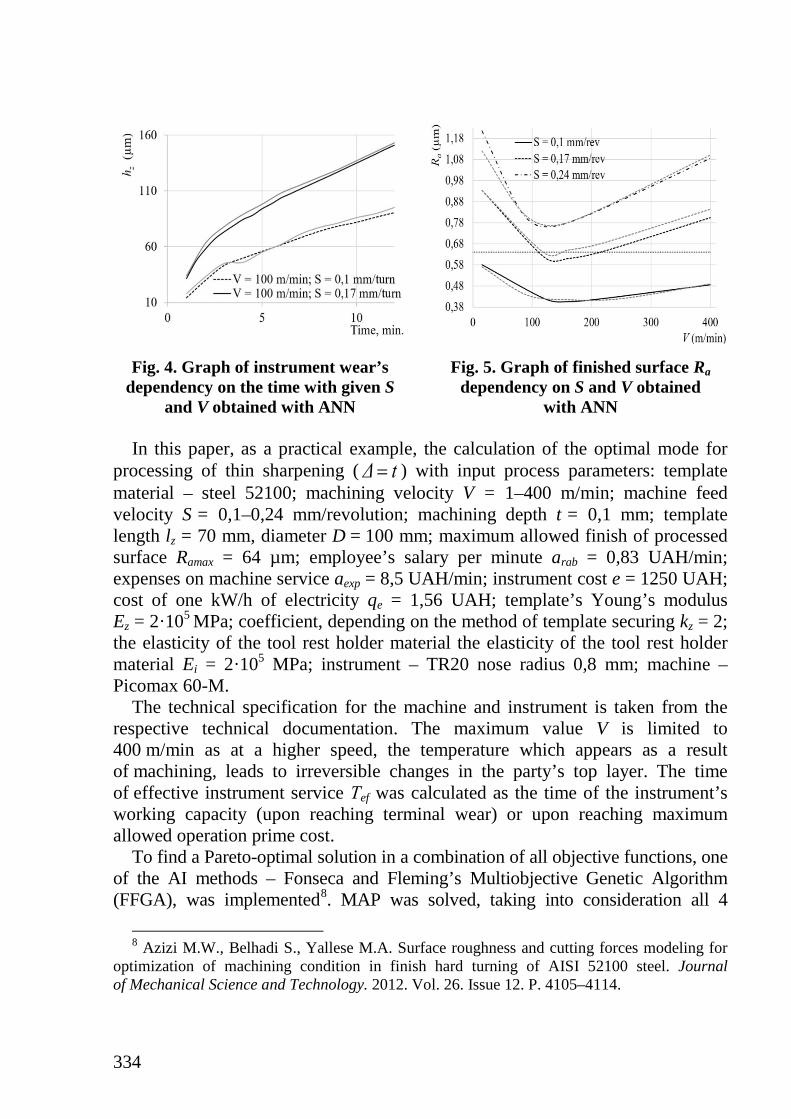
The calculation of the optimal mode for a clean sharpening operation is given as an example for “Filter housing”. As an example, fig. 4–5 uses the approximation results using ANN experimental data from to obtain formulas and with a fixed machining depth. When approximating data with the help of ANN, it was possible to obtain a maximum operational margin of 2–3%.
7 Fonseca C.M. Multiobjective optimization and multiple constraint handling with
evolutionary algorithms. IEEE Transactions on Systems, Man, and Cybernetics, Part A: Systems and Humans. 1998. № 28. P. 26–37.
Song W. Development of predictive force models for classical orthogonal and oblique cutting and turning operations incorporating tool flank wear effects. PhD, Queensland University of Technology, 2006. 208 р.
[ ]iσ
Zh∆
( , , )Z Zh h S V t= ( , )a aR R S V=
334
Fig. 4. Graph of instrument wear’s
dependency on the time with given S and V obtained with ANN
Fig. 5. Graph of finished surface Ra dependency on S and V obtained
with ANN In this paper, as a practical example, the calculation of the optimal mode for
processing of thin sharpening ( ) with input process parameters: template material – steel 52100; machining velocity V = 1–400 m/min; machine feed velocity S = 0,1–0,24 mm/revolution; machining depth t = 0,1 mm; template length lz = 70 mm, diameter D = 100 mm; maximum allowed finish of processed surface Ramax = 64 µm; employee’s salary per minute arab = 0,83 UAH/min; expenses on machine service aexp = 8,5 UAH/min; instrument cost e = 1250 UAH; cost of one kW/h of electricity qe = 1,56 UAH; template’s Young’s modulus Ez = 2·105 MPa; coefficient, depending on the method of template securing kz = 2; the elasticity of the tool rest holder material the elasticity of the tool rest holder material Ei = 2·105 MPa; instrument – TR20 nose radius 0,8 mm; machine – Picomax 60-M.
The technical specification for the machine and instrument is taken from the respective technical documentation. The maximum value V is limited to 400 m/min as at a higher speed, the temperature which appears as a result of machining, leads to irreversible changes in the party’s top layer. The time of effective instrument service Тef was calculated as the time of the instrument’s working capacity (upon reaching terminal wear) or upon reaching maximum allowed operation prime cost.
To find a Pareto-optimal solution in a combination of all objective functions, one of the AI methods – Fonseca and Fleming’s Multiobjective Genetic Algorithm (FFGA), was implemented8. MAP was solved, taking into consideration all 4
8 Azizi M.W., Belhadi S., Yallese M.A. Surface roughness and cutting forces modeling for
optimization of machining condition in finish hard turning of AISI 52100 steel. Journal of Mechanical Science and Technology. 2012. Vol. 26. Issue 12. P. 4105–4114.
Δ t=
335
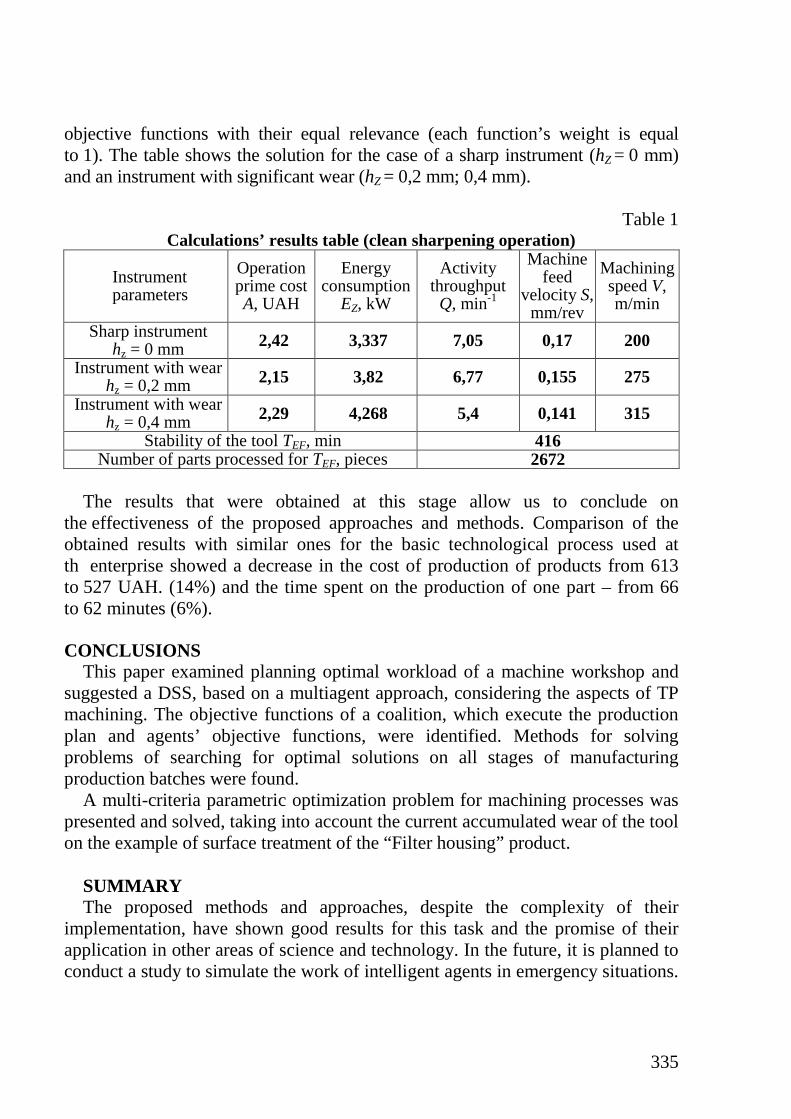
objective functions with their equal relevance (each function’s weight is equal to 1). The table shows the solution for the case of a sharp instrument (hZ = 0 mm) and an instrument with significant wear (hZ = 0,2 mm; 0,4 mm).
Table 1
Calculations’ results table (clean sharpening operation)
Instrument parameters
Operation prime cost A, UAH
Energy consumption
EZ, kW
Activity throughput
Q, min-1
Machine feed
velocity S, mm/rev
Machining speed V, m/min
Sharp instrument hz = 0 mm 2,42 3,337 7,05 0,17 200
Instrument with wear hz = 0,2 mm 2,15 3,82 6,77 0,155 275
Instrument with wear hz = 0,4 mm 2,29 4,268 5,4 0,141 315
Stability of the tool TEF, min 416 Number of parts processed for TEF, pieces 2672
The results that were obtained at this stage allow us to conclude on
the effectiveness of the proposed approaches and methods. Comparison of the obtained results with similar ones for the basic technological process used at th enterprise showed a decrease in the cost of production of products from 613 to 527 UAH. (14%) and the time spent on the production of one part – from 66 to 62 minutes (6%).
CONCLUSIONS
This paper examined planning optimal workload of a machine workshop and suggested a DSS, based on a multiagent approach, considering the aspects of TP machining. The objective functions of a coalition, which execute the production plan and agents’ objective functions, were identified. Methods for solving problems of searching for optimal solutions on all stages of manufacturing production batches were found.
A multi-criteria parametric optimization problem for machining processes was presented and solved, taking into account the current accumulated wear of the tool on the example of surface treatment of the “Filter housing” product.
SUMMARY The proposed methods and approaches, despite the complexity of their
implementation, have shown good results for this task and the promise of their application in other areas of science and technology. In the future, it is planned to conduct a study to simulate the work of intelligent agents in emergency situations.
336
In the future, it is planned to conduct a study to simulate the work of intelligent agents in emergency situations.
REFERENCES 1. Богуслаев А.В. Прогрессивные технологии моделирования, оптими-
зации и интеллектуальной автоматизации этапов жизненного цикла авиационных двигателей: монография. Запорожье: Мотор Сич, 2009. 468 с.
2. Хавина И.П., Дмитриенко В.Д., Верезуб В.Н., Хавин В.Л. Модели- рование технологических процессов лезвийной обработки методами искусственного интеллекта: монография. Харьков: НТУ «ХПИ», 2009. 224 с.
3. Denkena B., Battino A., Woelk P.-O. Intelligent software agents as a basis for collaborative manufacturing systems. Intelligent Production Machines and Systems. First PROMS Virtual Conference 4–15 July 2005, Elsevier, 2005. P. 17–22.
4. Teti R. Agent-based multiple supplier tool management system. Intelligent Production Machines and Systems, First PROMS Virtual Conference 4–15 July 2005, Elsevier, 2005. P. 579–584.
5. Cramton P., Shoham Y., Steinberg R. Combinatorial Auctions. MIT Press, 2006. 1179 p.
6 .Vorobeychik Y. A game theoretic bidding agent for the ad auction game. Association for the Advancement of Artificial Intelligence, 2010. P. 6–12.
7. Vokrínek J., Pavlícek D., Šmerák R. Simulation of manufacturing processes using multi-agent technology. Intelligent Production Machines and Systems, First PROMS Virtual Conference 4–15 July 2005, Elsevier, 2005. P. 461–466.
8. Vrba P. JAVA-Based Agent platforms evaluation, Holonic and Multi-Agent Systems for Manufacturing. Springer-Verlag Berlin Heidelberg, 2003. P. 47–58.
9. Khavina I. Multiagent system for the optimal control of a combination of transport robots in a manufacturing technological process. International Conference Telecommunications and Computer Science, TCSET’2016, 23–26 February, 2016, Slavske in Lviv region. P. 468–472.
10. Rao V. Advanced Modeling and Optimization of Manufacturing Processes. International Research and Development. Springer-Verlag, London Limited, 2011.
11. Haykin S. Neural Networks and Learning Machines. 3rd ed. Pearson Education, Upper Saddle River, New Jersey. 2009, 907 р.
12. Zitzler E., Deb K., Thiele L. Comparison of Multiobjective Evolutionary Algorithms: Empirical Results. Massachusetts Institute of Technology. Evolutionary Computation. 2000. № 8 (2). P. 173–195.
13. Албагачиев А.Ю., Султан-Заде Н.М. Теоретические основы металло- обработки в машиностроении. Старый Оскол, ТНТ, 2014. 552 с.
337
14. Ozel T., Hsu T.-K., Zeren E. Effects of cutting edge geometry, workpiece hardness, feed rate and cutting speed on surface roughness and forces in finish turning. International journal of Advanced Manufacturing Technology. 2005. №25. P. 262–269.
15. Ящерицин П.И., Фельдштейн Ю.Е., Корниевич М.А. Теория обработки. Минск: «Новое Знание», 2006. 512 с.
16. Fonseca C.M. Multiobjective optimization and multiple constraint handling with evolutionary algorithms. IEEE Transactions on Systems, Man, and Cybernetics, Part A: Systems and Humans. 1998. № 28. P. 26–37.
17. Song W. Development of predictive force models for classical orthogonal and oblique cutting and turning operations incorporating tool flank wear effects. PhD, Queensland University of Technology, 2006. 208 р.
18. Azizi M.W., Belhadi S., Yallese M.A. Surface roughness and cutting forces modeling for optimization of machining condition in finish hard turning of AISI 52100 steel. Journal of Mechanical Science and Technology. 2012. Vol. 26. Issue 12. P. 4105–4114.
19. Azizi M.W., Belhadi S., Yallese M.A. Surface roughness and cutting forces modeling for optimization of machining condition in finish hard turning of AISI 52100 steel. Journal of Mechanical Science and Technology. 2012. Vol. 26. Issue 12. P. 4105–4114.
Information about authors:
Khavina I. P., Candidate of Technical Sciences,
Associate Professor of Chair of Computing and Programming National Technical University “Kharkiv Polytechnic Institute”
2, Kyrpychova str., Kharkiv, 61002, Ukraine
Lymarenko V. V., Candidate of Technical Sciences,
Assistant Professor of Chair of Computing and Programming National Technical University “Kharkiv Polytechnic Institute”
2, Kyrpychova str., Kharkiv, 61002, Ukraine