dss-24 auto negotiation switch user’s...
TRANSCRIPT

i
DSS-24 Auto Negotiation Switch User’sGuide
Rev. 01 (March, 1999)
651DS24..K15

ii
Copyright © 1999 by D-Link Systems, Inc. All rights reserved.D-Link Limited Warranty
Hardware:
D-Link warrants its hardware products to be free from defects in workmanship and materials, under normal use and service, for thefollowing periods measured from date of purchase from D-Link or its authorized Reseller:
Product Type Warranty PeriodComplete Products One yearSpare parts and spare kits 90 days
Your dealer, or your nearest D-Link office, can advise whether a longer period of warranty applies to your purchase, and if so, can provideyou a separate certificate of supplemental warranty.
The one-year period of warranty on complete products (or such longer period of warranty as may be offered as to your purchase) applieson condition that the product’s Registration Card is filled out and returned to a D-Link office within ninety (90) days of purchase. A list of D-Link offices is provided at the back of this manual, together with a copy of the Registration Card. Failing such timely registration ofpurchase, the warranty period shall be limited to ninety (90) days.
If the product proves defective within the applicable warranty period, D-Link will provide repair or replacement of the product. D-Link shallhave the sole discretion whether to repair or replace, and replacement product may be new or reconditioned. Replacement product shall beof equivalent or better specifications, relative to the defective product, but need not be identical. Any product or part repaired by D-Linkpursuant to this warranty shall have a warranty period of not less than 90 days, from date of such repair, irrespective of any earlierexpiration of original warranty period. When D-Link provides replacement, then the defective product becomes the property of D-Link.
Warranty service may be obtained by contacting a D-Link office within the applicable warranty period, and requesting a Return MaterialAuthorization (RMA) number. If a Registration Card for the product in question has not been returned to D-Link, then a proof of purchase(such as a copy of the dated purchase invoice) must be provided. If handling of warranty correction is required under specialcircumstances, you may request special procedure at the time of requesting an RMA number.
After an RMA number is issued, the defective product must be packaged securely in the original or other suitable shipping package toensure that it will not be damaged in transit, and the RMA number must be prominently marked on the outside of the package. The packagemust be mailed or otherwise shipped to D-Link with all costs of mailing/shipping/insurance prepaid: D-Link will ordinarily reimburse formailing/shipping/insurance expenses incurred for return of defective product in accordance with this warranty. D-Link shall never beresponsible for any software, firmware, information, data contained in, stored on or integrated with any product returned to D-Link pursuantto this warranty.
Any package returned to D-Link without an RMA number will be rejected and shipped back to you at your expense, and D-Link reserves theright in such case to levy a reasonable handling charge in addition to mailing or shipping costs.
Software:
Warranty service for software products may be obtained by contacting a D-Link office within the applicable warrantyperiod. A list of D-Link offices is provided at the back of this manual, together with a copy of the Registration Card. If aRegistration Card for the product in question has not been returned to a D-Link office, then a proof of purchase (such asthe dated purchase invoice) must be provided when requesting warranty service. The term “purchase” in this softwarewarranty refers to the purchase transaction and resulting license to use such software.
D-Link warrants that its software products will perform in substantial conformance with the applicable productdocumentation provided by D-Link with such software product, for a period of ninety (90) days from the date of purchasefrom D-Link or its Authorized Reseller. D-Link warrants the magnetic media, on which D-Link provides its softwareproduct, against failure during the same warranty period. This warranty applies to purchased software, and to replacementsoftware provided by D-Link pursuant to this warranty, but shall not apply to any update or replacement which may beprovided for download via the Internet, or to any update which may otherwise be provided free of charge.
D-Link’s sole obligation under this software warranty shall be to replace any defective software product with product thatsubstantially conforms to D-Link’s applicable product documentation. You assume responsibility for the selection ofappropriate application and system/platform software and associated reference materials. D-Link makes no warranty thatits software products will work in combination with any hardware, or any application or system platform software productprovided by any third party, except those expressly designated in D-Link’s applicable product documentation as beingcompatible. D-Link’s obligation under this warranty shall be a reasonable effort to provide compatibility, but D-Link shallhave no obligation to provide compatibility when there is fault in the third-party hardware or software. D-Link makes nowarranty that operation of its software products will be uninterrupted or absolutely error-free, and no warranty that alldefects in the software product, within or without the scope of D-Link’s applicable product documentation, will becorrected.
D-Link Offices for Registration and Warranty Service:
The product’s Registration card, provided at the back of this manual, must be sent to a D-Link office. To obtain an RMA number forwarranty service as to a hardware product, or to obtain warranty service as to a software product, contact the D-Link office nearest to you.
D-Link Offices to Contact for Warranty Service:To mail your Registration Card, or to obtain an RMA number or warranty service, see the following address:

iii
In North, Central, and South America:
D-Link Systems Inc.53 Discovery Drive, Irvine CA 92618Tel. (1) 949-788-0805 Fax (1) 949-753-7033
In Europe and Israel:
D-Link EuropeDenmark House, Staples Corner, The Broadway, London NW9 7BW, U.K.Tel. (44)181-203-9900 Fax (44)181-203-6915
In the Middle East (except Israel), Asia, Oceania and Africa:
D-Link CorporationNo. 233-2, 2nd F. Pao Chiao Road, Hsin Tien Taipei, TaiwanTEL. (886)2-916-1600
Trademarks
Copyright 1999 D-Link Corporation.D-Link © is a registered trademark of D-Link Corporation/D-Link Systems, Inc.All rights reserved, contents may be revised without prior notice.FlexSWITCHTM is a trademark of D-Link Systems, Inc.Ethernet is a trademark of Xerox Corporation.Microsoft Windows is a trademark of Microsoft Corporation.VT100 is a trademark of Digital Equipment Corporation.All other trademarks belong to their respective proprietors.
Copyright Statement
No part of this publication may be reproduced in any form or by any means or used to make any derivative such as translation,transformation, or adaptation without permission from D-Link Corporation/D-Link Systems Inc., as stipulated by the United States CopyrightAct of 1976.
FCC Warning
This equipment has been tested and found to comply with the limits for a Class A digital device, pursuant to Part 15 of the FCC Rules.These limits are designed to provide reasonable protection against harmful interference when the equipment is operated in a commercialenvironment. This equipment generates, uses, and can radiate radio frequency energy and, if not installed and used in accordance withthis user’s guide, may cause harmful interference to radio communications. Operation of this equipment in a residential area is likely tocause harmful interference in which case the user will be required to correct the interference at his own expense.
CE Mark Warning
This is a Class A product. In a domestic environment, this product may cause radio interference in which case the user may berequired to take adequate measures.

iv
Wichtige Sicherheitshinweise
Bitte lesen Sie sich diese Hinweise sorgfältig durch.Heben Sie diese Anleitung für den spätern Gebrauch auf.Vor jedem Reinigen ist das Gerät vom Stromnetz zu trennen. Vervenden Sie keine Flüssig- oder Aerosolreiniger. Am besten dient einangefeuchtetes Tuch zur Reinigung.Um eine Beschädigung des Gerätes zu vermeiden sollten Sie nur Zubehörteile verwenden, die vom Hersteller zugelassen sind.Das Gerät is vor Feuchtigkeit zu schützen.Bei der Aufstellung des Gerätes ist auf sichern Stand zu achten. Ein Kippen oder Fallen könnte Verletzungen hervorrufen. Verwenden Sienur sichere Standorte und beachten Sie die Aufstellhinweise des Herstellers.Die Belüftungsöffnungen dienen zur Luftzirkulation die das Gerät vor Überhitzung schützt. Sorgen Sie dafür, daß diese Öffnungen nichtabgedeckt werden.Beachten Sie beim Anschluß an das Stromnetz die Anschlußwerte.Die Netzanschlußsteckdose muß aus Gründen der elektrischen Sicherheit einen Schutzleiterkontakt haben.Verlegen Sie die Netzanschlußleitung so, daß niemand darüber fallen kann. Es sollete auch nichts auf der Leitung abgestellt werden.Alle Hinweise und Warnungen die sich am Geräten befinden sind zu beachten.Wird das Gerät über einen längeren Zeitraum nicht benutzt, sollten Sie es vom Stromnetz trennen. Somit wird im Falle einerÜberspannung eine Beschädigung vermieden.Durch die Lüftungsöffnungen dürfen niemals Gegenstände oder Flüssigkeiten in das Gerät gelangen. Dies könnte einen Brand bzw.Elektrischen Schlag auslösen.Öffnen Sie niemals das Gerät. Das Gerät darf aus Gründen der elektrischen Sicherheit nur von authorisiertem Servicepersonal geöffnetwerden.Wenn folgende Situationen auftreten ist das Gerät vom Stromnetz zu trennen und von einerqualifizierten Servicestelle zu überprüfen:Netzkabel oder Netzstecker sint beschädigt.Flüssigkeit ist in das Gerät eingedrungen.Das Gerät war Feuchtigkeit ausgesetzt.Wenn das Gerät nicht der Bedienungsanleitung ensprechend funktioniert oder Sie mit Hilfe dieser Anleitung keine Verbesserung erzielen.Das Gerät ist gefallen und/oder das Gehäuse ist beschädigt.Wenn das Gerät deutliche Anzeichen eines Defektes aufweist.Bei Reparaturen dürfen nur Orginalersatzteile bzw. den Orginalteilen entsprechende Teile verwendet werden. Der Einsatz vonungeeigneten Ersatzteilen kann eine weitere Beschädigung hervorrufen.Wenden Sie sich mit allen Fragen die Service und Repartur betreffen an Ihren Servicepartner. Somit stellen Sie die Betriebssicherheit desGerätes sicher.

v
Table of ContentsTABLE OF CONTENTS .......................................................................................................................V
ABOUT THIS GUIDE ........................................................................................................................... 1
AUDIENCE............................................................................................................................................. 1ORGANIZATION ..................................................................................................................................... 1
1 .............................................................................................................................................................. 2
INTRODUCTION.................................................................................................................................. 2
FEATURES............................................................................................................................................. 2FRONT PANEL ....................................................................................................................................... 3SIDE PANELS......................................................................................................................................... 4REAR PANEL ......................................................................................................................................... 4MANAGEMENT ...................................................................................................................................... 5
2 .............................................................................................................................................................. 6
INSTALLING THE DSS-24................................................................................................................... 6
UNPACKING THE DSS-24....................................................................................................................... 6INSTALLATION OPTIONS ........................................................................................................................ 7
Desktop/Shelf Installation ................................................................................................................. 7Rack Installation............................................................................................................................... 9
POWER ON .......................................................................................................................................... 11
3 ............................................................................................................................................................ 12
NETWORK CONNECTIONS............................................................................................................. 12
CABLE SPECIFICATIONS ....................................................................................................................... 12Copper Cable ................................................................................................................................. 12
PORTS................................................................................................................................................. 15RS-232 Port.................................................................................................................................... 15MDI-II Uplink Port......................................................................................................................... 15MDI-X Ports................................................................................................................................... 15
4 ............................................................................................................................................................ 16
LEDS .................................................................................................................................................... 16
5 ............................................................................................................................................................ 18
MANAGING THE DSS-24 .................................................................................................................. 18
PANEL CONVENTIONS.......................................................................................................................... 19PANELS............................................................................................................................................... 20CONFIGURATION EXAMPLES ................................................................................................................ 21
6 ............................................................................................................................................................ 23
TROUBLESHOOTING....................................................................................................................... 23

vi
APPENDIX A ....................................................................................................................................... 25
DSS-24 TECHNICAL SPECIFICATIONS ......................................................................................... 25
Switch Specifications ...................................................................................................................... 25Port Specifications.......................................................................................................................... 25
INDEX .................................................................................................................................................. 29

DSS-24 10/100 Auto Negotiation Switch User’s Guide
About This Guide 1
About This GuideThis section defines the scope of this guide and gives a summary of the contentsof each chapter. It describes the features of the DSS-24 10/100 Auto NegotiationSwitch. Henceforth this manual will refer to the DSS-24 10/100 Auto NegotiationSwitch as the DSS-24. Information about the DSS-24 and other D-Link productsis available on our web site at www.dlink.com.
AudienceThis user guide is intended for the networking or computer technician who isinstalling the DSS-24 on a network. Refer to other sources for information aboutnetworking in general.
All the information you need to install the DSS-24 is contained in this user guide.
OrganizationChapter 1, Introduction, gives and physical a functional overview of the DSS-24.Features, LED panel and management settings are covered.
Chapter 2, Installing the DSS-24, covers installing and powering on the DSS-24.
Chapter 3, Connecting the DSS-24 to the Network, covers network connections,cable specifications and maximum cable length.
Chapter 4, LEDs, covers reading and interpreting the LED panel.
Chapter 5, Managing the DSS-24, covers the menus and configurations available.
Chapter 6, Troubleshooting, covers troubleshooting the DSS-24.
Appendix A, DSS-24 Technical Specifications, covers the technical specificationsof the DSS-24.

DSS-24 10/100 Auto Negotiation Switch User’s Guide
Introduction 2
1
IntroductionThis chapter gives a physical and functional overview of the DSS-24. The DSS-24 is an unmanaged switch, designed for use on small and medium sized networksthat require the ability to switch between 10 Mbps and 100 Mbps. The DSS-24can be used in conjunction with other switches and hubs.
The chapter is divided into several sections. Each section describes the features ofthe DSS-24. Many of the topics covered will be dealt with in more detail later inthe manual.
The topics covered are:• Summary of Features• Explanation of Front and Rear Panels• Management
FeaturesThe DSS-24 has the following features:
• 24 NWAY 10/100-TX Fast Ethernet Ports.
• All ports support both Full Duplex and Half Duplex operation andare configurable with polarity detection and correcting.
• Wire speed packet filtering and forwarding.
• Per port LED to indicate link, activity, speed and operation modes.
• Configuration data held in EEPROM, controlled by an embeddedmicro-controller.
• Integrated address management, including Layer-2 addressresolution, self learning
• Supports up to 8K unicast addresses.
• Low-power design operating at 3.3V.
• RS-232 console port allows user to configure switch ports.
• All ports support store and forward.
• Packet forwarding rate at 148,810 packets per second in 100 Mbps

DSS-24 10/100 Auto Negotiation Switch User’s Guide
Introduction 3
Front PanelThe DSS-24 is designed for management at a glance. The LEDs on the front panelof the DSS-24 allow you to monitor performance at a glance. It is not necessary toconnect to the DSS-24 in order to check performance or verify that a port isworking.
There are 24 ports located on the front. Each of the ports can be used for networkconnection. The MDI-II Uplink port and port 1 are connected. You cannot useboth ports simultaneously.
The MDI-II port is used to connect to switches and hubs that do not have uplinkports.
Figure 1: DSS-24 Front Panel
Link/ Collision
100 Mbps/ 10 Mbps13 17 2114 18 2215 19 23
Link/ Collision
100 Mbps/ 10 Mbps
1 2 3 4 5 6 7 9 10 11 12
Power
DSS-24
D-Link 17x 18x 19x 20x 21x 22x 23x 24x
Power Link/ Act/ Collision LEDS MDI-II Uplink Port MDI-X Ports
100Mbps/10Mbps
10/100 Fast Ethernet Switch Switch II

DSS-24 10/100 Auto Negotiation Switch User’s Guide
Introduction 4
Side PanelThere are two fans. The fans come on when the DSS-24 is powered on. The threeholes on each side of the DSS-24 are used to attach the mounting brackets.
There are heat vents located on the side opposite the fans. The fans and the heatvents help to cool the DSS-24. Always leave two inches of space around the DSS-24 for air circulation.
Figure 2: Side Panel
Rear PanelThe three pronged power plug, female RS-232 Console port and rear fan arelocated at the rear of the DSS-24, shown in Figure 3. During installation, leaveenough room to allow you to plug in the power cable and attach the RS-232 cablefor Local Console Management.
Figure 3: Rear View
RS-232 Port Fan Power Connector
40 mm Fan 40 mm Fan

DSS-24 10/100 Auto Negotiation Switch User’s Guide
Introduction 5
ManagementThe DSS-24 is an unmanaged switch. The only management options are settingport speed and duplex mode, and enabling and disabling flow control. The onlyway of changing the default settings is through a physical connection with an RS-232 cable.
The DSS-24 does not have an IP address. It can not be monitored using SNMPand RMON.

DSS-24 10/100 Auto Negotiation Switch User’s Guide
Installing the DSS-16 and DSS-24 6
2
Installing the DSS-24This chapter covers the following:
• Unpacking the DSS-24• Installation options and instructions• Powering on the DSS-24
Unpacking the DSS-24Open the box and carefully unpack the DSS-24. You should have all the items onthe following checklist:
• DSS-24 10/100 Auto Negotiation Switch• RS-232 DCE serial cable• Two mounting brackets and six screws• Four rubber pads with adhesive backing• One 1.82 m (6 foot) power cord• CD Manual with registration card
If any items are missing, contact the retailer where you purchased the DSS-24 forassistance.
Be sure to register the DSS-24 immediately. Failure to register may void thewarranty.

DSS-24 10/100 Auto Negotiation Switch User’s Guide
Installing the DSS-16 and DSS-24 7
Installation OptionsThere are two options for installing the DSS-24: desktop/shelf installation or rackinstallation. The procedures for each are explained in the following sections.
The following tools and materials may be necessary to install the DSS-24:• Screwdriver to install the brackets as needed.• Wire cutters to cut cable as needed for network connections.• Crimpers to crimp cable as needed.• RJ-45 connectors as needed.
Desktop/Shelf Installation
The dimensions of the DSS-24 are: 441 mm (17.44 inches) x 235 mm (9.25inches) 63 mm (2.44 inches). The measurements include the 8 mm (.31 inch)rubber feet.
Follow these guidelines for desktop/shelf installation or rack installation:• The surface must support 3 kg (6.6 lbs).• The power source must be within 1.82 m (6 feet).• Power cord and cables should never be stretched.• Leave at least 5 cm (two inches) around the DSS-24 for
ventilation.
Follow these steps to install the DSS-24 on a desktop or shelf:1. Place the four rubber feet at the corners of the DSS-24, see Figure
4.
2. Place the DSS-24 on the desktop/shelf, see Figure 5.

DSS-24 10/100 Auto Negotiation Switch User’s Guide
Installing the DSS-16 and DSS-24 8
Figure 4: Install Feet on Bottom
Figure 5: Attach Feet

DSS-24 10/100 Auto Negotiation Switch User’s Guide
Installing the DSS-16 and DSS-24 9
Rack Installation
The DSS-24 can be mounted in an EIA standard size 19 inch rack. Thedimensions are: 441 mm (17.44 inches) x 235 mm (10.03 inches) x 55 mm (2.16inches), 1.25 U. DSS-24 can be placed in a wiring closet along with otherequipment.
Follow these steps to install the DSS-24 on a rack:1. Attach a mounting bracket to each side of the DSS-24 with the
screws provided, see Figure 6.
2. Slide the DSS-24 into the rack and use the screws provided tosecure the DSS-24 to the rack, see Figure 7.
3. Connect the power cord and verify that the DSS-24 is receivingadequate power.
Figure 6: Attach Mounting Brackets

DSS-24 10/100 Auto Negotiation Switch User’s Guide
Installing the DSS-16 and DSS-24 10
Figure 7: Insert into Rack
DSS-24 10/100 Auto Negotiation Switch User’s Guide
Installing the DSS-16 and DSS-24 11
Power OnThe power supply will adjust to the local power source automatically. The DSS-24 may be plugged in without having any or with all LAN segment cablesconnected.
The power plug is located at the rear of the DSS-24. Plug the cable into the wallsocket and plug the other end into the DSS-24. There is no on/off switch. TheDSS-24 powers on when you plug the power cord into the three pronged powerconnector. The Power LED will light when the DSS-24 is powered on. All portswill automatically negotiate the proper speed and duplex mode.
Reboot the DSS-24 if there is a problem. Contact D-Link Systems, Inc. fortechnical support.
After a power failure, it may be necessary to reconfigure any ports that weremanually set. All other ports should automatically negotiate the proper speed andduplex mode.
The DSS-24 can be used with power sources in the range 100 to 240 VAC., 50 to60 Hz.

DSS-24 10/100 Auto Negotiation Switch User’s Guide
Network Connections 12
3
Network ConnectionsThis chapter covers the following:
• Cable Specifications• Ports• Connecting the DSS-24 to other devices
This section deals with making cables and connecting the DSS-24 to otherdevices. It is extremely important that cables have the correct pin arrangementand that the proper cables be used when connecting to servers, switches, hubs,workstations and other devices.
Cable SpecificationsUse the following guidelines when handling cables:
• Do not stretch or bend cables.
• Do not put copper cables near sources of electromagneticinterference.
• Do not create trip hazards by laying cables in aisles or walkways.
• Secure cables to the floor when routing in aisles or walkways.
Do not use telephone cable. Telephone cable does not support Ethernet or FastEthernet.
Copper Cable
In order for Ethernet or Fast Ethernet to work the wires must be arrangedcorrectly inside the RJ-45 connector. The most common problem on Ethernet orFast Ethernet networks is the cable. If you migrate from Ethernet to Fast Ethernet,make sure the cables are pinned out properly.
There are two types of cables: straight through and crossover. Category 3, 4, and5 UTP/ STP cable has eight wires inside the sheath. The wires form four pairs.Straight through cable has the same pin out, inside the RJ-45 connector, at bothends. Crossover cable has a different pin arrangement at each end. Fast Ethernetdoes not tolerate incorrect pin arrangements. You must use the correct pinarrangement in order for the DSS-24 to work properly. See Figure 8 for anexample of straight through and crossover cable.
The type of cable you use depends on the speed of your network. A networkrunning at 10 Mbps can use lower grade cable than a network running at 100Mbps. Table 1: Cable Specifications shows the cable requirements for Ethernetand Fast Ethernet networks.

DSS-24 10/100 Auto Negotiation Switch User’s Guide
Network Connections 13
Table 1: Cable Specifications
Ethernet Type Cable Requirements Maximum Length
10BASE-TCategory 3, 4, 5 UTP orSTP
100 m (328 feet)
100-TX Category 5 UTP or STP 100 m (328 feet)

DSS-24 10/100 Auto Negotiation Switch User’s Guide
Network Connections 14
Figure 8: Cable Diagram

DSS-24 10/100 Auto Negotiation Switch User’s Guide
Network Connections 15
PortsThere are three types of ports on the DSS-24: RS-232, MDI-II Uplink, and MDI-X.
RS-232 Port
The RS-232 port, located at the rear, is used to configure the DSS-24.
Follow these steps to connect the DSS-24 and a workstation or laptop:1. Plug one end of the cable provided into the port.
2. Plug the other end into the workstation or laptop.
3. Run HyperTerminal or a terminal emulation program using thesettings given for Local Console Management at the beginning ofChapter 5, Managing the DSS-24.
MDI-II Uplink Port
The MDI-II Uplink port allows you to use a straight through cable whenconnecting another switch to the DSS-24. If the MDI-II Uplink port is in use, youmust use a crossover cable when connecting another switch or other device thatrequires a crossover connection, to the DSS-24.
Follow these steps to connect a device to the MDI-II Uplink port:
1. Plug one end of a cable into the uplink port.
2. Plug the other end into any port except an uplink port on the otherdevice.
MDI-X Ports
The remaining ports are crossover ports. The pin arrangement is the same as thearrangement in a crossover cable. The advantage of MDI-X ports is that you canconnect a device with an MDI-II port without using a crossover cable. The stepsfor connecting the DSS-24 to 10 Mbps devices or 100 Mbps devices are the same.All the ports will auto negotiate the proper speed and duplex mode.
Follow these steps to connect cables to the DSS-24:
1. Plug one end of the cable into any of the MDI-X ports.
2. Plug the other end into the appropriate port on the other device.
3. Verify that the LED indicates connection at the proper speed andduplex mode.

DSS-24 10/100 Auto Negotiation Switch User’s Guide
LEDs 16
4
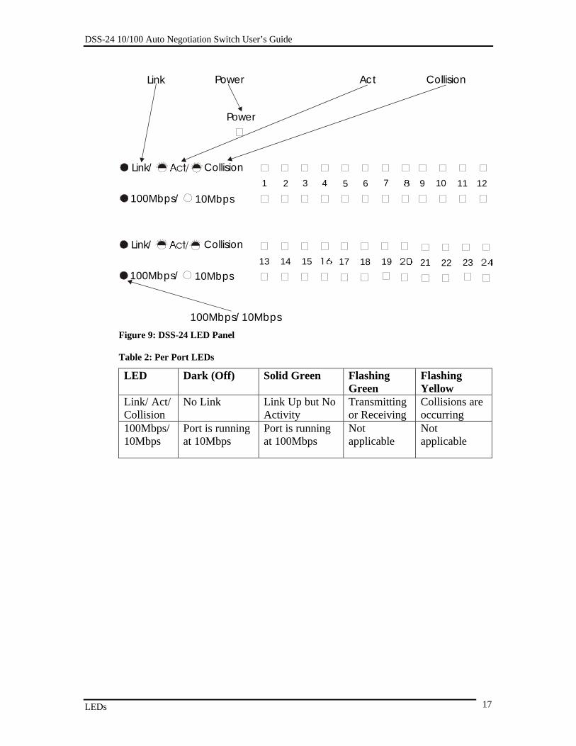
LEDsThe LED panel of the DSS-24, displayed in Figure 9, is designed to give youcritical information at a glance.
The LEDs indicate the following:• Power• Link• Activity• Collision• Speed
All LEDs are described in detail. See Table 2: Per Port LEDs, to determine themeaning of each LED.
Power
The power LED lights when the DSS-24 is powered on. The purpose is to confirmthat the DSS-24 is getting adequate power. The power LED is green when theDSS-24 is powered on and dark when it is powered off.
Link/ Act/ Collision
Solid green indicates the port is linked up. Dark (off) indicates there is no link atthe port.
Flashing green indicates there is activity (transmitting or receiving) at the port.
Flashing yellow indicates collisions are occurring at the port.
100Mbps/ 10Mbps
The 100Mbps/10Mbps LED indicates the speed of the port. The LED is lit whenthe port is working at 100Mbps and dark when the port is working at 10Mbps.
DSS-24 10/100 Auto Negotiation Switch User’s Guide
LEDs 17
Figure 9: DSS-24 LED Panel
Table 2: Per Port LEDs
LED Dark (Off) Solid Green FlashingGreen
FlashingYellow
Link/ Act/Collision
No Link Link Up but NoActivity
Transmittingor Receiving
Collisions areoccurring
100Mbps/10Mbps
Port is runningat 10Mbps
Port is runningat 100Mbps
Notapplicable
Notapplicable
Link/ Collision
100Mbps/ 10Mbps13 17 2114 18 2215 19 23
Link/ Collision
100Mbps/ 10Mbps1 2 3 4 5 6 7 9 10 11 12
Power
PowerLink Act Collision
100Mbps/ 10Mbps

DSS-24 10/100 Auto Negotiation Switch User’s Guide
Managing the DSS-24 18
5
Managing the DSS-24The DSS-24 is an unmanaged switch. You can change two values: the physicalstate of the ports and the flow control. You cannot make any other changes andconfigurations.
The only way to change the configuration is to connect a workstation or laptop tothe DSS-24 with an RS-232 serial cable and make the desired changes. The DSS-24 is not password protected. Anyone who connects to the DSS-24 with an RS-232 cable can make changes.
Follow these steps to begin a management session:1. Attach the male end of an RS-232 serial cable to the RS-232 serial
port located at the rear.
2. Attach the other end to the serial port of a workstation or laptop.
3. Run a terminal or terminal emulation application using thefollowing settings:
• Emulation: VT-100/ANSI compatible• BPS: 19 200• Data bits: 8• Parity: None• Stop bits: 1• Flow Control: None• Enable: Terminal keys
4. Power the DSS-24 on after the connection is established. PressEnter to refresh the screen and display the login panel. See Chapter6, Troubleshooting if the panel does not display properly.
The connection times out after five minutes. Press Enter to reestablish theconnection. This setting cannot be changed or disabled. If you have not doneanything on the DSS-24 for more than five minutes, it will time out. Press Enterone time to refresh the screen.

DSS-24 10/100 Auto Negotiation Switch User’s Guide
Managing the DSS-24 19
Panel ConventionsThe following panel conventions are used on the DSS-24:
• The Arrow and Tab keys can be used to select items.
• The Spacebar is used to toggle to different settings.
• The Backspace key allows you to move backwards through thepanels.
• Control-R refreshes the panel.
• NEXT takes you forward to the next panel.
• PREV takes you back to the previous panel.
• SAVE saves your changes. If settings have been modified, changestake effect.
• EXIT ends the management session.

DSS-24 10/100 Auto Negotiation Switch User’s Guide
Managing the DSS-24 20
PanelsEach panel of the DSS-24 covers eight ports. You will have either two or threepanels. There are no other menus or panels available.
Each panel has four columns: Port, Physical, Flow Control and Link Status.
Port
Port indicates the port number. The ports are numbered on the front panel of theDSS-24. Remember that the MDI-II Uplink port and port one are connected. Ifyou are using the uplink port, then port one is in use.
Physical
Physical refers to the physical state of the port. The ports have five states. Youcan change the physical state a port is in.
Auto is the default port state. Ports in the Auto state automatically negotiate speedand duplex mode. Half duplex means that data is being transmitted in onedirection at a time. Full duplex means data is being transmitted and receivedsimultaneously.
10/Half indicates the port is transmitting and receiving data at 10 Mbps in halfduplex. 10/Full indicates the port is transmitting and receiving data at 10 Mbps infull duplex.
100/Half indicates the port is transmitting and receiving data at 100 Mbps in halfduplex. 100/Full indicates the port is transmitting and receiving data at 100 Mbpsin full duplex.
Flow Control
The Flow Control can be in one of two states: Enabled, the default state, orDisabled. Leaving flow control enabled allows the port to apply flow control asneeded. In full duplex mode, IEEE 802.3x, port based flow control isimplemented.
Flow control can only be enabled or disabled on ports in Auto mode. In forcedmode Flow Control is automatically disabled.
Link Status
The Link Status indicates whether the link to other devices is up or down. LinkDown means there is no link to any other device. Ports that do not have devicesconnected to them will always show a Link Status of Link Down. Ports withdevices connected will indicate the speed and duplex mode the port is running at.

DSS-24 10/100 Auto Negotiation Switch User’s Guide
Managing the DSS-24 21
Configuration ExamplesThe following figures give examples of possible configurations. The figures areexamples. They are intended to illustrate the functions of the DSS-24. Thesettings displayed on your switch may be different.
Remember that the DSS-24 is an unmanaged switch. The DSS-24 can beconnected to the network with no configuration and it will automatically negotiateall speed and duplex settings. Changes should only be made for specific reasons.
The first panel you see when logging in is displayed in Figure 10. The Link Statusis Link Down because no network connections have been made.
Figure 10: No Network Connection

DSS-24 10/100 Auto Negotiation Switch User’s Guide
Managing the DSS-24 22
Ports 1 and 2 have been connected to the network. The DSS-24 has autonegotiated the proper speed and duplex mode, displayed in Figure 11. No furtherconfiguration is necessary.
Figure 11: Auto Negotiation
The speed and duplex mode on port 1 has been manually set. Flow Control wasautomatically disabled when the Physical setting was changed from autonegotiation to forced mode, displayed in Figure 12. On port two, Flow Controlhas been manually set to Disabled by toggling the space bar.
Figure 12: DSS-24 Flow Control Disabled

DSS-24 10/100 Auto Negotiation Switch User’s Guide
Troubleshooting 23
6
TroubleshootingThis troubleshooting section is intended to help you solve the most commonproblems on the DSS-24.
Problem Solution
Cables Faulty cable is the most common source of problems onEthernet and Fast Ethernet networks. Check the cable firstif you are having any problems connecting to a device.
Ethernet is more fault tolerant than Fast Ethernet. If you aremoving from Ethernet to Fast Ethernet, make sure thecables are pinned out correctly. See Chapter 3, NetworkConnections, Cable Specifications, for a diagram showingthe proper cable pin arrangement for Ethernet and FastEthernet.
Port States All ports on the DSS-24 have two modes: auto negotiationmode and forced mode. Ports in auto negotiation mode autonegotiate the proper speed and duplex mode. Ports inforced mode have been manually set to a particular speedand duplex mode. Check the LEDs on the DSS-24 to verifysettings.
The port settings on the DSS-24 and the port settings on thedevice you are connecting to must be the same in order forthem to communicate. Check the speed and duplex settingon both the port and the device you are connecting to.
Power LED is Off Check the three pronged power plug and verify that you aregetting power from the wall socket. If the DSS-24 is on andthe power LED is not working properly, return the DSS-24.If the DSS-24 is not powering on while the power cord isplugged into wall socket, the power supply is not working.Return the unit.
All LEDs are Off Check the power plug and verify that the DSS-24 isreceiving adequate power. Power the DSS-24 off andpower it back on again. Return the unit if the problempersists.
No Link If a cable is plugged into the port and the Link/ Act/Collision LED is dark, check the cable and connection. The

DSS-24 10/100 Auto Negotiation Switch User’s Guide
Troubleshooting 24
default value is that all ports auto negotiate the properspeed and duplex mode. If the port has been manuallyconfigured for a particular speed and duplex mode, verifythat the speed and duplex mode of the port match the speedand duplex mode of the device you are connecting to.
DSS-24 10/100 Auto Negotiation Switch User’s Guide
Appendix A 25
Appendix ADSS-24 Technical Specifications
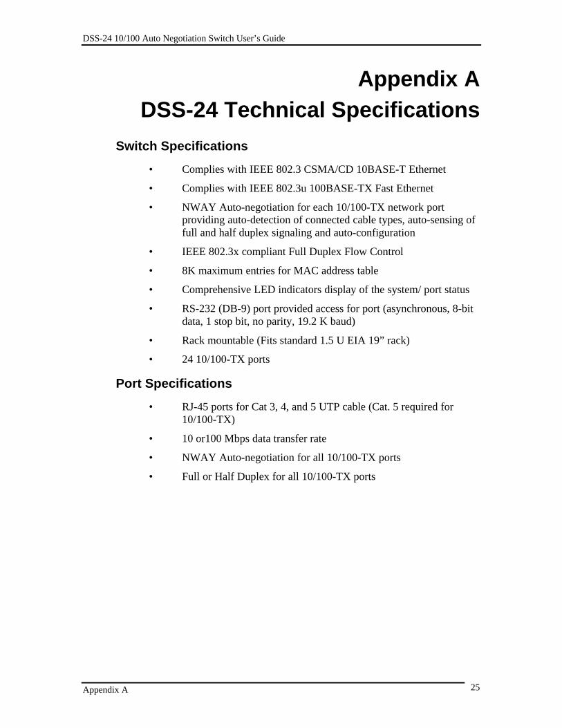
Switch Specifications
• Complies with IEEE 802.3 CSMA/CD 10BASE-T Ethernet
• Complies with IEEE 802.3u 100BASE-TX Fast Ethernet
• NWAY Auto-negotiation for each 10/100-TX network portproviding auto-detection of connected cable types, auto-sensing offull and half duplex signaling and auto-configuration
• IEEE 802.3x compliant Full Duplex Flow Control
• 8K maximum entries for MAC address table
• Comprehensive LED indicators display of the system/ port status
• RS-232 (DB-9) port provided access for port (asynchronous, 8-bitdata, 1 stop bit, no parity, 19.2 K baud)
• Rack mountable (Fits standard 1.5 U EIA 19” rack)
• 24 10/100-TX ports
Port Specifications
• RJ-45 ports for Cat 3, 4, and 5 UTP cable (Cat. 5 required for10/100-TX)
• 10 or100 Mbps data transfer rate
• NWAY Auto-negotiation for all 10/100-TX ports
• Full or Half Duplex for all 10/100-TX ports

DSS-24 10/100 Auto Negotiation Switch User’s Guide
Appendix A 26
General
Standards: IEEE 802.3 10BASE-T EthernetIEEE 802.3u 100-TX Fast EthernetANSI/IEEE Std 802.3 NWAY™ AutoNegotiationIEEE 802.3 Frame types: TransparentIEEE 802.3 MAC layer frame size: 64-1518
Protocol: CSMA/CD, Full Duplex
Data TransferRate:
Fast Ethernet:100 Mbps (half duplex)200 Mbps (full duplex)
Topology: Star
Network Cables: • 10BASE-T:2-pair UTP Cat. 3 (100 m)4-pair UTP Cat. 4, 5 (100 m)EIA/ TIA-568 150-ohm STP (100 m)
• 100-TX:4-pair UTP Cat. 5 (100 m)EIA/ TIA-568B 150-ohm STP (100 m)
Number of Ports:(depending onmodel)
24 x 10/100 Mbps NWAY Ethernet
DSS-24 10/100 Auto Negotiation Switch User’s Guide
Appendix A 27
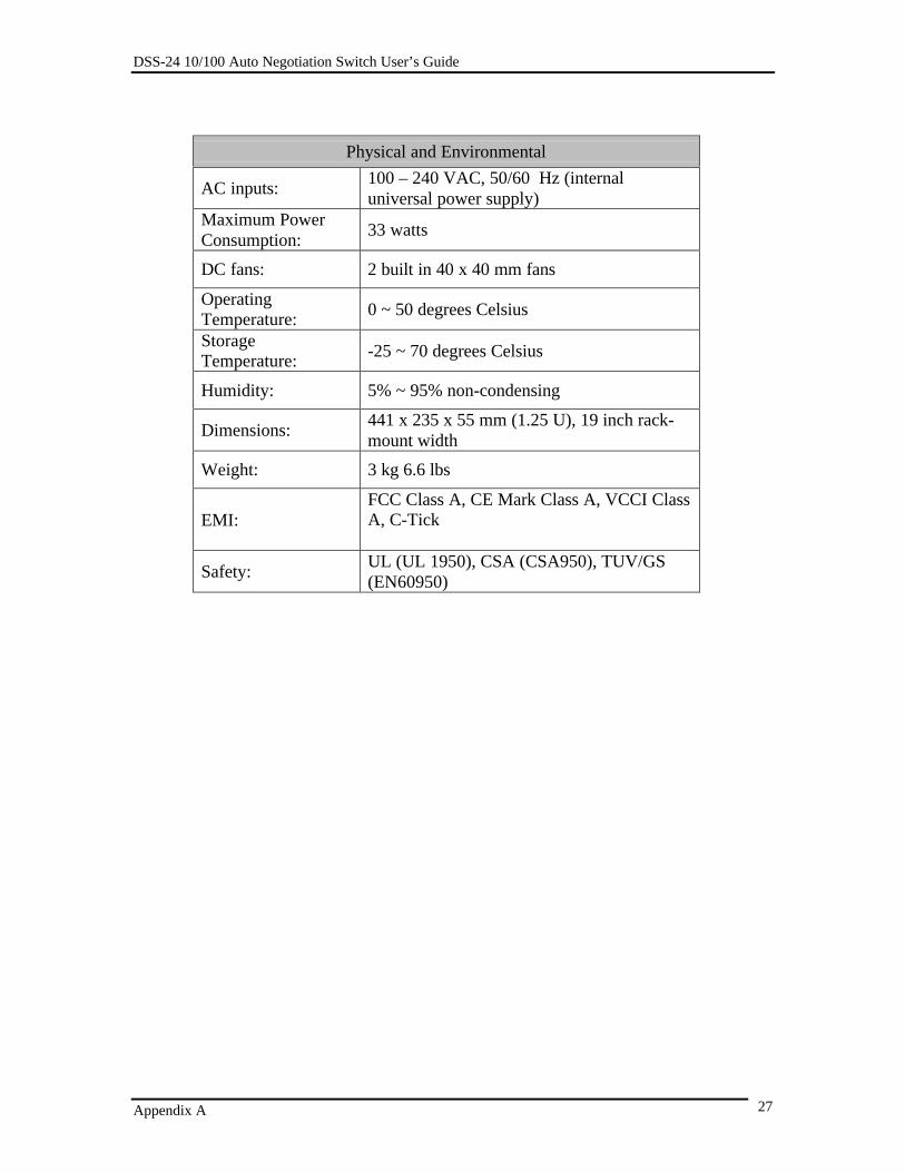
Physical and Environmental
AC inputs:100 – 240 VAC, 50/60 Hz (internaluniversal power supply)
Maximum PowerConsumption:
33 watts
DC fans: 2 built in 40 x 40 mm fans
OperatingTemperature:
0 ~ 50 degrees Celsius
StorageTemperature:
-25 ~ 70 degrees Celsius
Humidity: 5% ~ 95% non-condensing
Dimensions:441 x 235 x 55 mm (1.25 U), 19 inch rack-mount width
Weight: 3 kg 6.6 lbs
EMI:FCC Class A, CE Mark Class A, VCCI ClassA, C-Tick
Safety:UL (UL 1950), CSA (CSA950), TUV/GS(EN60950)
DSS-24 10/100 Auto Negotiation Switch User’s Guide
Appendix A 28
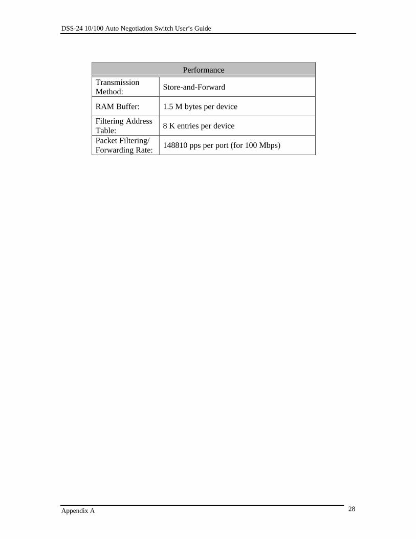
Performance
TransmissionMethod:
Store-and-Forward
RAM Buffer: 1.5 M bytes per device
Filtering AddressTable:
8 K entries per device
Packet Filtering/Forwarding Rate:
148810 pps per port (for 100 Mbps)

29
Index1
100Mbps/ 10Mbps..........................................16
C
Configuration Examples .................................21
D
dimensions.......................................................7
F
features ............................................................2Flow Control ..................................................20front panel........................................................3
I
installation .......................................................7
L
link ................................................................16Link Status.....................................................20
M
management.....................................................5MDI-X port....................................................15
P
Panel Conventions ......................................... 19Panels............................................................ 20Physical......................................................... 20Port ............................................................... 20ports .............................................................. 15power ............................................................ 16
R
rear panel......................................................... 4RS-232 port ................................................... 15RS-232 port settings ...................................... 18
S
side panels....................................................... 4
U
unpacking........................................................ 6Uplink port .................................................... 15