dsp-3000 fog technical manual - university of...
TRANSCRIPT

DSP-
3000
KVH® DSP-3000 Fiber Optic Gyro
Technical Manual

DSP-3000 Fiber Optic Gyro Technical Manual This manual provides detailed guidelines for the proper installation and operation of the KVH DSP-3000 fiber optic gyro (FOG).
Throughout this manual, important information is marked for your attention by these icons:
A helpful tip that either directs you to a related area within the manual or offers suggestions on getting the highest quality out of your system.
An alert to important information regarding procedures, product specifications, or product use.
An electrical safety warning to help identify electrical issues that can be a hazard to either this KVH product or a user.
Information about installation, maintenance, troubleshooting, or other mechanical issues.
Please direct questions, comments, or suggestions to: KVH Industries, Inc. 50 Enterprise Center Middletown, RI 02842-5279 USA Tel: +1 401 847-3327 Fax: +1 401 849-0045 E-mail: [email protected] Internet: www.kvh.com
If you have any comments regarding this manual, please e-mail them to [email protected]. Your input is greatly appreciated!
KVH Part # 54-0215 Rev. C © 2005-2007 KVH Industries, Inc. All rights reserved.
Protected by U.S. and foreign patents

KVH® is a registered trademark of KVH Industries, Inc.

54-0215 Rev. C i
Table of Contents 1 Introduction ........................................................... 1
1.1 Scope of this Manual.....................................................................1
1.2 Product Description ......................................................................1
1.2.1 Output Orientation ...............................................................5
1.2.2 Interface Connector .............................................................5
2 Digital 100 Hz Asynchronous Interface............................ 7
2.1 Description ...................................................................................7
2.1.1 User Commands..................................................................8
2.2 Wiring the Gyro for Digital Asynchronous Operation ................9
2.2.1 Wiring Guidelines ................................................................9
2.3 Preliminary Testing .....................................................................10
2.3.1 Test Procedure ..................................................................10
3 Digital 1000 Hz Asynchronous Interface .........................12
3.1 Description .................................................................................12
3.1.1 Message Structure ............................................................13
3.1.2 Message Content ..............................................................13
3.1.3 Message Rates..................................................................14
3.1.4 Synchronization .................................................................14
3.2 Wiring the Gyro for Digital Asynchronous Operation ..............15
3.2.1 Wiring Guidelines ..............................................................15
3.3 Preliminary Testing .....................................................................16
3.3.1 Test Procedure ..................................................................16
4 Digital 1000 Hz Synchronous Interface...........................18
4.1 Description .................................................................................18
4.1.1 Message Structure ............................................................19
4.1.2 Message Content ..............................................................20
4.1.3 Message Rates..................................................................20

ii 54-0215 Rev. C
4.2 Wiring the Gyro for Digital Synchronous Operation ................21
4.2.1 Wiring Guidelines ..............................................................21
4.3 Preliminary Testing .....................................................................22
4.3.1 Test Procedure..................................................................22
5 Analog Interface .................................................... 24
5.1 Description .................................................................................24
5.1.1 Analog Output Voltage Generation....................................24
5.1.2 Rate Scaling ......................................................................24
5.2 Wiring the Gyro for Analog Operation.......................................25
5.2.1 Wiring Guidelines ..............................................................25
5.3 Preliminary Testing .....................................................................27
5.3.1 Test Procedure..................................................................27
6 Mounting the Gyro .................................................. 28
7 Troubleshooting..................................................... 29
Appendix A Patent Protection*......................................... 30

54-0215 Rev. C 1
1 Introduction 1.1 Scope of this Manual This technical manual supports KVH Industries’ DSP-3000 series fiber optic gyros with digital or analog output. Technical and performance specifications, interfaces, installation and testing guidelines, and a brief troubleshooting guide are included. This manual covers the DSP-3000 model gyros with the following part numbers:
Table 1: Gyro Part Numbers
Part No. Output
02-1222-01 Digital, 100 Hz asynchronous
02-1222-02 Digital, 1000 Hz synchronous
02-1222-03 Analog
02-1222-04 Digital, 1000 Hz master synchronous
02-1222-07 Digital, 1000 Hz asynchronous
1.2 Product Description The DSP-3000 is a single-axis interferometric fiber optic gyro for use in a wide range of applications, including antenna and optical stabilization, navigation, positioning, aerospace (AHRS), IMUs, robotics, and instrumentation. Based on proprietary polarization-maintaining fiber and precision FOG technology, the DSP-3000 employs a digital signal processor and an all-fiber, open loop optical circuit. The gyro measures angular rate of rotation, which can be integrated to allow turning angle to be measured accurately. Operating from a nominal 5 VDC, it outputs a digital or analog message with input rates of up to ±375 degrees per second for digital versions, or ±100 degrees per second for the analog version. The DSP-3000 is self-initializing and ready for use approximately 5 seconds after power is applied.

2 54-0215 Rev. C
Product specifications are listed in Table 2. Please read the entire manual prior to making connections between the unit and your system.
Table 2: Product Specifications
Attribute Rating
Performance
Digital Analog
Maximum Input Rate ±375°/sec ±100°/sec
Scale Factor
1000 ppm, 1σ of full scale, for ±375°/sec
Linearity (room temp)
500 ppm, 1σ of full scale, for ±150°/sec
500 ppm, 1σ of full scale
Temperature Sensitivity 500 ppm, 1σ 500 ppm, 1σ
Error (full rate & temp) 1500 ppm, 1σ 1000 ppm, 1σ
Bias
Offset (room temp) ±20°/hr ±100°/hr
Stability (room temp)* 1°/hr, 1σ 3°/hr, 1σ
Temperature Sensitivity (<1°C/min)
6°/hr, 1σ 20°/hr, 1σ
>40 Hz, 100 Hz asynchronous
Bandwidth (3 dB)
>400 Hz, 1000 Hz synchronous or
asynchronous
100 Hz
100/sec, 100 Hz asynchronous
Update Rate
1000/sec, 1000 Hz synchronous or
asynchronous
2000/sec
Angle Random Walk (noise)* 4°/hr/√Hz 0.0667°/√hr
6°/hr/√Hz 0.1°/√hr
Initialization Time (valid data) <5 sec
* Bias Stability and Angle Random Walk determined by Allan variance method.

54-0215 Rev. C 3
Table 2: Product Specifications (Continued)
Attribute Rating
Electrical
Digital Analog
Input Voltage +5 VDC ±10%
Power Consumption 3 watts maximum (2 watts typical)
Output
38,400 Baud (RS-232), 100 Hz asynchronous
±2 VDC full scale, differential
115,200 Baud (RS-232), 1000 Hz asynchronous
Type
3.072 MHz serial, 1000 Hz synchronous
±1 VDC full scale, single-ended
Format (selectable) Rate, Incremental Angle, or Integrated Angle
Rate
Physical
Dimensions 3.5" x 2.3" x 1.3" (88.9 mm x 58.42 mm x 33.02 mm)
Weight 0.6 lbs (0.27 kg)
Environmental
Operating Temperature -40°F to +167°F (-40°C to +75°C)
Storage Temperature -58°F to +185°F (-50°C to +85°C)
Shock (functional) Functional sawtooth 40 g, 6-10 msec
Random Vibration 20 to 2000 Hz, 8 g rms, operational
MTBF >55,000 hours, ground mobile
In all cases while operating, input rate must not exceed ±500°/second. If the input rate exceeds ±500°/second, physical damage will not occur but the output data will become unreliable, regardless of the validity BIT.

4 54-0215 Rev. C
An interface control drawing (ICD) illustrating the dimensions, connector placement, and mounting holes is provided in Figure 1.
All dimensions are shown in inches [millimeters] format.
Figure 1: Interface Control Drawing

54-0215 Rev. C 5
1.2.1 Output Orientation
The DSP-3000 senses rotation on an axis perpendicular to the plane of the baseplate. An arrow on the product’s serial number label (located on the side of the unit) shows the rotational direction corresponding to a positive output. Looking at the gyro from overhead, a clockwise rotation will produce a positive output.
Figure 2: Clockwise Rotation
To minimize output errors and cross-coupling to the sensitive axis of the gyro, the mounting surface should be parallel to the plane normal to the rotational axis. If this alignment is not observed, the output data will vary as a function of the cosine of the misalignment angle.
1.2.2 Interface Connector
The DSP-3000 is equipped with a 15-pin interface connector of the following type: Tyco Electronics’ single-row Dualobe connector (Tyco part number SSM015L2HN). With the connector positioned at the top of the gyro wall (as shown in Figure 1), pin 1 is located on the right side when viewing the connector head-on. Figure 3 shows the gyro interface connector pins, and Table 3 on the following page lists the function of each pin.
Figure 3: Gyro Connector Pins (Head-on View)
Pin 1Pin 15

6 54-0215 Rev. C
Table 3: Gyro Connector Pin-outs
Pin Function Type Characteristics
1 +5 V PWR Power Positive +5 VDC supply
2 +5 V RTN Power Return Ground
3 Chassis Gnd Shield Ground
4 Rate + Analog Differential with Rate -
5 Rate - Analog Differential with Rate +
6 Analog Gnd Ground Ground Reference for Rate + / Rate -
7 Spare - Reserved for Future Use
8 BIT TTL Built In Test (High Indicates Fault)
9 Tx RS-232 Async Serial Transmit Line
10 Rx RS-232 Async Serial Receive Line
11 Gnd TTL Digital Ground
12 Tclk TTL Sync Serial Port Transmit Clock
13 Tdata TTL Sync Serial Port Transmit Data
14 Tsync TTL Sync Serial Port Transmit Frame Sync
15 Msync TTL Sync Serial Port Receive Frame Sync
For a suitable mating connector, use Tyco Electronics’ single-row Dualobe plug assembly with flying leads (Tyco part number SSL015PC2DCXXXN, where XXX is length in inches). This mating connector, with 12" leads, is available from KVH (KVH part number 32-0780).
The next three sections explain the different interface options:
• Digital 100 Hz Asynchronous: see page 7
• Digital 1000 Hz Asynchronous: see page 12
• Digital 1000 Hz Synchronous: see page 18
• Analog: see page 24

54-0215 Rev. C 7
2 Digital 100 Hz Asynchronous Interface 2.1 Description (KVH Part No. 02-1222-01) Connector pins 9 (transmit) and 10 (receive), with ground pin 11, provide an asynchronous serial interface to the gyro. This interface has the following characteristics:
Type: RS-232
Baud Rate: 38,400 Baud
Parity: None
Data Bits: 8
Stop Bits: 1
Flow Control: None
Both transmit and receive functions are available with this interface. Since transmit (Tx) and receive (Rx) designations refer to the gyro as the source, “transmit” is an output from the gyro, and “receive” is an input to the gyro. The “transmit” output has the following format:
Output Burst Rate: 100/second (approximate, see Note 1)
Output Format: ASCII text consisting of two decimal data words (separated by a space), followed by a carriage return/line feed sequence: (-)xxx.xxxxxx y
(-)xxx.xxxxxx = Data Word 1 y = Data Word 2
Output Data Word 1: Three user-selectable formats:
Rate (in degrees/second) = the average over the interval from the last output; this is the default mode at power-up
Incremental Angle (in degrees) = the angular change from the last output
Integrated Angle (in degrees) = the rotation angle modulo 360 from an arbitrarily user-chosen zero reference (see “Z” on the following page)
Output Data Word 2: BIT; ASCII 1 = “Data Valid,” ASCII 0 = “Fault”
Note 1: The output burst rate may vary, gyro-to-gyro, by ±2 to ±3 percent. There is also a variation over temperature of approximately ±0.2 percent.
The “receive” input supports several user commands. The next section explains how to access the maintenance mode and lists the available configuration commands.

8 54-0215 Rev. C
2.1.1 User Commands
The following single-character user commands to the gyro are supported:
Table 4: Single-character User Commands
Command Function
R Switch output to Rate
A Switch output to Incremental Angle
P Switch output to Integrated Angle
Z Zero the Integrated Angle value
These single ASCII characters are input without a carriage return or line feed. A command may need to be sent more than once for the command to execute.

54-0215 Rev. C 9
2.2 Wiring the Gyro for Digital Asynchronous Operation Use the wiring diagram below as a guide to connect the gyro to your application.
Figure 4: Wiring Diagram (Asynchronous Operation)
1
2
3
4
5
6
7
8
9
10
11
12
13
14
15
1
2
3
4
5
6
7
8
9
5 VDC
RETURN
DC SUPPLY
COMPUTERCOM PORT
RX
TX
SIG GND
+5 VDC
POWER COMMON
RX
TX
CASE GROUND
SIGNAL COMMON
2.2.1 Wiring Guidelines
Be sure to follow the guideline below to ensure optimum performance.
• The chassis ground, pin 3, as well as the housing, should be coupled to the system ground with minimum impedance. The surface on which the gyro is mounted should not inject AC noise onto the gyro housing as it will radiate into the gyro electronics.

10 54-0215 Rev. C
2.3 Preliminary Testing Before connecting and mounting the gyro to your system, a simple familiarization test is suggested if this is your first introduction to the product. This test will also verify proper unit operation and assist in troubleshooting.
Equipment needed to test the gyro: • +5 VDC power supply
• Computer with an RS-232 input and a terminal emulation program (such as Windows Hyperterminal)
• Interface cable with a female 15-pin single-row Dualobe connector on one end and a DB9 connector on the other end, wired as shown in Figure 4 on page 9
2.3.1 Test Procedure
Follow the steps below to test the gyro for proper operation.
1. Place the DSP-3000 module on a flat surface with the mounting surface down.
2. Connect the +5 VDC (±10%) power supply positive to pin 1; connect the negative to pins 2 and 3.
3. Connect the DB9 plug from the test cable harness to the computer’s COM port. Select the serial port (to which the cable was connected), open the test data acquisition program, and select the following communications program settings:
• 38,400 baud
• 8 data bits
• 1 stop bit
• no parity
• no flow control
4. With the gyro held stationary, the indicated mean (30-second average) input rate should be less than 0.005°/s, excluding Earth rate. If no data is received, check the wiring for proper data line connection.
To calculate the Earth rate for your geographical area, use the following formula:
Earth rate = -15.04107 x sin(latitude)
Note: Northern latitudes are positive and southern latitudes are negative.
54-0215 Rev. C 11
5. Grasp the gyro and slowly rotate it in the direction of the arrow on its serial number label. The output data should indicate a positive change.
6. Slowly rotate the gyro in the opposite direction. The output data should indicate a negative change.
7. After the initial 5-second startup, the BIT data word (Data Word 2) should show ASCII 1 (“data valid”) at all times. If the BIT shows ASCII 0 (“fault”), the gyro has malfunctioned.

12 54-0215 Rev. C
3 Digital 1000 Hz Asynchronous Interface 3.1 Description (KVH Part No. 02-1222-07) Connector pin 9, with ground pin 11, provides an asynchronous serial interface to the gyro. This interface has the following characteristics:
Type: RS-232
Baud Rate: 115,200 Baud
Parity: None
Data Bits: 8
Stop Bits: 1
Flow Control: None
The gyro’s output has the following format:
Output Burst Rate: 1000/second (approximate, see Note 1)
Output Format: Each character contains 10 bits:
• 1 start bit (Space, binary 0)
• 8 data bits (1 message byte, starting with LSB)
• 1 stop bit (Mark, binary 1)
An idle line is always marking, that is, in a binary 1 state. Four characters in sequence constitute a basic message.
Note 1: The output burst rate may vary, gyro-to-gyro, by ±2 to ±3 percent. There is also a variation over temperature of approximately ±0.2 percent.

54-0215 Rev. C 13
3.1.1 Message Structure
A basic message is 32 bits (4 bytes) long. The most significant byte (MSB) is sent first. Table 5 and Figure 5 define the bits in the message.
Table 5: Message Bits
Bit(s) Usage Values
31 Message Validity 0 = Hardware BIT signal is low or contents are invalid
1 = Hardware BIT OK and contents are valid
30, 29 Synchronization See Section 3.1.4, “Synchronization”
28, 27 Type 0 = Rate data
1 = Incremental Angle data
2 = Integrated Angle data
26 Parity See Note 1
25 - 0 Content See Section 3.1.2, “Message Content”
Note 1: Preset Bit 26 to 1, then compute Bit 26 = Bit 0 ⊕ Bit 1 ⊕ Bit 2…⊕ Bit 25 ⊕ Bit 26 ⊕ Bit 27 ⊕ Bit 28 ⊕ Bit 29 ⊕ Bit 30 ⊕ Bit 31.
Figure 5: Message Structure
3.1.2 Message Content
Use of the 26-bit Content field depends on the Type bits, as noted below.
Rate Data
When the Type bits indicate Rate Data, the contents are in two’s complement format. The LSB represents 60 µ°/s, or 0.216°/hr.
Incremental Angle Data
When the Type bits indicate Incremental Angle Data, the contents are in two’s complement format. The LSB represents 6 µ°.
Byte 1 Byte 2 Byte 3 Byte 4
24 31 16 23 8 15 0 7
Val
idity
Syn
c
Type
Par
ity
Con
tent
= Start Bit = Stop BitCon
tent
Note: In asynchronous protocol, the least significant bit (LSB) is sent first.

14 54-0215 Rev. C
Integrated Angle Data
When the Type bits indicate Integrated Angle data, the contents can be interpreted based on the table below.
Table 6: Message Contents (Type Bits = Integrated Angle Data)
Bit(s) Usage Values
25, 24, 23 360° modulo counter Increment when crossing from 359 to 0. Decrement when crossing from 0 to 359. Bit 25 is MSB; Power-up value is 0.
22 - 0 0 <= integrated angle < 360 LSB (bit 0) value is 42.91534 µ°.
3.1.3 Message Rates
The rate at which the Rate or Integrated Angle information actually updates depends on the application. Standard rate is 1000 Hz.
3.1.4 Synchronization
Message bits 29 and 30 make up the synchronization field for each message. These bits conform to an eight-bit, continuously repeating pattern, as shown below.
1st Message 00
2nd Message 01
3rd Message 10
4th Message 11
This synchronization pattern allows you to design a receiver algorithm that can detect the first byte of a message. For example, you could create a “state machine” with two modes: Acquisition and Locked. In Acquisition mode, the state machine would examine the sixth and seventh bits of each byte. Once it finds a byte position that exhibits the defined synchronization pattern for 10 cycles in a row, and no other byte position has exhibited the pattern for more than 3 of the last 10 cycles, the state machine would designate that byte position as the first byte in the four-byte message. The state machine would then enter Locked mode. In Locked mode, the state machine would continue to monitor each byte. If the byte position that it designated as “first” does not match the synchronization pattern for more than 3 out of 10 cycles, and a different byte position matches 7 or more, the state machine would then designate the different byte position as the first byte.

54-0215 Rev. C 15
3.2 Wiring the Gyro for Digital Asynchronous Operation Use the wiring diagram below as a guide to connect the gyro to your application.
Figure 6: Wiring Diagram (Asynchronous Operation)
3.2.1 Wiring Guidelines
Be sure to follow the guideline below to ensure optimum performance.
• The chassis ground, pin 3, as well as the housing, should be coupled to the system ground with minimum impedance. The surface on which the gyro is mounted should not inject AC noise onto the gyro housing as it will radiate into the gyro electronics.
1
2
3
4
5
6
7
8
9
10
11
12
13
14
15
1
2
3
4
5
6
7
8
9
5 VDC
RETURN
DC SUPPLY
COMPUTERCOM PORT
RX
SIG GND
+5 VDC
POWER COMMON
TX
CASE GROUND
SIGNAL COMMON

16 54-0215 Rev. C
3.3 Preliminary Testing Before connecting and mounting the gyro to your system, a simple familiarization test is suggested if this is your first introduction to the product. This test will also verify proper unit operation and assist in troubleshooting.
Equipment needed to test the gyro: • +5 VDC power supply
• Computer with an RS-232 input and a test data acquisition program (customer-supplied)
• Interface cable with a female 15-pin single-row Dualobe connector on one end and a DB9 connector on the other end, wired as shown in Figure 6 on page 15
3.3.1 Test Procedure
Follow the steps below to test the gyro for proper operation.
1. Place the DSP-3000 module on a flat surface with the mounting surface down.
2. Connect the +5 VDC (±10%) power supply positive to pin 1; connect the negative to pins 2 and 3.
3. Connect the DB9 plug from the test cable harness to the computer’s COM port. Select the serial port (to which the cable was connected), open your test data acquisition program, and select the following communications program settings:
• 115,200 baud
• 8 data bits
• 1 stop bit
• no parity
• no flow control
4. With the gyro held stationary, the indicated mean (30-second average) input rate should be less than 0.005°/s, excluding Earth rate. If no data is received, check the wiring for proper data line connection.
To calculate the Earth rate for your geographical area, use the following formula:
Earth rate = -15.04107 x sin(latitude)
Note: Northern latitudes are positive and southern latitudes are negative.

54-0215 Rev. C 17
5. Grasp the gyro and slowly rotate it in the direction of the arrow on its serial number label. The output data should indicate a positive change.
6. Slowly rotate the gyro in the opposite direction. The output data should indicate a negative change.
7. After the initial 5-second startup, the Message Validity bit (Bit 31 of the data message) should show binary 1 (“data valid”) at all times. If the Message Validity bit shows binary 0 (“fault”), the gyro has malfunctioned.

18 54-0215 Rev. C
4 Digital 1000 Hz Synchronous Interface 4.1 Description (KVH Part No. 02-1222-02 & 02-1222-04) The high-speed transistor-to-transistor level (TTL) synchronous serial interface provides the same performance as the asynchronous interface, but with a standard output rate of 1000/sec. Figure 7 shows the typical signal timing for the interface.
Figure 7: High-speed Synchronous Signal Timing
The characteristics of the synchronous serial interface are listed in Table 7.
Table 7: Synchronous Serial Interface Characteristics
Signal Type
BIT (pin 8) – Built-in Test TTL Output Low = OK, High = failure
Gnd (pin 11) – Ground Signal ground
Tclk (pin 12) – Clock TTL Output
Tdata (pin 13) – Serial Data TTL Output 1 = High
Tsync (pin 14) – Frame Sync TTL Output Active high
Msync (pin 15) – Master Sync Optional
TTL Input Active high
All signals are standard TTL, Active High, Logic Level 3.3V
Dat
a
Par
ityTclk (T=325ns)
Tsync
Tdata
BIT
N/A
Type
025262728293031
145µs±14.5µs
Msync(Optional)

54-0215 Rev. C 19
The BIT signal operates independently of the other signals in the interface.
The Clock rate is 3.072 MHz.
The Serial Data and Frame Sync are stable when the clock signal’s rising edge occurs. The Data and Frame Sync change states when the clock signal’s falling edge occurs.
The Frame Sync signal becomes active high for the duration of the data message. The Frame Sync becomes active on the falling edge where the MSB of the message is first presented on the Data line. The Frame Sync becomes inactive on the falling edge following the rising edge that is used to clock into the receiver the LSB of the message. The Frame Sync remains inactive for at least one bit’s time between messages. When there is no message present on the interface, the Frame Sync line is set to 0.
The optional MSync input is a standard TTL clock input signal with a frequency equal to the gyro output rate. The MSync signal should have a duty cycle of 40-60%, and the frequency tolerance should be 100 ppm or better. When the MSync signal becomes active high, the data message shall begin on the Data line in about 145 µs ±10%.
4.1.1 Message Structure
The basic message is 32 bits long. The MSB is sent first. Table 8 defines the bits in the message.
Table 8: Message Bits
Bit(s) Usage Values
31 Message Validity
0 = Hardware BIT signal is low or contents are invalid
1 = Hardware BIT OK and contents are valid
30, 29 Not Used N/A
28, 27 Type 0 = Rate data
1 = Incremental angle data
2 = Integrated angle data
26 Parity Odd parity
25 - 0 Content See Section 4.1.2, “Message Content”

20 54-0215 Rev. C
4.1.2 Message Content
Use of the 26-bit Content field depends on the Type bits, as noted below.
Rate Data
When the Type bits indicate Rate Data, the contents are in two’s complement format. The LSB represents 60 µ°/s, or 0.216°/hr.
Incremental Angle Data
When the Type bits indicate Incremental Angle Data, the contents are in two’s complement format. The LSB represents 6 µ°.
Integrated Angle Data
When the Type bits indicate Integrated Angle data, the contents can be interpreted based on the table below.
Table 9: Message Contents (Type Bits = Integrated Angle Data)
Bit(s) Usage Values
25, 24, 23 360° modulo counter Increment when crossing from 359 to 0. Decrement when crossing from 0 to 359. Bit 25 is MSB; Power-up value is 0.
22 – 0 0 <= integrated angle < 360 LSB (bit 0) value is 42.91534 µ°.
4.1.3 Message Rates
The rate at which the Rate or Integrated Angle information actually updates depends on the application. Standard rate is 1000 Hz.

54-0215 Rev. C 21
4.2 Wiring the Gyro for Digital Synchronous Operation Use the wiring diagram below as a guide to connect the gyro to your application.
Figure 8: Wiring Diagram (Synchronous Operation)
1
2
3
4
5
6
7
8
9
10
11
12
13
14
15
5 VDC
RETURN
DC SUPPLY+5 VDC
POWER COMMON
CASE GROUND
Tdata
Tsync
Tclk
BIT
CUSTOMERINTERFACE
SIGNAL COMMON
Msync (Optional)
4.2.1 Wiring Guidelines
Be sure to follow the guidelines below to ensure optimum performance.
• The chassis ground, pin 3, as well as the housing, should be coupled to the system ground with minimum impedance. The surface on which the gyro is mounted should not inject AC noise onto the gyro housing as it will radiate into the gyro electronics.
• Twisted-shielded-pair should be used to connect the gyro output to the user’s interface. Cables should be as short as possible, not to exceed 12" (30 cm) in length.
22 54-0215 Rev. C
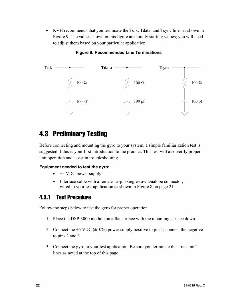
• KVH recommends that you terminate the Tclk, Tdata, and Tsync lines as shown in Figure 9. The values shown in this figure are simply starting values; you will need to adjust them based on your particular application.
Figure 9: Recommended Line Terminations
4.3 Preliminary Testing Before connecting and mounting the gyro to your system, a simple familiarization test is suggested if this is your first introduction to the product. This test will also verify proper unit operation and assist in troubleshooting.
Equipment needed to test the gyro: • +5 VDC power supply
• Interface cable with a female 15-pin single-row Dualobe connector, wired to your test application as shown in Figure 8 on page 21
4.3.1 Test Procedure
Follow the steps below to test the gyro for proper operation.
1. Place the DSP-3000 module on a flat surface with the mounting surface down.
2. Connect the +5 VDC (±10%) power supply positive to pin 1; connect the negative to pins 2 and 3.
3. Connect the gyro to your test application. Be sure you terminate the “transmit” lines as noted at the top of this page.
Tclk
100 Ω
100 pf
Tdata
100 Ω
100 pf
Tsync
100 Ω
100 pf

54-0215 Rev. C 23
4. With the gyro held stationary, the indicated mean (30-second average) input rate should be less than 0.005°/s, excluding Earth rate. If no data is received, check the wiring for proper data line connection. If a parity error occurs, check your terminations.
To calculate the Earth rate for your geographical area, use the following formula:
Earth rate = -15.04107 x sin(latitude)
Note: Northern latitudes are positive and southern latitudes are negative.
5. Grasp the gyro and slowly rotate it in the direction of the arrow on its serial number label. The output data should indicate a positive change.
6. Slowly rotate the gyro in the opposite direction. The output data should indicate a negative change.
7. After the initial 5-second startup, the BIT indicator (at gyro pin 8) should show TTL Low (less than +0.6 VDC) at all times. If the BIT shows TTL High (greater than +2.4 VDC), the gyro has malfunctioned.
BIT information is also provided as part of the data message (at Bit 31).

24 54-0215 Rev. C
5 Analog Interface 5.1 Description (KVH Part No. 02-1222-03) Connector pins 4 (rate +) and 5 (rate -), with ground pin 6, provide an analog interface to the gyro. This interface provides a linear rate range of ±100°/second. Temperature compensation tables are used to minimize bias drift and improve scale factor accuracy and linearity versus temperature. The analog interface provides a true differential output at ±2 VDC (between pins 4 and 5), output to output. Alternately, a single-ended output of ±1 VDC can be used between pins 4 (rate +) and 6 (ground).
The polarity sense may be changed by reversing the wiring to the output pins. Normal sense is clockwise “+” when looking at the gyro from above.
The asynchronous serial output is also provided with the analog option. As analog output performance is optimized for this configuration, there may be some reduction in performance from the digital gyro output. The asynchronous output data rate remains at 100 Hz with a maximum gyro input rate of ±375°/second.
5.1.1 Analog Output Voltage Generation
As the gyro rate signal is digitally generated, it must be converted to analog voltages in the gyro using a 16-bit digital-to-analog converter (DAC) with a rate resolution of (200 deg/sec)/216 or 0.00305 deg/sec/bit.
The DAC output is low-pass filtered at 170 Hz. The 3-dB bandwidth was selected at 170 Hz so as to maintain a 45° phase at 100 Hz to aid in servo loop closures.
5.1.2 Rate Scaling
The differential output of the gyro is scaled for ±2 VDC for ±100°/sec or 20 mV/deg/sec into an impedance of 10 K ohms or greater. A lower load impedance could increase the scale factor error slightly. Input rates of up to ±500°/sec will not harm the gyro other than the expected error during the transient. Recovery occurs within 1 second.

54-0215 Rev. C 25
5.2 Wiring the Gyro for Analog Operation Use the wiring diagram below as a guide to connect the gyro to your application.
Figure 10: Wiring Diagram (Analog Operation)
1
2
3
4
5
6
7
8
9
10
11
12
13
14
15
5 VDC
RETURN
DC SUPPLY+5 VDC
POWER COMMON
CASE GROUND
RATE - (NEGATIVE)
RATE + (POSITIVE)
CUSTOMERINTERFACE
GROUND REFERENCE
5.2.1 Wiring Guidelines
Wiring interfaces are critical in a gyro such as the DSP-3000, particularly for analog signals. Be sure to follow the guidelines below to ensure optimum performance.
• The chassis ground, pin 3, as well as the housing, should be coupled to the system ground with minimum impedance. The surface on which the gyro is mounted should not inject AC noise onto the gyro housing as it will radiate into the gyro electronics.
• Current not related to gyro output signal should never be conducted on the analog ground.
• The differential output of the gyro should be connected to a differential input of an ADC or through a differentially configured operational amplifier. The analog ground should therefore be tied to the signal ground at those interfaces, thus reducing common mode noise.

26 54-0215 Rev. C
• Twisted-shielded-pair should be used to connect the gyro output to the user interface. The shield may be connected to analog ground at the gyro and signal ground in the user’s electronic interface.
• Due to the low-level analog voltages from the gyro, cables longer than 12" (30 cm) to the user’s interface are not recommended without buffering.
• As the output drivers on pins 4 and 5 in the gyro are both active devices, neither pin should ever be tied to ground.
• If the gyro differential output is tied into a system where another sensor utilizes a 2.5-volt reference that would be connected directly to one of the gyro outputs, isolation is necessary.

54-0215 Rev. C 27
5.3 Preliminary Testing Before connecting and mounting the gyro to your system, a simple familiarization test is suggested if this is your first introduction to the product. This test will also verify proper unit operation and assist in troubleshooting.
Equipment needed to test the gyro: • +5 VDC power supply
• Voltmeter
5.3.1 Test Procedure
Follow the steps below to test the gyro for proper operation.
1. Place the DSP-3000 module on a flat surface with the mounting surface down.
2. Connect the +5 VDC (±10%) power supply positive to pin 1; connect the negative to pin 2.
3. Connect the voltmeter across pins 4 (positive) and 5 (negative) of the gyro interface connector.
4. Grasp the gyro and slowly rotate it in the direction of the arrow on its serial number label. The voltage (shown on the voltmeter) should increase.
5. Slowly rotate the gyro in the opposite direction. The voltage (shown on the voltmeter) should go negative.
6. Connect the voltmeter across pins 8 (positive) and 6 (negative) of the gyro interface connector. After the initial 5-second startup, the voltage should show TTL Low (less than +0.6 VDC) at all times. If the BIT shows TTL High (greater than +2.4 VDC), the gyro has malfunctioned.

28 54-0215 Rev. C
6 Mounting the Gyro The DSP-3000 gyro is easily mounted to a structure using the four #8-32 tapped mounting holes on the base of the enclosure (see Figure 11). The mounting surface should be flat, less than 0.005" (0.127 mm) peak-to-peak, pad-to-pad. The material should be greater than 0.2" (5 mm) thick with the overall stiffness of the structure designed to be compatible with the natural frequency specified for the gyro or as required for the specific installation. Chassis ground must be mechanically connected to the gyro housing for shielding.
Figure 11: Gyro Mounting Holes (Bottom View)
Apply no greater than 8 in-lbs of torque when securing the gyro to the mounting surface. Tightening mounting screws any greater may affect the gyro’s performance.
Performance of the gyro as a sensor is determined by the design of the mounting structure as well as the gyro’s mechanical components. The mounting structure material should be fabricated from a material, such as aluminum, that has a low thermal time constant. In addition, KVH does not recommend mounting the gyro near equipment that generates time-varying magnetic fields (i.e., stepper motors, servomotors, or solenoids).

54-0215 Rev. C 29
7 Troubleshooting This section is intended to provide a simple means of determining if a problem exists in the KVH DSP-3000 gyro and assumes that the unit has passed the bench testing described in previous sections.
The DSP-3000 is supplied as a sealed unit. Breaking the QA seals voids the warranty and may violate the contract under which the unit was supplied.
The warranty does not apply if the unit has been damaged by misuse or as the result of service or modification other than by KVH Industries.
Table 10: Troubleshooting
Symptom Possible Cause Action
No DC power Check power (measure power at the gyro)
No output
Bad cable Check cable and terminal emulation setup (no control signal)
BIT line level (pin 8) is TTL High
Internal fault Replace gyro
Faulty ground Ground shield at gyro end only Erratic or low output
Magnetic field near gyro Check for new wiring or equipment
High noise Ground loop Check grounds and grounding
Technical Support
For technical support, please e-mail your question or a description of your problem to [email protected].

30 54-0215 Rev. C
Appendix A Patent Protection* One or more of the following U.S. and international patents protect the technology in KVH fiber optic gyros:
Patent Numbers AU 728699 AU 750301 DE 0 254 462 DE 60002436 DE 69509587 DE 69722994 DE 69734809.1 FR 0 254 462 FR 0 687 892 FR 0802397 FR 0838712 FR 1151309 GB 0 254 462 GB 0 687 892 GB 0802397 GB 0838712 GB 1151309 GB 1261880 GB 2299668(B) JP 2076012 US 4,712,866 US 4,773,759 US 4,818,071 US 4,950,318 US 5,120,130 US 5,126,666 US 5,153,676
US 5,340,371 US 5,444,534 US 5,481,358 US 5,512,904 US 5,552,887 US 5,739,944 US 5,768,462 US 6,041,149 US 6,134,356 US 6,351,310 B1 US 6,370,289 B1 US 6,429,939 US 6,441,779 US 6,466,596 US 6,535,657 US 6,539,134 US 6,542,651 US 6,563,589 US 6,594,020 US 6,703,821 US 6,707,558 US 6,718,097 US 6,763,153 US 6,836,334 US 6,864,347 US 6,891,622 US 7,120,323
* Additional patents pending

KVH Industries Limited Warranty DSP-3000
LIMITED WARRANTY ON HARDWARE
KVH Industries, Inc. warrants the KVH Fiber Optic Gyro purchased against defects in materials and workmanship for a period of ONE (1) year from the date of original retail purchase by the original purchaser. If you discover a defect, KVH will, at its option, repair, replace or refund the purchase price of the product at no charge to you, provided you return it during the warranty period, transportation charges prepaid, to the factory direct.
Please attach your name, address, telephone number, a description of the problem and a copy of the bill of sale or sales receipt as proof of date of original retail purchase, to each product returned to warranty service.
This Limited Warranty does not apply if the product has been damaged by accident, abuse, misuse or misapplication or has been modified without the written permission of KVH; if any KVH serial number has been removed or defaced; or if any factory-sealed part of the system has been opened without authorization.
THE EXPRESS WARRANTIES SET FORTH ABOVE ARE THE ONLY WARRANTIES GIVEN BY KVH WITH RESPECT TO ANY PRODUCT FURNISHED HEREUNDER; KVH MAKES NO OTHER WARRANTIES, EXPRESS, IMPLIED OR ARISING BY CUSTOM OR TRADE USAGE, AND SPECIFICALLY DISCLAIMS ANY WARRANTY OF MERCHANTABILITY OR OF FITNESS FOR A PARTICULAR PURPOSE. SAID EXPRESS WARRANTIES SHALL NOT BE ENLARGED OR OTHERWISE AFFECTED BY TECHNICAL OR OTHER ADVICE OR SERVICE PROVIDED BY KVH IN CONNECTION WITH ANY PRODUCT.
KVH’s liability in contract, tort or otherwise arising out of or in connection with any product shall not exceed the price paid for the product. IN NO EVENT SHALL KVH BE LIABLE FOR SPECIAL, PUNITIVE, INCIDENTAL, TORT OR CONSEQUENTIAL DAMAGES OR LOST PROFITS OR GOODWILL (INCLUDING ANY DAMAGES RESULTING FROM LOSS OF USE, DELAY IN DELIVERY OR OTHERWISE) ARISING OUT OF OR IN CONNECTION WITH THE PERFORMANCE OR USE OR POSSESSION OF ANY PRODUCT, OR ANY OTHER OBLIGATIONS RELATING TO THE PRODUCT, EVEN IF KVH HAS BEEN ADVISED OF THE POSSIBILITY OF SUCH DAMAGES.
If any implied warranty, including implied warranties of merchantability and fitness for a particular purpose, cannot be excluded under applicable law, then such implied warranty shall be limited in duration to ONE (1) YEAR from the date of the original retail purchase of this product by the original purchaser.
Some states do not allow the exclusion or limitation of implied warranties or liability for incidental or consequential damages, so the above limitations may not apply to you. This warranty gives you specific legal rights, and you may also have other rights which vary from state to state.

DSP3
000_
cove
r
KVH Industries, Inc. 50 Enterprise Center • Middletown, RI 02842-5279 • U.S.A.
Phone: +1 401 847-3327 • Fax: +1 401 849-0045 • E-mail: [email protected] • Internet: www.kvh.com
KVH® is a registered trademark of KVH Industries, Inc.
®