ds.130 visual design of pavement surfaces - southwark
TRANSCRIPT
Southwark Streetscape Design Manual SSDM/DSR standard DS.130 1
DS.130 Visual design of pavement surfaces
Rev. Status Created by Date Approved by Date
A Final D.Farnham/D.Vasquez-Rossainz 27.02.12 D.Waters 28.02.12
B Final D.Farnham/D.Vasquez-Rossainz 23.03.12 D.Waters 10.04.12
C Final D.Farnham 29.01.13 D.Waters 08.02.13
D Final D.Farnham 06.11.13 D.Waters 14.11.13
E Final G Lake 24.05.19 D Foden 19.06.19
Southwark Streetscape Design Manual SSDM/DSR standard DS.130 2
Table of Contents
1. Introduction………………….…3
1.1 Notes…………………………………..3
2. General surfacing material requirements applicable to carriageways, footways and other non-carriage- way areas …………………..….3
2.1 SSDM Surfacing Material palettes and departures from these….……..3
2.1.1 General………………………………….4 2.1.2 Further requirements about the
application of palettes within particular Specification areas……….6
2.1.3 Further requirements about the application of palettes within Highway maintenance projects……..7
2.1.4 Use of alternative natural stone materials within publicly maintained streets and spaces……..7
2.2 Total number of surfacing materials that may be used within a given street or space…….8
2.3 Number of different colours and size gauges in which a surfacing material may be used……………….9
2.3.1 Size gauges…………………………….9 2.3.2 Colours, tones and finishes………..10
2.4 Use of intermediary restraints within Surface Zones.……………..11
2.5 Infill within surfaces using HBM, concrete or small unit pavers.…….12
2.6 Detailing around bases of items of street furniture………….……….13
2.7 General laying requirements and guidance for modular unit surfaced pavements……………….13
2.7.1 Surface laying arrangement drawings…………………………….…13
2.7.2 Observance of British Standards code of practice……………………....14
2.7.3 Use of edging frames to boundaries with edge restraints…...14
2.7.4 Number of packs to be used when
laying……………………………………..15 2.7.5 Consideration of movement joints......15
3. Specific further requirements for footways and other non-carriageway pavements………15
3.1 Laying patterns for modular unit surfaced pavements…………….15
3.2. Boundary details…………...................16 3.2.1 To rear of footway.……………………....16 3.2.2 To front of footway.………………..…....17 3.2.3 Within footways……………………….....17 3.2.4 Where footways lead into
unadopted areas……………..…….........17 3.2.5 Land ownership boundaries………......17
3.3 Surface channels in footways………17
4. Specific further requirements for carriageway pavements…..18
4.1 Extent of modular unit surfaced areas within carriageways…………..18
4.2 Modular unit type and laying patterns…………………………..……..18
4.2.1 Unbound modular surfaces…………....18 4.2.2 Bound modular surfaces…………..…...18
4.3 Boundary features where carriageways lead into unadopted areas………………..……..18
Appendix A Detailed requirements for the number of materials that may be used to Principle Surface Zones in different Specification Areas……………20
Appendix B Typical Surround Details……..22
Southwark Streetscape Design Manual SSDM/DSR standard DS.130 3
1. Introduction
1.1 Note
a. This standard explains requirements about the visual design of pavement surfaces. It is applicable to carriageway, footway and cycleway pavements and indeed all other types of pavement. Amongst other things its requirements address bonding patterns, bond orientation and the appearance of units. The requirements apply both to items in SSDM Surfacing Material palettes and materials not within these that designers would like to request departure to use.
b. See the SSDM Materials palette for details of materials that are noted in parenthesis, e.g. [C-PQC-C40]. This provides a quick reference look up list for relevant Southwark Highway Specification clauses.
c. See the SSDM webpages at www.southwark.gov.uk/ssdm
1.2 Discussion
a. For all the underlying structural complexity of pavements, it is their surfacing that most influences perceptions about their quality (as well as that of the broader streetscape). Laying patterns and their orientations, joint widths, and the type and variety of materials used can all effect this. Even where high quality materials are used, the wrong laying pattern or the mixing in of discordant other materials may spoil appearance. Whilst distinctive design is always welcome, too often in the past the urge to be different and so to experiment with surfaces has proved ultimately unsuccessful in visual terms.
b. These same factors must be balanced with ease of maintenance. Whilst a laying pattern may be attractive, if it does not provide the necessary degree of structural interlock to cope with the forces created by any vehicles passing over it (e.g. sideways forces in the surface course created by breaking or turning) this may ultimately lead to pavement failure. This is a particular concern where units are laid unbound (e.g.
bedded and jointed using sand or crushed rock rather than mortar). Similarly, whilst it may be possible to design a visually harmonious paving scheme that uses multiple mixed materials, this may create issues during both initial construction and later reinstatement and maintenance if matching replacements for these cannot easily be sourced.
c. The requirements in this standard seek to balance these concerns. As ever, what looks good on the day a newly constructed pavement is opened must be balanced with what it will look like in the coming years after it has been subject to vehicle trafficking, spillages, and almost inevitable openings by Statutory Undertakers (public utility companies) as they place and maintain new and existing apparatus under the street.
2. General surfacing material requirements applicable to carriageways, footways and other non-carriageway areas
Principle Surface Zones
Secondary Surface Zones
Main footway/ footpath surface
Raised table plateau surface
Traffic carpet plateau surface
Main carriageway surface
Parking bay surface
Vehicle crossing plateau surface
Cycle track surface
Vehicle crossing ramp face
Raised table ramp face
Traffic carpet ramp face
Kerbs and edge restraint
Intermediary restraint
Edge and centre of carriageway channel
Tactile surface
Tree pit surface
Deterrent surface
Trim
NOTE Principle Surface Zones are the dominant surfaces within the street that make up the vast majority of their area. Secondary Surface Zones are much smaller surfaces used for detailing and embellishment.
Table 1 – Pavement Surface Zones
Southwark Streetscape Design Manual SSDM/DSR standard DS.130 4
2.1 SSDM Surfacing Material palettes and departures from these
2.1.1 General
a. The surface materials used to pavements should be as permitted for the Pavement Surface Zone in question (see Table 1) within the SSDM Surfacing Material palette(s) for the SSDM/RP designation(s) for that location (though see section 0). Use of alternative materials is subject to the following (though see also note).
i. Publicly maintained streets and spaces
Use of alternative materials requires agreement to a departure and potentially commuted sums.
Table 2 explains the level of departure required in different circumstances (if any) and whether associated commuted sums may also be required
See also section 2.1.4 about the use of alternative natural stone materials.
ii. Private streets and spaces
Use of alternative materials may be permitted by level 1 departure. Proposed alternatives must:
be visually complimentary to the standard materials required as per the SSDM Surfacing Material palette(s) for the SSDM/RP designation(s) for that location
of equal or greater overall quality
meet all other requirements as per this standard and standard DS.601 (unless separate departure from these is obtained).
NOTE: The surfacing materials included in SSDM Surfacing Palettes have been selected to meet with the wider requirements of this standard and the specific structural requirements of standard DS.601. Any proposed alternative materials must also meet with these other requirements unless departure from these is also specifically requested and granted.
Southwark Streetscape Design Manual SSDM/DSR standard DS.130 5
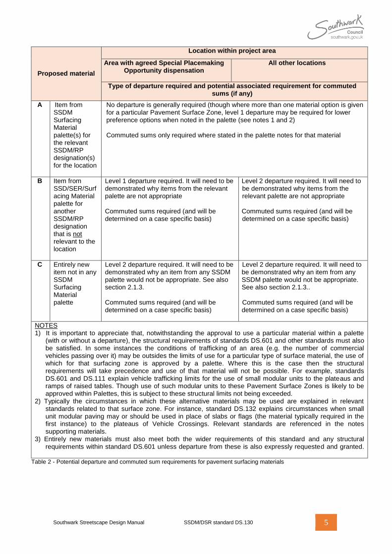
Proposed material
Location within project area
Area with agreed Special Placemaking Opportunity dispensation
All other locations
Type of departure required and potential associated requirement for commuted sums (if any)
AA A
Item from SSDM Surfacing Material palette(s) for the relevant SSDM/RP designation(s) for the location
No departure is generally required (though where more than one material option is given for a particular Pavement Surface Zone, level 1 departure may be required for lower preference options when noted in the palette (see notes 1 and 2) Commuted sums only required where stated in the palette notes for that material
B Item from SSD/SER/Surfacing Material palette for another SSDM/RP designation that is not relevant to the location
Level 1 departure required. It will need to be demonstrated why items from the relevant palette are not appropriate Commuted sums required (and will be determined on a case specific basis)
Level 2 departure required. It will need to be demonstrated why items from the relevant palette are not appropriate Commuted sums required (and will be determined on a case specific basis)
C Entirely new item not in any SSDM Surfacing Material palette
Level 2 departure required. It will need to be demonstrated why an item from any SSDM palette would not be appropriate. See also section 2.1.3. Commuted sums required (and will be determined on a case specific basis)
Level 2 departure required. It will need to be demonstrated why an item from any SSDM palette would not be appropriate. See also section 2.1.3.. Commuted sums required (and will be determined on a case specific basis)
NOTES 1) It is important to appreciate that, notwithstanding the approval to use a particular material within a palette
(with or without a departure), the structural requirements of standards DS.601 and other standards must also be satisfied. In some instances the conditions of trafficking of an area (e.g. the number of commercial vehicles passing over it) may be outsides the limits of use for a particular type of surface material, the use of which for that surfacing zone is approved by a palette. Where this is the case then the structural requirements will take precedence and use of that material will not be possible. For example, standards DS.601 and DS.111 explain vehicle trafficking limits for the use of small modular units to the plateaus and ramps of raised tables. Though use of such modular units to these Pavement Surface Zones is likely to be approved within Palettes, this is subject to these structural limits not being exceeded.
2) Typically the circumstances in which these alternative materials may be used are explained in relevant standards related to that surface zone. For instance, standard DS.132 explains circumstances when small unit modular paving may or should be used in place of slabs or flags (the material typically required in the first instance) to the plateaus of Vehicle Crossings. Relevant standards are referenced in the notes supporting materials.
3) Entirely new materials must also meet both the wider requirements of this standard and any structural requirements within standard DS.601 unless departure from these is also expressly requested and granted.
Table 2 - Potential departure and commuted sum requirements for pavement surfacing materials
Southwark Streetscape Design Manual SSDM/DSR standard DS.130 6
2.1.2 Further requirements about the application of palettes within particular Specification Areas
Village Specification Area
a. Within the Village SSDM Specification Area and Dulwich Minor Variant Area, if project works are being carried out to existing bituminous mixture surfaced footways, then for the purposes of development of design proposal information for public consultation, replacement of these with precast concrete flag surfacing as permitted in the relevant SSDM Surfacing Materials palette(s) should be assumed. However, prior to issuing information for public consultation, approving officers should be consulted to determine the extent of public utilities under those areas and the likely risk of related disturbance to the pavement by Statutory Undertakers (public utilities) in the reasonable future. If approving officers consider that extent or risk to the majority of the project area to be low then i. members of the public should be asked
in the public consultation whether they would prefer to keep bituminous mixture surfacing
ii. if the majority of respondents to the public consultation indicate a preference for keeping bituminous mixture surfacing then this should be used instead of precast concrete flags.
NOTE 1: This provision is made in response to comments made by Elected Members as part of the public consultation on the draft SSDM over the spring of 2011. When consulted on material preferences for Dulwich Community Council Area members expressed a preference for retaining bituminous mixture surfacing where present. However, surfaces of this kind are susceptible to visual scarring following works by public utilities, hence the requirement for an officer check. In addition, members of the public consulted stated a preference for flag surfacing, hence the requirement to consult them first rather than assuming the use of bituminous mixture surfacing without question.
NOTE 2: In cases of doubt or where there is insufficient information to form a reasonable judgement then a cautious approach should be taken and significant risk assumed by approving officers.
b. In all instances other than ‘a’ the use of bituminous mixture surfacing within the Village SSDM Specification Area or Dulwich Minor Variant Area requires level 2 departure. No additional consultation on alternative surfacing materials should be undertaken.
NOTE: The above includes where new streets and spaces are being created and where works are being carried out to existing non-bituminous mixture surfaced footways.
World Centre Specification Area
c. Two potential SSDM Surfacing Material palettes exist for this SSDM/RP Specification Area. These are as follows. i. Option A Principally yorkstone slabs to footways with mottled grey granite sett detailing to carriageways where modular unit surfaces are required within them ii. Option B Principally silver grey granite slabs to footways with mottled grey granite sett detailing to carriageways where modular unit surfaces are required within them
Which of Option A and Option B is to be used for a given project will be agreed with the assigned Approving Officer and shall be at their absolute discretion. This should agreed during Outline Design (or where Outline Design is not being undertaken, Detailed Design). However, if a Heritage Centre Minor Variant Area also applies then Option A should be used in all instances (see note).
NOTE: Whether or not a Heritage Centre Minor Variant Area applies, will also influence some other permitted materials within the Option A palette. If one does apply then designers must use random gauge/length slabs and, in most instances, cropped side setts to better reflect the conservation area status. Where none applies then designers are required to use fixed size slabs and, in most instances, sawn side setts.
Southwark Streetscape Design Manual SSDM/DSR standard DS.130 7
2.1.3 Further requirements about the application of palettes within Highway maintenance projects
a. This section applies to project works within the following SSDM/RP designations. iii. Heritage Specification Area iv. Town Centre Specification Area v. World Centre Specification Area vi. Heritage Centre Minor Variant Area vii. Docks Centre Minor Variant Area
b. If works are
i. within any of the SSDM/RP designations identified in 'a'
ii. funded solely by highway maintenance budgets (planned or reactive)
then, subject to the advance written agreement of the Board Chair, one out of the General, Village or Docks SSDM Surfacing Materials palettes (appropriate to the character of the immediate local) may be used instead of the palette normally required for the relevant SSDM/RP designation (see note). The Board Chair iii. must be satisfied that application of the
normal SSDM Surfacing Materials palette for the location would both
represent a substantial upgrade in the quality of surfacing materials compared with those already used across the majority of the project area
cost substantially more than like-for-like renewal and replacement of the existing surfacing materials
iv. may direct which of the three alternative palettes (as above) may be used.
c. If the Board Chair permits use of one of the alternative Surfacing Materials palettes as ‘b’, then any upgrading of surfacing materials to those required in the normal SSDM Surfacing Materials palette for the location will require provision of further separate capital funding. Notwithstanding this, within the limitations of the maintenance funding that is available, officers will endeavour to upgrade some locations within the project area to the normal SSDM Surfacing Materials palette. If Conservation Area designations apply then they will liaise with Conservation and Design Officers from the Council acting as
Local Planning Authority to identify priority locations for potential upgrade.
NOTE: The reason for introducing this exception relates to the importance of the council’s key statutory duty to maintain the highway – this being the main objective of works undertaken via its street maintenance programme. These basically involve like for like repair of pavements (as opposed to their capital improvement). For many years now, funding for maintenance has been constrained and many pavements are in need of urgent repair. The natural stone surface materials included in the various SSDM Surfacing Materials palettes to which this section applies are significantly more expensive than those used elsewhere. Were the Highway Authority to apply these without other funding support it would significantly reduce the overall area of the boroughs streets that could be maintained to basic standards each year. The concern to achieve a capital improvement in certain areas must therefore be balanced with that of maintaining the basic state of the highway in all locations.
2.1.4 Use of alternative natural stone materials within publicly maintained streets and spaces
a. Except where ‘b’ applies only natural stone items that match an item specification within a SSDM Surfacing Materials palette may be used within publicly maintained streets and spaces. Departure requests to use any other natural stone product will be considered for conservation purposes only (e.g. to allow the reinstatement of an existing area of natural stone paving with units specified to closely match the existing).
b. The only circumstance other than as ‘a’ in which requests to use non-standard natural stone products will be considered within publicly maintained streets and spaces is where the proponent is able to stock pile (at their expense) a quantity of the same materials as they propose to use for future reinstatement and repair purposes both by the Highway Authority and Statutory undertakers. This is subject (amongst other things) to the following being agreed to the satisfaction of the Highway Authority.
Southwark Streetscape Design Manual SSDM/DSR standard DS.130 8
i. The stockpile location being within 30 miles of SE1 2TZ
ii. The stockpile being maintained for a period of not less than 5 years more than the serviceability design life of the pavement, unless it should be exhausted within this period
iii. The materials stock piled being part of the same order as initially installed on site (e.g. coming from the same quarry and finisher as the original order)
iv. The quantity being the greater of 15% of the area installed else 25m2
v. Legal agreement to unrestricted access to the materials for both
Highway Authority officers and their approved contractors
Any contractors of Statutory Undertakers whom the Highway Authority may confirm to the proponent may access those materials for a stated period, being not longer than 3 working days at a time. Such notice will be given at the time that that access is required
vi. All the Highway Authorities legal expenses should be covered by the proponent
vii. Robust agreement of stock control and asset management procedures and protocols for Highway Authority audit purposes
viii. The purchasing price for the materials (at the time they are required to be removed from the stock pile for use by the Highway Authority or Statutory Undertakers) being the same as that at the time of installation of the like materials into the original works (plus inflation indexed to the date of original purchase).
NOTE: The above requirements are subject to change at any time. Agreeing all the above is likely to result in substantial additional expense and delay. The Highway Authority makes no guarantee that it will be willing to conclude such an agreement. Note also that commuted sums will still be required.
2.2 Total number of surfacing materials that may be used within a given street or space
a. Except where a Special Placemaking Opportunity dispensation has been agreed for that part of a project area i. the number of materials used across all
Principle Surface Zones (see Table 1) in a street or space should not exceed that stated in Appendix A for the relevant SSDM Specification Area
ii. only a single surfacing material may be used within a given Pavement Surface Zone (see Table 1). Multiple materials should not be mixed within a zone (see note 1).
NOTE 1: For example, were 3 materials (A, B and C) permitted to Principle Surface Zones across the street as a whole, only one (A) would normally be used to footways and another (B) would normally be used to carriageways. (A), (B) and (C) should not all be mixed in together within the footway to create complex patterns (though discrete areas of each may sometimes be acceptable). However that individual surface material may sometimes be composed of units in more than one size, colour or tone. See section 0 for further information.
b. In all instances (including where Special Placemaking Opportunity dispensations have been agreed for that part of a project area) designers are expected to rationalise the variety of materials used across their scheme by reusing within Principle Surface Zones any materials used to Secondary Surface Zones (and vice versa). Approving officers have discretion to decline the introduction of further materials (see note) if they reasonably consider that an existing material with the SSDM Surfacing Materials palette(s) for the relevant SSDM area designation(s) (or indeed that for any other designation) could perform the intended function sufficiently.
NOTE: These further materials may be either from: the SSDM Surfacing Material palette(s) for the relevant SSDM area designation(s); that for another SSDM area designation; or entirely new materials that are not within the SSDM Surfacing Materials palette for any designation.

Southwark Streetscape Design Manual SSDM/DSR standard DS.130 9
2.3 Number of different colours and size gauges in which a surfacing material may be used
Specification Area
No. of materials to Principle Surface
Zones (see section 0 and Error!
Reference source not found.)
Can individual materials be used with multiple gauges/lengths? (see section 0)
Can individual materials be used in multiple
colours/tones/finishes? (see section 2.3.2)
General 3
Yes – but only if available in a mixed pack held in stock by
manufacturers
Yes – but only if
(a) Available in a mixed pack held in stock by manufacturers
or
(b) Otherwise permitted for a particular Pavement Surface
Zone within the relevant SSDM/SER/Surfacing Material palette for that
location - see note 3
Docks
Village
Heritage Yes – though see notes 1 and 2
Maximum of 2 gauges (3 for yorkstone slabs). Lengths within
gauges may be variable. May be from separate packs.
However, if concrete or clay units, then packs must be held
in stock by manufacturers
Yes – though see notes 1 and 2
Maximum of 3 subtly varying colours/tones/finishes. May be
from separate packs. If concrete or clay units, then
packs must be held in stock by manufacturers
Town Centre
4 World Centre
NOTE 1) This is only acceptable for SSDM/SER/Surfacing Material palette items where permitted in the item specification for particular Pavement Surface Zones. A level 1 departure will be required in all other instances. 2) In all instances, the maximum number of different units used from different packs allowing for variation in both gauge/length and colour/tone is 3. 3) In such instances the surface may be composed of not more than 2 different colours/tones of the same unit type. Whilst each may be from different packs, both must be held in stock by manufacturers.
Table 3 - Summary of section 2.3. requirements
2.3.1 Size gauges
a. In General, Docks and Village SSDM Specification Areas, a single unit size should be used for each material. Use of units in a standard gauge with multiple fixed lengths (e.g. 135mm wide x 170, 200 and 250mm long) is acceptable providing that those units are i. available as stock items from a
manufacturer (not ex-stock) ii. available in a mixed pack iii. not subject to any minimum order.
NOTE: This provision is made in order to ensure that replacement units can be easily sourced by Statutory Undertakers for reinstatement purposes.
b. In Town Centre, Heritage and World Centre SSDM/RP/Specification Areas, units of a given material may be used in variable gauges with multiple fixed lengths (e.g. 300x450/600/900 and 600x600/750/900). However:
Southwark Streetscape Design Manual SSDM/DSR standard DS.130 10
i. with the exception of yorkstone slabs (see note) the number of gauges may not exceed two
ii. if the units are precast concrete or clay then the various lengths within each gauge should be available as a single pack that is held in stock by the manufacturer. Multiple gauges need not be available within the same pack, though this may help with future management and reinstatement
iii. for natural stone slabs, width gauges should be ≤ 600mm but ≥ 200mm.
NOTE: Manufacturers of natural stone units cut these to make optimum use of the larger block of stone removed from a quarry from which each piece is taken (much as would a dress-maker their cloth). Most granites are cut from very large regularly sized blocks. Consequently units of a single consistent size can be cut from these efficiently. In this instance the specification of multiple unit sizes tends to add to supply costs. Yorkstone however is cut from more irregularly sized blocks which makes achieving efficient use of materials more important. In this instance, specifying a single unit size or gauge will often significantly increase prices as large quantities of trimmings will then go to waste. Rather, manufacturers prefer to cut blocks with multiple gauges and unit lengths. Providing the gauges do not go above 600mm (the maximum typically used for modern units) then Statutory Undertakers and other will be able to trim down larger stock slabs for reinstatement purposes should they break smaller units and need to replace them.
c. For flags and slabs, the aspect ratio (length to width ratio and vice versa) of individual units should not exceed 2:3 prior to any cutting. This applies equally to units that are specified to be ‘random length’. However, the breaking load and/or bending/flexural strength requirements for units of standard DS.601 must still also be met (see note).
NOTE: In many instances this is likely to require the use of somewhat squarer units than would be achievable as per the above limits.
2.3.2 Colours, tones and finishes
a. In General, Docks and Village SSDM Specification Areas, individual Pavement Surface Zones should be composed of units in a single colour, tone and finish only. However i. using materials where the colour and tone
varies slightly across units within a pack is acceptable
ii. using units that are available in multiple tones, colours or finishes within a single pack that is held in stock (not ex-stock or made to order) by manufactures or suppliers is acceptable
iii. SSDM Surfacing Materials palettes may permit that surface options for particular Pavement Surface Zones (see Table 1) may be composed of a mix of up to two units in different colours/tones/finishes. However
though they may be provided in different packs, those units must be of the same type, have the same dimensions and be from the same product range
both units must be held as stock (not ex-stock or made to order) by manufacturers or suppliers
this provision is applicable only to standard SSDM Surfacing Material palette items. It is not applicable to any alternative items that designers may wish to use by departure as section 2.1.1.
iv. if a Special Placemaking Opportunity dispensation has been agreed for that part of a project area (see note 1) then, subject to level 1 departure, it may be permitted to use materials in more than two tone finishes (e.g. light grey, mid grey, dark grey) that are not all contained in one pack that is held in stock by the manufacturer.
NOTE 1: This could be because of variation in the pigment applied during production, natural variation in quarried materials or natural variation from the firing of units.
b. In Heritage, Town Centre and World Centre SSDM Specification Areas, units may be used in up to three subtly differentiated i. tones (e.g. light grey, mid grey, dark grey) ii. colours (e.g. light grey, mid grey, pink grey
and yellow grey granite or clay) iii. finishes (e.g. tumbled, flamed, fine picked,
riven, sand blasted)
Southwark Streetscape Design Manual SSDM/DSR standard DS.130 11
However, unless otherwise permitted within the SSDM Surfacing Materials palette for the relevant SSDM area designation(s) this requires level 1 departure. Designers must satisfy approving officers that the proposals will both iv. be visually successful (see note) v. not compromise legibility for partially
sighted pedestrians (see standard DS.219).
NOTE: Broadly, tonal difference should be used only to create subtle texture within otherwise uniform surfaces else to replicate historic details. Colour difference should normally only be used to replicate historic details (e.g. the various reds, grey, blues, buffs and pinks found in many historic granite sett pavements). Proposals that would result in loud or brash combinations of tones or colours that would create confusion for the visual impaired are unlikely to be acceptable.
c. Unless directed otherwise by notes within the SSDM Surfacing Materials palette for the relevant SSDM area designation(s), jointing mortar and material should be naturally coloured (e.g. light grey/beige). Red or other coloured jointing sand should not be used without such direction or level 1 departure. However, approving officers have discretion to instruct the use of alternative coloured jointing materials by level 1 departure.
d. If, within the same surface, it is required to use two or more different types of units that, whilst having the same plan size and visual appearance to one another, are of differing depth and/or other performance characteristics for structural reasons (see note 1) then, to avoid subtle variation in appearance due to differing mix design, those units used should be i. from the same manufacturer, production
facility and (in most instances) product range
ii. manufactured within 4 months of each other (see note 2).
NOTE 1: Examples of such application include the use of slightly thicker slabs with greater breaking loads to heavy overrun areas to the front edge of footways. These are often
required to be laid alongside slightly thinner weaker slabs used within light overrun areas at the rear of the footway and elsewhere. See standard DS.601 for further information.
2.4 Use of intermediary restraints within Surface Zones
NOTE: Whether or not they are necessary for any structural reason, intermediary restraints within surfaces (e.g. kerbs or edge restraints) can sometimes be used to good visual effect to break up the monotony of surfaces and add subtle textural differentiation. However, these features complicate construction, maintenance and reinstatement (particularly where used within the carriageway) and can add considerably to both costs and delays to traffic during construction works.
a. Intermediary restraints should only be used for structural reasons (though see ‘b’ about areas of project where a Special Placemaking Opportunity dispensation has been agreed). If designers propose to introduce any then they must explain within Pavement Design Statements (see section 2.1 of standard DS.601) why this is structurally necessary and could not otherwise be reasonably avoided (see note 1). Approving officers have discretion to instruct the removal of intermediary restraints (and/or the use of alternatives) if they reasonably consider either that i. no sound structural justifications exists for
them ii. the need for them could be reasonably
avoided by other non-intrusive measures (see also note 2).
NOTE 1: Examples of legitimate use might include
(a) to provide lateral restraint to the pavement where there are pronounced changes in gradient
(b) to prevent migration of jointing and laying course materials in the same circumstances
(c) to conserve interlock of modular units under dynamic loading in areas of heavy turning movements.
Southwark Streetscape Design Manual SSDM/DSR standard DS.130 12
NOTE 2: Approving officers may also instruct the introduction of intermediary restraints within surfaces if they are concerned that these are necessary for structural reasons. However, in such circumstances they should normally use concealed details.
e. If a Special Placemaking Opportunity dispensation has been agreed for that part of a project area (see note) then intermediary restraints may be used for visual or other non-structural purposes by level 1 departure. It must be demonstrated to the satisfaction of approving officers that the proposals will be visually successful and will not introduce undue maintenance or reinstatement issues. Given the additional cost that these features may require, if an approving officer is minded to grant such a departure then they should do so initially In Principle Only. Final Confirmation should be with-held until well into Detailed Design Workstages when there is certainty both that i. other requirements that might place a
strain on funding have been met ii. no requests to depart from other SSDM
requirements on the basis of insufficient funding will be received.
2.5 Infill within surfaces using HBM, concrete or small unit pavers
NOTE: In the past, concrete or hydraulically bound materials (HBMs) have been used extensively within flag, slab and block paved surfaces to fill small voids or gaps in the dominant laying pattern. These often occur at awkward interfaces that would otherwise require paving units to be cut to sub-standard dimensions, or at changes in gradients in footway surfaces where unacceptable joint widths open up due to poor workmanship or inadequate design. Such in-fill is often highly unsightly whilst poor execution can lead to rapid deterioration of the material. Over time, this may compromise the soundness of the wider surface course. Similarly, small unit paving (e.g. precast concrete blocks, natural stone setts and clay pavers) has frequently been used to the front and rear edges of flag or slab surfaced footways to avoid the need to cut these larger units to boundaries. It is also
often used around service covers and other obstructions within the surface or at awkward changes in direction of the main surface bond. Though pragmatic this can be highly unsightly. In the vast majority of circumstances the need for infill can be avoided through considerate planning and design of surface course laying arrangements and professional execution of works.
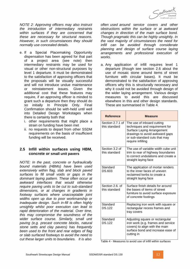
a. Any application of infill requires level 1 departure (though see section 2.6 about the use of mosaic stone around items of street furniture with circular bases). It must be demonstrated to the satisfaction of approving officers why this is structurally necessary and why it could not be avoided through design of the wider laying arrangement. Various design measures to avoid this are discussed elsewhere in this and other design standards. These are summarised in Table 4.
Reference
Measure
Section 2.7.1 of this standard
The use of inboard cutting techniques and requirement for Surface Laying Arrangement drawings to avoid awkward gaps or sub-standard cuts that may require infilling
Section 3.2 of this standard
The use of variable width cube unit trim to rear of highway boundaries to correct undulations and create a straight laying face
Standard DS.603
The application of mortar renders to the inner faces of uneven reclaimed kerbs to create a straight laying face
Section 2.6. of this standard
Surface finish details for around the bases of items of street furniture to avoid surface exposure of concrete footings
Standard DS.122
Replacing iron work with square or rectangular recess frames and tray covers
Standard DS.122
Adjusting square or rectangular iron work (e.g. frames and service covers) to align with the main surface bond and increase ease of cutting in
Table 4 - Measures to avoid use of infill within surfaces
Southwark Streetscape Design Manual SSDM/DSR standard DS.130 13
2.6 Detailing around bases of items of street furniture
a. If items of street furniture have a square or
rectangular base then requirements for detailing around the base of those items are as follows. i. Modular unit surfaced pavements
The modular units should be cut in directly up to the edges of the item (maintaining the required joint width). However, if orientating the item at an acute angle to the bonding pattern is unavoidable for some reason then a granite mosaic concealed surround detail may be permitted by level 1 departure (see note 1) – though see also note 2
ii. Bituminous mixture surfaced (and other non-modular) pavements If the neighbouring pavement surface is also being relayed then the new surface course should be laid right up to the item base. However, if this is not the case and the item is being installed into an existing retained surface then a granite mosaic concealed surround detail Type E (see note 1). Reinstatement of a bituminous mixture surface right up to the edge of the item then requires level 1 departure. This is only likely to be consented if either
the item is being installed in a location where the effective passing width for pedestrians (see standard DS.208) will be constrained and there is a consequent need to maximise the width of the accessible surface
the required design of the surround is such that an excessive width of mosaic surfacing would be necessary to any side of the item (e.g. >225mm).
NOTE 1: Where granite mosaic concealed surround details are used then care must be taken to ensure that the mosaic cover is of even balanced width to all sides of the item. Some relaxation of this principle is acceptable where positioning of items close to kerbs or other edge restraints is unavoidable such that it is not realistic to include a normal paving
unit of appropriate dimensions (or other non-modular surface) between the edge of the mosaic cover and the restraint. In more visible locations, designers should take care to position items appropriately to avoid such circumstances arising. However, this is less of a concern where items are positioned against walls to the rear of footway where the detail is likely to be less visible.
NOTE 2: If a significant number of items within the street use a granite mosaic detail (this being typically required for circular or elliptical based items in modular unit surfaced pavements) then, for the sake of visual consistency, approving officers may instruct the use of this detail to square or rectangular based items too. Designers may also request approval to use granite mosaic details for this same reason by level 1 departure.
b. If items of street furniture have a circular or elliptical base then requirements for detailing around the bases of those items are as follows. i. Modular unit surfaced pavements A granite mosaic concealed surround detail should be used (see note 1 to ‘a’). Use of any alternative detail requires level 1 departure ii. Bituminous mixture surfaced (and other non-modular) pavements As ‘a.ii’.
2.7 General laying requirements and guidance for modular unit surfaced pavements
2.7.1 Surface laying arrangement drawings
NOTE: Surface Laying Arrangement drawings detail out on a module by module basis the arrangement of modular unit surfaces and kerbs, including any cuts to these. They are typically used or required for prestige schemes and locations where a high quality finish is required and/or places where complex levels must be negotiated. Minimising cuts to units and achieving appropriate joints is important in both instances. Satisfactory results are unlikely to be achieved if this is left to paving gangs to work out on site.
a. if a project is within
Southwark Streetscape Design Manual SSDM/DSR standard DS.130 14
i. the World Centre, Town Centre or Heritage SSDM Specification Areas then a full Surface Laying Arrangement drawing providing detailed modular paving arrangements for all parts of the project area should be included as part of Design Proposal Information submissions in Detailed Design. Approving Officers also have discretion to require the same in other SSDM area designations for parts of project areas for which Special Placemaking Opportunity dispensations have been agreed
ii. If a project is within a General, Docks or Village SSDM Specification Area, then for any locations within the project area where there are:
changes in direction of the same modular paving bond
changes in levels
close groupings of service covers and/or items of street furniture
any other circumstances or features that might reasonably be foreseen as requiring complex cuts, in-board cutting techniques (see note) and or adaptation of general bonding patterns for modular unit surfaces in order to obtain visually and structurally acceptable results,
local detailed modular paving arrangements for those areas should be provided in a Surface Laying Arrangement drawing. This should be included as part of Design Proposal Information Submissions in the Detailed Design.
NOTE: Inboard cutting involves local variation of the paving bond pattern to avoid having to cut paving units to unacceptably small sizes. For instance, where 600x600 flags are being and a width of 700mm remains to a man hole cover, laying one uncut unit and one cut unit in this space would result in the latter having a width of only 100mm. The 100mm wide unit would be an unacceptable defect as per BS 7533-7 requirements (see section 2.7.1.). Cutting both units so that they are each 350mm wide (an acceptable width) would avoid this, alternatively adjust the bonding pattern at a greater distance to avoid the awkward distance.
b. Any instances other than as shown on approved Surface Laying Arrangement drawings of on-site in-board cutting (see note to ‘a’’) or sub-standard cuts not meeting BS 7533 requirements (see section 2.7.1) requires level 1 departure from the approving officer. They have discretion to require revision and re-approval of Surface Laying Arrangement drawings instead if they consider that the changes merit it. If such cuts or modifications are introduced without such approval then this is at the contractor’s risk and those instances may be identified as defects for correction at their expense.
2.7.2 Observance of British Standard codes of practice
a. Except for any varying requirements stated in this design standard (or in standards DS.601-603) all modular surface courses and edge restraints should be designed and laid in accordance with the requirements of the following British Standard codes of practice.
i. Pavements of precast concrete flags or natural stone slabs - BS 7533-7
ii. Pavements of natural stone paving units and cobbles, and rigid construction with concrete block paving - BS 7533-4:2006
iii. Pavement of precast concrete paving blocks and clay pavers for flexible pavements – BS 7533-3
iv. Rigid pavements of clay pavers – BS 7533-9.
NOTE 1: Designers and construction workers should pay close attention to requirements in the above standards for cutting of modular units.
NOTE 2: Designers and contractors are directed to section 2.12 of standard DS.601 for important requirements about compaction methods and the machinery that should be used for installation of unbound modular unit surfaces. This is of utmost importance to successful installation.
2.7.3 Use of edging frames to boundaries with edge restraints
NOTE: Edging frames typically consist of a single row of the same unit that is being used to the general surface, albeit laid abutting and parallel to the edge restraints to that surface in either a stretcher or solider course. These details introduce visual complexity into surfaces.
Southwark Streetscape Design Manual SSDM/DSR standard DS.130 15
However, they can occasionally provide pragmatic solutions to laying/maintenance issues.
a. Edging frames (see note above) should not be provided at the edge of areas of paving (though see section 3.2. regarding details to rear of footway boundaries). Except where permitted in other standards, use requires level 1 departure.
2.7.4 Number of packs to be used when laying
a. Modular units should always be laid from a minimum of 3 packs in order to avoid pronounced veining in laid surfaces and achieve an even distribution of shades. Laying from a lesser number of packs requires level 1 departure.
2.7.5 Consideration of movement joints
a. If underlying pavement courses include movement or warping joints (often required where pavement quality concrete base courses are present) then those joints must run vertically through to the surface of the pavement (see note). Consequently, their location must be anticipated in the design of the laying pattern for the surface course, with a view to ensuring that they align as far as possible with joints proposed for visual and bonding purposes alone.
NOTE: This requirement does not apply to HBM base course layers or (where there is no base course) upper subbase layers that have been pre-cracked and sealed - only to expansion, contraction and warping joints.
b. The above is often more complex than may at first seem apparent. Typically, in order to avoid unacceptable visual disruption of the laying pattern some iterative adjustment of both this and the proposed location of the movement and warping joints in the base course will be necessary. In some instances it may be possible to increase the necessary joint spacing by using thicker surface units or by increasing the thickness or other properties of the concrete base slab. This underlines both the importance of both
i. integrated structural and visual design ii. ensuring laying patterns are substantially
resolved by designers in approved drawings, and not simply left to be sorted out on site during construction works
Further discussion about design and spacing of movement joints can be found in standard DS.601.
3. Specific further requirements for footways and other non-carriageway pavements
3.1 Laying patterns for modular unit surfaced pavements
a. Regardless of whether paving units are flags,
slabs, blocks, pavers or setts (other than cube plan blocks or setts, for which see ‘b’) all units to the main footway surface should be laid in a stretcher bond. This should be set perpendicular to the dominant edge of the carriageway. Care should be taken to avoid or minimise cuts to units laid to the edge of carriageway kerb as this will undermine their breaking load in a location where they will be prone to vehicle overrun.
b. If cube plan blocks or setts are used then i. if the surface course is bound with mortar,
a stack bond should be ii. if the surface course is unbound (e.g. uses
a crushed rock or sand laying course and joints), an arch bond should be used (though see note).
NOTE: If precast concrete or clay units are preferred, use of cubes should generally be avoided as it normally necessitates the use of mortar. If designers wish to achieve a stack bond effect then special versions of standard rectangular blocks that have a groove in their upper face to create the impression of two cubes should be used instead. A stack bond can then be created using a standard stagger bond or herringbone bond. SSDM surfacing material palette include a number of such items.

Southwark Streetscape Design Manual SSDM/DSR standard DS.130 16
c. If a Special Placemaking Opportunity dispensation has been agreed for that part of a project area then alternative laying patterns to those specified as ‘a’ or ‘b’ may be used subject to level 1 departure.. It must be demonstrated to the satisfaction of Approving officers that the proposed alternatives will be both visually successful and structurally appropriate given the likely traffic conditions and possibility of vehicular overrun.
3.2 Boundary details 3.2.1. To rear of footway
a. Table 5 explains the different details that should be used to the rear of non-carriageway pavements where they abut private land (including areas of highway that are not adopted by the Highway Authority).
Circumstance
Detail to be used as SSDM drawing
LBS/1100/01-07
A
Boundary with private hard standing that has identical surface to the interfacing highway
Where both pavements use a bound modular construction
Type I metal stud detail
Where one or both pavements use unbound modular constructions
Type G2 metal angle detail
Where both pavement are bituminous mixture surfaced
B
Boundary with private hard standing of differing surface appearance to the interfacing Highway
Type F3 edging kerb detail
C
Boundary with wall or other vertical structure
Type H modular cube trim detail (see notes 1 and 2)
D
Boundary with private driveway or other area of vehicle standing
Type C2 flush full section kerb detail
E
Boundary with private garden or other area of municipal soft landscaping at the Highway limits (see note 3) that does not require a raised edge treatment
Type F1
NOTES 1) Rectangular plan units that have a sub-division in their face to make them appear as cubes may also
be used. 2) The typical width of trim to this detail is normally 2 rows. However, this may be locally increased by ±
half a row in order to retain a straight and even laying face for the dominant footway surface. Where very brief or awkward undulations exist then, subject to level 1 departure, an even greater number of rows may be used to fill this.
3) This Table does not apply to boundaries with tree pits and other soft landscaped areas that are within the highway (for which see section 3.2.3) – only those that are outside the Highway.
Table 5 - Rear edge details for footways and other non-carriageway pavements
Southwark Streetscape Design Manual SSDM/DSR standard DS.130 17
3.2.2. To front of footway
a. Except if permitted in other design standards, margins should not be introduced along the front edges of footways (and other non-carriageway pavements) that differ in appearance to the main footway surface - irrespective of their width (see note). Examples include in-situ concrete and/or precast concrete block paved margins to otherwise slab or flag surfaced footways. If the reason for considering such details is a concern
about excessive vehicle overrun then (subject to any necessary departures) the pavement construction should be strengthened instead in accordance with standard DS.601 so that the same surfacing can be used to its full width. If existing instances of such margins are encountered within a project area they should be removed. Retaining them requires level 1 departure.
3.2.3. Within footways
a. See standard DS.501 about edging requirements for tree pits and planting beds that are located within footways/verges etc. that form part of the Highway.
b. Where transitions occur between different sections of pavement along a footway (e.g. from flag or slab surfaced into modular block or bituminous mixture surfaced) then a concealed restraint should normally be used (see note).
NOTE: If one of the interfacing modular pavements uses a bound construction then a separate restraint is typically unlikely to be required since the edge of that that pavement alone ought to provide sufficient restraint to the other.
3.2.4. Where footways lead into unadopted areas
a. If a footway or cycleway leads into an area that is not adopted and maintained at public expense by the Highway Authority then a suitable boundary detail should be provided to clearly delineate the extents of the publicly adopted and
maintained Highway. That used will be agreed on a case specific basis with approving officers who have discretion to instruct whichever they deem appropriate. However, in all instances this must provide appropriate structural restraint to the Highway footway to limit any disturbance of this in the event of works within the unadopted area.
3.2.5. Land ownership boundaries
a. Land ownership boundaries should not be delineated on the Highway (see note 1). Any existing such features encountered within a project area should be removed (see note 2). Retaining these requires level 1 departure. It must be demonstrated that this is either of conservation value else that it performs a structural role that could not reasonably be designed out.
NOTE 1: Land ownership boundaries are as distinct from boundaries within the Highway delineating areas that are maintained at the public expense (e.g. adopted/vested in the Highway Authority) from those that are privately maintained. It is important to appreciate that designation of an area as a Highway is irrespective of land ownership.
NOTE 2: In particular metal stud and brass strip marking should only be used to delineate the limits of adopted areas of the Highway.
3.3. Surface channels in footways
a. Introducing surface channels in footways is to be avoided wherever possible by careful attention to grading (see standard DS.118 for further discussion). However, if this is unavoidable then i. to ensure good visual integration of the
detail
it should be composed of the same material as used to the neighbouring footways (and/or Build Out where present) to visually match both of these
the bond should be aligned to match that used to the neighbouring footway surfaces. In particular, transverse joints across the pavement should be aligned so that they continue without uninterrupted from, through and between the neighbouring surfaces. Minor variations on this may be
Southwark Streetscape Design Manual SSDM/DSR standard DS.130 18
permitted by level 1 departure. It must be demonstrated to the satisfaction of approving officers that the full requirements cannot reasonably be met without excessive cutting of units (e.g. cutting individual units to more than 1 side)
they should have a flat surface and a surface width of 250-300mm (though see note 1). Units should be cut where necessary to achieve this.
NOTE 1: V profile units may also be used if the gradient of the v is not steeper than 1:20 to either side. However, these must be complimentary special units from the same product range as the material used for the main footway/footpath surfacing that achieve a direct visual match with it. Where such units are used then the width of the channel may be greater than the value given in ‘3.3.a.ii’ (third bullet).
NOTE 2: See standard DS.118 about the potential use of existing kerbs as surface channels where Build Outs are added to existing footways. Broadly, this is not acceptable. In the interests of good visual integration they must normally broken out and replaced with a surface channel detail in accordance the above requirements.
4. Specific further requirements for carriageway pavements
4.1 Extent of modular unit surfaced areas within carriageways
a. Except within the Docks SSDM Specification Area (see note 1) modular unit paved areas should typically only be introduced i. at junctions ii. at Formal Crossing Points iii. to parking bays (including Inset
Parking Bays) iv. where carriageways pass through
public spaces They should not make up greater than 50% of the surface area of the carriageway to the length of a given street or space (measured junction to junction). Greater areas of modular unit paved surfacing may be permitted but requires
level 1 departure, whilst the Highway Authority also reserves to right to require commuted sums.
NOTE 1: In this particular Specification Area comprehensive paving of carriageways has historically been common place.
NOTE 2: The suitability of introducing modular unit paving to carriageways will depend upon the level and nature of trafficking by heavier vehicles. It will not be suitable in all instances. See standard DS.601 for further information.
4.2 Modular unit types and laying patterns
4.2.1 Unbound modular surfaces
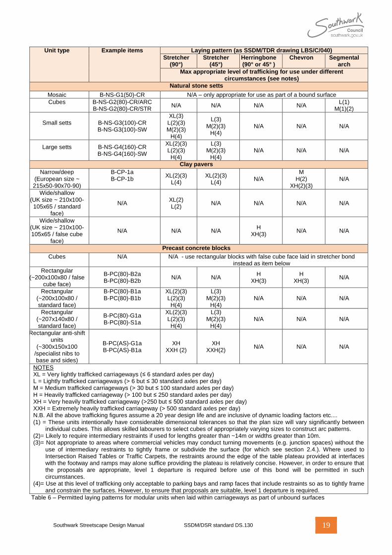
a. TableTable 6 6 explains which permitted laying patterns for modular unit paved surfaces may be used to carriageway pavements for different types of units in different traffic situations where the surface is unbound (see note).
4.2.2 Bound modular surfaces
a. Where use of bound modular surfaces is permitted (see standard DS.601) laying patterns will be agreed with approving officers on a case specific basis.
NOTE: Typically a 90° stretcher bond is likely to be most appropriate for rectangular plan units and a stack or segmental arc bond for cubes. .
4.3 Boundary features where carriageways lead into unadopted areas
a. A boundary detail should always be provided
where publically adopted and maintained Highways transition into privately maintained (e.g. unadopted) Highway carriageways or other privately maintained Roads. This must provide full and effective restraint to the Highway carriageway in the event of any works to the unadopted carriageway pavements However approving officers have discretion to instruct the use of other details where they consider it appropriate owing to the nature of the Highway pavement construction and/or the levels of likely vehicle trafficking.
Southwark Streetscape Design Manual SSDM/DSR standard DS.130 19
Unit type
Example items
Laying pattern (as SSDM/TDR drawing LBS/C/040)
Stretcher (90°)
Stretcher (45°)
Herringbone (90° or 45° )
Chevron Segmental arch
Max appropriate level of trafficking for use under different circumstances (see notes)
Natural stone setts
Mosaic B-NS-G1(50)-CR N/A – only appropriate for use as part of a bound surface
Cubes
B-NS-G2(80)-CR/ARC B-NS-G2(80)-CR/STR
N/A N/A N/A N/A L(1)
M(1)(2)
Small setts
B-NS-G3(100)-CR B-NS-G3(100)-SW
XL(3) L(2)(3) M(2)(3)
H(4)
L(3) M(2)(3)
H(4) N/A N/A N/A
Large setts
B-NS-G4(160)-CR B-NS-G4(160)-SW
XL(2)(3) L(2)(3) H(4)
L(3) M(2)(3)
H(4) N/A N/A N/A
Clay pavers
Narrow/deep (European size ~ 215x50-90x70-90)
B-CP-1a B-CP-1b
XL(2)(3) L(4)
XL(2)(3) L(4)
N/A M
H(2) XH(2)(3)
N/A
Wide/shallow (UK size ~ 210x100-105x65 / standard
face)
N/A XL(2) L(2)
N/A N/A N/A N/A
Wide/shallow (UK size ~ 210x100-105x65 / false cube
face)
N/A N/A N/A H
XH(3) N/A N/A
Precast concrete blocks
Cubes
N/A
N/A - use rectangular blocks with false cube face laid in stretcher bond instead as item below
Rectangular (~200x100x80 / false
cube face)
B-PC(80)-B2a B-PC(80)-B2b
N/A N/A H
XH(3) H
XH(3) N/A
Rectangular (~200x100x80 / standard face)
B-PC(80)-B1a B-PC(80)-B1b
XL(2)(3) L(2)(3) H(4)
L(3) M(2)(3)
H(4) N/A N/A N/A
Rectangular (~207x140x80 / standard face)
B-PC(80)-G1a B-PC(80)-S1a
XL(2)(3) L(2)(3) H(4)
L(3) M(2)(3)
H(4) N/A N/A N/A
Rectangular anti-shift units
(~300x150x100 /specialist nibs to base and sides)
B-PC(AS)-G1a B-PC(AS)-B1a
XH XXH (2)
XH XXH(2)
N/A N/A N/A
NOTES XL = Very lightly trafficked carriageways (≤ 6 standard axles per day) L = Lightly trafficked carriageways (> 6 but ≤ 30 standard axles per day) M = Medium trafficked carriageways (> 30 but ≤ 100 standard axles per day) H = Heavily trafficked carriageway (> 100 but ≤ 250 standard axles per day) XH = Very heavily trafficked carriageway (>250 but ≤ 500 standard axles per day) XXH = Extremely heavily trafficked carriageway (> 500 standard axles per day) N.B. All the above trafficking figures assume a 20 year design life and are inclusive of dynamic loading factors etc.... (1) = These units intentionally have considerable dimensional tolerances so that the plan size will vary significantly between
individual cubes. This allows skilled labourers to select cubes of appropriately varying sizes to construct arc patterns. (2)= Likely to require intermediary restraints if used for lengths greater than ~14m or widths greater than 10m. (3)= Not appropriate to areas where commercial vehicles may conduct turning movements (e.g. junction spaces) without the
use of intermediary restraints to tightly frame or subdivide the surface (for which see section 2.4.). Where used to Intersection Raised Tables or Traffic Carpets, the restraints around the edge of the table plateau provided at interfaces with the footway and ramps may alone suffice providing the plateau is relatively concise. However, in order to ensure that the proposals are appropriate, level 1 departure is required before use of this bond will be permitted in such circumstances.
(4)= Use at this level of trafficking only acceptable to parking bays and ramp faces that include restraints so as to tightly frame and constrain the surfaces. However, to ensure that proposals are suitable, level 1 departure is required.
Table 6 – Permitted laying patterns for modular units when laid within carriageways as part of unbound surfaces
Southwark Streetscape Design Manual SSDM/DSR standard DS.130 20
Appendix A – Detailed requirements for the number of materials that may be used to Principle Surface Zones in different Specification Areas
NOTE: See section 2 of the main design standard for further information about Principle Surface Zones
A.1 General Specification Area
a. Except for locations within a project area for which a Special Placemaking Opportunity dispensation has agreed, the total number of materials used to Principle Surface Zones across all pavements should not exceed 3. Typically these are likely to be used as follows. i. A bituminous mixture surfaced
carriageway ii. A single type of precast concrete flag
paving unit to footways (including the plateaus of Vehicle Crossings)
iii. A single type of precast concrete block or clay paver to Raised Tables, Traffic Carpets and Inset Parking Bays within the carriageway. These may also be used to the plateaus of Vehicle Crossings where the level of trafficking would not permit these to be surfaced with the same material as ‘ii’ and to and to any Cycle tracks if these are provided.
A.2 Docks Specification Area
a. Except for locations within a project area for which a Special Placemaking Opportunity dispensation has agreed, the total number of materials used to Principle Surface Zones across all pavements should not exceed three. Typically these are likely to be used as follows. i. A bituminous mixture or small modular
paving unit surfaced carriageway (see note)
ii. A single type of clay paver unit to footways (including the plateaus of Vehicle Crossings)
iii. A single type of precast concrete block or clay paver to Raised Tables, Traffic Carpets and Inset Parking Bays within the carriageway. These may also be used to the plateaus of Vehicle Crossings where the level of trafficking would not permit these to be surfaced with the same material as ‘ii’ and to and to any Cycle tracks if these are provided.
NOTE: Carriageways in this part of the borough have historically been surfaced with modular paving units.
A.3 Village Specification Area
a. Except for locations within a project area for which a Special Placemaking Opportunity dispensation has been agreed, the total number of materials used to Principle Surface Zones across all pavements should not exceed three. Typically these are likely to be used as follows.
i. A bituminous mixture surfaced carriageway ii. A bituminous mixture or single type of
precast concrete flag surface to footways (including the plateaus of Vehicle Crossings)
iii. A single type of precast concrete block or clay paver to Raised Tables, Traffic Carpets and Inset Parking Bays within the carriageway. These may also be used to the plateaus of Vehicle Crossings where the level of trafficking would not permit these to be surfaced with the same material as ‘ii’ and to and to any Cycle tracks if these are provided.
NOTE: In this Specification Area delineation of footways from carriageways relies significantly on the presence of grass verges at the front of footway else (in the absence of these) the combined visual effect of kerb and channel details.
A.4 Town centre Specification Area
a. Except for locations within a project area for which a Special Placemaking Opportunity dispensation has been agreed, the total
Southwark Streetscape Design Manual SSDM/DSR standard DS.130 21
number of materials used to Principle Surface Zones across all pavements should not exceed four. Typically these are likely to be used as follows.
i. A bituminous mixture and/or small modular paving unit surfaced carriageway
ii. A single type of large precast concrete flag or natural stone slab paving unit to footways (including the plateaus of Vehicle Crossings)
iii. One or more types of precast concrete block or clay paver to Raised Tables, Traffic Carpets and Inset Parking Bays within the carriageway. These may also be used to the plateaus of Vehicle Crossings where the level of trafficking would not permit these to be surfaced with the same material as ‘ii’ and to and to any Cycle tracks if these are provided.
A.5 Heritage Specification Area
a. Except for locations within a project area for which a Special Placemaking Opportunity dispensation has been agreed, the total number of materials used to Principle Surface Zones across all pavements should not exceed three. Typically these are likely to be used as follows.
i. A bituminous mixture surfaced carriageway
ii. A single type of large natural stone slab paving unit to footways (including the plateaus of Vehicle Crossings)
iii. A single type of precast concrete block or clay paver to Raised Tables, Traffic Carpets and Inset Parking Bays within the carriageway. These may also be used to the plateaus of Vehicle Crossings where the level of trafficking would not permit these to be surfaced with the same material as ‘ii’ and to and to any Cycle tracks if these are provided.
A.6 World centre Specification
a. Except for locations within a project area for which a Special Placemaking Opportunity dispensation has been agreed, the total number of materials used to Principle Surface Zones across all pavements should not exceed four. Typically these are likely to be used as follows. i. A bituminous mixture and/or natural stone
sett surfaced carriageway ii. A single type of large natural stone slab
paving unit to footways (including the plateaus of Vehicle Crossings)
iii. One or more types of precast concrete block or clay paver to Raised Tables, Traffic Carpets and Inset Parking Bays within the carriageway. These may also be used to the plateaus of Vehicle Crossings where the level of trafficking would not permit these to be surfaced with the same material as ‘ii’ and to and to any Cycle tracks if these are provided.
Southwark Streetscape Design Manual SSDM/DSR standard DS.130 22
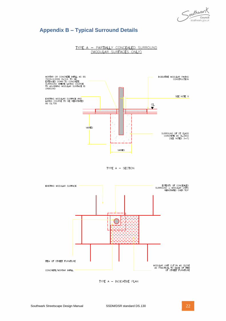
Appendix B – Typical Surround Details
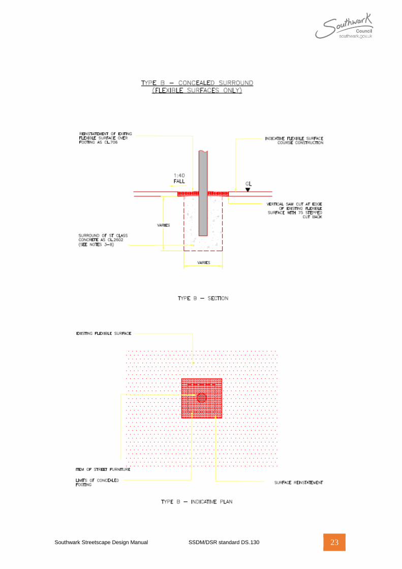
Southwark Streetscape Design Manual SSDM/DSR standard DS.130 23
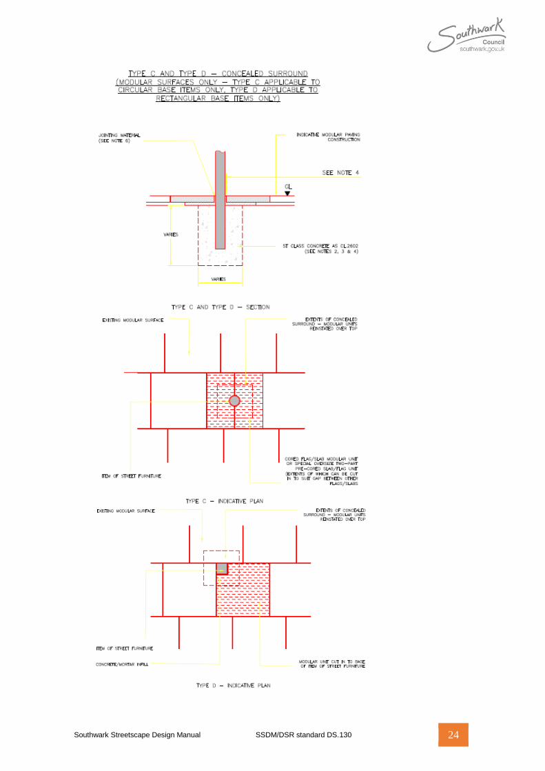
Southwark Streetscape Design Manual SSDM/DSR standard DS.130 24
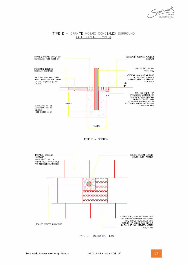
Southwark Streetscape Design Manual SSDM/DSR standard DS.130 25
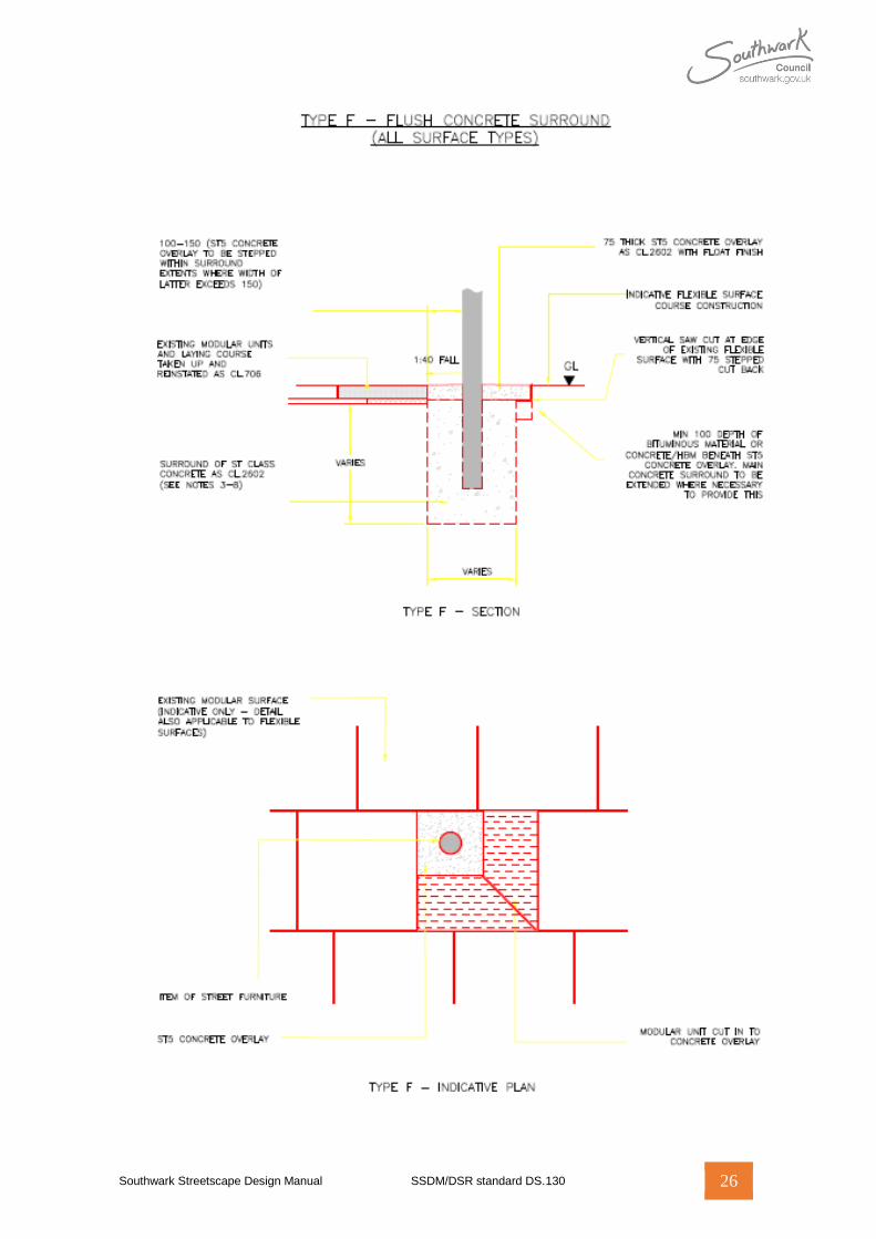
Southwark Streetscape Design Manual SSDM/DSR standard DS.130 26