drylin r linear plain bearing - igus® inc. · drylin® r linear plain bearing ... 20 20.000/19.988...
TRANSCRIPT

Inte
rnet
: h
ttp
://w
ww
.igu
s.co
mE
-Mai
l: sa
les@
igu
s.co
mQ
uic
kSp
ec:
ww
w.ig
us.
com
/qs/
Dry
Lin
.asp
Tele
ph
on
e1-
888-
803-
1895
Fax
1-
401-
438-
7680
Dry
Lin
®R
Lin
ear
Bea
rin
gs
24.2
DryLin® R Linear Plain Bearing
+194°
–40°F
+482°F
–148°F
iglide® J iglide® T500iglide® J200
DryLin® R can be used inextreme dirt conditions
DryLin® R can be used inhigh tem pe rature environ -ments
DryLin® R can be used forapplica tions with aggres s ivechemicals
Technical DataLiners: Maintenance-free
Materials:
iglide® J
iglide® J200
iglide® T500
Max. speed: up to 15 ft/s
Shaft materials:
Anodized aluminum
Case-hardened steel
Stainless steel
Cold-rolled steel
Hard chrome-plated
carbon fibre
Advantages of DryLin® RSelf-lubricating
Maintenance-free
Can be used in extreme dirt conditions
Can be used underwater or in washdown
condi tions
Replaceable liner
Dimensionally interchangeable with standard
recirculating ball bearings
Vibration dampening
No seals or wipers needed
Compensation for shaft misalignment (03 series)
DryLin® R linear plain bearings, made from solid polymers, are dimensionally equivalent to standard ball bearings. They are made entirely of wear resistant iglide® materials and offer technical advantages as well as a clear price advantage.
DryLin® R: Linear Plain BearingsDryLin® R is dimensionally interchangeable with linear ball bearings, but offers cleaner, more cost-effectiveresults even in harsh environments. The standard RJUI/RJUM bearing consists of an iglide® J liner slip-fitinto an aluminum housing. The unique grooved design of the J liner minimizes clearance, is suitable foruse in extremely wet and dirty environments, and is easily replaceable. Dimensionally interchangeable all-polymer parts RJI/RJM are also available for cost-savings, weight reduction, and other technical advantages.Both parts are secured with retaining clips, as are ball bearings. DryLin R guides may also be used withthe high temperature, chemically resistant TUI/TUM liners for extreme applications.
6
6
Self aligning adapter aluminum anodized
Stainless steel adapter (optional)
Standard flanged housing anodized aluminum
Standard iglide® J liner
High temperature iglide® T500 liner
Pillow blocks - dimensionally interchangeable with ball bearings

General Properties Unit iglide® J iglide® T500 iglide® J200 Testing Method(Available in
some sizes)
Density g/cm3 1.49 1.44 1.72
Color Yellow Black Dark grey
Max. moisture absorption at 23 °C/50% r. F. % weight 0.3 0.1 0.2 DIN 53495
Max. moisture absorption at 73°F % weight 1.3 0.5 0.7
Coefficient of sliding friction. dynamic against steel µ 0.06 - 0.18 0.09 - 0.27 0.11- 0.17
P x V value. max. (dry) psi x fpm 9,700 37,700 8,600
Mechanical Properties
Modulus of elasticity PSI 398,090 1,174,806 406,105 DIN 53457
Tensile strength at 68°F PSI 10587 24656 8412 DIN 53452
Compressive strength PSI 8702 14504 n.d.
Permissible static surface pressure (68°F) PSI 5076 21755 3335
Shore D hardness 74 85 70 DIN 53505
Physical and Thermal Properties
Max. long term application temperature °F 194 482 194
Max. short term application temperature °F 248 599 248
Min. application temperature °F -58 -148 -58
Thermal conductivity W/m x K 0.25 0.6 0.24 ASTM C 177
Coefficient of thermal expansion (at 68°C) K-1 x 10 -5 10 5 8 DIN 53752
Electrical Properties
Specific volume resistance Ωcm > 1013 < 105 > 108 DIN IEC 93
Surface resistance Ω > 1012 < 103 > 108 DIN 53482
inch
mm
PD
F:
ww
w.ig
us.
com
/pd
f/D
ryL
in.a
spS
pec
s/C
AD
/RF
Q:
ww
w.ig
us.
com
/Dry
Lin
R.a
spR
oH
S in
fo:
ww
w.ig
us.
com
/Ro
HS
.asp
Dry
Lin
®R
Lin
ear
Bea
rin
gs
24.3
DryLin® R Linear Plain BearingMaterial Table
01
001
0001
1.0 1 01
)ces / tf( v deepS
Lo
ad /
Sh
aft
Siz
e (l
bs
/ in
ch)
Graph 24.1: DryLin® R – Comparison of the permissible dynamic loads at equivalent diameters
Cantilevered shaft –steel/stainless steel
Cantilevered shaft – hard anodized aluminium
Supported shaft –steel/stainless steel
Supported shaft – hard anodized aluminium
Table 24.1: Material Data
Inte
rnet
: h
ttp
://w
ww
.igu
s.co
mE
-Mai
l: sa
les@
igu
s.co
mQ
uic
kSp
ec:
ww
w.ig
us.
com
/qs/
Dry
Lin
.asp
Tele
ph
on
e1-
888-
803-
1895
Fax
1-
401-
438-
7680
Dry
Lin
®R
Lin
ear
Bea
rin
gs
24.4
Shaft Materials and DryLin® R Linear Plain Bearings
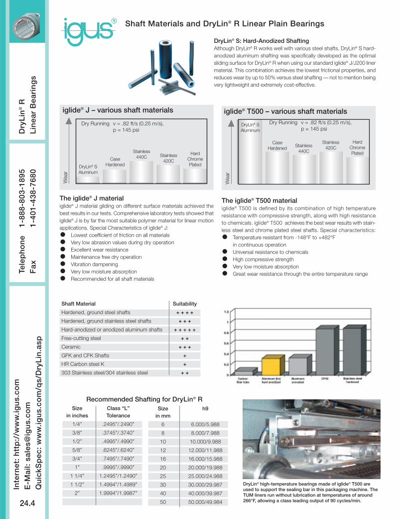
DryLin® S: Hard-Anodized ShaftingAlthough DryLin® R works well with various steel shafts, DryLin® S hard-anodized aluminum shafting was specifically developed as the optimalsliding surface for DryLin® R when using our standard iglide® J/J200 linermaterial. This combination achieves the lowest frictional properties, andreduces wear by up to 50% versus steel shafting — not to mention beingvery lightweight and extremely cost-effective.
The iglide® T500 materialiglide® T500 is defined by its combination of high temperatureresistance with compressive strength, along with high resistanceto chemicals. iglide® T500 achieves the best wear results with stain-less steel and chrome plated steel shafts. Special characteristics:
Temperature resistant from -148°F to +482°Fin continuous operationUniversal resistance to chemicalsHigh compressive strengthVery low moisture absorption Great wear resistance through the entire temperature range
iglide® T500 – various shaft materials
Wea
r
Dry Running v = .82 ft/s (0.25 m/s), p = 145 psi
DryLin® SAluminum
CaseHardened Stainless
440C
Stainless420C
HardChromePlated
The iglide® J materialiglide® J material gliding on different surface materials achieved thebest results in our tests. Comprehensive laboratory tests showed thatiglide® J is by far the most suitable polymer material for linear motionapplications. Special Characteristics of iglide® J:
Lowest coefficient of friction on all materialsVery low abrasion values during dry operationExcellent wear resistanceMaintenance free dry operationVibration dampening Very low moisture absorptionRecommended for all shaft materials
iglide® J – various shaft materials
Wea
r
Dry Running v = .82 ft/s (0.25 m/s), p = 145 psi
DryLin® SAluminum
CaseHardened
Stainless440C Stainless
420C
HardChromePlated
Recommended Shafting for DryLin® RSize Class “L”
in inches Tolerance
1/4” .2495”/.2490”
3/8” .3745”/.3740”
1/2” .4995”/.4990”
5/8” .6245”/.6240”
3/4” .7495”/.7490”
1” .9995”/.9990”
1 1/4” 1.2495”/1.2490”
1 1/2” 1.4994”/1.4989”
2” 1.9994”/1.9987”
Size h9in mm
6 6.000/5.988
8 8.000/7.988
10 10.000/9.988
12 12.000/11.988
16 16.000/15.988
20 20.000/19.988
25 25.000/24.988
30 30.000/29.987
40 40.000/39.987
50 50.000/49.984
Shaft Material Suitability
Hardened, ground steel shafts + + + +
Hardened, ground stainless steel shafts + + +
Hard-anodized or anodized aluminum shafts + + + + +
Free-cutting steel + +
Ceramic + + +
GFK and CFK Shafts +
HR Carbon steel K +
303 Stainless steel/304 stainless steel + +
DryLin® high-temperature bearings made of iglide® T500 areused to support the sealing bar in this packaging machine. TheTUM liners run without lubrication at temperatures of around266°F, allowing a class leading output of 90 cycles/min.
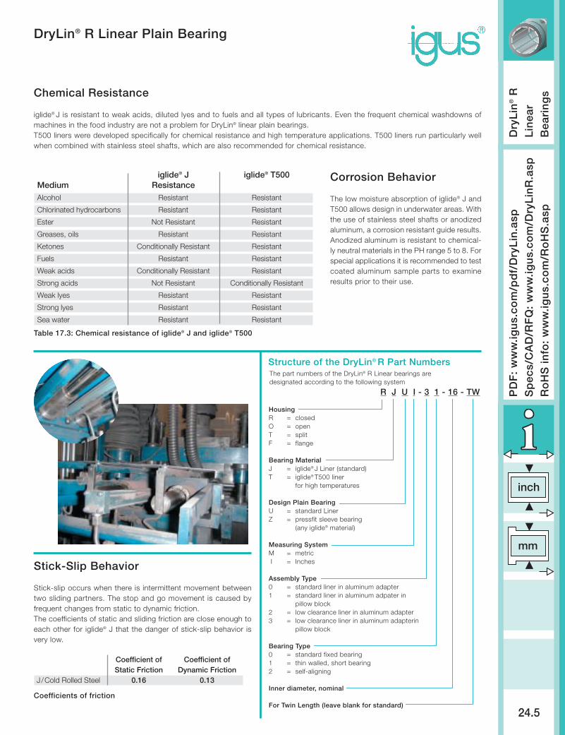
R J U I - 3 1 - 16 - TW
HousingR = closedO = openT = split F = flange
Bearing MaterialJ = iglide® J Liner (standard)T = iglide® T500 liner
for high temperatures
Design Plain BearingU = standard LinerZ = pressfit sleeve bearing
(any iglide® material)
Measuring SystemM = metricI = Inches
Assembly Type0 = standard liner in aluminum adapter1 = standard liner in aluminum adpater in
pillow block2 = low clearance liner in aluminum adapter3 = low clearance liner in aluminum adapterin
pillow block
Bearing Type0 = standard fixed bearing1 = thin walled, short bearing2 = self-aligning
Inner diameter, nominal
For Twin Length (leave blank for standard)
inch
mm
PD
F:
ww
w.ig
us.
com
/pd
f/D
ryL
in.a
spS
pec
s/C
AD
/RF
Q:
ww
w.ig
us.
com
/Dry
Lin
R.a
spR
oH
S in
fo:
ww
w.ig
us.
com
/Ro
HS
.asp
Dry
Lin
®R
Lin
ear
Bea
rin
gs
24.5
DryLin® R Linear Plain Bearing
Chemical Resistance
iglide® J is resistant to weak acids, diluted lyes and to fuels and all types of lubricants. Even the frequent chemical washdowns ofmachines in the food industry are not a problem for DryLin® linear plain bearings.T500 liners were developed specifically for chemical resistance and high temperature applications. T500 liners run particularly wellwhen combined with stainless steel shafts, which are also recommended for chemical resistance.
Corrosion Behavior
The low moisture absorption of iglide® J andT500 allows design in underwater areas. Withthe use of stainless steel shafts or anodizedaluminum, a corrosion resistant guide results.Anodized aluminum is resistant to chemical-ly neutral materials in the PH range 5 to 8. Forspecial applications it is recommended to testcoated aluminum sample parts to examineresults prior to their use.
Table 17.3: Chemical resistance of iglide® J and iglide® T500
iglide® J iglide® T500Medium ResistanceAlcohol Resistant Resistant
Chlorinated hydrocarbons Resistant Resistant
Ester Not Resistant Resistant
Greases, oils Resistant Resistant
Ketones Conditionally Resistant Resistant
Fuels Resistant Resistant
Weak acids Conditionally Resistant Resistant
Strong acids Not Resistant Conditionally Resistant
Weak lyes Resistant Resistant
Strong lyes Resistant Resistant
Sea water Resistant Resistant
Stick-Slip Behavior
Stick-slip occurs when there is intermittent movement betweentwo sliding partners. The stop and go movement is caused byfrequent changes from static to dynamic friction.The coefficients of static and sliding friction are close enough toeach other for iglide® J that the danger of stick-slip behavior isvery low.
Coefficients of friction
Coefficient of Coefficient ofStatic Friction Dynamic Friction
J/Cold Rolled Steel 0.16 0.13
Structure of the DryLin® R Part NumbersThe part numbers of the DryLin® R Linear bearings aredesignated according to the following system
Inte
rnet
: h
ttp
://w
ww
.igu
s.co
mE
-Mai
l: sa
les@
igu
s.co
mQ
uic
kSp
ec:
ww
w.ig
us.
com
/qs/
Dry
Lin
.asp
Tele
ph
on
e1-
888-
803-
1895
Fax
1-
401-
438-
7680
Dry
Lin
®R
Lin
ear
Bea
rin
gs
24.6
DryLin® R Linear Plain Bearing
Split Linear Bearings
The DryLin® liner can be pushed easily ontothe shaft
Then the adapter is fitted over the liner Installation is simple and reduces downtimeand maintenance costs
Applications that operate on the edge of technical feasibility or in extremely harsh environmentsare characterized by the frequent replacement of the linear bearings. In many cases, service life canbe multiplied many times by DryLin®. However, extreme applications, replacement of the bearingscan be necessary even with DryLin®.
DryLin® linear bearings can contribute to considerable cost reductions in such cases, as onlythe bearings liner made of plastics has to be replaced. This often means a reduction of more than90% in replacement part costs. The iglide® J liner can be replaced, while a ball-bearing cage cannot.
The new range of split adapters offers even greater cost savings. Shafts need no longer beremoved from the housing. The two shells of the adapter can be opened very easily. The high-performance plastic bearing inside is split and can easily be pulled off the shaft. Clip a new bearingover the shaft, put the two adapter halves together, install - done!
With this product line of split DryLin® bearings, installation times can be reduced to a minimum.
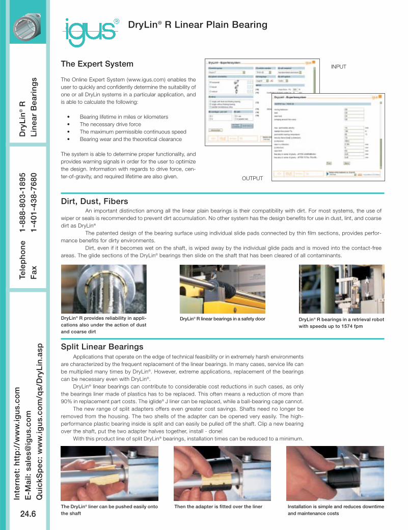
Dirt, Dust, FibersAn important distinction among all the linear plain bearings is their compatibility with dirt. For most systems, the use of
wiper or seals is recommended to prevent dirt accumulation. No other system has the design benefits for use in dust, lint, and coarsedirt as DryLin®
The patented design of the bearing surface using individual slide pads connected by thin film sections, provides perfor-mance benefits for dirty environments.
Dirt, even if it becomes wet on the shaft, is wiped away by the individual glide pads and is moved into the contact-freeareas. The glide sections of the DryLin® bearings then slide on the shaft that has been cleared of all contaminants.
DryLin® R provides reliability in appli-cations also under the action of dustand coarse dirt
DryLin® R linear bearings in a safety door DryLin® R bearings in a retrieval robotwith speeds up to 1574 fpm
The Expert System
The Online Expert System (www.igus.com) enables theuser to quickly and confidently determine the suitability ofone or all DryLin systems in a particular application, andis able to calculate the following:
• Bearing lifetime in miles or kilometers• The necessary drive force• The maximum permissible continuous speed• Bearing wear and the theoretical clearance
The system is able to determine proper functionality, andprovides warning signals in order for the user to optimizethe design. Information with regards to drive force, cen-ter-of-gravity, and required lifetime are also given.
INPUT
OUTPUT
inch
mm
PD
F:
ww
w.ig
us.
com
/pd
f/D
ryL
in.a
spS
pec
s/C
AD
/RF
Q:
ww
w.ig
us.
com
/Dry
Lin
R.a
spR
oH
S in
fo:
ww
w.ig
us.
com
/Ro
HS
.asp
Dry
Lin
®R
Lin
ear
Bea
rin
gs
24.7
DryLin® R Linear Plain Bearing
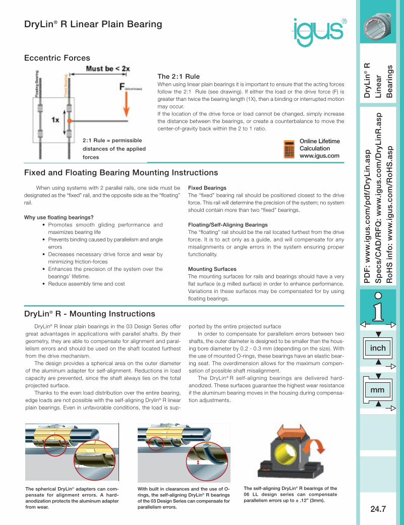
Eccentric Forces
2:1 Rule = permissible
distances of the applied
forces
Online LifetimeCalculationwww.igus.com
The 2 :1 RuleWhen using linear plain bearings it is important to ensure that the acting forcesfollow the 2:1 Rule (see drawing). If either the load or the drive force (F) isgreater than twice the bearing length (1X), then a binding or interrupted motionmay occur.If the location of the drive force or load cannot be changed, simply increasethe distance between the bearings, or create a counterbalance to move thecenter-of-gravity back within the 2 to 1 ratio.
DryLin® R linear plain bearings in the 03 Design Series offergreat advantages in applications with parallel shafts. By theirgeometry, they are able to compensate for alignment and paral-lelism errors and should be used on the shaft located furthestfrom the drive mechanism.
The design provides a spherical area on the outer diameterof the aluminum adapter for self-alignment. Reductions in loadcapacity are prevented, since the shaft always lies on the totalprojected surface.
Thanks to the even load distribution over the entire bearing,edge loads are not possible with the self-aligning Drylin® R linearplain bearings. Even in unfavorable conditions, the load is sup-
ported by the entire projected surfaceIn order to compensate for parallelism errors between two
shafts, the outer diameter is designed to be smaller than the hous-ing bore diameter by 0.2 - 0.3 mm (depending on the size). Withthe use of mounted O-rings, these bearings have an elastic bear-ing seat. The overdimension allows for the maximum compen-sation of possible shaft misalignment.
The DryLin® R self-aligning bearings are delivered hard-anodized. These surfaces guarantee the highest wear resistanceif the aluminum bearing moves in the housing during compensa-tion adjustments.
The spherical DryLin® adapters can com-pensate for alignment errors. A hard-anodization protects the aluminum adapterfrom wear.
With built in clearances and the use of O-rings, the self-aligning DryLin® R bearingsof the 03 Design Series can compensate forparallelism errors.
The self-aligning DryLin® R bearings of the06 LL design series can compensateparallelism errors up to ± .12” (3mm).
DryLin® R - Mounting Instructions
When using systems with 2 parallel rails, one side must bedesignated as the “fixed” rail, and the opposite side as the “floating”rail.
Why use floating bearings?• Promotes smooth gliding performance and
maximizes bearing life• Prevents binding caused by parallelism and angle
errors• Decreases necessary drive force and wear by
minimizing friction-forces• Enhances the precision of the system over the
bearings’ lifetime.• Reduce assembly time and cost
Fixed BearingsThe “fixed” bearing rail should be positioned closest to the driveforce. This rail will determine the precision of the system; no systemshould contain more than two “fixed” bearings.
Floating/Self-Aligning BearingsThe “floating” rail should be the rail located furthest from the driveforce. It is to act only as a guide, and will compensate for anymisalignments or angle errors in the system ensuring properfunctionality.
Mounting SurfacesThe mounting surfaces for rails and bearings should have a veryflat surface (e.g milled surface) in order to enhance performance.Variations in these surfaces may be compensated for by usingfloating bearings.
Fixed and Floating Bearing Mounting Instructions

Inte
rnet
: h
ttp
://w
ww
.igu
s.co
mE
-Mai
l: sa
les@
igu
s.co
mQ
uic
kSp
ec:
ww
w.ig
us.
com
/qs/
Dry
Lin
.asp
Tele
ph
on
e1-
888-
803-
1895
Fax
1-
401-
438-
7680
Dry
Lin
®R
Lin
ear
Bea
rin
gs
24.8
DryLin® R Linear Plain Bearing - Applications
This application, a rotary transfer machine, seals champagne bottles withcorks, aluminum caps and wire braid. The fact that the DryLin® guide systems arelubricant free is important in the food sector, additional benefits include resistanceto chemicals and cleaning.
This application from the food industry transfers breads and pastries from oneconveyor to the next. Lubrication is totally prohibited due to food contact. Anotherreason for using the DryLin® R linear plain bearings is the resistance to corrosivecleaning agents. Additional benefits include the reduced design space required bythe iglide® J bearings and the excellent corrosion resistance.