dry and semi-dry technologies - columbia … is the engineering company of the central austrian...
TRANSCRIPT

9th Annual North American Waste to Energy Conference
ASME 2001
NEW FGD DEVELOPMENTS IN EUROPE
Anthony Licata Dr. Wolfgang Schuettenhelm
Ryszard Kubisa Babcock Borsig Power, Inc.
INTRODUCTION
In Europe over the past 40 years there has been considerable social, regulatory, and economic pressures to manage solid waste in a manner that is beneficial to mankind. There have been many successful programs to minimize waste, recycle and reuse waste through energy conversion. As part of the energy conversion process strict air emissions emission standards have been adopted for waste-toenergy plants.
However, the latest trend in waste management has been to ban landfilling of municipal waste. In the smaller countries such as Austria this has resulted in an increase demand for waste-to-energy. The waste management practices in Germany and Holland are considerably different than those of the less densely populated countries such as Austria and Hungary. In Austria the waste-to-energy plants are smaller than most plants in Germany. As a result, the economics of air pollution control systems are considerably different.
Some waste-to-energy plants in Germany and Holland have used up to five independent stages of air cleaning to meet their contractual, recycling and land disposal requirements. This approach to air pollution control is not economically viable in most other countries. Austrian Energy, now part of the Babcock Borsig Power Group, began development of several dry and semi-dry FGD technologies that
. will meet the economic as well as the regulatory environmental criteria. One advancement has been in the development in air pollution control systems is the application of fluidized bed technology.
73
DRY AND SEMI-DRY TECHNOLOGIES
We would like· to distinguish the difference between "dry" scrubbing and dry additive injection into furnace process. New methods have emerged in the last decade including isolated moistening of absorbent (being a mixture of reaction products and fresh reactant), in such a way that it keeps the properties of dry powder (having not more than 12 mass % of water). This method mitigates sticking of . solids to apparatus walls and corrosion is minimized and the broad use of carbon steel in apparatus manufacturing made possible. Process regulation is much easier due to high recirculation ratios, the required costs involved with securing of high availability (obviously higher that energetic block itself) are also much lower than in the other technologies.
Such process is often incorrectly named "dry desulfurization", dry scrubbing or acid gas control i.e. just the same as in the literature is named process in which a sorbent - mostly limestone, undergoes temperature decomposition in the range of 1385 to 1655°F (750 - 900°C), and just formed CaO takes part in fixing of S02, S03, HCI, and HF. Such dry, high temperature desulfurization process, in its modification with additional moistening of particulate laded flue gases beyond boiler
In semi dry technologies that are mainly the subject of this presentation, binding of acid gases goes mostly in water solution according to the reactions:
Ca(OH)2 + S02
Ca(OH)2 + S03
� Caso3 * Y2 H20 + Y2 H20
� Caso4 * Y2 H20 + Y2 H20

Ca(OHh + c�
Ca(OH)2 + 2HCI
Ca(OH)2 + 2HF
=> CaCO) + H20
CaCh + 2 H20
=> CaF2 + 2 H20
Spraying of certain amount of water or water solution onto sorbent powder gives occasion to appear of tiny droplets of solution on the surface of reactant particles. In short "life time" of such droplet two main processes take place: water evaporation to gas phase having much higher temperature and in the same time lime dissolution and quick chemical reactions with acid components of gas. Particle surface temperature is then close to the temperature of adiabatic gas saturation. Product particle structure is stratified - "onion like", connected with multiple product recirculation, in contrast to dry scrubbing product having form of particles agglomerates of dried reaction products.
Actually have appeared some types of so called dry calcium desulfurization (acid gases) methods in which absorption takes place on the moistened surface of sorbent. Their common advantage is simple construction of reactor in which the main process of S02 bonding takes place as well as taking off desulfurization product in fOI In of powder separated from cleaned gas in conventional filtering equipment.
Turbosorp® process
Austrian Energy wanted to develop a "dry" technology that would work for a wide range of plants which was able to treat all the important flue gas pollutants like SOx, NOx, HCI, and HF as well as fine particles, aerosols, dioxins, furans, and heavy metals in a simple/single system. A diagram of the Turbosrp process is presented in Figure No. 1.
The most recent development in this field is the Turbosorp® process, where the high chemical and physical heat and mass transfer rates of a circulating fluidized-bed system are used for the elimination of the pollutants.
Austrian Energy together with Verbundplan developed the Turbosorp® process that has been
74
optimized for the acid gas contol of flue gases from waste combustion plants, power stations, district heating power stations, and industrial boilers. Verbundplan is the engineering company of the Central Austrian Power Distribution Company (Verbund), who operates several flue gas cleaning plants after coal-fired power stations and therefore has many decades of experience in this field.
Process description
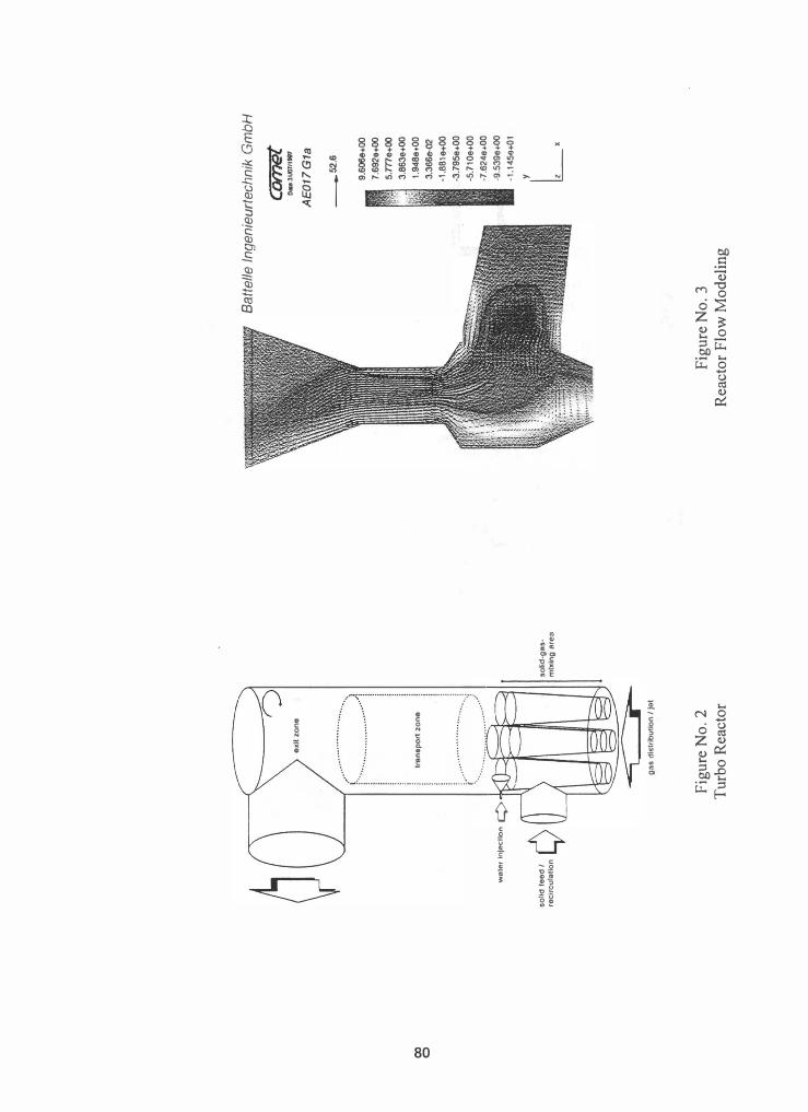
The flue gas desulfurization system is arranged directly behind the boiler. The flue gas flows into the turbo-reactor via a venturi nozzle or a gasdistributing bottom. The temperature is decreased to the optimum operating value by the injection of water in order to increase the reactivity. See Figure No.2 for details.
In the turbo-reactor the flue gas gets in turbulent contact with the absorbent so that pollutants like S02, S03, HCI and HF are removed in a high extent. A minor reaction is the absorption of low amounts of carbon dioxide as well. A considerable part of the calcium sulfite having formed this way is oxidized further into calcium sulfate.
Due to the high velocities in the turbo-reactor the solids are discharged at the head of the reactor and separated in the directly adjoining baghouse. The filters are specially designed electrostatic precipitators or fabric filters which both are provided with an integrated upstream mechanical
• •
pre-separatIOn umt. Flue gas that has had the particulates removed
to the prescribed limit values in the fabric filter is led into the stack by means of the ID-fan. In coal fired power plants, reheating is not necessary as the clean gas temperature is approx. 175 to 212°F (80 to 100°C), and in any case it is at least 20°C above the water dew point. In waste-to-energy plants the baghouse flue gas temperature has to be higher in the range of 275°F (135°C) due to the higher chloride content of the ash.
In order to allow the operation of the reactor even at low boiler loads, i.e. at raw gas flows of <50%, part of the clean gas has to be recirculated.

A major part of the solids eliminated by the baghouse is fed back from an intermediate tank into the turboreactor by means of fluidizing conveyors. Therefore residence times of almost any required duration can be achieved and, what is characteristic of this process, very high degrees of utilization of the absorbent. In addition to the savings in the consumption of fresh absorbent the production of residues also is minimized.
Only a small fraction of the residues collected by the filter is pneumatically conveyed into the residue silo. The final product can be stabilized but also can be used without any further treatment for landfilling or as make-up material for the building material or cement industries.
For smaller plants the fresh absorbent is commercially available hydrated lime Ca (OHk For larger plants operating costs can be reduced by slaking quicklime (CaO) on site to produce a slurry or milk of lime.
The input of absorbent from the silo into the turboreactor is made by means of a controlled discharging device and a pneumatic conveying unit.
An economically very interesting alternative is the injection of comparably cheap limestone powder into the boiler, thus pre-de sulfurizing the flue gases. Then the resulting product of fly ashes and product (CaO/CaS04) is used further in the Turbosorp® process without pre-particulate removal. The injection of limestone into the combustion chamber is known as "Furnance Limestone Injection" process on which comprehensive know-how is available.
The water that is required is pumped into a header ring by means of a high-pressure (lIP) pump and injected into the turboreactor via a HP backflow nozzle. The effects of this process step consist in the cooling of the flue gas, thus increasing the relative humidity, and in moistening the great amounts of solids in the reactor, thus increasing the reactivity.
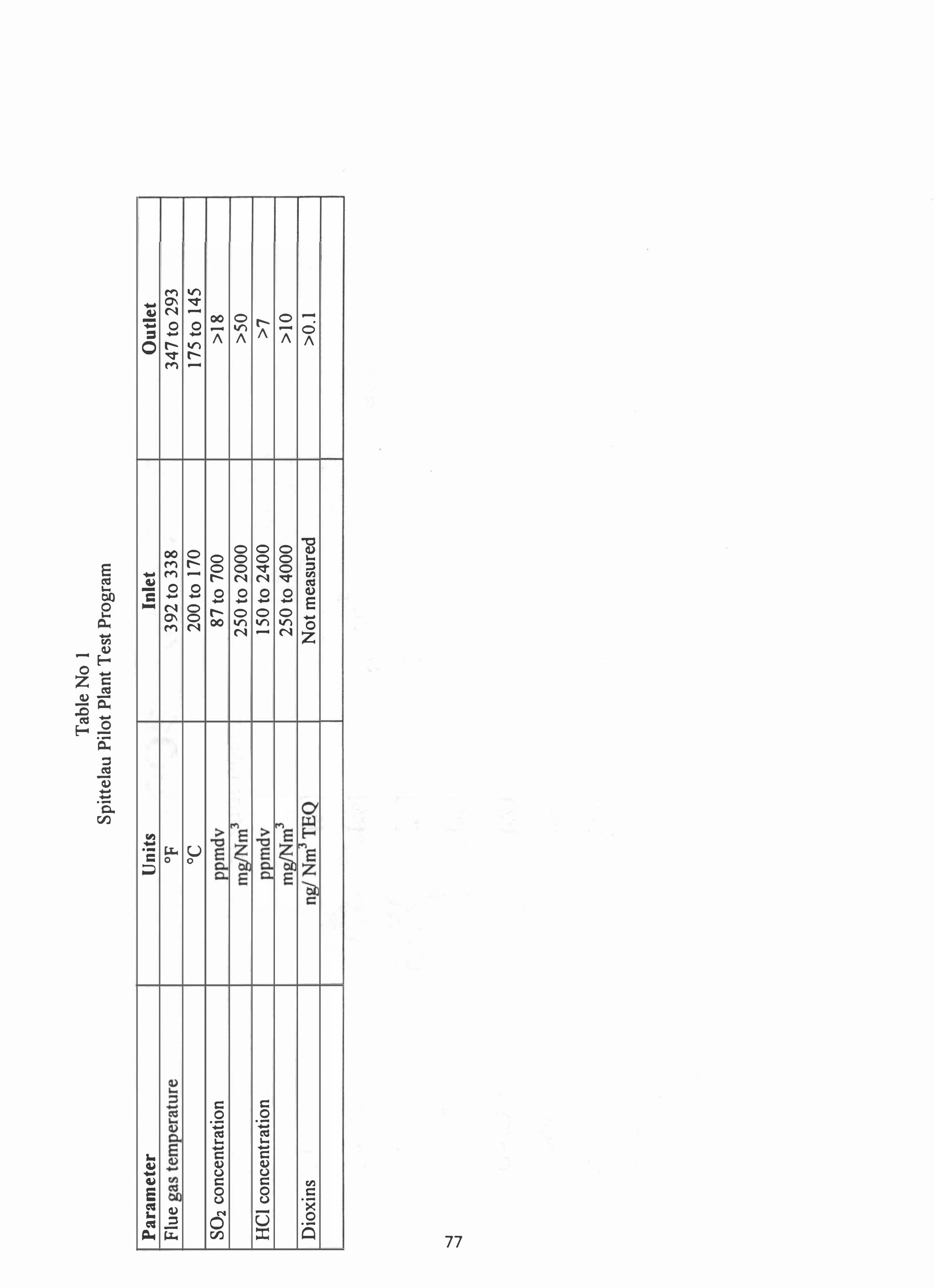
Reactor Modeling
One of the key parameters in the development of the fluidizing bed reactor is the modeling of the flue gas flow. The inflow to the turboreactor is
75
examined and optimized by the means of a threedimensional model of the flue gas flow. With this technique a stable operation can be achieved for a very wide range of flows.
The turboreactor is subdivided into areas and are modeled in several phases. Together with the findings from the laboratory experiments the reactor can be optimized. Particularly critical areas such as the reactor head or the water injection zones are examined in detail. See Figure No. 3 for an example of the a typical modeling profile.
Main Advantages of Turbosorp@ Process
• Low investment cost
• High removal efficiencies S02 < 95% HCI > 98% HF > 99% S03 > 99% Partic1ulates> 99 %
• High availability
• Short implementation times
• Low space requirements
• Final product marketable or suited for landfills
• Process without the production of waste water
• Optimum utilization of the absorbent due to repeated circulation of the solids
•
•
Low operating cost due to savings in the absorbent
Low maintenance cost due to the absence of moving parts in the reactor
• Other sorbents such as activated carbon or sodium tetrasulfide can be added to the reactor to remove mercury and or dioxins in a single application.
• When hydrated lime is employed as the sorbent it can be injected dry.
• Both quicklime and hydrated lime can be used as the primary sorbent.
Waste-to-Energy Applications
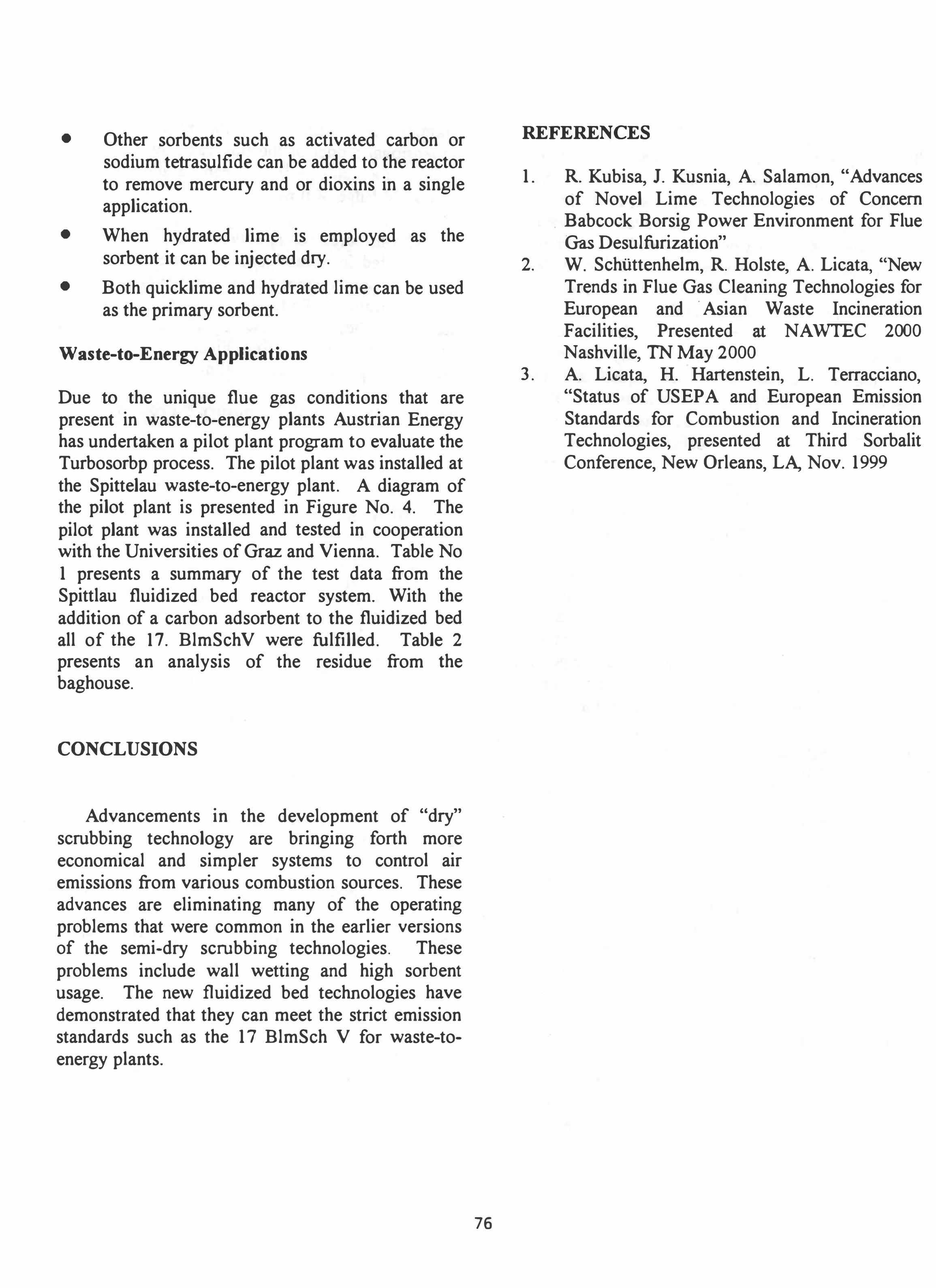
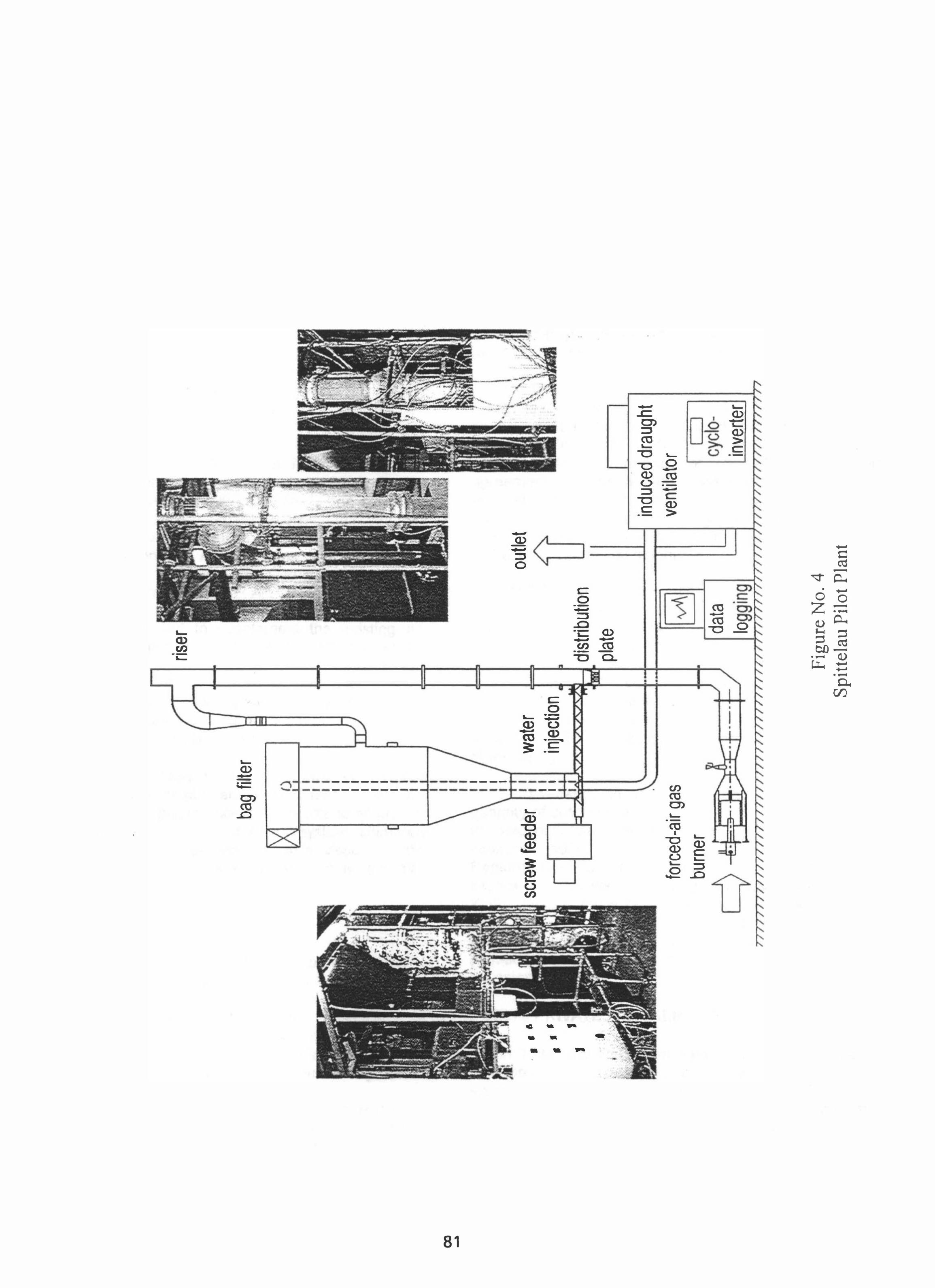
Due to the unique flue gas conditions that are present in waste-to-energy plants Austrian Energy has undertaken a pilot plant program to evaluate the Turbosorbp process. The pilot plant was installed at the Spittelau waste-to-energy plant. A diagram of the pilot plant is presented in Figure No. 4. The pilot plant was installed and tested in cooperation with the Universities ofGraz and Vienna. Table No 1 presents a summary of the test data from the Spittlau fluidized bed reactor system. With the addition of a carbon adsorbent to the fluidized bed all of the 17. BlmSch V were fulfilled. Table 2 presents an analysis of the residue from the baghouse.
CONCLUSIONS
Advancements in the development of "dry" scrubbing technology are bringing forth more economical and simpler systems to control air emissions from various combustion sources. These advances are eliminating many of the operating problems that were common in the earlier versions of the semi-dry scrubbing technologies. These problems include wall wetting and high sorbent usage. The new fluidized bed technologies have demonstrated that they can meet the strict emission standards such as the 17 BlmSch V for waste-toenergy plants.
76
REFERENCES
1. R. Kubisa, 1. Kusnia, A. Salamon, "Advances of Novel Lime Technologies of Concern
. Babcock Borsig Power Environment for Flue Gas Desulfurization"
2. W. Schuttenhelm, R. Holste, A. Licata, "New Trends in Flue Gas Cleaning Technologies for European and . Asian Waste Incineration Facilities, Presented at NA WTEC 2000 Nashville, TN May 2000
3. A. Licata, H. Hartenstein, L. Terracciano, "Status of USEP A and European Emission Standards for Combustion and Incineration Technologies, presented at Third Sorbalit Conference, New Orleans, LA, Nov. 1999
Tabl
e No
1 Sp
ittel
au P
ilot P
lant
Tes
t Pro
gram
Pa
ram
eter
U
nit
s In
let
Ou
tlet
Fl
ue g
as te
mpe
ratu
re
o f 3
92
to 3
38
3
47
to 2
93
°C
200
to 1
70
17
5 to
14
5
S02
conc
entra
tion
)pm
dv
87
to 7
00
>
18
mg/Nm
" 2
50
to 2
00
0
>5
0
HC
I con
cent
ratio
n vv
mdv
15
0 to
24
00
>
7
mg/N
mJ
25
0 to
40
00
>
10
Dio
xins
ngl
Nm
"TE
Q
Not
mea
sure
d >
0.1
-...J
-...J

Ta
ble
2 An
aly
sis
of
Ba
gh
ou
se R
esid
ue
Co
mp
one
nt
Ran
ge
Exp
ecte
d -
Ca
S0
3*0,
5H
20
[%]
1 -
10
3
Ca
S0
4*xH
20
[0/ 0] 2
-10
4
Ca
C0
3 [%
] 8
-2
5
6
Ca
(OH
)2
[0/0]
5 -
20
7,5
-..J
Ca
Cb
[0/0
] 5
-30
10
00
Ca
F2
[0/0]
0.5
-3
1
Fly
ash
* [0/0
] 2
0-8
0 62
.5
Mo
istu
re
[0/0]
0.3
-2
< 1
* w
ith n
o s
epa
ratio
n o
f fly
ash
aft
er
boile
r

'ooJ
1.0
"
. -"'
._
'-'�
'--O:
_. -
•
Pre
P
reci
pit
ato
r
8ag
ho
use
F
an
�
�
""
"
.
Ca(
OH
)? -•
.
Illi S
tack
S
ilo
Tu
rbo
-A
ctiv
e C
arb
on
-R
eact
or
Ril
n
.. , .•.
• "1
Wat
er
Inje
ctio
n
Flu
e g
as
fro
m
com
bu
stio
n .
"'
So
rbe
nt-R
eci
rcu
lati
on
Sy
ste
m
Pro
du
ct S
ilo
Figu
re N
o.1
00
o
wei
er In
ject
ion
¢
so
lidf
eO
dl
A
re
clr
cu
laU
on
y
?J
ex
it z
on
e
tmoa
part
zo
ne
l····
'"
. ...... .1 ....
�.
--=c:::r--
ga
s d
istr
ibu
tio
n I
/et
Figu
re N
o.2
T
urbo
Rea
ctor
so
lid-g
as
m
ixin
g a
rea
Batte
lle In
geni
eurt
echn
ik G
mbH
Figu
re N
o.3
R
eact
or F
low
Mod
elin
g
camel
O .. 3IJ01l1
t8'1
AE
017
G1a
_52
.6
9.6
06&+
00
7.6
92
0.0
0
5.m
e+
00
3.8
63
e+
OO
1.9
48
0.
00
3.3
66
tHl2
-1
.88
10
+0
0
-3.7
95
e.
00
-5.7
10
e+
00
-7.6
24
e+
OO
-9.5
3g
e+o
o
-1.1
45
6+
01
Lx
00
.....
•
• •
•
•••
, '
:.
bag
filte
r
I I
I I
I I
I I
I I
I I
I
scre
w fe
eder
I: I
I I I I T
I I
forc
ed-a
ir ga
s bu
rner
wate
r inj
ectio
n
• riser
distri
butio
n pl
ate da
ta
10
outle
t
Figu
re N
o.4
Sp
itte
lau
Pilo
t Pla
nt
indu
ced
drau
ght
vent
ilato
r I
I cy
clo-
inve
rter