drum instruction programming - automationdirectdrum instruction programming 6--2 drum instruction...
TRANSCRIPT

16Drum InstructionProgramming
In This Chapter. . . .— Introduction— Step Transitions— Overview of Drum Operation— Drum Control Techniques— Drum Instructions

DrumInstruction
Program
ming
6--2Drum Instruction Programming
DL350 User Manual, 2nd Edition
Introduction
The four drum instructions available in the DL350 CPU electronically simulate anelectro-mechanical drum sequencer. The instructions offer slight variations on thebasic principle.Drum instructions are best suited for repetitive processes consisting of a finitenumber of steps. They can do the work of many rungs of ladder logic with simplicity.Therefore, drums can save a programming and debugging time.We introduce some terminology associated with drum instructions by describing theoriginal electro-mechanical drum pictured below. The mechanical drum generallyhas pegs on its curved surface. The pegs are populated in a particular pattern,representing a set of desired actions formachine control. Amotor or solenoid rotatesthedrumaprecise amount at specific times.During rotation, stationarywipers sensethe presence of pegs (present = on, absent = off). This interaction makes or breakselectrical contact with the wipers, creating electrical outputs from the drum. Theoutputs are wired to devices on a machine for On/Off control.Drums usually have a finite number of positions within one rotation, called steps.Each step represents some process step. At powerup, the drum resets to aparticular step. The drum rotates from one step to the next based on a timer, or onsome external event. During special conditions, a machine operator can manuallyincrement the drum step using a jog control on the drum’s drive mechanism. Thecontact closure of each wiper generates a unique on/off pattern called a sequence,designed for controlling a specific machine. Because the drum is circular, itautomatically repeats the sequence once per rotation. Applications vary greatly, anda particular drum may rotate once per second, or as slowly as once per week.
Drum
Outputs
Wipers
Pegs
Electronic drums provide the benefits of mechanical drums andmore. For example,they have a preset feature that is impossible for mechanical drums: The presetfunction lets youmove from the present step directly to any other step on command!
Purpose
Drum Terminology
Drum
InstructionProgram
ming
6--3Drum Instruction Programming
DL350 User Manual, 2nd Edition
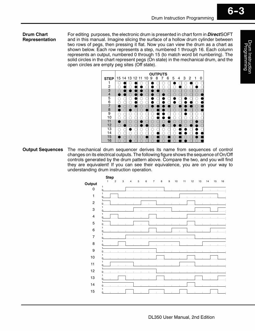
For editing purposes, the electronic drum is presented in chart form inDirectSOFTand in this manual. Imagine slicing the surface of a hollow drum cylinder betweentwo rows of pegs, then pressing it flat. Now you can view the drum as a chart asshown below. Each row represents a step, numbered 1 through 16. Each columnrepresents an output, numbered 0 through 15 (to match word bit numbering). Thesolid circles in the chart represent pegs (On state) in the mechanical drum, and theopen circles are empty peg sites (Off state).
1STEP
2345678910111213141516
f F f F f f F f f f F f f F f ff F f F F f F f f f f F f f F ff F F F F f F F f f f f f f f fF F f F F f F f F f f f f f f F
F f f F f f F F F F f F F F f FF f F f f F f F F f f f F f f F
f f f F f f F f F f F f F f f Ff f f F f f F f F f F f F F f F
f f f f f f f F F f f f F f f ff f f f f f f F F F f f f f f fF f f f F f f f f F f f f f F ff F f f F F f f F f F F f F F ff f F f f f f f f f f F F f F ff f f f f f f F f f f F F f F FF f f f f F f F f F f F f f F Ff f F f f f f F f F f F F f f F
123456789101112131415 0OUTPUTS
The mechanical drum sequencer derives its name from sequences of controlchanges on its electrical outputs. The following figure shows the sequence ofOn/Offcontrols generated by the drum pattern above. Compare the two, and you will findthey are equivalent! If you can see their equivalence, you are on your way tounderstanding drum instruction operation.
0 01
1 01
2 01
3 01
4 01
5 01
6 01
7 01
8 01
9 01
10 01
11 01
12 01
13 01
14 01
15 01
Output1 2 3 4 5 6 7 8 9 10 11 12 13 14 15 16Step
Drum ChartRepresentation
Output Sequences
DrumInstruction
Program
ming
6--4Drum Instruction Programming
DL350 User Manual, 2nd Edition
Step Transitions
There are four types of Drum instructions in the DL350 CPU:S Timed Drum with Discrete Outputs (DRUM)S Time and Event Drum with Discrete Outputs (EDRUM)S Masked Event Drum with Discrete Outputs (MDRUMD)S Masked Event Drum with Word Output (MDRUMW)
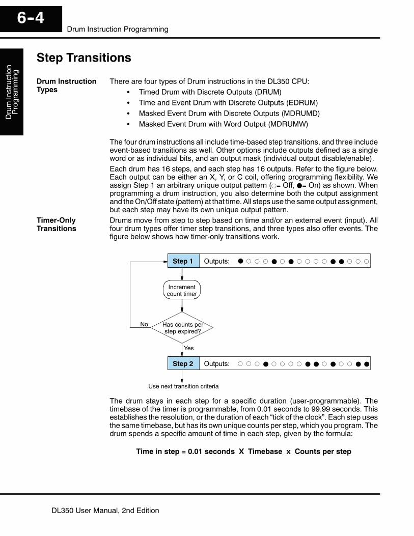
The four drum instructions all include time-based step transitions, and three includeevent-based transitions as well. Other options include outputs defined as a singleword or as individual bits, and an output mask (individual output disable/enable).Each drum has 16 steps, and each step has 16 outputs. Refer to the figure below.Each output can be either an X, Y, or C coil, offering programming flexibility. Weassign Step 1 an arbitrary unique output pattern (f= Off, F= On) as shown. Whenprogramming a drum instruction, you also determine both the output assignmentand theOn/Off state (pattern) at that time.All steps use the sameoutput assignment,but each step may have its own unique output pattern.Drums move from step to step based on time and/or an external event (input). Allfour drum types offer timer step transitions, and three types also offer events. Thefigure below shows how timer-only transitions work.
F f f f F f F f f f f F F f f fStep 1 Outputs:
f f f F f f f f F F f F f f F FStep 2 Outputs:
Has counts perstep expired?
No
Yes
Incrementcount timer
Use next transition criteria
The drum stays in each step for a specific duration (user-programmable). Thetimebase of the timer is programmable, from 0.01 seconds to 99.99 seconds. Thisestablishes the resolution, or the duration of each “tick of the clock”. Each step usesthe same timebase, but has its own unique counts per step, which you program. Thedrum spends a specific amount of time in each step, given by the formula:
Time in step = 0.01 seconds X Timebase x Counts per step
Drum InstructionTypes
Timer-OnlyTransitions
Drum
InstructionProgram
ming
6--5Drum Instruction Programming
DL350 User Manual, 2nd Edition
For example, if you programa5second timebase and12 counts for Step1, the drumwill spend 60 seconds in Step 1. The maximum time for any step is given by theformula:
Max Time per step = 0.01 seconds X 9999 X 9999= 999,800 seconds = 277.7 hours = 11.6 days
NOTE: When first choosing the timebase resolution, a good rule is to make itapproximately 1/10 the duration of the shortest step in your drum. You will be able tooptimize the duration of that step in 10% increments. Other steps with longerdurations allow optimizing by even smaller increments (percentage-wise). Also,note the drum instruction executes once per CPU scan. Therefore, it is pointless tospecify a drum timebase faster than the CPU scan time.
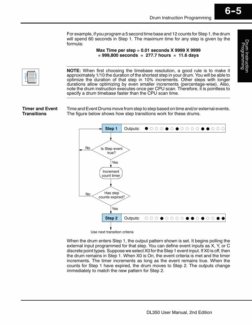
TimeandEventDrumsmove fromstep to step basedon timeand/or external events.The figure below shows how step transitions work for these drums.
Is Step eventtrue?
F f f f F f F f f f f F F f f fStep 1 Outputs:
f f f F f f f f F F f F f f F FStep 2 Outputs:
No
Yes
Incrementcount timer
Has stepcounts expired?
No
Yes
Use next transition criteria
When the drum enters Step 1, the output pattern shown is set. It begins polling theexternal input programmed for that step. You can define event inputs as X, Y, or Cdiscrete point types. Supposeweselect X0 for theStep1event input. If X0 is off, thenthe drum remains in Step 1. When X0 is On, the event criteria is met and the timerincrements. The timer increments as long as the event remains true. When thecounts for Step 1 have expired, the drum moves to Step 2. The outputs changeimmediately to match the new pattern for Step 2.
Timer and EventTransitions

DrumInstruction
Program
ming
6--6Drum Instruction Programming
DL350 User Manual, 2nd Edition
Time and Event drums do not have to possess both the event and the timer criteriaprogrammed for each step. You have the option of programming one of the two, andevenmixing transition types amongall the steps of the drum. For example, youmightwant Step 1 to transition on an event, Step 2 to transition on time only, and Step 3 totransition on both time and an event. Furthermore, you may elect to use only part ofthe 16 steps, and only part of the 16 outputs.
Is Step eventtrue?
F f f f F f F f f f f F F f f fStep 1 Outputs:
f f f F f f f f F F f F f f F FStep 2 Outputs:
No
Yes
Use next transition criteria
Each drum instruction uses the resources of four counters in the CPU.Whenprogramming the drum instruction, you select the first counter number. The drumalso uses the next three counters automatically. The counter bit associated with thefirst counter turns on when the drum has completed its cycle, going off when thedrum is reset. These counter values and counter bit precisely indicate the progressof the drum instruction, and can be monitored by your ladder program.
Suppose you program a timer drum tohave 8 steps, and we select CT10 for thecounter number (remember, counternumbering is in octal). Counter usage isshown to the right. The right column holdstypical values, interpreted below.
CT10 Counts in step V1010 1528
CT11 Timer Value V1011 0200
CT12 Preset Step V1012 0001
CT13 Current Step V1013 0004
Counter Assignments
CT10shows youare at the 1528th count in the current step,which is step4 (shown inCT13). If we have programmed step 4 to have 3000 counts, the step is over halfcompleted. CT11 is the count timer, shown in units of 0.01 seconds. So, eachleast-significant-digit change represents 0.01 seconds. The value of 200means youhave been in the current count (1528) for 2 seconds (0.01 x 100). Finally, CT12holdsthe preset step value which was programmed into the drum instruction. When thedrum’s Reset input is active, it presets to step 1 in this case. The value of CT12 doesnot changewithout a programedit. Counter bit CT10 turns onwhen the drumcycle iscomplete, and turns off when the drum is reset.
Event-OnlyTransitions
CounterAssignments
Drum
InstructionProgram
ming
6--7Drum Instruction Programming
DL350 User Manual, 2nd Edition
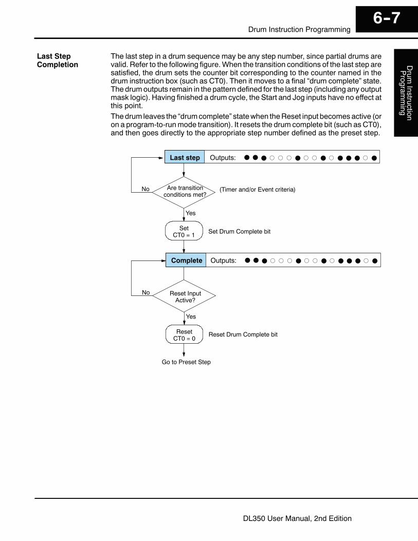
The last step in a drum sequence may be any step number, since partial drums arevalid. Refer to the following figure.When the transition conditions of the last step aresatisfied, the drum sets the counter bit corresponding to the counter named in thedrum instruction box (such as CT0). Then it moves to a final “drum complete” state.The drumoutputs remain in the pattern defined for the last step (including any outputmask logic). Having finished a drum cycle, the Start and Jog inputs have no effect atthis point.Thedrum leaves the “drumcomplete” statewhen theReset input becomesactive (oron a program-to-runmode transition). It resets the drum complete bit (such as CT0),and then goes directly to the appropriate step number defined as the preset step.
Are transitionconditions met?
F F F f f f F f f F f F F F f FLast step Outputs:
F F F f f f F f f F f F F F f FComplete Outputs:
No
Yes
Go to Preset Step
SetCT0 = 1
Reset InputActive?
No
Yes
ResetCT0 = 0
(Timer and/or Event criteria)
Set Drum Complete bit
Reset Drum Complete bit
Last StepCompletion

DrumInstruction
Program
ming
6--8Drum Instruction Programming
DL350 User Manual, 2nd Edition
Overview of Drum Operation
The drum instruction utilizes various inputs and outputs in addition to the drumpattern itself. Refer to the figure below.
Reset
Preset Step
Jog *
Timebase
Counts/Step
f f F f f f
f f f f f ff f f f F f
F F f F F ff F F f F f
f F F f F Ff F f f F F
f F F f f F
Outputs OutputMask *
StepControl
StepPointer
Drum
DRUM INSTRUCTIONBlock Diagram
Inputs Outputs
Final DrumOutputs
CT0 Counts in step V1000 xxxx
CT1 Timer Value V1001 xxxx
CT2 Preset Step V1002 xxxx
CT3 Current Step V1003 xxxx
Counter #
Output Mask *
Pattern
Counter Assignments
* Asterisked inputsare applicable onlyto particular druminstructions.
Events *
RealtimeInputs
(from ladder)
ProgrammingSelections
Start
The drum instruction accepts several inputs for step control, the main control of thedrum. The inputs and their functions are:
S Start -- The Start input is effective only when Reset is off. When Start ison, the drum timer runs if it is in a timed transition, and the drum looksfor the input event during event transitions. When Start is off, the drumfreezes in its current state (Reset must remain off), and the drumoutputs maintain their current on/off pattern.
S Jog -- The jog input is only effective when Reset is off (Start may beeither on or off). The jog input increments the drum to the next step oneach off-to-on transition. Note that only the basic timer drum does nothave a jog input.
S Reset -- The Reset input has priority over the Start input. When Reset ison, the drum moves to its preset step. When Reset is off, then the Startinput operates normally.
S Preset Step -- A step number from 1 to 16 that you define (typically isstep 1). The drum moves to this step whenever Reset is on, andwhenever the CPU first enters run mode.
Drum InstructionBlock Diagram
Drum
InstructionProgram
ming
6--9Drum Instruction Programming
DL350 User Manual, 2nd Edition
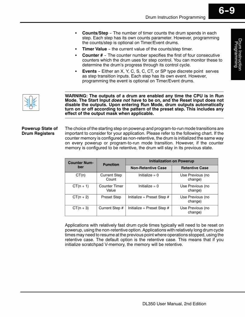
S Counts/Step -- The number of timer counts the drum spends in eachstep. Each step has its own counts parameter. However, programmingthe counts/step is optional on Timer/Event drums.
S Timer Value -- the current value of the counts/step timer.S Counter # -- The counter number specifies the first of four consecutive
counters which the drum uses for step control. You can monitor these todetermine the drum’s progress through its control cycle.
S Events -- Either an X, Y, C, S, C, CT, or SP type discrete point servesas step transition inputs. Each step has its own event. However,programming the event is optional on Timer/Event drums.
WARNING: The outputs of a drum are enabled any time the CPU is in RunMode. The Start Input does not have to be on, and the Reset input does notdisable the outputs. Upon entering Run Mode, drum outputs automaticallyturn on or off according to the pattern of the preset step. This includes anyeffect of the output mask when applicable.
The choice of the starting step on powerup and program-to-runmode transitions areimportant to consider for your application. Please refer to the following chart. If thecounter memory is configured as non-retentive, the drum is initialized the samewayon every powerup or program-to-run mode transition. However, if the countermemory is configured to be retentive, the drum will stay in its previous state.
Counter Num- FunctionInitialization on PowerupCounter Num
berFunction
Non-Retentive Case Retentive Case
CT(n) Current StepCount
Initialize = 0 Use Previous (nochange)
CT(n + 1) Counter TimerValue
Initialize = 0 Use Previous (nochange)
CT(n + 2) Preset Step Initialize = Preset Step # Use Previous (nochange)
CT(n + 3) Current Step # Initialize = Preset Step # Use Previous (nochange)
Applications with relatively fast drum cycle times typically will need to be reset onpowerup, using the non-retentive option. Applicationswith relatively long drumcycletimesmayneed to resumeat the previous point where operations stopped, using theretentive case. The default option is the retentive case. This means that if youinitialize scratchpad V-memory, the memory will be retentive.
Powerup State ofDrum Registers

DrumInstruction
Program
ming
6--10Drum Instruction Programming
DL350 User Manual, 2nd Edition
Drum Control Techniques
Now we are ready to put together theconcepts on the previous pages anddemonstrate general control of the druminstruction box. The drawing to the rightshows a simplified generic druminstruction. Inputs from ladder logiccontrol the Start, Jog, and Reset Inputs.The first counter bit of the drum (CT0, forexample) indicates the drum cycle isdone.
f f F f f f
f f f f f ff f f f F f
F F f F F ff F F f F f
f F F f F Ff F f f F F
f F F f f F
Outputs
Steps
SetupInfo.
X0
X1
Mask
Start
Jog
X2 Reset
The timing diagram below shows an arbitrary timer drum input sequence and howthe drum responds. As the CPU enters run mode it initializes the step number to thepreset step number (typically is Step 1). When the Start input goes high the drumbegins running, looking for an event and/or running the count timer (depending onthe drum type and setup).After the drum enters Step 2, Reset turns On while Start is still On. Since Reset haspriority over Start, the drum goes to the preset step (Step 1). Note the drum is held inthe preset step duringReset, and that stepdoes not run (respond to events or run thetimer) until Reset turns off.After the drum has entered step 3, the Start input goes off momentarily, halting thedrum’s timer until Start turns on again.
Start 01
Jog 01
Step #
DrumComplete (CT0) 0
1
Inputs
1 1 2 1 1 2 3 3 4 ... 15 16 16 16 1 1
Drum Status
Startdrum
Resetdrum
Holddrum
Resumedrum
DrumComplete
Resetdrum
01
Outputs (x 16)
Reset 01
When the drum completes the last step (Step 16 in this example), the DrumComplete bit (CT0) turns on, and the step number remains at 16. When the Resetinput turns on, it turns off the DrumComplete bit (CT0), and forces the drum to enterthe preset step.
NOTE: The timing diagram shows all steps using equal time durations. Step timescan vary greatly, depending on the counts/step programmed.
DrumControl Inputs

Drum
InstructionProgram
ming
6--11Drum Instruction Programming
DL350 User Manual, 2nd Edition
In the figure below, we focus on how the Jog input works on event drums. To the leftof the diagram, note the off-to-on transitions of the Jog input increments the step.Startmay beeither on or off (however, Resetmust be off). Two jogs takes the drum tostep three. Next, the Start input turns on, and the drum begins running normally.During step 6 another Jog input signal occurs. This increments the drum to step 7,setting the timer to 0. The drum begins running immediately in step 7, because Startis already on. The drum advances to step 8 normally.As the drumenters step 14, theStart input turns off. Twomore Jog signalsmoves thedrum to step 16. However, note that a third Jog signal is required to move the drumthrough step 16 to “drumcomplete”. Finally, aReset input signal arriveswhich forcesthe drum into the preset step and turns off the drum complete bit.
Start 01
Reset 01
Step #
DrumComplete (CT0) 0
1
Inputs
1 2 3 3 3 4 5 6,7 8 ... 14 15 16 16 16 1
Drum Status
Jogdrum
Resetdrum
Jogdrum
DrumComplete
01
Outputs (x 16)
Jog 01
Jogdrum
Applications often require drums thatautomatically start over once theycomplete a cycle. This is easilyaccomplished, using the drum completebit. In the figure to the right, the druminstruction setup is for CT0, sowe logicallyOR the drum complete bit (CT0) with theReset input. When the last step is done,the drum turns on CT0 which resets itselfto the preset step, also resetting CT0.Contact X1 still works as a manual reset.
f f F f f f
f f f f f ff f f f F f
F F f F F ff F F f F f
f F F f F Ff F f f F F
f F F f f F
Outputs
Steps
SetupInfo.
X0
X1Mask
Start
Reset
CT0
The outputs of a drum are enabled any time the CPU is in run mode. Onprogram-to-run mode transitions, the drum goes to the preset step, and the outputsenergize according to the pattern of that step. If your application requires all outputsto be off at powerup, there are two approaches:
S Make the preset step in the drum a “reset step”, with all outputs off.S Or, use a drum with an output mask. Initialize the mask to “0000” on the
first scan using contact SP0, and LD K000 and OUT Vxxx instructions,where Vxxxx is the location of the mask register.
Self-ResettingDrum
Initializing DrumOutputs

DrumInstruction
Program
ming
6--12Drum Instruction Programming
DL350 User Manual, 2nd Edition
Drum Instructions
The DL350 drum instructions may be programmed using DirectSOFT or for theEDRUM instruction only you can use a handheld programmer (firmware versionv1.8 or later. This section covers entry usingDirectSOFT for all instructions plus thehandheld mnemonics for the EDRUM instruction.The Timed Drum with Discrete Outputs is the most basic of the DL350’s druminstructions. It operates according to the principles covered on the previous pages.Below is the instruction in chart form as displayed by DirectSOFT.
Start
Reset
Discrete Output AssignmentCounter Number
ControlInputs
Step Number
Counts per Step
Output Patternf= Off, F= On
Step PresetTimebase
The Timed Drum features 16 steps and 16 outputs. Step transitions occur only on atimed basis, specified in counts per step. Unused steps must be programmed with“counts per step” = 0 (this is the default entry). The discrete output points may beindividually assigned as X, Y, or C types, or may be left unused. The output patternmay be edited graphically with DirectSOFT.Whenever the Start input is energized, the drum’s timer is enabled. It stopswhen thelast step is complete, or when the Reset input is energized. The drum enters thepreset step chosen upon a CPU program-to-run mode transition, and whenever theReset input is energized.Drum Parameters Field Data Types Ranges
Counter Number aaa -- 0 -- 177
Preset Step bb K 1 -- 16
Timer base cccc K 0 -- 99.99 seconds
Counts per step dddd K 0 -- 9999
Discrete Outputs Fffff X, Y, C see page 3--29
Timed Drum withDiscrete Outputs(DRUM)

Drum
InstructionProgram
ming
6--13Drum Instruction Programming
DL350 User Manual, 2nd Edition
Drum instructions use four counters in the CPU. The ladder program can read thecounter values for the drum’s status. The ladder program may write a new presetstep number to CT(n+2) at any time. However, the other counters are for monitoringpurposes only.
Counter Number Ranges of (n) Function Counter Bit Function
CT(n) 0 -- 124 Counts in step CTn = Drum Complete
CT( n+1) 1 -- 125 Timer value CT(n+1) = (not used)
CT( n+2) 2 --126 Preset Step CT(n+2) = (not used)
CT( n+3) 3 --127 Current Step CT(n+1) = (not used)
The following ladder program shows the DRUM instruction in a typical ladderprogram, as shown by DirectSOFT. Steps 1 through 10 are used, and twelve of thesixteen output points are used. The preset step is step 1. The timebase runs at 100mSper count. Therefore, the duration of step 1 is (25 x 0.1) = 2.5 seconds. In the lastrung, the Drum Complete bit (CT0) turns on output Y0 upon completion of the laststep (step 10). A drum reset also resets CT0.
DrumInstruction
Program
ming
6--14Drum Instruction Programming
DL350 User Manual, 2nd Edition
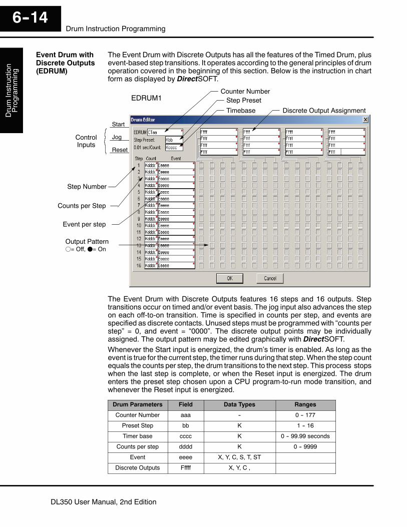
The Event Drum with Discrete Outputs has all the features of the Timed Drum, plusevent-based step transitions. It operates according to the general principles of drumoperation covered in the beginning of this section. Below is the instruction in chartform as displayed by DirectSOFT.
Discrete Output Assignment
Counter NumberStep Preset
ControlInputs
Step Number
Counts per Step
Output Patternf= Off, F= On
Start
Reset
Jog
Event per step
EDRUM1
Timebase
The Event Drum with Discrete Outputs features 16 steps and 16 outputs. Steptransitions occur on timed and/or event basis. The jog input also advances the stepon each off-to-on transition. Time is specified in counts per step, and events arespecified as discrete contacts. Unused steps must be programmedwith “counts perstep” = 0, and event = “0000”. The discrete output points may be individuallyassigned. The output pattern may be edited graphically with DirectSOFT.Whenever the Start input is energized, the drum’s timer is enabled. As long as theevent is true for the current step, the timer runs during that step.When the step countequals the counts per step, the drum transitions to the next step. This process stopswhen the last step is complete, or when the Reset input is energized. The drumenters the preset step chosen upon a CPU program-to-run mode transition, andwhenever the Reset input is energized.
Drum Parameters Field Data Types Ranges
Counter Number aaa -- 0 -- 177
Preset Step bb K 1 -- 16
Timer base cccc K 0 -- 99.99 seconds
Counts per step dddd K 0 -- 9999
Event eeee X, Y, C, S, T, ST
Discrete Outputs Fffff X, Y, C ,
Event Drum withDiscrete Outputs(EDRUM)

Drum
InstructionProgram
ming
6--15Drum Instruction Programming
DL350 User Manual, 2nd Edition
Drum instructions use four counters in the CPU. The ladder program can read thecounter values for the drum’s status. The ladder program may write a new presetstep number to CT(n+2) at any time. However, the other counters are for monitoringpurposes only.
Counter Number Ranges of (n) Function Counter Bit Function
CT(n) 0 -- 124 Counts in step CTn = Drum Complete
CT( n+1) 1 -- 125 Timer value CT(n+1) = (not used)
CT( n+2) 2 --126 Preset Step CT(n+2) = (not used)
CT( n+3) 3 --127 Current Step CT(n+1) = (not used)
The following ladder program shows the EDRUM instruction in a typical ladderprogram, as shown by DirectSOFT. Steps 1 through 11 are used, and all sixteenoutput points are used. The preset step is step 1. The timebase runs at 100 mS percount. Therefore, the duration of step 1 is (5 x 0.1) = 0.5 seconds. Note that step 1 istime-based only (event = “K0000”). And, the output pattern for step 1 programs alloutputs off, which is a typically desirable powerup condition. In the last rung, theDrum Complete bit (CT4) turns on output Y0 upon completion of the last step (step10). A drum reset also resets CT4.

DrumInstruction
Program
ming
6--16Drum Instruction Programming
DL350 User Manual, 2nd Edition
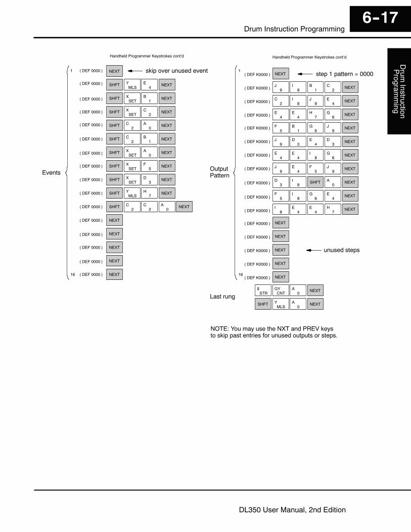
The handheld programmer can also enter or edit drum instructions. The diagrambelow lists the keystrokes for entering the drum example on the previous page.
NOTE: Drum editing requires Handheld Programmer firmware version 1.8 or later.
Handheld Programmer Keystrokes
Start
( DEF K0001)
Reset
Drum Inst.
( DEF 0000 )
( DEF 0000 )
( DEF 0000 )
( DEF K0000 )
Preset Step
Time Base
( DEF 0000 )
( DEF 0000 )
( DEF 0000 )
( DEF 0000 )
( DEF 0000 )
( DEF 0000 )
( DEF 0000 )
( DEF 0000 )
( DEF 0000 )
( DEF 0000 )
( DEF 0000 )
( DEF 0000 )
( DEF 0000 )
Outputs
( DEF K0000 )
( DEF K0000 )
( DEF K0000 )
( DEF K0000 )
( DEF K0000 )
( DEF K0000 )
( DEF K0000 )
( DEF K0000 )
( DEF K0000 )
( DEF K0000 )
( DEF K0000 )
( DEF K0000 )
( DEF K0000 )
( DEF K0000 )
( DEF K0000 )
( DEF K0000 )
Counts/Step
skip overunused steps
NOTE: You may use the NXT and PREV keysto skip past entries for unused outputs or steps.
(Continued on next page)
Jog
STR$
0A
STR$
1B
STR$
2C
SHFT4
E3
DORNR
ISGU
ORSTM
0A ENT
4E
6G
NEXT
NEXT
ENT
ENT
ENT
SHFT2
C7
H NEXT
SHFT2
C0
A NEXT1
B
SHFTMLSY
1B NEXT
SHFTMLSY NEXT
4E
SHFTMLSY
5F NEXT
SHFTMLSY
6G NEXT
SHFT2
C4
E NEXT
SHFT2
C2
C NEXT
SHFTMLSY NEXT
0A
SHFTMLSY NEXT
2C
SHFT2
C1
B4
E NEXT
SHFT2
C NEXT3
D0
A
SHFTMLSY NEXT
6G
SHFTMLSY NEXT
7H
SHFT2
C3
D4
E NEXT
SHFTMLSY
1B NEXT
1
16
1
16
5F NEXT
2C
0A NEXT
1B
5F
0A NEXT
4E
5F NEXT
1B
8I
0A NEXT
9J
2C
3D NEXT
1B
0A NEXT
2C
8I
6G
4E NEXT
1B
2C
0A
0A NEXT
4E
0A
0A NEXT
NEXT
NEXT
NEXT
NEXT
NEXT
NEXT
Handheld Programmer Keystrokes cont’d
Drum
InstructionProgram
ming
6--17Drum Instruction Programming
DL350 User Manual, 2nd Edition
Handheld Programmer Keystrokes cont’d
OutputPattern
unused steps
NOTE: You may use the NXT and PREV keysto skip past entries for unused outputs or steps.
( DEF 0000 )
( DEF 0000 )
( DEF 0000 )
( DEF 0000 )
( DEF 0000 )
( DEF 0000 )
( DEF 0000 )
( DEF 0000 )
( DEF 0000 )
( DEF 0000 )
( DEF 0000 )
skip over unused event( DEF K0000 )
( DEF K0000 )
( DEF K0000 )
( DEF K0000 )
( DEF K0000 )
( DEF K0000 )
( DEF K0000 )
( DEF K0000 )
( DEF K0000 )
( DEF K0000 )
( DEF K0000 )
( DEF K0000 )
( DEF K0000 )
( DEF K0000 )
( DEF K0000 )
( DEF K0000 )
step 1 pattern = 0000
Last rung
Events
6G
1
16
NEXT
SHFTMLSY
4E NEXT
SHFTSET
X1
B NEXT
SHFTSET
X2
C NEXT
SHFT2
C0
A NEXT
SHFT2
C NEXT1
B
SHFTSET
X NEXT0
A
SHFTSET
X NEXT5
F
SHFTSET
X3
D NEXT
SHFTMLSY
7H NEXT
SHFT2
C2
C0
A NEXT
NEXT
NEXT
NEXT
NEXT
NEXT
NEXT
9J
8I
1B NEXT
2C
2C
8I
9J
4E NEXT
( DEF 0000 )
( DEF 0000 )
( DEF 0000 )
( DEF 0000 )
( DEF 0000 )
4E
4E
7H NEXT
5F
1B
6G
9J NEXT
9J
3D
4E
3D NEXT
4E
4E
8I
6G NEXT
9J
4E
5F NEXT
9J
3D
8I SHFT
0A NEXT
5F
8I
6G
4E NEXT
8I
4E
4E
7H NEXT
NEXT
NEXT
NEXT
NEXT
NEXT
1
16
Handheld Programmer Keystrokes cont’d
STR$
CNTGY
0A NEXT
SHFTMLSY
0A NEXT

DrumInstruction
Program
ming
6--18Drum Instruction Programming
DL350 User Manual, 2nd Edition
The Masked Event Drum with Discrete Outputs has all the features of the basicEvent Drum plus final output control for each step. It operates according to thegeneral principles of drum operation covered in the beginning of this section. Belowis the instruction in chart form as displayed by DirectSOFT.
Discrete Output AssignmentCounter Number Step Preset
Timebase
ControlInputs
Step Number
Counts per Step
Start
Reset
Jog
Event per step
Output Mask Word
Output Patternf= Off, F= On
MDRUMD1
The Masked Event Drum with Discrete Outputs features sixteen steps and sixteenoutputs. Drum outputs are logically ANDed bit-by-bit with an output mask word foreach step. The Ggggg field specifies the beginning location of the 16 mask words.Step transitions occur on timed and/or event basis. The jog input also advances thestep on each off-to-on transition. Time is specified in counts per step, and events arespecified as discrete contacts. Unused steps must be programmedwith “counts perstep” = 0, and event = “0000”.Whenever the Start input is energized, the drum’s timer is enabled. As long as theevent is true for the current step, the timer runs during that step.When the step countequals the counts per step, the drum transitions to the next step. This process stopswhen the last step is complete, or when the Reset input is energized. The drumenters the preset step chosen upon a CPU program-to-run mode transition, andwhenever the Reset input is energized.
Drum Parameters Field Data Types Ranges
Counter Number aaa -- 0 -- 177
Preset Step bb K 1 -- 16
Timer base cccc K 0 -- 99.99 seconds
Counts per step dddd K 0 -- 9999
Event eeee X, Y, C, S, T, ST
Discrete Outputs Fffff X, Y, C
Output Mask Ggggg V
MaskedEvent Drum withDiscrete Outputs(MDRUMD)

Drum
InstructionProgram
ming
6--19Drum Instruction Programming
DL350 User Manual, 2nd Edition
Drum instructions use four counters in the CPU. The ladder program can read thecounter values for the drum’s status. The ladder program may write a new presetstep number to CT(n+2) at any time. However, the other counters are for monitoringpurposes only.
Counter Number Ranges of (n) Function Counter Bit Function
CT(n) 0 -- 124 Counts in step CTn = Drum Complete
CT( n+1) 1 -- 125 Timer value CT(n+1) = (not used)
CT( n+2) 2 --126 Preset Step CT(n+2) = (not used)
CT( n+3) 3 --127 Current Step CT(n+1) = (not used)
The following ladder program shows the MDRUMD instruction in a typical ladderprogram, as shown by DirectSOFT. Steps 1 through 11 are used, and all 16 outputpoints are used. The output mask word is at V2000. The final drum outputs areshown above the mask word as individual bits. The data bits in V2000 are logicallyANDed with the output pattern of the current step in the drum. If you want all drumoutputs to be off after powerup, write zeros to V2000 on the first scan. Ladder logicmay update the output mask at any time to enable or disable the drum outputs. Thepreset step is step 1. The timebase runs at 100 mS per count. Therefore, theduration of step 1 is (5 x 0.1) = 0.5 seconds. Note that step 1 is time-based only(event -- “K0000”). In the last rung, the DrumComplete bit (CT10) turns on output Y0upon completion of the last step (step 10). A drum reset also resets CT10.
DirectSOFT Display
NOTE: The ladder program must load constants in V2000 throughV2012 to cover all mask registers for the eleven steps used in this drum.

DrumInstruction
Program
ming
6--20Drum Instruction Programming
DL350 User Manual, 2nd Edition
The Masked Event Drum with Word Output features outputs organized as bits of asingle word, rather than discrete points. It operates according to the generalprinciples of drum operation covered in the beginning of this section. Below is theinstruction in chart form as displayed by DirectSOFT.
Word Output AssignmentCounter Number
Step Preset
Timebase
ControlInputs
Step Number
Counts per Step
Start
Reset
Jog
Event per step
Output Mask Word
Output Patternf= Off, F= On
MDRUMW1
The Masked Event Drum with Word Output features sixteen steps and sixteenoutputs. Drum outputs are logically ANDed bit-by-bit with an output mask word foreach step. The Ggggg field specifies the beginning location of the 16 mask words,creating the final output (Fffff field). Step transitions occur on timed and/or eventbasis. The jog input also advances the step on each off-to-on transition. Time isspecified in counts per step, and events are specified as discrete contacts. Unusedsteps must be programmed with “counts per step” = 0, and event = “0000”.Whenever the Start input is energized, the drum’s timer is enabled. As long as theevent is true for the current step, the timer runs during that step.When the step countequals the counts per step, the drum transitions to the next step. This process stopswhen the last step is complete, or when the Reset input is energized. The drumenters the preset step chosen upon a CPU program-to-run mode transition, andwhenever the Reset input is energized.
Drum Parameters Field Data Types Ranges
Counter Number aaa -- 0 -- 177
Preset Step bb K 1 -- 16
Timer base cccc K 0 -- 99.99 seconds
Counts per step dddd K 0 -- 9999
Event eeee X, Y, C, S, T, ST see page 3--29
Word Output Fffff V see page 3--29
Output Mask Ggggg V see page 3--29
MaskedEvent Drum withWord Output(MDRUMW)
Drum
InstructionProgram
ming
6--21Drum Instruction Programming
DL350 User Manual, 2nd Edition
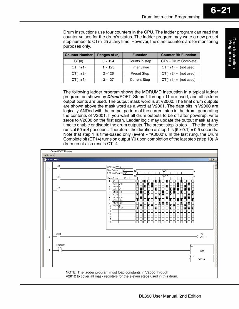
Drum instructions use four counters in the CPU. The ladder program can read thecounter values for the drum’s status. The ladder program may write a new presetstep number to CT(n+2) at any time. However, the other counters are for monitoringpurposes only.
Counter Number Ranges of (n) Function Counter Bit Function
CT(n) 0 -- 124 Counts in step CTn = Drum Complete
CT( n+1) 1 -- 125 Timer value CT(n+1) = (not used)
CT( n+2) 2 --126 Preset Step CT(n+2) = (not used)
CT( n+3) 3 --127 Current Step CT(n+1) = (not used)
The following ladder program shows the MDRUMD instruction in a typical ladderprogram, as shown by DirectSOFT. Steps 1 through 11 are used, and all sixteenoutput points are used. The output mask word is at V2000. The final drum outputsare shown above the mask word as a word at V2001. The data bits in V2000 arelogically ANDed with the output pattern of the current step in the drum, generatingthe contents of V2001. If you want all drum outputs to be off after powerup, writezeros to V2000 on the first scan. Ladder logic may update the output mask at anytime to enable or disable the drum outputs. The preset step is step 1. The timebaseruns at 50 mS per count. Therefore, the duration of step 1 is (5 x 0.1) = 0.5 seconds.Note that step 1 is time-based only (event -- “K0000”). In the last rung, the DrumComplete bit (CT14) turns on output Y0 upon completion of the last step (step 10). Adrum reset also resets CT14.
DirectSOFT Display
NOTE: The ladder program must load constants in V2000 throughV2012 to cover all mask registers for the eleven steps used in this drum.

1