droplet motion in a microconfined shear flow via a three
TRANSCRIPT

Droplet motion in a microconfined shear flow via a three-dimensionalspectral boundary element method
Mohammad A. Khan and Yechun Wanga�
Department of Mechanical Engineering, North Dakota State University, Dept. 2490,P.O. Box 6050, Fargo, North Dakota 58108, USA
�Received 23 May 2010; accepted 17 November 2010; published online 9 December 2010�
A 3D spectral boundary element method is employed to compute the dynamics of a single dropletin a microconfined shear flow. Comparisons have been made for the motion of an initially sphericaldroplet near a single wall and that between two parallel plates. Investigations are conducted for theinfluences of the capillary number, viscosity ratio, and initial location of the droplet on the dropletdeformation, orientation, velocities, as well as the transition between the initial rapid deformationand the subsequent relaxation stage. Computational results for the deformation and velocities arecompared with analytical predictions. It is found that the analytical predictions are limited for smalldeformations, large droplet-wall distances, and near equiviscous droplets. © 2010 AmericanInstitute of Physics. �doi:10.1063/1.3525357�
I. INTRODUCTION
The fundamental study on the motion of a neutrallybuoyant droplet in a low-Reynolds-number shear flow nearsolid walls can be traced back to 1980s with applications inlubrication technologies,1,2 where the existence of journalbearing walls significantly influences droplet-containing lu-bricants. More recently, technologies utilizing nanoliter sizeddroplets have been developed �e.g., microfluidics� which sig-nificant applications in biochemical processes, biomedicalresearch, and clinical studies, including enzymatic analysis,DNA analysis, and disease diagnosis.3–10 To provide funda-mental understanding of the motion of droplets in the afore-mentioned systems, thorough investigations on the nature ofdroplet motion near the vicinity of a microfluidic wall arethus demanded. Investigations have been focused on the mo-tion of a droplet between two parallel plates employing thefollowing dimensionless parameters: �i� capillary numberCa=�Ga /� where � is the viscosity of the suspending fluid,a the radius of the undeformed droplet, G the shear rate, and� the surface tension at the droplet interface; �ii� the viscos-ity ratio � between the droplet and the suspending fluid; �iii�the distance between the droplet and one of the plates nor-malized by the droplet size; �iv� the gap between plates �nor-malized by the droplet size�. Numerical work and experi-mental studies have been devoted to droplet moving alongthe center line of the gap between the parallel plates.11–16
Larger deformation is observed for droplet in shear flow con-fined by parallel plates than unconfined flows.11,12 An in-crease in droplet deformation is observed for decreasing gapwidth. The droplet is found to orient toward the flowdirection.13 For moderate capillary numbers, droplets with aviscosity ratio ��1 display an “overshoot” in the deforma-tion at early stage of the process for small gaps. For dropletwith ��1, overshoots in droplet deformation takes place forlarge gaps.14 Critical capillary numbers �Cac�, above which
the droplet will break up, are found as a function of the gapwidth. For capillary numbers smaller than the critical value,the equilibrium droplet deformation shows a linear relationwith the capillary number.15 The critical capillary numbersare experimentally found to be influenced by gap width aswell as the viscosity ratio �.12,16
Few studies have investigated the motion of a dropletmoving near a single solid wall in shear flow or the casewhen the droplet is released at a location which deviatesfrom the centerline of the gap, although these cases can helpus understand the migration of droplet perpendicular to thesolid wall. Theoretical work by Leighton and Acrivos17 ex-amined the lift on a nondeformable spherical particle in ashear flow confined by a single plate. Scaled with the longi-tudinal drag, the lift was found to be linear with the Rey-nolds number. The authors concluded that the lift as a resultof the inertia in a low-Reynolds-number flow can be ignoreddue to the small magnitude. However their focus was onspherical particles hence the lateral migration due to particledeformation was not investigated. Based on Taylor’s smalldeformation theory, Shapira and Haber2 derived the dropletdeformation and drag force as a function of capillary num-ber, viscosity ratio and droplet-to-wall distance for a dropletmoving near a single wall or between parallel plates. Smartand Leighton, Jr.18 experimentally investigated the motionand deformation of a droplet with viscosity ratio �=0.08 in aCouette flow. Uijttewaal et al.19,20 investigated the dropletlateral and longitudinal migration near a single solid wall inshear flow using a boundary integral method with triangulardiscretization. They compared the numerical solution for themigration velocities with analytical predictions. However,the droplet deformation presented in their study was basedon a quasistatic assumption. Somewhat related are studies forthe droplet motion in a Poiseuille flow between parallelplates. The results for droplet motion in close vicinity to oneof the plate could be valuable since the flow close to theplate could be considered linear. For example, Griggs et al.21
numerically investigated the motion of droplet subject to aa�Electronic mail: [email protected].
PHYSICS OF FLUIDS 22, 123301 �2010�
1070-6631/2010/22�12�/123301/13/$30.00 © 2010 American Institute of Physics22, 123301-1

low-Reynolds number Poiseuille flow between parallel platesunder the influence of the capillary number, viscosity ratio,gap width, as well as the initial location of the droplet in thegap. They found that for droplet placed off the centerline,regardless of the initial location, capillary number, or viscos-ity ratio, deformable droplets tend to migrate away from theplate nearer to the droplet. Nonmonotonic relation is ob-served between the migration velocity of the droplet awayfrom the wall and the viscosity ratio for 2���10.
In this study, a 3D spectral boundary element method is,for its first time, employed to investigate the behavior of adeformable droplet driven to move via a low-Reynolds-number shear flow near a single solid wall. The purposes ofthe current study is to �i� validate the successful applicationof the recently developed 3D spectral boundary elementmethod, a high-order boundary integral method, on dropletmotion in a wall-bounded shear flow, �ii� provide numericalevidence on the justification for neglecting the solid bound-ary far from the droplet in numerical studies, since in experi-ments two plates are needed to create the shear flow, e.g.,using a Couette device, and �iii� investigate the influence ofcapillary number, viscosity ratio, and initial location of thedroplet on the droplet deformation and migration velocities.We emphasize that different from previous numerical studieswe employ a spectral method which leads to higher accuracyand exponential convergence.
II. MATHEMATICAL FORMULATION
We consider that a neutrally buoyant droplet with viscos-ity �� is suspended in another immiscible fluid with viscos-ity �, as shown in Fig. 1. Far from the droplet a shear flowwith shear rate G is applied. The surface tension � of thedroplet interface is assumed constant. The initially sphericaldroplet is released with its centroid at a distance zc0 to thesolid wall Sw. In this work, we use the radius of an unde-formed spherical droplet a as the length scale and the viscoustime scale 1 /G as the time scale. The velocity is scaled withaG. The parameters that influence the droplet behavior arethe capillary number Ca=�Ga /�, viscosity ratio �, and theinitial distance between the solid wall and the droplet cen-troid zc0. The droplet deformation is quantified by defining
D =L − S
L + S, �1�
where L is the length of the longest axis of the droplet and Sis the shortest as shown in Fig. 1. Both L and S are measured
from the center of the mass of the droplet. The droplet ori-entation could be described using the orientation angles �L
and �S, which are defined by the angle between the long axisand the negative x axis and the angle between the short axisand the positive x axis, respectively. Due to the shear flowand the deformation of the droplet itself, the droplet migrateswith a velocity which is composed by a velocity along thesolid wall �Ux� and a velocity perpendicular to the wall �Uz�.
For a micron sized droplet, the inertia may be ignoreddue to the low-Reynolds number. Due to the low-Reynoldsnumber �i.e., small size and velocity�, viscous fluids �e.g.,PDMS or silicone oil� are typically used to create a moderatevalue for the capillary number. The governing equations arethus the Stokes equation and the continuity,
� · � = − �p + c�2u = 0 , �2�
� · u = 0, �3�
where c=1 for the suspending fluid and c=� for the fluid inthe droplet.
The boundary conditions on the droplet interface are
u = u1 = u2, �4�
�f � f2 − f1 =1
Ca��S · n�n , �5�
where the subscripts “1” and “2” represent the flow insidethe droplet and the suspending fluid, respectively. The unitnormal is defined to point into the suspending fluid and isdesignated as n. The curvature is thus expressed as �S ·n. Forthe boundary over the solid plate, the no-slip condition ap-plies, u=0. The undisturbed velocity �u� and stress �f� ofshear flow are applied as
u = �z,0,0� , �6�
f = � · n . �7�
The governing equations and boundary conditions couldbe transformed into boundary integral equations �BIE�.22 Wederive that the velocity at an arbitrary point x0 on the dropletinterface or on the solid wall Sw satisfies the followingboundary integral equation:
�u�x0� − �0u�x0�
= − �
�S · ��f − f� − T · �u�1 − �� − u� · ndS
− �Sw
�S · �f2 − f� − T · �u2 − u� · n�dS , �8�
where �=4��1+�� and 4� for x0 on and the solid bound-ary, respectively; �0=4� for all boundaries. Kernel S is thefundamental solution for the Stokes equations and T is theassociated stress.
xy
z
u∞
nλμ
μ
γ
Γ
Sw
C
zc
L SθL θS
FIG. 1. Illustration for a droplet moving near a solid wall in shear flow.
123301-2 M. A. Khan and Y. Wang Phys. Fluids 22, 123301 �2010�

III. NUMERICAL METHOD
Details for the spectral discretization, mesh redistribu-tion, and interfacial smooth schemes can be found in Wangand Dimitrakopoulos.23 Nevertheless for the completeness ofthis study, in this section we summarize our numerical ap-proach, address criteria for parameter selections, and presentthe convergence test results for the current problem.
The droplet interface is discretized into either six or tenquadrilateral spectral elements as shown in Figs. 2�a� and2�b� using cube projection. The surface of the solid wall iscomposed of a central square element surrounded by threerows of four sectoral elements as shown in Fig. 2�c�. Thelength of the center square element and the outer radius of
each row of sectors are a, 2a, 5a, and 10a, respectively�where a is the radius of an undeformed droplet�. The centerof the solid surface is always in alignment with the dropletcentroid. Computations have been made for the wall radius5�R /a�20, where R denotes the radius of the solid walland droplet-wall distance 1.02�zc0 /a�10. The relative er-rors of droplet deformation and velocities are calculated us-ing values for R=20a as the base. We found that the relativeerrors for all deformation and velocities when R 10a areless than O�10−4�. Hence, although the solid wall should ex-tend to infinity, we define in this numerical study a wallradius ten times the undeformed droplet radius for the solidwall.
The geometric variables on each element are discretizedvia Lagrange interpolations using two parametric variableson a square interval �−1,1�2. The basis points for the para-metric variables are zeros of NB-order orthogonal polynomi-als �i.e., spectral points�. The geometric and physical infor-mation on each discretized node is then substituted into theboundary integral equations. By rearrangement and collec-tion of terms, a linear system of algebraic equations relatingthe velocity u and normal stress f is formed u=Af+Bu. Thematrices A and B are given by the integration of the kernelsS and T and the basis function. The integrations are obtainedvia Gauss quadrature using Legendre and Lobatto points.A fourth-order Runge–Kutta algorithm with a time step of5�10−4 is used for the time evolution of the interface geom-etry �x� via the kinematic condition given by
dx
dt= �u · n�n + Utt , �9�
Ut = ct�u · t� + �1 − ct��uc · t� , �10�
where t is a unit tangent vector on the interface and uc is thevelocity of the droplet centroid. The interface evolution isdetermined by the first term on the right hand side of Eq. �9�,while the second term utilizes the velocity tangent to theinterface for mesh redistribution. Parameter ct �0�ct�1� isemployed to avoid severe grid distortion due to the move-ment of droplet centroid. In addition, a first-order smoothingscheme is applied for better stability of the numericalmethod. Details for the choice of spectral points, thenumerical implementation of mesh redistribution, and the in-terfacial smoothing scheme can be found in Wang andDimitrakopoulos.23
Convergence tests have been performed to assess theaccuracy of the computational results. The droplet deforma-tion D as well as the lateral velocity Uz have been computedusing NB=7, 9, 11, 13, and 15 spectral points for each ele-ment. Other parameters are Ca=0.2, �=1, and zc0=1.5. Thedroplet interface is composed of NE=6 spectral elements.The relative error in D and Uz is determined using those atNB=15 as the base and is plotted as a function of N=NENB
2 inFig. 3. An exponential convergence has been observed forboth the deformation and the droplet velocity. For the com-putations in this study, NB=11 has been employed whichgives an accuracy in the order of magnitude of 10−4.
(a)
(b)
(c)
FIG. 2. Discretization of geometry for spectral boundary element calcula-tion for a droplet moving near a solid plate in shear flow: �a� six spectralelements are employed on the droplet interface for the case of Ca=0.2,�=1, and zc0=1.5 at time t=8, �b� ten spectral elements on the dropletinterface for Ca=0.3, �=1, and zc0=1.5 at time t=1, and �c� surface of thesolid wall.
123301-3 Droplet motion in a microconfined shear flow Phys. Fluids 22, 123301 �2010�

IV. RESULTS AND DISCUSSION
Employing the 3D spectral boundary element methoddescribed in the previous section, we compute the motion ofan initially spherical droplet in a shear flow after it is re-leased at a distance zc0 to a single solid wall. The dropletmoves along the solid wall due to the exerted shear flowwhile it migrates away from the wall. In this section, we firstcompare the droplet deformation and motion in a vicinity ofa single solid wall with similar situations for a droplet mov-ing closer to one of two parallel plates. Validation has beenmade by comparing our results to both numerical and experi-mental findings in literature. We then investigate and discussthe influence of the capillary number, viscosity ratio, andinitial droplet location on the droplet deformation, orienta-tion, longitudinal velocity, and lateral velocity. In addition,the two stages of droplet behavior, the initial rapid deforma-tion and the subsequent relaxation, have been distinguishedand discussed.
A. Droplet motion between parallel plates
In this work, we focus on the behavior of the droplet ina close vicinity of a stationary solid wall. The effect of anyfaraway wall or plate is ignored. The validity of this assump-tion is concluded via the comparison with computations fordroplet motion in two parallel plates. The boundary integralequation for the case of parallel plates is identical to Eq. �8�.The boundary conditions on the droplet interface also followEqs. �4� and �5�. No-slip conditions are applied for both thetop plate, u= �zplate ,0 ,0�, and the lower plate, u= �0,0 ,0�.The discretization for the top plate is similar to the lowerplate as indicated in Fig. 2�c�.
As shown in Fig. 4, we plot the droplet deformation D,lateral migration velocity Uz, and longitudinal velocity Ux asfunctions of time for droplet moving in two parallel plateswith Lt as the distance between the top plate and the originallocation of the droplet. The separation between the lowerplate and the droplet initial location is always zc0=1.5 in this
section. In Fig. 4, we also include our computation for adroplet moving near a single wall with an initial distancezc0=1.5. For all cases, the capillary number is Ca=0.1 andthe viscosity ratio is �=1. We vary the distance Lt and foundthat droplet deformation monotonically decreases as we in-crease Lt for Lt�10. For Lt 10, the deformation is indepen-dent on Lt and the computational result agrees with that for asingle solid wall. The lateral velocity Uz approaches zero andmaintains negligibly small for a droplet released at the centerof two parallel plates �i.e., Lt=1.5�. As we increase Lt, Uz
10−5
10−4
10−3
10−2
10−1
200 400 600 800 1000 1200
Rel
ativ
eE
rror
inD
and
Uz
N
DUz
FIG. 3. The relative error in the computed deformation D and droplet ve-locity in the z direction vs the number of spectral points employed on thedroplet N=NENB
2 for Ca=0.2, �=1, and zc0=1.5 at time t=4. The conver-gence shown is generated by using NE=6 elements on the droplet andNB=7, 9, 11, and 13. The results for NB=15 are used to determine thenumerical error.
0.00
0.02
0.04
0.06
0.08
0.10
0.12
0.14
0.16
0.18
0 1 2 3 4 5 6
t
(a)
D
parallel plates:
Lt increases single plate
Lt = 1.535
10single plate
1.42
1.44
1.46
1.48
1.50
1.52
1.54
0 1 2 3 4 5 6
t
(c)
Ux
parallel plates:
Lt increases
single wall
Lt = 1.535
1015
single wall
-0.005
0.000
0.005
0.010
0.015
0.020
0.025
0 1 2 3 4 5 6
t
(b)
Lt = 1.5
3
5
10
Lt = 1.5
single plate
Uz
FIG. 4. Transient behaviors of deformation D, lateral velocity Uz, and lon-gitudinal velocity Ux of a droplet moving near a single solid wall and be-tween two parallel plates. The distance between the top plate and the initiallocation of the droplet is denoted as Lt.
123301-4 M. A. Khan and Y. Wang Phys. Fluids 22, 123301 �2010�

monotonically increases for Lt�10. For Lt 10, the compu-tational result for Uz is close to that of a single wall. We alsoplot Uz as a function of the droplet-wall distance zc in Fig. 5.The lateral velocity Uz first increases abruptly and thenslowly decreases as the droplet moves toward the upper wall.For the case when Lt=1.5, Uz is independent on zc and thevalue is negligibly small. If the initial location of the dropletis at the centerline between the two parallel plates, the lon-gitudinal velocity Ux of the droplet centroid is found to bethe undisturbed flow velocity of the suspending fluid at thesame location and is independent on the time. The velocityUx decreases with the increase of Lt for Lt�15. For Lt 15,Ux is computed to be identical with that of a single wall.
For validation we compare our solution to both the com-putational and experimental results by Vananroye et al.13 fora droplet moving in the centerline of the gap created byparallel plates. Figure 6 shows the comparison for Ca=0.2,�=1, and zc0=Lt=1.136 36. Data are measured from Fig.10�a� of Vananroye et al.13 and converted using the timescale and length scale defined in the current study. Good
agreement has been found for the droplet length Lp on thevorticity-velocity plane as defined in Vananroye, Puyvelde,and Moldenaers.16 As shown in Fig. 7 the droplet shapes attime t=1.02 and 4.24 computed in the current study alsodemonstrate good agreement with the experimental imagestaken by Vananroye et al.13 �Fig. 10�b� in their study�.
B. Influence of the capillary number
As the droplet is translating near a solid wall, the dropletundergoes deformation and rotation. We describe the dropletgeometry via droplet deformation D and rotation angles �L
and �S. As shown in Fig. 8, lengths of droplet axes �L and S�,deformation �D�, and orientation angles ��L and �S� havebeen plotted as functions of time after the onset of the shearflow at t=0. The droplet deformation increases drastically atthe beginning and then experiences a slow relaxation afterthe maximum deformation is reached. The sudden increasein the deformation is resulted from the increase of the lengthaxis and the decrease of the short axis. The increment in thelong axis is more prominent than the short axis. In the relax-ation process, the long axis L decreases and the short axis Sincreases slowly. Correspondingly, as it fast deforms thedroplet rapidly rotates toward the flow direction and then thedroplet rotates slowly during the relaxation. The orientationangle for the short axis, �S, increases to its maximum andthen slowly decreases back, however, the angle for the longaxis, �L, continues to decrease slowly after the initial rapiddecreasing. A variety of capillary numbers is employed in thecomputation. Results for three capillary numbers Ca=0.05,0.1, and 0.2 are presented in Fig. 8. The droplet experienceslarger deformation at larger values for Ca. We plot in Fig. 9
0.000
0.005
0.010
0.015
0.020
0.025
1.49 1.5 1.51 1.52 1.53 1.54 1.55 1.56 1.57 1.58 1.59 1.6
zc
Uz
parallel plates:
Lt = 3
Lt = 5
Lt = 35
10single wall
FIG. 5. Lateral velocity Uz as a function of droplet-wall distance zc for adroplet moving near a single solid wall and between two parallel plates. Thedistance between the top plate and the initial location of the droplet isdenoted as Lt.
0.80
1.00
1.20
1.40
1.60
1.80
0 1 2 3 4 5 6 7 8 9
t
Lp
numerical solutionVananroye, 2008, experimentVananroye, 2008, numerical
FIG. 6. Droplet length Lp as a function of time t for Ca=0.2, �=1, andzc0=Lt=1.136 36. Also included are the experimental measurements andnumerical results by Vananroye et al. �Ref. 13�.
(a)
(b)
FIG. 7. Numerically computed droplet geometries at time t=1.02 and 4.24for Ca=0.2, �=1, and zc0=Lt=1.136 36. Good agreement has been found bycomparing to Figs. 10�b1� and 10�b2� of Vananroye et al. �Ref. 13�.
123301-5 Droplet motion in a microconfined shear flow Phys. Fluids 22, 123301 �2010�

the deviation of the deformation D from that of a fully re-laxed droplet Dzc at the same location for the droplet centroidas a function of time. The abrupt decrease in the deformationdifference indicates the beginning of the relaxation process.�Dzc is obtained by computing the deformation of a dropletreleased at zc0=1.3.� Figure 8�b� and more clearly Fig. 9show that the maximum deformation is reached earlierand the relaxation process starts earlier for smaller capillarynumbers.
The lateral migration velocity of the droplet Uz is ob-served to behave similarly to the deformation D. As shown inFig. 10�a�, the lateral velocity increases rapidly to reach itsmaximum immediately after the onset of the shear flow, andthen the velocity decreases during the relaxation. As shownin Fig. 11�a�, the lateral velocity Uz increases with the in-
0.70
0.80
0.90
1.00
1.10
1.20
1.30
1.40
1.50
0 2 4 6 8 10 12 14 16
Lan
dS
t
(a)Ca = 0.05
0.10.2LS
0.00
0.05
0.10
0.15
0.20
0.25
0.30
0 2 4 6 8 10 12 14 16
t
(b)
D
Ca = 0.050.10.2
30.0
35.0
40.0
45.0
50.0
55.0
60.0
65.0
70.0
0 2 4 6 8 10 12 14 16
θ Lan
dθ S
t
(c)Ca = 0.05
0.10.2θL
θS
FIG. 8. The time evolution of �a� long L and short S axes of droplet, �b� thedeformation D, and �c� the orientation of the long and short axes �L and �S.Three capillary numbers are included for comparison: Ca=0.05, 0.1, and0.2. For all cases, �=1 and zc0=1.5.
10−8
10−7
10−6
10−5
10−4
10−3
10−2
10−1
100
0 0.5 1 1.5 2 2.5 3 3.5 4 4.5
|D−
Dzc|
t
Ca = 0.050.10.2
FIG. 9. Deviation of the droplet deformation from the relaxation deforma-tion D−Dzc as a function of time. Three capillary numbers are included forcomparison: Ca=0.05, 0.1, and 0.2. For all cases, �=1 and zc0=1.7.
0.000
0.005
0.010
0.015
0.020
0.025
0.030
0.035
0.040
0 2 4 6 8 10 12 14
t
(a)
Uz
Ca = 0.050.10.2
1.400
1.450
1.500
1.550
1.600
1.650
1.700
1.750
1.800
1.850
0 2 4 6 8 10 12 14
t
(b)
Ux
Ca = 0.050.10.2
FIG. 10. Droplet centroid velocity as a function of time t: �a� the lateralvelocity Uz and �b� the longitudinal velocity Ux. Ca=0.05, 0.1, and 0.2. Forall cases, �=1 and zc0=1.5.
123301-6 M. A. Khan and Y. Wang Phys. Fluids 22, 123301 �2010�
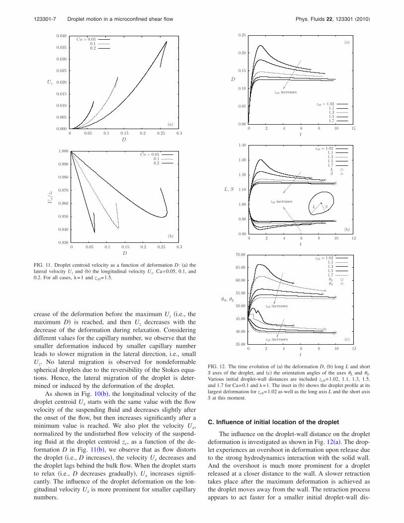
crease of the deformation before the maximum Uz �i.e., themaximum D� is reached, and then Uz decreases with thedecrease of the deformation during relaxation. Consideringdifferent values for the capillary number, we observe that thesmaller deformation induced by smaller capillary numberleads to slower migration in the lateral direction, i.e., smallUz. No lateral migration is observed for nondeformablespherical droplets due to the reversibility of the Stokes equa-tions. Hence, the lateral migration of the droplet is deter-mined or induced by the deformation of the droplet.
As shown in Fig. 10�b�, the longitudinal velocity of thedroplet centroid Ux starts with the same value with the flowvelocity of the suspending fluid and decreases slightly afterthe onset of the flow, but then increases significantly after aminimum value is reached. We also plot the velocity Ux,normalized by the undisturbed flow velocity of the suspend-ing fluid at the droplet centroid zc, as a function of the de-formation D in Fig. 11�b�, we observe that as flow distortsthe droplet �i.e., D increases�, the velocity Ux decreases andthe droplet lags behind the bulk flow. When the droplet startsto relax �i.e., D decreases gradually�, Ux increases signifi-cantly. The influence of the droplet deformation on the lon-gitudinal velocity Ux is more prominent for smaller capillarynumbers.
C. Influence of initial location of the droplet
The influence on the droplet-wall distance on the dropletdeformation is investigated as shown in Fig. 12�a�. The drop-let experiences an overshoot in deformation upon release dueto the strong hydrodynamics interaction with the solid wall.And the overshoot is much more prominent for a dropletreleased at a closer distance to the wall. A slower retractiontakes place after the maximum deformation is achieved asthe droplet moves away from the wall. The retraction processappears to act faster for a smaller initial droplet-wall dis-
0.000
0.005
0.010
0.015
0.020
0.025
0.030
0.035
0.040
0 0.05 0.1 0.15 0.2 0.25 0.3
D
(a)
Uz
Ca = 0.050.10.2
0.930
0.940
0.950
0.960
0.970
0.980
0.990
1.000
0 0.05 0.1 0.15 0.2 0.25 0.3
Ux/z
c
D
(b)
Ca = 0.050.10.2
FIG. 11. Droplet centroid velocity as a function of deformation D: �a� thelateral velocity Uz and �b� the longitudinal velocity Ux. Ca=0.05, 0.1, and0.2. For all cases, �=1 and zc0=1.5.
0.00
0.05
0.10
0.15
0.20
0.25
0 2 4 6 8 10 12
t
(a)
D
zc0 increases
zc0 = 1.021.11.31.51.7
0.80
0.90
1.00
1.10
1.20
1.30
1.40
0 2 4 6 8 10 12
t
(b)
L, S
zc0 increases
L S
zc0 = 1.021.11.31.51.7LS
35.00
40.00
45.00
50.00
55.00
60.00
65.00
70.00
0 2 4 6 8 10 12
t
(c)
θS, θL
zc0 increases
zc0 increases
zc0 = 1.021.11.31.51.7θL
θS
FIG. 12. The time evolution of �a� the deformation D, �b� long L and shortS axes of the droplet, and �c� the orientation angles of the axes �L and �S.Various initial droplet-wall distances are included zc0=1.02, 1.1, 1.3, 1.5,and 1.7 for Ca=0.1 and �=1. The inset in �b� shows the droplet profile at itslargest deformation for zc0=1.02 as well as the long axis L and the short axisS at this moment.
123301-7 Droplet motion in a microconfined shear flow Phys. Fluids 22, 123301 �2010�

tance. Figure 12�b� shows that the lengths of both axes ex-perience rapid change upon release �i.e., the long axis elon-gates while the short axis shrinks� followed by a slowerretraction. The long axis deformation is shown to contributemore in the deformation overshoot. As shown in Fig. 13 apointing tip is formed near the wall on the droplet interface,which is responsible for the overshooting peaks in the longaxis and the deformation. It is also evident that droplets withbetter deformability tend to have greater overshoot near thesolid wall. The overshoot and relaxation of the droplet defor-mation are also observed in numerical computations fordroplets confined in two parallel plates �e.g., Janssen andAnderson,11 Griggs et al.�.21 For orientation angles, as shownin Fig. 12�c� we observe that for all initial distances zc0, �S
first increases rapidly and then gradually decreases. For thelong axis orientation angle �L, we found that for a largerdistance to the wall �L undergoes a fast decrease initiallyfollowed by a slow decrease. However, starting at a smalldistance to the wall, �L increases initially and some noise inthe data value have been shown followed by a slow decrease.The noise in orientation angle calculations resulted from thenature of numerical computation, which is also observed byJanssen and Anderson11 in their computations. The behaviorof droplet deformation and orientation angles show that in-stantly upon the release, the droplet rapidly deforms and ro-tates. After the maximum deformation is achieved the droplettends to rotate backward while the deformation slowly re-
duces. The magnitudes of the variations in the deformationand orientation angles are more prominent when the initiallocation of the droplet is closer to the wall.
The droplet deformation D as a function of its lateralposition zc is plotted in Fig. 14 for two cases �i� capillarynumber Ca=0.2 and viscosity ratio �=0.2 and �ii� Ca=0.1and �=1. A variety of initial locations has been examined.We observe that the initially spherical droplet shows a sub-stantial deformation without much lateral migration awayfrom the wall. As the droplet migrates away from the wallrelaxation in deformation takes place. We found in the relax-ation process, the relation between the droplet deformation Dand the lateral position zc is independent on the initial loca-tion of the droplet. In Fig. 14 we include the analytical pre-dictions of the droplet deformation based on the formuladerived by Shapira and Haber2 which accounts for the modi-fication to the droplet deformation in shear flow due to theexistence of a single solid wall nearby. The analytical resultsagree well with the numerical calculations when the dropletdeformation retracts to small values, i.e., when the dropletmigrates further away from the wall or the capillary numberis small. The discrepancy at large deformation lies in the factthat the analytical study of Shapira and Haber2 is primarilybased on the small deformation theory of Taylor,24 as well asthe fact that their analytical formula is only valid for largedistances between the droplet and the wall.1
The relative difference between the deformation of adroplet near the solid wall and that of a droplet freely sus-pended in shear flow, �D−D� /D, is plotted as a function ofthe droplet-wall distance zc in Fig. 15. We consider only therelaxation process of the droplet since as found in Fig. 14 therelaxation deformation is independent on the initial location.It is found that the existence of a solid wall amplifies thedroplet deformation significantly. Among the cases plotted inFig. 15, about 46% increase in the droplet deformation isobserved for �=1 if the droplet is located zc=1.25 from thewall. The droplet deformation decreases as zc increases andeventually becomes identical with the deformation of a drop-let freely suspended at around zc=5 for all cases. We also
(a)
(b)
FIG. 13. Shapes of droplet at its largest deformation. �a� Ca=0.1, �=1,zc0=1.02, and t=1.4; �b� Ca=0.2, �=1, zc0=1.02, and t=1.8.
0.05
0.10
0.15
0.20
0.25
0.30
0.35
1 1.2 1.4 1.6 1.8 2 2.2
zc
D
Ca = 0.2, λ = 0.1
Ca = 0.1λ = 1
SBEMShapira & Haber, 1990
FIG. 14. Deformation D as a function of droplet centroid location zc forzc0=1.1, 1.3, 1.5, 1.7, and 2. Two cases are presented: �i� Ca=0.2 and�=0.1 and �ii� Ca=0.1 and �=1. Also included are analytical predictions ofO�zc
−3� by Shapira and Haber �Ref. 2� for comparison.
123301-8 M. A. Khan and Y. Wang Phys. Fluids 22, 123301 �2010�

found that the relative difference in the deformation is inde-pendent on the capillary number Ca. As shown in Fig. 15, for�=0.1, curves for a variety of Ca overlap. The independenceon Ca is also found for other viscosity ratios �which are notincluded in the Figure�. Figure 15 also shows that the ampli-fication effect of the existence of a wall is more prominentfor larger � if ��1 for all zc values. More discussion on theinfluence of � can be found in Sec. IV D.
Although the deformation during relaxation is indepen-dent on the initial droplet location, the time an initiallyspherical droplet spent before the relaxation stage is reachedcan be related to the initial location. As shown in Fig. 16where the transient deviation of the deformation from that ofa fully relaxed droplet D−Dzc is plotted for a variety ofinitial locations, a droplet with a smaller initial distance to-ward the wall tends to reach the relaxation stage earlier.
The wall effect is also more substantial for the lateralmigration velocity Uz, which instantly increases to its maxi-mum upon release. The maximum Uz is larger if the initialdroplet location is closer to the wall. After the maximum Uz
is reached, the lateral velocity starts to decrease. Figure 17plots Uz as a function of zc at a variety of droplet initiallocations for a droplet with Ca=0.1 and �=1 and that withCa=0.2 and �=0.1. We observe that, independent on theinitial location, Uz always increases abruptly, which makesthe droplet to drift away from the solid wall rapidly. And theslower decrease in Uz is also independent on the initial loca-tion of the droplet. The decreasing behavior of Uz is propor-tional to zc
−2 as predicted by Chan and Leal.25 Curves utiliz-ing the zc
−2 dependence formula of the velocity Uz by Chanand Leal25 has been plotted in Fig. 17. A small discrepancyhas been observed and the analytical solution by Chan andLeal25 shows an overestimation comparing to our numericalsolution. We also show the best zc
−2 fitting on the same figurefor the decreasing lateral velocity Uz and find that the bestfitting can always be expressed as
Uz,decreasing = kUz,CL, �11�
where k is a coefficient which is dependent on the capillarynumber and the viscosity ratio. Uz,CL denotes the analyticalprediction by Chan and Leal. For the two cases presented,k=0.926 76 and 0.903 67 for the upper and lower curves,respectively.
In Fig. 18, the longitudinal velocity Ux is plotted as afunction of droplet centroid location zc for four different ini-tial locations of a droplet with Ca=0.1 and 0.2, and �=1. Weobserve that the increasing part of the velocity Ux is almostindependent on the initial location of the droplet and theycan be described by the single curve as a function of thedroplet centroid location zc. It can also be observed that thecurves for increasing Ux with different Ca tend to convergeas zc increases. The dependency on Ca for Ux is only promi-nent when the droplet is very close to the wall. The analyticalprediction for the increasing Ux by Shapira and Haber2 isalso included. Good agreement has been found between ournumerical solution and the analytical prediction. The analyti-cal solution slightly underestimates the increasing Ux forlarger capillary numbers in close vicinity of the wall.
0.00
0.10
0.20
0.30
0.40
0.50
0 1 2 3 4 5 6
(D−
D∞
)/D
∞
zc
Ca= 0.3, λ = 0.01Ca= 0.05, λ = 0.1
Ca=0.1, λ = 0.1Ca= 0.2, λ = 0.1
Ca=0.1, λ = 1
FIG. 15. Relative difference in deformation, �D−D� /D, as a function ofthe droplet-wall distance zc. D is the steady-state deformation of a dropletfreely suspended in an unbounded shear flow. Curves are included for avariety of capillary numbers and viscosity ratios.
10−8
10−7
10−6
10−5
10−4
10−3
10−2
10−1
100
0 0.5 1 1.5 2 2.5 3 3.5
|D−
Dzc|
t
zc0 = 1.52.02.5
FIG. 16. Deviation of the droplet deformation from relaxation deformationD−Dzc as a function of time. Various initial droplet-wall distances areincluded zc0=1.5, 2.0, and 2.5 for Ca=0.2 and �=0.1.
0.00
0.02
0.04
0.06
0.08
0.10
0.12
1 1.2 1.4 1.6 1.8 2 2.2
zc
Uz Ca= 0.2, λ = 0.1
Ca= 0.1λ = 1
numerical solutionChan & Leal, 1979
best fitting
FIG. 17. Migration velocity Uz as a function of droplet centroid location zc
for zc0=1.1, 1.3, 1.5, 1.7, and 2. Two cases are presented: �i� Ca=0.2 and�=0.1 and �ii� Ca=0.1 and �=1. A best zc
−2 fitting for the decreasing part ofUz is shown. Analytical predictions by Chan and Leal �Ref. 25� are alsoincluded.
123301-9 Droplet motion in a microconfined shear flow Phys. Fluids 22, 123301 �2010�

D. Influence of the viscosity ratio
We plot the droplet deformation D as a function of timet for a variety of viscosity ratios �=0.1, 0.5, 1, 1.5, 5, and 10in Figs. 19�a� and 19�b�. It can be observed that as the vis-cosity ratio increases, the rate of deformation decreasesmonotonically. However the magnitude of the deformation
does not vary with the viscosity ratio monotonically. Themaximum deformation increases with � when ��1.5 asshown in Fig. 19�a�, but decreases as � increases when� 1.5 as shown in Fig. 19�b�. The nonmonotonical behav-ior of the deformation D as a function of viscosity ratio iscontrary to the analytical prediction by Shapira and Haber.2
This is shown in Fig. 20�a�, where we plot the droplet defor-mation D as a function of the viscosity ratio � for a dropletmigrates to the location zc=1.65 and 4.01. The capillarynumber is Ca=0.2. To discount the discrepancy in terms ofcapillary number, we plot the droplet deformation normal-ized by its deformation at �=1. The analytical study byShapira and Haber2 predicts that the deformation increasesmonotonically with � while we observe a maximum defor-mation is achieved around �=1 in the numerical solution.The analytical prediction and numerical results agree witheach other for ��O�1�. In addition, the numerical solutionshows that for ��1.5 the deformation is smaller for a drop-let closer to the wall while for ��1.5 the deformation islarger for a droplet closer to the wall. This finding is inqualitative agreement with the analytical prediction shown asdotted lines in Fig. 20. Comparisons have also been madewith the analytical solution for a small capillary number
0.60
0.80
1.00
1.20
1.40
1.60
1.80
2.00
1 1.1 1.2 1.3 1.4 1.5 1.6 1.7 1.8 1.9 2
zc
UxCa = 0.2
Ca = 0.1
numerical solutionShapira & Haber, 1990
FIG. 18. Longitudinal velocity Ux as a function of droplet centroid locationzc. Ca=0.1 and 0.2, �=1, and zc0=1.1, 1.3, 1.5, and 1.7. Also included as thedotted line is the analytical prediction by Shapira and Haber �Ref. 2� for theincreasing Ux.
0.00
0.05
0.10
0.15
0.20
0.25
0.30
0 2 4 6 8 10 12
t
(a)
D
λ increases
λ = 0.10.5
11.5
0.00
0.05
0.10
0.15
0.20
0.25
0.30
0 2 4 6 8 10 12
t
(b)
D
λ = 1.55
10
FIG. 19. Deformation D as a function of time t. Ca=0.2, �=0.1, 0.5, 1, 1.5,5, and 10, and zc0=1.5.
0.70
0.75
0.80
0.85
0.90
0.95
1.00
1.05
1.10
1.15
0.1 1 10
D/D
λ=
1
λ
(a)
zc = 1.654.01
Shapira & Haber, 1990
0.70
0.75
0.80
0.85
0.90
0.95
1.00
1.05
1.10
1.15
0.1 1 10
D/D
λ=
1
λ
(b)
numerical solutionShapira & Haber, 1990
FIG. 20. Deformation D normalized by the deformation at �=1 as a func-tion of viscosity ratio � for �a� Ca=0.2 and zc0=1.65 and 4.01, and �b�Ca=0.05 and zc0=1.61. The numerical results are plotted as circles andtriangles connected with solid lines. Analytical solutions using the deriva-tion by Shapira and Haber �Ref. 2� are included as dotted curves.
123301-10 M. A. Khan and Y. Wang Phys. Fluids 22, 123301 �2010�

Ca=0.05 as shown in Fig. 20�b�. It shows that for small tointermediate viscosity ratios the numerical solution agreeswell with the analytical solution. However, the analyticalwork still overpredicts the deformation at large �. We believethat besides the small deformation theory that the analyticalmethod adopts, the discrepancy is also incurred by their as-sumption of a constant orientation angle �L=45°. Numericalresults show in Fig. 21 that the deviation from 45° for both�L and �S is more significant for larger �. Our findings are inqualitative agreement with the numerical study by Griggs etal.21 who showed the nonmonotonic deformation of a dropletin a Poiseuille flow between parallel plates regarding theviscosity ratio over 0.5���10.
The viscosity ratio is also found to influence the timethat a droplet spends before the relaxation stage is reached.As shown in Fig. 22, the difference between the droplet de-formation D and that for a fully relaxed droplet Dzc is plottedas a function of time. For ��1, the time needed to reach therelaxation stage increases as we increase the viscosity ratio
�, while for � 1, a decrease in the time is observed as �
increases. The maximum time needed to reach relaxation isfound around �=1.
On the contrary, the lateral velocity Uz and longitudinalvelocity Ux of the droplet decrease monotonically with theincrease of the viscosity ratio as shown in Fig. 23 where weplot the velocities as functions of droplet centroid zc for�=0.1, 1, 2.5, and 5, and Ca=0.2. The monotonic behaviorof Uz differs from the analytical solution by Chan and Leal,25
which predicts that the lateral migration velocity Uz in-creases with the viscosity ratio, as shown in Fig. 24. Thediscrepancy is also found by Uijttewaal and Nijhof20 bycomparing their numerical solution to the analytical predic-tion. The prediction by Shapira and Haber on Ux as a func-tion of � qualitatively agrees with our numerical solution asshown in Fig. 25, where we plot the longitudinal velocity Ux
normalized by Ux at �=1 to discount the influence of thecapillary number. We observe that for ��O�1� the analyticalresults overestimates the longitudinal velocity Ux whileunderestimation is found for the analytical prediction for��O�1�.
10.0
20.0
30.0
40.0
50.0
60.0
70.0
80.0
0 2 4 6 8 10 12 14 16
θ Lan
dθ S
t
λ decreases
λ = 0.10.5
11.5
510θSθL
FIG. 21. Orientation angles ��L and �S� as a function of time t. Ca=0.2,�=0.1, 0.5, 1, 1.5, 5, and 10, and zc0=1.5.
10−7
10−6
10−5
10−4
10−3
10−2
10−1
100
0 0.5 1 1.5 2 2.5 3 3.5 4 4.5
|D−
Dzc|
t
λ = 0.10.51.01.55.0
FIG. 22. Deviation of the droplet deformation from the relaxation deforma-tion D−Dzc as a function of time. A variety of viscosity ratios is includedfor comparison: �=0.1, 0.5, 1.0, 1.5, and 5.0. For all cases,Ca=0.2 and zc0=1.7.
0.00
0.01
0.02
0.03
0.04
0.05
1.45 1.5 1.55 1.6 1.65 1.7 1.75 1.8
zc
(a)
Uz
λ = 0.1
1
2.5
5
1.40
1.45
1.50
1.55
1.60
1.65
1.70
1.75
1.45 1.5 1.55 1.6 1.65 1.7 1.75 1.8
zc
(b)
Ux
λ increases
λ = 0.11
2.55
FIG. 23. The lateral and longitudinal velocities �Uz and Ux� as functions ofdroplet centroid location zc and the viscosity ratio �. For all cases, thecapillary number is Ca=0.2.
123301-11 Droplet motion in a microconfined shear flow Phys. Fluids 22, 123301 �2010�

V. CONCLUSIONS
The motion of an initially spherical droplet in a shearflow confined by a single solid wall is investigated using a3D spectral boundary element method which benefits fromthe characteristics of spectral methods �i.e., exponential con-vergence and numerical stability as the number of discretiza-tion points increases�. Comparisons have been made for thedroplet motion near a single wall and that between two par-allel plates. It is found that a faraway plate could be ne-glected if it is located at a distance larger than 15 times of thedroplet characteristic length to the droplet. We also validateour numerical method by comparing the results to both nu-merical and experimental studies. The validation shows thatour method is able to describe well the droplet deformation,migration, and translation in microconfined shear flow.
Investigations are conducted for the influences of thecapillary number, viscosity ratio and initial location of thedroplet on the droplet deformation, orientation, lateral veloc-ity, and longitudinal velocity. The droplet behavior can be
divided into two stages after it is released near a solid wall:�i� the initial rapid deformation and �ii� the relaxation pro-cess. In the first stage, the droplet deforms and rotates rapidlywith velocities built up abruptly. And then in the relaxationstage, the change in droplet geometry and velocity slowsdown. Our analysis indicates that the relaxation stage ap-pears later for larger Ca values and larger zc0 values. How-ever, the influence of � on the time needed for a droplet toreach the relaxation stage is more complicated. The maxi-mum time needed is achieved at �=1. Similar to the dropletdeformation in unbounded shear flow, the increase in thecapillary number leads to the increase in the droplet defor-mation D. The existence of a single wall in a close vicinity ofthe droplet creates an overshoot in the increase of the dropletdeformation upon the release of the droplet. The overshoot ismore prominent for larger capillary number and smaller dis-tance between the droplet and the wall. The droplet long axisalways tends to rotate toward the flow direction, while theshort axis rotates rapidly away the flow direction upon re-lease but it tends to slowly rotate back in the relaxation pro-cess. The droplet behavior in the relaxation process is foundto be a function of droplet centroid in the lateral direction,capillary number, and viscosity ratio. The initial location ofthe droplet does not influence the droplet relaxation. Numeri-cal results have been compared to analytical predictions.Agreement has been found that as the droplet moves awayfrom the wall both the deformation D and lateral velocity Uz
decreases and the longitudinal velocity Ux increases. Smalldiscrepancy has been found between the numerical and ana-lytical results due to the assumptions of small deformationand large droplet-wall distance that analytical predictionsemployed. For large Ca values the droplet deformation isfound to reach a maximum around �=O�1� as we increasethe viscosity ratio. Both the lateral velocity and the longitu-dinal velocity decrease with the viscosity ratio monotoni-cally. Disagreement has been found between the numericalresults and analytical predictions for the influence of the vis-cosity ratio on the droplet deformation for ��O�1�, as wellas on the droplet lateral velocity for the entire range of vis-cosity ratio examined.
We conclude that the 3D spectral boundary element for-mulation has been successfully applied to investigate thedroplet motion in microconfined shear flow. Numerical stud-ies are necessary for this type of problem if high accuracy isdesired. The comparison between the numerical and analyti-cal solutions suggests that the analytical predictions are lim-ited for small deformations, large droplet-wall distances, andnear equiviscous droplets. More experimental work is sug-gested to be conducted in the future for the motion of non-equiviscous droplets in a close vicinity of a solid wall, espe-cially for a droplet more viscous than the suspending fluid.
ACKNOWLEDGMENTS
This work was supported by ND EPSCoR and NSF EPSGrant No. 0814442 and NDSU Development Foundation’sCentennial Endowment. Some computations were performedon multiprocessor computers at Teragrid.
0.5
0.6
0.7
0.8
0.9
1.0
1.1
1.2
0.1 1 10
Uz/U
z,λ
=1
λ
numerical solutionChan & Leal, 1979
FIG. 24. Velocity Uz as a function of viscosity ratio � for Ca=0.2 andzc0=1.65. Numerical results are plotted as circles connected with solid lines.The analytical prediction by Chan and Leal �Ref. 25� is also included as thedotted curve.
0.980
0.985
0.990
0.995
1.000
1.005
1.010
1.015
1.020
0.1 1 10
Ux/U
x,λ
=1
λ
numerical solutionShapira & Haber, 1990
FIG. 25. Velocity Uz as a function of viscosity ratio � for Ca=0.2 andzc0=1.65. Numerical results are plotted as circles connected with solid lines.The analytical prediction by Shapira and Haber �Ref. 2� is also included asthe dotted curve.
123301-12 M. A. Khan and Y. Wang Phys. Fluids 22, 123301 �2010�

1M. Shapira and S. Haber, “Low Reynolds number motion of a dropletbetween two parallel plates,” Int. J. Multiphase Flow 14, 483 �1988�.
2M. Shapira and S. Haber, “Low Reynolds number motion of a droplet inshear flow including wall effects,” Int. J. Multiphase Flow 16, 305 �1990�.
3F. Su and K. Chakrabarty, “Microfluidics-based biochips: Technology is-sues, implementation platforms, and design-automation challenges,” IEEETrans. Comput.-Aided Des. 25, 211 �2006�.
4H. Song, J. D. Tice, and R. F. Ismagilov, “A microfluidic system forcontrolling reaction networks in time,” Angew. Chem., Int. Ed. 42, 768�2003�.
5T. M. Squires and S. R. Quake, “Microfluidics: Fluid physics at the nano-liter scale,” Rev. Mod. Phys. 77, 977 �2005�.
6H. A. Stone, A. D. Stroock, and A. Ajdari, “Engineering flows in smalldevices: Microfluidics toward a lab-on-a-chip,” Annu. Rev. Fluid Mech.36, 381 �2004�.
7Y. Tan, J. S. Fisher, A. I. Lee, V. Cristini, and A. P. Lee, “Design ofmicrofluidic channel geometries for the control of droplet volume, chemi-cal concentration, and sorting,” Lab Chip 4, 292 �2004�.
8D. R. Link, S. L. Anna, D. A. Weitz, and H. A. Stone, “Geometricallymediated breakup of drops in microfluidic devices,” Phys. Rev. Lett. 92,054503 �2004�.
9S. Y. Teh, L. H. Hung, R. Lin, and A. P. Lee, “Droplet microfluidics,” LabChip 8, 198 �2008�.
10T. D. Chung and H. C. Kim, “Recent advances in miniaturized microflu-idic flow cytometry for clinical use,” Electrophoresis 28, 4511 �2007�.
11P. J. A. Janssen and P. D. Anderson, “Boundary-integral method for dropdeformation between parallel plates,” Phys. Fluids 19, 043602 �2007�.
12V. Sibillo, G. Pasquariello, M. Simeone, V. Cristini, and S. Guido, “Dropdeformation in microconfined shear flow,” Phys. Rev. Lett. 97, 054502�2006�.
13A. Vananroye, P. J. A. Janssen, P. D. Anderson, P. V. Puyvelde, and P.Moldenaers, “Microconfined equiviscous droplet deformation: Compari-son of experimental and numerical results,” Phys. Fluids 20, 013101�2008�.
14P. J. A. Janssen and P. D. Anderson, “A boundary-integral model for dropdeformation between two parallel plates with non-unit viscosity ratiodrops,” J. Comput. Phys. 227, 8807 �2008�.
15D. Megias-Alguacil, K. Feigl, M. Dressler, P. Fischer, and E. J. Windhab,“Droplet deformation under simple shear investigated by experiment, nu-merical simulation and modeling,” J. Non-Newtonian Fluid Mech. 126,153 �2005�.
16A. Vananroye, P. V. Puyvelde, and P. Moldenaers, “Effect of confinementon droplet breakup in sheared emulsions,” Langmuir 22, 3972 �2006�.
17D. Leighton and A. Acrivos, “The lift on a small sphere touching a planein the presence of a simple shear flow,” Z. Angew. Math. Phys. 36, 174�1985�.
18J. R. Smart and D. T. Leighton, Jr., “Measurement of the drift of a dropletdue to the presence of a plane,” Phys. Fluids A 3, 21 �1991�.
19W. S. J. Uijttewaal, E. J. Hijhof, and R. M. Heethaar, “Droplet migration,deformation, and orientation in the presence of a plane wall: A numericalstudy compared with analytical theories,” Phys. Fluids A 5, 819�1993�.
20W. S. J. Uijttewaal and E. J. Hijhof, “The motion of a droplet subjected tolinear shear flow including the presence of a plane wall,” J. Fluid Mech.302, 45 �1995�.
21A. J. Griggs, A. Z. Zinchenko, and R. H. Davis, “Low-Reynolds-numbermotion of a deformable drop between two parallel plane walls,” Int. J.Multiphase Flow 33, 182 �2007�.
22C. Pozrikidis, Boundary Integral and Singularity Methods for LinearizedViscous Flow �Combridge University Press, New York, 1992�.
23Y. Wang and P. Dimitrakopoulos, “A three-dimentional spectral boundaryelement algorithm for interfacial dynamics in stokes flow,” Phys. Fluids18, 082106 �2006�.
24G. I. Taylor, “The formation of emulsions in definable fields of flows,”Proc. R. Soc. London, Ser. A 146, 501 �1934�.
25P. C.-H. Chan and L. G. Leal, “The motion of a deformable drop in asecond-order fluid,” J. Fluid Mech. 92, 131 �1979�.
123301-13 Droplet motion in a microconfined shear flow Phys. Fluids 22, 123301 �2010�