drop test simulation of a cooker including foam packaging and
TRANSCRIPT
9th International LS-DYNA Users Conference Simulation Technology (4)
18-33
Drop Test Simulation of a Cooker Including Foam Packaging and Pre-stressed Plastic Foil Wrapping
Dan Neumayer
1, Madhukar Chatiri 2, Matthias Höermann
2 1 Bosch-Siemens-Hausgeräte, Traunreut, Germany
2 CADFEM GmbH, Grafing b. Munich, Germany
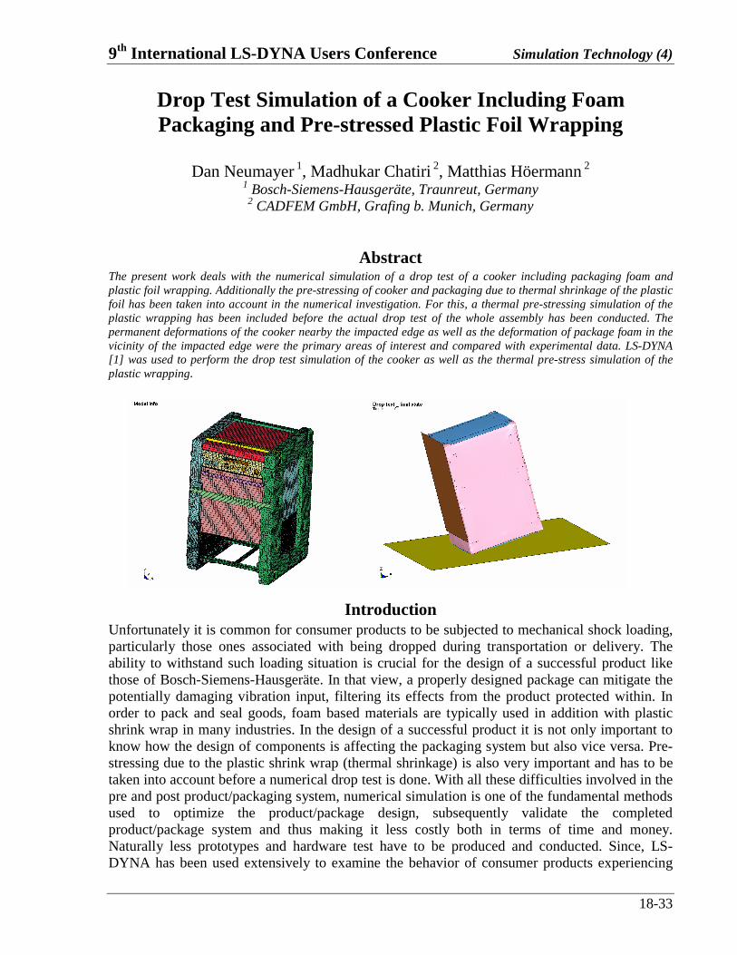
Abstract The present work deals with the numerical simulation of a drop test of a cooker including packaging foam and plastic foil wrapping. Additionally the pre-stressing of cooker and packaging due to thermal shrinkage of the plastic foil has been taken into account in the numerical investigation. For this, a thermal pre-stressing simulation of the plastic wrapping has been included before the actual drop test of the whole assembly has been conducted. The permanent deformations of the cooker nearby the impacted edge as well as the deformation of package foam in the vicinity of the impacted edge were the primary areas of interest and compared with experimental data. LS-DYNA [1] was used to perform the drop test simulation of the cooker as well as the thermal pre-stress simulation of the plastic wrapping.
Introduction Unfortunately it is common for consumer products to be subjected to mechanical shock loading, particularly those ones associated with being dropped during transportation or delivery. The ability to withstand such loading situation is crucial for the design of a successful product like those of Bosch-Siemens-Hausgeräte. In that view, a properly designed package can mitigate the potentially damaging vibration input, filtering its effects from the product protected within. In order to pack and seal goods, foam based materials are typically used in addition with plastic shrink wrap in many industries. In the design of a successful product it is not only important to know how the design of components is affecting the packaging system but also vice versa. Pre-stressing due to the plastic shrink wrap (thermal shrinkage) is also very important and has to be taken into account before a numerical drop test is done. With all these difficulties involved in the pre and post product/packaging system, numerical simulation is one of the fundamental methods used to optimize the product/package design, subsequently validate the completed product/package system and thus making it less costly both in terms of time and money. Naturally less prototypes and hardware test have to be produced and conducted. Since, LS-DYNA has been used extensively to examine the behavior of consumer products experiencing

Simulation Technology (4) 9th International LS-DYNA Users Conference
18-34
mechanical impact loading, the customer wanted to do the numerical simulations to change their previous behavior of prototype experimental testing.
Finite Element Analysis Approach CAD model of the whole assembly unit of the cooker was meshed and a non linear explicit dynamic solutions were performed using LS-DYNA. The FEA model of the whole cooker unit consists of oven, front door, side plates, heating plates, foam packaging, paper cardboard and plastic foil wrapping. In total it was comprised of 154872 explicit shell elements, 125 beams, 156371 solids, 1089 mass elements . The foam packaging was meshed with tetrahedrons. These elements provide a robust solution during large deformation and contact analyses. Also they can be used with automatic tetrahedral mesh generators, thus easing the task of meshing the complex molded geometry typically packaging components exhibit. The cooker components are meshed with shell elements. The impacted side of the foam and side plates were discretised finer compared to other parts of the cooker assembly to capture the deformation more precisely as seen in Fig .1.
Fig. 1.Meshed unit of cooker For the cardboard, elastic material model (Type 1), for plastic foil elastic-plastic-thermal material model (Type 4), which makes the plastic foil shrink onto the cooker assembly, and for the deformable cooker body, piecewise linear plasticity material models (Type 24) are used. Rigid parts are modeled using the rigid material (Type 20) of LS-DYNA. For the foam structures, the material model for isotropic crushable foams (Type 75) was used. Initially for the foam material model, the material parameters, load curves defining uniaxial yield stress/pressure vs. logarithmic volumetric strains from experimental tests (Fig.2.) which were supplied from the foam manufacturer is used. The given curve exhibits the typical behavior of foam with an initial elastic slope followed by a phase of large deformation with less stress increase and at the final end a significant densification. Currently an experimental investigation is ongoing in order to determine reliable dynamical material input data. For this, foam specimens with different densities are tested at various strain rates. Following up, the material model validation will lead to proper description of the foam material at different strain rates and densities.

9th International LS-DYNA Users Conference Simulation Technology (4)
18-35
Fig. 2.Stress – strain curve for foam
The inner component of the cooker, i.e. the oven, has only little deformation during the impact scenario. Consequently the oven parts are assumed to be rigid and modeled as rigid. Questions concerning failure of connectors within the cooker structure is excluded from the numerical investigation. Accordingly, single components of the cooker are connected using constrained nodal rigid bodies (Fig.3.) and several rigid parts in the oven are constrained to a master rigid body.
Fig. 3.Rigid connections
Also, since not all parts are modeled, the total mass of the cooker is adjusted according to experimental measurements by adding discrete mass points. Care is also taken to have a correct centre of gravity in the numerical model according to the experimental measurements (Fig.4). All the parts are given the initial velocity in the required directions according to the experimental test.
Fig. 4.Mass and centre of mass

Simulation Technology (4) 9th International LS-DYNA Users Conference
18-36
Apart from conventional contact definitions such as *contact_automatic_surface_to_surface, *contact_nodes_to_surface etc. which are used to define contact between various parts, special contacts are defined for the edge to edge contact situations.
Thermal pre stressing In the packaging process, cooker and packaging panels are combined and thereafter wrapped with a plastic foil, which shrinks due to thermal heating. Thus a thermal pre-stressing of the whole assembly has been achieved. Consequently the thermal pre-stressing of the assembly is very important before the actual drop test of the whole assembly is performed. The plastic foil is modeled with elastic-plastic material model, with a negative thermal coefficient of expansion (α = -0.00025) which makes it shrink onto the cooker assembly unit when thermal loading is applied (temperature vs. time). By, using the *INTERFACE_SPRINGBACK_LSDYNA card at the end of thermal pre-stressing simulation the stresses and the strains in each parts are written to the dynain file, which should be taken into account during the drop test. The thermal load was applied quasi statically (Fig 5.) so that the dynamics at the end of thermal pre stressing are minimal.
Fig. 5.Thermal load curve
The Energy balance from thermal calculations can be seen in the Fig.6. Due to the thermal shrinkage in the plastic foil the internal energy must become negative whereas the sliding interface energy is positive. Internal and sliding interface energy are almost in the same absolute range, so to say nearly in equilibrium. Only minimal kinetic energy at the end of the thermal pre-stress is observed.
Fig. 6.Energy balance for thermal loading

9th International LS-DYNA Users Conference Simulation Technology (4)
18-37
Also, Fig. 7 shows the von Mises stress in the plastic foil at the final state of the thermal shrinkage. The thermal pre-stressing (von Mises stress) is compared according to the initial experimental observations from the customer.
Fig. 7.von Mises stress in shrinkage plastic foil from the thermal loading
Drop test
After the thermal pre-stressing has been done, the Dynain file which contains the information about the updated nodal co-ordinates, pre-stressing of the parts coming from *INTIAL_STRESS_SOLID, *INITIAL_STRESS_SHELL etc. is taken. Furthermore the mentioned initial and boundary conditions are applied in the required directions as seen in the Fig. 8. The simulation is conducted until the secondary impact of the cooker, i.e. until the opposite edge has impacted the rigid plate as well. Subsequent impacts have a minor influence on the deformation of the impacted edge.
Fig. 8.Boundary and initial conditions
Permanent deformations of the cooker near the impacted edge are calculated as well as the deformation of the foam near the vicinity of the impacted edge. All these simulation results are compared with experimental drop test results and they are in close agreement. The first principal stress on the impacted edge at different time steps can be seen exemplarily in Fig.9.

Simulation Technology (4) 9th International LS-DYNA Users Conference
18-38
Fig. 9.First principal stresses on the impacted edge during the drop test with pre-stressing The energy balance from the drop test results can be seen in the below Fig.10. External work as well as total energy is going down since the moving rigid plate in Fig. 8 is decelerated from the initial velocity to zero.
Fig. 10.Energy balance from drop test The von Mises stress in different parts are checked and can be seen exemplarily in the Fig.11 below.
. Fig. 11.von Mises stress in foam and impacted side plate
The damage done to the foam is compared to the experimental results and can be clearly seen from the below comparison of Fig .12 that the numerical results predict the damage of foam correctly according to the experimental results. Moreover the first principal strains are shown indicating the corresponding failure in tension.

9th International LS-DYNA Users Conference Simulation Technology (4)
18-39
Fig. 12.First principal strains on the impacted edge compared with experimental testing
The plastic strains on the impacted edge can be seen in the below Fig .13 and can be used to check the impacted edge in more detail. Additional plastic strains are observed in the vicinity of the oven support.
Fig. 13. Plastic strains on the impacted edge Also, the remaining displacements (spring back displacements) on the impacted edge which show the permanent deformations on the impacted edge in tests are calculated and the results are in close agreement with experimental measurements. They can be seen exemplarily in the Fig. 14 for certain nodes.
Fig. 14. Spring back displacements on the nodes of impacted edge

Simulation Technology (4) 9th International LS-DYNA Users Conference
18-40
From the above comparison of results it can be said that the numerical simulation results are in good agreement with experimental results and thus helping Bosch-Siemens-Hausgeräte gaining time in the development of an optimized procedure for product/package system.
Conclusions The packaging test of cooker assembly unit including its packaging foam and plastic wrap has been achieved. The thermal pre-stressing of the plastic is included before the numerical impact test was conducted. The simulation results are in good agreement with the experimental drop test results. The foundation for an optimized procedure for product/package design has been achieved.
References
[1] LS-DYNA Keyword User’s Manual, Hallquist, J.O., LSTC, 2003.