drop cable series - multicom€¦ · features and benefits drop cable series the t10 drop cable...
TRANSCRIPT

TIMES FIBER COMMUNICATIONS, INC.®
DROP CABLE SERIES
Pictured is T10 Drop Cable, Quadshield version showing a complete drop cable construction including Times' exclusive lifeTime™ protectant.
DIELECTRICClosed cell, high velocity precision matrixfoamed polyethylene which provides optimumdielectric hardness. The foam is bonded to thecenter conductor with a clean stripping,proprietary moisture-blocking polymer.Attenuation remains stable from 0% to 100%relative humidity.
MESSENGERPVC jacketed, galvanized steel wireintegrally attached to cable jacket witheasily separable PVC web (see note underJacket) serves as support for cable.
CENTER CONDUCTORCopper-clad steel orsolid copper
THIRD OUTER CONDUCTORUnsealed aluminum-polypropylene-aluminum (APA) laminated tape, inconjunction with the second shield,provides an additional shield for improvedsignal isolation.
SECOND OUTER CONDUCTORStandard coverage aluminum alloy wirebraids improve shielding ability and provideadditional mechanical strength.
FIRST OUTER CONDUCTORSealed aluminum-polypropylene-aluminum(APA) laminated tape longitudinallywrapped with an overlap around thedielectric to provide 100% coverage of thedielectric and long-term reliability ofshielding performance.
FOURTH OUTER CONDUCTORAluminum alloy wire braids, in conjuction withthe first braids, sandwiches the second tapeassuring good metallic contact in the overlapof the tape.
JACKETProtective PVC applied over the braid to environmentally sealthe construction. Both black and non-black jackets are UVresistant and may be used outdoors.Note: Polyethylene jacket used on the 11 Series messengered versionsusing 0.109 inch (2.77mm) messenger wire, or by specialrequest Polyethylene jackets are also available on underground dropcables. Contact customer service.
DETAILS OF CONSTRUCTION AND MATERIAL
CORROSION RESISTANT PROTECTANT(See further explanation under Features, p.36.)AeriallifeTime™ is a dripless compound whichremains functional over a temperature rangeof -40˚F to 190˚F (-40˚C to +90˚C).UndergroundFlooding compound having coldflow properties for self-healing of smalljacket ruptures.
www .m u l t i c o m i n c . c omm u l t i c o m@mu l t i c o m i n c . c om
T o l l F r e e : 8 0 0 - 4 2 3 - 2 5 9 4O r d e r F r om :®

T10TIMES FIBER COMMUNICATIONS, INC.®
FEATURES AND BENEFITS
DROP CABLE SERIES
The T10 Drop Cable Series is designed with reducing system operating costs in mind. The construction types offered in thisseries can be used in a variety of applications which can facilitate smooth system operation.
NECTFC manufactures CATV and CATVR drop cablesthat are NEC compliant. These cables are listed byUnderwriter’s Laboratories , (File #E86650) andmeets the requirements of National Electric Code(NEC), Article 820, Community Antenna Televisionand Radio Distribution Systems.
In addition to requirements governing variousinstallation methods and materials, the code sets forthdifferent levels of fire, flame, or smoke performancefor communication cables.
For more information, refer to Technical Note NEC#1044B.
BONDINGThe bonded construction of drop cable beginswith the center conductor to dielectric interfaceand continues from the dielectric to the tape.
A bonded center conductor serves as a guardagainst moisture ingress, defending againstcorrosion. In addition, the bonded dielectric,which prevents center conductor movement,facilitates connectorization by removing cleanlyand easily. Finally, bonding of the dielectric totape allows the overlapping tape to stay sealedduring cable flexure, minimizing RF signalingress/egress.
1 GHz BANDWIDTHT10 drop cable is specified to have SRL sweepperformance to 1 GHz. Specifying 1 GHzbandwidth for rebuilds, upgrades or new plantallows a system to handle future increasingcapacity needs demanded by more channels,higher definition television and other emergingtechnologies.
FLOODING COMPOUNDRecommended for burial cable applications,flooding compound is designed to provideadditional internal corrosion protection. Floodingcompound primarily prevents moisture ingressby flowing into any small area of jacket damage,acting as a self-healer.
TFC 's burial flooding compound for drop cable isa low viscous material that allows the compoundto flow readily into the crevices of the cablesouter braid and onto the taped outer conductor.
In addition to required viscosity and flowproperties, flooding compounds are chosen forcompatibility with the cable materials used andfor overall chemical, oxidation and UV resistanceproperties. Flooding materials are alsocompounded for high tackiness to aluminum,polyethylene and PVC to ensure uniform andcontinuous material protection.
lifeTime™Available exclusively from TFC, lifeTime™ isa corrosion resistant protectant designed to forma barrier against moisture ingress and retardcorrosion. A stable slightly tacky composition,lifeTime™ is applied to the aluminum braidand underlying tape. It does not drip and retainsits consistency through a wide range oftemperatures. lifeTime™ is used from the poleto the groundblock, is suitable for indoor usefrom the groundblock to the television set, andcan solve problems related to remote dcpowering such as interdiction.
The standard drop cable choice for manysystem operators, lifeTime™ drop cableoffers actual dollar saving benefits. Protectingagainst corrosion not only extends cable life, italso maintains performance. This meansimproved return on labor and materialinvestment while minimizing maintenancecosts as the system ages.
www .m u l t i c o m i n c . c omm u l t i c o m@mu l t i c o m i n c . c om
T o l l F r e e : 8 0 0 - 4 2 3 - 2 5 9 4O r d e r F r om :®

T10TIMES FIBER COMMUNICATIONS, INC.®
SINGLESingle drop cable is well-suited for a wide range of generalpurpose indoor and outdoor applications.
T10 Drop Cable Series offers a number of variations suited for different applications. Below is a listing which describes therecommended applications for each construction type. T10 Drop Cable Series is intended for applications from -40°F to +140°Fand its attenuation remains stable from 0% to 100% relative humidity.
APPLICATION OF CONSTRUCTION TYPES
DROP CABLE SERIES
MESSENGEREDMessengered cable is recommended for longer spans when higherstrength is required to improve reliability in severe weather conditions.A galvanized steel messenger wire is integrally joined to the coaxial cableby an an overall extruded jacket and connecting web.
• POLE-TO-HOUSEA high, flex-life messenger wire is utilized making it ideal for wrappingaround span clamps and “P” hooks. The wire can be easily cut forinstallation purposes and has superior break strength compared to otherversions available in similar sizes. Messenger sizes vary; refer to specifications.
• POLE-TO-POLEAn extra high strength 0.109 inch (2.77mm) wire with an 1800 pound (8007N) break strength is used for clearancecontrol between power and telephone cables and for resistance to heavy loading such as ice, wind and other hazardousconditions.
SIAMESETwo single cables are joined by an overall extruded PVC jacket andconnecting web for use in apartments and dual plant systems since it ismore economical to install one siamese cable than two single cables.
Note: Only available in 59 and 6 Series.
SIAMESE MESSENGEREDA PVC jacketed, galvanized steel wire is integrally attached to the jacketof the siamese cable by an extruded web. The wire acts as a support forthe cable in pole-to-house drops. Refer to MESSENGERED, Pole-to-House for an explanation of high flex-life wire.
www .m u l t i c o m i n c . c omm u l t i c o m@mu l t i c o m i n c . c om
T o l l F r e e : 8 0 0 - 4 2 3 - 2 5 9 4O r d e r F r om :®
T10TIMES FIBER COMMUNICATIONS, INC.®
PART NUMBERS
TRISHIELD• Outer Conductor:
1. Sealed APA Laminated Tape2. Aluminum Braid3. APA Laminated Tape
• Braid Coverage Available:59 Series - 53% and 80%6 Series - 60% and 80%7 Series - 80%11 Series -60%
• High RF noise environment and two way applications.
QUADSHIELD• Outer Conductor:
1. Sealed APA Laminated Tape2. Inner Aluminum Braid3. APA Laminated Tape4. Outer Aluminum Braid
• Braid Coverage Available:59 Series - 53% Inner, 34% Outer6 Series - 60% Inner, 40% Outer7 Series - 60% Inner, 36% Outer11 Series - 53% Inner, 32% Outer11 Series - 60% Inner, 40% Outer
• Severe RF noise environment application, andtwo way applications.BRAID COVERAGE CALCULATIONS
BRAID COVERAGE DESCRIPTIONS
DROP CABLE SERIES
T10 Drop Cable is available in a wide selection of braid coverages. These coverage distinctions are designed to offer a choice of protectionfor a variety of environmental conditions. The descriptions below detail braid construction and environmental applications.
In addition to the 100% shielding coverage providedby internal shielding tapes, wire braid providesadditional shielding coverage. The percentage ofcoverage that a wire braid contributes is a function ofthe diameters of the wire braid and the underlyingstructure, the number of carriers (groups of wireends), the number of individual wires in each carrierand the picks per inch (the points of crossing of thecarriers). The following formulae are applicable:
ENDS
CARRIER
STANDARD• Outer Conductor:
1. Sealed APA Laminated Tape2. Aluminum Braid
• Braid Coverage Available:59 Series - 53% and 67%6 Series - 60%7 Series - 60%11 Series - 53% and 60%
• Low-medium RF noise environment application
PREMIUM• Outer Conductor:
1. Sealed APA Laminated Tape2. Aluminum Braid
• Braid Coverage Available:59 Series - 95%6 Series - 90%7 Series - 76%11 Series - 60%
• Medium-moderately high RF noise environment application
Percent Coverage = (2F - F2) x 100
Where: F = NPd/Sin AA = Tan -1 2 π (D + 2d) (P/C)
And: C = Number of carriers (groups of ends)N = Number of ends (strands) per carrierP = Picks per inch (carrier crossing points)d = Diameter of individual wire strand (inch)D = Diameter of structure under the braid (inch)
PICKS
www .m u l t i c o m i n c . c omm u l t i c o m@mu l t i c o m i n c . c om
T o l l F r e e : 8 0 0 - 4 2 3 - 2 5 9 4O r d e r F r om :®
T10TIMES FIBER COMMUNICATIONS, INC.®
PART NUMBERS
59 SERIES DROP CABLE
BRAID COVERAGECONSTRUCTION STANDARD PREMIUM TRISHIELD QUADSHIELDNominal Braid Coverage % 53 67 95 53 80 53 - 34
PVC Jacket (Regular)Single 02345 02183 02545 02602 02607 02245
T5953-VB T5967-VB T5995-VB T59T53-VB T59T80-VB T59Q53/34-VB
Single (Colors) 02370 02184 02570 02600 02605 02270T5953-VC T5967-VC T5995-VC T59T53-VC T59T80-VC T59Q53/34-VC
Single Messengered 02347 02185 02547 02603 02608 02247T5953-VB-051M T5967-VB-051M T5995-VB-051M T59T53-VB-051M T59T80-VB-051M T59Q53/34-VB-
051M
Siamese 02348 02316 02548 — — 02248T5953SIAM-VB T5967SIAM-VB T5995SIAM-VB — — T59Q53/34SIAM-
VB
Siamese (Colors) 02355 02319 — — — 02255T5953SIAM-VC T5967SIAM-VC — — — T59Q53/34SIAM-
VC
Siamese Messengered 02350 02317 — — — 02250T5953SIAM-VB- T5967SIAM-VB- — — — T59Q53/34SIAM-
072M 072M VB-072M
PVC Jacket (Underground Floodant)
Single Flooded 02374 02186 02574 02604 02609 02274T5953-FVB T5967-FVB T5995-FVB T59T53-FVB T59T80-FVB T59Q53/34-FVB
Siamese Flooded 02352 02309 — — — 02252T5953SIAM-FVB T5967SIAM-FVB — — — T59Q53/34SIAM-
FVB
Polyethylene Jacket (Underground Floodant)
Single Flooded 02375 02315 02575 — — 02215T5953-FEB T5967-FEB T5995-FEB — — T59Q53/34-FEB
PVC Jacket ((lifeTime™ Floodant)Single Flooded 32345 32183 32545 32602 32607 32245
T5953-LTVB T5967-LTVB T5995-LTVB T59T53-LTVB T59T80-LTVB T59Q53/34-LTVB
Single Flooded Messengered 32347 32185 32547 32603 32608 32247T5953-LTVB-051M T5967-LTVB-051M T5995-LTVB-051M T59T53-LTVB-051M T59T80-LTVB-051M T59Q53/34-LTVB-
051M
Siamese Flooded 32348 32316 32548 — — 32248T5953SIAM-LTVB T5967SIAM-LTVB T5995SIAM-LTVB — — T59Q53/34SIAM-
LTVB
Siamese Flooded Messengered 32350 32317 — — — 32250T5953SIAM-LTVB- T5967SIAM-LTVB- — — — T59Q53/34SIAM-
072M 072M LTVB-072M
PVC Jacket, Flame Retardant – NEC Article 820 – “CATV ”***
Single 02345V 02183V 02545V 02602V 02607V 02245VT5953-VBV T5967-VBV T5995-VBV T59T53-VBV T59T80-VBV T59Q53/34-VBV
Single (Colors) 02370V 02184V 02570V 02600V 02605V 02270VT5953-VCV T5967-VCV T5995-VCV T59T53-VCV T59T80-VCV T59Q53/34-VCV
Siamese 02348V 02316V 02548V — — 02248VT5953SIAM-VBV T5967SIAM-VBV T5995SIAM-VBV — — T59Q53/34SIAM-
VBV
Siamese (Colors) 02355V 02319V — — — 02255VT5953SIAM-VCV T5967SIAM-VCV — — — T59Q53/34SIAM-
VCV
www .m u l t i c o m i n c . c omm u l t i c o m@mu l t i c o m i n c . c om
T o l l F r e e : 8 0 0 - 4 2 3 - 2 5 9 4O r d e r F r om :®

T10TIMES FIBER COMMUNICATIONS, INC.®
PART NUMBERS
���������� �� ���������� ��������������
5 0.77 2.5355 1.88 6.18
211 3.59 11.79250 3.89 12.77270 4.05 13.29300 4.27 14.01330 4.50 14.76350 4.64 15.22400 4.88 16.01450 5.30 17.39500 5.50 18.04550 5.90 19.36600 6.18 20.28750 6.96 22.83870 7.54 24.75
1000 8.09 26.54
Attenuation increases with increasing temperature and decreaseswith decreasing temperature at the rate of 0.1% /°F (0.18% /°C)
MAXIMUM ATTENUATION @ 68°F (20°C)
REEL SIZE
*** CSA - CMH: Change “V” to “F
CSA - CMG: Change “V” to “M”
CONSTRUCTION TYPE REEL SIZE(Flange x Width)
Series 59 inches centimeters
Single & Trishield 12x12 30x30Single Quadshield 13x12 33x30Single Messengered 16x12 41x30Siamese 16x12 41x30Siamese Trishield & Quadshield 16x14 41x36Siamese Messengered 18x14 46x36Siamese Messengered Quadshield 18x14 46x36
UL - CL2: Change “V” to “L”
UL - CM: Change “V” to “Y”
Flange
Width
59 SERIES DROP CABLE
BRAID COVERAGECONSTRUCTION STANDARD PREMIUM TRISHIELD QUADSHIELDNominal Braid Coverage % 53 67 95 53 80 53 - 34
PVC Jacket, Flame Retardant w/lifeTime™ – NEC Article 820 – “CATV ”***Single Flooded 32345V 32183V 32545V 32602V 32607V 32245V
T5953-LTVBV T5967-LTVBV T5995-LTVBV T59T53-LTVBV T59T80-LTVBV T59Q53/34-LTVBV
Single Flooded (Colors) — 32184V — — — —— T5967-LTVCV — — — —
Siamese Flooded 32348V 32316V 32548V — — 32248VT5953SIAM-LTVBV T5967SIAM-LTVBV T5995SIAM-LTVBV — — T59Q53/34SIAM-
LTVBVPVC Jacket, Flame Retardant – NEC Article 820 – “CATVR ”***
Single — 02183R — — — 02245R— T5967-VBR — — — T59Q53/34-VBR
Siamese — 02316R — — — —— T5967SIAM-VBR — — — —
PVC Jacket, Flame Retardant w/lifeTime™ – NEC Article 820 – “CATVR ”***Single Flooded — 32183R — — — 32245R
— T5967-LTVBR — — — T59Q53/34-LTVBR
Siamese Flooded — 32316R — — — —— T5967SIAM-LTVBR — — — —
Specifications subject to change without notice.
1 Width = outside flange to outside flange
www .m u l t i c o m i n c . c omm u l t i c o m@mu l t i c o m i n c . c om
T o l l F r e e : 8 0 0 - 4 2 3 - 2 5 9 4O r d e r F r om :®

T10TIMES FIBER COMMUNICATIONS, INC.®
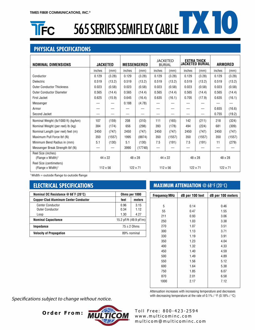
Nominal DC Resistance @ 68°F (20°C) Ohms/kft. (Ohms/ km)
Braid Coverage % Standard Premium Trishield Quadshield
Conductors 53 67 95 53 80 53 - 34
Center Conductor 48.2 (158) 48.2 (158) 48.2 (158) 48.2 (158) 48.2 (158) 48.2 (158)Outer Conductor 12.1 (40) 10.0 (33) 6.52 (21) 8.43 (28) 6.70 (22) 6.52 (21)Loop 60.3 (198) 58.2 (191) 54.7 (179) 56.6 (186) 54.9 (180) 54.7 (179)
Nominal Capacitance-all types 16.2 pF/ft (53.2 pF/m)
Impedance 75 ± 3 Ohms
Velocity of Propagation 85% nominal
PHYSICAL SPECIFICATIONS
59 SERIES DROP CABLE
ELECTRICAL SPECIFICATIONS
NOMINAL DIMENSIONS STANDARD PREMIUM TRISHIELD QUADSHIELDBraid Coverage % 53 and 67 95 53 and 80 53 - 34
inches (mm) inches (mm) inches (mm) inches (mm)
Conductor 0.0320 (0.81) 0.0320 (0.81) 0.0320 (0.81) 0.0320 (0.81) Dielectric 0.144 (3.66) 0.144 (3.66) 0.144 (3.66) 0.144 (3.66) Sealed APA Tape (1st Outer Conductor) 0.152 (3.86) 0.152 (3.86) 0.152 (3.86) 0.152 (3.86) Aluminum Braid (2nd Outer Conductor) 0.176 (4.47) 0.176 (4.47) 0.176 (4.47) 0.176 (4.47) Unsealed APA Tape (3rd Outer Conductor) — — — — 0.180 (4.57) 0.180 (4.57) Aluminum Braid (4th Outer Conductor) — — — — — — 0.205 (5.21) Jacket 0.240 (6.10) 0.240 (6.10) 0.244 (6.20) 0.265 (6.73)
Cable Width (Single)
Messenger Diameter (Single) 0.051 (1.30) 0.051 (1.30) 0.051 (1.30) 0.051 (1.30)Single Messengered Width 0.395 (10.0) 0.395 (10.0) 0.399 (10.1) 0.420 (10.7)Siamese Width 0.525 (13.3) 0.525 (13.3) — — 0.575 (14.6)Messenger Diameter (Siamese) 0.072 (1.83) — — — — 0.072 (1.83)Siamese Messengered Width 0.702 (17.8) — — — — 0.752 (19.1)
Messenger Break Strength Size Minimum Maximum
0.051 in (1.30mm) 185 lb (823 N) 245 lb (1090 N)0.072 in (1.83mm) 365 lb (1624 N) 490 lb (2180 N)
Cable Weight [lb./kft. (kg/km)]
Regular 53 and 67 95 53 80 53 - 34
Single 23 (34) 24 (36) 22 (33) 24 (36) 27 (40)Single Messengered 35 (52) 36 (54) 34 (51) 36 (54) 39 (58)Siamese 46 (68) 48 (71) — — — — 54 (80)Siamese Messengered 66 (98) — — — — — — 74 (110)
Underground
Single Flooded 22 (33) 24 (36) 23 (34) 24 (36) 26 (39)Siamese Flooded 45 (67) — — — — — — 52 (77)
lifeTime™
Single Flooded 22 (33) 24 (36) 23 (34) 24 (36) 26 (39)Single Flooded Messengered 34 (51) 36 (54) 35 (52) 36 (54) 38 (57)Siamese Flooded 45 (67) 47 (70) — — — — 51 (76)Siamese Flooded Messengered 65 (97) — — — — — — 72 (107)
Specifications subject to change without notice.
www .m u l t i c o m i n c . c omm u l t i c o m@mu l t i c o m i n c . c om
T o l l F r e e : 8 0 0 - 4 2 3 - 2 5 9 4O r d e r F r om :®

T10TIMES FIBER COMMUNICATIONS, INC.®
PART NUMBERS
6 SERIES DROP CABLE
BRAID COVERAGECONSTRUCTION STANDARD PREMIUM TRISHIELD QUADSHIELDNominal Braid Coverage % 60 90 60 80 60 - 40
PVC Jacket (Regular)
Single 02360 02560 02622 02627 02260T660-VB T690-VB T6T60-VB T6T80-VB T6Q-VB
Single (Colors) 02391 02591 02620 02625 02291T660-VC T690-VC T6T60-VC T6T80-VC T6Q-VC
Single Messengered 02364 02564 02623 02628 02264T660-VB-051M T690-VB-051M T6T60-VB-051M T6T80-VB-051M T6Q-VB-051M
Siamese 02396 — — — 02296T660SIAM-VB — — — T6QSIAM-VB
Siamese (Colors) 02356 — — — 02256T660SIAM-VC — — — T6QSIAM-VC
Siamese Messengered 02384 02584 — — 02284T660SIAM-VB-072M T690SIAM-VB-072M — — T6QSIAM-VB-072M
PVC Jacket (Underground Floodant)
Single Flooded 02386 02586 02624 02629 02286T660-FVB T690-FVB T6T60-FVB T6T80-FVB T6Q-FVB
Siamese Flooded 02353 02553 — — 02253T660SIAM-FVB T690SIAM-FVB — — T6QSIAM-FVB
Polyethylene Jacket (Underground Floodant)
Single Flooded 02321 02521 026H6 026K0 02221T660-FEB T690-FEB T6T60-FEB T6T80-FEB T6Q-FEB
PVC Jacket (lifeTime™ Floodant)
Single Flooded 32360 32560 32622 32627 32260T660-LTVB T690-LTVB T6T60-LTVB T6T80-LTVB T6Q-LTVB
Single Flooded Messengered 32364 32564 32623 32628 32264T660-LTVB-051M T690-LTVB-051M T6T60-LTVB-051M T6T80-LTVB-051M T6Q-LTVB-051M
Siamese Flooded 32396 — — — 32296T660SIAM-LTVB — — — T6QSIAM-LTVB
Siamese Flooded Messengered 32384 32584 — — 32284T660SIAM-LTVB-072M T690SIAM-LTVB-072M — — T6QSIAM-LTVB-072M
PVC Jacket , Flame Retardant – NEC Article 820 – “CATV ”***
Single 02360V 02560V 02622V 02627V 02260VT660-VBV T690-VBV T6T60-VBV T6T80-VBV T6Q-VBV
Single (Colors) 02391V 02591V 02620V 02625V 02291VT660-VCV T690-VCV T6T60-VCV T6T80-VCV T6Q-VCV
Siamese 02396V 02596V — — 02296VT660SIAM-VBV T690SIAM-VBV — — T6QSIAM-VBV
Siamese (Colors) 02356V — — — 02256VT660SIAM-VCV — — — T6QSIAM-VCV
PVC Jacket , Flame Retardant w/lifeTime™ – NEC Article 820 – “CATV ”***
Single Flooded 32360V 32560V 32622V 32627V 32260VT660-LTVBV T690-LTVBV T6T60-LTVBV T6T80-LTVBV T6Q-LTVBV
Single Flooded (Colors) 32391V 32591V 32620V 32625V 32291VT660-LTVCV T690-LTVCV T6T60-LTVCV T6T80-LTVCV T6Q-LTVCV
Siamese Flooded 32396V 32596V — — 32296VT660SIAM-LTVBV T690SIAM-LTVBV — — T6QSIAM-LTVBV
*** CSA - CMH: Change “V” to “F”CSA - CMG: Change “V” to “M”
UL CL2: Change “V” to “L”UL CM: Change “V” to “Y”
www .m u l t i c o m i n c . c omm u l t i c o m@mu l t i c o m i n c . c om
T o l l F r e e : 8 0 0 - 4 2 3 - 2 5 9 4O r d e r F r om :®
T10TIMES FIBER COMMUNICATIONS, INC.®
�������������� ! �!!"��#!$�%&�'�()*��+,
������*������+��*-��*���
03x3321x31dleihsirT & elgniS03x1421x61dleihsdauQ elgniS
Single Messengered 16x12 41x3063x6441x81esemaiS
Siamese Trishield & Quadshield 18x14 46x36Siamese Messengered 18x14 46x36Siamese Messengered Quadshield 22x14 56x36
���������� �� ���������� ��������������
5 0.57 1.8755 1.50 4.94
211 2.87 9.43250 3.12 10.22270 3.24 10.63300 3.43 11.25330 3.61 11.84350 3.72 12.20400 4.00 13.12450 4.28 14.04500 4.51 14.80550 4.76 15.62600 4.98 16.34750 5.62 18.44870 6.09 19.99
1000 6.54 21.46
Attenuation increases with increasing temperature and decreaseswith decreasing temperature at the rate of 0.1% /°F (0.18% / °C)
MAXIMUM ATTENUATION @ 68°F (20°C)
REEL SIZE
Flange
Width
6 SERIES DROP CABLEPART NUMBERS
BRAID COVERAGECONSTRUCTION STANDARD PREMIUM TRISHIELD QUADSHIELDNominal Braid Coverage % 60 90 60 80 60 - 40
PVC Jacket , Flame Retardant – NEC Article 820 – “CATVR ”***
Single 02360R — — — 02260RT660-VBR — — — T6Q-VBR
Single (Colors) — — — — 02291R— — — — T6Q-VCR
Siamese 02396R — — — —T660SIAM-VBR — — — —
PVC Jacket , Flame Retardant w/lifeTime™ – NEC Article 820 – “CATVR ”***
Single Flooded — — — — 32260R— — — — T6Q-LTVBR
Siamese Flooded 32396R — — — —T660SIAM-LTVBR — — — —
*** CSA - CMH: Change “V” to “F
CSA - CMG: Change “V” to “M”
UL - CL2: Change “V” to “L”
UL - CM: Change “V” to “Y”
Specifications subject to change without notice.
1 Width = outside flange to outside flange
www .m u l t i c o m i n c . c omm u l t i c o m@mu l t i c o m i n c . c om
T o l l F r e e : 8 0 0 - 4 2 3 - 2 5 9 4O r d e r F r om :®
T10TIMES FIBER COMMUNICATIONS, INC.®
Nominal DC Resistance @ 68°F (20°C) Ohms/kft. (Ohms/km)
Braid Coverage % Standard Premium Trishield Quadshield
Conductors 60 90 60 80 60 - 40
Center Conductor 30.4 (100) 30.4 (100) 30.4 (100) 30.4 (100) 30.4 (100)Outer Conductor 9.22 (30) 5.63 (18) 6.48 (21) 5.52 (18) 4.88 (16)Loop 39.6 (130) 36.0 (118) 36.9 (121) 35.9 (118) 35.3 (116)
Nominal Capacitance-all types 16.2 pF/ft (53.2 pF/m)
Impedance 75 ± 3 Ohms
Velocity of Propagation 85% nominal
PHYSICAL SPECIFICATIONS
6 SERIES DROP CABLE
ELECTRICAL SPECIFICATIONS
�����."/��!������ ��.�/.�/ �!���� ������!"/ 0�./���!"/��&*��12��&'�3 04 - 0608 dna 060906
inches (mm) inches (mm) inches (mm) inches (mm)
)20.1(3040.0)20.1(3040.0)20.1(3040.0)20.1(3040.0rotcudnoC)75.4(081.0)75.4(081.0)75.4(081.0)75.4(081.0cirtceleiD
Sealed APA Tape (1st Outer Conductor) 0.188 (4.78) 0.188 (4.78) 0.188 (4.78) 0.188 (4.78)Aluminum Braid (2nd Outer Conductor) 0.212 (5.38) 0.212 (5.38) 0.212 (5.38) 0.212 (5.38)Unsealed APA Tape (3rd Outer Conductor) — — — — 0.216 (5.49) 0.216 (5.49)Aluminum Braid (4th Outer Conductor) — — — — — — 0.241 (6.12)
)45.7(792.0)60.7(872.0)39.6(372.0)39.6(372.0tekcaJ
�&4%�)*��+$�*�'%�,
)03.1(150.0)03.1(150.0)03.1(150.0)03.1(150.0)elgniS( retemaiD regnesseM)5.11(254.0)0.11(334.0)9.01(824.0)9.01(824.0htdiW deregnesseM elgniS)2.61(936.0——)0.51(195.0)0.51(195.0htdiW esemaiS)38.1(270.0————)38.1(270.0)esemaiS( retemaiD regnesseM)7.02(618.0————)5.91(867.0htdiW deregnesseM esemaiS
���*(&����*�*�� *�+�'�����5&�����'������
0.051 in (1.30 mm) 185 lb (823 N) 245 lb (1090 N)0.072 in (1.83 mm) 365 lb (1624 N) 490 lb (2180 N)
�&4%�)�*'+�6%4785��7$5'85�,9
��'�%&� 04 - 0608060906
)94(33)34(92)24(82)34(92)24(82elgniS)76(54)16(14)06(04)16(14)06(04deregnesseM elgniS)89(66——————)58(75esemaiS)821(68——————)511(77deregnesseM esemaiS
�����'�1���
)64(13)54(03)34(92)34(92)04(72dedoolF elgniS)49(36————)68(85)28(55dedoolF esemaiS
lifeTime™
)64(13)54(03)34(92)34(92)04(72dedoolF elgniS)46(34)36(24)16(14)06(04)85(93deregnesseM dedoolF elgniS)49(36—————)28(55dedoolF esemaiS)121(18——————)211(57deregnesseM dedoolF esemaiS
Specifications subject to change without notice.
www .m u l t i c o m i n c . c omm u l t i c o m@mu l t i c o m i n c . c om
T o l l F r e e : 8 0 0 - 4 2 3 - 2 5 9 4O r d e r F r om :®

T10TIMES FIBER COMMUNICATIONS, INC.®
PART NUMBERS
11 SERIES DROP CABLE
*** CSA - CMH: Change “V” to “F”
CSA - CMG: Change “V” to “M”
UL CL2: Change “V” to “L”
UL CM: Change “V” to “Y”
BRAID COVERAGECONSTRUCTION STANDARD PREMIUM TRISHIELD QUADSHIELD QUADSHIELDNominal Braid Coverage % 53 60 60 53 - 32 60 - 40
PVC Jacket (Regular)
Single 02362 023T2 02642 02262 022T2T1153-VB T1160-VB T11T60-VB T11Q53/32-VB T11Q-VB
Single (Colors) 02390 023U2 02640 — —T1153-VC T1160-VC T11T60-VC — —
Single Messengered (Pole-to-House) 02369 023V2 02643 02269 —T1153-VB-083M T1160-VB-083M T11T60-VB-083M T11Q53/32 —
-VB-083M
Single Messengered (Pole-to-Pole) — 023VD — — 022V7— T1160-VB-109M — — T11Q-VB-109M
PVC Jacket (Underground Floodant)
Single Flooded 02382 023W2 02644 02282 —T1153-FVB T1160-FVB T11T60-FVB T11Q53/32-FVB —
Single Flooded (colors) 02398 023W1 026W1 02298 —T1153-FVC T1160-FVC T11T60-FVC T11Q53/32-FVC —
Polyethylene JacketSingle Flooded 02381 023W4 026W4 02281 022W4
T1153-FEB T1160-FEB T11T60-FEB T11Q53/32-FEB T11Q-FEB
Single Flooded (Colors) 02135 023WA 026WA 02297 022WAT1153-FEC T1160-FEC T11T60-FEC T11Q53/32-FEC T11Q-FEC
Single Messengered (Pole-to-House) 02324 — — — —T1153-EB-083M — — — —
Single Messengered (Pole-to-Pole) 02366 023VE — 02266 —T1153-EB-109M T1160-EB-109M — T11Q53/32-EB —
-109M
PVC Jacket (lifeTime™ Floodant)Single Flooded 32362 323T2 32642 32262 322T2
T1153-LTVB T1160-LTVB T11T60-LTVB T11Q53/32-LTVB T11Q-LTVB
Single Flooded Messengered (Pole-to-House) 32369 323V2 32643 32269 322T1T1153-LTVB-083M T1160-LTVB T11T60-LTVB T11Q53/32-LTVB T11Q-LTVB
-083M -083M -083M -083M
Single Flooded Messengered (Pole-to-Pole)* — — — — 322V7— — — — T11Q-LTVB-109M
PVC Jacket, Flame Retardant – NEC Article 820 – “CATV ”***Single 02362V 023T2V 02642V 02262V —
T1153-VBV T1160-VBV T11T60-VBV T11Q53/32-VBV —
Single (Colors) — — — 02267V —— — — T11Q53/32-VCV —
PVC Jacket, Flame Retardant w/lifeTime™ – NEC Article 820 – “CATV ”***Single 32362V — — 32262V 322T2V
T1153-LTVBV — — T11Q53/32-LTVBV T11Q-LTVBV
Single (Colors) — — — — —
PVC Jacket, Flame Retardant – NEC Article 820 – “CATVR ”***Single — 023T2R — — 022T2R
— T1160-VBR — — T11Q-VBR
PVC Jacket, Flame Retardant w/lifeTime™ – NEC Article 820 – “CATVR ”***Single — 323T2R — — 322T2R
— T1160-LTVBR — — T11Q-LTVBR
www .m u l t i c o m i n c . c omm u l t i c o m@mu l t i c o m i n c . c om
T o l l F r e e : 8 0 0 - 4 2 3 - 2 5 9 4O r d e r F r om :®

T10TIMES FIBER COMMUNICATIONS, INC.®
CONSTRUCTION TYPE REEL SIZE(Flange x Width)
Series 11 inches centimeters
Single 18x14 46x36Single Trishield 18x14 46x36Single Quadshield 18x14 46x36Single Messengered 22x14 56x36Single Messengered Trishield 22x14 56x36Single Messengered Quadshield 22x14 56x36
Frequency MHz dB per 100 feet dB per 100 meters
5 0.36 1.1855 0.95 3.12
211 1.81 5.95250 1.98 6.50270 2.06 6.76300 2.17 7.12330 2.29 7.51350 2.36 7.74400 2.53 8.30450 2.69 8.83500 2.85 9.35550 3.01 9.88600 3.16 10.37750 3.58 11.75870 3.90 12.80
1000 4.23 13.88
Attenuation increases with increasing temperature and decreaseswith decreasing temperature at the rate of 0.1% / °F (0.18% / °C)
REEL SIZE
MAXIMUM ATTENUATION @ 68°F (20°C)
Flange
Width
11 SERIES DROP CABLE
Specifications subject to change without notice.
1 Width = outside flange to outside flange
www .m u l t i c o m i n c . c omm u l t i c o m@mu l t i c o m i n c . c om
T o l l F r e e : 8 0 0 - 4 2 3 - 2 5 9 4O r d e r F r om :®

T10TIMES FIBER COMMUNICATIONS, INC.®
Nominal DC Resistance @ 68°F (20°C) Ohms/kft. (Ohms/km)
Braid Coverage % Standard Premium Trishield Quadshield Quadshield
Conductors 53 60 60 53 - 32 60 - 40
Center Conductor 12.1 (40) 12.1 (40) 12.1 (40) 12.1 (40) 12.1 (40)Outer Conductor 7.22 (24) 6.48 (21) 4.55 (15) 3.99 (13) 3.55 (12)Loop 19.3 (64) 18.6 (61) 16.7 (55) 16.1 (53) 15.7 (52)
Nominal Capacitance-all types 16.2 pF/ft (53.2 pF/m)
Impedance 75 ± 3 Ohms
Velocity of Propagation 85% nominal
PHYSICAL SPECIFICATIONSELECTRICAL SPECIFICATIONS
PHYSICAL SPECIFICATIONS
11 SERIES DROP CABLE
/"!���/.�0/"!���/.�0/"!����������!� /�./�.��������!��/".�������&*��12��&'�3 53 60 60 53 - 32 60 - 40
inches (mm) inches (mm) inches (mm) inches (mm) inches (mm)
)36.1(1460.0)36.1(1460.0)36.1(1460.0)36.1(1460.0)36.1(1460.0rotcudnoC)11.7(082.0)11.7(082.0)11.7(082.0)11.7(082.0)11.7(082.0cirtceleiD
Sealed APA Tape (1st Outer Conductor) 0.288 (7.32) 0.288 (7.32) 0.288 (7.32) 0.288 (7.32) 0.288 (7.32)Aluminum Braid (2nd Outer Conductor) 0.312 (7.92) 0.312 (7.92) 0.312 (7.92) 0.312 (7.92) 0.312 (7.92)Unsealed APA Tape (3rd Outer Conductor) — — — — 0.316 (8.03) 0.316 (8.03) 0.316 (8.03)Aluminum Braid (4th Outer Conductor) — — — — — — 0.341 (8.66) 0.341 (8.66)
)3.01(704.0)3.01(704.0)2.01(004.0)2.01(004.0)2.01(004.0tekcaJ
�&4%�)*��+
Messenger Diameter (Pole-to-House) 0.083 (2.11) 0.083 (2.11) 0.083 (2.11) 0.083 (2.11) 0.083 (2.11))77.2(901.0)77.2(901.0)77.2(901.0)77.2(901.0)77.2(901.0)eloP-ot-eloP( retemaiD regnesseM)6.51(516.0)6.51(516.0)4.51(806.0)4.51(806.0)4.51(806.0)esuoH-ot-eloP( deregnesseM elgniS)0.61(136.0)0.61(136.0)9.51(426.0)9.51(426.0)9.51(426.0*)eloP-ot-eloP( deregnesseM elgniS
���*(&����*�*�� *�+�'�����5&�����'������
0.083 in (2.11 mm) 460 lb (2046 N) 622 lb (2767 N)
0.109 in (2.77 mm) 1800 lb (8007 N) 2190 lb (9742 N)
�&4%�)�*'+�6%4785��7$5'85�,9 :�;&�5����'�%&�
)68(85)68(85)38(65)68(85)68(85elgniS——)421(38)521(48)821(68)821(68)esuoH-ot-eloP( deregnesseM elgniS ——————)941(001——)eloP-ot-eloP( deregnesseM elgniS
1%��+%���;&�5����'�%&�
——————)17(84——elgniS————————)701(27)esuoH-ot-eloP( deregnesseM elgniS
)941(001)921(78——)821(68)821(68)eloP-ot-eloP( deregnesseM elgniS
�����'�1���
——)38(65)68(85)58(75)58(75)CVP( dedoolF elgniS )37(94)17(84)37(94)17(84)07(74)EP( dedoolF elgniS
lifeTime™
)58(75)38(65)68(85)58(75)58(75dedoolF elgniSSingle Flooded Messengered (Pole-to-House) 82 (122) 83 (124) 83 (124) 81 (121) 82 (122)
Single Flooded Messengered (Pole-to-Pole) — — — — — — 98 (146) — —
Specifications subject to change without notice.
www .m u l t i c o m i n c . c omm u l t i c o m@mu l t i c o m i n c . c om
T o l l F r e e : 8 0 0 - 4 2 3 - 2 5 9 4O r d e r F r om :®

T10TIMES FIBER COMMUNICATIONS, INC.®
5 0.77 2.53 0.57 1.87 0.56 1.84 0.36 1.18
55 1.88 6.18 1.50 4.94 1.22 4.00 0.95 3.12
211 3.59 11.79 2.87 9.43 2.29 7.53 1.81 5.95
250 3.89 12.77 3.12 10.22 2.49 8.17 1.98 6.50
270 4.05 13.29 3.24 10.63 2.59 8.50 2.06 6.76
300 4.27 14.01 3.43 11.25 2.74 8.99 2.17 7.12
330 4.50 14.76 3.61 11.84 2.89 9.47 2.29 7.51
350 4.64 15.22 3.72 12.20 2.98 9.78 2.36 7.74
400 4.88 16.01 4.00 13.12 3.20 10.50 2.53 8.30
450 5.30 17.39 4.28 14.04 3.41 11.19 2.69 8.83
500 5.50 18.04 4.51 14.80 3.61 11.84 2.85 9.35
550 5.90 19.36 4.76 15.62 3.80 12.47 3.01 9.88
600 6.18 20.28 4.98 16.34 3.99 13.09 3.16 10.37
750 6.96 22.83 5.62 18.44 4.50 14.76 3.58 11.75
870 7.54 24.75 6.09 19.99 4.87 15.99 3.90 12.80
1000 8.09 26.54 6.54 21.46 5.25 17.22 4.23 13.88
Attenuation increases with increasing temperature and decreases with decreasing temperature at the rate of 0.1% / °F (0.18% / °C)
11 SeriesdB/100 feet dB/100 meters
59 SeriesMHZ dB/100 feet dB/100 meters
6 SeriesdB/100 feet dB/100 meters
7 SeriesdB/100 feet dB/100 meters
Frequency
DROP CABLE ATTENUATIONATTENUATION SUMMARY (maximum) @ 68°F (20°C)
Specifications subject to change without notice.
www .m u l t i c o m i n c . c omm u l t i c o m@mu l t i c o m i n c . c om
T o l l F r e e : 8 0 0 - 4 2 3 - 2 5 9 4O r d e r F r om :®

T10TIMES FIBER COMMUNICATIONS, INC.®
T10 or TX10 1 21- Cable Series 2- Jacket Configuration 2- Jacket Configuration
412 - 0.412" Cable Series “ “ - Unjacketed
500 - 0.500" Cable Series VI - Unjacketed, Tracer Coded
565 - 0.565" Cable Series J - Jacketed
625 - 0.625" Cable Series JX - Jacketed, Extra Thick Jacket
700 - 0.703" Cable Series JXVI - Jacketed, Extra Thick Jacket, Tracer Coded
750 - 0.750" Cable Series JVI - Jacketed, Tracer Coded
840 - 0.840" Cable Series MS - Jacketed, Messengered
875 - 0.875" Cable Series JB - Jacketed, Flooded - Underground
1000 - 1.000" Cable Series JBX - Jacketed, Flooded - Underground, Extra Thick
Jacket
1160 - 1.160" Cable Series JBXVI - Jacketed, Flooded - Underground, Extra Thick
Jacket, Tracer Coded
JBVI - Jacketed, Flooded - Underground, Tracer
Coded
JBF - Jacketed, Flooded - Aerial*
JBFVI - Jacketed, Flooded - Aerial*, Tracer Coded
JBA - Jacketed, Armored
JBAVI - Jacketed, Armored, Tracer Coded
V - NEC - Article 820, CATV (UL) Listed,
Unjacketed
SC - Solid Copper Inner Conductor
Example: MI 24714 Part Number T10750JBFVI T10 750 JBF VI
TFC T10 Tracer Coded0.750" Cable Series Jacketed, Flooded, Aerial*
MI 25502 Part Number TX10565JB TX10 565 JB
TFC TX100.565" Cable Series Jacketed, Flooded, Underground
* Aerial Non-dripping flooding compound
SEMIFLEX CABLE DESCRIPTION LEGEND
www .m u l t i c o m i n c . c omm u l t i c o m@mu l t i c o m i n c . c om
T o l l F r e e : 8 0 0 - 4 2 3 - 2 5 9 4O r d e r F r om :®
TIMES FIBER COMMUNICATIONS, INC.®
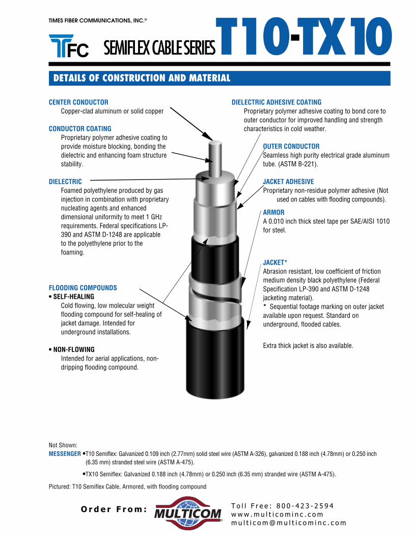
T10CENTER CONDUCTOR
Copper-clad aluminum or solid copper
CONDUCTOR COATINGProprietary polymer adhesive coating toprovide moisture blocking, bonding thedielectric and enhancing foam structurestability.
DIELECTRICFoamed polyethylene produced by gasinjection in combination with proprietarynucleating agents and enhanceddimensional uniformity to meet 1 GHzrequirements. Federal specifications LP-390 and ASTM D-1248 are applicableto the polyethylene prior to thefoaming.
Not Shown:MESSENGER •T10 Semiflex: Galvanized 0.109 inch (2.77mm) solid steel wire (ASTM A-326), galvanized 0.188 inch (4.78mm) or 0.250 inch
(6.35 mm) stranded steel wire (ASTM A-475).
•TX10 Semiflex: Galvanized 0.188 inch (4.78mm) or 0.250 inch (6.35 mm) stranded wire (ASTM A-475).
Pictured: T10 Semiflex Cable, Armored, with flooding compound
JACKET*Abrasion resistant, low coefficient of frictionmedium density black polyethylene (FederalSpecification LP-390 and ASTM D-1248jacketing material).* Sequential footage marking on outer jacketavailable upon request. Standard onunderground, flooded cables.
FLOODING COMPOUNDS• SELF-HEALING
Cold flowing, low molecular weightflooding compound for self-healing ofjacket damage. Intended forunderground installations.
• NON-FLOWINGIntended for aerial applications, non-dripping flooding compound.
SEMIFLEX CABLE SERIES
Extra thick jacket is also available.
ARMORA 0.010 inch thick steel tape per SAE/AISI 1010for steel.
DIELECTRIC ADHESIVE COATINGProprietary polymer adhesive coating to bond core toouter conductor for improved handling and strengthcharacteristics in cold weather.
OUTER CONDUCTORSeamless high purity electrical grade aluminumtube. (ASTM B-221).
JACKET ADHESIVEProprietary non-residue polymer adhesive (Not
used on cables with flooding compounds).
DETAILS OF CONSTRUCTION AND MATERIAL
-T10 TX10
www .m u l t i c o m i n c . c omm u l t i c o m@mu l t i c o m i n c . c om
T o l l F r e e : 8 0 0 - 4 2 3 - 2 5 9 4O r d e r F r om :®

T10TIMES FIBER COMMUNICATIONS, INC.®
FEATURES AND BENEFITS
The T10 and TX10 Semiflex Cable Series offer a number of product features which enhance product performance andsystem operation.
BEND RADIUSBoth T10 and TX10 cables exhibit reduced bendradii to easily accommodate vault and pedestalplacement. Refer to cable series data sheets forminimum bend radius specification.
BONDINGThe bonded construction of semiflex cablebegins at the center conductor to dielectricinterface. Bonding serves as corrosionprotection resulting from moisture ingress andfacilitates stripping of the dielectric withoutleaving a harmful residue. Continuing from thedielectric to the outer conductor, controlledbonding provides adhesion strength to -40˚ C,drastically reducing center conductor pull-outsdue to extreme temperature changes. Inaddition, bonding improves handling andfacilitates the use of standard connectors.Further bonding of the outer conductor to jacketprevents concealment of aluminum sheathdamage, identifying problems before the cable isinstalled.
T10 and TX10 semiflex cables’ unique bondedconstruction allows all components to operatetogether as a single unit. A fully bondedcomposite construction offers the benefits ofincreased pull strength and resistance topossible sidewall pressure damage duringinstallation. Triple bonding also solves theinstances of connector pull-outs, furtherreducing cable service problems after installaton.
FLOODING COMPOUNDFlooding compounds come in a cold flowing, self-healing form for underground installations and anon-dripping aerial application form. Floodingcompounds are used as an additional layer ofcorrosion protection.
Where greater protection is required, Times offersan armored construction. A flooded steel tape andjacket are layered over the standard floodedjacketed cable, increasing mechanical strengthnecessary for rodent protection and rocky soil.
1 GHz BANDWIDTHT10 and TX10 are the only cables which arespecified to consistently sweep to 1 GHz.Specifying 1 GHz bandwidth for rebuilds,upgrades or new plant allows a system to handlefuture increasing capacity needs demanded bymore channels, higher definition television andother emerging technologies.
SEMIFLEX CABLE SERIES-T10 TX10
www .m u l t i c o m i n c . c omm u l t i c o m@mu l t i c o m i n c . c om
T o l l F r e e : 8 0 0 - 4 2 3 - 2 5 9 4O r d e r F r om :®

TIMES FIBER COMMUNICATIONS, INC.®
T10
Application: Where cable is exposed to extensive mechanical abuseand rodent attack, armored semiflex cable is recommended. Used fordirect burial applications, Armored semiflex cable features a floodedsteel tape and jacket which are layered over the standard floodedjacketed cable to increase mechanical strength.
ARMORED
JACKETED BURIAL
Application: Jacketed Burial semiflex cable is recommended forunderground applications in conduit or direct burial installations.This version features a cold flowing, self-healing flooding compoundfor underground applications, providing an additional layer ofcorrosion protection. For aerial applications, non-dripping floodingcompound is used which also serves as an additional layer ofcorrosion protection.
MESSENGEREDApplication: Messengered semiflex cable is recommended for aerialfeeder installations where strand installation is not practical. T10412and T10500 semiflex cable is designed with a strong, integral,galvanized solid steel wire which supports the cable in aerialinstallations. TX10625 and TX10565 semiflex cable features ajacketed galvanized stranded steel wire which also acts as a support,relieving the cable from undue tension. Resting ladders onmessengered cable is not recommended.
Application: Recommended for aerial installations in a non-corrosiveenvironment, unjacketed semiflex cable features bonding of thecenter conductor to the dielectric and dielectric to the outerconductor. This bonding prevents moisture ingress and facilitatesconnectorization since it leaves no harmful residue.
UNJACKETED
JACKETEDApplication: For aerial applications in urban and coastalenvironments, Jacketed semiflex cable is recommended wherehighly corrosive conditions may exist. This cable features a triplebonding of the center conductor to the dielectric, dielectric to theouter conductor and outer conductor to the jacket and is designedto withstand more abrasion and mechanical abuse than anunjacketed version. With an extra thick jacket, this cable willwithstand more abrasion and mechanical abuse than the standardjacketed burial cable.
SEMIFLEX CABLE SERIES -T10 TX10
www .m u l t i c o m i n c . c omm u l t i c o m@mu l t i c o m i n c . c om
T o l l F r e e : 8 0 0 - 4 2 3 - 2 5 9 4O r d e r F r om :®
T10TIMES FIBER COMMUNICATIONS, INC.®
CONSTRUCTION
CENTER CONDUCTORCopper-Clad Aluminum
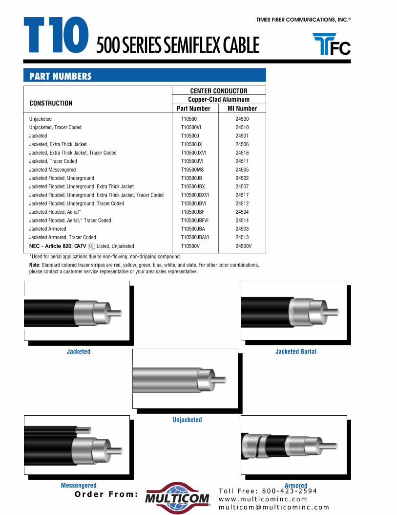
Part Number MI NumberUnjacketed T10500 24500
Unjacketed, Tracer Coded T10500VI 24510
Jacketed T10500J 24501
Jacketed, Extra Thick Jacket T10500JX 24506
Jacketed, Extra Thick Jacket, Tracer Coded T10500JXVI 24516
Jacketed, Tracer Coded T10500JVI 24511
Jacketed Messengered T10500MS 24505
Jacketed Flooded, Underground T10500JB 24502
Jacketed Flooded, Underground, Extra Thick Jacket T10500JBX 24507
Jacketed Flooded, Underground, Extra Thick Jacket, Tracer Coded T10500JBXVI 24517
Jacketed Flooded, Underground, Tracer Coded T10500JBVI 24512
Jacketed Flooded, Aerial* T10500JBF 24504
Jacketed Flooded, Aerial,* Tracer Coded T10500JBFVI 24514
Jacketed Armored T10500JBA 24503
Jacketed Armored, Tracer Coded T10500JBAVI 24513
NEC - Article 820, CATV Listed, Unjacketed T10500V 24500V
*Used for aerial applications due to non-flowing, non-dripping compound.
Note: Standard colored tracer stripes are red, yellow, green, blue, white, and slate. For other color combinations,please contact a customer service representative or your area sales representative.
PART NUMBERS
500 SERIES SEMIFLEX CABLE
Jacketed Jacketed Burial
Unjacketed
Messengered Armored
www .m u l t i c o m i n c . c omm u l t i c o m@mu l t i c o m i n c . c om
T o l l F r e e : 8 0 0 - 4 2 3 - 2 5 9 4O r d e r F r om :®

TIMES FIBER COMMUNICATIONS, INC.®
T10inches (mm) inches (mm) inches (mm) inches (mm) inches (mm) inches (mm) inches (mm)
Conductor 0.109 (2.77) 0.109 (2.77) 0.109 (2.77) 0.109 (2.77) 0.109 (2.77) 0.109 (2.77) 0.109 (2.77)
Dielectric 0.450 (11.4) 0.450 (11.4) 0.450 (11.4) 0.450 (11.4) 0.450 (11.4) 0.450 (11.4) 0.450 (11.4)
Outer Conductor Thickness 0.025 (0.64) 0.025 (0.64) 0.025 (0.64) 0.025 (0.64) 0.025 (0.64) 0.025 (0.64) 0.025 (0.64)
Outer Conductor Diameter 0.500 (12.7) 0.500 (12.7) 0.500 (12.7) 0.500 (12.7) 0.500 (12.7) 0.500 (12.7) 0.500 (12.7)
First Jacket — — 0.560 (14.2) 0.630 (16.0) 0.580 (14.7) 0.570 (14.5) 0.640 (16.3) 0.570 (14.5)
Messenger — — — — — — 0.109 (2.77) — — — — — —
Armor .— — — — — — — — — — — — 0.590 (15.0)
Second Jacket .— — — — — — — — — — — — 0.690 (17.5)
Nominal Weight (lb/1000 ft) (kg/km) 78 (116) 99 (147) 126 (188) 154 (229) 103 (153) 130 (193) 199 (296)
Nominal Weight (per reel) lb (kg) 269 (122) 319 (145) 409 (186) 479 (217) 328 (149) 419 (190) 588 (267)
Nominal Length (per reel) feet (m) 2450 (747) 2450 (747) 2450 (747) 2450 (747) 2450 (747) 2450 (747) 2450 (747)
Maximum Pull Force lbf (N) 300 (1334) 300 (1334) 300 (1334) 900 (4003) 300 (1334) 300 (1334) 300 (1334)
Minimum Bend Radius in (mm) 4.0 (102) 3.5 (89) 3.5 (89) 4.0 (102) 4.0 (102) 4.0 (102) 9.7 (246)
Messenger Break Strength lbf (N) — — — — — — 1800 (8007) — — — — — —
Reel Size (inches)(Flange x Width)1 36 x 22 36 x 22 42 x 22 42 x 22 36 x 22 42 x 22 42 x 22
Reel Size (centimeters)(Flange x Width)1 91 x 56 91 x 56 107 x 56 107 x 56 91 x 56 107 x 56 107 x 56
* All T10 Unjacketed Cable is available rated per NEC Article 820 - CATV .1 Width = outside flange to outside flange
JACKETED ARMOREDEXTRA THICK
JACKETJACKETED
BURIALEXTRA THICK
JACKETED BURIALMESSENGEREDUNJACKETED*
PHYSICAL SPECIFICATIONS
500 SERIES SEMIFLEX CABLE
NOMINAL DIMENSIONS
Frequency MHz dB per 100 feet dB per 100 meters
5 0.16 0.5255 0.55 1.80
211 1.08 3.55250 1.19 3.92270 1.24 4.07300 1.31 4.30330 1.38 4.54350 1.43 4.69400 1.53 5.02450 1.63 5.35500 1.73 5.68550 1.82 5.97600 1.91 6.27750 2.16 7.09870 2.35 7.69
1000 2.53 8.30
Attenuation increases with increasing temperature and decreaseswith decreasing temperature at the rate of 0.1% / °F (0.18% / °C)
MAXIMUM ATTENUATION @ 68°F (20°C)
Nominal DC Resistance @ 68˚F (20°C) Ohms per 1000
Copper-Clad Aluminum Center Conductor feet meters
Center Conductor 1.34 4.40 Outer Conductor 0.36 1.18
Loop 1.70 5.58
Nominal Capacitance 15.6 pF/ft (51.2 pF/m)
Impedance 75 ± 2 Ohms
Velocity of Propagation 87% nominal
ELECTRICAL SPECIFICATIONS
Specifications subject to change without notice.
www .m u l t i c o m i n c . c omm u l t i c o m@mu l t i c o m i n c . c om
T o l l F r e e : 8 0 0 - 4 2 3 - 2 5 9 4O r d e r F r om :®

T10TIMES FIBER COMMUNICATIONS, INC. ®
CONSTRUCTION
CENTER CONDUCTORCopper-Clad Aluminum
Part Number MI Number0064252601TdetekcajnU
01642IV52601TdedoC recarT ,detekcajnU
10642J52601TdetekcaJ
60642XJ52601TtekcaJ kcihT artxE ,detekcaJ
61642IVXJ52601TdedoC recarT ,tekcaJ kcihT artxE ,detekcaJ
11642IVJ52601TdedoC recarT ,detekcaJ
50642SM52601TderegnesseM detekcaJ
20642BJ52601TdnuorgrednU ,dedoolF detekcaJ
Jacketed Flooded, Underground, Extra Thick Jacket T10625JBX 24607
Jacketed Flooded, Underground, Extra Thick Jacket, Tracer Coded T10625JBXVI 24617
21642IVBJ52601TdedoC recarT ,dnuorgrednU ,dedoolF detekcaJ
40642FBJ52601T*laireA ,dedoolF detekcaJ
41642IVFBJ52601TdedoC recarT*,laireA ,dedoolF detekcaJ
30642ABJ52601TderomrA detekcaJ
31642IVABJ52601TdedoC recarT ,deromrA detekcaJ
NEC - Article 820, CATV V00642V52601TdetekcajnU ,detsiL
*Used for aerial applications due to non-flowing, non-dripping compound.
Note: Standard colored tracer stripes are red, yellow, green, blue, white, and slate. For other color combinations,please contact a customer service representative or your area sales representative.
PART NUMBERS
625 SERIES SEMIFLEX CABLE
lairuB detekcaJdetekcaJ
Unjacketed
Messengered Armored
www .m u l t i c o m i n c . c omm u l t i c o m@mu l t i c o m i n c . c om
T o l l F r e e : 8 0 0 - 4 2 3 - 2 5 9 4O r d e r F r om :®

TIMES FIBER COMMUNICATIONS, INC.®
T10inches (mm) inches (mm) inches (mm) inches (mm) inches (mm) inches (mm) inches (mm)
Conductor 0.136 (3.45) 0.136 (3.45) 0.136 (3.45) 0.136 (3.45) 0.136 (3.45) 0.136 (3.45) 0.136 (3.45)
Dielectric 0.563 (14.3) 0.563 (14.3) 0.563 (14.3) 0.563 (14.3) 0.563 (14.3) 0.563 (14.3) 0.563 (14.3)
Outer Conductor Thickness 0.031 (0.79) 0.031 (0.79) 0.031 (0.79) 0.031 (0.79) 0.031 (0.79) 0.031 (0.79) 0.031 (0.79)
Outer Conductor Diameter 0.625 (15.9) 0.625 (15.9) 0.625 (15.9) 0.625 (15.9) 0.625 (15.9) 0.625 (15.9) 0.625 (15.9)
First Jacket — — 0.685 (17.4) 0.755 (19.2) 0.705 (17.9) 0.695 (17.7) 0.765 (19.4) 0.695 (17.7)
Messenger — — — — — — 0.188 (4.78) — — — — — —
Armor .— — — — — — — — — — — — 0.715 (18.2)
Second Jacket .— — — — — — — — — — — — 0.815 (20.7)
Nominal Weight (lb/1000 ft) (kg/km) 122 (182) 147 (219) 180 (268) 249 (371) 151 (225) 185 (275) 268 (399)
Nominal Weight (per reel) lb (kg) 399 (181) 461 (209) 587 (266) 758 (344) 472 (214) 599 (272) 803 (364)
Nominal Length (per reel) feet (m) 2450 (747) 2450 (747) 2450 (747) 2450 (747) 2450 (747) 2450 (747) 2450 (747)
Maximum Pull Force lbf (N) 475 (2113) 475 (2113) 475 (2113) 1995 (8874) 475 (2113) 475 (2113) 475 (2113)
Minimum Bend Radius in (mm) 5.0 (127) 4.5 (114) 4.5 (114) 5.0 (127) 5.0 (127) 5.0 (127) 11.4 (290)
Messenger Break Strength lbf (N) — — — — — — 3990 (17748) — — — — — —
Reel Size (inches)
(Flange x Width)1 42 x 22 42 x 22 48 x 28 50 x 28 42 x 22 48 x 28 48 x 28Reel Size (cm)
(Flange x Width)1 107 x 56 107 x 56 122 x 71 127 x 71 107 x 56 122 x 71 122 x 71
* All T10 Unjacketed Cable is available rated per NEC Article 820 - CATV 1 Width = outside flange to outside flange
JACKETED ARMOREDEXTRA THICK
JACKETJACKETED
BURIALEXTRA THICK
JACKETED BURIALMESSENGEREDUNJACKETED*NOMINAL DIMENSIONS
PHYSICAL SPECIFICATIONS
625 SERIES SEMIFLEX CABLE
ATTENUATION @ 68°F (20°C)
Frequency MHz dB per 100 feet dB per 100 meters
5 0.13 0.4355 0.45 1.46
211 0.89 2.92250 0.98 3.22270 1.02 3.35300 1.08 3.54330 1.14 3.75350 1.18 3.87400 1.27 4.17450 1.35 4.43500 1.43 4.69550 1.51 4.95600 1.58 5.18750 1.79 5.87870 1.95 6.401000 2.11 6.92
Attenuation increases with increasing temperature and decreaseswith decreasing temperature at the rate of 0.1% / °F (0.18% / °C)
MAXIMUM ATTENUATION @ 68°F (20°C)
Nominal DC Resistance @ 68˚F (20°C) Ohms per 1000
Copper-Clad Aluminum Center Conductor feet meters
Center Conductor 0.86 2.82 Outer Conductor 0.23 0.75
Loop 1.09 3.58
Nominal Capacitance 15.6 pF/ft (51.2 pF/m)
Impedance 75 ± 2 Ohms
Velocity of Propagation 87% nominal
ELECTRICAL SPECIFICATIONS
Specifications subject to change without notice.
www .m u l t i c o m i n c . c omm u l t i c o m@mu l t i c o m i n c . c om
T o l l F r e e : 8 0 0 - 4 2 3 - 2 5 9 4O r d e r F r om :®

T10TIMES FIBER COMMUNICATIONS, INC. ®
CONSTRUCTION
CENTER CONDUCTORCopper-Clad Aluminum
Part Number MI Number0074205701TdetekcajnU
01742IV05701TdedoC recarT ,detekcajnU
10742J05701TdetekcaJ
60742XJ05701TtekcaJ kcihT atxE ,detekcaJ
61742IVXJ05701TdedoC recarT ,tekcaJ kcihT artxE ,detekcaJ
11742IVJ05701TdedoC recarT ,detekcaJ
50742SM05701TderegnesseM detekcaJ
20742BJ05701TdnuorgrednU ,dedoolF detekcaJ
Jacketed Flooded, Underground, Extra Thick Jacket T10750JBX 24707
Jacketed Flooded, Underground, Extra Thick Jacket, Tracer Coded T10750JBXVI 24717
21742IVBJ05701TdedoC recarT ,dnuorgrednU ,dedoolF detekcaJ
40742FBJ05701T*laireA ,dedoolF detekcaJ
41742IVFBJ05701TdedoC recarT *,laireA ,dedoolF detekcaJ
30742ABJ05701TderomrA detekcaJ
31742IVABJ05701TdedoC recarT ,deromrA detekcaJ
NEC - Article 820, CATV Listed, Unjacketed T10750V 24700V
*Used for aerial applications due to non-flowing, non-dripping compound.
Note: Standard colored tracer stripes are red, yellow, green, blue, white, and slate. For other color combinations, pleasecontact a customer service representative or your area sales representative.
PART NUMBERS
750 SERIES SEMIFLEX CABLE
lairuB detekcaJdetekcaJ
Unjacketed
Messengered Armored
www .m u l t i c o m i n c . c omm u l t i c o m@mu l t i c o m i n c . c om
T o l l F r e e : 8 0 0 - 4 2 3 - 2 5 9 4O r d e r F r om :®

TIMES FIBER COMMUNICATIONS, INC.®
T10750 SERIES SEMIFLEX CABLE
Frequency MHz dB per 100 feet dB per 100 meters
5 0.11 0.3655 0.37 1.21
211 0.73 2.41250 0.81 2.65270 0.84 2.76300 0.89 2.92330 0.94 3.08350 0.97 3.18400 1.05 3.44450 1.12 3.67500 1.18 3.87550 1.25 4.10600 1.31 4.30750 1.48 4.86870 1.61 5.28
1000 1.74 5.71
Attenuation increases with increasing temperature and decreaseswith decreasing temperature at the rate of 0.1% / °F (0.18% / °C)
MAXIMUM ATTENUATION @ 68°F (20°C)
Nominal DC Resistance @ 68˚F (20°C) Ohms per 1000
Copper-Clad Aluminum Center Conductor feet meters
Center Conductor 0.58 1.90 Outer Conductor 0.17 0.56
Loop 0.75 2.46
Nominal Capacitance 15.6 pF/ft (51.2 pF/m)
Impedance 75 ± 2 Ohms
Velocity of Propagation 87% nominal
ELECTRICAL SPECIFICATIONS
inches (mm) inches (mm) inches (mm) inches (mm) inches (mm) inches (mm) inches (mm)
Conductor 0.166 (4.22) 0.166 (4.22) 0.166 (4.22) 0.166 (4.22) 0.166 (4.22) 0.166 (4.22) 0.166 (4.22)
Dielectric 0.678 (17.2) 0.678 (17.2) 0.678 (17.2) 0.678 (17.2) 0.678 (17.2) 0.678 (17.2) 0.678 (17.2)
Outer Conductor Thickness 0.036 (0.91) 0.036 (0.91) 0.036 (0.91) 0.036 (0.91) 0.036 (0.91) 0.036 (0.91) 0.036 (0.91)
Outer Conductor Diameter 0.750 (19.1) 0.750 (19.1) 0.750 (19.1) 0.750 (19.1) 0.750 (19.1) 0.750 (19.1) 0.750 (19.1)
First Jacket — — 0.820 (20.8) 0.880 (22.4) 0.850 (21.6) 0.830 (21.1) 0.890 (22.6) 0.830 (21.1)
Messenger — — — — — — 0.250 (6.35) — — — — — —
Armor — — — — — — — — — — — — 0.850 (21.6)
Second Jacket — — — — — — — — — — — — 0.950 (24.1)
Nominal Weight (lb/1000 ft) (kg/km) 173 (257) 208 (310) 241 (359) 380 (566) 213 (317) 247 (368) 351 (522)
Nominal Weight (per reel) lb (kg) 578 (262) 669 (303) 752 (341) 1255 (569) 682 (309) 766 (347) 1121 (508)
Nominal Length (per reel) feet (m) 2500 (762) 2500 (762) 2500 (762) 2500 (762) 2500 (762) 2500 (762) 2500 (762)
Maximum Pull Force lbf (N) 675 (3003) 675 (3003) 675 (3003) 3325 (14790) 675 (3003) 675 (3003) 675 (3003)
Minimum Bend Radius in (mm) 7.0 (178) 6.0 (152) 6.0 (152) 7.0 (178) 7.0 (178) 7.0 (178) 13.3 (338)
Messenger Break Strength lbf (N) — — — — — — 6650 (29581) — — — — — —
Reel Size (inches)(Flange x Width)1 48 x 28 50 x 28 50 x 28 63 x 30 50 x 28 50 x 28 57 x 28
Reel Size (centimeters)(Flange x Width)1 122 x 71 127 x 71 127 x 71 160 x 76 127 x 71 127 x 71 145 x 71
* All T10 Unjacketed Cable is available rated per NEC Article 820 - CATV .1 Width = outside flange to outside flange
JACKETED ARMOREDEXTRA THICK
JACKETJACKETED
BURIALEXTRA THICK
JACKETED BURIALMESSENGEREDUNJACKETED*NOMINAL DIMENSIONS
PHYSICAL SPECIFICATIONS
Specifications subject to change without notice.
www .m u l t i c o m i n c . c omm u l t i c o m@mu l t i c o m i n c . c om
T o l l F r e e : 8 0 0 - 4 2 3 - 2 5 9 4O r d e r F r om :®

T10TIMES FIBER COMMUNICATIONS, INC. ®
CENTER CONDUCTORCopper-Clad Aluminum
Part Number MI Number0084257801TdetekcajnU
01842IV57801TdedoC recarT ,detekcajnU
10842J57801TdetekcaJ
60842XJ57801TtekcaJ kcihT artxE ,detekcaJ
61842IVXJ57801TdedoC recarT ,tekcaJ kcihT artxE ,detekcaJ
11842IVJ57801TdedoC recarT ,detekcaJ
20842BJ57801TdnuorgrednU ,dedoolF detekcaJ
Jacketed Flooded, Underground, Extra Thick Jacket T10875JBX 24807
Jacketed Flooded, Underground, Extra Thick Jacket, Tracer Coded T10875JBXVI 24817
21842IVBJ57801TdedoC roloC ,dnuorgrednU ,dedoolF detekcaJ
40842FBJ57801T*laireA ,dedoolF detekcaJ
41842IVFBJ57801TdedoC recarT *,laireA ,dedoolF detekcaJ
30842ABJ57801TderomrA detekcaJ
31842IVABJ57801TdedoC recarT ,deromrA detekcaJ
NEC - Article 820, CATV Listed, Unjacketed T10875V 24800V
*Used for aerial applications due to non-flowing, non-dripping compound.
Note: Standard colored tracer stripes are red, yellow, green, blue, white, and slate. For other color combinations,please contact a customer service representative or your area sales representative.
CONSTRUCTION
PART NUMBERS
875 SERIES SEMIFLEX CABLE
lairuB detekcaJdetekcaJ
Unjacketed
Messengered Armored
www .m u l t i c o m i n c . c omm u l t i c o m@mu l t i c o m i n c . c om
T o l l F r e e : 8 0 0 - 4 2 3 - 2 5 9 4O r d e r F r om :®

TIMES FIBER COMMUNICATIONS, INC.®
T10875 SERIES SEMIFLEX CABLE
ATTENUATION @ 68°F (20°C)
Nominal DC Resistance @ 68˚F (20°C) Ohms per 1000
Copper-Clad Aluminum Center Conductor feet meters
Center Conductor 0.42 1.38 Outer Conductor 0.13 0.43
Loop 0.55 1.80
Nominal Capacitance 15.6 pF/ft (51.2 pF/m)
Impedance 75 ± 2 Ohms
Velocity of Propagation 87% nominal
Frequency MHz dB per 100 feet dB per 100 meters
5 0.09 0.3055 0.32 1.04
211 0.64 2.09250 0.70 2.31270 0.73 2.40300 0.78 2.56330 0.82 2.68350 0.84 2.76400 0.91 2.99450 0.97 3.18500 1.03 3.38550 1.09 3.58600 1.14 3.74750 1.29 4.23870 1.41 4.63
1000 1.53 5.02
Attenuation increases with increasing temperature and decreaseswith decreasing temperature at the rate of 0.1% / °F (0.18% / °C)
MAXIMUM ATTENUATION @ 68°F (20°C)ELECTRICAL SPECIFICATIONS
inches (mm) inches (mm) inches (mm) inches (mm) inches (mm) inches (mm) inches (mm)
Conductor 0.194 (4.93) 0.194 (4.93) 0.194 (4.93) 0.194 (4.93) 0.194 (4.93) 0.194 (4.93) 0.194 (4.93)
Dielectric 0.797 (20.2) 0.797 (20.2) 0.797 (20.2) 0.797 (20.2) 0.797 (20.2) 0.797 (20.2) 0.797 (20.2)
Outer Conductor Thickness 0.039 (0.99) 0.039 (0.99) 0.039 (0.99) 0.039 (0.99) 0.039 (0.99) 0.039 (0.99) 0.039 (0.99)
Outer Conductor Diameter 0.875 (22.2) 0.875 (22.2) 0.875 (22.2) 0.875 (22.2) 0.875 (22.2) 0.875 (22.2) 0.875 (22.2)
First Jacket — — 0.945 (24.0) 1.005 (25.5) 0.975 (24.8) 0.955 (24.3) 1.015 (25.8) 0.955 (24.3)
Messenger — — — — — — 0.250 (6.35) — — — — — —
Armor — — — — — — — — — — 0.975 (24.8)
Second Jacket — — — — — — — — — — 1.075 (27.3)
Nominal Weight (lb/1000 ft) (kg/km) 227 (338) 268 (399) 306 (455) 442 (658) 274 (408) 312 (464) 432 (643)
Nominal Weight (per reel) lb (kg) 800 (363) 901 (409) 994 (451) 1569 (712) 916 (415) 1010 (458) 1364 (619)
Nominal Length (per reel) feet (m) 2450 (747) 2450 (747) 2450 (747) 2450 (747) 2450 (747) 2450 (747) 2450 (747)
Maximum Pull Force lbf (N) 875 (3892) 875 (3892) 875 (3892) 3325 (14790) 875 (3892) 875 (3892) 875 (3892)
Minimum Bend Radius in (mm) 8.0 (203) 7.0 (178) 7.0 (178) 8.0 (203) 8.0 (203) 8.0 (203) 15.0 (381)
Messenger Break Strength lbf (N) — — — — — — 6650 (29581) — — — — — —
Reel Size (inches)(Flange x Width)1 57 x 28 57 x 28 57 x 28 72 x 30 57 x 28 57 x 28 63 x 30
Reel Size (centimeters)(Flange x Width)1 145 x 71 145 x 71 145 x 71 183 x 76 145 x 71 145 x 71 160 x 76
* All T10 Unjacketed Cable is available rated per NEC Article 820 - CATV .1 Width = outside flange to outside flange
JACKETED ARMOREDEXTRA THICK
JACKETJACKETED
BURIALEXTRA THICK
JACKETED BURIALMESSENGEREDUNJACKETED*NOMINAL DIMENSIONS
PHYSICAL SPECIFICATIONS
Specifications subject to change without notice.
www .m u l t i c o m i n c . c omm u l t i c o m@mu l t i c o m i n c . c om
T o l l F r e e : 8 0 0 - 4 2 3 - 2 5 9 4O r d e r F r om :®

T10TIMES FIBER COMMUNICATIONS, INC.®
5 0.20 0.66 0.16 0.52 0.13 0.43 0.11 0.36 0.09 0.30 0.08 0.26
55 0.68 2.24 0.55 1.80 0.45 1.46 0.37 1.21 0.32 1.04 0.29 0.95
211 1.35 4.44 1.08 3.55 0.89 2.92 0.73 2.41 0.64 2.09 0.58 1.92
250 1.49 4.89 1.19 3.92 0.98 3.22 0.81 2.65 0.70 2.31 0.64 2.11
270 1.55 5.09 1.24 4.07 1.02 3.35 0.84 2.76 0.73 2.40 0.67 2.20
300 1.64 5.38 1.31 4.30 1.08 3.54 0.89 2.92 0.78 2.56 0.72 2.36
330 1.73 5.66 1.38 4.54 1.14 3.75 0.94 3.08 0.82 2.68 0.76 2.48
350 1.78 5.84 1.43 4.69 1.18 3.87 0.97 3.18 0.84 2.76 0.78 2.56
400 1.91 6.27 1.53 5.02 1.27 4.17 1.05 3.44 0.91 2.99 0.84 2.76
450 2.03 6.66 1.63 5.35 1.35 4.43 1.12 3.67 0.97 3.18 0.90 2.95
500 2.15 7.05 1.73 5.68 1.43 4.69 1.18 3.87 1.03 3.38 0.96 3.15
550 2.26 7.41 1.82 5.97 1.51 4.95 1.25 4.10 1.09 3.58 1.01 3.31
600 2.37 7.78 1.91 6.27 1.58 5.18 1.31 4.30 1.14 3.74 1.06 3.48
750 2.68 8.79 2.16 7.09 1.79 5.87 1.48 4.86 1.29 4.23 1.21 3.97
870 2.90 9.52 2.35 7.69 1.95 6.40 1.61 5.28 1.41 4.63 1.33 4.35
1000 3.13 10.27 2.53 8.30 2.11 6.92 1.74 5.71 1.53 5.02 1.44 4.72
Attenuation increases with increasing temperature and decreases with decreasing temperature at the rate of 0.1%/°F (0.18%/°C).
ATTENUATION SUMMARY (maximum) @ 68°F (20°C)
SEMIFLEX CABLE SERIES
dB/100feet
dB/100meters
dB/100feet
dB/100meters
dB/100feet
dB/100meters
dB/100feet
Frequency Series 412 Series 500 Series 625 Series 750 Series 875 Series 1000
MHzdB/100meters
dB/100feet
dB/100meters
dB/100feet
dB/100meters
Specifications subject to change without notice.
www .m u l t i c o m i n c . c omm u l t i c o m@mu l t i c o m i n c . c om
T o l l F r e e : 8 0 0 - 4 2 3 - 2 5 9 4O r d e r F r om :®

TIMES FIBER COMMUNICATIONS, INC.®
TX105 0.14 0.46 0.11 0.36 0.09 0.30 0.07 0.23
55 0.47 1.55 0.37 1.21 0.32 1.04 0.24 0.78
211 0.93 3.06 0.74 2.43 0.64 2.09 0.48 1.58
250 1.03 3.38 0.82 2.68 0.70 2.31 0.53 1.76
270 1.07 3.51 0.87 2.85 0.73 2.40 0.56 1.84
300 1.13 3.71 0.90 2.95 0.77 2.53 0.59 1.94
330 1.19 3.91 0.95 3.11 0.82 2.68 0.63 2.06
350 1.23 4.04 0.98 3.21 0.84 2.76 0.65 2.13
400 1.32 4.33 1.05 3.44 0.91 2.99 0.70 2.30
450 1.40 4.59 1.12 3.67 0.97 3.18 0.75 2.46
500 1.49 4.89 1.19 3.90 1.03 3.38 0.80 2.62
550 1.56 5.12 1.25 4.10 1.09 3.58 0.84 2.76
600 1.64 5.38 1.31 4.30 1.14 3.74 0.89 2.92
750 1.85 6.07 1.49 4.89 1.30 4.27 1.01 3.31
870 2.01 6.58 1.62 5.31 1.41 4.63 1.11 3.64
1000 2.17 7.12 1.75 5.74 1.53 5.02 1.20 3.94
Attenuation increases with increasing temperature and decreases with decreasing temperature at the rate of 0.1% / °F (0.18% / °C).
ATTENUATION SUMMARY (maximum) @ 68°F (20°C)
dB/100 feet dB/100 metersTX10840
dB/100 feet dB/100 metersMHzTX10565Frequency
dB/100 feet dB/100 metersTX10700
dB/100 feet dB/100 metersTX101160
SEMIFLEX CABLE SERIES
Specifications subject to change without notice.
www .m u l t i c o m i n c . c omm u l t i c o m@mu l t i c o m i n c . c om
T o l l F r e e : 8 0 0 - 4 2 3 - 2 5 9 4O r d e r F r om :®

TIMES FIBER COMMUNICATIONS, INC.®
TX10
Jacketed Jacketed Burial
Messengered Armored
PART NUMBERSCENTER CONDUCTOR
Copper-Clad AluminumCONSTRUCTION Part Number MI Number
Jacketed TX10565J 25501
Jacketed, Tracer Coded TX10565JVI 25511
Jacketed Messengered TX10565MS 25505
Jacketed Flooded, Underground TX10565JB 25502
Jacketed Flooded, Underground, Extra Thick Jacket TX10565JBX 25507
Jacketed Flooded, Underground, Extra Thick Jacket, Tracer Coded TX10565JBXVI 25517
Jacketed Flooded, Underground, Tracer Coded TX10565JBVI 25512
Jacketed Flooded, Aerial* TX10565JBF 25504
Jacketed Flooded, Aerial,* Tracer Coded TX10565JBFVI 25514
Jacketed Armored TX10565JBA 25503
Jacketed Armored, Tracer Coded TX10565JBAVI 25513
*Used for aerial applications due to non-flowing, non-dripping compound.
Note: Standard colored tracer stripes are red, yellow, green, blue, white, and slate. For other color combinations,please contact a customer service representative or your area sales representative.
565 SERIES SEMIFLEX CABLE
www .m u l t i c o m i n c . c omm u l t i c o m@mu l t i c o m i n c . c om
T o l l F r e e : 8 0 0 - 4 2 3 - 2 5 9 4O r d e r F r om :®
TX10TIMES FIBER COMMUNICATIONS, INC.®
Frequency MHz dB per 100 feet dB per 100 meters
5 0.14 0.4655 0.47 1.55211 0.93 3.06250 1.03 3.38270 1.07 3.51300 1.13 3.71330 1.19 3.91350 1.23 4.04400 1.32 4.33450 1.40 4.59500 1.49 4.89550 1.56 5.12600 1.64 5.38750 1.85 6.07870 2.01 6.58
1000 2.17 7.12
Attenuation increases with increasing temperature and decreaseswith decreasing temperature at the rate of 0.1% / °F (0.18% / °C)
PHYSICAL SPECIFICATIONS
MAXIMUM ATTENUATION @ 68°F (20°C)
Nominal DC Resistance @ 68˚F (20°C) Ohms per 1000
Copper-Clad Aluminum Center Conductor feet meters
Center Conductor 0.96 3.15 Outer Conductor 0.34 1.12
Loop 1.30 4.27
Nominal Capacitance 15.2 pF/ft (49.9 pF/m)
Impedance 75 ± 2 Ohms
Velocity of Propagation 89% nominal
ELECTRICAL SPECIFICATIONS
565 SERIES SEMIFLEX CABLE
NOMINAL DIMENSIONSinches (mm) inches (mm) inches (mm) inches (mm) inches (mm)
Conductor 0.129 (3.28) 0.129 (3.28) 0.129 (3.28) 0.129 (3.28) 0.129 (3.28)
Dielectric 0.519 (13.2) 0.519 (13.2) 0.519 (13.2) 0.519 (13.2) 0.519 (13.2)
Outer Conductor Thickness 0.023 (0.58) 0.023 (0.58) 0.023 (0.58) 0.023 (0.58) 0.023 (0.58)
Outer Conductor Diameter 0.565 (14.4) 0.565 (14.4) 0.565 (14.4) 0.565 (14.4) 0.565 (14.4)
First Jacket 0.625 (15.9) 0.645 (16.4) 0.635 (16.1) 0.705 (17.9) 0.635 (16.1)
Messenger — — 0.188 (4.78) — — — — — —
Armor — — — — — — — — 0.655 (16.6)
Second Jacket — — — — — — — — 0.755 (19.2)
Nominal Weight (lb/1000 ft) (kg/km) 107 (159) 208 (310) 111 (165) 142 (211) 218 (324)
Nominal Weight (per reel) lb (kg) 384 (174) 656 (298) 393 (178) 494 (224) 681 (309)
Nominal Length (per reel) feet (m) 2450 (747) 2450 (747) 2450 (747) 2450 (747) 2450 (747)
Maximum Pull Force lbf (N) 350 (1557) 1995 (8874) 350 (1557) 350 (1557) 350 (1557)
Minimum Bend Radius in (mm) 5.1 (130) 5.1 (130) 7.5 (191) 7.5 (191) 11 (279)
Messenger Break Strength lbf (N) — — 3990 (17748) — — — — — —
Reel Size (inches)(Flange x Width)1 44 x 22 48 x 28 44 x 22 48 x 28 48 x 28
Reel Size (centimeters)(Flange x Width)1 112 x 56 122 x 71 112 x 56 122 x 71 122 x 71
JACKETED ARMOREDEXTRA THICK
JACKETED BURIALMESSENGEREDJACKETED
BURIAL
Specifications subject to change without notice.
1 Width = outside flange to outside flange
www .m u l t i c o m i n c . c omm u l t i c o m@mu l t i c o m i n c . c om
T o l l F r e e : 8 0 0 - 4 2 3 - 2 5 9 4O r d e r F r om :®

TIMES FIBER COMMUNICATIONS, INC.®
TX10CONSTRUCTION Part Number MI Number
Jacketed TX10700J 25701
Jacketed, Tracer Coded TX10700JVI 25711
Jacketed Messengered TX10700MS 25705
Jacketed Flooded, Underground TX10700JB 25702
Jacketed Flooded, Underground, Extra Thick Jacket TX10700JBX 25707
Jacketed Flooded, Underground, Extra Thick Jacket, Tracer Coded TX10700JBXVI 25717
Jacketed Flooded, Underground, Tracer Coded TX10700JBVI 25712
Jacketed Flooded, Aerial* TX10700JBF 25704
Jacketed Flooded, Aerial,* Tracer Coded TX10700JBFVI 25714
Jacketed Armored TX10700JBA 25703
Jacketed Armored, Tracer Coded TX10700JBAVI 25713
*Used for aerial applications due to non-flowing, non-dripping compound.
Note: Standard colored tracer stripes are red, yellow, green, blue, white, and slate. For other colorcombinations, please contact a customer service representative or your area sales representative.
PART NUMBERSCENTER CONDUCTOR
Copper-Clad Aluminum
700 SERIES SEMIFLEX CABLE
Jacketed Jacketed Burial
Messengered Armored
www .m u l t i c o m i n c . c omm u l t i c o m@mu l t i c o m i n c . c om
T o l l F r e e : 8 0 0 - 4 2 3 - 2 5 9 4O r d e r F r om :®

TX10TIMES FIBER COMMUNICATIONS, INC.®
Frequency MHz dB per 100 feet dB per 100 meters
5 0.11 0.3655 0.37 1.21
211 0.74 2.43250 0.82 2.68270 0.87 2.85300 0.90 2.95330 0.95 3.11350 0.98 3.21400 1.05 3.44450 1.12 3.67500 1.19 3.90550 1.25 4.10600 1.31 4.30750 1.49 4.89870 1.62 5.31
1000 1.75 5.74
Attenuation increases with increasing temperature and decreaseswith decreasing temperature at the rate of 0.1% / °F (0.18% / °C)
NOMINAL DIMENSIONS
MAXIMUM ATTENUATION @ 68°F (20°C)ELECTRICAL SPECIFICATIONS
inches (mm) inches (mm) inches (mm) inches (mm) inches (mm)
Conductor 0.163 (4.14) 0.163 (4.14) 0.163 (4.14) 0.163 (4.14) 0.163 (4.14)
Dielectric 0.653 (16.6) 0.653 (16.6) 0.653 (16.6) 0.653 (16.6) 0.653 (16.6)
Outer Conductor Thickness 0.025 (0.64) 0.025 (0.64) 0.025 (0.64) 0.025 (0.64) 0.025 (0.64)
Outer Conductor Diameter 0.703 (17.9) 0.703 (17.9) 0.703 (17.9) 0.703 (17.9) 0.703 (17.9)
First Jacket 0.765 (19.4) 0.783 (19.9) 0.775 (19.7) 0.843 (21.4) 0.775 (19.7)
Messenger — — 0.188 (4.78) — — — — — —
Armor — — — — — — — — 0.795 (20.2)
Second Jacket — — — — — — — — 0.885 (22.5)
Nominal Weight (lb/1000 ft) (kg/km) 152 (226) 254 (378) 157 (234) 193 (287) 280 (417)
Nominal Weight (per reel) lb (kg) 528 (239) 811 (368) 540 (245) 631 (286) 850 (386)
Nominal Length (per reel) feet (m) 2500 (762) 2500 (762) 2500 (762) 2500 (762) 2500 (762)
Maximum Pull Force lbf (N) 500 (2224) 1995 (8874) 500 (2224) 500 (2224) 500 (2224)
Minimum Bend Radius in (mm) 6.5 (165) 6.5 (165) 10.0 (254) 10.0 (254) 13.0 (330)
Messenger Break Strength lbf (N) — — 3990 (17748) — — — — — —
Reel Size (inches)(Flange x Width)1 48 x 28 54 x 28 48 x 28 50 x 28 50 x 28
Reel Size (centimeters)(Flange x Width)1 122 x 71 137 x 71 122 x 71 127 x 71 127 x 71
PHYSICAL SPECIFICATIONS
JACKETED ARMOREDEXTRA THICK
JACKETED BURIALJACKETED
MESSENGEREDJACKETED
BURIAL
Nominal DC Resistance @ 68˚F (20° 0001 rep smhO)C
Copper-Clad Aluminum Center Conductor feet meters
79.106.0rotcudnoC retneC28.052.0rotcudnoC retuO 97.258.0pooL
Nominal Capacitance 15.2 pF/ft (49.9 pF/m)
Impedance 75 ± 2 Ohms
Velocity of Propagation 89% nominal
700 SERIES SEMIFLEX CABLE
Specifications subject to change without notice.
1 Width = outside flange to outside flange
www .m u l t i c o m i n c . c omm u l t i c o m@mu l t i c o m i n c . c om
T o l l F r e e : 8 0 0 - 4 2 3 - 2 5 9 4O r d e r F r om :®

TIMES FIBER COMMUNICATIONS, INC.®
T10PART NUMBERS
BRAID COVERAGECONSTRUCTION STANDARD QUADSHIELDNominal Braid Coverage % 60 60-40
PVC Jacket (Regular)Single 02850 02852
TX15A60-VB TX15AQ-VB
Single (Colors) — —
Single Messengered 02853 02854TX15A60-VB-109M TX15AQ-VB-109M
Polyethylene Jacket (Underground Floodant)
Single Flooded 02851 02858TX15A60-FEB TX15AQ-FEB
Single Flooded (Colors) — 02859TX15AQ-FEC
PVC Jacket (lifeTime™ Floodant)Single Flooded 32850 32852
TX15A60-LTVB TX15AQ-LTVB
Single Flooded Messengered — 32854TX15AQ-LTVB-109M
PVC Jacket, Flame Retardant – NEC Article 820 – “CATV ”
Single 02850V 02852VTX15A60-VBV TX15AQ-VBV
Single (Colors) — —
PVC Jacket, Flame Retardant – NEC Article 820 – “CATVR ”
Single 02850R 02852RTX15A60-VBR TX15AQ-VBR
Single (Colors) — —
TX FLEXIBLE FEEDER®
www .m u l t i c o m i n c . c omm u l t i c o m@mu l t i c o m i n c . c om
T o l l F r e e : 8 0 0 - 4 2 3 - 2 5 9 4O r d e r F r om :®

TIMES FIBER COMMUNICATIONS, INC.®
T10
Frequency MHz dB per 100 feet dB per 100 meters
5 0.21 0.6955 0.60 1.97
211 1.16 3.81250 1.26 4.13270 1.31 4.30300 1.39 4.56330 1.45 4.76350 1.50 4.92400 1.61 5.28450 1.71 5.61500 1.80 5.91550 1.90 6.23600 1.98 6.50750 2.23 7.32870 2.41 7.91
1000 2.59 8.50
Attenuation increases with increasing temperature and decreaseswith decreasing temperature at the rate of 0.1% /°F (0.18% /°C)
MAXIMUM ATTENUATION @ 68°F (20°C)
REEL SIZE
CONSTRUCTION TYPE REEL SIZE(Flange x Width)
Series 15 inches centimeters
All Types 30x15 76x39Flange
Width
TXFLEXIBLE FEEDER®
Specifications subject to change without notice.
1 Width = outside flange to outside flange
www .m u l t i c o m i n c . c omm u l t i c o m@mu l t i c o m i n c . c om
T o l l F r e e : 8 0 0 - 4 2 3 - 2 5 9 4O r d e r F r om :®
TIMES FIBER COMMUNICATIONS, INC.®
T10
Nominal DC Resistance @ 68°F (20°C) Ohms per kft. (Ohms/ km)
Braid Coverage % Standard Quadshield
Conductors 60 60-40
Center Conductor 1.35 (4.43) 1.35 (4.43)Outer Conductor 4.42 (14.50) 2.50 (8.20)Loop 5.77 (18.93) 3.85 (12.63)
Nominal Capacitance 15.5 pF/ft (50.9 pF/m)
Impedance 75 ± 2 Ohms
Velocity of Propagation 88% nominal
PHYSICAL SPECIFICATIONS
ELECTRICAL SPECIFICATIONS
NOMINAL DIMENSIONS STANDARD QUADSHIELDBraid Coverage % 60 60-40
inches (mm) inches (mm)
Conductor 0.1090 (2.77) 0.1090 (2.77) Dielectric 0.455 (11.6) 0.455 (11.6) Sealed APA Tape (1st Outer Conductor) 0.463 (11.6) 0.463 (11.8) Aluminum Braid (2nd Outer Conductor) 0.490 (12.4) 0.490 (12.4) Unsealed APA Tape (3rd Outer Conductor) — — 0.494 (12.5) Aluminum Braid (4th Outer Conductor) — — 0.523 (13.3) Jacket 0.590 (15.0) 0.623 (15.8)
Cable Width (Single)
Messenger Diameter (Single) 0.109 (2.77) 0.109 (2.77)Single Messengered Width 0.814 (20.7) 0.847 (21.5)
Messenger Break Strength Size Min Max
0.109 in (2.77mm) 1800 lb (8007 N) 2190 lb (9742 N)
Cable Weight [lb./kft. (kg/km)]
Regular 60 60-40
Single 101 (150) 115 (171)Single Messengered 143 (213) — —
Underground
Single Flooded (PVC) — — — —Single Flooded (PE) 81 (121) 93 (138)
lifeTime™
Single Flooded 99 (147) 112 (167)Single Flooded Messengered — — 153 (228)
TX FLEXIBLE FEEDER®
Specifications subject to change without notice.
www .m u l t i c o m i n c . c omm u l t i c o m@mu l t i c o m i n c . c om
T o l l F r e e : 8 0 0 - 4 2 3 - 2 5 9 4O r d e r F r om :®

T10TIMES FIBER COMMUNICATIONS, INC. ®
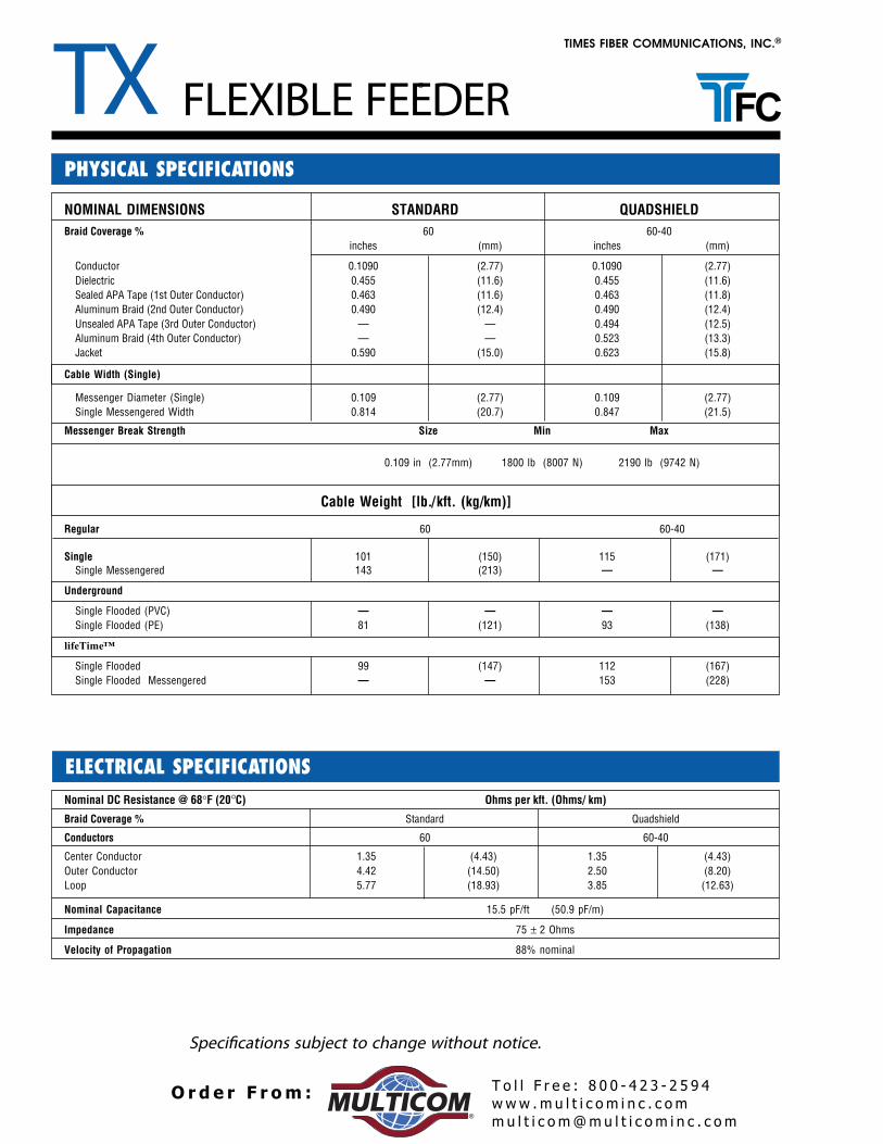
Frequency MHz dB per 100 feet dB per 100 meters
5 0.77 2.5355 1.88 6.17
211 3.59 11.78250 3.89 12.76270 4.05 13.29300 4.27 14.01330 4.50 14.76350 4.64 15.22400 4.88 16.01450 5.30 17.39500 5.50 18.04550 5.90 19.36600 6.18 20.28750 6.96 22.83870 7.54 24.75
1000 8.09 26.54
Attenuation increases with increasing temperature and decreaseswith decreasing temperature at the rate of 0.1% /°F (0.18% / °C)
NOMINAL DIMENSIONS inches (mm)
)18.0(230.0rotcudnoC)66.3(441.0cirtceleiD)68.3(251.0rotcudnoC retuO tsriF)74.4(671.0rotcudnoC retuO dnoceS)75.4(081.0rotcudnoC retuO drihT)12.5(502.0rotcudnoC retuO htruoF)56.6(262.0tekcaJ
Cable Weight, lbs per kft (kg/km) 31 (46)
ELECTRICAL SPECIFICATIONS
• Center Conductor - Silver-plated copper-clad steel forlong term low contact resistance, low attenuation andaxial strength, with easy cable preparation and reliableconnector attachment for “F” type fittings.
• Dielectric - Foam Polyethylene, low loss, high velocityproviding optimum dielectric properties. The foam isbonded to the center conductor with an easily stripped,proprietary moisture-blocking polymer.
• Outer Conductor1. Sealed APA Laminated Tape2. 95% Aluminum Braid3. APA Laminated Tape4. 95% Aluminum Braid
• Jacket - Flame retardant PVC - NEC Article 820 - “CATV
Application: Headend Cable is recommended forinstallation in headends where cable may be subjected totight bends and mechanical abuse.
DETAILS OF CONSTRUCTION AND MATERIALS
PART NUMBERS
PHYSICAL SPECIFICATIONS
HEADEND SERIES DROP CABLE
DESCRIPTIONV04220VBV-59/59QSCS95TV14220VCV-59/59QSCS95T
”
MAXIMUM ATTENUATION @ 68°F (20°C)
Ohms/1000 ft (Ohms/km)
Nominal DC Resistance at 68°F (20°C)
)0.38(3.52rotcudnoC retneC)7.11(75.3rotcudnoC retuO )8.49(9.82pooL
Nominal Capacitance 16.3 pF/ft (53.5 pF/m)
Impedance 75 ± 3 Ohms
Velocity of Propagation 83% nominal
www .m u l t i c o m i n c . c omm u l t i c o m@mu l t i c o m i n c . c om
T o l l F r e e : 8 0 0 - 4 2 3 - 2 5 9 4O r d e r F r om :®