driver’s dream cup holder - university of michiganumich.edu/~desci501/2004/apd-2004-05.pdf ·...
TRANSCRIPT

Driver’s Dream Cup Holder
Nick Magnuski Sophia Reyes Steve Strine
Marcy Urbance The intent of this project is to design a cup holder for the center console of a midsize car that is well-crafted, versatile across vehicle interiors, and holds a wide variety of cups. The optimal design will maximize profit by minimizing manufacturing cost, maximizing customer satisfaction, and maximizing segment market share. The end product will strike a balance between simplicity of design and ability to accommodate a range of cup and bottle sizes. Our proposed cup holder implements spring-loaded blocks for a variable gripping height in a relatively simple design that is easy to use.

2
TABLE OF CONTENTS 1.Introduction.................................................................................................................................. 4
1.1.1 Definition of Need ............................................................................................................. 4 1.1.2 Background/Previous Designs ........................................................................................... 4 1.1.3 Design Objectives .............................................................................................................. 7 1.1.4 Design Decisions ............................................................................................................... 7 1.2 Product Development Process .............................................................................................. 8
2. Concept Generation .................................................................................................................... 8 2.1 Concept Selection Process .................................................................................................... 8 2.3 Final Design Concept.......................................................................................................... 12 2.4 Prototype Description ......................................................................................................... 13
3. Engineering Analysis ................................................................................................................ 15 3.1 Design Variables................................................................................................................. 15 3.2 Engineering Models ............................................................................................................ 16 3.3 Engineering Optimization Study......................................................................................... 17
4. Economic Analysis ................................................................................................................... 26 5. Marketing Analysis................................................................................................................... 31 6. Additional Design Consideration.............................................................................................. 34
6.2 Ergonomics ......................................................................................................................... 36 7. Final Design Recommendations ............................................................................................... 36 8. Conclusion ................................................................................................................................ 37 References..................................................................................................................................... 38 Appendix B: QFD Chart ............................................................................................................... 40 Appendix C: Gantt Charts............................................................................................................ 41 Appendix E: Design Flowchart..................................................................................................... 43 Appendix F: Technical Analysis................................................................................................... 44 Appendix G: Engineering Model.................................................................................................. 45 Appendix H: Survey ..................................................................................................................... 47 Appendix I: Model Comparison ................................................................................................... 73 Appendix J: Business Plan............................................................................................................ 74
Business Opportunity................................................................................................................ 74 Financial Data ........................................................................................................................... 75 Supporting Documents.............................................................................................................. 76

3
Nomenclature Outer Radius R2 Number of gaps Ng Inner Radius R1 Gap size gs Height block Hb Gap variation gv Height Cup holder Hc Profit π Height of Total Device Ht Demand Q
Length of outside of block b Microeconomic Demand Qe Length of inside of block a Cost C Removable bottom inner radius Rb1 Fixed Cost Cf Removable bottom Outer radius Rb2 Variable Cost Cv Removable Bottom arc length of opening Lb Cost of wage Cw Force to wedge bottom Fwedge Cost of materials Cm Force to pull bottom Fpull Price P Stress σ Total market potential θ
Friction Force µ Price elasticity λP
Circumferential distance between blocks s Vector of design characteristic elasticitiesλd Performance Cupholding Pc Vector of design variables α Performance Ease of Use Pe Wage line worker Wl Ergonomic Performance E Wage supervisor Ws Tip Angle Фhc # of blocks Z1 Versitality V Bottom? Z2
Base wall thickness Tw Cup holder height Z3

4
1. Introduction
1.1.1 Definition of Need Johnson Controls Incorporated (JCI) has suggested that we explore an improved design including a look at craftsmanship, selected from an automotive interior. We have chosen to improve the design of a cup holder. We are designing a cup holder for the driver that will automatically adjust to container size. A new cup holder needs to be designed to adjust to various containers because there has been an increase in soft drink serving size by 52% from 1977 to 1996 resulting in bigger cups being used [2]. Therefore, there is now a greater range of cups available in the market and much of which are bigger then what the average cup holder will hold. The design will be optimized for specific engineering components and also to maximize profit. The cup holder also needs to provide versatility of use in various vehicles as well as multiple functions extending beyond a simple cup holder. Overall, we are designing a well-crafted cup holder that is easy to manufacture, service, and dispose of, to hold a wide variety of cups while not interfering with driving and other controls within the center console.
1.1.2 Background/Previous Designs Cup holders can be placed in two general categories: permanent and temporary. Permanent cup holders are available for use at any time, while temporary cup holders can be stowed away when not in use. A permanent cup holder for the driver is the primary focus of our design. In order to determine the current state of the art of cup holders different designs were researched by looking at various car cup holders, talking to users and car dealers, and conducting a patent search. To determine the current problems consumers have with their cup holder’s informal interviews with family and friends were conducted. Some of the responses to these interviews are shown in Appendix A. The major problems that were gathered from these discussions were cups tipping, too small or too large for specific cups, and in the way of controls. The Honda Accord cup holders were made adjustable by using tab devices around the cup shown in Figure 1. The Volkswagen Passat also had a similar type of design. The problem with these cup holders is that a small water bottle is not gripped by the tabs and will tip. Also the tabs in the Accord cup holder where very easy to push; therefore, a cup could easily tip back and forth within the holder. On the other hand the Passat tabs were very tight, causing Styrofoam cups to become grooved by the tabs. In this design obtaining the correct balance of tightness for the grips is a difficult issue.

5
Figure 1: Honda Accord Cup Holders [3]
A self-adjustable cup holder, US patent # 6,637,709 is another solution to cup size variability, a side view of this cup holder mechanism is show in Figure 2. The sides of the cup holder expand when a larger cup is slid into the cup holder. However, this cup holder does not support cups smaller then the original holder size and also top-heavy cups will tend to tip because the cup holder only grips the bottom of the cup [1].
Figure 2: Self-Adjustable Cup Holder US patent # 6,637,709
The cup holder shown in Figure 3 also provides some adjustability. The expanding arms of the cup holder are flimsy and can easily be caught on and broken off.

6
Figure 3: Cup Holder
A solution to an existing cup holder problem is to buy a cup holder adapter or to buy another cup holder to attach elsewhere. One example of an attachable cup holder is shown in Figure 4. This cup holder can be secured to the drivers’ side window by way of a suction cup. The adjustability is provided by having one wall slide in and out that locks in place (Patent # 5,573,214). Having an additional add on cup holder creates many problems, such as in this design if the cup weights to much the suction cup could release. Also the adjustment requires the user to use both hands for adjustment which could interfere with driving [3].
Figure 4: Window Cup Holder (Patent 5,573,214)
A more functional cup holder for the driver needs to be developed. Current cup holders only fit certain cups resulting in tipping causing inconveniences and distractions to the driver.

7
1.1.3 Design Objectives Our proposed design must satisfy the following specifications and performance:
• Accommodate a variety of sized cups ranging from a Nalgene water bottle to a pop can. • Be easy to use, in that no directions would be required to operate it efficiently • Have high performance quality • Manufacturing ease; minimal parts, ease of assembly • Versatility for use in various vehicle makes and models • Applicable for multiple uses: change tray, cell phone holder, etc. • Visually appealing, finish, and aesthetics • Ease of Maintenance and cleaning • Low cost to manufacture • Safe for hands and fingers • Durability – breakage and ring tension
Appendix B contains a Quality Function Deployment (QFD) worksheet that quantifies these specific design criterions and provides a matrix of correlations.
1.1.4 Design Decisions A number of important decisions need to be made at the design stage of the process. The relevant decisions in regards to a cup holder can be generally divided into dealing with spatial and placement issues, and specific cup holder functionality. The first category is spatial and placement. The location of the cup holder needs to be decided, and for this project such a decision space is contained to the center console. The exact volume a cup holder occupies can typically be classified as temporary or permanent. In other words, the holder can be a non-moveable feature of the interior, or it can slide, fold, or otherwise extend out from either full occlusion or to accommodate larger cups. Some examples of temporary space occupied by a cup holder are knee space, dashboard space, and arm rest space. Still within the same category, but dealing more with human interaction, are the issues of target user and task interference. A designer needs to decide whether the cup holder(s) will be used by the driver exclusively, the driver mostly, or the driver and passenger equally. Essentially, the priority of use needs to be determined. Also, the spatial location of the cup holder, especially if it is temporary, may block some tasks the driver might be performing while driving or at rest. The designer has to decide which tasks, such as operating radio controls or using the ashtray, might need to be performed in parallel with or in place of cup holder use. The second category is specific cup holder functionality. Here the designer decides both what range of uses to accommodate and how to achieve this. The spectrum of cup sizes that fit in the cup holder is determined, as is perhaps a few selected cup shapes that are most common for the target audience. Similarly, the climate and driver aggression ranges are determined. Also, the variety of other objects the cup holder might store is determined. The designer then determines how to physically hold the cups in place. This is primarily a geometric problem, but includes deciding whether to make room for mug handles and how high to grip cups and bottles when in the cup holder.

8
The designer also decides if the cup holding mechanism will be automatic or user-activated. An automatic system, which might be passive with no moving parts, simply holds the object when placed in and releases when pulled out. A user-activated system can require moving the cup holder into temporary space and/or adjustment to tailor the fit to the desired object size. The designer must then determine if such operation requires power or other forms of energy. Associated with these decisions is a tradeoff with simplicity, affecting both manufacturing and user cognitive requirements, and safety, particularly the possibility of small children getting caught in the mechanism.
1.2 Product Development Process Shown in Appendix E, is the product development process that was used in the design of the cup holder. At different points throughout the process iterations were needed. When narrowing down the possible solutions more ideas were thought of and the brainstorming phase was revisited. Also during the refining and narrowing solutions stage the design requirements needed to be rethought to make sure the most important objectives would be able to be met and other objectives were sacrificed. After the preliminary design was chosen it failed and was rejected in the verify concept step; therefore, the process began again at the brainstorm stage. Once the new design was chosen and a prototype was made, many iterations occurred between further analysis & modeling and refining the design before the second prototype was created. Further steps can be taken to create a preliminary production model and move onto the production stages if the production model is approved. The Gantt chart that was followed to complete the design development process is shown in, Appendix C.
2. Concept Generation
2.1 Concept Selection Process To evaluate the tradeoffs in our possible designs, a Pugh matrix was created (see Appendix D). Five possible solution concepts and our final design concept were generated and are explained below. Each concept was compared based on weights for each of the following design criteria:
• Durability • Cost • Ease of Manufacturing • Universality • Safety • Adjustability • Required user interaction • Novelty of design • Cleaning capability • Versatility • Reliability • Cup Hugging Ability • Quality Feel

9
After each concept was scored on each criterion the design with the highest score was chosen. The design concepts that were compared are explained and sketches are shown below. 2.2 Alternative Concepts Design six is the simplest of all the cup holders we created, shown in Figure 5. This prototype utilizes four torsion springs as the source of gripping power for the four cup grips extending from the side of the cup holder. The torsion springs are mounted on rods directly below the gripping rods. When a cup is placed in the holder the grips rotate inward about the support rods (just above the center of the torsion spring) near the top of the cup. During this rotation the torsion springs apply a horizontal force to the side of the cup holder and an equal force to the base of the grips. When the base of the cup reaches the bottom of the cup holder the grips apply horizontal forces on the sides of the cup preventing the cup from moving or tipping over while the vehicle is moving. When a large cup or bottle is placed in the holder the torsion springs are fully compressed and the grips are rotated inward 90 degrees and reside in a cavity on the side of the holder. Upon removal of a cup the grips spring back to their original horizontal position. To clean the cup holder, the grips would be rotated upward above the horizontal position. This is possible because the torsion spring is only applying force to the base of the rods, not the top. This design is both simple and easy to manufacture. However, the design is so simple it may break easily and also be perceived as cheap.
Figure 5: Design Six
Design five involves the use of gravity and a gear train for operation and is shown in Figure 6. When a cup is placed in the holder the weight of the cup pushes the false bottom downward. A notched rod attached to the center of the false bottom also moves downward through the actual base of the cup holder. As the notched rod moves downward it contacts a cylindrical gear located below the actual base of the cup holder causing it to rotate counterclockwise. Two notched rods then interface with the rotating cylindrical gear, one on the top and one on the bottom. The notched rods are each a part of a c-shaped device that moves horizontally inward as the gear rotates counter clockwise. The top portions of each c-shaped device act as grips for the cup being put in the holder by sliding through sides of the top of the cup holder and grasping the cups. When the cup is removed four compression springs below the base of the false bottom cause it to rise vertically rotating the cylindrical gear clockwise, allowing the c-shaped rods to move outward releasing the cup holder. This idea is unique because a cup’s weight is used to hold it in place. This results in less work for the user and a more sophisticated feel to the cup

10
holder. A few disadvantages of the design is that if the cup being place in the holder isn’t heavy enough to overcome the vertical force of the compression springs nothing will happen and the complicated manufacturing process involved.
Figure 6: Design Five
The fourth design is shown in Figure 7 it also involved the use of compression springs. When a cup is placed in the holder two shoe-horn shaped grips accept the cup and adjust according to the cup size. The grips adjust position by moving horizontally towards the holder walls and also through the vertical rotation of the grip. The back of each grip pivots on two horizontal rods which are connected by a compression spring to a lateral support mounted on the outside of the holder. When the grips move toward the holder walls the rods connected to the grips compress the springs attached to them creating an equal and opposite horizontal force on both sides of the cup. When the cup is removed the springs decompress returning the grips to their original position. An advantage of this cup holder is the ability of the grips to rotate and fit to the contour of the cup being placed in the holder. The simple design without many components make the cup holder cheap and easy to manufacture. One disadvantage is items may get stuck beneath the horizontal rods. It is also possible that the horizontal rods may break if a cup was placed in between a grip and the wall of the cup holder or on the grips with too much vertical force.

11
Figure 7: Design Four
The third design, Figure 8, requires no mechanical mechanisms in the functioning of the cup holder. It is designed to provide adjustability and support for a variety of beverage containers by utilizing elastic material. Traditional cup holders occupy a cylindrical shape around three inches in depth inside the center console. This holder utilizes the contour of the console between the gear shifter and the armrest between the seats. The height of the console at the gear shifter is lower than it is at the armrest so there is normally a gradient between the two locations. This holder would require a four-inch deep semi-cylindrical shape to be contoured into the gradient in the center console. A piece of leather material would then be attached to the bottom and side edges of this half cylinder forming a pouch. The leather material would have horizontal bands sewn into it so that the leather could expand depending upon the size of container placed in the holder. The elastic bands would also provide horizontal support to all containers ensuring they did not tip over or fall out when the vehicle was in motion. A positive attribute of the design is the elastic material will always adjust to the correct size of the container being placed in it. Making it very versatile, therefore it could be used for things such as change and cell phones without any risk of getting them caught. However, the elastic material may also make the design feel cheap because it may wear out too quickly. It is also possible that the leather material could be cut or ripped.
Figure 8: Design Three

12
The second design, Figure 9, employees’ circular rings and an elastic force to hold containers. There are two circular rings positioned 90 degrees apart used to support the containers inside the cup holder frame. Each ring has two mounting rods located 180 degrees apart from each other on the outside of the ring which mount into holes on the outside of the cup holder frame. The mounting rods of the smaller ring go through holes in the mounting rods of the larger ring. Both sets of mounting rings extend through the outside of the cup holder frame to the outside of the cup holder and have a short bar perpendicular to the rod centered on it. There are also two support rods, one located above the mounting rods and one located below the mounting rods, on the outside of the cup holder. On each of the support rods there are two perpendicular bars; one is located in line with the bar on the large ring mounting rod and one for the small ring. Elastic bands are placed on the bars on each mounting rod and connected to the support bars above and below them to ensure that the small and large ring rotate in an opposite directions. The static position for each ring is regulated by stops located on the bottom of the holder. The stops only allow the rings to rotate far enough so that they are separated at the top by a distance large enough to accept a pop can or a small water bottle. When a larger drink container is placed in the holder it pushes down on both rings causing them to rotate in opposite directions until the gap between them is large enough to accept the container. When the container slides between the rings the rings exert an inward force on the container attempting to return the rings to their initial static position, this is due to the elastic bands applying force to the mounting rods. It supports, adjusts to all container sizes and is very universal because of its compact size; however, the design would be a complicated manufacturing process that would result in moderate production costs. The design also fails to grip taller cups at a higher location than shorter cups.
Figure 9: Design Two
2.3 Final Design Concept The first design, Figure 10, was created by combining some of the concepts integrated into the sixth and fifth designs. This design uses three grips surrounding the cup that can travel in the vertical direction to adjust to support a variety of containers. Each grip is a hollow trapezoid. The hollow space inside each grip allows for a compression spring to fit inside. This spring is in turn connected to the base of a cavity designed to accept the vertically traveling grip. When

13
there is no force on a grip the fully extended compression spring supports the weight of the grip maintaining the grip in a full upright position. The grips are positioned relative to each other so that a pop can or thin water bottle may be placed between them without applying force to the top of any grip. However if a larger container is placed in the holder its size can be accommodated by placing it on top of anywhere from one to all three of the grips. The weight of the container will apply a downward force to the top of a grip overcoming the upward force from the compression spring causing the grips to move down into their cavities and out of the cup holding areas. Any grips that remain in their original position will act as the sides of the cup holder by applying a supporting horizontal force to the sides of the container. When the container is removed the vertical force applied by the compression springs will return them to their original position. The advantages of this design are the user doesn’t have to do a great amount of work to use it and it provides good lateral support to each container. However, this holder may be hard to keep clean and its depth of occupancy in the console may make it unusable for some cars. Also, if a lightweight container was placed on the grips it may not have enough vertical force to compress the springs or it might completely pop out of the cup holder if a large force was applied and then released.
Figure 10: Design One
2.4 Prototype Description The final design was first verified by making a quick prototype made of planting foam. This prototype is shown in Figure 11.

14
Figure 11: Foam Prototype
After the design was verified it was modeled and analyzed in ADAMS software and is shown in Figure 12.
Figure 12: ADAMS Drawing
Finally a working prototype was constructed in the machine shop in through the following processes. First the outside of the cup holder was made from PVC pipe and cut to dimension using a band-saw. The removable bottom and base of the holder were then designed in Bob-CAD and created out of Plexiglas using a laser cuter. Next springs were created using a device that tensioned and coiled small diameter music wire because the ones our design required could not be purchased. Following the creation of springs, three screws were screwed in the holder base and then fitted with hollow rods of Plexiglas to be used as spring supports. The buttons and removable bottom supports were then made by lathing, boring, and band-sawing a piece of round UHMW polyethylene. After the buttons were created a hole for the spring and spring support

15
was drilled in each one of them. Next the removable bottom supports were attached to the holder base by screws. Final assembly included placing the springs in the drilled out button cavities, placing each button on a spring support, and then placing the PVC around the interior holder pieces. Some of the major problems encountered in prototyping were making the springs, and cutting the buttons properly to fit their cavities. Creating springs with a coefficient of stiffness that allowed them to support one button, but also be forced down by an empty container was difficult and not fully achieved. While creating the springs it was a challenge to maintain proper tension and spacing for each coil to produce the ideal product. When the buttons were cut on the band-saw there were problems keeping the button material flush against the band-saw table because of the torque on the piece from the cutting blade. This resulted in some crooked button pieces which had to be re-cut and sanded so that they we fit and function properly in their cavities. After overcoming obstacles such as these the final prototype became a working device that accomplished most of its desired design objectives with great consistency. A picture of the final prototype can be seen in Figure 13.
Figure 13: Final Prototype
3. Engineering Analysis
3.1 Design Variables In this project we have limited our cup holder to a permanent space in the center console, and have selected a preliminary functional design. Therefore the primary design variables concern the cup holder geometry and material selection.

16
Geometry variables are as follows:
• Depth and diameter of the base hole • Depth of cup holding space • Inner diameter made by blocks • Height and width of the blocks • Radial spacing and arrangement of the blocks • Removable bottom dimensions
Material selection variables are as follows:
• Block material • Spring tension
Other variables we have considered but left as parameters might be investigated in a more technical analysis or for specific manufacturing concerns. Some of these include:
• Location of base hole within the console • Block thickness • Spring free and compressed length • Pull tab dimensions • Curvature of true bottom • Height and diameter of spring post • Block color
3.2 Engineering Models The four engineering models identified for analysis in this project are mechanics, dynamics, ergonomics, and craftsmanship. Mechanics analysis will be used to examine the strength and durability of the sliding blocks and springs. The blocks will be under stress laterally when a cup or bottle is wedged in, and will experience a number of distributed and point loads when an object pushes them downwards. The block surface friction with the cups could also be considered, as well as spring strength. Models from dynamics will help assess block geometry, spring strength, and cup holder performance when the car is in motion. The block height and width, listed as design variables above, will be partially dependent on the optimal gripping height of the determined range of cups. This, in turn, will depend on a 2DOF analysis of lateral forces likely to be experienced during normal driving. The spring choice will also impact the kinetic energy stored when a user pushes blocks down with a cup. Ergonomic studies will ensure proper interface with the driver and passenger. Human “down strength” will be evaluated in determining the stiffness of the springs within the blocks. The cup holder mechanism needs to be examined with respect to child safety, for example to prevent a child’s hand from getting stuck.

17
Craftsmanship metrics should also guide the design of the cup holder. To allow a seamless integration with the visual flow of the cockpit, the cup holder geometry and material selection will need to be considered. As these are product characteristics (and design variables in this project), the relevant perceived attributes will need to be identified and matched with customer input from the research phase.
3.3 Engineering Optimization Study The optimal cup holder will ideally fulfill the many design requirements listed previously page 7. However, since most of the requirements stated are qualitative in nature, and the analytic approach to design taken here dictates quantitative variables, parameters, and overall measures of requirement satisfaction, the quantitative and qualitative must be bridged. The first step is to consider the objectives of the cup holder project from an engineering standpoint. The several design requirements can be generally grouped into the following five categories:
1. Performance (Cup Holding) 2. Performance (Ease of Use) 3. Ergonomics 4. Versatility 5. Craftsmanship
To avoid any confusion in later text, the term versatility is taken to mean ease with which the cup holder can be mounted without modifications in various vehicles. While these objective categories are still highly qualitative, they will provide a context for the following discussion of model variables and parameters. The geometry alone of a cup holder such as ours contains dozens of dimensions that could be treated as variables. The relevant variables can be extracted by referring again to the QFD in Appendix B. Looking at the normalized importance scores, it can be seen cup holder width and depth are key, as are block dimensions. Also, to capture ergonomic and craftsmanship characteristics, removable bottom dimensions will be considered. Thus there are eight variables in this model:
Table 1: Design Variables VARIABLES name value unitOuter Radius R2 1.975 inchInner Radius R1 1.375 inchHeight Cup holder Hc 4 inchLength of outside of block b 0.875 inchLength of inside of block a 0.75 inchremovable bottom inner radius Rb1 1.38 inchremovable bottom Outer radius Rb2 1.81 inchRemovable Bottom arc length of opening Lb 0.88 inch
Shown are nominal values, as well as units. The short list of variables is made up for by an extensive list of parameters:
18
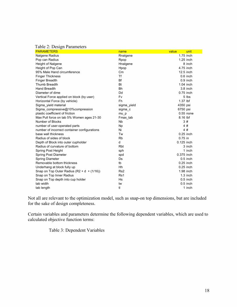
Table 2: Design Parameters PARAMETERS name value unitNalgene Radius Rnalgene 1.75 inchPop can Radius Rpop 1.25 inchHeight of Nalgene Hnalgene 8 inchHeight of Pop Can Hpop 4.75 inch95% Male Hand circumference Cm 12.5 inchFinger Thickness Tf 0.6 inchFinger Breadth Bf 0.9 inchThumb Breadth Bt 1.04 inchHand Breadth Bh 3.8 inchDiameter of dime Dd 0.75 inchVertical Force applied on block (by user) Fv 5 lbsHorizontal Force (by vehicle) Fh 1.37 lbfSigma_yield material sigma_yield 4350 psiSigma_compressive@10%compression sigma_c 6750 psiplastic coefficient of friction mu_p 0.55 noneMax Pull force on tab 5% Women ages 21-30 Fmax_tab 8.16 lbfNumber of Blocks Nb 3 #number of user-operated parts Np 4 #number of incorrect container configurations Ni 4 #base wall thickness Tw 0.25 inchRadius of sides of block Rb 0.75 inDepth of Block into outer cupholder d 0.125 inchRadius of curvature of bottom Rbt 3 inchSpring Post Height sph 1 inchSpring Post Diameter spd 0.375 inchSpring Diameter Ds 0.5 inchRemovable bottom thickness tb 0.25 inchUnderhang at block fully up Hh 0.25 inchSnap on Top Outer Radius (R2 + d + (1/16)) Rs2 1.98 inchSnap on Top Inner Radius Rs1 1.3 inchSnap on Top depth into cup holder Hs 0.5 inchtab width tw 0.5 inchtab length tl 1 inch
Not all are relevant to the optimization model, such as snap-on top dimensions, but are included for the sake of design completeness. Certain variables and parameters determine the following dependent variables, which are used to calculated objective function terms:
Table 3: Dependent Variables

19
DEPENDENT VARIABLES name value unitApproximated Area of block, A= ((b+a)/2)* (RA 0.59 inch^2Inner Circumference C1 8.64 inchOuter Circumference C2 12.41 inchcircumferential distance between blocks s 3.24 inchtab pull force Fpull 0 lbfnumber of gaps Ng 19 #gap size gs 0 inchgap variation gv 0 inchHeight block Hb 4.25 inchHeight of Total Device Ht 8.5 inch
Tab pull force is derived as follows: A wedge force can be produced in the removable bottom if Rb2>R2:
( )stR
RRF b
b
bcwedge ⎟⎟
⎠
⎞⎜⎜⎝
⎛ −=
2
22σ
The pull force is in turn calculated as: wedgecpull FF µ= Gap count, size, and variation are functions mainly of the number of blocks, and the tolerance between the removable bottom and the block outer perimeter. For example,
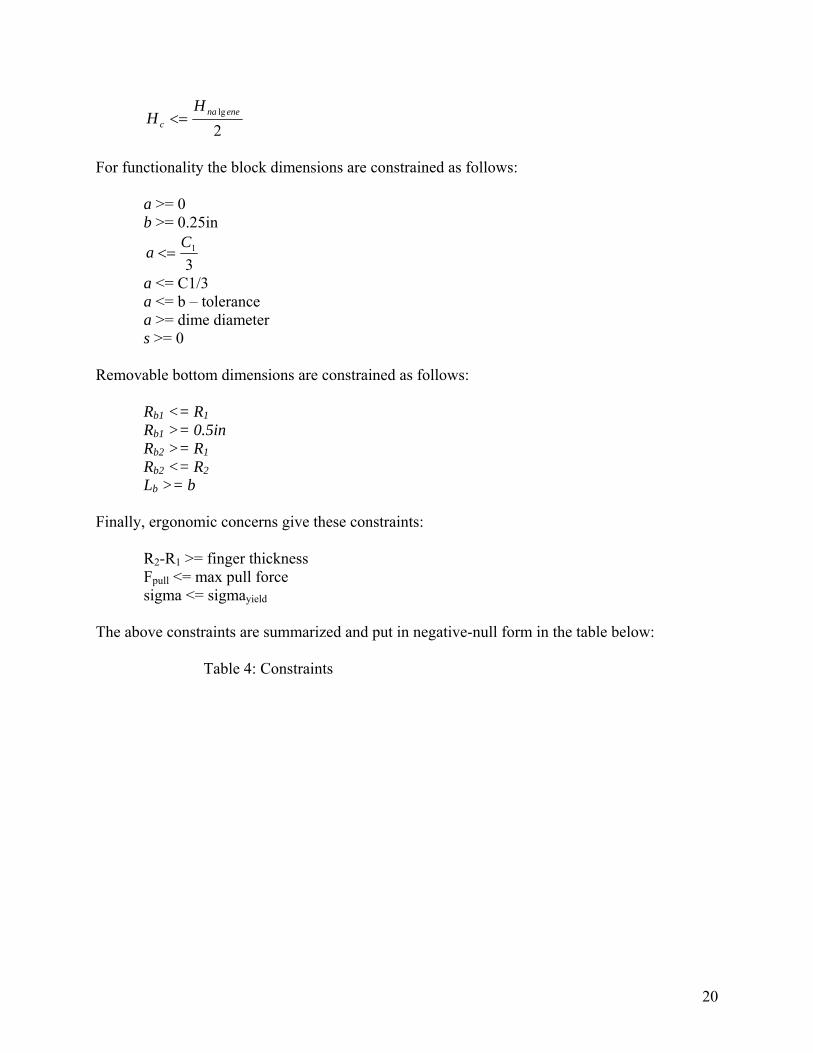
gap size = max[(Lb-b),(R1-Rb1)] Next the model constraints must be determined. Using a Nalgene bottle and a pop can as two cup holding design standards, the first constraints are:
outer radius >= Nalgene radius + tolerance inner radius >= pop can radius + tolerance
where the tolerance is assumed one eighth inch. To avoid making the unit too wide, outer radius <= 2.25in Also, dimensionally, outer radius >= inner radius inner radius >= 0 Cup holder height is also constrained from above:
20
2lg enena
c
HH <=
For functionality the block dimensions are constrained as follows: a >= 0 b >= 0.25in
31C
a <=
a <= C1/3 a <= b – tolerance a >= dime diameter s >= 0 Removable bottom dimensions are constrained as follows: Rb1 <= R1 Rb1 >= 0.5in Rb2 >= R1 Rb2 <= R2 Lb >= b Finally, ergonomic concerns give these constraints: R2-R1 >= finger thickness Fpull <= max pull force sigma <= sigmayield The above constraints are summarized and put in negative-null form in the table below:
Table 4: Constraints
21
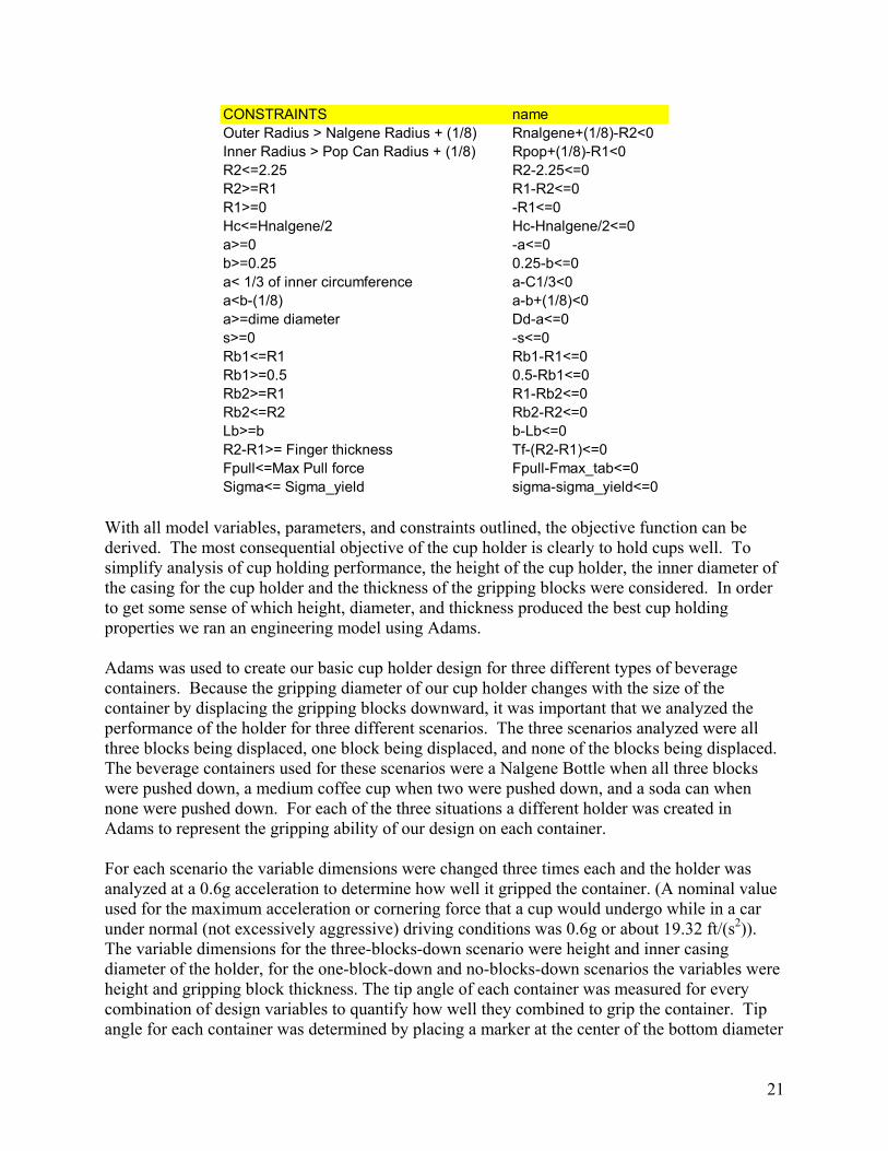
CONSTRAINTS nameOuter Radius > Nalgene Radius + (1/8) Rnalgene+(1/8)-R2<0Inner Radius > Pop Can Radius + (1/8) Rpop+(1/8)-R1<0R2<=2.25 R2-2.25<=0R2>=R1 R1-R2<=0R1>=0 -R1<=0Hc<=Hnalgene/2 Hc-Hnalgene/2<=0a>=0 -a<=0b>=0.25 0.25-b<=0a< 1/3 of inner circumference a-C1/3<0a<b-(1/8) a-b+(1/8)<0a>=dime diameter Dd-a<=0s>=0 -s<=0Rb1<=R1 Rb1-R1<=0Rb1>=0.5 0.5-Rb1<=0Rb2>=R1 R1-Rb2<=0Rb2<=R2 Rb2-R2<=0Lb>=b b-Lb<=0R2-R1>= Finger thickness Tf-(R2-R1)<=0Fpull<=Max Pull force Fpull-Fmax_tab<=0Sigma<= Sigma_yield sigma-sigma_yield<=0
With all model variables, parameters, and constraints outlined, the objective function can be derived. The most consequential objective of the cup holder is clearly to hold cups well. To simplify analysis of cup holding performance, the height of the cup holder, the inner diameter of the casing for the cup holder and the thickness of the gripping blocks were considered. In order to get some sense of which height, diameter, and thickness produced the best cup holding properties we ran an engineering model using Adams. Adams was used to create our basic cup holder design for three different types of beverage containers. Because the gripping diameter of our cup holder changes with the size of the container by displacing the gripping blocks downward, it was important that we analyzed the performance of the holder for three different scenarios. The three scenarios analyzed were all three blocks being displaced, one block being displaced, and none of the blocks being displaced. The beverage containers used for these scenarios were a Nalgene Bottle when all three blocks were pushed down, a medium coffee cup when two were pushed down, and a soda can when none were pushed down. For each of the three situations a different holder was created in Adams to represent the gripping ability of our design on each container. For each scenario the variable dimensions were changed three times each and the holder was analyzed at a 0.6g acceleration to determine how well it gripped the container. (A nominal value used for the maximum acceleration or cornering force that a cup would undergo while in a car under normal (not excessively aggressive) driving conditions was 0.6g or about 19.32 ft/(s2)). The variable dimensions for the three-blocks-down scenario were height and inner casing diameter of the holder, for the one-block-down and no-blocks-down scenarios the variables were height and gripping block thickness. The tip angle of each container was measured for every combination of design variables to quantify how well they combined to grip the container. Tip angle for each container was determined by placing a marker at the center of the bottom diameter

22
and plotting the movement of the marker in the vertical direction during acceleration. The maximum vertical displacement for each container was then used in combination with its base diameter to quantify a maximum tipping angle.
Figure 14: Performance Model Diagram
The data produced from completing this simulation was analyzed to determine if there is the general effect that changing each of the design variables had on the tip angle of each container. The general results for the scenarios were that as holder height increases and the inner diameter of the holder’s gripping surface becomes closer to the maximum outside diameter of the container, less tip angle occurs. We treated tip angle as a measurement of how much rotational momentum the container has to flip out of the holder when a hard deceleration occurs. Rotational momentum is important because when the container hits the inner edge of the holder the horizontal momentum from mass in the container that is above the highest contact point between the container and the holder will translate to rotational momentum. The rotational momentum then causes the container to rotate around the highest contact point between the holder and container, leading to the tip angle. If the point of contact between the holder and container is too low the rotational momentum will cause the container to rotate out of the container. A tight fit inner diameter helps prevent rotation of the container out of the holder because the back end of the container contacts the back edge of the holder creating a counter torque to offset some of the rotational momentum. In order to complete an engineering analysis with the data obtained we plotted tip angle vs. both inner gripping diameter and holder height. For each scenario tested we used linear regression analysis to determine a best fit line for tip angle vs. holder height as inner gripping diameter varied, and for tip angle vs. inner gripping diameter as holder height varied. Plots of these scenarios are given here:
Figure 15: Tip Angle Plot
Rear
Base
Highest Contact Point
Tip
Vertical
Rear

23
tan(tip angle) vs. Hc
00.020.040.060.080.1
0.120.140.160.18
0 1 2 3 4 5
Hc
nalgene1
Pop Can
Coffee Cup
nalgene2
nalgene3
Figure 16: Tip Angle Plot lateral tip vs. D2
00.020.040.060.080.1
0.120.140.160.18
3.5 3.7 3.9 4.1 4.3 4.5 4.7D 2
Nalgene
Coffee Cup
Figure 17: Tip Angle Plot lateral tip vs. D1
00.010.020.030.040.050.060.070.080.090.1
2.5 2.7 2.9 3.1 3.3 3.5D 1
Pop Can
Coffee Cup
Note that D2 is twice R2, and similar for D1. It was assumed correlation between the three variables was minimal. Fitting linear trend lines to these data is a gross approximation; however,

24
the trends are consistent and believable and given the time frame of this project, many simplifications are necessary. The three trend lines resulting from the above three plots give tip angle as a function of Hc, R1, and R2. For example: )(tan 1
HccHcHc bHm += −φ The first objective function, Performance (cup holding), is then calculated as: ( )21 RRHccP φφφ ++−= The next objective function, Performance (ease of use), minimizes the complexity of the design and maximizes finger clearance. This can be stated as: Pe = -# parts - # incorrect uses + block separation In terms of the model variables and parameters, Pe = -Np – Ni + s The Ergonomics objective function attempts to minimize the pull force necessary to remove the bottom plate, as well as maximize the outside radius to avoid hands getting wedged: E = -Fpull + R1 Versatility is a sum of the total unit depth and the total unit diameter. Minimizing this will increase the ability to fit the Driver’s Dream in a multitude of vehicle platforms. V = –true depth – (outer diameter + wall thickness) Or, V = –Ht – (R2+Tw) Finally, Craftsmanship looks at gaps formed between the blocks and the removable bottom: C = –#gaps – gap size – gap variation In terms of model variables, C = –Ng – gs – gv Having defined all five objective functions, a basic monotonicity analysis demonstrates relationships between model variables and each objective. The following table also lists relevant dependent variables:

25
Table 5: Monotonicity Pc (+) Pe (+) E (+) Vr (+) Cr (+)
1 Outer Radius R2 - + -2 Inner Radius R1 - + +3 Height Cup holder Hc + +4 Length of outside of block b - -5 Length of inside of block a - -6 removable bottom inner radius Rb1 - +7 removable bottom Outer radius Rb2 +8 Removable Bottom arc length of opening Lb -
circumferential distance between blocks s + +tab pull force Fpull -number of gaps Ng -gap size gs -gap variation gv -Height of Total Device Ht - -
Each of these objective functions was modified slightly to give values roughly within a range of 10. The model objective function is then a weighted sum as follows: f = 10Pc + 5Pe + E + V + C The reasoning behind these weights are to emphasize the true purpose of the cup holder in that it serves to hold beverage containers, to increase the importance of ease of use, and to give equal consideration to ergonomics, versatility, and craftsmanship. Certainly these weights and this objective strategy is subjective and somewhat arbitrary. These weights could be tuned in further studies to reflect marketability, or upscale target audience, for example. The objective function is summarized here:
Table 6: Objective Function Summary OBJECTIVEmax engineering performance Pc+Pe+E+V+CPerf(cupholding) -(phi_Hc+phi_R1+phi_R2)Perf(easeofuse) -Np-Ni+sErg -Fpull+R1Vers -Ht-(R2+Tw)Craft -Ng-gs-gv
To find the optimal values for the eight variables, the model was optimized in Excel using the built-in Solver tool. A summary of results is given in the following table:
Table 7: Optimized Design Values

26
Engineering Optimized DesignR2 1.975R1 1.375Hc 4b 0.875a 0.75Rb1 1.375Rb2 1.81Lb 0.875
Full details of constraint activity and variable sensitivity are shown in Appendix G. At optimality the solution is bounded by:
• minimum radius of a pop can • maximum half-height of a Nalgene bottle • minimum clearance for fingers • block trapezoidal requirement • small change requirement • block/removable bottom interface
Sensitivity analysis shows an overwhelming dependence on the minimum inner radius as constrained by the pop can radius. This is due in part to the tip angle analysis in cupholding performance, although decreasing R1 would destroy the functionality of the cupholder. So far the cup holder height has been relatively unconstrained. In the next sections the impact of Hc on profit and cost will better characterize this important variable.
4. Economic Analysis The first step in the economic modeling was to determine a market size. Because cup holders represent at least a small portion of the cockpit in every vehicle, the target market was narrowed to vehicles with a center console contiguous with the dashboard, yet large enough to accommodate a design of this volume. Thus the midsize car segment was chosen, with 2003 sales as a continuous measure of demand. In actuality the demand would be discretized into specific models by manufacturer: for more discussion on this topic, refer to the business plan in Appendix J. Segment sales were taken from [6] and are shown in the table below:
Table 8: Midsize Car Sales Figures (2003) MIDSIZE Camry 413000 Accord 397000 Taurus 300000 Impala 267000 Altima 201000
Grand Am 156000 Malibu 122000 Sebring 100109
27
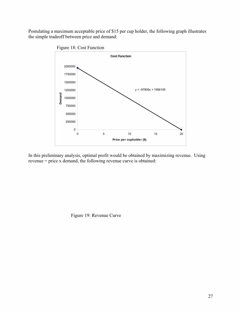
Postulating a maximum acceptable price of $15 per cup holder, the following graph illustrates the simple tradeoff between price and demand:
Figure 18: Cost Function
Cost Function
y = -97805x + 1956109
0
250000
500000
750000
1000000
1250000
1500000
1750000
2000000
0 5 10 15 20
Price per cupholder ($)
Dem
and
In this preliminary analysis, optimal profit would be obtained by maximizing revenue. Using revenue = price x demand, the following revenue curve is obtained:
Figure 19: Revenue Curve

28
Revenue
0
1000000
2000000
3000000
4000000
5000000
6000000
7000000
8000000
9000000
10000000
0 5 10 15 20
Price per cupholder ($)
Rev
enue
($)
Here it can be seen the optimal price is $10.00 for maximum revenue. This value will only be used as a base design price, for comparison with optimization results. In actuality the profit is a function of Demand, Price, and Cost:
CQP −=∏ )( The profit equation can be expanded further to show dependency on the price and design variables. This is stated as:
CPP TdP −∆+−=∏ )~~( αλλθ
where Π is profit, P is price, θ is total market potential, λP is price elasticity, λd is a vector of design characteristic elasticities, α is a vector of design variables, and C is cost. With a cup holder it is very difficult to directly translate design variables into product characteristics that effect how the user perceives the product and how inexpensive the product is to manufacture. For this analysis the cupholder height, Hc, will be used in both the function for Demand and the function for Cost to represent an elementary tradeoff between design functionality and cost. Looking first at revenue as a function of P and Hc, the total market potential and price elasticity have already been estimated from the Cost Function in Figure 18 above. Thus:
θ = 1,956,109 λP = 97,805
Cup holder height can be related to demand by assuming a greater height accommodates a larger range of containers, and will therefore translate into increased market share and customer satisfaction. Assuming cup holder depths are normally distributed about a value roughly half the height of the pop can, maximum market share multiplied by the cumulative function gives the total sales. The design variable of cup holder height was used as operating variable, and for the normal distribution a mean of 2” and a standard deviation of 1” was assumed. For example, the
29
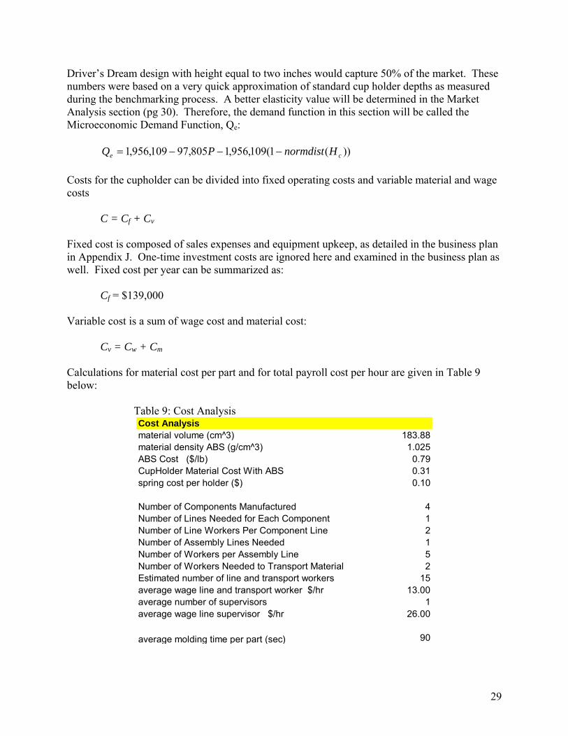
Driver’s Dream design with height equal to two inches would capture 50% of the market. These numbers were based on a very quick approximation of standard cup holder depths as measured during the benchmarking process. A better elasticity value will be determined in the Market Analysis section (pg 30). Therefore, the demand function in this section will be called the Microeconomic Demand Function, Qe:
))(1(109,956,1805,97109,956,1 ce HnormdistPQ −−−= Costs for the cupholder can be divided into fixed operating costs and variable material and wage costs C = Cf + Cv Fixed cost is composed of sales expenses and equipment upkeep, as detailed in the business plan in Appendix J. One-time investment costs are ignored here and examined in the business plan as well. Fixed cost per year can be summarized as: Cf = $139,000 Variable cost is a sum of wage cost and material cost:
Cv = Cw + Cm Calculations for material cost per part and for total payroll cost per hour are given in Table 9 below:
Table 9: Cost Analysis Cost Analysismaterial volume (cm^3) 183.88material density ABS (g/cm^3) 1.025ABS Cost ($/lb) 0.79CupHolder Material Cost With ABS 0.31spring cost per holder ($) 0.10
Number of Components Manufactured 4Number of Lines Needed for Each Component 1Number of Line Workers Per Component Line 2Number of Assembly Lines Needed 1Number of Workers per Assembly Line 5Number of Workers Needed to Transport Material 2Estimated number of line and transport workers 15average wage line and transport worker $/hr 13.00average number of supervisors 1average wage line supervisor $/hr 26.00
average molding time per part (sec) 90

30
In the above calculations, wage cost is assumed a function of Hc. Cup holder height can be related to assembly difficulty, and thus the number of workers required to assemble the device. Therefore the number of workers on the assembly line scales from 2 to 5 relative to Hc. Inputting demand into the model produces first the material cost:
Cm = $0.41(Q) Research into manufacturing methods led to the determination that the injection-molding process would be the bottleneck of the Driver’s Dream production. Therefore, man-hours required are found by dividing demand by average molding time per part as given in Table 9 above. Cw can now be rewritten as:
)(160 slw WWQC +=
where Wl is line worker wage and Ws is supervisor wage. Assuming there is one supervisor necessary, Wl and Ws are calculated:
)1(26$
))11(13$=
+=
l
cl
WHW
To restate briefly, Cost is given by: C = Cf + Cm + Cw With the groundwork laid for interdependencies between Price, Demand, and Cost, the next step is to re-optimize the Driver’s Dream Cup Holder to maximize profit. With the additional variable of price added since the construction of the engineering optimization model, two new constraints are added to provide reasonable upper and lower bounds: P >= $5 P <= $15 Furthermore, the model was simplified to speed calculations and shift focus to the relevant variables. For this analysis the height of the block, Hb, was assumed equal to the sum of the cup holder height, Hc, and the removable bottom thickness, tb: Hb = Hc + tb Then total cup holder height, Ht, was set to the sum of Hb and Hc: Ht = Hb + Hc Results of the optimization are shown in Table 10 below:

31
Table 10: Economic Model Results our design optimal for profit(Hc=4",P=$10)
profit 7,524,336$ 7,568,004$ revenue 9,335,570$ 9,262,175$
cost 1,811,234$ 1,694,170$ price $10.00 $10.67
#blocks 3 3rem. bottom 1 1
height 4.00 4.00demand 933,557 868,204
For comparison they are presented next to the Cost, Revenue, and Profit figures resulting from the design given by the Engineering Analysis. Constraint activity is identical to that for the Engineering Model. Changes from the engineering-optimized design are minor, only a slight increase in price per unit. However, this result was predictable: the model of demand using a normal distribution forces assignment of parameters to define the distribution. Without market data the chosen values conveniently cause the optimization results to roughly agree with the old design. A more in-depth study of market forces and another look at the relevant design variables will be covered in the next section.
5. Marketing Analysis Given the previous exploration of the economic fundamentals in the context of Driver’s Dream design, a more analytical and meaningful relationship between design characteristics and customer demand is needed. Assuming the target market is still midsize autos as detailed in the previous section – except that now a more realistic goal of 50% of the market is set – what elements of the design and price are most important to the customer and what values will maximize customer satisfaction (and thus profits)? Clearly the cup holder height, Hc, is a critical design variable. However, in this section two more characteristics, as well as price, will be evaluated to gage marketability. The first characteristic is number of blocks, or Nb. Our nominal design assumes three blocks based on flexibility in adapting to various container sizes. To determine if customers are willing to pay for more or would prefer less, Nb was opened to discrete values of 0, 2, 3, and 4. The second characteristic is the removable bottom. This will become a binary variable, i.e. a removable bottom is either present (1) or not (0). Obviously both these characteristics are not specifically design variables as defined in the Engineering Analysis, as both are inherently discrete. Yet they capture important aspects of the cup holder functionality and using Discrete Choice Analysis it will be shown they can be quantitatively linked to product demand. The first step in our DCA study was to conduct a survey of classmates. For this, levels for each of the aforementioned characteristics, as well as price, were determined and are shown in Table 11 below:

32
Table 11: Characteristic Levels symbol w=1 w=2 w=3 w=4
p $5 $10 $15z1 0 blocks 2 blocks 3 blocks 4 blocksz2 w/o bottom w/bottomz3 Hc=2" Hc=3" Hc=4"
where z1 is # blocks, z2 is removable bottom, and z3 is cup holder height. A partial-factorial question structure was designed using SAS software, and the survey was administered to roughly 36 respondents. The survey can be found in Appendix H. Using the Logit Model, part-worths for the characteristic levels, and a no-choice option, were calculated and are summarized in the following table:
Table 12: Part Worths w=1 w=2 w=3 w=4
p 0 -0.654017 -1.403981z1 0 1.455087 2.155793 2.210517z2 0 1.199142z3 0 0.731445 0.430609NC 1.718538
These part-worths give utility at the discrete characteristic levels. With the goal of eventually returning to optimization in Solver, spline interpolation was used to approximate product utility as a continuous function of characteristic value. A sample calculation of product demand based on given characteristic values is shown below:
Table 13: Demand Sample Calculation value utility
p $12.00 -0.94z1 3 2.16z2 1 1.20z3 2.8 0.67total utility of new product 3.08
utility of no choice 1.72
Pr(our product) 79.60%Pr(no choice) 20.40%
market size 1956109monopoly demand 1,557,116
50% of market 778,558 This method can be iterated to find design elasticities for each of the characteristics. The following graphs represent these elasticities, with trend lines fit:

33
Figure 20: Product Characteristic Elasticities lambda_P
y = -22093x + 995520
300
400
500
600
700
800
900
$5 $7 $9 $11 $13 $15
lambda_z1
y = 11929x3 - 174930x2 + 785421x - 315514
300
400
500
600
700
800
900
1 2 3 40
lambda_z2
y = 245470x + 541117
300
400
500
600
700
800
900
0 1non-removable removable
lambda_z3
y = -79634x2 + 512314x + 9924.8
300
400
500
600
700
800
900
2.00 2.50 3.00 3.50 4.00
Comparing first the price elasticity to that estimated in the Economic Analysis, it can be seen here that demand drops more than four times less rapidly with price. On the one hand, it is possible the survey did not fully explain the consequences of price considering the number of units produced. On the other hand, the original price elasticity was calculated using somewhat artificial price boundaries. The demand elasticity for Hc is shown to be vastly different from the cumulative normal distribution function employed in the Economic Analysis. Here demand peaks near 3.2”, and has less variability across the range of cup holder heights. Demand elasticity for number of blocks was modeled as a complex polynomial, but the important trend is that four and three blocks lend roughly equal demand, with an almost linear drop-off below. Also, a removable bottom is clearly demonstrated as a customer-preferred characteristic. To re-optimize the design for profit, the demand is tied to product characteristics via utility as in the calculations above (Table 13 & Figure 20). Returning to the elementary profit equation: CQP −=∏ )(

34
Qm, the Marketing Demand Function, is now a function of P, z1, z2, and z3, and cost is a function of z3 as before. Yet the new model cannot be directly input into Solver since z1 and z2 are inherently discrete. Instead of enumerating all cases by complex parametric study, the design space can be limited by examining the elasticities. First, a removable bottom yields an obvious advantage over a non-removable bottom, so all cases where z1=0 can be eliminated. Second, a cup holder with zero or two blocks is far less preferable than one with three or four, so the possibilities are again cut in half. What remains are two parametric studies:
• z1 = 1 • z2 = 3 or 4 • z3 is variable • price is variable
This is in a form that can be handled by Solver. Results of the two cases are presented below:
Table 14: Marketing Parametric Study Results parametric study 1 optimal for profit parametric study 2 optimal for profit(#blocks = 3) (#blocks = 3) (#blocks = 4) (#blocks = 4)
profit 6,317,896$ 9,317,002$ 6,385,914$ 9,455,814$ revenue 7,865,870$ 10,685,100$ 7,948,730$ 10,841,955$
cost 1,547,974$ 1,368,098$ 1,562,816$ 1,386,141$ price $10.00 $15.00 $10.00 $15.00
#blocks 3 3 4 4rem. bottom 1 1 1 1
height 4.00 3.19 4.00 3.19demand 786,587 712,340 794,873 722,797
In both cases the optimization algorithm finds a greatly improved design, albeit through maximizing the price and setting Hc to the value representing the peak of the design elasticity curve in Figure 20 above. On the surface, a four-block design seems to have an advantage as it produces approximately $140,000 more profit. However, this highlights a limitation of the model: the relatively simple cost model does not account for expense derived by adding blocks. This increase in complexity without penalty is probably unrealistic, and further analysis would need to account for such tradeoffs. A final comparison of all design iterations and the resulting changes in profit, etc. can be found in Appendix I.
6. Additional Design Consideration 6.1 Impact of Product The design of the Drivers Dream Cup Holder is intended to have a positive impact on all that it affects. Throughout the design process we kept in mind the environmental and human interaction effects our product would have. There has become a growing concern for the future of our natural resources. Also the society within which we manufacture our product will be
35
impacted. It has been estimated up to 80% of the environmental impact of a product is determined during the design stage [4]. As designers we must take into account these issues when choosing materials for our product, determining the ease of assembly and disassembly, the ability to recycle the product after use, and consumer safety during use of the product. We have chosen to use ABS as the material of which to manufacture our cup holder. Since we are purely composing the cup holder out of ABS it can easily be reused for other purposes. The recycle ability of ABS is growing based on a study: Composition, Properties and Economic Study of Recycled Refrigerators, from PlasticsResource.com information on plastics and the environment. The data they collected clearly indicate that the value of recovered plastics, particularly ABS, will increase [5]. Thus, we are confident that the use of this material will be effective in terms of our responsibilities to consumers, society and the environment. Another aspect of environmental impact is the ease of disassembling the cup holder for recycling. The design of the cup holder was created with ease of assembly and disassembly in mind. We designed the snap on top for ease of removal from the center consol and easy access to the inside mechanics of the cup holder. This is for the purpose of fixing and more importantly for the disassembly of the product at the end of its life time for recycling. To ensure that the cup holder is easy to disassemble for recycling we have also minimized the materials used. This is important to mention again since with only one material, minus the springs, the cup holder does not need to be completely broken apart. We have successfully created a product that can be easily recycled, yet is still functional. Another environmental issue is to design the manufacturing process to be as safe as possible. This includes materials that are environmentally friendly, as previously mentioned. This will prevent spills and leaks of various toxic chemicals and will prevent harmful fumes. Also the manufacturing design includes minimal emissions and utility use; thus minimizing air and water pollution. Also, in designing the manufacturing process, waste and scrap materials should be prevented as much as possible. Through the process of injection molding we have prevented the possibility of scraps that can ultimately have an adverse effect on the environment. The design must also be tailored to the needs of the consumer and the capacities of the manufacturer. These human interactions with the cup holder are based on the manufacturability, and usability of the product. The society of the area within which the cup holder is being manufactured will also be impacted due to an increase of jobs. The manufacturing process we have designed includes 16 workers paid a substantial wage in proper working conditions provided by Johnson Controls Inc. The human interaction during the manufacturing process should be a positive experience given that the cup holder is fairly easy to assemble. The use of cup holders while driving has been the cause of many accidents in the United States. We hope to decrease this concern with an automatically adjustable cup holder large enough for a Nalgene bottle. The consumer using the cup holder will find it easy to operate and thus have a lower potential to cause accidents while using it. In effect we will decrease the number of negative human interactions and generate safer driving circumstances.

36
We have designed out cup holder to produce a positive impact on both the environment and human interactions, to the best of our knowledge. Ultimately, our design reflects good judgment and values that we maintain as citizens of this society.
6.2 Ergonomics In designing the Driver’s Dream cup holder anthropometric data was used to determine some of the dimensions. The size of a 95th percentile male’s fist was taken into account so that a man could place their whole fist in the cup holder when the buttons are depressed. This will aid in cleaning. It was also important that fingertips would fit between a soda can and the side walls of the cup holder, this helped determine the width of the buttons. Some other measurements that took ergonomics into account were the cup holders total height, so that the bottom could be reached by as many people as possible. Also the finger grips for the removable bottom need to be large enough for a male to pull it out. A person also must be able to create the grip force between a finger and the thumb to pull out the bottom.
7. Final Design Recommendations The Final design of the Drivers Dream Cup Holder has accomplished our original goal. We set out to design an adjustable cup holder that accommodates a variety of sized cups ranging from a Nalgene water bottle to a pop can. We also designed our cup holder to be easily manufactured, easy to use, and easy to maintain and clean, as well as versatile among various vehicles. We also anticipate that our cup holder will be applicable for multiple uses such as a change tray or a cell phone holder. The design of our cup holder is also safe for all sized hands and fingers as well as durable to withstand the downward forces of constant usage. We have accomplished all of these specifications within our single design. Our final design has three push down blocks, a removable bottom for easy cleaning, and a height of 3.2 inches. These have been determined through engineering, marketing, and economic analyses. We conducted a survey for the marketing analysis and found that among the people surveyed they preferred a low cost product with three support blocks, a removable bottom, and at least a 3.2 inch depth of the cup holder. However, we failed to include a brief description of our prototype, we assumed that our audience had a good idea of what we were interested in from visually seeing our prototype. People may have assumed that they were buying this cup holder for themselves, while in fact we would have liked them to take the perspective of a car manufacturer buying a large quantity of cup holders. Overall, the surveyed audience prefered the low cost but not as strongly as the economic analysis showed. These helped to support our decision on specific dimensions and critical aspects of our cup holder. The material we recommend for manufacturing our cup holder is Acrylonitrile Butadiene Styrene (ABS). We chose this material because it is the material most often used to produce the center console area where our cup holder would be placed. We initially set out to achieve better craftsmanship of cup holders and found it difficult to demonstrate in our prototypes given limited resources. A good prototype would have accelerated the craftsmanship analysis of the cup holder. However, we intend the actual finished design to be more precise and of better quality due to the manufacturing process of injection molding and the use of a single material, ABS.

37
8. Conclusion During the initial stages of our project we completed a survey on the typical cup holders that are available in today’s marketplace, and it became apparent that cup holders appear to be an afterthought to automotive design. Cup holders appear to be one of the last items designed into the console. This was very interesting because everyone we spoke to had a relatively strong opinion on the quality of their car’s cup holder, many people had gripes about their designs. This was interesting because it seemed that the car manufacturers were missing out on a key statement from consumers. If a manufacturer had the ability to put an affordable cup holder in their car that performed better than that of their competitors it seemed that they would be able to market it very well as an additional component of interior quality. We treated the size constraint as an absolute but we were determined that we could produce what consumers were looking for by designing a cup holder characterized by its ability to conform to a variety of cup sizes while acting as a multi-functional storage area. The initial steps in actually designing our concept were difficult because we had to create a functional prototype that had a design suitable for mass production. In previous design courses the members of our group had not been required to design for a mass production market. We were previously free to design and build with the intent of only creating one and only one final piece. This caused difficulties because we had a couple designs we felt might hold cups better than our final design, but they would be either too difficult to manufacture, or would not last very long in day to day use. Because of this we ended up choosing one of our most simple designs as the final product. Although the final design was simple it still had to be revised several times on paper before it was ready to undergo prototyping. If there weren’t time constraints on this project our group would still be trying to perfect the design on paper. We learned that perfection is pretty unrealistic and that utilizing programs such as Adams and Unigraphics is key to keeping the design process in steady progression. Another issue encountered initially in our design process was defining the qualities of craftsmanship that pertain to a cup holder. When trying to define craftsmanship we often found ourselves listing traits associated more with functionality of the device. After we eventually decided upon some of the basic principals that define craftsmanship, it became difficult to design around them. When designing we attempted to create something that would look sharp, feel solid, and functional well at the same time. Because it is difficult to actually measure the qualitative traits of feeling and seeing a concept in its working environment when designing it, we had to settle on the fact that if we created a design that fulfilled our functionality requirements with tight production tolerances, it would be perceived as having good craftsmanship. Although we do have what we feel to be a great design, one area of concern is the ability to capture the market with the ferocity that we have predicted in our business plan. To ensure that we would be able to take the sector of the cup holding market that we desire to, it is key that we do more user surveys on our project. Several short term use analysis surveys on our product from consumers would be very helpful in getting initial thoughts and reactions to the adequacy of our design. A handful of products could also be given out to users so that we may get some feedback on problems that one may encounter when using the holder on a daily basis. Any
38
suggestions or positive reactions received could be used to further improve our design, making it more marketable to all of the car companies. The opportunity to design and create an engineering and business plan for a practical device was a great learning experience for everyone the Driver’s Dream Team. Although all of our team members had some experience in the subjects emphasized by the business and marketing portion of the course, none of us had ever really had the opportunity to use the knowledge in collaboration with our engineering back round. Three of our group members had previously participated in summer engineering internships where we were able to view the real world interaction between engineering and marketing/business portions of a company. Coming into the project it was fair to say that the three of us had an inclination towards feeling that the marketing/business portion of the companies we worked at had a tendency to push numbers, deadlines, and suggestions into the engineering portion of the company without understanding or caring about the affect that it would have on the engineering process for the product being created. Although some conflicting priorities between these two sectors will never be resolved completely the knowledge gained from seeing a marketing perspective on a product analysis gave us a better idea of where their requests were coming from.
References [1]United States Patent and Trademark Office, 8 Oct. 2004 <http://www.uspto.gov>. [2]“Food Portion Sizes Growing with Our Waistlines”, Colorado Department of Public Health and Environment, 5 Oct 2004 <http://www.cdphe.state.co.us/steps/portiongrowth.html>. [3]Honda Website, 10 Oct 2004, <http://www.honda.com.> [4]“Directive of the European Parliament and of the council on establishing a framework for the setting of Eco-design requirements for Energy-Using Products and amending Council Directive” 92/42/EEC, Brussels, January 8, 2003. 453 final 2003/0172, <http://europa.eu.int/eur-lex/en/com/pdf/2003/com2003_0453en01.pdf> [5]“Composition, Properties and Economic Study of Recycled Refrigerators,” December 11, 2004, http://www.plasticsresource.com/s_plasticsresource/doc.asp?TRACKID=&CID=174&DID=381 [6]“IN DEPTH: BEST SELLING AUTOMOBILES”, Business First, April 12, 2004, <http://buffalo.bizjournals.com/buffalo/stories/2004/04/12/focus2.html?page=2>

39
Appendix A: Information Gathering Some comments gathered from friends and family: “ The cupholder pulls out, which I like. On the other hand, it pulls out right on top of the only place to hold things in the whole front of the car, the place I put coins, sunglasses, a cassette. All of that has to be moved to pull it out, except coins, which are skinny. “ It has fixed size circles. I would like for it to handle water bottles of assorted diameters and fast food cups, even more diameters. I think I have seen some with springy insides that adjust. “ The pull out thing is fairly close to the tray below, so tall things are top heavy and too easy to knock over. “ I've seen some cupholders that are fairly think plastic and not well braced, so that I've wondered what would happen if you had a relatively heavy and/or full container in there and bounced over something. “ While taking one of my elderly riders to the Dr a couple of weeks ago, I discovered that her water bottle wouldn't fit into the cup holder. She had to hold it the whole way into town and back. A cup holder made of some sort of elastic material that could accommodate that various types of soda and water bottles would be nice. “ The current Passat design is acceptable. Two cupholders with small clips that adjust to a reasonable variation in different cup sizes. But they take up valuable space in the center where I need to access and store some of the following: 1. Sun glass clips. I put these on and off all the time. They are fragile and I need a ready place to store them when not driving or driving in low light or night conditions. 2. Cell phone cradle. I'd like to keep it off the seat and off the floor, and I use an earbud while driving. Not practical to keep it in my pocket (if I have one) or on the passenger seat (especially if there is a passenger). 3. GPS used for navigation.

40
Appendix B: QFD Chart
Weight Dia
met
er o
f Bas
e H
ole
(+)
Dep
th o
f Bas
e H
ole
(+)
Blo
ck H
eigh
t (-)
Blo
ck W
idth
(+)
Blo
ck W
all T
hick
ness
(+)
Num
ber o
f Blo
cks
(+)
Spr
ing
Dia
met
er (+
)
Rem
ovea
ble
Bot
tom
Dia
met
er (+
)
Rem
ovea
ble
Bot
tom
Thi
ckne
ss (+
)
Pul
l Tab
Siz
e (+
)
True
Bot
tom
Cur
vatu
re (+
)
Spr
ing
Pos
t Thi
ckne
ss (-
)
Spr
ing
Pos
t Hei
ght (
+)
Spr
ing
Tens
ion
(+)
Our
Pro
pose
d D
esig
n
Hon
da c
upho
lder
Pul
l-out
cup
hold
er
Accommodate cup size range 9 9 9 1 9 5 3 2Not interfere with vehicle operation 10 3 3 5 5 2Ease of use 8 9 9 1 9 2 5 4High quality and craftsmanship 7 1 1 1 3 3 1 1 1 3 4 4 3Manufacturability 6 9 3 9 3 3 1 1 9 9 2 5 2Ergonomic correctness 6 9 9 3 3 4 5 4Versitility across vehicles 7 9 9 1 5 5 3Usability for non-drinks 3 3 3 3 3 3 1 2 5 1Easy to maintain, clean 3 9 9 1 3 1 9 9 3 2 5 2Low cost 5 1 3 5 3Safety of hands, fingers 4 1 1 1 3 1 9 2 4 4Durability/breakability 6 9 3 3 3 9 9 1 3 5 3
Measurement Unit mm mm mm mm mm # mm mm mm mm3 mm mm mm N
Base Value 0.00 0.00 9.00 0.00 0.00 1.00 0.00 0.00 0.00 0.00 0.00 4.00 0.00 0.00
Importance Rating
214 214 158 163 120 141 93 66 43 51 15 115 115 163
Normalized 0.20 0.20 0.15 0.15 0.11 0.13 0.09 0.06 0.04 0.05 0.01 0.11 0.11 0.15
Total
-+
+
--
++
++
+
++
++
+-

41
Appendix C: Gantt Charts October Gnatt Chart
October1 2 3 4 5 6 7 8 9 10 11 12 13 14 15 16 17 18 19 20 21 22 23 24 25 26 27 28 29 30 31
Measurements of CarJunk YardChoose CarsGenerate ConceptsTalk to peopleResearch previous DesignsFinish Defining NeedDesign Objectives (QFD)Design CriteriaPatent SearchDevelop a few IdeasErgonomic ConcernsChoose Final IdeaLayout Design ProcessDevelop Final IdeaFirst CAD DrawingsFirst PrototypeProposalPresentationErgonomic AnalysisStress-StrainMaterialsDynamics AnalysisCraftsmanship AnalysisOptimization ModelingMarcy Gone NOVEMBER Gnatt Chart
1 2 3 4 5 6 7 8 9 10 11 12 13 14 15 16 17 18 19 20 21 22 23 24 25 26 27 28 29 30Ergonomic AnalysisStress-StrainMaterialsDynamics AnalysisCraftsmanship AnalysisOptimization Modeling2nd PrototypeProgress/ Design ReviewManufactuing AnalysisCost AnalysisSurveysThanksgiving Break
DECEMBER Gnatt Chart1 2 3 4 5 6 7 8 9 10 11 12 13
Expo PrototypeBus. Plant ReportBus. Plan PresentationFinal Paper
TeamMarcySophiaSteveNickDue Date

42
Appendix D: Pugh Chart
Design
#1 Design
#2 Design
#3 Design
#4 Design
#5 Design #6
Sket
ches
3
Block Spring Circles Elastic
Tapered center pieces Gears Fold down
Design Criteria Wei
ght
Durability 2 + + - - - -- Cost 2 + 0 ++ + - ++
Ease of Manufacturing 2 + - + + -- + Universality 2 + + 0 0 0 ++
Safety 1 ++ 0 ++ + ++ + Adjustability 1 ++ + - 0 + +
Required User Interaction
1 + 0 + + + 0
Novelty of Design 1 + ++ + 0 ++ -- Cleaning Capability 2 - 0 + - 0 0
Versatility 1 - - + 0 0 + Reliability 2 0 0 + - + +
Cup Hugging Ability 2 + 0 - 0 ++ + Quality Feel 2 + + -- 0 ++ --
+ 18 10 13 7 16 17
0 2 10 1 6 3 3
- 3 3 9 6 8 10
Total Points 15 7 4 1 8 7

Appendix E: Design Flowchart

Appendix F: Technical Analysis Diameter of a soda can = 2.5 inches Diameter of a Nalgene = 3.5 inches Inside radius R1 = 2.5 inches Outside radius R2 = 3.5 inches Block thickness bt = 0.5 inches Height of a Nalgene = 8 inches Height of a soda can = 4.75 inches Outer cup holder height = 2.375”< Hc< 4” Average block height Hb = 3.1875 inches Pinch length/thickness of removable bottom tab = 2mm<L<1cm Total height of cup holder = 2 * Outer cup holder height =Ht = 3 inches ABS Tensile Strength = 40-50 MPa
R1
R2
Hb
bt
Hc
L Ht

45
Appendix G: Engineering Model Results Target Cell (Max)
Cell Name Original Value Final Value$C$3 Pc+Pe+E+V+C -140.2 -140.2
Adjustable CellsCell Name Original Value Final Value
$C$25 R_2 1.975 1.975$C$26 R_1 1.375 1.375$C$27 H_c 4 4$C$28 b value 0.875 0.875$C$29 a value 0.75 0.75$C$30 Rb1 value 1.38 1.38$C$31 Rb2 value 1.81 1.81$C$32 Lb value 0.88 0.88
ConstraintsCell Name Cell Value Formula Status Slack
$C$90 Rnalgene+(1/8)-R2<0 value -0.1 $C$90<=0 Not Binding 0.1$C$91 Rpop+(1/8)-R1<0 value 0 $C$91<=0 Binding 0$C$92 Tf-(R2-R1)<=0 value 0 $C$92<=0 Binding 0$C$93 a-b+(1/8)<0 value 0 $C$93<=0 Binding 0$C$94 a-C1/3<0 value -2.13 $C$94<=0 Not Binding 2.129793266$C$95 Dd-a<=0 value 0 $C$95<=0 Binding 0$C$96 sigma-sigma_yield<=0 value -4342 $C$96<=0 Not Binding 4341.511936$C$97 Fpull-Fmax_tab<=0 value -8.16 $C$97<=0 Not Binding 8.16$C$98 R1-R2<=0 value -0.6 $C$98<=0 Not Binding 0.6$C$99 -R1<=0 value -1.375 $C$99<=0 Not Binding 1.375$C$100 -Hb<=0 value -4.25 $C$100<=0 Not Binding 4.25$C$101 Hc-Hnalgene/2<=0 value 0 $C$101<=0 Binding 0$C$102 -a<=0 value -0.75 $C$102<=0 Not Binding 0.75$C$103 0.25-b<=0 value -0.625 $C$103<=0 Not Binding 0.625$C$104 Rb1-R1<=0 value 0.00 $C$104<=0 Binding 0$C$105 0.5-Rb1<=0 value -0.88 $C$105<=0 Not Binding 0.875$C$106 R1-Rb2<=0 value -0.44 $C$106<=0 Not Binding 0.435$C$107 Rb2-R2<=0 value -0.17 $C$107<=0 Not Binding 0.165$C$108 b-Lb<=0 value 0.00 $C$108<=0 Binding 0$C$109 -s<=0 value -3.24 $C$109<=0 Not Binding 3.237175$C$110 R2-2.25<=0 value -0.275 $C$110<=0 Not Binding 0.275

46
Adjustable CellsFinal Reduced
Cell Name Value Gradient$C$25 R_2 1.975 0$C$26 R_1 1.375 0$C$27 H_c 4 0$C$28 b value 0.875 0$C$29 a value 0.75 0$C$30 Rb1 value 1.38 0.00$C$31 Rb2 value 1.81 0.00$C$32 Lb value 0.88 0.00
ConstraintsFinal Lagrange
Cell Name Value Multiplier$C$90 Rnalgene+(1/8)-R2<0 value -0.1 0$C$91 Rpop+(1/8)-R1<0 value 0 98.43129349$C$92 Tf-(R2-R1)<=0 value 0 55.78956604$C$93 a-b+(1/8)<0 value 0 30.83333302$C$94 a-C1/3<0 value -2.13 0.00$C$95 Dd-a<=0 value 0 31.66666639$C$96 sigma-sigma_yield<=0 value -4342 0$C$97 Fpull-Fmax_tab<=0 value -8.16 0.00$C$98 R1-R2<=0 value -0.6 0$C$99 -R1<=0 value -1.375 0$C$100 -Hb<=0 value -4.25 0$C$101 Hc-Hnalgene/2<=0 value 0 17.67536736$C$102 -a<=0 value -0.75 0$C$103 0.25-b<=0 value -0.625 0$C$104 Rb1-R1<=0 value 0.00 -10.00$C$105 0.5-Rb1<=0 value -0.88 0.00$C$106 R1-Rb2<=0 value -0.44 0.00$C$107 Rb2-R2<=0 value -0.17 0.00$C$108 b-Lb<=0 value 0.00 20.00$C$109 -s<=0 value -3.24 0.00$C$110 R2-2.25<=0 value -0.275 0

47
Appendix H: Survey Driver’s Dream Cup Holder
Survey
Team #5 Nick Magnuski Sophia Reyes Steve Strine
Marcy Urbance
Directions: Each question pertains to the following design dimensions.
• Number of support blocks within the cup holder: 0, 2, 3, or 4 blocks • Removable bottom or no removable bottom • Cup holder height: 2”, 3”, or 4” • Price: $5, $10, or $15

48
Key 1. A) two blocks, removable bottom, cup holder height =3”, price = $15 B) Zero blocks, no removable bottom, cup holder height =2”, price = $5 C) Four blocks, removable bottom, cup holder height = 4”, price = $10
Removable bottom handle
Block
Block Soda Can
Removable bottom handle
Height Soda Can

49
D) No Choice

50
2. A) Four blocks, no removable bottom, cup holder height = 2”, price = $5 B) Zero blocks, removable bottom, cup holder height = 4”, price = $10 C) Two blocks, no removable bottom, cup holder height = 3”, price = $15 D) No Choice

51
3. A) Zero blocks, no removable bottom, cup holder height = 4”, price = $10 B) Three blocks, removable bottom, cup holder height = 2”, price = $15
C) Two blocks, removable bottom, cup holder height = 3”, price = $5
D) No Choice

52
4. A) Four blocks, removable bottom, cup holder height = 4”, price = $10 B) Two blocks, no removable bottom, cup holder height = 2”, price = $5 C) Three blocks, no removable bottom, cup holder height = 3”, price = $15 D) No Choice

53
5. A) Four blocks, no removable bottom, cup holder height = 2”, price = $15 B) Zero blocks, no removable bottom, cup holder height = 4”, price = $5 C) Two blocks, removable bottom, cup holder height = 3”, price = $10 D) No Choice

54
6. A) Three blocks, removable bottom, cup holder height = 3”, price = $10 B) Four blocks, no removable bottom, cup holder height = 4”, price = $15
C) Zero blocks, removable bottom, cup holder height = 2”, price = $5
D) No Choice

55
7. A) Two blocks, no removable bottom, cup holder height = 4”, price = $5 B) Zero blocks, removable bottom, cup holder height = 3”, price = $15 C) Three blocks, no removable bottom, cup holder height = 2”, price = $10 D) No Choice

56
8. A) Four blocks, removable bottom, cup holder height = 4”, price = $10 B) Zero blocks, no removable bottom, cup holder height = 2”, price = $5 C) Three blocks, no removable bottom, cup holder height = 3”, price = $15 D) No Choice

57
9. A) Zero blocks, no removable bottom, cup holder height = 4”, price = $10 B) Two blocks, removable bottom, cup holder height = 2”, price = $5 C) Four blocks, no removable bottom, cup holder height = 3”, price = $15
D) No Choice

58
10. A) Two blocks, removable bottom, cup holder height = 3”, price = $10 B) Three blocks, no removable bottom, cup holder height = 4”, price = $5 C) Zero blocks, removable bottom, cup holder height = 2”, price = $15 D) No Choice

59
11. A) Zero blocks, no removable bottom, cup holder height = 3”, price = $10 B) Three blocks, removable bottom, cup holder height = 4”, price = $5 C) Four blocks, removable bottom, cup holder height = 2”, price = $15
D) No Choice

60
12. A) Four blocks, no removable bottom, cup holder height = 2”, price = $15 B) Three blocks, removable bottom, cup holder height = 4”, price = $10 C) Zero blocks, no removable bottom, cup holder height = 3”, price = $5 D) No Choice

61
13. A) Zero blocks, no removable bottom, cup holder height = 3”, price = $10 B) Four blocks, no removable bottom, cup holder height = 4”, price = $5 C) Two blocks, removable bottom, cup holder height = 2”, price = $15 D) No Choice

62
14. A) Zero blocks, removable bottom, cup holder height = 4”, price = $15 B) Two blocks, no removable bottom, cup holder height = 2”, price = $10 C) Three blocks, no removable bottom, cup holder height = 3”, price = $5
D) No Choice

63
15. A) Three blocks, removable bottom, cup holder height = 4”, price = $10
B) Four blocks, no removable bottom, cup holder height = 3”, price = $5 C) Zero blocks, no removable bottom, cup holder height = 2”, price = $15 D) No Choice

64
16. A) Three blocks, removable bottom, cup holder height = 2”, price = $10 B) Zero blocks, removable bottom, cup holder height = 3”, price = $15 C) Two blocks, no removable bottom, cup holder height = 4”, price = $5 D) No Choice
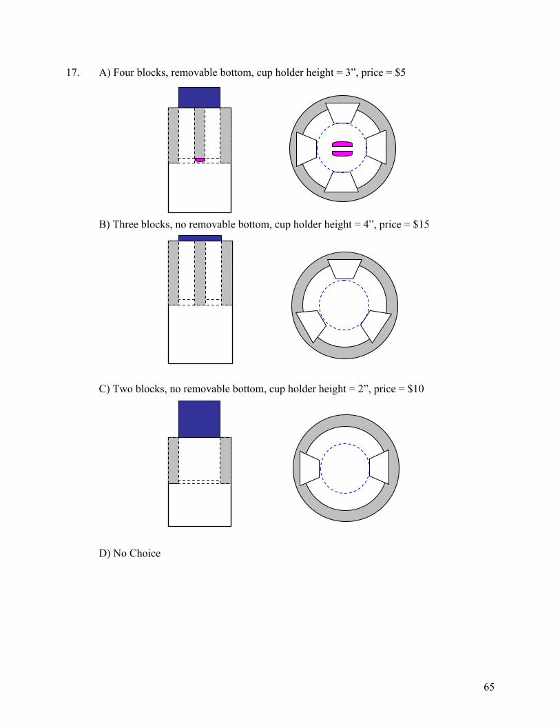
65
17. A) Four blocks, removable bottom, cup holder height = 3”, price = $5 B) Three blocks, no removable bottom, cup holder height = 4”, price = $15 C) Two blocks, no removable bottom, cup holder height = 2”, price = $10 D) No Choice

66
18. A) Four blocks, removable bottom, cup holder height = 3”, price = $5 B) Three blocks, no removable bottom, cup holder height = 2”, price = $10 C) Two blocks, removable bottom, cup holder height = 4”, price = $15 D) No Choice

67
19. A) Four blocks, no removable bottom, cup holder height = 3”, price = $10 B) Three blocks, removable bottom, cup holder height = 2”, price = $15 C) Two blocks, removable bottom, cup holder height = 4”, price = $5 D) No Choice

68
20. A) Four blocks, no removable bottom, cup holder height = 4”, price = $15 B) Zero blocks, removable bottom, cup holder height = 3”, price = $5 C) Two blocks, no removable bottom, cup holder height = 2”, price = $10 D) No Choice

69
21. A) Four blocks, no removable bottom, cup holder height = 3”, price = $10 B) Three blocks, removable bottom, cup holder height = 2”, price = $5 C) Two blocks, removable bottom, cup holder height = 4”, price = $15 D) No Choice

70
22. A) Two blocks, no removable bottom, cup holder height = 4”, price = $15 B) Four blocks, removable bottom, cup holder height = 2”, price = $10 C) Three blocks, removable bottom, cup holder height = 3”, price = $5 D) No Choice

71
23. A) Four blocks, removable bottom, cup holder height = 2”, price = $5 B) Two blocks, no removable bottom, cup holder height = 3”, price = $10 C) Zero blocks, removable bottom, cup holder height = 4”, price = $15 D) No Choice

72
24. A) Three blocks, no removable bottom, cup holder height = 4”, price = $15 B) Four blocks, removable bottom, cup holder height = 3”, price = $5 C) Zero blocks, removable bottom, cup holder height = 2”, price = $10 D) No Choice

73
Appendix I: Model Comparison
ENGINEERING ECONOMICS MARKETINGengineering our design optimal for profit parametric study 1 optimal for profit parametric study 2 optimal for profitoptimized (Hc=4",P=$10) (#blocks = 3) (#blocks = 3) (#blocks = 4) (#blocks = 4)
profit n/a 7,524,336$ 7,568,004$ 6,317,896$ 9,317,002$ 6,385,914$ 9,455,814$ revenue n/a 9,335,570$ 9,262,175$ 7,865,870$ 10,685,100$ 7,948,730$ 10,841,955$
cost n/a 1,811,234$ 1,694,170$ 1,547,974$ 1,368,098$ 1,562,816$ 1,386,141$ price n/a $10.00 $10.67 $10.00 $15.00 $10.00 $15.00
#blocks 3 3 3 3 3 4 4rem. bottom 1 1 1 1 1 1 1
height 4.00 4.00 4.00 4.00 3.19 4.00 3.19demand n/a 933,557 868,204 786,587 712,340 794,873 722,797

74
Appendix J: Business Plan
Business Opportunity
Objectives The Driver’s Dream cup holder will be produced and manufactured by JCI or a comparable company. The main objective is for this cup holder to become the cup holder of choice in midsize vehicles. Over the next three years it is hoped that the Driver’s Dream cup holder will be placed in 50% of all new midsize vehicles purchased. The product line will also be expanded to produce a model that can be used in various other sized vehicles.
Product Description The Driver’s Dream cup holder is an adjustable cup holder for the driver of a midsize vehicle. It will automatically adjust to a variety of containers; while not being intrusive to the driver controls or to the driver. The Driver’s Dream has the following advantages over an ordinary cup holder:
• Ergonomic • Easily adjustable to various container sizes • Easy to use and clean
The Driver’s Dream line will be expanded to include various additions for different consumers. The line will expand to include a cup holder that will fit in larger variety of cars. It will also be expanded to include options for a larger variety of cup sizes if needed. A line will also be included that incorporates a heating/cooling element to the cup holder. This will allow beverages to be kept at a desired temperature.
Market Analysis The market the Driver’s Dream is currently targeting is the owners of midsize cars; this market is divided as shown in Figure 1.
GM29%
Ford15%Toyota
21%
Honda20%
Nissan10%
Chrysler5%
Figure 1: Market size of automakers in midsize vehicles
The type of driver of midsize cars that is being targeted are those drivers who spend a lot of time driving in their car by themselves. The driver would want to accommodate many different types of cups and water bottles.

75
Capital and Personal Resources The new product line initial start-up costs are $1,050,000. This initial investment is to pay for the costs of development, design, manufacturing engineering, manufacturing equipment, and initial material costs. JCI will be able to fund this new project with revenues from other projects. The production of the Driver’s Dream cup holder will be done at an existing JCI facility that has extra floor space.
Financial Data
Capital Equipment and Suppy List The Driver’s dream will require 3 injection molding machines and dies, assembly line equipment, ABS plastic, and springs. The cost of supplies per part is a total of $0.41. The cost of ABS per cup holder is $0.31 and the springs cost $0.10.
Break-Even Analysis The number of cup holders that need to be made to break-even is approximately 720,000 as shown in Table 1 and Figure 2. This amount of cup holders will be produced before the end of year one in order to keep up with demand.
Figure 2: Break-Even Analysis
-$10,000,000.00
-$5,000,000.00
$0.00
$5,000,000.00
$10,000,000.00
$15,000,000.00
$20,000,000.00
0 500000 1000000 1500000 2000000 2500000 3000000
Number Produced
Break-even Point
Table 1: Break-Even Analysis Break-even Analysis Break-even Amount 720,000 Assumptions: Average Per-Unit Revenue $10.00Average Per-Unit Variable Cost $2.00Total fixed costs 3 years $5,965,200.00

76
Pro-forma Income and Cost Table 2 shows the profit & loss statement for Driver’s Dream cup holder for the next three years. Along with what the companies net present value is for the three years.
Table 2: Profit & Loss Statement 3 years Year Initial 2005 2006 2007Demand 712,000 726,000 741,000Sales $7,120,000.00 $7,260,000.00 $7,410,000.00 Material costs of goods $356,000.00 $363,000.00 $370,500.00 Gross margin $6,764,000.00 $6,897,000.00 $7,039,500.00 Expenses: Payroll $1,444,200.00 $1,494,000.00 $1,555,000.00 Sales and marketing $100,000.00 $100,000.00 $100,000.00 Depreciation $8,000.00 $8,000.00 $8,000.00 Equipment (Initial) $1,050,000.00 Equipment upkeep $19,000.00 $19,000.00 $19,000.00 Utilities $12,000.00 $14,000.00 $15,000.00 Total Op Costs $1,050,000.00 $1,583,200.00 $1,635,000.00 $1,697,000.00 Profit before tax $5,180,800.00 $5,262,000.00 $5,342,500.00 TAX $1,554,240.00 $1,578,600.00 $1,602,750.00 Net profit ($1,050,000.00) $3,626,560.00 $3,683,400.00 $3,739,750.00 NPV $8,100,734.49
The assumptions made for calculating the cash flows for the next three years are shown in Table 3. It was also assumed that JCI or a similar company would have enough floor space for this new project and that they also would be able to fund the initial investments for the project. The discount rate was determined using the Capital asset pricing model, using a risk free rate (the rate of a 15 yr bond) of 4.08%, a market rate of 10% and a Beta from JCI of 0.765.
Table 3: Rate Assumptions for Cash Flows Tax Rate 30% Discount Rate 8.61% Rate of demand increase 2%
Supporting Documents
Patents A patent search of United States Patents and Trademark website of patents granted after 1976. The search was done by searching “cup holder.” The search presented 1411 items of which most were not applicable; the applicable patents are shown in Table 4. A table of the applicable cup holder patents is shown in Table 1 below. These cup holders did not have the range of adjustability that is needed for car owners, especially those that are included as part of the center counsel.

77
Table 4: Summary of “Cup Holder” Patent Search Patent # Description D493,072 Adjustable cup holder 6,776,381 Cup holder D497,779 Cup holder 6,799,705 Cup holder closure and release apparatus 6,796,591 Glove compartment and cup holder device for
automobile 6,732,894 Vehicle cup holder arm assembly 6,712,325 Cup holder for automobile 6,705,580 Cup holder for a motor vehicle 6,702,243 Cup holder for a vehicle 6,702,241 Cup holder 6,698,703 Compartment mounted automotive beverage
container holder 6,670,583 Heated cup holder system 6,644,526 Motor vehicle central console 6,637,709 Self-adjustable cup holders 6,637,617 Inflatable vehicle cup holder 5,573,214 Window Cup holder
Technical Analysis & Benchmarking Technical analyses that were performed are shown in Appendix F. Benchmarking was done by looking at existing cup holders in midsize vehicles and by making various measurements of a Pontiac Grand Am to determine if the Driver’s Dream would fit into the existing center console. These measurements were of the current cup holder area, this area could be increased in order to fit the Driver’s Dream. The important measurements are shown in Table 5.
Table 5: Grand Am Center Console Dimensions Total Depth of Console 8.01 in Length 6.59 in Width 4.12 in