driver-engineer handbook 2004 - ningapi.ning.com/.../driverengineerhandbook2004.pdf ·...
TRANSCRIPT

Page 1 6/24/2004
Driver-Engineer Handbook 2004
The driver-engineer is responsible for the safe transportation of firefighters, apparatus, and equipment to and from the scene of an emergency. Once on the scene, the driver-engineer must be capable of operating the apparatus properly and safely to accomplish specific goals. The driver-engineer must also ensure that the apparatus and equipment carried on the apparatus are maintained in a ready condition at all times. Qualified driver-engineers, thoroughly trained with an ongoing program of practice, study and drill are required to fulfill this responsibility. The life of the firefighter and the civilian is in the hands of the driver-engineer. To fulfill this responsibility the driver-engineer must have the knowledge and skill to safely operate the apparatus. This packet has been compiled to assist you with the proper operation and maintenance of your apparatus. The information contained in this packet is general in nature and applies to most apparatus in service in the Miami Fire Department. Additional specific information on your individual apparatus is available in the apparatus manuals kept in each station. The Driver-Engineer Instructor is available to assist you in any way possible through schools, drills, and specialized training to meet your individual needs. The job of a driver-engineer is not an easy one, but with the proper training and drill it can be one of the most rewarding jobs on the fire department.
Page 2 6/24/2004
TABLE OF CONTENTS
1. Diesel Engine Information 5 Operation of the Turbocharger Fuel System Lubrication System Cooling System Starting the Engine Stopping the Engine Engine Gauges and Warning Devices 2. Automatic Transmission Information 12 Transmission Temperature Oil Check Procedure 3. Air Brake Information 14 Air Compressor Air Compressor Governor Air Storage Tank Tanks Air Tank Drains Safety Valve The Brake Pedal Supply Pressure Gauges Low Air Pressure Warning Front Brake Limiting Valve Spring Brakes Parking Brake Controls Dual Parking Control Valves Dual Air Brake Systems 4. Using Air Brakes 17 Normal Stops Emergency Stops Stopping Distance Braking Low Air Pressure Warning Parking Brakes 5. Pump Information 20 Centrifugal Pumps Priming Pumps Two Stage Pumps Single Stage Pumps Typical Pump Installation

Page 3 6/24/2004
6. Pump Panel Information 25 Intake Gauge Discharge Gauge Pump Connections Pump Overheating Engine Overheating Relief Valve Information Operating Instructions for Setting Relief Valve Pressure Governor Operation 7. Apparatus Inspection 31 Daily Apparatus Check Weekly Apparatus Check Monthly Apparatus Check 8. Additional Information for Driver-Engineers 34 Battery Chargers Underwriters’ Pump Service Test Pump Procedures for Allison Transmissions Operation of L.T.I. Winches Foam Operations Drafting Operations Limits from Mains 5 Inch Hose 9. Aerial Operations 46 Types of Aerials Positioning of Aerial Apparatus Aerial Setup Sequence of Operations Aerial Safety 10. Emergency Vehicle Operation 49 Vehicle Riding Policy Florida State Uniform Traffic Control Law Passing School Buses Following other Apparatus Standardized MFD Horn/Hand signals Vehicle Shut Down Procedures Alpha Responses
Page 4 6/24/2004
11. Fire Service Hydraulics 61 Six Principles of Fluid Pressure Five Types of Pressure Friction Loss Maximum Efficient Flow Standard Starting Engine Pressure Driver-Engineer Rule of Thumb Supplement How to Figure Engine Pressure Calculating friction Loss Hose Units Total Friction Loss Nozzle Pressure Appliance Pressure Back Pressure Standpipe or Sprinkler System Engine Pressure Siamese Lines Wyed Lines Pumping Supply Lines Pumping in Relay Pumping to Aerials Pumping 5 Inch Hose Sample Hydraulic Problems Answers to Hydraulic Problems 12. Driver-Engineer Checkout Procedure 83 O.P.M. Study References Driver-Engineer Checkout Form Driving Score Sheet Serpentine Course Straight-Line Exercise Offset Alley or Opposite Alley Alley Doc 13. Reserve Driver-Engineer Course Requirements 90 14. CDL Brake Test 95 15. Supplemental Hydraulics Information 97 Fluid Pressure Illustrations Water Flow Illustrations Fundamental Rules of Friction Loss Illustrations Ways to Reduce Friction Loss Guidelines for Maximum Efficient Flow Standard Starting Engine Pressures Rule Of Hand Formulas

Page 5 6/24/2004
DIESEL ENGINE INFORMATION The major difference between diesels and gasoline engines is in the ignition process. The gasoline engine mixes air and fuel in the carburetor and relies on an electrical spark to ignite the mixture after it is compressed in the cylinder. The diesel engine has no carburetor or electrical ignition system. Designed with much-higher compression ratios, the diesel engine relies on the heat of compression to ignite the fuel. When the air is highly compressed in the cylinder it heats up to ignition temperature, at that time fuel is injected. Ignition takes place and the expansion of hot gasses drives the piston down on the power stroke.

Page 6 6/24/2004
DIESEL ENGINE INFORMATION Cont. A diesel engine converts a higher percentage of the potential energy in a gallon of fuel into useful work. Diesel fuel usually costs less per gallon and does more work per gallon. In some applications, 11 gallons of gasoline are necessary to do the work accomplished by 6 gallons of diesel fuel. Diesel engines can be two-cycle or four cycle design. The following illustration shows the difference between a two-cycle and a four cycle diesel engine.
Four-Cycle: The piston moves down and draws in fresh air. The intake valves close and the piston moves up, compressing the air. Fuel is injected and ignites, driving the piston down on the power stroke. The piston moves up and pushes the burned gases out the open exhaust valves. Two crankshaft revolutions are needed to complete one power cycle.

Page 7 6/24/2004
Detroit Diesel Two-Cycle: Fresh air enters the cylinder under pressure, from an efficient blower. Simultaneously, this air forces exhaust gases out the open exhaust valves. The exhaust valves close and the upward-moving piston compresses the air to ignition temperature. Fuel is injected, ignites, and drives the piston down on the power stroke. This completes the power cycle in only one revolution of the crankshaft. Operation of the Turbocharger: The turbine wheel of the turbocharger is driven by engine exhaust gases. The compressor wheel is shaft driven by the turbine. The compressor pumps air into the engine to increase the amount of air available for combustion. The results are improvements in engine power output and altitude performance. The disadvantage of a turbocharger is high internal temperatures. The turbocharger must cool down prior to shutdown. Manufactures recommend a 5-minute cool down period at idle prior to shutdown.
Turbocharger

Page 8 6/24/2004
Fuel System: Fuel is drawn from the supply tank through the fuel strainer. The strainer separates water from the fuel. The clear bowl at the bottom of the strainer should be checked daily for water. If water is present call the shop. After leaving the strainer the fuel travels to the fuel pump. The pump is an engine driven gear-type pump. Leaving the pump under pressure, the fuel is forced through the fuel filter and into the inlet fuel manifold in the cylinder head, then through fuel pipes into the inlet side of each fuel injector. Surplus fuel returns from the outlet side of the injectors to the fuel return manifold and then back to the supply tank.
Lubrication System: The engine lubrication system is pressure regulated. The lubricating oil is filtered by a full-flow filter and cooled by a block-mounted oil cooler. The rotating parts of the turbocharger are pressure lubricated from the engine lubrication system. Check the oil level with the engine stopped and the vehicle on level ground. If the engine has just been shut off, allow at least 5 minutes for the oil to drain back to the oil pan. Maintain the oil level between the FULL and LOW MARKS ON THE DIPSTICK. Overfilling will cause the oil to be churned by the crankshaft throws causing foaming or aeration of the oil. Operation below the LOW mark will expose the pump pickup causing aeration and/or loss of pressure. A fluttering oil pressure gauge indicates a low oil level. The proper oil for apparatus is as follows:
Page 9 6/24/2004
Detroit Diesel:
Series 40 & 60 6V71 (Young Quints) 8V71 (1983 Pierce Engines)
15W-40
SAE 40 OR XHD 40SAE 40 or XHD 40
Cummins Diesel:
Freightliner (Rescues)
15W-40
International Diesel:
International (Rescues)
15W-40
Ford Diesel:
Ford rescue CD30 or CE30
Cooling System: The cooling system consists of a circulation pump, thermostat for regulating coolant temperature, oil cooler, radiator and belt-driven fan. To check for proper level of coolant, remove the cap when the engine is cool, look into the radiator and visualize the fluid. The fluid should be approximately 1-2 inches below the cp. Some radiators are equipped with a sight glass on the side to check for fluid without removing the cap, verify that fluid is in the sight glass. Starting the Engine: Check the following items before starting the engine: 1 Check floor for fluids 2 Be sure oil level is at or close to full mark 3 Check fuel supply 4 Check radiator fluid level through cap or sight glass To start the engine: 1 To start the engine: 2 Verify parking brake is applied. 3 Place transmission shift lever in the NEUTRAL position 4 Turn battery switch to BOTH. 5 Turn ignition switch ON. 6 Press both START buttons.

Page 10 6/24/2004
NOTE: If the engine does not start after 30 seconds of cranking, allow the starter motor to cool for at least 2 minutes before trying again for non emergency situations. NOTE: Pumping the accelerator before or during cranking will not aid in starting. NOTE: When the engine starts, allow it to idle. If the oil pressure does not register within 10-15 seconds of starting, stop the engine and contact the shop. Stopping the Engine: With the vehicle stopped, apply the parking brake and place the transmission shift lever in NEUTRAL. Press the ENGINE STOP button or pull the T handle. This shuts off the fuel supply to the engine. The EMERGENCY STOP control is used only when the engine does not respond to the normal ENGINE STOP control usually on an uncontrolled fuel source. When actuated the EMERGENCY STOP valve closes cutting off the engines air supply. Without air the engine cannot run. If an emergency shutdown is necessary, the engine must not be started again until the atmosphere near the air intake clears of the combustible mixture. Then the valve located in the air inlet must be reset by hand from outside the cab and the EMERGENCY STOP control returned to the RUN position before the engine can be restarted. Apparatus equipped with a turbo charger are not equipped with an EMERGENCY STOP control. NOTE: During prolonged idling rev the engine to 1,000 RPM. This keeps the injectors from fowling and operates the electrical system at optimum performance. Shut off excessive lights when not needed. Engine Gauges and Warning Devices: Right after the engine starts and at frequent intervals during operation, check the instrument panel gauges and warning devices to be sure the engine and apparatus are operating normally. The following gauges and warning devices shall be checked: Oil Pressure Gauge: During normal driving periods, the oil pressure will read between 40 and 60 psi. At idle speed a lower oil pressure is normal. If no oil pressure is indicated, the engine should be shut down immediately. Coolant Temperature Gage: After the engine is thoroughly warmed up, check the coolant temperature.

Page 11 6/24/2004
Detroit Diesel 170 to 195 degrees F Cummins 180 to 200 degrees F International 180 to 200 degrees F Ford Diesel 170 to 195 degrees F Dual Warning Indicator: The indicator is a light and buzzer located on the dash; it indicates high engine temperature or low oil pressure. Fuel Gauge: Indicates the level of fuel in the fuel tank. Racor Gauge: Indicates fuel filter contamination or restriction. LAK 1: a small black box with a LED light on the front. When activated it beeps and lights up. This indicates water in the fuel bowl separator. Air Restriction Indicator: A vacuum gauge that indicates an obstruction in the air intake system or filter. Volt Meter: Indicates the condition of the batteries and if the charging system is operating properly. Amp Meter: Indicates the rate of charge or discharge. Odometer: Indicates the miles the apparatus has traveled. Speedometer: Indicates the speed in M.P.H. Tachometer: Indicates the R.P.M. of the engine. Transmission Temperature Gauge: Indicates the temperature of the transmission. Normal transmission temperature is 160-200 degrees. Air Pressure Gauge: Indicates air pressure in the air brake system. Normal air pressure when driving is 100-120 psi. Auxiliary Braking Systems NOTE: All classes of brake retarders must be turned off during wet weather. Telma Brake Retarder: Uses a magnetic field to place a drag on the drive shaft. This in turn assists the brakes during braking operations. As a result the brakes do not overheat as quickly preventing brake fade.
Page 12 6/24/2004
NOTE: During operation if you find a Telma light does not go on: you may experience early brake fade; notify the shop. If a light stays on you may do permanent damage to Telma. JAKE BRAKE/EXAUST RETARDER/X-TARDER: Uses exhaust gasses to slow the engine RPM/drive train assisting brakes. When your foot is not on the accelerator the Jake Brake engages, making it difficult to coast through intersections TRANSMISSION RETARDER/TRANSTARDER: Diverts transmission fluid within the transmission placing drag on the drive train. Be aware the transmission temp will rise and may overheat during prolonged usage.
AUTOMATIC TRANSMISSIONS
Transmission Temperature: The transmission fluid temperature is indicated by a gauge specifically designed for this purpose. Extended operations at low vehicle speeds with the engine at full throttle can cause excessively high fluid temperatures in the transmission. These temperatures may tend to overheat the engine cooling system as well as cause possible transmission damage. Normal transmission operating temperature is 160-200 degrees F. If excessive temperature is indicated by the transmission fluid temperature gauge, stop the vehicle and shift to neutral. Accelerate the engine to 1200-1500 RPM and allow the temperature to return to normal (two or three minutes) before resuming operation. Importance of proper fluid Level: Since the transmission fluid cools, lubricates, and transmits power, it is important that the proper level be maintained at all times. If the level is to low, the converter and clutches will not receive an adequate supply of fluid. This can result in poor performance or transmission failure. If the level is too high, the fluid will aerate, causing the transmission to overheat. Check the fluid level on a daily basis.

Page 13 6/24/2004
Transmission Fluid Check Procedure: Always clean around the end of the fill tube (as in all fluid reservoirs) before removing the dipstick. Dirt or foreign matter must not be permitted to enter the system. Check for an abnormal fluid level or milky appearance due to coolant leaking into transmission fluid. Check the fluid level by one of the following procedures: Hot Check:
1. Operate the transmission in a drive range until operating temperature of 160-200 degrees F. is reached.
2. Shift through all drive ranges to fill the clutches and fluid passages.
3. Park the vehicle on a level spot, shift to neutral and apply the parking brake. Let the engine run at idle speed.
4. Wipe the dipstick clean and check the fluid level. The safe operating level is any level within the HOT RUN band on the dipstick.
Cold Check:
1. A cold fluid check may be made when the sump temperature is 60-120 degrees F.
2. Run the engine for at least 1 minute to clear the fluid system of air.
3. With the engine running at idle, wipe the dipstick clean and check the fluid level. Any level within the COLD RUN band is safe for operating the vehicle.
4. Follow up with a hot check. NOTE: If you experience any of the following: overheating, shifting feels odd, unusual sounds, transmission shifts up or downshifts at irregular intervals, fluid leaks from the transmission, or low fluid level, contract the shop.
Page 14 6/24/2004
AIR BRAKES The following information is taken from the excerpts from the “Commercial Driver License” Manual. Air brakes use compressed air to make the brakes work. You can apply all the braking force you need to each of the wheels of a heavy vehicle, even units pulling 2 or 3 trailers. Air brakes are a safe way of stopping large vehicles if the brakes are well maintained and used right. However, you must know more about air brakes than you need to know with the simpler brake systems used on light vehicles. Air brakes systems are three braking systems combined: the service brake system, the parking brake system, and the emergency brake system.
The service brake system applies and releases the brakes when you use the brake pedal during normal driving. The parking brake system applies and releases the parking brakes when you use the parking brake control. The emergency brake system uses parts of the service and parking brake systems to stop the vehicle in the event of a brake system failure.
There are many parts to an air brake system. You should know about the parts discussed here. Air Compressor: The air compressor pumps air into the air storage tanks (reservoirs). The air compressor is connected to the engine through gears or a V-belt. Air Compressor Governor: The governor controls when the air compressor will pump air into the air storage tanks. When air tank pressure rises to the “cut-out” level (around 120 pounds per square inch, or “PSI”), the governor stops the compressor from pumping air. When the tank pressure falls to the “cut-in” pressure (around 100 PSI) the governor allows the compressor to start pumping again.

Page 15 6/24/2004
Air Tank Drains: Compressed air usually has some water and some compressor oil in it which is bad for the air brake system. Therefore each air tank is equipped with a drain valve in the bottom. There are two types:
Manually operated: By turning a quarter turn. You must drain the tanks yourself at the beginning of each day of driving. Automatic: The water and oil is automatically expelled. While the engine is running, an air discharge sound will be heard every few minutes.
Safety Valve: A safety relief valve is installed in the first tank the compressor charges. The safety valve protects the tank and the rest of the system from too much pressure. The valve is usually set to dump at 150 PSI.
The Brake Pedal: You put on the brakes by pushing down the brake pedal. Pushing the pedal down harder applies more air pressure. Letting up on the brake pedal reduces the air pressure and releases the brakes. Releasing the brakes lets some compressed air go out of the system, so the air pressure in the tanks is reduced. The pressure must be made up by the air compressor. When you depress the brake pedal, two forces push back against your foot. One force comes from a spring on the brake pedal itself. The second force comes from the air pressure going to the brakes. These two forces allow you to feel how much air pressure is being applied to the brakes. Note: Pressing and releasing the pedal unnecessarily can let air out faster than the compressor can replace it. If the pressure gets too low, the brakes will not work. Supply Pressure Gauges: All air-braked vehicles have a pressure gauge connected to the air tank. If the vehicle has a dual air brake system, there will be a gauge for each half of the system. (Or a single gauge with two needles). Dual systems will be discussed later. These gauges show how much pressure is in the air tanks.

Page 16 6/24/2004
Low Air Pressure Warning: A low air pressure-warning signal is required on vehicles with air brakes. A visible warning signal must activate before the air pressure in the tanks falls below 80-85 PSI. The warning is usually a red light. A buzzer may also activate. Spring Brakes: All trucks, truck tractors, and buses must be equipped with emergency brakes and parking brakes. They must be engaged by mechanical force (because air pressure can eventually leak away). Spring brakes are usually used to meet these needs. When driving, the spring brakes are kept retracted by air pressure. If the air pressure is removed, the springs automatically activate. A parking brake control in the cab allows the driver to release the air pressure which is retaining the spring brakes. This applies the spring brakes. A leak in the air brake system which causes all the air pressure to be lost will also cause the spring brakes to be applied. Spring brakes will engage when the air pressure drops to a range of 20 to 45 PSI. Do not wait for the brakes to engage automatically. When the low air pressure warning light and buzzer indicate low pressure, bring the vehicle to a safe stop off the roadway. When the spring brakes automatically apply you will not be able to move the apparatus. Parking Brake Controls: The parking brakes are applied by a, push-pull control knob. The knob is pulled to apply the parking brakes, and pushed to release them. Spring Brake Release: Some vehicles have a separate air tank, which can be used to release the spring brakes. This is used to move the vehicle from the roadway after the emergency brake has been activated. You must depress and hold the control knob to allow air from a separate air tank to momentarily releases the spring brakes. This allows the apparatus to move a short distance. When you release the knob, the spring brakes re-engage. The spring brakes will remain released until the reserve tank is depleted of air pressure. Plan the move carefully to insure you have adequate time to complete the move before the Spring Brakes re-engage.

Page 17 6/24/2004
Dual Air Brake Systems: Most newer heavy-duty vehicles use dual air brake systems for safety. A dual air brake system has two separate air brake systems, which use a single set of brake controls. Each system has its own air tanks, hoses, lines, etc. One system typically operates the regular brakes on the rear axle or axles. The other system operates the regular brakes on the front axle. The first system is called the “primary” system. The other is called the “secondary” system. Before driving a vehicle with a dual air system, allow time for the air compressor to build up a MINIMUM of 100-PSI pressure in both the primary and secondary systems. You need at least 60 PSI to release the spring locks. Watch the primary and secondary air pressure gauges (or needles, if the system has two needles in one gauge). The warning light and buzzer should shut off when air pressure in both systems rises to 80-85 PSI. The warning light and buzzer should come on before the air pressure drops below 80-85 PSI in either system. If this happens while driving you should stop immediately and safely park the vehicle. If one air system is very low on pressure, either the front or the rear brakes will not be operating fully. This means it will take you longer to stop. Bring the vehicle to a safe stop, and have the air brake system fixed.
USING AIR BRAKES Normal Stops: Push the brake pedal down. Control the pressure so the vehicle comes to a smooth, safe stop
Emergency Stops: You should brake so you can steer and so your vehicle stays in a straight line. Use one of the following two methods. Threshold braking: FOR DRY ROAD CONDITIONS This method is also called “squeeze” braking. Slowly increase braking pressure to prevent wheels from skidding. Stab braking. FOR WET ROAD CONDITIONS without ABS Repeatedly pressing on the brake pedal and releasing it in rapid succession so as to not lose steering ability during slippery conditions. It can take up to one second for the wheels to start rolling after you release the brakes. ABS BRAKING for ANY ROAD CONDITIONSSS Stomp/Stand and Stay

Page 18 6/24/2004
TELMA BRAKE RETARDER
ABS INTERFACE
The Telma ABS interface module was developed in cooperation with ABS manufacturers to provide functions that allow the anti- lock braking system (ABS) to automatically control the Telma during critical wheel slip conditions and in case of ABS malfunction. This interface with the ABS allows automatic control of the Telma under all road conditions eliminating the need for a manual switch to turn off the retarder during slippery conditions. The ABS control module (ECU) of most medium and heavy-duty vehicles provide specific outputs for connection to the Telma to allow the following functions.
Control function During critical wheel slip conditions the ABS instantaneously and automatically cuts out the Telma and re-enables the system when normal road conditions return. The Telma ABS interface monitors the gradual return of the braking torque in relation to road adhesion conditions.
Safety Function If the ABS self-check detects a fault and illuminates the dashboard warning light the Telma is disabled until the fault is corrected and the ABS warning light is turned off. The Telma ABS interface also incorporates a low speed shut off function using the vehicle speed signal to automatically the Telma system when speed slows to about 2 mph. The Telma is no longer effective below this speed. NOTE: If the brakes are wet from driving through deep water, depress the brakes lightly while driving to heat and dry them.

Page 19 6/24/2004
Stopping Distance: With air brakes there is an added delay: the time required for the brakes to work after the brake pedal is pushed. With hydraulic brakes (used on cars and light/medium Trucks), the brakes work instantly. However, with air brakes, it takes a little time (one half second or more) for the air to flow through the lines to the brakes. Thus, the total stopping distance for vehicle with air brake systems is made up of four different factors.
Perception Distance + Reaction Distance + Brake Lag Distance + =
Effective Braking Distance Total Stopping Distance
The air brake lag distance at 55 M.P.H. on dry pavement adds about 32 feet. So at 55 M.P.H. for an average driver under good traction and brake conditions, the total stopping distance is over 300 feet. This is longer than a football field. Braking: When you use the brakes, they get hot. Brakes can take a lot of heat. However, brakes can stop working if there is too much heat build-up.
A. Brake fade: Occurs when the glue holding the brake pad fibers together gasses out acting as a lubricant on the rotor. This takes place during extended brake use without sufficient cooling time in between braking sessions. This condition will significantly reduce braking ability, which will resolve itself once the rotors and pads cool sufficiently. B. Parking brake fade: is caused by driving with the parking brake engaged (engine power may overcome parking brake friction). This will cause the parking brake to overheat rendering them ineffective when needed. If you suspect the vehicle was driven with the Parking brake engaged, disengage the parking brake. (DON’T FORGET TO USE WHEEL CHOCKS!) C. Brake Glaze: Permanent condition caused by the brakes overheating on numerous occasions.
Low Air Pressure Warning: If the low air pressure warning comes on, stop and safely park your vehicle as soon as

Page 20 6/24/2004
possible. There might be an air leak in the system. Controlled braking is possible only while enough air remains in the air tanks. The spring brakes will come on when the air pressure drops into the range 20 to 45 PSI. A heavily loaded vehicle will take a long distance to stop, because the spring brakes do not work on all axles. Lightly loaded vehicles or vehicles on slippery roads may skid out of control when the spring brakes come on. It is much safer to stop while there is enough air in the tanks to use the foot brake. Parking Brakes: Any time you park use the parking brakes. Pull the parking brake control knob to apply the parking brakes, push it in to release them. The control is a yellow knob, labeled “parking brakes”.
Pump Information Centrifugal Pumps: The most common type of pump in use in the fire service today is the centrifugal pump. The centrifugal pump is classified as a nonpositive displacement pump since it does not pump a definite amount of water with each revolution. The operation of a centrifugal pump is based on the principle that a rapidly revolving disk tends to throw water introduced at its center toward the outer edge of the disk. The faster the disk is turned, the more velocity the water will have. The centrifugal pump consists of three parts; the eye, impeller, and the volute. Water enters the pump through the eye of the impeller. After entering the eye it moves through the impeller and increases in velocity with the speed of the impeller. The impeller is mounted off-center in the casing and increases in area as it nears the discharge outlet. This casing is known as the volute. (Figure 1) NOTE: Centrifugal pumps will not operate properly when AIR is introduced to the pump. The pump will also be adversely affected if DEBRIS enters the pump impeller. If the pump is allowed to OVERHEAT it will cavitate further adversely affecting the pump seals, gaskets, etc.
Page 21 6/24/2004
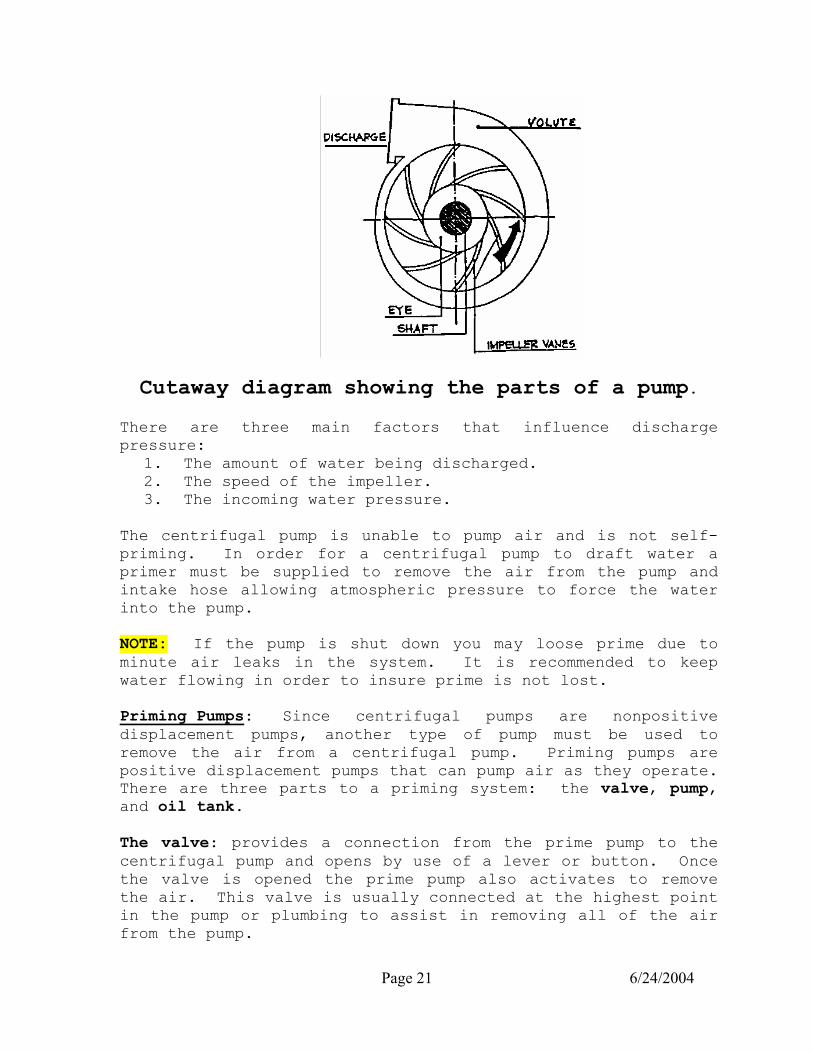
Cutaway diagram showing the parts of a pump.
There are three main factors that influence discharge pressure:
1. The amount of water being discharged. 2. The speed of the impeller. 3. The incoming water pressure.
The centrifugal pump is unable to pump air and is not self-priming. In order for a centrifugal pump to draft water a primer must be supplied to remove the air from the pump and intake hose allowing atmospheric pressure to force the water into the pump. NOTE: If the pump is shut down you may loose prime due to minute air leaks in the system. It is recommended to keep water flowing in order to insure prime is not lost. Priming Pumps: Since centrifugal pumps are nonpositive displacement pumps, another type of pump must be used to remove the air from a centrifugal pump. Priming pumps are positive displacement pumps that can pump air as they operate. There are three parts to a priming system: the valve, pump, and oil tank. The valve: provides a connection from the prime pump to the centrifugal pump and opens by use of a lever or button. Once the valve is opened the prime pump also activates to remove the air. This valve is usually connected at the highest point in the pump or plumbing to assist in removing all of the air from the pump.

Page 22 6/24/2004
Priming pumps: They are usually rotary gear or rotary vane driven by an electric motor. The electric motor allows flexibility in mounting the pump to the chassis. The electric motor can only be operated for a short period of time before the motor overheats. Therefore, the maximum amount of time allowed for drafting or priming is 30 seconds (45 seconds for 1500 GPM pumps) to prevent overheating the prime motor. Most primers use an oil supply (“30 weight” for 1983 Pierce and Young apparatus, “Prime Safe” for the newer pumps). The oil serves two purposes. 1. Improves efficiency As the pump wears, clearance between the gears and the casing increases, and the pump loses efficiency. A thin film of oil is drawn into the pump and seals the gaps between the gears and the casing. The oil improves the efficiency of the primer. 2. Anticorrosive The oil also acts as a preservative and minimizes deterioration of the metal parts by inhibiting corrosion when the pump is not in use. There is a vent in the oil line from the reservoir to the priming pump. Since the tank is frequently mounted higher than the priming pump, a siphon action would drain the tank after the primer has been used. This vent breaks the siphon. It must be large enough to serve the purpose, but small enough to allow the priming pump to draft the oil out of the tank when the primer is in use. Make sure that the vent hole is not plugged to prevent siphoning all of the prime oil out of the tank.
Page 23 6/24/2004
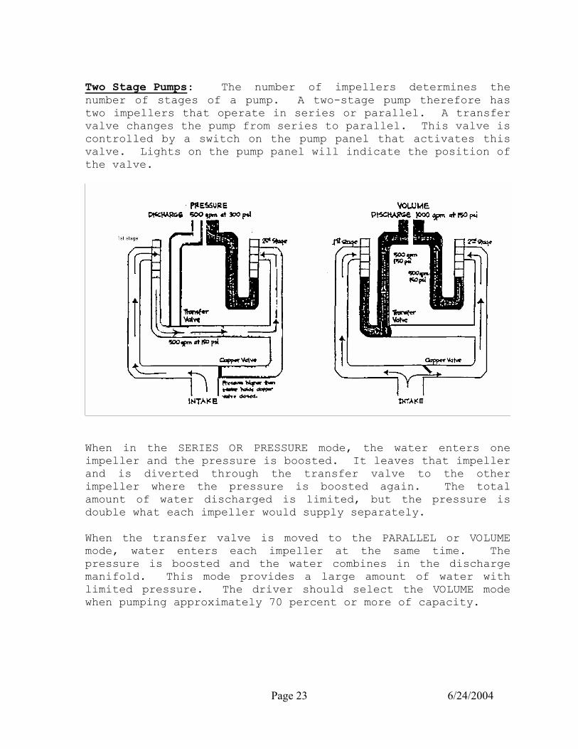
Two Stage Pumps: The number of impellers determines the number of stages of a pump. A two-stage pump therefore has two impellers that operate in series or parallel. A transfer valve changes the pump from series to parallel. This valve is controlled by a switch on the pump panel that activates this valve. Lights on the pump panel will indicate the position of the valve.
When in the SERIES OR PRESSURE mode, the water enters one impeller and the pressure is boosted. It leaves that impeller and is diverted through the transfer valve to the other impeller where the pressure is boosted again. The total amount of water discharged is limited, but the pressure is double what each impeller would supply separately. When the transfer valve is moved to the PARALLEL or VOLUME mode, water enters each impeller at the same time. The pressure is boosted and the water combines in the discharge manifold. This mode provides a large amount of water with limited pressure. The driver should select the VOLUME mode when pumping approximately 70 percent or more of capacity.

Page 24 6/24/2004
Single Stage Pumps: The most common type of centrifugal pump is the single stage pump. As the name implies, the stage pump has only one stage and thus only one impeller. ADVANTAGES 1. Simplicity of operation. 2. No transfer valve to malfunction. 3. No confusion on when to switch over. 4. The throttle controls performance. 5. Cost. DISADVANTAGES 1. Higher RPMs required to achieve high pressures. 2. Some realistic pressures and volumes cannot be reached.
The single stage pump is rapidly replacing the two-stage pump for many of the above reasons. The easiest way to determine if the pump is a single stage or a two-stage pump is to look for a transfer valve switch on the pump panel. If there is not a transfer valve, the pump is a single stage. Typical Pump Installation: Pumps can be mounted to the apparatus in many ways and many locations, the most common locations are the front mounted pump and the midship mounted pump. The front mounted pump is located in the front of the apparatus and usually driven off of a PTO. This type of installation allows the apparatus to be pumped with the transmission in NEUTRAL, and the pump driven off the front of the engine. The small size of the pump allows flexibility in the mounting of the pump on the chassis. A midship mounted pump is located in the midsection of the apparatus and is driven off the transmission. A transfer case splits the drive shaft and engages the pump while disengaging the rear wheels. These types of apparatus are usually pumped with the transmission in DRIVE. A manual method of engaging the pump is provided if the electric shift motor fails to engage the pump.

Page 25 6/24/2004
PUMP PANEL INFORMATION
Intake/Compound Gauge: Measures vacuum in inches of mercury and incoming water pressure in PSI to the suction side of the pump. Pump Discharge Pressure Gauge: Measures outgoing water pressure in PSI. Pump Connections: Several auxiliary items are connected to the pump to provide cooling and additional functions for the pump. They are as follows:
1. Tank to Pump Valve: Allows the water to flow from the water tank to the suction side of the pump.
2. Tank Fill Valve: Takes water from the discharge side of the pump and places it in the water tank. The tank fill is used to refill the tank and can also be used to cool the pump.
3. Pump Cooler Valve: (recirculating valve) Takes water from the discharge side of the pump and places it in the water tank. The pump cooler is a small diameter line used to prevent the pump from overheating when pumping but no water is flowing. Leave in the OFF position when drafting unless needed for pump cooling.
4. Engine Cooler Valve: Takes water from the discharge
side of the pump to decrease the temperature of the cooling water in the apparatus engine during pumping operations. The pump water does not mix with the engine coolant. Leave the valve in the OFF position until needed
Pump Overheating: One of the most common problems at a fire scene is having the pump overheat. This can be caused by having the pump engaged and not flowing water. Overheating can be felt by placing your hand at the suction side of the pump. To prevent pump overheating:
1. Open pump cooler valve. 2. Crack tank fill valve. (Observe residual pressure) 3. Open a discharge valve and flow water.
NOTE: There have been instances of Firefighters being burned when hot water inadvertently leaked or flowed from nozzles onto their skin...
Page 26 6/24/2004
Engine Overheating: High engine RPM’s can cause your engine to overheat when pumping at a fire. To cool your engine:
1. Open engine cooler valve. 2. Open engine compartment doors. 3. Lower engine RPM’s. (Use only as a last resort)
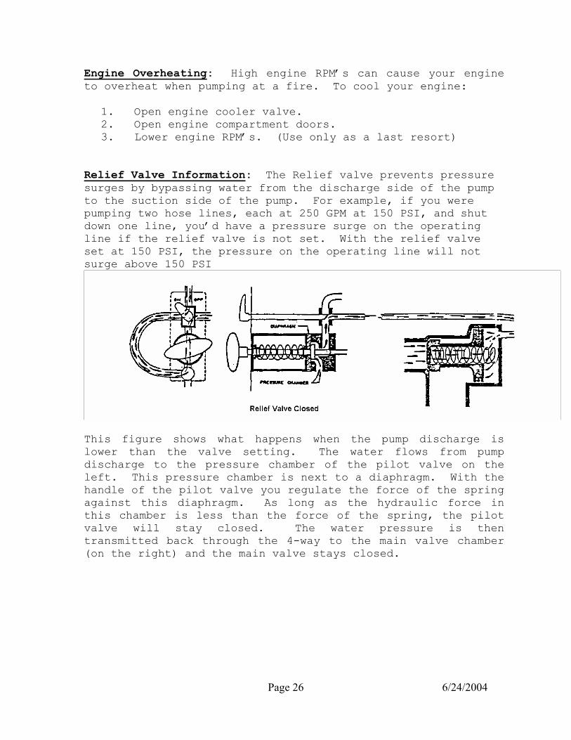
Relief Valve Information: The Relief valve prevents pressure surges by bypassing water from the discharge side of the pump to the suction side of the pump. For example, if you were pumping two hose lines, each at 250 GPM at 150 PSI, and shut down one line, you’d have a pressure surge on the operating line if the relief valve is not set. With the relief valve set at 150 PSI, the pressure on the operating line will not surge above 150 PSI
This figure shows what happens when the pump discharge is lower than the valve setting. The water flows from pump discharge to the pressure chamber of the pilot valve on the left. This pressure chamber is next to a diaphragm. With the handle of the pilot valve you regulate the force of the spring against this diaphragm. As long as the hydraulic force in this chamber is less than the force of the spring, the pilot valve will stay closed. The water pressure is then transmitted back through the 4-way to the main valve chamber (on the right) and the main valve stays closed.

Page 27 6/24/2004
This figure shows you what happens when a pressure rise opens the pilot valve enough to overbalance the main valve. The restricted area around the needle valve in the pilot valve acts as a metering passage to control the flow around it. When discharge pressure gets high enough to compress the diaphragm against the spring in the pilot valve, the needle valve moves to the left. This allows water to “dump” back to pump suction. This, in turn, reduces the pressure in the tube behind the main valve (right). The force on the small end of the main valve (left) is now greater. The valve opens so part of the water being pumped bypasses back to suction, reducing discharge pressure. The main valve opens just enough to reduce discharge pressure to the pilot valve setting. If the discharge pressure drops below the set pressure, the pilot valve reseats, pressure builds up behind the large end of the main valve, and closes it.
Relief Valve Operations Setting the Relief Valve:
1. Turn the Relief Valve ON.
2. Open at least one discharge gate.
3. Raise the RPM’s until you reach the desired pump pressure.

Page 28 6/24/2004
If the YELLOW light turns on before reaching the desired pump pressure, increase the Relief Valve setting to exceed the desired pump pressure by 10 psi. (You now should have a GREEN light). Continue raising the RPM’s until you reach the desired pump pressure.
NOTE: (Each ½ turn clockwise of the Relief Valve increases the Relief Valve setting by approximately 10 psi.) (Each ½ turn counter-clockwise of the Relief Valve decreases the Relief Valve setting by approximately 10 psi.)
4. Turn the Relief Valve counter-clockwise ½ turn at a time
until the pump pressure begins to drop and the YELLOW light turns on.
5. Turn the Relief Valve back (clockwise) ½ turn at a time
until the pressure stabilizes and the GREEN light turns on. THE RELIEF VALVE IS NOW SET and will automatically prevent pressure surges.
Exercising the Relief Valve: Because of the design of the relief valve system, few disorders are apt to occur. If the relief valve operation is sluggish or erratic, the cause can usually be traced to fine sand, grit or other foreign material clogging one of the valves or strainer. Following the instructions listed below will usually restore relief valve operations.
1. With the apparatus engine running, place the truck into pump gear. Turn the relief valve to the OFF position.
2. Remove the strainer rod assembly and clean the strainer
and orifice in the rod end. Stand clear of the relief valve opening and turn the relief valve to the ON position for approximately 5 seconds. A small stream of water will flow from the relief valve flushing the piping.
3. Turn the relief valve OFF. Inspect the condition of the
O-ring and replace if damaged. Hand-tighten the strainer to seat the O-ring, DO NOT use any tools.
Page 29 6/24/2004
4. Open one discharge valve just enough to permit a small
flow of water to keep the pump cool. Raise the pump pressure to 180 psi.
5. Rotate the relief valve handle counter-clockwise all
the way until it bottoms out.
6. Cycle the relief valve lever from ON to OFF holding each position for one second. Do this several times to flush clean water through the relief valve and to exercise the relief valve gate through its full range of travel.
7. Make sure the relief valve is ON and set the relief
valve to the desired pressure.
If this operation does not remedy the situation, contact the FD Shop.
Anytime the pump pressure is changed the relief valve will have to be reset. The relief valve must always be set for the highest pressure being pumped. The relief valve only operates between 75 and 300 PSI, for pressures greater than 300 PSI the relief valve must be shut off. Caution: The Driver Engineer must remain at the pump panel when operating with the relief valve OFF. Extreme caution should be used to prevent pressure surges. This is done by increasing and decreasing RPM with pump panel throttle. Pressure Governor Information: Apparatus equipped with a pressure governor are not equipped with a relief valve; the pressure governor if in the proper mode will provide surge protection for the lines. The pressure governor has two modes: PRESSURE, and THROTTLE. These two modes should not be confused with a two-stage pump which has two stages: PRESSURE, and VOLUME.
Page 30 6/24/2004
When the selector switch is placed in the THROTTLE mode, the toggle switch acts just like the vernier throttle on an apparatus without a pressure governor. As you push the switch up, the throttle is advanced. The pressure governor will maintain that throttle setting regardless of the amount of water being flowed. In the THROTTLE MODE YOU HAVE no surge protection. This mode should only be used in emergency situations when the PRESSURE mode is not operating properly. Most situations require the selection of the PRESSURE mode to safely pump the apparatus. To operate in the PRESSURE mode, perform the normal seat operations and push the selector switch to the PRESSURE mode. As you advance the throttle the pressure will increase. When the desired pressure is reached, release the toggle switch and the apparatus will maintain the pressure you have selected. As the flow increases or decreases the pressure governor will automatically advance or decrease the throttle to maintain the selected pressure. The PRESSURE mode acts just like the cruise control on your car, except that it will maintain a set PSI instead of mph. Each time you pump the apparatus you will have to set the pressure governor, it does not have a memory of the last pressure that was pumped. The pressure governor has other features designed to assist the driver, the automatic shutdown, and the emergency shutdown. The automatic shutdown occurs if you run out of water in the PRESSURE mode and do not take any action to correct it. The pressure governor will automatically go to maximum rpm’s for 5 seconds to build pressure, if it cannot build pressure it will automatically shut down to idle. The emergency shut down is a red button or a on/off switch that will immediately lower the rpm’s to idle when pumping if an emergency occurs. The most important thing to remember about the pressure governor is that you must select the PRESSURE mode if you want to have any surge protection. It is a very bad habit to pump the apparatus in the THROTTLE mode because you will have no surge protection. Use the PRESSURE mode at all pumping incidents to provide surge protection and safety to the firefighters on the line. Time spent drilling with the pressure governor will increase your familiarity and your understanding of how it works, and allow you to feel more comfortable on the scene of an emergency.

Page 31 6/24/2004
APPARATUS INSPECTION
Daily Apparatus Check: The following items shall be checked prior to starting the apparatus:
1. Conference with the “OFF” going driver. 2. Damage Check. Check for any new damage to the
apparatus and verify damage was logged in journal. 3. Check the ground under the apparatus for obvious fluid
leaks 4. Engine oil (generator and other power equipment) 5. Hydraulic oil (hydraulic oil that operates gates or
aerial device). 6. Prime oil and pump oil (if applicable) 7. Power steering fluid 8. Belts and hoses (Check for wear and tightness) ¼” give
when pushed. 9. Batteries (Reading with hydrometer and fluid level) 10. Radiator fluid (Check sight glass and/or remove cap
and visualize) 11. Water in tank (Open hatch and visualize full water
tank) 12. Tires (Visualize pressure, lug nuts, tread depth
(4/32”), and condition) 13. Hose (Load complete and stored properly with crossover
made) 14. Nozzles (Shut-off closed and stored properly) 15. Air bottles and SCBA’s (Proper pressure and operation) 16. Equipment (Visual inventory, secure on apparatus, and
fluid levels) 17. Hydrant and territory notices 18. After a working fire take a full “by the book
inventory” and log it in the Apparatus journal
Page 32 6/24/2004
Start apparatus and check the following:
1. Check under the apparatus for obvious fluid leaks. 2. Engine oil pressure. It must come up within 15
seconds; if not IMMEDIATELY shut the engine down. 3. Air pressure 4. Fuel level 5. Volt meter (12 to 14 volts) 6. Radio (check to see Miami radio is operating). 7. Brakes (Perform “CDL” Brake test). 8. Steering check to see there is less than 2” play on a
20” wheel. 9. Lights (Head, tail, brake, turn, and emergency) 10. Transmission fluid level
Apparatus equipped with a pump check the following: 1. Discharge gates closed and unlocked 2. Caps are secure to intakes and outlets 3. Operate all intake and discharge gates 4. Operate piston intake relief valve 5. Check all discharge bleeders closed, intake bleeders
open 6. Engage pump and operate the following:
a. Open tank to pump valve b. Operate prime device c. Operate relief valve or pressure governor d. Operate transfer valve e. Check for leaking discharge valves f. Operate pump and engine cooling valves
Log all appropriate entries in the Station Journal and report any abnormal items to your Company Officer and/or the Fire Department Shop. NOTE: If the apparatus requires any repairs fill out the “Apparatus Repairs Needed” form.

Page 33 6/24/2004
Weekly Apparatus Check: The following items shall be checked on a weekly basis established by the Station Commander:
1. Tire pressure with gauge 2. Inventory of equipment by book 3. Weight CO2 extinguisher (must be within 10 percent of
total charged weight). 4. Check pressure gauge on dry power 5. Clean the engine 6. Clean the chassis and check the following:
a. Bleed air brakes if not equipped with automatic bleeder
b. Check drive shaft and universal joints c. Check springs and hangers for loose or broken
components, missing bolts and nuts d. Check for any fluid leaks
7. Remove and clean all ladders 8. Operate the piston intake relief valve 9. Check all intakes for screens 10. Check and operate deckgun or aerial nozzle 11. Operate aerial device and check the following if
applicable: a. Check for hydraulic leaks frayed cables or frozen
pulleys b. Check operation of stabilizers (chock front wheels) c. Check aerial operation (elevation, rotation,
extension) d. Lubricate aerial device and water tube
12. Exercise the RELIEF valve
Log all weekly checks in the Apparatus Book and Station Journal. Report any abnormal items to your Company Officer and/or the Fire Department Garage (Shop).
Monthly Apparatus Check: On the first day of each month the Driver-Engineer will make out a monthly apparatus inspection report. This report and the information needed will be derived from close inspection of the apparatus and equipment. Information will be taken from the Apparatus Reference Book, fuel record, etc. Check the O.P.M. for additional information on the monthly apparatus inspection report procedures.
Page 34 6/24/2004
Radiological Check
On the 15th of each month the radiological equipment assigned to each apparatus is to be tested by the on-duty Firefighting and Rescue Companies. If you experience a problem with any component return the entire kit to the Driver Engineer Instructor. Check the O.P.M. for additional information.
ADDITIONAL INFORMATION FOR DRIVER-ENGINEERS
Battery Chargers: The battery charger cord provided in each Fire Station shall be plugged in the charger outlet anytime the apparatus is in quarters. The overhead power drops in the apparatus room are for the battery chargers on apparatus and AC shore power connections ONLY. DO NOT connect any other electrical equipment to these power drops. The battery charger automatically charges both batteries regardless of battery switch position. Remove all items from around battery chargers on apparatus, as they require good ventilation to prevent overheating. Check charger for operation by feeling for vibration or listening for humming sound at location of charger if meter is inaccessible. If the charger does not operate check the following:
a. Battery fully charged 1200 or above b. Blown fuse in charger cord. (Indicator light in
ceiling of most stations will be on.) c. GFI breaker popped. d. Circuit breaker to outlet turned off. e. Charger malfunction.
If battery reading is below 1175, contact the Fire Department Shop at once. The reading of the lowest cell is the recorded reading for that battery.

Page 35 6/24/2004
Underwriters’ Pump Service Test: The Underwriters’ Pump Service Tests play an important part in the rating of our Fire Department. These tests are intended to determine whether the pumps meet specifications while operated by their regular personnel. The test itself consists of:
1. Timing the interval for the pump to prime. 2. Checking the RPM of the engine while performing the
test. The minimum pumping requirements for a Class “A” rating is as follows: Test 1- rated capacity @ 150 net pump pressure for 20 minutes. Test 2- 70% capacity @ 200 net pump pressure for 10 minutes. Test 3- 50% capacity @ 250 net pump pressure for 10 minutes. Test 4- Spurt Test (optional) capacity at 165PSI for 5 min. The Driver-Engineer must pay strict and constant attention to his gauges during the entire test period. He/she is NOT to touch any controls once the test engineer indicates operating test conditions have been reached, other than the following exceptions:
1. Operate the engine cooler. 2. Shut down in an emergency 3. Close gate in case hose bursts.
Additional information will be provided by the person performing the test in regards to hose layout and gating of lines for each apparatus. Pump Operation Procedures for Allison Transmissions: Due to accidents involving pumpers with electric shift, Waterous pumps and Allison automatic transmissions, the following procedures will be followed when shifting from road to pump position to assure that the shift is complete. After positioning apparatus and applying parking brake:
1. With engine at idle speed, put transmission in neutral.
2. Move electric shift switch to pump position. 3. Shift transmission to reverse momentarily IF NEEDED to
release shaft torque, or eliminate butt-tooth condition, then shift to required pumping gear.
4. On apparatus equipped with pump shift indicator lights in the cab and on the pump panel, DO NOT open the throttle unless both green indicator lights are on. When changing the electric shift switch from road to pump position, the red light on the switch panel in

Page 36 6/24/2004
the cab may come on briefly during the shift lever travel. If the pump transmission does not complete the shift from road to pump, the red light on the switch plate will continue to flash until the pump transmission has completed the shift to pump position. When the pump shift has been completed to pump position, the green lights will come on in the cab and also on the pump panel and it is safe to open the throttle.
CAUTION: DO NOT INCREASE ENGINE RPM UNLESS THE GREEN LIGHT LOCATED ON THE PUMP PANEL IS ILLUMINATED. IF THE LIGHT IS NOT ILLUMINATED CKECK THE FRONT DRIVESHAFT TO SEE IF IT ROTATING AT THE CORRESPONDING ENGINE RPM All Driver-Engineers shall know the location and operation of the manual override to engage the pump if the shift motor fails to engage the pump. Operation of L.T.I. Aerial Winches: The front mounted electric Winches installed on the L.T.I. Aerials are designed to operate in a shutdown fail-safe mode if the object being pulled is beyond the winch capacity. The winch cable has a safety factor greater than the winch can pull; therefore, the winch should grind to a halt before the cable will snap, if it cannot pull the load. The winch is to be operated only with the apparatus in a parked or spotted position. The winch operator should wear complete turnout clothing to include gloves and helmet and position himself to the side of the apparatus or within the cab. The cable from the winch should only receive tension from operating the winch itself. Once the cable is attached to the load and tension applied, the apparatus should not be moved either to assist the winch or to gain more tension if the winch won’t pull the load. Caution: If a long stretch of cable is played out between the winch and the object, salvage covers are to be placed over the entire cable length to absorb the shock should the cable snap or break loose from the object under tension.
Page 37 6/24/2004
Foam Operations: There are three parts to a foam system; the foam concentrate, nozzle, and eductor. If any of the three parts are missing or not working properly the foam operation will not be a success. All personnel should be familiar with the parts of a foam system and the proper procedures to implement a foam operation. Foam: The most common type of foam is AFFF. This type of foam is useful on most types of flammable liquid fires and other specific types of fires. The AFFF foam solution is rated for applications of 3% or 6% concentrate. The proper solution is determined by the hazard present. For polar solvents and other alcohol type hazards a solution of 6% foam concentrate is required to control the hazard. If the hazard is a hydrocarbon based product (gasoline, diesel, etc.) a solution of 3% foam concentrate is required. A minimum of 15 gallons of foam concentrate should be carried on each apparatus equipped with a 500 gallon water tank. Nozzle: A Fog nozzle is required to properly apply foam. The nozzle must be fully opened to get the required amount foam to the nozzle. The nozzle and the eductor must also be matched to receive the right concentration of foam. If the nozzle is rated at less GPM’s than the eductor, the eductor may NOT pick up foam, or it may deliver ineffective foam. Eductor: The third part of the foam system is the eductor. The in-line foam eductor is the most common type and the one that is carried on our apparatus. The in-line eductor uses the venturi principle to induce foam concentrate into the water stream. This type of proportioning results in a substantial pressure loss of approximately 70 PSI. For this reason a minimum of 200 PSI is recommended on the input side of the eductor, and a maximum of 200 feet of 1 ¾ inch hose between the nozzle and the eductor, to receive a satisfactory flow of foam. Usually, the eductor will be located on one of the jump lines if the length is to be 200 feet or less. If the length between the apparatus and the nozzle exceeds 200 feet, the eductor should be located in the hose line 200 feet or less from the nozzle using 2 ½ or 3 inch hose to supply the eductor.
Page 38 6/24/2004
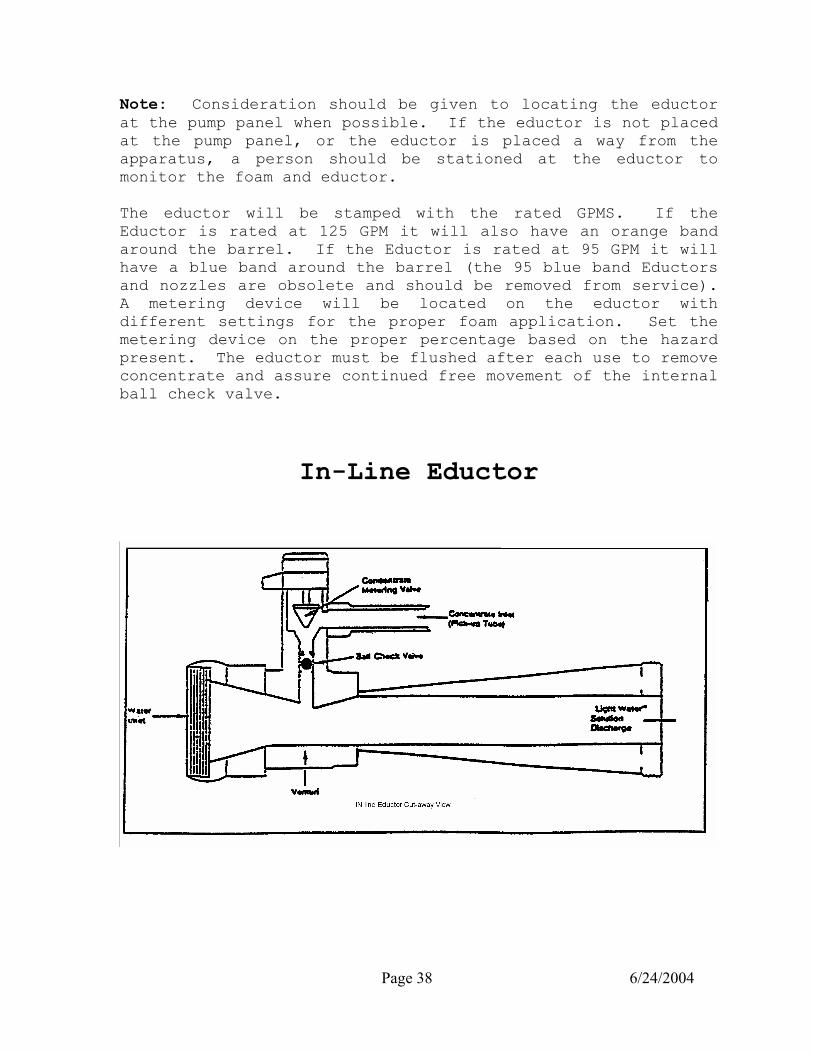
Note: Consideration should be given to locating the eductor at the pump panel when possible. If the eductor is not placed at the pump panel, or the eductor is placed a way from the apparatus, a person should be stationed at the eductor to monitor the foam and eductor. The eductor will be stamped with the rated GPMS. If the Eductor is rated at 125 GPM it will also have an orange band around the barrel. If the Eductor is rated at 95 GPM it will have a blue band around the barrel (the 95 blue band Eductors and nozzles are obsolete and should be removed from service). A metering device will be located on the eductor with different settings for the proper foam application. Set the metering device on the proper percentage based on the hazard present. The eductor must be flushed after each use to remove concentrate and assure continued free movement of the internal ball check valve.
In-Line Eductor
Page 39 6/24/2004
In-line Eductor (cont)
To place the eductor in operation:
1. Locate the eductor 200 feet or less from the nozzle. 2. Verify that the nozzle and the eductor match. 3. Stage all the foam containers (with the caps off) near
the eductor. 4. Set the metering device for the proper hazard. 5. Open the discharge gate to the foam line and pump
standard starting engine pressure. 6. When the foam concentrate reaches the eductor the pump
pressure/engine RPM may need to be adjusted.
Trouble shooting Eductor operations If you do not have foam at the nozzle, check the following:
1. Eductor might be placed more than 200 feet from the nozzle.
2. Mismatched eductor and nozzle. 3. Nozzle not fully opened. 4. Nozzle elevated above pump creating excessive back
pressure. 5. Eductor or nozzle clogged. 6. Ran out of foam in the container. 7. Insufficient pump pressure. 8. Kink in hose line. 9. Some 125 GPM nozzles may be delivering less than 125
GPM while set on straight stream. (Elkhart 125) After completing the foam operation:
1. Flush the nozzle and eductor by educting clean water through the pickup tube.
2. Upon returning to quarters, clean eductor in fresh soapy water.
Page 40 6/24/2004
Drafting Operations: When it is determined that drafting will be required the following must be evaluated: Selecting a draft site: Example: Oceans, lakes, canals, pools, etc. 1. Minimum 3 foot depth (place suction 18” from top 12” from
bottom 2. Keep lift as low as possible (maximum 20’) 3. Water sources other than MFD are only for emergency
operations. 4. Stability of the ground 5. Access to connect hose lines 6. Distance to fire 7. Most important, a location that is safe for the driver Connecting hard suctions: 1. Check for gaskets 2. Look for accumulated dirt or debris inside couplings 3. Attach strainer and tie rope to hard suction. 4. Do not draft without intake screen in place 5. Attach hard suction to intake 6. When lowering hard suction over seawall use chaffing pad. Obtaining a draft: 1. All valves and gates must be closed. (This includes the
Pump Cooler and Engine Cooler valves.) 2. Two stage pumps should be in Volume mode. Currently the Miami Fire Department has two types of pumps, front mounted and midship mounted; each pump requires a slightly different procedure to prime the pump.
Page 41 6/24/2004
To prime a midship mounted pump: 1. Place the apparatus in pump gear. 2. Raise the engine rpm’s to 1,000 to 1,200. 3. Operate the primer. 4. Observe gauges. 5. The priming action should not be stopped until all the
air has been removed and the primer is discharging a steady stream of water.
6. Disengage the primer. 7. Open discharge slowly.
NOTE: (if the pump is a front mounted pump obtain a prime before engaging the pump.) A prime should be obtained within 30 seconds (45 seconds if 1500 gpm’s or larger). If water has not been obtained within the time limit, stop priming and check to find out what the problem is. The most common cause is due to an air leak that prevents the primer from developing enough vacuum. After the pump has been successfully primed, increase the throttle while opening the discharge slowly. A constant movement of water is needed to prevent the pump from overheating, but there is a more important reason to maintain flow at draft. The vacuum to initially prime the pump comes from the primer, but once the pump begins to operate, the primer is no longer used. The vacuum is now maintained by the movement of water through the pump. When no water is being discharged, even the smallest leak may result in a loss of vacuum. Once the desired pressure has been established and hose lines are in service, set the relief valve or pressure governor. The supply of a sprinkler or standpipe system from a draft is prohibited by the Miami Fire Department Standard Operating Procedures. Another source of water will need to be obtained to supply these systems. If a whirlpool develops or drop in pressure is noticed, check the strainer for blockage or sucking air. The suction may be lowered or repositioned to prevent the problem. If movement of the suctions is difficult or impossible, place an object that floats to prevent a whirlpool, or use a pike pole to clear the obstruction. .

Page 42 6/24/2004
After drafting from a water source other than the Fire Department drafting pit, the pump must be flushed with fresh water. To flush the pump, hook up to a hydrant on the opposite side from where the suction was connected for drafting. Open the opposite side large intake first and allow water to flow (this dislodges any debris which the intake screen did not filter out). Cap the large intake and open the spud intakes, allow water to flow, then close. Partially open discharge gates so as to flush all the gates simultaneously. Allow the fresh water to flow out all intakes and discharges for 3 to 5 minutes. If the water tank was filled during the pump operation, the tank will have to be flushed and refilled with fresh water. Remember that any intake on the apparatus must have a screen in place to prevent debris from entering the pump. When flushing the pump DO NOT hook the hydrant to a discharge to “back flush” the pump. NOTE: The entire apparatus and equipment must be hosed down to eliminate any salt spray or contaminated water which adhered to the apparatus.
LIMITS FROM MAINS:
1. With the hydrant open, note the static pressure reading on the intake gauge with all discharges closed.
2. Note the drop in pressure (residual) on intake gauge
when flowing one line. 3. If the drop in residual pressure is 10% or less than
that of static pressure, the main can flow three (3) times more than the GPM already flowing.
Example: Flowing 250 GPM Residual pressure drop of 10% or less is noted. The main can flow three (3) times the amount already flowing
750 GPM’s Total limit from main 1000 GPM’s

Page 43 6/24/2004
4. If the drop in residual pressure is 11% to 15% of static pressure, the main can flow two (2) times more than the GPM’s already flowing.
Example: Flowing: 250 GPM Residual pressure drop if 11% to 15% is noted. The main can flow two (2) times the amount already Flowing 500 GPM Total limit from main 750 GPM
5. If the drop in residual pressure is 16% to 25 % of static pressure, the main can flow one (1) time more than the amount already flowing.
Example: Flowing 250 GPM Residual pressure drop of 16% to 25% is noted. The main can flow one (1) time the amount already Flowing 250 GPM Total limit from main 500 GPM
6. If the difference is over 25%, more water may be available but not as much as is already flowing.
7. It is important that drivers keep a positive reading
on the compound gauge to prevent pump cavitation and fire lines from not having adequate supply. This is extremely important at large fires where multiple apparatus are involved with large GPM flows; apparatus may rob water from each other.
Remember: Main selection is important at large fires.

Page 44 6/24/2004
Five Inch Hose: The hose is three ply construction
1. Outer layer, “Duristaflex”, lightweight, highly
flexible and ribbed for added resistance to wear abrasion.
2. Polyester reinforcement, high-tensile, polyester
fiber for added strength, minimal expansion and non-absorbency.
3. Inner layer, polyurethane, for high tensile strength
with minimum weight and bulk and far greater resistance to aging.
Five inch hose uses sexless couplings. If the coupling is not completely locked (lugs lined up), and it not equipped with a locking mechanism, the coupling can back off or separate when the line is charged. Any time when making a connection with 5 inch hose, make sure the hose is not twisted and place a counter-clockwise twist in the hose prior to connecting. When loading the hose make sure that the couplings pull straight out and do not flip over when laying out the hose (make a Dutchman). To make the connections faster and easier, lubricate the seal and the areas of metal-to-metal contact with silicon spray. Each 100 foot section weighs approximately 104 pounds empty. When charged; figure one gallon per foot or approximately 800 pounds. While it is common practice to move hose by grabbing both ends, this is not recommended with large-diameter hose. If you must drag hose, drag it flat not on its edge. When loading hose from a roll, do not lay hose on side and unroll, roll it out.
The Humat Valve should be used when laying a forward supply line and the distance from the hydrant to the fire is greater than 300 feet. The use of the Humat Valve on forward evolutions of less than 300 feet is not necessary unless specified by the officer. When using a Humat Valve at high flows a pressure and GPM loss may be experienced until a second pumper boosts the pressure.

Page 45 6/24/2004
The low friction loss in 5 inch hose allows for longer lays and more gpm’s without placing a pumper at the hydrant to boost pressure in the supply line. The use of Humat Valve should be limited to long lays that require a large flow of water and require additional pressure to move the water to the fire. When laying 5” hose, a speed of approximately 10-15 mph is required to prevent the hose form striking the tailboard or paying out of the hose bed too fast. Even though it is not recommended to drive over charged hose, one may proceed at a 45 degree angle with sufficient momentum in an emergency, but in no case ever drive over couplings. Do not allow non-emergency vehicles to drive over the hose in any case, cars can get hung up on the hose and tear it or the catalytic converter can burn through it. Keep the hose away from apparatus exhausts to prevent burning the hose. When charging the hose make sure the hose has a place to go when pressurized, allow room for the hose to make a smooth bend radius to prevent kinking. Anytime 5 inch hose is supplying a pump, there must be a Pressure Relief Valve in the system. This is accomplished by using the Piston-Intake-Relief-Valve, on non-Young pumpers or quints (Young apparatus have a pressure relief valve built into the intake manifold piping). Prior to opening any intake with 5 inch hose supplying it, the air must be bleed off to prevent cavitating the pump. The following pressures have been established for 5 inch hose: Service Test Pressure is 200 psi for 5 minutes. Working Pressure is 150 psi. Maximum Operating Pressure is 185 psi. Five inch hose is superior to other smaller sizes of hose in supplying a large amount of water with very little friction loss. The hose should be used as a supply hose and not as a high pressure fire line. Pressures above 150 psi are not recommended and are approaching the test pressure of the hose. The intake pressure relief valves on the apparatus are set at 150 psi; pressures above 150 psi will activate the pressure relief valve and prevent additional pressure from damaging the intake plumbing on
Page 46 6/24/2004
the apparatus. Remember to think of the 5 inch hose as an above ground water main, that moves the water to the fire with very little friction loss, and you will use the hose to its best capability. To calculate friction loss in the 5 inch hose, refer to the hydraulics section of this packet for more information.
AERIAL OPERATIONS
Types of Aerials: there are four types of aerial devices; aerial ladders, aerial ladder platforms, telescoping aerial platforms, and articulating platforms. Each type of aerial has specific advantages and disadvantages for each application. Specific information on the operation and capacities of each type of device is found in the apparatus manuals for that particular apparatus. While each aerial may require a different manual for the proper operation of that device, several general concepts of aerial operations will be covered in this section. Remember, the aerial operation manual for your apparatus will take priority over any general concepts covered in this section. Positioning of Aerial Apparatus: The positioning of aerial apparatus is one of the most critical aspects of operating an aerial device. If the ladder is 10 feet too short or cannot reach the target, the aerial device might as well have been left at the station. The aerial must be positioned to reach the most targets possible with one spot. Once the aerial has been positioned, the chances to move it are greatly reduced and very time consuming. When positioning the aerial device take into consideration the following conditions: 1. Power lines or overhead obstructions. 2. Collapse zones of the building. 3. Able to reach the most victims. Fire floor first,
floor above the fire second, top floor third, then all the floors in-between.
4. Access to the roof. 5. Stability of the ground. 6. Clearance for outriggers.(you may have to short
jack) 7. Safest use of the device.

Page 47 6/24/2004
Aerial Setup: Once the proper position has been established, the aerial must be setup to reach the targets or perform its task. Apply the parking brake and perform the proper seat operations for the particular aerial device. On most aerial devices the front wheels should be chocked to prevent the aerial from moving. The next step is to stabilize the apparatus. The outriggers must be fully extended to meet the manufactures capacities for that device. Plates must be used to increase the area of contact for the outriggers. The plates should be placed after the outriggers have been extended out from the apparatus. This is for safety and to accurately determine where the plates should go. If the plates are not placed directly on pavement be suspicious of wash out (a condition where the ground may be washed away from under the plates). The apparatus should then be leveled using the levelers starting with the low side then moving to the high side. Follow the manufactures recommendation on determining proper stabilization of the aerial device. Once the device has been leveled, place the pins (leave ¼” clearance) in the outriggers (if the device uses pins). CAUTION: When the apparatus rear wheels are off the ground you do not have rear wheel parking brakes. NOTE: All MFD aerial type apparatus are to be used in the unsupported position. Sequence of Operations: The proper sequence of aerial operations is as follows: Elevate, Rotate, Extend, and Lower. The last movement of the aerial device should be down to the target to prevent a victim from jumping and placing a shock load on the aerial device. When possible, the victim that is located at the top of the building should be rescued first to prevent them from being tempted to jump to the aerial device. The apparatus manual shall be consulted to determine if the aerial device should be placed on a building to increase the capacity, or if the device should not contact the building. All controls should be operated in a smooth manner and the controls should never be allowed to spring back to a neutral position. When the aerial device is approaching a target that the operator has trouble judging the distance to, a guide should be used. Standard hand signals should be used to advise the operator of the proper movement that is required. (See OPM 4-21)
Page 48 6/24/2004
When moving away from a target, reverse the sequence of operations. Use caution when performing more than one movement at a time. Make sure that the device is lined up to the cradle prior to bedding the aerial device. Once the device is stowed, remove the pins in the outriggers, and retract the outriggers. When the outriggers are retracted, pickup the plates and stow them in the brackets. Remove the wheel chocks and disengage the PTO. Aerial Safety: The most important factor when operating an aerial device is the safety of the firefighters and the citizens. Safety precautions are as follows: 1. Over the rear operation (45 degrees to each side of the
center line) is the safest and most stable position with the greatest reach.
2. Keep all aerial devices at least 10 feet away from power lines.
3. Personnel should be on the apparatus or off the apparatus, do not stand on the ground and operate the Aerial device.
4. NEVER extend or retract the ladder while personnel are on the ladder
5. Notify on board personnel before rotating, elevating or lowering the ladder.
6. The spacing and number of personnel on the aerial device is controlled by the driver. Never Overload the Aerial Device.
7. Low angles and full extension should be avoided. 8. When shutting off the water to a ladder pipe, close all
gates very slowly. 9. When working on ladder wear a ladder belt. 10. Keep SAFETY in mind at all times.

Page 49 6/24/2004
SAFE EMERGENCY VEHICLY OPERATION POLICY OPM 4-21 01.01 PURPOSE:
To provide the City of Miami Fire Department employees with general driving and safety regulations for operating emergency vehicles. To reduce injuries and property damage by establishing standard procedures to avoid vehicular accidents To incorporate the general driving rules and regulations of the State of Florida and the Miami Fire Department, into a single policy.
01.02 POLICY:
It is the policy of the City of Miami, Fire-Rescue Department to provide standardized rules and regulations to increase safety and reduce injuries and property damage while operating emergency vehicles.
01.03 PROCEDURE:
A. All members of the City of Miami Fire-Rescue
Department shall have a valid State of Florida driver’s license.
1. Drivers of all fire and rescue apparatus must
possess, as a minimum, a Class “D” license with an “E” endorsement.
2. Drivers within the past 3 years, shall not have
been convicted of reckless driving or driving under the influence of alcohol or controlled substance and has not had a drivers license suspended under the point system.
3. Drivers of ALS and BLS vehicles must
satisfactorily complete an Emergency Vehicle Operator’s Course (EVOC) to operate EMS vehicles.

Page 50 6/24/2004
B. Any member whose license has been suspended or revoked shall immediately notify the Fire Chief by memo and shall be prohibited from driving any city vehicle. This notification does not affect the members pay status as a driver except as outlined in the OPM 4-5
C. Any member who has satisfactorily completed the
prescribed probationary period for a Firefighter will be eligible to drive, operate and care for Fire Department emergency apparatus, after satisfactorily completing the Reserve Driver-Engineer Course.
1. Drivers of fire apparatus must be approved by the Driver-Engineer instructor in the proper care, operation and handling of the unit to which the driver is assigned.
2. In the event there is no assigned Driver-
Engineer present to drive the apparatus, the Company Officer will assign a Firefighter that he/she feels is competent to perform the required duties.
3. In an emergency, any Fire Department personnel
may be assigned by a Company Officer to drive an emergency vehicle.
D. Drivers of fire department vehicles shall be
directly responsible for the safe and prudent operation of the vehicle. When the driver is under the direct supervision of an officer, that officer shall also assume responsibility for the safe and prudent operation of the vehicle.
E. Drivers shall inspect their apparatus on a daily
basis. Items to be inspected shall include, but are not limited to: all fluid levels, brakes, steering, tires, lights, pump operation, equipment, and overall apparatus condition. Questions on items that may prove to be unsafe shall immediately be directed to the Company Officer. The Company Officer shall insure that the On-call Mechanic or Fire Department shop is notified immediately.
Page 51 6/24/2004
F. All personnel shall be seated in a vehicle seat
and wearing the seat belt provided at all times the vehicle is in motion whether on an emergency or routine movement. No vehicle is to be operated with more personnel than there are seat belts. It shall be prohibited for any personnel to stand or kneel on the jump seat or ride on the exposed positions (tailboard, back step, running board, bumpers, etc.) of any Fire-Rescue vehicle when it is in motion other than the following exceptions: 1. Members actively performing necessary emergency
medical care during patient transport where adherence to the policy would compromise patient care.
2. Participation in parades where vehicle movement
is under controlled conditions.
3. During hose loading operations members shall be allowed to stand on the tailboard or occupy the hose bed only when the following conditions are complied with:
a. There shall be at least one member who
has an unobstructed view of the hose loading operation and be in visual and voice contact with the apparatus driver. If visual or voice contract is lost the driver shall stop immediately.
b. Non-fire department vehicular traffic shall be excluded from the area or shall be under the control of authorized traffic control persons.
c. Apparatus should be driven in a forward direction at a speed of 5mph or less. If backing is required, extreme caution shall be used.
d. Prior to the beginning of each hose loading operation, the situation shall be evaluated to ensure compliance with all of the above provisions. If any provision is not met, hose loading shall not take place.
Page 52 6/24/2004
4. During backing operations a member may guide the driver from the rear of the apparatus on the tailboard using the standard Miami Fire Department horn signals.
G. Drivers shall be responsible for seeing that
equipment is in its proper (safe) position, hose stowed properly, and compartment doors are closed before moving the apparatus.
H. Where tools, equipment, or SCBA are carried
within enclosed seating areas, such items shall be secured by a positive mechanical means of holding the item in its stowed position or placed in a compartment with a positive latching door.
I. To avoid contact with overhead doors, drivers
should not:
1. move the vehicle into an overhead door opening when the door is still moving up or down:
2. stop or park a vehicle in an overhead door opening when possible;
3. activate an overhead door when a vehicle is in the door opening;
4. activate an overhead door from any position which precludes full view of the vehicle and the door either by the activating party or an observer;
J. During non-emergency travel, drivers shall obey
all traffic control signals and signs, and all laws and rules of the road of the State of Florida.
K. When an apparatus is on a routine movement or
responding to an alarm, the donning of a helmet is optional.
L. When an apparatus is on a routine movement and
other than an EMS alarm is received, the apparatus will be stopped in a safe area, prior to response, for donning of protective clothing.

Page 53 6/24/2004
M. During emergency and routine movements, vehicles must come to a complete stop at all unguarded railroad crossings. Drivers must assure that it is safe to proceed before crossing tracks. Caution must also be exercised when approaching and crossing guarded railroad crossings. Drivers must assure that it is safe to proceed in both directions before crossing tracks.
N. Drivers must back their vehicles safely.
1. Fire Apparatus: Two crew members shall be
assigned to assist the driver when backing to prevent accidents. One member will observe from a position at the rear of the apparatus and must have visual contact with the driver at all times. If at any time visual contact is lost with the member at the rear, the driver shall stop the apparatus. Standard hand signals, as defined in this policy, shall be used to guide the driver. If the apparatus is equipped with a tailboard, the member may observe and guide the driver from the tailboard after signaling the driver with the standard Miami Fire Department horn signals as defined in this policy. Additional personnel may used to control traffic or observe the front side opposite the driver when necessary.
2. Rescue Apparatus: Personnel assigned to EMS
vehicles may guide the driver from the rear of the patient compartment after assuring the area is clear. The driver shall establish voice contact with the member at the rear of the patient compartment prior to backing the vehicle. If voice contact is lost the driver will stop immediately.
O. Emergency responses to incidents shall be
governed by the following Florida State Uniform Traffic Control Laws:
Page 54 6/24/2004
State Statute 316.072: Authorized Emergency Vehicles
1. The driver of an authorized emergency
vehicle, when responding to an emergency call, or when responding to a fire alarm, but not upon returning from a fire; may exercise the privileges set forth in this section, but subject to the conditions herein stated, except when otherwise directed by a police officer, may:
a. Park or stand, irrespective of the
provision of this chapter; b. Proceed past a red or stop signal or
stop sign, but only after slowing down as may be necessary for safe operation;
c. Exceed the maximum speed limits so long as he/she does not endanger life or property;
d. Disregard regulations governing direction or movement or turning in specified directions, so long as he does not endanger life or property;
2. The foregoing provisions shall to relieve
the driver of a vehicle specified in paragraph (1) from the duty to drive with due regard for the safety of all persons, nor shall such provisions protect the driver from the consequences of his reckless disregard for the safety of others.
State Statute 316.271: Horns and Warning Devices:
Every authorized emergency vehicle shall be equipped with a siren, whistle, or bell, capable of emitting sound audible under normal conditions from a distance of not less than five hundred feet and of a type approved by the department, but such siren, whistle, or bell shall not be used except when the vehicle is operated in response to an emergency call or in the immediate pursuit of an actual or suspected violator of the law, in which event the driver of the vehicle shall sound the siren, whistle, or bell when reasonably necessary to warn pedestrians and other drivers of the approach thereof.

Page 55 6/24/2004
State Statute 316.126: Operation of Vehicles and Actions of Pedestrians on Approach of Authorized Emergency Vehicle.
(1) Upon the immediate approach of an authorized emergency vehicle, while en route to meet an existing emergency, the driver of every other vehicle shall, when such emergency vehicle is giving audible signals by siren, exhaust whistle, or other adequate device, or visible signals by the use of displayed blue or red lights, yield the right-of-way to the emergency vehicle and shall immediately proceed to a position parallel to, and as close as reasonable to the closest edge of the curb of the roadway, clear of any intersection and shall stop and remain in position until the authorized emergency vehicle has passed, unless otherwise directed by any law enforcement officer.
(2) Every pedestrian using the road right-of-way shall
yield the right-of-way until the authorized emergency vehicle has passed, unless otherwise directed by any police officer.
(3) Any authorized emergency vehicle, when en route to meet an existing emergency, shall warn all other vehicular traffic along the emergency route by an audible signal, siren, exhaust whistle, or other adequate device or by visible signal by use of displayed blue or red lights. While en route to such emergency, the emergency vehicle shall otherwise proceed in a manner consistent with the laws regulating vehicular traffic upon the highways of this state.
(4) Nothing herein contained shall diminish or enlarge any rules of evidence or liability in any case involving the operation of an emergency vehicle.
(5) This section shall not operate to relieve the driver of an authorized emergency vehicle from duty to drive with due regard for the safety of all persons using the highway.

Page 56 6/24/2004
P. Apparatus responding on an expressway shall use their lights and siren when reasonable necessary to warn other drivers. Siren and air horn shall be used at the discretion of company officer to reasonably warn others.
Q. All fire department vehicles that are responding to an
emergency shall come to a complete stop prior to passing a school bus that is loading or unloading children. After a complete stop is made and at such time that it is determined that no children would be endangered, the vehicle may be moved to proceed to the emergency. 1. This rule applies to both public and privately owned
school buses, regardless of whether or not the bus is properly fitted with stop lights and stop signs. If it is obvious that the bus is transporting children and is stopped and is in the process of loading or unloading children the fire department vehicle shall abide by the intent of the requirement.
2. Fire department vehicles are exempt from this requirement when Metro or City buses are transporting their regular passengers; however exercise extreme caution when passing these buses when loading or unloading passengers.
R. When following another apparatus on an emergency
response, the following guidelines shall apply:
1. Maintain a four (4) second interval between apparatus traveling under 40 mph. A five (5) second interval shall be maintained for speeds over 40 mph. The following distance also applies on routine movements.
2. Drivers should maintain a greater interval
between apparatus when adverse weather conditions are encountered.
3. No emergency vehicle shall pass another
emergency vehicle responding to an incident, unless advised to do so by the lead vehicle.
4. Drivers should be aware of motorists that
may pull into their paths after yielding the right-of-way to leading emergency vehicle.
Page 57 6/24/2004
S. Drivers must be aware of the height,
weight, and ground clearance limitations of their vehicles. When tight clearance situations are encountered, a member must dismount and guide the driver.
T. Apparatus equipped with a Telma brake
retarder or other auxiliary braking system shall have the switch in the off position in wet or slippery conditions. The brake retarder should be in the on position at all other times.
U. When members are operating on or in
aerial devices, they shall be secured to the aerial device by a safety belt. Aerial ladders shall never be extended or retracted with personnel on the ladder except in life threatening situations. An aerial operator must be at the ground control console at all times when personnel are in or on an aerial device.
V. Apparatus shall be positioned away from
overhead power lines when possible. All aerial devices shall maintain a minimum ten (10) foot clearance between the aerial device and any overhead power line.
W. Standard hand signals, as defined in
this policy, shall be used to assist the aerial operator in positioning the aerial device.
X. Apparatus shall be utilized as a shield
from oncoming traffic wherever possible. The apparatus shall have visual warning devices on, traffic cones, warning flares, or other appropriate devices shall be used to warn oncoming traffic.

Page 58 6/24/2004
STANDARDIZED MIAMI FIRE DEPARTMENT HORN SIGNALS A. One short blast- “STOP”
B. One continuous blast “EMERGENCY STOP”
C. Two short blasts- “GO AHEAD”
D. Three short blasts- “BACK UP”
STANDARDIZED HAND SIGNALS
RIGHT or LEFT
Point in the desired direction with one hand and with the other hand motion in a back and forth direction
BACK UP
Hands up at shoulder height and motion in a back and forth direction.
STOP
SWING
Cross arms in front of chest or above head to indicate stop. Point in the direction of the desired rotation.
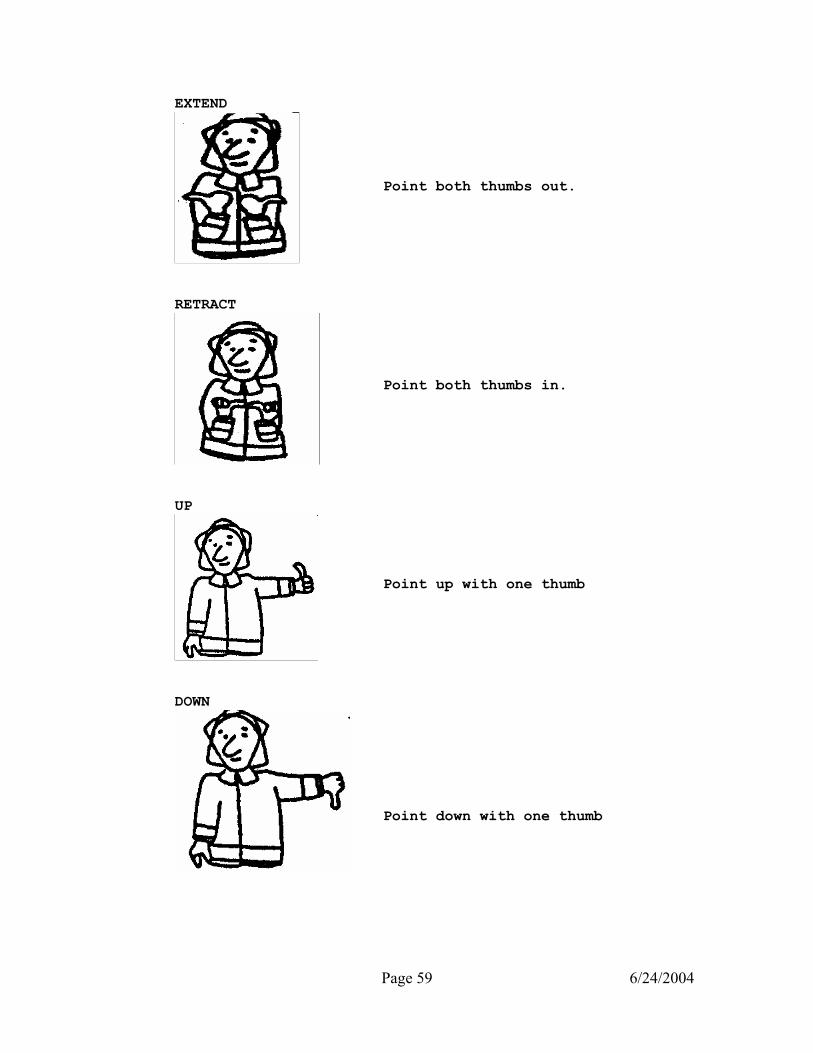
Page 59 6/24/2004
EXTEND
RETRACT
UP
DOWN
Point both thumbs out. Point both thumbs in. Point up with one thumb Point down with one thumb

Page 60 6/24/2004
OFFICIAL NOTICE: ____________________ DATE: JULY 21, 1998 SUBJECT: REVISED VEHICLE SHUT DOWN PROCEDURES THE FOLLOWING GUIDELINES HAVE BEEN PROPOSED TO ASSIST DRIVERS IN DETERMINING WHEN AN APPARATUS NEEDS TO BE SHUT DOWN: WHEN PARKED ON THE SCENE OF AN EMERGENCY INSIDE POLICE LINES, AND THE VEHICLE IS NOT BEING USED TO BLOCK TRAFFIC, PROVIDE EMS CARE, OR IS LEFT UNATTENDED THE APPARATUS SHALL HAVE ALL ELECTRICAL EQUIMENT TURNED OFF AND THE VEHICLE SHUT DOWN. THE FOUR WAY FLASHERS MAY BE LEFT ON IF NECESSARY. ON ROUTINE MOVEMENTS WHEN THE APPARATUS IS LEFT UNATTENDED FOR A PERIOD OF 5 MINUTES OR MORE THE APPARATUS SHOULD BE SHUT DOWN. ALL ELECTRICAL EQUIPMENT SHALL BE TURNED OFF, EXCEPT THE FOUR WAY FLASHERS MAY BE USED IF PARKED ON THE SIDE OF A ROAD. ON THE SCENE OF AN EMERGENCY, THE APPARATUS SHALL BE USED TO BLOCK TRAFFIC IF NECESSARY AND PROTECT THE CREWMEMBERS WORKING AT THE SCENE. THE APPARATUS SHALL BE IN A HIGH IDLE MODE TO PREVENT DRAINING THE BATTERIES. THE USE OF WHITE LIGHTS (STROBES, HEAD LIGHT FLASHERS) SHALL BE LIMITED TO PREVENT BLINDING ONCOMING DRIVERS. THE USE OF FOUR WAY FLASHERS AND TRAFFIC CONES IS ENCOURAGED ON ALL EMERGENCY SCENES TO INCREASE SAFETY. EMS ALARMS REQUIRE THE APPARATUS ENGINE BE KEPT RUNNING TO COOL THE PATIENT COMPARTMENT. THE APPARATUS SHALL HAVE THE HIGH IDLE ACTIVATED AND THE NON-ESSENTIAL EMERGENCY LIGHTS (WHITE STROBES AND HEADLIGHT FLASHERS) SHALL BE SHUT OFF IF THE APPARATUS IS PARKED IN A SAFE LOCATION OR TO PREVENT BLINDING DRIVERS. TURBO CHARGED ENGINES REQUIRE A 5 MINUTE COOL DOWN PERIOD TO PREVENT DAMAGING THE ENGINE. DRIVERS SHALL INSURE A 5 MINUTE COOL DOWN PERIOD OCCURES AFTER A HEAVY LOAD (PUMP OPERATIONS, AERIAL OPERATIONS) HAS BEEN PLACED ON THE ENGINE. THE ITMES NOTED ABOVE ARE GUIDELINES THAT CAN BE MODIFIED FOR A SPECIFIC SITUATION. EACH SITUATION SHOULD BE EVALUATED TO DETERMINE THE SAFEST ACTION. DRIVERS AND COMPANY OFFICERS SHALL STRIVE TO ACHIEVE THE DESIRED RESULT OF REDUCING WEAR AND PROLONGING THE LIFE OF THE ENGINE WHILE PROVIDING PROTECTION AND SAFETY FOR THE FIREFIGHTERS. INITIATOR: THOMAS KLIMOSKI, CAPT. DRIVER-ENGINEER INSTRUCTOR

Page 61 6/24/2004
OFFICIAL NOTICE: 98033 SUBJECT: ALPHA RESPONSES THE MEDICAL PRIORITY DISPATCH SYSTEM ALLOWS A 12-MINUTE RESPONSE TIME FOR LOW PRIORITY ALPHA RESPONSES. THESE REQUESTS FOR SERVICE ARE CONSIDERED NON-EMERGENCY AND THEREFORE HOT RESPONSE IS UNNECESSARY. LAST YEAR THE SERVICE EVALUATION COMMITTEE DETERMINED THAT COLD RESPONSE ON ALPHA CODED ALARMS WOULD BE LEFT TO THE OFFICERS DISCRETION. AFTER CAREFULLY CONSIDERING THIS POLICY, WE HAVE DETERMINED THAT EFFECTIVE IMMEDIATELY, ALL UNITS DISPATCHED ON ALPHA ALARMS WILL RESPOND COLD, THIS MEANS ROUTINE RESPONSE WITH NO LIGHTS OR SIREN. THE OFFICER HAS THE DISCRETION TO RESPOND HOT IF NECESSARY DUE TO TRAFFIC CONDITIONS OR OTHER FACTORS THAT MIGHT UNDULY DELAY THE RESPONSE. IF IT IS DETERMINED AFTER ARRIVAL AND EVALUATION, REGARDLESS OF THE INITIAL DISPATCH RESPONSE MODE (BRAVO, CHARLIE OR DELTA), THAT THE PATIENTS CONDITION IS NON-LIFE THREATENING, A COLD TRANSPORTAION TO A MEDICAL FACILITY WILL BE USED. INITIATOR: CHIEF C.A. GIMENEZ, DIRECTOR DEPARTMENT OF FIRE-RESCUE END OF NOTICE
FIRE SERVICE HYDRAULICS
Hydraulics is that branch of applied mechanics that deals with the physical characteristics exhibited by fluids at rest and in motion. The branch of hydraulics concerned with the study of fluids at rest is called hydrostatics, while the study of fluids in motion is called hydrokinetics. The fire service is concerned with how to deliver water efficiently to the seat of the fire to accomplish its goals. The study of hydraulics has confused many firefighters, but by following a few simple rules the mystery of hydraulics can be easily understood. Six Principles of Fluid Pressure: There are six basic principles that apply to fluid pressure. They are: 1.
Liquid pressure is exerted in a perpendicular direction to any surface on which it acts.

Page 62 6/24/2004
2. 3. 4. 5. 6.
At any given point beneath the surface of a liquid, the pressure is the same in all directions. Pressure applied to a confined liquid from without is transmitted in all directions without a reduction in intensity. The pressure of a liquid in an open vessel is proportional to the depth of the liquid. The pressure of a liquid in an open vessel is proportional to the density of the liquid. Liquid pressure on the bottom of a vessel is unaffected by the size and shape of the vessel.
These six principles determine the action of pressure upon fluids. It is important that the firefighter understand these principles before attempting to understand the type of pressures. Five Types of Pressure: Pressure may be expressed as a force of energy. Compound gauges read pressure in PSI (Pounds per Square Inch) and vacuum in inches of mercury. The five types of pressure are: 1. Static Pressure- is the pressure of water when it is
not moving.
2. 3. 4. 5.
Flow Pressure- is the pressure at a discharge opening while water is flowing. Residual Pressure- is the pressure remaining at the source while water is flowing. Atmospheric Pressure-is the weight of air surrounding us. At sea level it is 14.7 PSI. Back Pressure- is the pressure loss or gain due to elevation.
The fire service uses pressure to move water through hose lines and deliver the required GPM’s to the nozzle. Gauges on the apparatus indicate the pressure in the lines and water available in the hydrant.
Page 63 6/24/2004
Friction Loss: As water is moving through hose it can flow in one of two ways. The two types of water flow are: 1. Laminar Flow- the water flows in even parallel layers,
this occurs at low velocities. In 2 ½” hose it is less than 100 GPM.
2. Turbulent Flow- the water flows in irregular patterns. The turbulent flow is the result of outer layer of water rubbing with the hose to the extent that there is no longer a layering of the water. The flow in fire hose is usually turbulent.
During turbulent flow, friction loss is a function of the relative roughness of the hose lining, the liquid viscosity and the velocity of the water (GPM). Viscosity is the tendency of a liquid to possess internal resistance to flow. The FRICTION LOSS in hose is governed by five fundamental rules: 1. Friction loss varies with the relative quality of the
hose.
2. Friction loss varies directly with length.
3. Friction loss varies approximately with the square of the velocity. For 100 GPM and above2Q2 +Q = FL per 100’ of 2 ½” hose. For less than 100 GPM 2Q2 + 1/2Q Q = GPM 100
4. 5.
For a given velocity, friction loss varies inversely as the fifth power of the hose diameter. D5 D5 For a given velocity, friction loss is nearly independent of pressure. Example 100 GPM at 100 PSI has nearly the same friction loss as 100 GPM at 200 PSI.
Page 64 6/24/2004
What does all this mean to the average firefighter? It means that the best way to reduce friction loss is to increase the size of the hose. Also, to reduce friction loss you can reduce the length, reduce the gallons flowing, buy new hose, or add another line. As you can see some of the options are better than others. Maximum Efficient Flow: The size of the hose limits the amount of water that can be forced through the hose. These limits are known as the maximum efficient flow. The limits are as follows:
1 ½ inch hose 100 GPM 1 ¾ inch hose 200 GPM 2 ½ inch hose 300 GPM 3 inch hose 500 GPM 5 inch hose 1200 GPM
These limits are for water flowing through a length of hose. These limits should serve as a guideline to determine how many lines are needed to supply a given amount of water. Trying to force more water than the maximum efficient flow will result in an increase in friction loss and increased turbulence in the hose line. To flow a total amount of water greater than the maximum efficient flow of that line, another line should be added. Standard Starting Engine Pressure: The calculation of friction loss can be a time consuming one on the scene of a fire. The fire service many times can not wait for the driver to calculate friction loss for the evolution. For these particular cases the Miami Fire Department has determined a standard starting engine pressure for most evolutions. These pressures are used only to “get water flowing” while the driver calculates the proper friction loss for the evolution.

Page 65 6/24/2004
STANDARD STARTING ENGINE PRESSURE
Multiversals 100 PSI Supply Lines 100 PSI Sprinkler Systems 100 PSI Handlines 125 PSI Standpipe Systems 150 PSI Ladder Pipes 150 PSI L.T.I. Aerials 170 PSI AFFF Foam Lines 200 PSI Driver-Engineers shall be familiar with these Standard Starting engine Pressures and use these pressures as a guideline to establishing a safe flow of water until a more accurate pressure is determined. Driver-Engineer Rule of Thumb Supplement: The Driver-Engineer must know and be familiar with all of the nozzles carried on his/her apparatus and on other apparatus in the City of Miami. The GPM’s of a given nozzle must be known to accurately calculate the friction loss for a given layout. This supplement lists all nozzles currently carried on apparatus in the City of Miami. Complex calculations can be done to determine the exact GPM’s for a given pressure and nozzle opening, but by knowing the standard nozzle pressure and the GPM’S at that pressure, those calculations are not needed. Nozzles are grouped according to the type of stream they produce and if they are a handline or a master stream.

Page 66 6/24/2004
Familiarize yourself with the nozzles and GPM’S each will deliver at the standard nozzle pressure on the following page. Time spent reviewing this information will payoff as you begin to calculate friction loss and must know the GPM’S for each nozzle.
The FIRST step in learning hydraulics is memorizing the various Nozzles. YOU must memorize the flow capabilities for each, as well as the nozzle pressure required for an effective hose stream.

Page 67 6/24/2004
TIP SIZE GPM @ SNP TYPE OF LINE STREAM & S.N.P. (PSI)
Akron SM-3F Akron 4517 Marauder 4315 Elkhart 125 Elkhart 250 Elkhart 125/75
10-75
125 95
125
250
125
HAND LINE FOG @ 100 PSI
“ “ “ “
75 PSI
Elkhart SM 100 E LTI Task Force Akron Turbomaster 1755 Akromatic 2000
300-1000
500-1000
500-1250
(Fixed Gallonage)
500-1500
MASTER STREAM FOG @ 100 PSI
“ “
*FOG @ 80 PSI *
7/8” 1” 1-1/8” 1-1/4” Piercing Nozzle Bresnan Distributor
150
200
250
300
150
300
HAND LINE SOLID STREAM @ 50 PSI
“ “ “ “ “ “
1-1/4” 1-3/8” 1-1/2”
1-3/4” 2”
400
500
600
800
1050
MASTER STREAM SOLID STREAM
@ 80 PSI “ “ “ “
Page 68 6/24/2004
Engine Pressure CALCULATIONS How to Figure Engine Pressure: To figure engine pressure use the following formula: FL Friction Loss X HU Hose Units TFL Total Friction Loss NP Nozzle Pressure AP Appliance Pressure BP Back Pressure SP Standpipe or Sprinkler EP Engine Pressure When calculating engine pressures always write down the complete formula to prevent overlooking any of the factors. Each of these factors will be taken one at a time working our way down the formula. Calculating Friction Loss: To figure friction loss for the formula you must know the amount of water flowing through the hose. The first question you should ask yourself is how much water is flowing through the hose? You must know what nozzle you are using and the GPM’s that it flows at it’s proper nozzle pressure. Once you determine the amount of water flowing through the hose you can calculate friction loss. To find friction loss the “Q” formula or the rule of hand may be used. The “Q” Formula: This formula is used for flows of 100 GPM or more through 2 ½” hose. For flows of less than 100 GPM, use a factor of 2 for the friction loss. The “Q” formula is as follows: Q = GPM 2(Q2) + Q = FL (per 100 feet of 2 ½” hose) 100 Example: To calculate the friction loss for 200 GPM the formula works as follows: Q = 200 2 x ( 2 squared ) + 2 = FL 100 2 X ( 4 ) + 2 = FL 8 + 2 = FL Q = 2 10 = FL in 100’ of 2 ½” hose

Page 69 6/24/2004
As you can see the formula requires some complex calculations that are difficult on the fire ground. If the flow is not an even number the calculations are even more difficult. To calculate for 250 GPM: Q = 250 2 x (2.5 squared) + 2.5 = FL 100 2 x (6.25) + 2.5 = FL 12.5 + 2.5 = FL Q = 2.5 15 = FL in 100’ of 2 ½” hose Most drivers do not carry a calculator with them on the fire ground to figure friction loss. A simpler way was devised to calculate friction loss on the fire ground, the rule of hand. 2½” Hose Rule of Hand: Utilize the following chart to determine friction loss with the rule of hand:
The numbers at the top of each finger represent GPM’s in hundreds. The numbers at the base of each finger are the factors of 3, 5, 7, 9, and 11. To calculate friction loss, multiply the first digit of the GPM’s flowing by the factor at the bottom of that finger. This pattern can continue to a second hand if the gallonage requires it.

Page 70 6/24/2004
Example: 200 GPM flowing. 2 x 5 = 10 PSI FL per 100’ of 2 ½” When calculating flows of 150, 250, etc., go to the next highest finger and multiply the previous factor. Example: 250 GPM flowing. 3 x 5 = PSI FL per 100’ of 2 ½” For any flow between calculations, round the GPM’s up to the nearest 25 GPM and add the FL of the higher and lower GPM and divide by 2. Example: 225 GPM flowing. 200 GPM = 2 x 5 = 10 250 GPM = 3 x 5 = 15 10 + 15 = 25 25 divided by 2 = 12.5 PSI FL Hose Units: So far we have based all of our friction loss calculations on 2 ½” hose. Not all of the hose that we carry on our apparatus is 2 ½”, so we need a way to convert the hose that is not 2 ½” hose to 2 ½”. As mentioned earlier, for a given velocity, friction loss varies inversely as the fifth power of the hose diameter. As such, the friction loss in 100’ of 1 ½” hose is equal to the friction loss in 1300’ of 2 ½” hose, using the same GPM and nozzle pressure. Friction loss in 100’ of 1 ¾” hose is equal to the friction loss in 600’ of 2 ½ hose, using the same GPM and nozzle pressure. Friction loss in 100’ of 3” hose is equal to the friction loss in approximately 40’ of 2 ½” hose, using the same GPM and nozzle pressure. For simplicity on the fire ground, figure the friction loss in 100’ of 3” to be equal to 50’ of 2 ½” hose. To make this calculation easier, the following conversion table has been compiled:
1 ½” = 13 x the number of hose units 1 ¾” = 6 x the number of hose units 3” = .5 or (½) x the number of hose units
The calculation for hose units is 100’ = 1 Hose Unit. Example 1: 200’ of 1¾” hose. 2 Hose Units X 6Conversion Factor 12 Total Hose Units

Page 71 6/24/2004
Example 2: 400’ of 3” hose. 4 Hose Units X.5 Conversion Factor 2 Total Hose Units All hose (except 5”) must be converted to 2 ½” hose prior to calculating total friction loss. Total Friction Loss: Once you have calculated the friction loss and the hose units multiply the two factors together to determine the total friction loss. This will give you the amount of PSI needed to move the water from your apparatus to the nozzle to overcome the friction loss of the hose. Place this number in the formula and continue with the problem. Nozzle Pressure: There are several nozzle pressures that must be known to complete this part of the formula. They are:
Most Fog Nozzles 100 PSI Master Stream Solid Tip 80 PSI Handlines Solid Tip 50 PSI Sprinkler Head 30 PSI
Add this number to the formula for the appropriate nozzle. Appliance Pressure: This pressure accounts for the pressure lost in an appliance due to friction loss in the piping or a restricted opening. The following is appliance friction loss for:
In-Line Eductors 70 PSI Multiversal or Deck Guns 15 PSI
Back Pressure: Back pressure is not friction loss; it is the downward pressure of the weight of the water in the hose line, standpipe or sprinkler system. The weight of one cubic foot of water is 62.5 pounds. We are not concerned with the weight of the water but the pressure in PSI. To find this pressure divide the 62.5 pounds by 144 (the number of square inches in a cubic foot) which equals .434 PSI. For the fire service this is estimated to be .5 PSI PER FOOT. This pressure is

Page 72 6/24/2004
added or subtracted from the formula depending on the elevation of the nozzle. For lines above the pump the pressure is added to the formula. Lines that are below the pump, the back pressure is subtracted from the formula, due to the weight of the water adding a positive pressure to the nozzle. Example: Elevation 10 feet above pump = 5 PSI (BP) Elevation 20feet below pump = -10 PSI (BP) For buildings, when using the standpipe for hose lines, figure 5 PSI per floor above the first floor. The calculation of 5 PSI per floor is determined by an average floor height of 10 feet per floor. When supplying a sprinkler system, figure 5 PSI per floor for all floors. Example: Standpipe Fire lines on the 8th floor = 7 x 5 = 35 PSI Sprinkler Fire area on the 5th floor = 5 x 5 = 25 PSI Standpipe or Sprinkler System: If the evolution involves a standpipe or a sprinkler system, a calculation must be added to the formula to account for the friction loss in the piping and the outside Siamese. This calculation is: Standpipe or Sprinkler . . . . . 25 PSI When pumping to a sprinkler system, you need to know the fire area to calculate the proper engine pressure. To determine the area multiply the length times the width of the fire area. This will give you the square feet of the area. To determine the GPM’s you must know the following: One head covers approximately 80 Square Feet One head discharges 30 GPM (at 30 PSI) One sprinkler head operates at 30 PSI (NP) Example: Fire area is 40’ x 40’ = 1600 square feet 1600 square feet divided by 80 square feet = 20 heads 20 heads x 30 (GPM’S per head) = 600 GPM’s to fire area ENGINE PRESSURE: Once you have filled in all the factors in the formula, total them up and this is the engine pressure that you need to pump. Make sure that you multiply the friction loss times the hose units to get your total friction loss. Then add the remaining factors.

Page 73 6/24/2004
SIAMESE LINES: When pumping more than one line to an appliance (Multiversal, aerial, etc) the GPMs and hose units must be averaged to one line to make the pressure equal on each line. This allows us to pump one pressure to the appliance, without having to gate down a line if the lines are different. To properly average the lines, you must first convert then average the lines. To calculate for siamesed lines: 1. The total GPMs are divided by the number of lines to figure out the gallons flowing through each line and calculate FL. 2. To find the Hose Units, convert all hose to 2 1/2” then add all the hose units and divide by the number of lines supplying the appliance. (Averaging the hose units)
The first step to solving the problem is to determine how many gallons are flowing through each line. There is 500 GPM’S total flowing, and two lines supplying the total. The 500 GPM is divided by the number of lines supplying it, 500 GPM divided by 2, equals 250 GPM’s each line. The next step is to convert the lines to 2 ½” hose. The 200’ of 3” hose is converted to 100’ of 2 ½. Then add the 100’ of 2 ½” to the 200’ of 2 ½” for a total of 300’ of 2 ½”. Now divide the 300’ 2 ½” by the number of lines, 300 divided by 2 = 150’ of 2 ½”. This is your Hose Units. Instead of pumping one line that is 100’ long and another that is 200’ long, you have averaged the lines so that you will be pumping one line that is 150’ long.
FL HU TFL NP AP EP
15 1.5 22.5 80 15 117.5
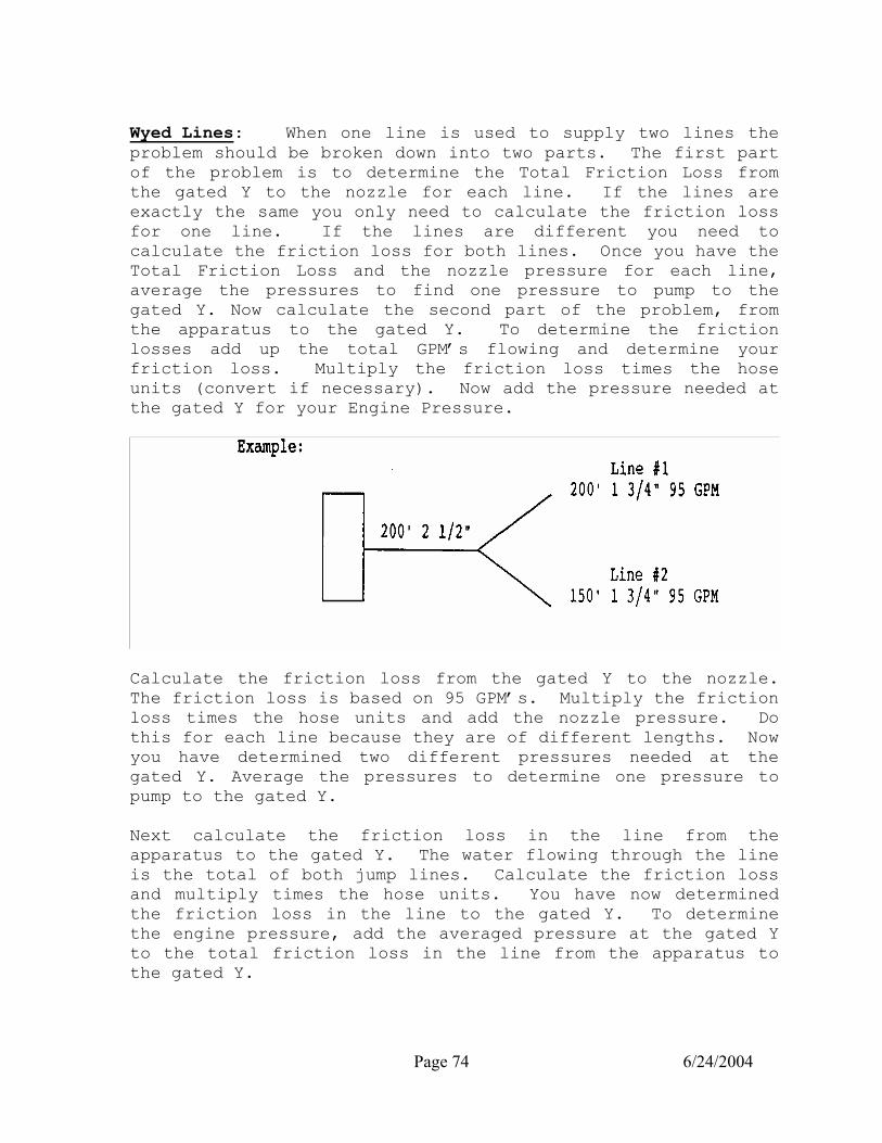
Page 74 6/24/2004
Wyed Lines: When one line is used to supply two lines the problem should be broken down into two parts. The first part of the problem is to determine the Total Friction Loss from the gated Y to the nozzle for each line. If the lines are exactly the same you only need to calculate the friction loss for one line. If the lines are different you need to calculate the friction loss for both lines. Once you have the Total Friction Loss and the nozzle pressure for each line, average the pressures to find one pressure to pump to the gated Y. Now calculate the second part of the problem, from the apparatus to the gated Y. To determine the friction losses add up the total GPM’s flowing and determine your friction loss. Multiply the friction loss times the hose units (convert if necessary). Now add the pressure needed at the gated Y for your Engine Pressure.
Calculate the friction loss from the gated Y to the nozzle. The friction loss is based on 95 GPM’s. Multiply the friction loss times the hose units and add the nozzle pressure. Do this for each line because they are of different lengths. Now you have determined two different pressures needed at the gated Y. Average the pressures to determine one pressure to pump to the gated Y. Next calculate the friction loss in the line from the apparatus to the gated Y. The water flowing through the line is the total of both jump lines. Calculate the friction loss and multiply times the hose units. You have now determined the friction loss in the line to the gated Y. To determine the engine pressure, add the averaged pressure at the gated Y to the total friction loss in the line from the apparatus to the gated Y.
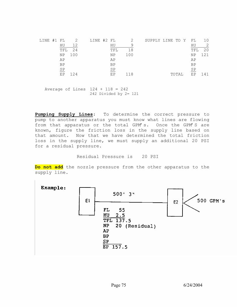
Page 75 6/24/2004
LINE #1 FL 2 HU 12 TFL 24 NP 100 AP BP SP EP 124
LINE #2 FL 2 HU 9 TFL 18 NP 100 AP BP SP EP 118
SUPPLY LINE TO Y FL 10 HU 2 TFL 20 NP 121 AP BP SP TOTAL EP 141
Average of Lines 124 + 118 = 242 242 Divided by 2= 121
Pumping Supply Lines: To determine the correct pressure to pump to another apparatus you must know what lines are flowing from that apparatus or the total GPM’s. Once the GPM’S are known, figure the friction loss in the supply line based on that amount. Now that we have determined the total friction loss in the supply line, we must supply an additional 20 PSI for a residual pressure. Residual Pressure is 20 PSI Do not add the nozzle pressure from the other apparatus to the supply line.

Page 76 6/24/2004
Pumping in Relay: When pumping a long hose lay and one pumper is not adequate to supply the total pressure, another pumper is needed in the hose layout. This pumper should spot 2/3 of the lay away from the original pumper (1/3 from the nozzle). The first pumper must then calculate the friction loss in the line to the relay pumper and add 20 PSI residual. This is similar to pumping a supply line. Example: 1500’ Hose Lay ____________________________________ 1000’ 500’ Pumping to Aerials: To determine the correct engine pressure For aerials you must know the following pressures needed at the base of the aerial:
Ladder Pipes 150 PSI L.T.I. 170 PSI Basket Aerials 170 PSI
Calculate the friction loss in the lines supplying the aerial and add the base pressure to determine the engine pressure. The base pressure takes into account the back pressure, nozzle pressure, and appliance pressure for the aerial. The base pressure may be adjusted for specific situations as determined by the operator.
E1
E2

Page 77 6/24/2004
5” Hose Rule of Hand: Five inch hose does not convert to 2 ½” hose; a separate rule of hand has been developed to assist the Driver-Engineer with calculating friction loss. Refer to the diagram below:
The numbers on the top of the fingers are the GPM’S IN 250 gallon increments beginning with 500 GPM’S. The numbers at the base of the fingers are the factors (2, 4, 7, 10, and 15). To calculate the friction loss, determine the gallons flowing through the hose and the finger that most closely represents the GPM’s. Go to the base of that finger and that factor is the friction loss for the hose. Do not multiply the first digit of the gallons times the factor. Once you have determined the correct factor, multiply the friction loss times the number of hose units. The rest of the formula remains the same for calculating the correct engine pressure.
Page 78 6/24/2004
Example: The friction loss in a 500 foot lay flowing 1000 GPM’S.
FL 7 HU 5 TFL 35
Hydrant selection is critical with five inch hose; do not expect more water than what is available from the hydrant as determined by a flow test. The static pressure will not indicate the GPM’s of the hydrant. Sample Hydraulic Problems: Sample hydraulic problems have been provided to assist you with practice in calculating friction loss and determining engine pressures. Work the problems to the best of your ability, and then check your answer with the answer sheet provided. Through practice and familiarization with working the problems your speed and confidence will increase. Follow these steps to solve the problem: 1. 2. 3. 4. 5. 6. 7. 8. 9. 10.
Determine the GPM’S flowing and the amount flowing through each line. Use the rule of hand to calculate the friction loss. Convert all the hose (except 5”) to 2 ½”. Average the hose lines. (if more than one line). Multiply Friction Loss x Hose Units for Total Friction Loss. Determine Nozzle Pressure. Determine Appliance Pressure and add to formula if necessary. Determine Back Pressure (if elevation of lines). Determine Standpipe or Sprinkler System Friction Loss. Add all factors to determine Engine Pressure.
If you have problems, make sure that you have determined the amount of water flowing through the line correctly and have averaged your hose. (Example; if you divided the GPM’s by two, the hose must also be divided by two). If you need any assistance or have any questions with a problem, please contact the Driver-Engineer Instructor for help or additional information.
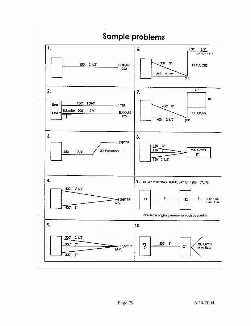
Page 79 6/24/2004

Page 80 6/24/2004
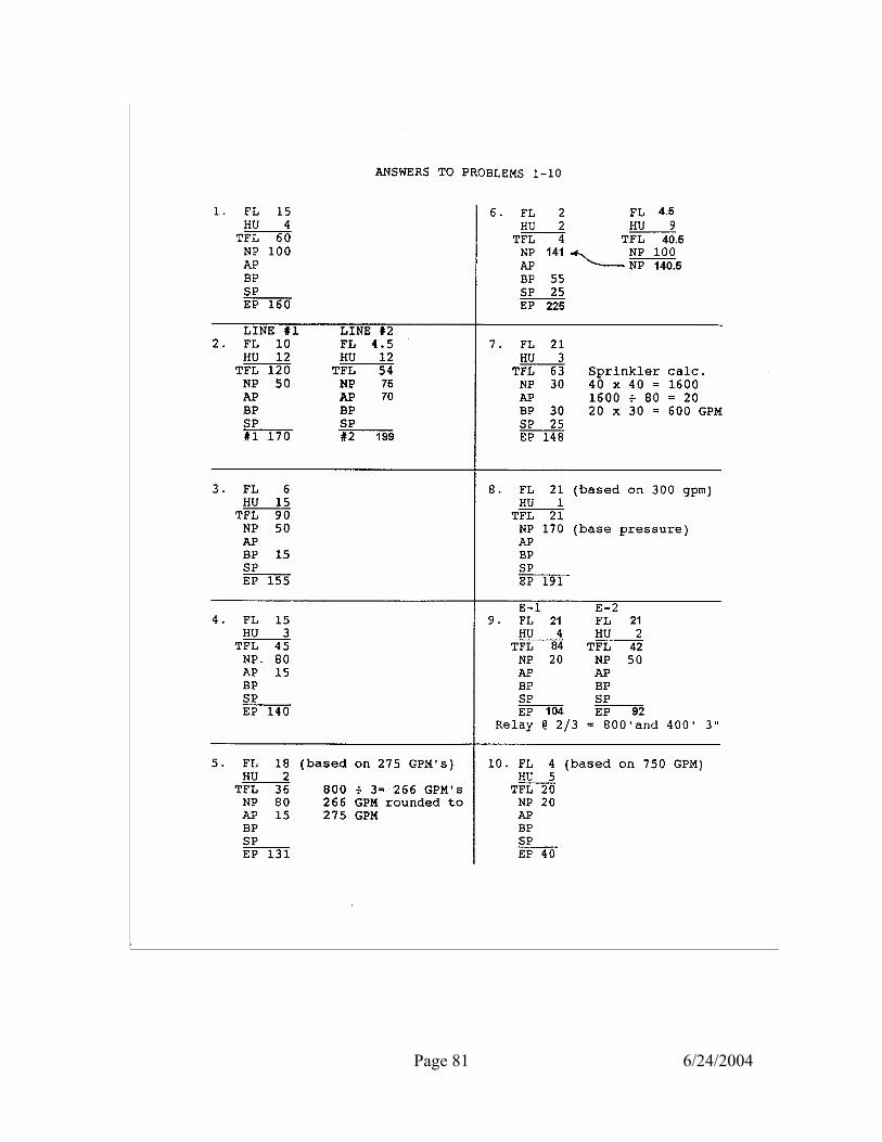
Page 81 6/24/2004

Page 82 6/24/2004

Page 83 6/24/2004
DRIVER ENGINEER CHECKOUT PROCEDURE
ALL CANDIDATES MUST HAVE SUCCESSFULLY COMPLETED THE RESERVE DRIVER-ENGINEER COURSE AND HAVE A VALID CLASS D LICENSE WITH “E” ENDORSEMENT. THE DRIVER-ENGINEER CHECKOUT CONSISTS OF FOUR PARTS: PART I- WRITTEN AND HYDRAULIC EXAM (each is exam graded separately) PART I –
A.
B.
WRITTEN AND HYDRAULILC EXAM Written Exam- 50 questions covering the following areas: Driver Information- Questions are taken from the O.P.M. and the E.O.M. (See study Reference sheet) and Driver-Engineer Handbook. Specifics of Apparatus- Questions on gauges, pump panel, engine and transmission information for your apparatus. Aerials will be questioned about aerial operations, load limits, etc. Hydraulic Exam- 10 hydraulic problems covering proper calculation of engine pressure. Problems will include pumping various hose layouts including 5” hose. Answers to problems must have all work shown and must be within 10 pounds + or – the correct answer (depending how the numbers were rounded off). Drivers assigned to an apparatus with a pump will be required to take the hydraulic portion of the exam.

Page 84 6/24/2004
PART II- PRACTICAL EXAM A. B. c.
Apparatus Inspection- All fluid levels, tires, and overall mechanical condition of apparatus and equipment will be checked. IF THE APPARATUS IS FOUND NOT READY FOR SERVICE OR IN AN UNSAFE CONDITION, AFTER THE CANDIDATE HAS STATED IT IS READY, THE TESTING WILL STOP AT THIS POINT AND A RE-TEST WILL BE SCHEDULED. THIS IS A PASS OR FAIL ITEM. Hydrant and Territory Notices-All current notices must be on the apparatus. THIS IS A PASS OR FAIL ITEM. Inventory-Candidate will be asked the location and use of 10 items taken from the apparatus inventory list. The candidate will know how to check and operate all items on the inventory list. Each item shall be worth 10 points.
PART III-PUMPING/DRAFTING AND/OR AERIAL OPEATIONS A.
Pumping/Drafting- At the F.D. shop drafting tank know proper procedures for drafting apparatus (Candidate will be in charge of drafting operations). Demonstrate proper setting of relief valve or pressure governor and pump operations. Know steps to follow if engine or pump overheats.
• Candidate will manually change from road to pump or engage pump and know manual overrides for gates (if applicable).
• At hydrant, pump various layouts (know what pressure to pump) and demonstrate proper pump operations.
• Pump from water tank prior to receiving hydrant supply.
• Refill water tank after water supply line is established.
• Know how to calculate available water from hydrant (static and residual pressure).
• Candidate will demonstrate proper gating of lines to pump two different pressures, and proper shutdown of lines.

Page 85 6/24/2004
B. Aerial Operations- Candidate will demonstrate the proper set up and positioning of apparatus to reach multiple victim locations.
• Proper sequence of operations. • Knowledge of aerial overrides and capacity of device. • Knowledge of tools and equipment.
Each skill will be evaluated and rated as: Satisfactory, Needs Improvement, or Unsatisfactory. If more than two skills are rated Needs Improvement or, any skill rated Unsatisfactory, the overall final rating will be Unsatisfactory.
PART IV- DRIVING EXAM A. Driving Exam- The exam consists of 4 exercises: Serpentine forward and reverse through 5 cones. Opposite Alley forward only. Straight Line forward and reverse. Alley Dock once from each direction. GRADING COMPLETE CHECKOUT
PART I. WRITTEN TEST HYDRAULIC PROBLEMS
PASSING GRADE 80%
PART II. PART III. PART IV
PRACTICAL TEST APPARATUS INSPECTION HYD. AND TERR. NOTICES INVENTORY TEST DRAFTING/PUMPING AND/OR AERIAL OPERATIONS DRIVING EXCERCISES
PASS OR FAIL PASS OR FAIL PASS OR FAIL SATISFACTORY OR UNSATISFACTORY PASS OR FAIL
EACH OF THE FOUR PARTS MUST BE PASSED. A RE-TEST WILL BE GIVEN WITHIN 30 DAYS FOR ANY PART FAILED. FAILURE OF THE RE-TEST WILL RESULT IN THE CANDIDATE BEING REMOVED FROM HIS/HER DRIVER-ENGINEER ASSIGNMENT.

Page 86 6/24/2004
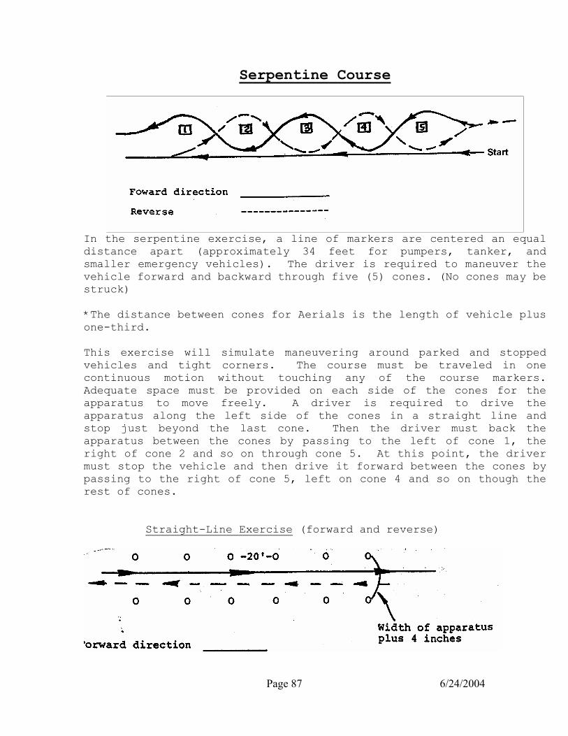
Page 87 6/24/2004
Serpentine Course
In the serpentine exercise, a line of markers are centered an equal distance apart (approximately 34 feet for pumpers, tanker, and smaller emergency vehicles). The driver is required to maneuver the vehicle forward and backward through five (5) cones. (No cones may be struck) *The distance between cones for Aerials is the length of vehicle plus one-third. This exercise will simulate maneuvering around parked and stopped vehicles and tight corners. The course must be traveled in one continuous motion without touching any of the course markers. Adequate space must be provided on each side of the cones for the apparatus to move freely. A driver is required to drive the apparatus along the left side of the cones in a straight line and stop just beyond the last cone. Then the driver must back the apparatus between the cones by passing to the left of cone 1, the right of cone 2 and so on through cone 5. At this point, the driver must stop the vehicle and then drive it forward between the cones by passing to the right of cone 5, left on cone 4 and so on though the rest of cones.
Straight-Line Exercise (forward and reverse)
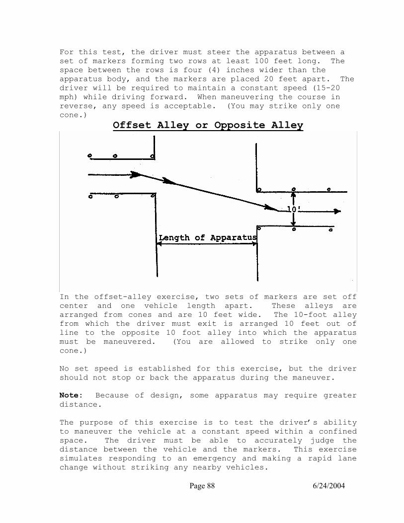
Page 88 6/24/2004
For this test, the driver must steer the apparatus between a set of markers forming two rows at least 100 feet long. The space between the rows is four (4) inches wider than the apparatus body, and the markers are placed 20 feet apart. The driver will be required to maintain a constant speed (15-20 mph) while driving forward. When maneuvering the course in reverse, any speed is acceptable. (You may strike only one cone.)
Offset Alley or Opposite Alley
In the offset-alley exercise, two sets of markers are set off center and one vehicle length apart. These alleys are arranged from cones and are 10 feet wide. The 10-foot alley from which the driver must exit is arranged 10 feet out of line to the opposite 10 foot alley into which the apparatus must be maneuvered. (You are allowed to strike only one cone.) No set speed is established for this exercise, but the driver should not stop or back the apparatus during the maneuver. Note: Because of design, some apparatus may require greater distance. The purpose of this exercise is to test the driver’s ability to maneuver the vehicle at a constant speed within a confined space. The driver must be able to accurately judge the distance between the vehicle and the markers. This exercise simulates responding to an emergency and making a rapid lane change without striking any nearby vehicles.
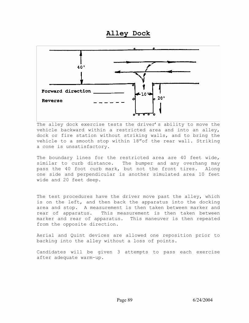
Page 89 6/24/2004
Alley Dock
The alley dock exercise tests the driver’s ability to move the vehicle backward within a restricted area and into an alley, dock or fire station without striking walls, and to bring the vehicle to a smooth stop within 18”of the rear wall. Striking a cone is unsatisfactory. The boundary lines for the restricted area are 40 feet wide, similar to curb distance. The bumper and any overhang may pass the 40 foot curb mark, but not the front tires. Along one side and perpendicular is another simulated area 10 feet wide and 20 feet deep. The test procedures have the driver move past the alley, which is on the left, and then back the apparatus into the docking area and stop. A measurement is then taken between marker and rear of apparatus. This measurement is then taken between marker and rear of apparatus. This maneuver is then repeated from the opposite direction. Aerial and Quint devices are allowed one reposition prior to backing into the alley without a loss of points. Candidates will be given 3 attempts to pass each exercise after adequate warm-up.
Page 90 6/24/2004
RESERVE DRIVER-ENGINEER COURSE REQUIREMENTS
The following requirements have been established for the reserve driver-engineer course: Hours of instruction: 48 hours Objective: The student will know how to care for and operate fire department apparatus safely and proficiently. The reserve driver-engineer student will be tested in four areas of knowledge and skill. 1. Written Exam Passing Grade 75% 2. Hydraulic Exam Passing Grade 75% 3. Practical Exam Pass Fail 4. Driving Exam Pass Fail All four areas must be passed to receive certification as a reserve driver-engineer. If a failure occurs in any of the four areas, one re-test will be allowed in the area(s) failed within 30 days. Written Exam: The student will be tested on information contained in the following references:
a. b.
E.O.M. study references O.P.M. study references
c. Driver-Engineer Handbook d. Handout study references e. Class notes from lecture

Page 91 6/24/2004
The student will: 1. 2. 3.
Identify driver responsibilities from department manuals. Identify items for a complete apparatus inspection Understand operation of diesel engines, fuel systems, air brakes, transmissions, and gauges.
4. 5. 6. 7. 8. 9.
Identify types of pumps, parts of a pump, pump operation, and pump theory. Identify pump gauges, pressure governor operation, relief valve, and pump connections. Identify pump problems, engine problems, and know procedures for correcting problems. Identify proper response to alarms, safe driving techniques, proper positioning, and State requirements for driving. Identify proper aerial operations and sequence of operations. Identify proper foam operations, types of foam, proper percentage of foam, and proper foam application.
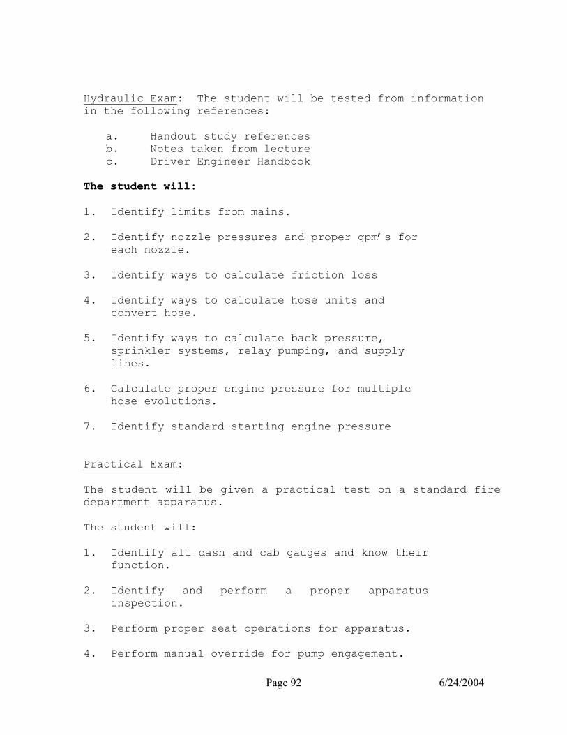
Page 92 6/24/2004
Hydraulic Exam: The student will be tested from information in the following references:
a. Handout study references b. Notes taken from lecture c. Driver Engineer Handbook
The student will: 1. 2. 3. 4. 5. 6.
Identify limits from mains. Identify nozzle pressures and proper gpm’s for each nozzle. Identify ways to calculate friction loss Identify ways to calculate hose units and convert hose. Identify ways to calculate back pressure, sprinkler systems, relay pumping, and supply lines. Calculate proper engine pressure for multiple hose evolutions.
7. Identify standard starting engine pressure Practical Exam: The student will be given a practical test on a standard fire department apparatus. The student will: 1. 2. 3. 4.
Identify all dash and cab gauges and know their function. Identify and perform a proper apparatus inspection. Perform proper seat operations for apparatus. Perform manual override for pump engagement.
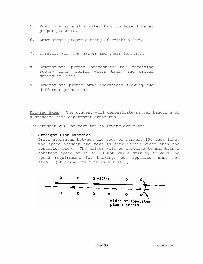
Page 93 6/24/2004
5. 6. 7. 8. 9.
Pump from apparatus water tank to hose line at proper pressure. Demonstrate proper setting of relief valve. Identify all pump gauges and their function. Demonstrate proper procedures for receiving supply line, refill water tank, and proper gating of lines. Demonstrate proper pump operations flowing two different pressures.
Driving Exam: The student will demonstrate proper handling of a standard fire department apparatus. The student will perform the following exercises: 1. Straight-Line Exercise.
Drive apparatus between two rows of markers 100 feet long. The space between the rows is four inches wider than the apparatus body. The driver will be required to maintain a constant speed of 15 to 20 mph while driving forward, no speed requirement for backing, but apparatus must not stop. (Striking one cone is allowed.)

Page 94 6/24/2004
Alley Dock Exercise: From each direction the driver must move past the alley and then back the apparatus into the dock area. The apparatus must stop within 18 inches but not touch the rear cones of the alley dock. Apparatus must not stop for credit to be given. The apparatus may not strike any cones. Three attempts will be given.

Page 95 6/24/2004
Miami Fire Dept. CDL Brake Test and Leak Test
Commercial Drivers License brake test
The CDL brake test is a certified commercial brake test that checks the integrity of the air brake system for any possible leaks that may occur. It also checks the emergency component of the air brake system. Below are two separate tests needed to perform the CDL brake test. These two tests should be performed daily.
Parking Brake/Service Brake Test:
Warning : The apparatus must be on LEVEL GROUND! The first test is to check the integrity of the apparatus parking brake and service brake system. 1. Start the apparatus and apply the Parking Brake. Place the apparatus in drive. The apparatus should not move. . If so, immediately put the apparatus out of service and notify the fire department shop. 2. While the apparatus is running in drive apply pressure to the Service Brake and release the Parking Brake. The apparatus should not move. . If so, immediately put the apparatus out of service and notify the fire department shop. . .

Page 96 6/24/2004
Leak Test
The second test is the leak test that checks 3 different areas of the braking system. These are the “holding pressure” leak test, the “warning indicators” on the dash and the ability of the “parking brake” to engage automatically. 1 Place apparatus on LEVEL GROUND. 2 Shut off the apparatus and leave ignition switch turned on. (The Parking Brake should still be off). The apparatus SHOULD NOT MOVE. If so, reposition the apparatus to level ground. 3 Apply firm pressure to the service brake and hold down for 1 minute. There should be no more than 3 PSI loss of air pressure in. If so, notify the fire department garage. 4 If no loss in air pressure, continue to “pat down” the service brake until you see and hear the audio and visual warning indicators come on (at approximately 80-85 PSI) If not, notify the fire department garage. 5 Continue “patting down” the service brake until the parking brake AUTOMATICALLY engages (at approximately 20- 45 PSI). If not immediately put the apparatus out of service and notify the fire department shop. 6 Start the apparatus and slightly accelerate the engine to refill the air brake system. The audio and visual air pressure indicators should go off at about 80-85 PSI at approximately 120-125 psi the air dryer should discharge (indicated by a burst of air) This completes the Miami Fire Department’s CDL brake test!
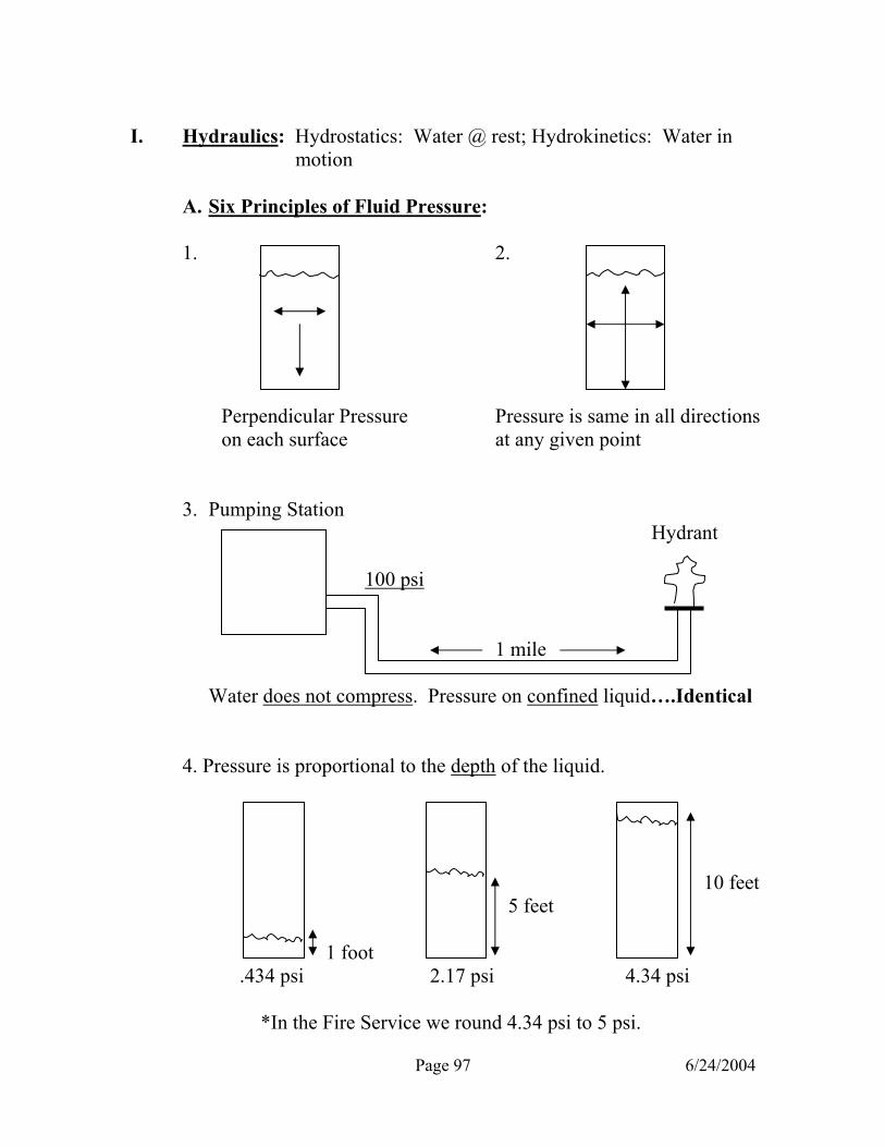
Page 97 6/24/2004
I. Hydraulics: Hydrostatics: Water @ rest; Hydrokinetics: Water in
motion A. Six Principles of Fluid Pressure: 1. 2. Perpendicular Pressure Pressure is same in all directions on each surface at any given point 3. Pumping Station Hydrant 100 psi 1 mile Water does not compress. Pressure on confined liquid….Identical 4. Pressure is proportional to the depth of the liquid. 10 feet 5 feet 1 foot .434 psi 2.17 psi 4.34 psi *In the Fire Service we round 4.34 psi to 5 psi.

Page 98 6/24/2004
5. Pressure is proportional to the density of the liquid. (Hg 13x) 10 feet of water .769 feet (Hg) of mercury 4.34 psi 4.34 psi 6. Liquid pressure at the bottom of a container is not affected by the size and shape of the container 10’ 10’ 10’ 4.34 lbs/in. sq. 4.34 lbs/in. sq. 4.34 lbs/in. sq. B. Friction Loss: (2 types of water flow) 1. Laminar flow- At low velocities, water is in layers. Less than 100
GPM’s in 2 ½” hose. Inject dye
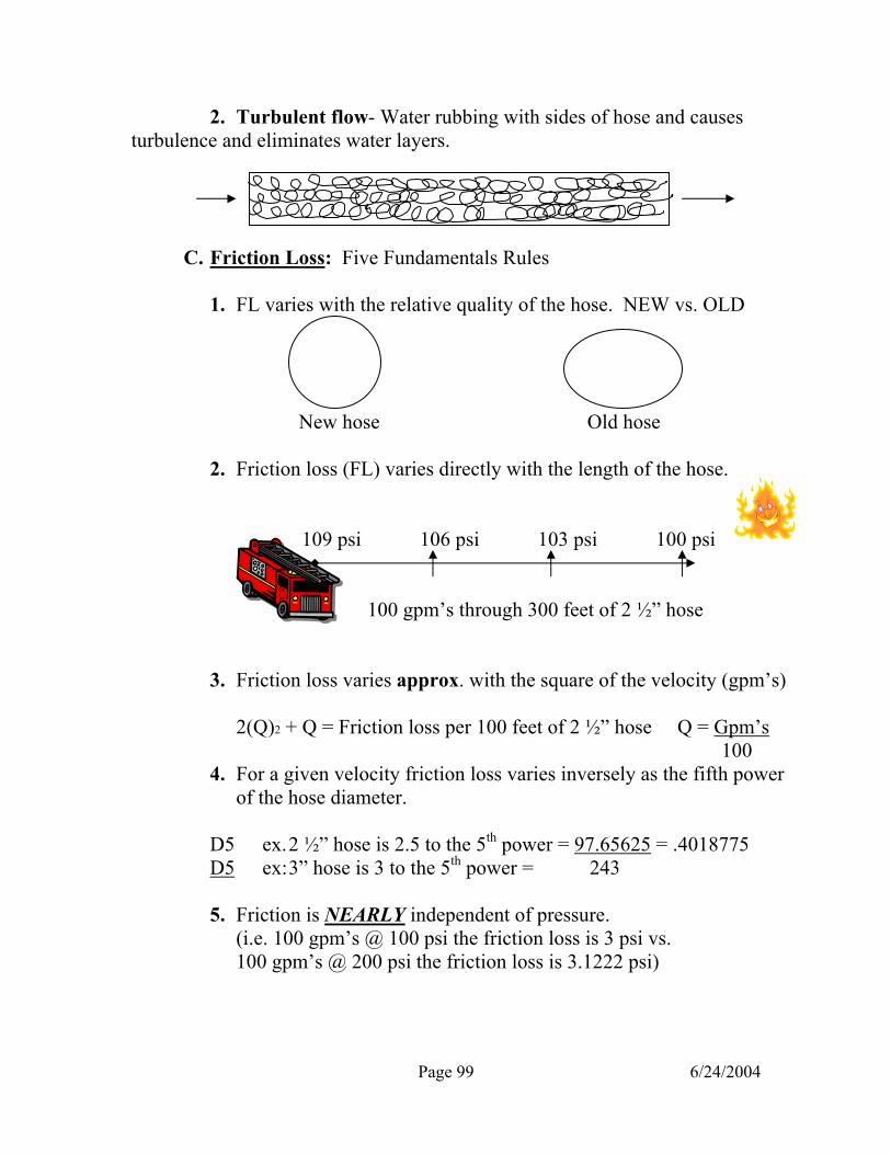
Page 99 6/24/2004
2. Turbulent flow- Water rubbing with sides of hose and causes turbulence and eliminates water layers. C. Friction Loss: Five Fundamentals Rules 1. FL varies with the relative quality of the hose. NEW vs. OLD New hose Old hose 2. Friction loss (FL) varies directly with the length of the hose. 109 psi 106 psi 103 psi 100 psi 100 gpm’s through 300 feet of 2 ½” hose 3. Friction loss varies approx. with the square of the velocity (gpm’s) 2(Q)2 + Q = Friction loss per 100 feet of 2 ½” hose Q = Gpm’s 100 4. For a given velocity friction loss varies inversely as the fifth power
of the hose diameter. D5 ex. 2 ½” hose is 2.5 to the 5th power = 97.65625 = .4018775 D5 ex: 3” hose is 3 to the 5th power = 243
5. Friction is NEARLY independent of pressure. (i.e. 100 gpm’s @ 100 psi the friction loss is 3 psi vs. 100 gpm’s @ 200 psi the friction loss is 3.1222 psi)

Page 100 6/24/2004
Fire Service Hydraulics Best Ways to Reduce Friction Loss: 1. Increase the size of the hose 2. Reduce the length of the hose 3. Reduce the gallons flowing 4. Buy new hose 5. Add another line most easily achieved
Standard Nozzle Pressure (SNP) All Fog All Fog All Solid All Solid Hand lines Master Streams Tip Hand lines Master Streams *100 psi **100 psi 50 psi 80 psi Exception:* Elkhart 125 nozzle with deflector plate when it reads 125/75. 75 psi Exception: ** Akromatic 2000 nozzle (Quint 4) 80 psi. 200 300 400 750 1000 1250 GPM’S 500 GPM’S 1500 100 500 5 7 9 4 7 10 11 15 3 FACTORS 2 FACTORS 2 ½” Hose 5” Hose Hand Formula Hand Formula *NOTE: 5” hose line should only be used as a SUPPLY LINE, not a pressure line!

Page 101 6/24/2004
Friction Loss Less than 100 gpm’s is 2 300 21 100 gpm’s 3 325 24 125 4.5 350 28 150 6 375 32 175 8 400 36 200 10 425 40 225 12.5 450 45 250 15 475 50 275 18 500 55 To figure out the friction loss correctly, all hose units must be converted to 2 ½” hose.
Multipliers 1 ¾” hose X 6 2 ½” hose X 1 3” hose X .5 or ½ All hydraulic equations to figure out engine pressure must use the following formula. FL =Friction loss x HU =Hose units TFL =Total friction loss NP =Nozzle pressure BP =Back pressure AP =Appliance pressure SP =Standpipe or Sprinkler system EP =Engine Pressure Standard Starting Engine Pressure: Friction loss on Appliances: Multiversals 100 psi Multiversals/Deck Gun 15 psi Supply line 100 psi Sprinkler/Standpipe 25 psi Sprinkler 100 psi In-Line Foam Eductor 70 psi All hand lines 125 psi Standpipe 150 psi Back pressure: Ladder pipe 150 psi .434 (.5) per foot LTI Aerial 170 psi 5 psi per floor (10 feet) AFFF foam lines 200 psi Standpipe System: Minus 1 floor
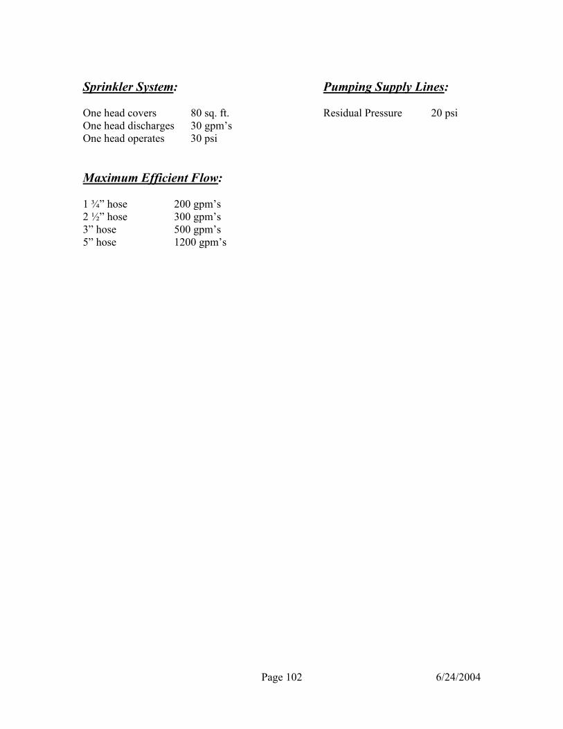
Page 102 6/24/2004
Sprinkler System: Pumping Supply Lines: One head covers 80 sq. ft. Residual Pressure 20 psi One head discharges 30 gpm’s One head operates 30 psi Maximum Efficient Flow: 1 ¾” hose 200 gpm’s 2 ½” hose 300 gpm’s 3” hose 500 gpm’s 5” hose 1200 gpm’s