drive wheel pin - society of professional locksmiths
TRANSCRIPT

PAGE
Drive Wheel Pin—A Vital Link 1 Identification of Safes 2 ABC's of Combination Lock Changing
Rules of Rotation 8 Hand Change Locks 9 Direction of Rotation 12 Key Change Locks 13 Reasons for Failure to Open 16
General Safe Techniques Angle Drilling 19 Correcting Drilled Holes 20 Vibrating to Free Jammed Tumblers 21
Safe Combination Locks Nomenclature—Determining Lock Style 23 Movable Flys or Stationary Pins 24 OB, OBB and Mosler 10 Locks 24
Types of Safe Locking Mechanisms Direct-into-wheel (straight and force-up lever) 28 Gravity Drop Lever 29 Standard Combination 29
Detection and Try-out Methods Explanation of Techniques 33 Lockouts on File Cabinets 34
Servicing "Old Line" Iron and Modern Cabinet-Type Safes 39 Servicing Burglarized Safes
Neutralizing Explosives 44 Methods of Working Spindle 46 Knocked-Off Dials and Handles 47
Herring-Hall-Marvin Safes 49 Servicing Diebold Safes 55 Meilink Safes 62 Mosler Safes 64 Techniques of Safe Servicing (York, National, Protectall,
Pittsburgh Safes) 70 Round Door Money Chests 76 Vault Doors—Grout and Non-Grout Types 82 Exploded Lock Views (Sargent & Greenleaf, Inc.)
T MP Series Combination Lock 86 R Series Combination Lock 86 6 7 0 9 Series Combination Lock 88
How to Order a Safe Lock 89
Published by
DrIVE WHEEL PIN
One of the most vital links between the combination dial and the wheel pack is the pin in the drive wheel. It is very small, and yet it does a mountainous job. If this little pin, for any reason, loses its connection with the number 1 wheel, the safe will not open.
This pin or the corresponding fly in the wheel sometimes wear down and very often snap off and break. Although very small, either of these two parts is adequately strong enough to do the job it was designed to do. The reasons they wear or break are related to various factors. Misuse and abuse are key factors. Most people don't realize how destructive spinning or snapping the combination dial can be to the lock. This practice continuously followed will ultimately cause the drive wheel pin or the fly to break off.
Another factor not related to abuse is the absence of periodical service and lubrication of a combination lock. If the wheel pack begins to turn very hard because of wear and dryness, it requires more turning pressure to move the wheels around.
-A VITAL LINK
All the pressure is on the two pressure points—the drive wheel pin and the fly. If the pressure becomes too great and is allowed to continue for any length of time, ultimately one of the two connecting parts will snap. If connection is lost between the drive wheel and the wheel pack because of a broken fly or drive wheel pin, the safe will not open. The only way to open this type of lockout is by penetration.
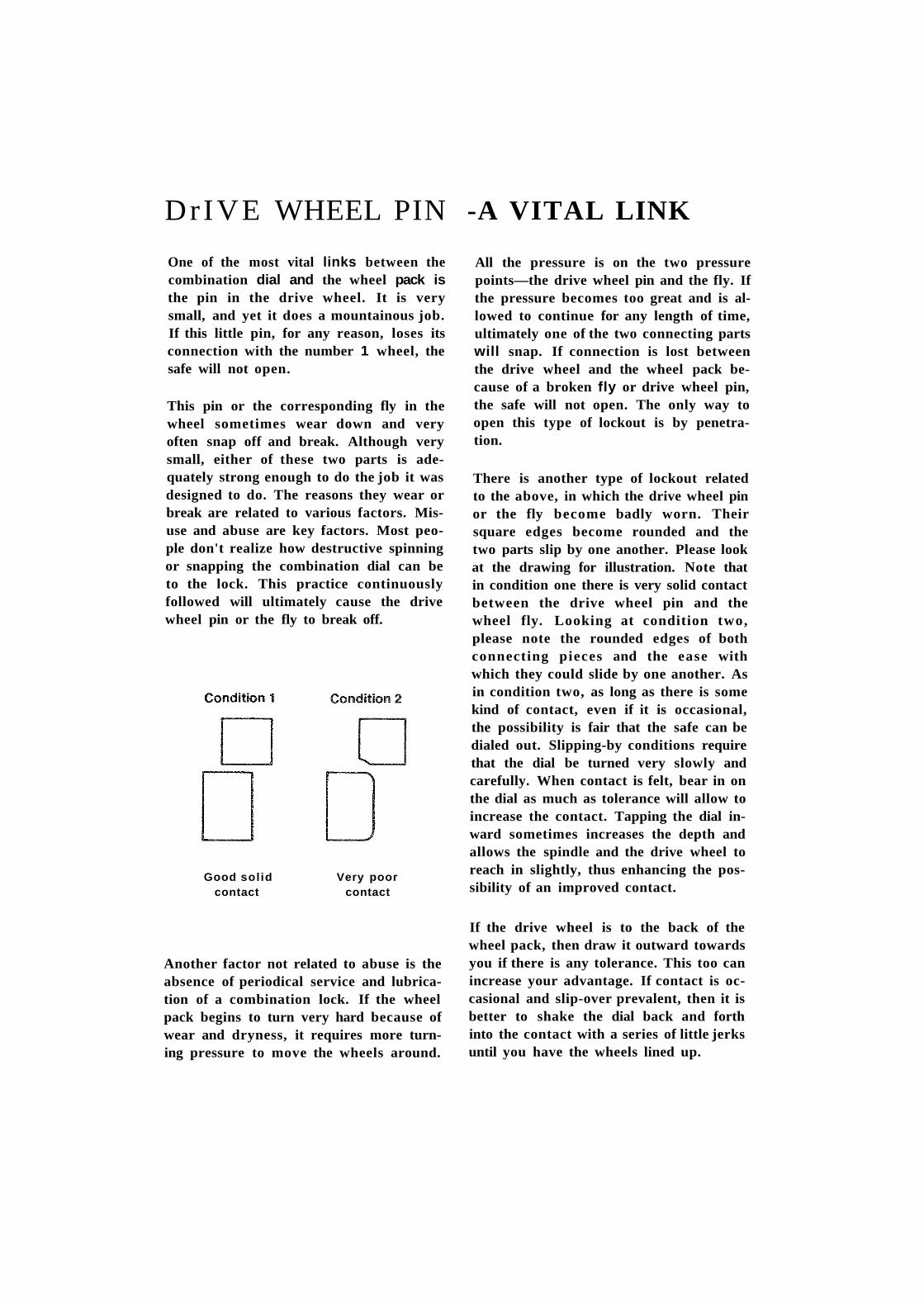
There is another type of lockout related to the above, in which the drive wheel pin or the fly become badly worn. Their square edges become rounded and the two parts slip by one another. Please look at the drawing for illustration. Note that in condition one there is very solid contact between the drive wheel pin and the wheel fly. Looking at condition two, please note the rounded edges of both connecting pieces and the ease with which they could slide by one another. As in condition two, as long as there is some kind of contact, even if it is occasional, the possibility is fair that the safe can be dialed out. Slipping-by conditions require that the dial be turned very slowly and carefully. When contact is felt, bear in on the dial as much as tolerance will allow to increase the contact. Tapping the dial inward sometimes increases the depth and allows the spindle and the drive wheel to reach in slightly, thus enhancing the possibility of an improved contact.
If the drive wheel is to the back of the wheel pack, then draw it outward towards you if there is any tolerance. This too can increase your advantage. If contact is occasional and slip-over prevalent, then it is better to shake the dial back and forth into the contact with a series of little jerks until you have the wheels lined up.
Good solid Very poor contact contact

Many of the locksmiths I have talked with have expressed a strong desire to add safe servicing and repairing to their regular line, but for want of further knowledge of same have cast the idea aside. One of the major drawbacks seems to be the fact that the different makes of safes are difficult to distinguish. To be able to tell one make of safe from another when they all look so very much alike and have the same general appearance is quite an art. In the past 150 years almost as many different makes of safes have made their appearance on the American market and, generally speaking, they are all very much alike since most of them have a combination dial, a bolt handle, wheels and hinge tips. And, for the most part they all look heavy! Yes, this general description could fit almost any make of safe ever produced. But, it is quite possible and very easy to distinguish one from the other, once you have acquired the know-how.
To become an experienced craftsman in the art of opening and repairing safes requires first that you be able to identify a particular make of safe. This is especially true in the practise of opening safes since each safe is approached differently and requires a different method of opening. Many safes are similar in design and may require the same approach in opening but unless you are able to distinguish the make you will have difficulty in applying your knowledge.
Safe recognition is vitally important for once you know who made it, coupled with that all important experience of course, then you will automatically know how to approach it. If each safe were identified by large gold letters, safe recognition would be comparatively easy. However, because of age and deterioration and in most cases the fact that a safe has been re-painted many times, maker's names are usually never persent.
How can we recognize a particular make of safe? How can we tell, for instance, that one safe is a "Mosler" and another is a "Hall". There are many peculiar identifying characteristics present on each and every safe to enable us to distinguish it. Dials, handles, body and door corners, wheels and castors will aid you in determining one safe from another.
The first step you take in safe recognition is to look for the maker's name. If the original finish has been re-painted (which is most likely the case) the name may show through the repainted surface in an embossed manner, like raised letters which can be seen by looking sideways across the face of the safe. Very often the name can be found on the face of the combination dial hub. Usually, names are present here, BUT DO NOT CONFUSE THE MAKER OF THE LOCK WITH THE MAKER OF THE SAFE! Many safes have been referred to

as a Yale safe or a Sargent when actually there is no such make. Safe manufacturers do not always use their own locks and only in such cases will the maker's name mean anything to you.
For the present, I believe, the most practical approach to the subject of safe identification is to limit ourselves to the safes most commonly used and seen on the market today. I do not believe it necessary to be concerned about new style safes because they are distinctive in styling and design. It is the older styles dating back to 30 to 50 years that most locksmiths have difficulty identifying.
Since the largest builder of safes and vaults today is the Mosler Safe Company, let us start here. An old Mosler safe can be identified easily by its rounded body corners. (See Figure 1) , square cornered door and drop type handle. Two types of combination locks were used on this type of safe depending on whether or not it was the heavy wall type with the step down door or the medi-um thick wall type. By applying a slight pressure on the bolt handle it is possible to distinguish which style it is. The heavy walled safe uses the common straight bolt in box combination lock with the cam locking effect striking the top of the bolt in the locked position. The lighter walled Mosler safe uses a push up dog type combination in which the dog is pushed up into the combination tumblers. You will notice on applying slight pressure on this style of locking mechanism that the action or pressure of the dog on the tumblers prevents the combination from turning freely. The combination dial of the heavy wall safe will turn freely whether pressure is applied or not.
Modern Mosler safes, commonly referred to as "cabinet type" have three distinctive styles, depending on whether it is an A label, В label or С label safe.
The one thing that is common on all three, however, is the style of the bolt handle that is used. (See Figure No. 2).
Another very common make of sale is the Diebold. Diebold characteristics are quite the opposite in design to Mosler. Instead of the rounded body corners and the square cornered door that Mosler uses, Dieboid safes have square body corners and rounded door
corners. (See Figure No. 3). Diebold also has two distinct styles of
Fig 2 Mosler (modern)

safes: 1—The heavy walled safe designed for severe fire hazard; 2— The thinner walled safe designed for moderate-to-light fire exposure. On each of these two safes different styles of locks were used. Like Mosler, the thick walled safe uses a common straight bolt in box type combination lock, and the lighter walled safe uses the push up dog type lock, (See Figure No. 4) which, when pressure is applied to the handle, affects the free spinning of the combination dial. A common Diebold drop type bolt handle is used on both heavy and light walled safes. (See Figure No. 5).
Some safes in the field today use "one knob control" in locking and unlocking both combination and bolt mechanism. Of these, the one that you will probably run across most frequently is the Victor safe. The single knob control can be easily identified as a Victor safe if the dial looks like that shown on Figure No. 6. Younger model Victor safes use a separate bolt control handle. The style of dial used is similar to the old style safes with the exception that the two lugs protruding from the hub of combination dial are not used. Otherwise, the dial is identical.
While we are in the catagory of safes with single knob control characteristics, there is another safe that deserves mention: the Reliable safe. This one has a combination dial to operate the lock and also has a bolt operating handle. The dial and the bolt handle are in one integral unit, but operate independently of each other. As you can see in Figure No. 7, the handle is just below the combination dial and the connecting sleeve of this handle tits snugly underneath or in back of the dial.
A neat side rim encircles the two parts. The handle on a Reliable safe is free spinning when the safe is locked, but as you line up the combination tumblers with the combination dial, a dog drops into place. A

ratchet arrangement within the lock also falls into a slotted cam attached to the handle which allows it to be engaged and operate the bolt mechanism. This type of lock is very similar to the lock used on a Victor safe.
Hall's patented safes are still very commonly used today. Just recently the old Hall safe works have been re-activated by a division of the Herring-Hall-Marvin Safe Co. Very prominent identification characteristics are the hinge tips, the combination dial and the ornamental style of body corners. The door of a Hall safe has square corners as do the body frame or architrave, but beyond this, the body is rounded in an ornamental style as show in Figure No. 8. The hinge tip of a Hall safe is
a definite clue. (See Figure Mo. 9.) A Hall safe does NOT resemble a Herring-Hall-Marvin safe, its first cousin.
Herring-Hall-Marvin (H.H.M.) safes can be identified, first of all, by the rather stout hinge tip. See Figure No. 10. The bolt operating handle is unlike any safe handle ever used on any make of safe. It measures approximately 6 1/2" from top of knob to lower tip of handle grip. (See Figure No. 11.) The handle is removable from the outside because it is held in
place by a screw. The hub of handle is square with all the corners shaved off. Besides this large drop type handle, another style was also used. This was a neater T handle which is also removable from the outside. (See Figure No. 12). Herring-Hall - Marvin safes use their own locks as does the Hall safe. B o t h have h a r d e n e d steel plates to resist drilling. The l o c k i n g mechanism on the Hall safe consists of a set of three tumblers and a drive wheel w h i c h also acts as a tumbler. When all tumblers are in line, a slide

attached to t h e bolt bar fits into the aligned slots and b o l t s are drawn back. (See F i g u r e No. 13.) The Herring-Hall-Marvin safe uses a push-up d o g type lock, whereby, when all tumblers are in alignment, a slide at
tached to the main bolt bar bears into bellcrank which in turn is pressed up into the slots of the combination tumblers. See Figure No. 14.
Carey safes have long since been discontinued but there are still enough of them in use today to be concerned about them. A Carey safe employs the simple method of locking shown back in Figure No. 13, and similar to the Hall safe described above. Like the Hall safe a Carey safe also has a hardened drill-proof plate. It can be identified by a drop handle with rounded graceful tear drop handle grip and a camel lump type hinge. (See Figure No. 16.)
The Syracuse safe was at one time a very popular make and today many of these are in use. The body corners of a Syracuse safe are rounded and the door is square. Large heavy castors and wheels with holes were used. The inside corners of the door were
rounded as were the corners of the d o o r jam. (See Figure No. 17) A Syracuse safe always uses T handles.
The Baum safe is also widely used today and can be identified by both rounded body corners and rounded door corners. See Figure No. 18. Fig 18 Baum
Fig 17 Syracuse
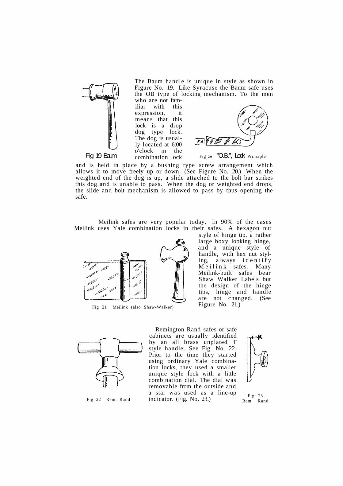
The Baum handle is unique in style as shown in Figure No. 19. Like Syracuse the Baum safe uses the OB type of locking mechanism. To the men who are not familiar with this expression, it means that this lock is a drop dog type lock. The dog is usually located at 6:00 o'clock in the combination lock
and is held in place by a bushing type screw arrangement which allows it to move freely up or down. (See Figure No. 20.) When the weighted end of the dog is up, a slide attached to the bolt bar strikes this dog and is unable to pass. When the dog or weighted end drops, the slide and bolt mechanism is allowed to pass by thus opening the safe.
Meilink safes are very popular today. In 90% of the cases Meilink uses Yale combination locks in their safes. A hexagon nut
style of hinge tip, a rather large boxy looking hinge, and a unique style of handle, with hex nut styling, always i d e n t i f y M e i l i n k safes. Many Meilink-built safes bear Shaw Walker Labels but the design of the hinge tips, hinge and handle are not changed. (See Figure No. 21.)
Remington Rand safes or safe cabinets are usually identified by an all brass unplated T style handle. See Fig. No. 22. Prior to the time they started using ordinary Yale combination locks, they used a smaller unique style lock with a little combination dial. The dial was removable from the outside and a star was used as a line-up indicator. (Fig. No. 23.)
Fig 19 Baum Fig 2 0 "O.B.", Lock Principle
Fig 21 Meilink (also Shaw-Walker)
Fig 22 Rem. Rand Fig 23
Rem. Rand

A B C' s of combination lock changing
R U L E S O F R O T A T I O N D I R E C T I O N O F R O T A T I O N
H A N D C H A N G E L O C K S K E Y C H A N G E L O C K S
R E A S O N S F O R F A I L U R E T O O P E N
There are two classes of combination locks with which you must become familiar to become competent in the art of changing combinations: the Hand Change Type and the Key Change Type. Before you attempt to change the combination of either of these types, you should first understand the fundamental theory and mechanical operations of the locks themselves. Such knowledge makes combination changing much simpler. Bear in mind that changing combinations is a very tricky maneuver; a small mistake can be extremely costly, even to the point of a lock-out.
Rules of Rotation
As you know, dialing a combination is merely rotating the tumblers to line up their gates or slots at the drop-in point in line with the locking dog. It is therefore important to know the order in which the tumblers rotate when turning the dial so that you can set the combination correctly.
Usually the movement of the dial controls the tumblers by means of a drive wheel. This drive wheel may be in the front or the r ea r depending upon the construction of the lock.
Front drives pick up the tumbler NEAREST the dial AFTER the first complete turn of the dial knob; then the next tumbler AFTER the second complete turn of the dial IN THE SAME DIRECTION; and finally the tumbler FURTHEST away from the dial face AFTER the third complete turn of the dial IN THE SAME DIRECTION.
Rear drives work in the opposite manner. AFTER the first complete rotation of the dial, the tumbler FURTHEST away from the dial face is picked up; then, AFTER the second complete rotation IN THE SAME DIRECTION, the middle tumbler is picked up; and finally, AFTER the third complete rotation of the dial IN THE SAME DIRECTION, the tumbler NEAREST the dial face is picked up.
Locks which have four tumblers perform in the same manner with the addition that one extra turn IN THE SAME DIRECTION is required to pick up the extra tumbler. Once all the tumblers are picked up, they will continue to revolve as long as the dial is rotated in the same direction.

When the direction of the dial rotation is reversed, ALL the tumblers will stop revolving. However, after the first complete rotation of the dial IN THE OPPOSITE DIRECTION, the "pick up" process begins again. One of the tumblers will be picked up by the drive and begin revolving. With each succeeding rotation of the dial, another tumbler will be picked up until all are revolving.
The action of the tumblers disengaging from the drive mechanism when the dial rotation is reversed and being picked up one at a time with each succeeding rotation, occurs in either front or rear drive locks. It is fundamental of every combination lock. It enables you to rotate the tumblers individually to the drop in point without disturbing the setting of tumblers already in alignment.
Another principle of combination locks is that the FIRST number dialed corresponds to the LAST tumbler revolved by the drive mechanism and the LAST number of the combination corresponds to the FIRST tumbler revolved by the drive mechanism. The middle numbers of the combination depend on the number of the tumblers in the lock, but, they too, correspond to the combination numbers in the reverse order of their pick-up by the drive mechanism.
In three tumbler locks having a front drive mechanism, the tumbler FURTHEST away from the dial face corresponds to the FIRST number of the combination. The middle tumbler corresponds to the second combination number, and the tumbler NEAREST the dial face corresponds to the last combination number. The same sequence holds true for a front drive four tumbler lock, with the addition that the tumbler nearest the dial face corresponds to the last combination number.
In three tumbler locks having a rear drive mechanism, the reverse relationship is true. The tumbler NEAREST the dial face corresponds to the FIRST number of the combination. The middle tumbler corresponds to the second combination number; and the tumbler FURTHEST away from the dial face corresponds to the LAST combination number. For a four tumbler lock, the sequence is the same with the addition that the tumbler furthest away from the dial face corresponds to the last combination number.
Hand Change Locks
Once the relationship between the tumblers and the numbers of the combination is understood, we can proceed with the methods for changing the combination of hand and key change type locks.
Let us begin with the most popular type — the hand change combination lock which has tumblers with the PUNCH-OUT CENTER. This type is found on just about any make of safe ever made. Figure 1 shows two views of the tumblers of this lock; "A" is a front view of the tumbler showing the center in place, and "B" shows the center removed.

All hand change locks have a CURB on which the discs or tumblers are held in place. The curb is illustrated in Figure 2.
You will find that the number of tumblers on the post may vary according to the style of the lock, but this however, does not alter the procedure of changing combinations.
To change the combination, first remove the curb and its attached tumblers, from the lock body on the safe door. Sometimes the curb is mounted on the panel on the back of the door. Or, you may have to
remove the plate or panel covering an inspection hole that is positioned right over the lock. In other cases, the curb is attached to the, back cover of the lock. Usually, removal of the fastening screws removes the curb from the lock body.
Place the curb on the workbench with the tumblers UP. The tumblers are held to the post by a brass snap ring which must be removed. A screwdriver or knifeblade can be used to pry up this ring. (See figure 3.)
Then, remove the tumblers and spacer washers, one at a time, placing them in a row according to the order in which they are removed from the curb post. The order of removal should be: Brass snap ring, tumbler, washer, tumbler, washer, etc. DON'T MIX THEM UP! This is very important; the lock will not work if they are put back in any other order.
Now, examine one of the tumblers. Notice that this type consists of three components: the OUTER RING, which has a series

of numbers; an inner geared ring called the HUB which fits into the outer ring; and the FLY, the small circular washer with a small projection or lug, which is attached to the hub. The center hub will separate from the outer ring by merely applying slight pressure on it with your thumbs. (Fig. 1B)
Notice that the hub has an engraved INDICATOR LINE. When this line is set to a number on the outer ring, it determines the combination number for that tumbler.
Before you begin to rearrange the hubs in the tumblers, write down the new combination you are going to set. Determine the tumblers which correspond to the numbers by following the rules of rotation we discussed before.
To illustrate the changing procedure, let us assume you are working with a three tumbler lock with a front drive mechanism, on which you want to set the new combination of 10, 30 and 50. Following the rules of rotation, you know that the first number of the new combination, No. 10, corresponds to tumbler furthest away from the dial face, or the one which was removed last from the post. Remove the hub from the center of this tumbler and set the indicator line at No. 10. Snap the two parts together and place the tumbler back in its position on the workbench.
The second number of the new combination, No. 30, corresponds to the middle tumbler, or the second one which was removed from the post. Push out the hub from the center of this tumbler and set its line on No. 30. Snap the hub back in place and lay the tumbler back in its former position on the table.
The third number of the combination, No. 50, corresponds to the tumbler nearest the dial face, or the one which you removed from the post first. Remove the hub from the outer ring and place the indicator line on No. 50. Snap the two together and lay the tumbler back in its former position on the workbench.
The new combination of Nos. 10, 30, and 50 has now been set. Check the tumblers to see that the hubs are secure in the outer rings and that the fly is positioned in the open arc of the hub. Clean each tumbler and apply a small amount of graphite to the rubbing surfaces of the tumblers and washers. Now, replace the tumblers and the washers on the curb post, reversing their order of removal, that is, the last one removed is the first one replaced, etc. BE SURE YOU START WITH THE LAST ONE REMOVED. Next, replace the snap ring in the groove at the top of the post. Insert the curb and tumblers back into the lock body and fasten with the screws.
CAUTION ! ! ! NEVER LOCK THE SAFE DOOR BEFORE YOU HAVE TRIED THE NEW COMBINATION AT LEAST THREE OR FOUR TIMES!

Direction of Rotation
The direction of turning a combination dial depends on the action of the locking dog. Some dogs merely drop into the lined up tumbler slots, permitting the bolt to be moved by a separate handle. Others drop into a hooked slot in the drive wheel which then has to be turned to retract the locking bolt. The important thing to remember is this: LOOK AT THE LOCK MECHANISM AND DETERMINE THE DIRECTION YOUR LAST TURN SHOULD BE. If, for instance, your drive wheel retracts the bolt by turning to the right, your last combination number should be approached to the left, the next to the last should be right, etc, etc.
If the lock does not open every time, retract your steps, double checking the tumbler positions, number selection, and the sequence of numbers.
There are two other versions of the tumblers used in hand change combination locks: the pin in hole type and the screw-in-hole type. Figure 4A shows the pin-in-hole tumbler with the pin driver in place and Figure 4B shows the pin driver itself. Tumblers of these types consist of two parts: the tumbler and the pin driver or a screw.
The tumblers are of a one piece construction and are provided with a series of holes around the outer edge. Although in most cases the holes are numbered, you may find some tumblers without any marks at all. The pin driver is nothing more than a circular washer with a hooked lug which fits into the holes of the tumbler, thus determining the position of the combination number. The tumblers in some combination locks have screws instead of a pindriver, which performs the same function as the lug on the pin driver.
To change a combination on this type of lock, remove the curb and tumblers from the lock body, placing them on the table with the tumblers up. Remove the snap ring, the tumblers and the washers, placing them in a line according to their order of removal. Working with one tumbler at a time, place the lug of the pin driver or the screw in the hole which corresponds with the numbers of the new combina-
Other Hand Change Tumblers

tion. REMEMBER! The same relation between the tumblers and numbers also holds true in these locks. On these locks, it is advisable to keep at least five numbers away from the tumbler slot on either side and to keep at least ten numbers difference between tumblers.
Replace these tumblers with the same care as when replacing the tumblers of center hub tumbler locks.
In the event you encounter tumblers which do not have numbered holes, you will still be able to change the combination, although it will entail a little extra work. Usually, these tumblers are fastened directly to the spindle, rather than nested in a curb. After removing the tumblers from the spindle, change the position of the pin driver or screw, at random, in each tumbler. Reassemble the tumblers on the spindle, but do NOT replace the back cover as yet.
Then, dial in the conventional manner, noting when the tumbler corresponding to the first number, lines up with the dog. Look at the dial face to see what number is under the indicator line. Write down this number. Then, continue dialing until the other tumblers line up with the dog, writing down the corresbonding numbers for each tumbler. Before replacing the back cover, dial these numbers several times to make sure the lock will open.
Key Change Type Locks
Changing the combination of a key change type lock does not require taking out the lock curb and tumblers. What was done manually in the hand change lock is now done automatically in the key change lock with the use of the proper key.
However, before starting to change a combination on this type of lock, you should first check the drive mechanism to determine the proper tumbler-number relationship. You can do this by removing the back cover of the lock body and gently rotating the dial knob while watching the tumblers.
The majority of key change locks manufactured today employ rear drive mechanisms. Thus, you should see the tumbler FURTHEST away from the dial face begin revolving AFTER the first rotation of the dial; then the second tumbler revolving AFTER the second rotation of the dial; and finally, the tumbler NEAREST the dial face revolving AFTER the third rotation of the dial.
When you have checked this, you know immediately that the first number of the combination corresponds to the tumbler NEAREST the dial face; the second number corresponds to the MIDDLE tumbler; and the third number corresponds to the tumbler FURTHEST away from the dial.
The dialing rotation depends on the locking dog, as in hand change locks. Inexperienced mechanics should check the locking dog to determine the direction in which the dial must be turned to retract the bolt. In the following discussion, we will refer to locks whose bolt is retracted with a right turn of the dial.

The procedure for dialing, then, is as follows: Turn the dial knob three times to the left to engage all the tumblers, lining up the first number under the indicator line after the third rotation. Turn the dial to the right, twice past the first number, lining up the second number under the line. Turn the dial to the left once past the second number, lining up the third number under the line. Turn to the right to open.
The number which appears under the indicator line when the lock is open is the OPENING NUMBER or drop-in of the combination. This number does not change because it is the fixed position of the slot in the drive wheel.
It is necessary to know the present combination of a key change lock before you will be able to change it to new numbers. Each tumbler has a special shaped hole in it into which the key must be inserted to release the old combination. All of these holes must be in line to enable the key to be inserted. Only when the present combination is dialed will the holes in the tumblers line up with each other and the hole in the back plate.
One point must be remembered, however, when dialing the present combination to line up the holes in the tumblers. Some key change locks have two lines on the dial face — one is the regular indicator line and the other, placed to the side of the indicator line, is called the CHANGE or SETTING LINE. Of course, if there is only one line present on the dial face, the holes in the tumblers will line up when the combination is dialed to this line. But, in
the event there are two lines on the dial the tumblers WILL not line up unless the combination is dialed to the change line. In these cases, the combination must be dialed using the standard dialing procedure to the change line to position the holes so that the key can pass through all the tumblers. DO NOT USE FORCE WHEN
INSERTING THE KEY. (IF IT DOES NOT PASS COMPLETELY THROUGH THE LOCK, THE HOLES ARE NOT IN LINE!) (See Figure 5)
To be able to understand the role of the change key in permitting the changing of the combination, it is necessary to. understand the construction of the tumblers. The tumblers are made of two circular plates. Mounted on one of these plates is an inner geared ring, a large lever, a flat spring, a spring anchor, and a rotating hub. (Figure 6)

The second plate is merely a cover. One end of the large lever is geared and fits into the teeth of the inner ring; while the other end rests against the rotating hub through which the key passes. The hub has one flat side. (See arrow, Fig. 6) The flat spring is inserted into the upper end of the lever.
When the large lever and the inner ring are engaged, the outer plate and the inner ring must rotate together. When they are disengaged, the outer plate will rotate around the inner ring to any position that is desired, corresponding to a number on the dial face.
This, then, is the role of the change key in changing the combination: It disengages the large lever from the inner ring, enabling the outer plate to be turned separately to a new position. When the change key is turned, it brings the flat side of the hub against the flat bottom edge of the large lever, permitting the flat spring to disengage the teeth of the lever from the inner ring. (See arrow in Figure 7)
One word of caution about the key. Be sure that it is the proper key for the lock on which you are working! If it is too short, it will not disengage all the tumblers and will not permit the setting of the outer plates to a new number. You can check the length of the key by looking at the small hole in the lower left of the front of the lock body to see it the tip of it is protruding. If it is NOT protruding, you have the wrong key. If you can see it, the key is passing through all the tumblers. Once the key has been turned in the keyway, to unlock the inner ring, it cannot be with
drawn from the lock until it has been turned again. There is a wing tip on the key which holds it in the lock case in the same fashion as a bit key is held while it is being turned in the lock.
To change the combination of a three tumbler key change lock, the following procedure is used: Dial the present combination to the CHANGE line, or if no change line is present, to the regular indicator line. Insert the change key into the hole in the back of the lock, checking to see that it enters all the way. Turn the key, then turn the lock around so that the dial is facing you. Write down the new combination and determine the rotation. Rotate the dial knob three times to the left to engage all the tumblers, stopping when the first number of the new combination is at the change line after the third rotation. Turn the dial to the right, twice past the first number, stopping at the second number. Then, turn the dial to the left, once past the second number, stopping at the third number. Turn the change key back to lock the inner and outer plates of the tumblers together and withdraw the key. Your new combination is set! Dial the new combination several times, using the INDICATOR line, before locking the safe.

Reason For Failure To Open There are many reasons why a combination lock suddenly
will not open after many years of trouble-free service. Probably the most common cause of failure in combination locks is combination or tumbler "drag." This is a condition which results from one tumbler slightly rubbing or binding against another tumbler causing it to shift its position after it has been lined up on its proper number. As you know, the gates of the tumblers (the slots in the tumblers which allows the bolt lever to drop into position) must all be in perfect alignment, to permit the bolt to drop. A "drag" on any one tumbler will cause it to shift its position, making the gate go out of alignment, which, in turn, would prevent the bolt lever from falling. A lock which has dragging tumblers will fail to function even though the correct combination numbers are dialed out accurately.
As an example, let us say a combination is set up on 40-85-20. Again, let us say there is a "drag" present between the number three tumbler and the drive wheel. In dialing the combination out, the first tumbler, at 40, would be in perfect alignment. Likewise, the second tumbler, at 85, would be in perfect alignment. However, the third tumbler, at 20, would be in perfect alignment only for a second, because as you reverse your dial to the last turn to stop, the "drag" between the drive wheel and the third tumbler will cause this tumbler to shift position.
Detecting the cause for this condition requires careful examination of the lock. Congealed oil, a loose cam drive, or dirt particles lodged between the two tumblers will cause drag. Sometimes the outer ring of a hand change tumbler is out of parallel with the inner ring. The "canted" outer ring then comes in contact with the adjoining tumbler. Therefore extreme care must be used when snapping back the two parts of a punch-out type tumbler, after changing the combination, to make sure there are no protruding edges to cause drag.
Another common cause of non-operation is the pin on the drive wheel or cam drive. (See arrow in Figure 8.) This little pin is sturdy enough to perform its functions during normal usage. However, it is required to do a lot of work and is constantly driving all three or four tumblers in the lock when the outer dial is turned. If the dial is used abusively by being twirled or snapped around with undue force, this small pin may loosen and fall out, or break off.
In dialing a combination, you normally feel the added friction as you pick up each succeeding tumbler. If the pin on the drive wheel is broken, you will not feel this pickup of tumblers. Actually it will feel as if something has been dis~

connected since the outer knob will spin loosely when the friction of the tumblers is missing.
In the event the drive wheel pin breaks off while the safe is in the locked position (and it usually does), there is slim chance of opening the safe with the dial. In very rare cases you can "walk" the tumblers by turning the dial back and forth rapidly. Usually however, you must resort to drilling to reach the tumblers or latch bolt.
The spindle key is another possible source of failure. This key, usually made of steel or brass, fits into the groove on one side of the knob spindle. (See Figure 9A) When the key is inserted in this
groove, it locks the drive wheel tightly on the spindle. (See Figure 9B) Very often, this key will work itself loose and will not lock the drive wheel firmly on the spindle. When this happens, there is "play" of anywhere from two to ten numbers on the combination dial. If the key should fall out of the groove altogether, the combination dial will unscrew itself right out of the lock!
One other part that will cause trouble is the fence gear assembly on some makes of locks. (See Figure 10) This assembly engages
in the drive wheel and is in motion whenever the drive wheel moves. Of course, we know already that the drive wheel moves everytime the knob is turned, so that these two parts are in constant motion when dialing. The gear of the fence gear assembly (B), which meshes with a similar gear on the drive wheel, is connected to a rod (A) on which the gear assembly dog (C) pivots. The entire assembly is held in place by a locking burr (AA). While it is very seldom that the teeth

of the gear (B) will wear out or become damaged, very often the locking burr will loosen up. When this happens, the normal friction between the gear and dog is lost and the dog will not fall into the gates of the tumblers, even though the fence gear assembly is turning. All that is required to correct this situation is to tighten the locking burr. Just tap the shoulder of the burr until it is snug.
Mechanically, combination locks are not complicated; they are simple in design and construction but effective in locking security. Because they are so simple, they have tempted the fingers of numerous tinkerers, men who have the ambition but not the knowledge. If a man makes a mistake in repairing a flat iron, door check or lawn mower, he can always review his work and discover where his mistake is. When you make a mistake on a combination lock and lock the safe, there is no reviewing to be done. Errors cannot be tolerated because they are very costly. Always check and re-check your work and let "Attention to detail" be your motto when doing safe combination changing.

general safe techniques angle drilling corrected drilling holes vibration dial to free jammed tumblers
A safe, to quote Webster is "a place or receptacle specially designed to keep articles safe." A safe is designed and made either to protect a man's vital business records from fire or theft, or his wealth of cash, jewelry, or securities from burglary. In brief, the main function of a safe is to protect the contents; to keep out unauthorized persons. It is ironic that although a safe is made strong enough to resist burglary attack it is yet vulnerable enough to yield to a legitimate safe expert or locksmith.
If you, as a locksmith already possess knowledge of safe opening procedures or if you gain added valuable knowledge from this series of articles, you must then accept the fact that you are a professional man in your field. The information that you now possess and the knowledge you will acquire in the future is not to be taken for granted or regarded lightly because you can do something that no one else can do. And this makes you important! Never lose sight of this and be tempted to sell yourself or your service short.
There are a number of reasons why it becomes necessary for a locksmith to open a safe. A lock may become defective, a combination may be lost. The owner may have died, leaving no copy of the combination available. Sometimes, as a result of an at-tempted burglary, the combination dial may have been knocked off. In all of these cases it becomes necessary for a man to call in a safe expert. A professional safe man does not arr ive on the job loaded down with texts and charts to tell him what to do. He should know the instant he sees the safe what his first step will be. If he can identify the safe immediately as a Diebold, Schwab, Syracuse etc.,
then he knows exactly how and where to drill. In this series of articles, we will go into great detail concerning the popular safes in general use today. In each article, the safe that we discuss will be identified either by a photograph or drawing. To safeguard this information and prevent it from falling into unlawful hands, the drilling locations will be given in code. The angle at which to hold the drill for penetration, however, can be determined readily by referring to F igure 1.
In opening safes, the accuracy of drilling is very important, but knowing what to do after the safe is penetrated is even more important . In some cases

you will be advised to line up wheels to opening sequence and in others you will be advised to knock off or drill off a check lever. In others, you may be advised to carry over or t ransfer your readings to another point on the dial.
CORRECTING DRILLED HOLES If after drilling your hole,
you do not find what should be there, it usually indicates that your drill ran off at the wrong angle. Now rather than drill another hole through the outside of the safe, you can angle your drill to the correct position through the same outside hole. You may then have two holes inside (where it doesn't show) but more important, you still have only the one hole on the outside face of the door to repair, Figure 2.
The above technique not only avoids additional repairs to the safe, but it also saves you much embarrassment when the owner is watching you! The less damage you do to a safe in at tempting to open it, the more you look like a real professional. Remember th i s ; the owner of the safe
visualizes you as some sort of a magician and actually expects you to open his safe in some mysterious manner. The less the visible damage, the better you will look. And you can charge just as much for the job!
In a good many cases you will be called upon to open a safe where the owner claims that the lock has become balky or defective. Although the owner may have tried for hours to get his safe open, it jus t wouldn't open for him. Perhaps, there is nothing at all the matter with the lock except that the lock has just become "jammed" or the owner has just forgotten the combination! Always ask the man for the combination to the safe, and
don't be surprised if he is unable to give it to you verbally or even write it on paper! The only way he knows it is by dialing it out. Watch him closely, and jot the combination down as he works the dial. Then, just as a check, ask him if he is positively sure of tha t combination. When he assures you that he has used the same combination for the past twenty years, do not take his statement for granted. What I am about to say may come as a shock to some of the newcomers in the trade, but those of us who

have been around for a few years know that it is entirely possible for a man to forget his combination even after using the safe almost every day for the past twenty years! I have discussed this peculiar problem with psychologists. It is their opinion that when a man does a certain thing in a certain way for any great length of time, his action becomes more mechanical than mental. In dialing out a combination the man is performing a mechanical act tha t should be accompanied by mental observation, but because of the regularity with which this act is performed the mechanical motions overshadow the mental observation so tha t he comes up to a number almost by instinct, o r m e c h a n i c a l l y without thought. One day his mechanical actions are disturbed or upset and he begins to t ry to " think" ra ther than use his hand. A confusion or mental block sets in and what the man " th inks" is his combination actually isn't at all! Another peculiarity is t h i s : if a man gives you a certain set of numbers, the t rue combination is usually jus t reverse of what it should be! He gives you 20-40-60, but it is actually 60-40-20. This is t rue in almost a third of the cases!
Of course, there are many instances where the combination he gives us is correct. If the safe doesn't open then, there must be a mechanical reason for the failure. The first step is to t ry to feel the wheels pick up as you dial. Dial the combination slowly and smoothly. Try to the r ight all around, then reverse your direction to the left, just to get the feel of the lock. If you can feel the wheels picking up,
you can be reasonably sure the lock is not "disconnected" and tha t at least one portion of the lock seems to be functioning.
Next, determine the opening position of the lock, or the position where the gateway of the drive cam is in alignment with the fence. In most locks you will find this opening position between 90 and 10. Dial the numbers out again slowly and smoothly, then draw the dial back to the opening position and oscillate the dial by turning back and forth rapidly between several numbers. If the fence is stuck or jammed, oscillation of the dial will shake it loose.
If this second step does not release the lock, vibrate the dial knob, the bolt handle, or the face of the door around the lock with a series of rapid blows with a

soft face hammer. A soft face hammer will not damage the safe with ugly hammer marks and at the same time you get adequate vibrat ing results. This vibration will often break lose the jam. Sometimes, you might t ry carrying the combination numbers over a space or two to the left or to the r ight of the opening index line on the dial r ing. Then br ing the dial back to opening position and oscillate again. Rapping above the dial while at the same time oscillating often frees the lock. Do not give up too easily on t ry ing to open a safe by oscillation or vibration when it has a jammed lock! You must always bear in mind that the safe is always half open when you know what the combination is! Keep tapping and oscillating until you are sure tha t it will not budge.
Now, let us assume that there is nothing wrong with the lock, and tha t it should open with the right combination. The owner of the safe is probably frustrated and excited. His office help is siting around wait ing to get at the records and go to work. He is all confused when you arr ive
and finds it difficult to think straight. Well, you aren ' t going to get a thing out of tha t man until he settles down. It is up to YOU to settle him down if you are to help him. Talk softly, slowly and clearly so tha t he can regain his confidence. Sit him down in front of his safe. Tell him to go slowly, that all you want r ight now is to watch him dial the safe the way he thinks he remembers. Jot the numbers down on paper. You will find that he probably has the r ight numbers but the wrong turns , or that he has the right numbers in the wrong sequence. Using the numbers he gives you mix them up, and in no time at all you may find the safe pop open!
A good mechanic should also be a good salesman. He shouldn't have any trouble selling the man on a thorough cleaning, lubricating and adjusting job while he is there. With safe open, and the man relieved, you'll have no difficulty in gett ing him to buy the additional service. And why shouldn't he? It 's for his own future security and well being. He'll be grateful and thankful.

safe combination locks nomenclature determining lock style movable flys stationary pins ob, obb and mosler 10 lock
Safe men in different areas of the country have pet names or different names for some combination lock parts. These names are often unknown to safe men in other sections of the country. Standardization of combination lock nomenclature has long been needed so that all safe men could speak a common language. The groundwork for such a standardization has already been laid by Sargent and Greenleaf Inc., Rochester, N. Y. They have published for the locksmith and safe man a "Combination Lock Glossary", in which combination lock parts are pictured and named. In keeping with this excellent work, I will refer to combination lock parts exactly as called and defined in this Glossary. Although such names as "the old man's crutch", "the dog", "tumblers", etc. may be familiar to some, from now on these will be referred to as the "Spline Key", "Lever", and "Wheels". This will hold true for all names, used in this series of articles. (In the event you do not have this glossary, you can request a copy from Sargent & Greenleaf).
Much can be learned about a combination lock from the outside of a safe, even though we cannot see into the lock. Knowing what a combination lock on any given safe looks like behind the door will greatly aid us in our opening work. Sometimes it can be very helpful to know, for instance, just how many wheels there are in a combination lock, and whether these wheels start to the left or to the right in a particular lock. It is also helpful to know if the wheels are the hand change type, key change, or screw change type. All this information is discernible from outside the safe!
Here is the procedure for determining the number of wheels in a combination lock:
1. Clear the combination by turning the dial all around to the right at least 5 turns.
2. Continue to the right and stop on 50. 3. Turn dial to the left to 40 and stop 4. Turn dial quickly from 40 up to about 65 5. Turn dial again (continuing in the same direction) around
to 40 and stop 6. Again turn dial quickly from 40 to about 65.
(Each time you do this you will feel the pin in a wheel pick up another wheel. You will hear the click of the pick-up also.
7. Count the pick-ups or clicks. This will tell you how many wheels there are in the lock.
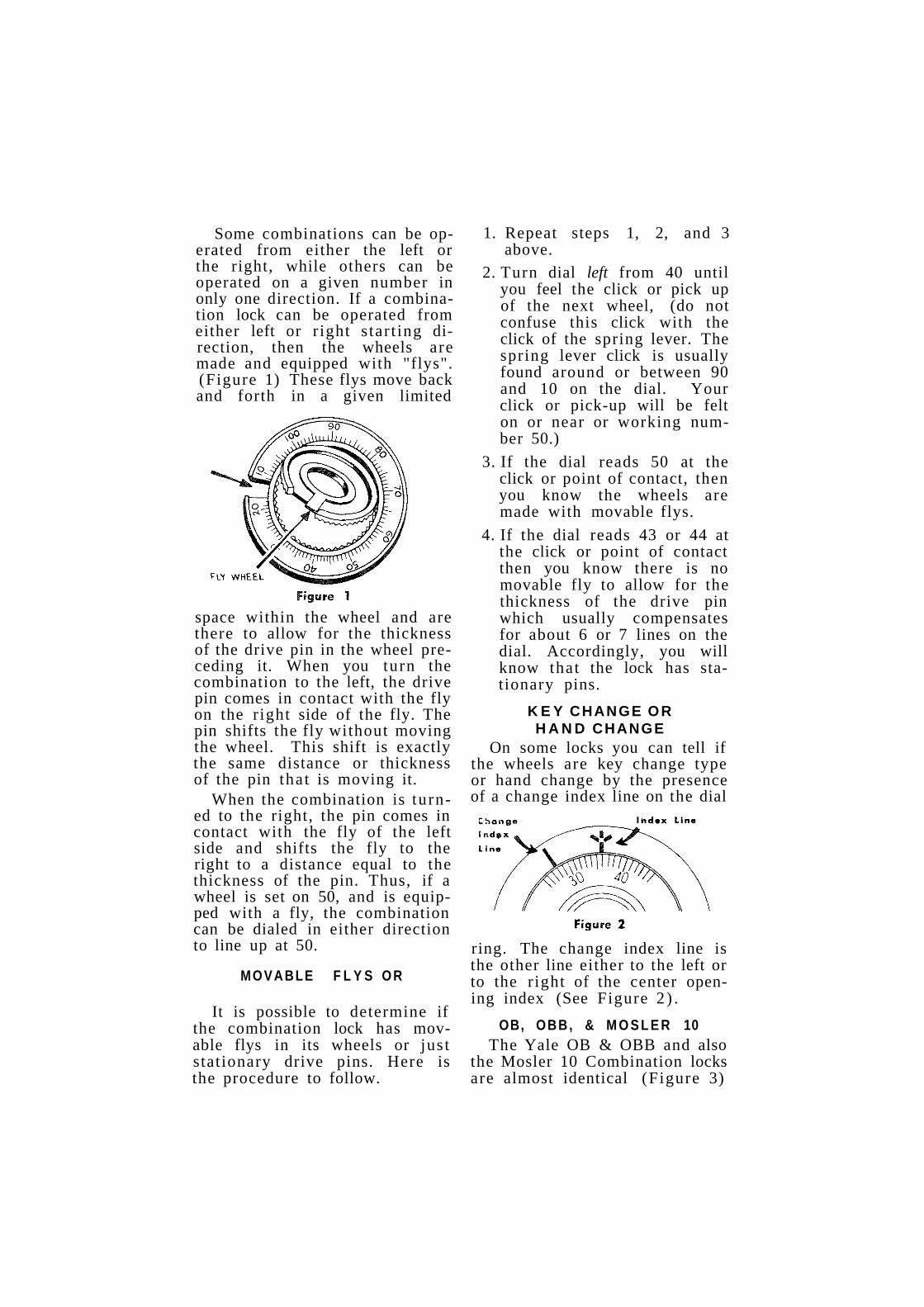
Some combinations can be operated from either the left or the right, while others can be operated on a given number in only one direction. If a combination lock can be operated from either left or r ight s tar t ing direction, then the wheels are made and equipped with "flys". (Figure 1) These flys move back and forth in a given limited
space within the wheel and are there to allow for the thickness of the drive pin in the wheel preceding it. When you turn the combination to the left, the drive pin comes in contact with the fly on the r ight side of the fly. The pin shifts the fly without moving the wheel. This shift is exactly the same distance or thickness of the pin that is moving it.
When the combination is turned to the right, the pin comes in contact with the fly of the left side and shifts the fly to the right to a distance equal to the thickness of the pin. Thus, if a wheel is set on 50, and is equipped with a fly, the combination can be dialed in either direction to line up at 50.
MOVABLE F L Y S O R
It is possible to determine if the combination lock has movable flys in its wheels or just stationary drive pins. Here is the procedure to follow.
1. Repeat steps 1, 2, and 3 above.
2. Turn dial left from 40 until you feel the click or pick up of the next wheel, (do not confuse this click with the click of the spring lever. The spring lever click is usually found around or between 90 and 10 on the dial. Your click or pick-up will be felt on or near or working number 50.)
3. If the dial reads 50 at the click or point of contact, then you know the wheels are made with movable flys.
4. If the dial reads 43 or 44 at the click or point of contact then you know there is no movable fly to allow for the thickness of the drive pin which usually compensates for about 6 or 7 lines on the dial. Accordingly, you will know that the lock has stationary pins.
K E Y CHANGE OR H A N D CHANGE
On some locks you can tell if the wheels are key change type or hand change by the presence of a change index line on the dial
ring. The change index line is the other line either to the left or to the r ight of the center opening index (See Figure 2 ) .
OB, OBB, & M O S L E R 10 The Yale OB & OBB and also
the Mosler 10 Combination locks are almost identical (Figure 3)

The locking and un-locking principal employed is the same. The lock consists of a lock case, the usual drive cam and wheel pack, and also a gravity controlled, weighted locking lever. The principal is simple and effective. When all the wheels are lined up
in opening sequence the gravity lever drops, allowing the bolt bar to pass by and open. When the combination is locked, the lever is up and thus obstructs the bolt bar from passing by. (Figure 4 ) .
The old Syracuse safe (no longer manufactured but still widely in use today) is equipped with Yale OB combination locks. A typical Standard Wall or in today's terms "Medium Wall" Syracuse safe is pictured below (Figure 5 ) . A lock-out on a Syracuse safe usually occurs because the bar bolt is jammed tight up aginst the Gravity Drop Lever, and even though the combination is working and even though the combination is working and all the wheels are in proper alignment, the safe will refuse to open. If the bar is in such t ight contact with the Gravity lever, the lever cannot drop (Figure 4 ) . In these cases, the bolts of the safe work very hard either because the worn door
hinges cause the bolts to rub on the receiving holes in the door jamb, or because they have become slightly bent by repeated slamming of the door while the bolts are sticking out. When these conditions exist, and the bar bolt is accidentally pressed hard against the gravity lever as the safe is locked, the owner will not get his safe open in the

morning! All you have to do, when you arrive on the job, is to tap the T handle, oscillate dial a little, and give the lever an opportunity to drop in. Once the safe is open, check for the reason why the bolts are working hard and make the proper adjustments.
If it becomes necessary to drill the safe because of lock breakdown or jammed bolts, drill a 1/4" or 3/8" hole at # 1 , (see special cha r t ) , and angle your drill up 10 degrees. Drill through outer face plate, insulation, then cast iron mounting plate and lock case.
Line up the wheels (usually 3 wheels and a dr iver) , sometimes 4 and a dr iver ) . Allow the lever to drop, (oscillating the
dial a litle helps) draw back bolts and open safe!
Another clean way to open this safe is to drill #2, remove wheel pack screws and follow further instructions on # 2 . A third way, (not the best, but far the quickest), is to drill at #3 and follow instructions. CAUTION! If the safe is equipped with a tear gas attachment be sure to follow instructions carefully. Otherwise you will set it off!
S C H W A B S A F E
The Modern Schwab safe also uses the Yale OB or OBB Lock with the Gravity drop lever. Figure 6 shows you the open and closed view of the modern Schwab safe, and Figure 7 clearly shows the mechanical functions of the locking mechanism. You will also notice that the Schwab safe is equipped with a hardened steel drill-resisting plate jus t behind the outer face
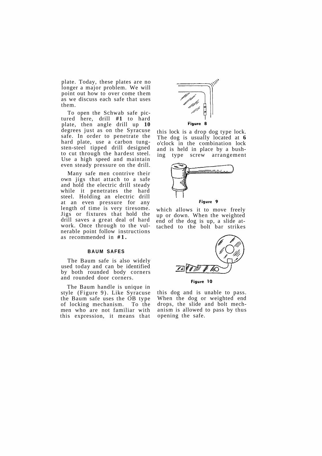
plate. Today, these plates are no longer a major problem. We will point out how to over come them as we discuss each safe that uses them.
To open the Schwab safe pictured here, drill #1 to hard plate, then angle drill up 10 degrees just as on the Syracuse safe. In order to penetrate the hard plate, use a carbon tungsten-steel tipped drill designed to cut through the hardest steel. Use a high speed and maintain even steady pressure on the drill.
Many safe men contrive their own jigs that at tach to a safe and hold the electric drill steady while it penetrates the hard steel. Holding an electric drill at an even pressure for any length of time is very tiresome. Jigs or fixtures that hold the drill saves a great deal of hard work. Once through to the vulnerable point follow instructions as recommended in # 1 .
B A U M S A F E S
The Baum safe is also widely used today and can be identified by both rounded body corners and rounded door corners.
The Baum handle is unique in style (Figure 9 ) . Like Syracuse the Baum safe uses the OB type of locking mechanism. To the men who are not familiar with this expression, it means tha t
this lock is a drop dog type lock. The dog is usually located at 6 o'clock in the combination lock and is held in place by a bushing type screw arrangement
which allows it to move freely up or down. When the weighted end of the dog is up, a slide attached to the bolt bar strikes
this dog and is unable to pass. When the dog or weighted end drops, the slide and bolt mechanism is allowed to pass by thus opening the safe.

types of safe locking mechanisms direct into wheel straight and force up lever gravity drop lever standard combination and lockouts on sentry, alpine, carey, wherle safes
There are four basic types of safe locking mechanisms in general use to-day. Figure 1 shows the simplest which consists only of a set of wheels and a bar bolt. When the wheels are in opening alignment, the bar bolt can pass to the opening position without obstruction.
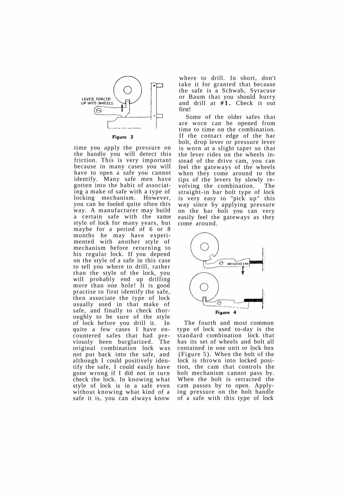
Figure 2 shows another version of the direct-into-wheel type of lock. When the gateways of the wheels are not in alignment, the bar bolt cannot be forced by the pressure lever. When the wheels are lined up in opening sequence, the bar bolt cams the pressure lever up into the gateways of the wheels, and slides under the raised lever as shown in Figure 3.
The gravity drop lever type of locking mechanism discussed in detail in the previous article is the third type of mechanism, and is very similar to the press-up or force-up lever lock with the exception that the lever in this part icular case is gravity controlled. When the gateways of the wheels are in alignment, the weighted end will drop down, while the t ip end enters into the wheels. When the wheels are not in alignment, the t ip end is in gentle contact with the drive cam, keeping the weighted end up and preventing the bar bolt from passing over it (Figure 4 ) .
Each of these three styles of mechanisms can be detected from the outside of a locked safe. By applying a slight pressure on the bolt handle you will cause the bar bolt and drop leverar pressure lever to press up into the wheels which in turn cause the wheels to turn hard. By turn ing the combination at the same
t ime you apply the pressure on the handle you will detect this friction. This is very important because in many cases you will have to open a safe you cannot identify. Many safe men have gotten into the habit of associating a make of safe with a type of locking mechanism. However, you can be fooled quite often this way. A manufacturer may build a certain safe with the same style of lock for many years, but maybe for a period of 6 or 8 months he may have experimented with another style of mechanism before re turning to his regular lock. If you depend on the style of a safe in this case to tell you where to drill, ra ther than the style of the lock, you will probably end up drilling more than one hole! It is good practise to first identify the safe, then associate the type of lock usually used in tha t make of safe, and finally to check thoroughly to be sure of the style of lock before you drill it. In quite a few cases I have encountered safes tha t had previously been burglarized. The original combination lock was not put back into the safe, and although I could positively identify the safe, I could easily have gone wrong if I did not in tu rn check the lock. In knowing what style of lock is in a safe even without knowing what kind of a safe it is, you can always know
where to drill. In short, don't take it for granted that because the safe is a Schwab, Syracuse or Baum tha t you should hurry and drill at # 1 . Check it out first!
Some of the older safes that are worn can be opened from time to time on the combination. If the contact edge of the bar bolt, drop lever or pressure lever is worn at a slight taper so that the lever rides on the wheels instead of the drive cam, you can feel the gateways of the wheels when they come around to the tips of the levers by slowly revolving the combination. The straight-in bar bolt type of lock is very easy to "pick up" this way since by applying pressure on the bar bolt you can very easily feel the gateways as they come around.
The fourth and most common type of lock used to-day is the s tandard combination lock that has its set of wheels and bolt all contained in one unit or lock box (Figure 5 ) . When the bolt of the lock is thrown into locked position, the cam that controls the bolt mechanism cannot pass by. When the bolt is retracted the cam passes by to open. Applying pressure on the bolt handle of a safe with this type of lock

will not make any appreciable difference in the feel of the combination. Thus when you approach a safe whose identity you cannot determine, and you do not get that " t ight" feel on the dial as you apply pressure on the handle, you can be pretty sure that it is a self contained combination lock. Usually with this type of lock you can feel the spring controlled lever between 90 and 10. As you oscillate the dial slowly in and around this area, you can feel the click of this spring controlled lever. If you don't feel the click of the lever then it is probably a lock with a gravity lever that drops in at the top.
The major cause of a lockout on safes that have direct-into-wheel t y p e mechanisms a s shown in Figure 1 is that the drive cam becomes loose and develops a slight two or three number play. This play causes the entire combination to run off. To detect this condition, locate your drive cam gateway by applying slight pressure on the bar bolt until the combination comes to a definite click or stop. Maintaining this pressure you then twist dial back and forth in the slot. Under normal conditions, when the lock is t ight and in good working order, the amount of play in the gateway slot is usually about 1 to 1 1/2 lines either side of center. If the dial
shakes more than the tolerable distance then you know the drive cam is shaking on the spindle. Check the wheels by feeling if they all pick up to make sure you do not have a "disconnect." If they all pick up, then you have only to allow the amount of play or shake on each wheel that was determined in the first test.
If the combination is 50-20-36, with 36 being your drive cam number, and the amount of play in the drive cam is 4 lines on the dial, s ta r t ing to the left you set your dial on 54, running to the left for your second number you set your dial on 16 or 20. Bring your dial back to the opening number and shake it back and forth, oscillating the bolt handle at the same time.
The major cause of lockouts on safes that use pressure lever mechanisms is lack of proper lubrication. There is so much friction between the contact point of the lever heel and bar bolt, tha t the two just refuse to budge and just lock into one another. If the bushing is dry, the condition then is worse. There is no way you can get oil into the safe at this point of contact but the safe can be opened nevertheless. Set the combination very accurately. After your last number is set, hold the dial so that it will not shift or walk, while you tap the bolt handle rapidly in the direction of the opening. The rapid tapping will vibrate the lever so that it will eventually work up into opening position.
Always first check the feel of the lock, to determine if all the wheels are picking up as you revolve the dial. If they are not that you have a broken fly, or

a snapped off drive pin. Drilling, of course, is indicated in this case.
If all the wheels are picking up, then chances are pretty good that the spring lever is jammed. Oscillation, tapping, vibrating on the dial, bolt handle and in the general area of the combination is about all you can do to shake the par t loose.
The type of combination mechanism shown in Figure 1, namely the s t raight in direct lock is not too common today. It is used exclusively however by the Sen try Safe (Figure 6) which is a very popular small home safe. The lock consists of two wheels and a drive wheel.
The drive pin of the drive wheel is the head end of a small brass bolt which is held in place by a small lock washer, a nut and lock nut. The drive wheel fits on to the dial shaft spindle and is held in place by a very t ight fitting nut. If it becomes necessary to drill this safe open, follow this procedure:
Locate the gateway of the drive cam by applying slight pressure on the bolt handle.
When the dial comes to a definite stop you have your opening number or drive cam gateway. Keep handle pressed into gateway slot while you drill straight in at # 4 . Ugly repair marks and paint matching are thus avoided. Line up the wheels with sharp pointed steel probe.
Figure 7
The Alpine safe (Figure 7) which is easily identified by one piece band steel wraparound construction also used this system of locking. To open drill at #5 while angling the drill 5 degrees right. Line up wheels, draw bolts, and open safe.
The Carey Safe (Fig. 8) uses s traight in lock also, with the ex-

ception that the combination is geared. There is a greater distance between the handle and dial of a Carey safe than usual. To open drill #6 straight in. Line up wheels, draw bolts.
Carey sujes use two other locks that I know of. One is geared upwards but otherwise straight-in-direct, and the other uses a Yale lock, right to stop. These safes look the same on the outside. The Carey model using the Yale lock has the Carey name marked on the dial knob.
This safe is equipped with a stubborn hard plate but can be entered. To open, drill at # 8 . The other straight-in direct lock Carey used on some of their safe is geared upward. To open drill at # 7 , line up wheels, or drill off bar bolt.
The Wherle safe also uses the s t raight in direct locking mechanism. Wherle safes are all set on the same combination ( r e : coded cha r t ) . To open, drill # 5 , angle drill in 10 degrees, line up your wheels, draw back bolts.

Detection and try out methods explanation of techniques lockouts on invincible, rand and meilink file cabinets
The first par t of this article is devoted to opening safes by "detection". By this I do not mean manipulation, but rather how to decode the combination from the mixed up information that people give the safe man. People are creatures of habit. These habits are strangely common to all and, those tha t people have with regards to safes and combinations follow almost a universal pattern. Some of these universal trai ts that people have formed can be put to very good use by the safe man in helping him in his job of opening.
When I was very young and tagged along with my dad on some of his jobs, I recall one incident very clearly. He was called to open a safe for a family, the head of which had jus t died. It was a small house safe that was placed right next to a closet. The closet door was slightly ajar. I saw my dad "accidentally" open the closet door (I later found out this was no accident) . He peeked quickly up and down and all around the door jamb. With professional agility he sat himself down in front of the safe and requested that I hand him the electronic wire in the tool kit. This was a new and fancy expression and in my innocence I handed him what to me was an old piece of bell wire. He looped one end of the wire around his ear and held the other end of the wire up against the safe, while operating the dial. Within five minutes he had opened the safe. I thought to myself, "Gosh, dad
is the greatest! How does he do i t?"
On the way back to the shop I felt very proud of him and told him so. Then I went on to ask why he drilled so many safes open if he could open them so easy with an "electronic wire." Dad then explained to me that the wire was only a hoax, a distraction. The combination of the safe was clearly written on the door jamb. He merely read it off as he dialed the safe, but he didn't want any of the others to know what he was doing. He used the wire to at t ract their attention, and at the same time made the whole procedure look very mystifying and professional.
Yes, people do things like that all the time with their safe combinations. Some even write it on the side of the safe! I have found that this habit of writing down combinations is universal. Generally speaking, it may be written on something within arm's
distance of the safe. A very popular place is on the edge of a window or door casing. Sometimes it is even taped underneath the bottom of the safe. Accordingly, it is always good practise to inspect the area around the safe. Quite often you will come up with the combination.
Another practise that many people adhere to is that of setting the safe combination on their birth dates such as 6-27-18 (June 27th 1918). If it isn't their birthday, it may be their wedding aniversaries or the year their first child was born. Any date that comes to a man's mind without effort may be used. Always ask about the deceased. When was he born?— day, month, year? Ask about his marriage date, house number, wife's birthday, child's birthday, etc. From these numbers you can very often put together a combination and open the safe.
Once a widow handed me a piece of paper on which the combination of the safe was written. The deceased didn't intentionally code it, he just wrote it down the way he thought it should be. Little wonder no one could open it. Here is what was written on the scrap of paper:
L 25 25 25 L 60 continue to 45 Back to 45 Back to 30 30 then open
It takes a little science plus imagination, but you should be able to de-code it fairly easily. The above combination turned out to be:
R 4 x to 25 L 3 x to 60 R 2 x to 45 L to stop on 30
You can usually depend on the accuracy of the numbers. Pay little or no attention to the direction of the turns. Using the numbers as written, follow your normal sequence of 432. Star t in the direction you feel is right. Sargent and Greenleaf, usually turns RIGHT to stop. Yale usually turns LEFT to stop. Die-boid, RIGHT to stop, Mosler LEFT to stop.
Most safe manufacturers use a standard factory set combination on all their safes when they ship them to dealers. Although many of these combinations get changed when they are sold, many never do get changed. There is a 50-50 chance that the safe is still set on a factory number when you are called in. For these, kindly refer to your code sheets. The combinations are not exact, they have been coded. To decode add 10 to the first two numbers and leave the third as is.
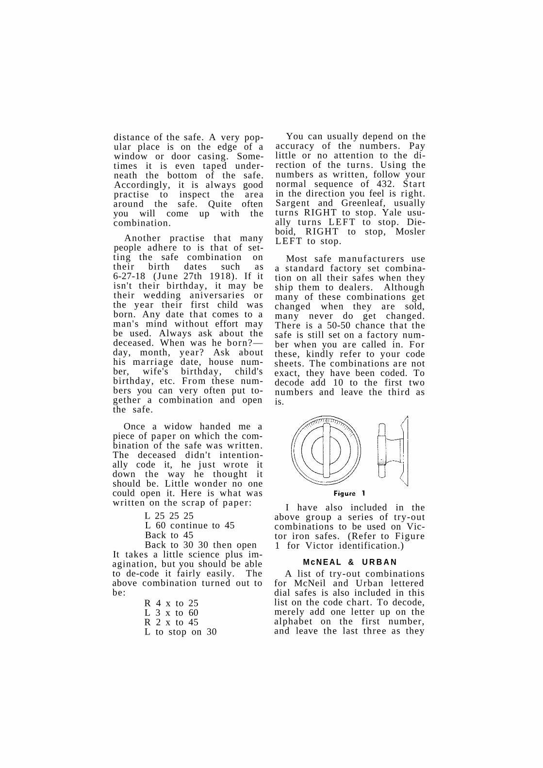
I have also included in the above group a series of try-out combinations to be used on Victor iron safes. (Refer to Figure 1 for Victor identification.)
M c N E A L & U R B A N A list of try-out combinations
for McNeil and Urban lettered dial safes is also included in this list on the code chart. To decode, merely add one letter up on the alphabet on the first number, and leave the last three as they

appear. Oscillate at К to shake the drop lever loose.
The Invincible Metal Furniture Co. of Manitowoc Wisconsin builds a file cabinet with a concealed safe unit in the top drawer section. The door of the safe is 1/2" thick and is locked by 2 bolts (up and down) and the bolt of the combination lock itself. A picture of this safe and cabinet is shown in Fig. 2. The factory set combination is the same as used by Remington-Rand with one exception: s tar t to the left. Refer to No. 11 on the code chart.
If by chance the combination on the Invincible has been changed and it becomes necessary to drill, it is possible to open this chest without disfiguring the door itself. The top bolt is located 1" from the top left corner of the door. The bottom bolt is located 2" in from the lower left corner of the door. If the door is one tha t doesn't fit too snug, it is possible to see these bolts by peeking through the crack of the door. To open this
safe without drilling use the procedure outlined in No. 11 of the code chart.
An alternate procedure that can be used to open these safes is to drill No. 12 disconnect lock and open door. This method is good if safe is not too full to obstruct your vision.
Quite often, Invincible chests will not "lock in." Because of constant slamming of the door with the bolt mechanism in a locked position, the top and bottom bolts or, as is more frequently the case, the lock bolt bends. The bolt cannot then line un into the bolt receiving hole. The procedure for correcting this ailment is simple. Just bend the bolts back again into their original position and lubricate the bolts. Warn the user against repeating such careless practises.
When an Invincible safe refuses to open, you will usually find that the combination lock bolt is very tight, or that it has been forced forward into locking position, thus creating extreme back pressure into the works of the lock itself. This prevents the parts from functioning freely. To open, run your combination in the regular manner even though it doesn't run too smoothly. At opening position oscillate and rap with a soft face hammer. The safe will then open.
While we are on the subject of filing cabinets with safes or combination locks, let us discuss a real troublesome insulated file to open. The Remington-Rand (with or without the manipulation-proof combination lock) can be really s tubborn! Only

the combination bolt checks the drawer ( but this bolt is protected on all sides by a hard steel jacket. You cannot drill through the drawer to reach the bolt, nor can you drill through the top of the safe where the bolt enters, because there, too, you will find a hard jacket. There is a way, however, of getting by this hard plate successfully without too much damage to the drawer head. In drilling, you are permitted no tolerance. You must be exact. Follow this procedure:
A — H a r d plate under outside skirt; В — L o c k b o l t ; С—Combination lock; D — Hard jacket around lock case.
Drill as instructed at No. 13. Refer to Fig. No. 3 for cross section of drawer head showing hard plates. After the holes are drilled as per instructions, use a fine hacksaw blade to complete the job. You will notice on examining the sketch in Fig. 3 that the combination lock is completely surrounded by a hard jacket. The lock is set into this jacket and bolted to it. It is practically impossible to drill through the lock at any point.
Although the manufacturer did a complete and thorough job of protecting this lock against drilling, they did leave this one avenue open to us. (Note : The Victor File cabinet can be opened in the same manner.)
M E I L I N K I N S U L A T E D
Meilink file cabinets can be locked with a key lock, combination lock or both. The locking
mechanism consists of a plunger on the right side of the file on the inside. When the drawer is closed, the end of the shaft of the plunger key lock just "kisses" the locking plunger. When you depress the key plunger lock, you also press in the

plunger bolt which operates on a linkage mechanism and drops the locking bar down behind the heavy spring in the linkage obstructions on the drawers. A mechanism allows the bar bolt to be drawn back to opening position when the key plunger lock is released. These files can be opened surreptitiously (without visible damage) if they have only the key plunger lock. Kind
ly refer to No. 14 on the master chart. This trick can be used also on almost all insulated or non-insulated file cabinets tha t have key plunger locks. However, since some locks will not open in this manner, do not be concerned if the trick does not work.. It is, after all, only a trick and should be used as such.
The Meilink insulated file cabinet comes equipped also with a combination lock. The lock can be arranged to lock just one drawer, or to control the locking of all drawers. Unlike the Remington-Rand insulated file, or the Victor Insulated file (which is actually a Remington-Rand) the combination lock is horizontally installed, with bolt facing to the right as you look at the file. (Figure 7) The combination lock on the Remington-Rand is inverted, facing upward.
The lock on the Meilink file is protected with a hard steel
A—Combination lock; В Combination lock bolt checks plunger; С To open, plunger must come out.
jacket and cannot be drilled easily from the front of the file. The locking action works in this manner : a plunger protruding from the face of the drawer is depressed to lock. The plunger is fastened to a linkage mechanism and bar that has a vertical up and down action. Pressing in the plunger moves the bar bolt downward and ultimately checks the drawers. The combination lock bolt, thrown into a locked position when the plunger is in, checks the plunger and prevents it from springing back out. When the combination lock bolt is withdrawn, the plunger snaps or springs back out and the bar bolt releases its check on the drawers of the file. (Figure 8) .
A — F r o n t edge of combination lock bolt; В — P l u n g e r controls locking action of drawers. Plunger in—locked; Plunger out—unlocked.

Where there is no combination lock, the plunger acts in the same way as in the universally used plunger key lock used on most ordinary files. These can usually be picked open. Since this information is so widely known and does not actually
pertain to safe lock mechanisms, we will not discuss this here.
To open the Meilink insulated safe file with the combination lock follow instructions outlined in No. 14A of the Master Code Chart.
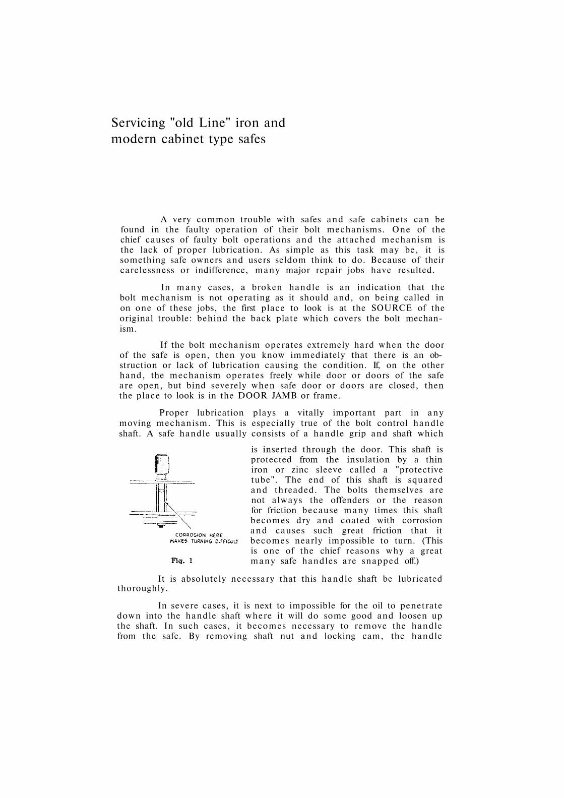
Servicing "old Line" iron and modern cabinet type safes
A very common trouble with safes and safe cabinets can be found in the faulty operation of their bolt mechanisms. One of the chief causes of faulty bolt operations and the attached mechanism is the lack of proper lubrication. As simple as this task may be, it is something safe owners and users seldom think to do. Because of their carelessness or indifference, many major repair jobs have resulted.
In many cases, a broken handle is an indication that the bolt mechanism is not operating as it should and, on being called in on one of these jobs, the first place to look is at the SOURCE of the original trouble: behind the back plate which covers the bolt mechanism.
If the bolt mechanism operates extremely hard when the door of the safe is open, then you know immediately that there is an obstruction or lack of lubrication causing the condition. If, on the other hand, the mechanism operates freely while door or doors of the safe are open, but bind severely when safe door or doors are closed, then the place to look is in the DOOR JAMB or frame.
Proper lubrication plays a vitally important part in any moving mechanism. This is especially true of the bolt control handle shaft. A safe handle usually consists of a handle grip and shaft which
is inserted through the door. This shaft is protected from the insulation by a thin iron or zinc sleeve called a "protective tube". The end of this shaft is squared and threaded. The bolts themselves are not always the offenders or the reason for friction because many times this shaft becomes dry and coated with corrosion and causes such great friction that it becomes nearly impossible to turn. (This is one of the chief reasons why a great many safe handles are snapped off.)
It is absolutely necessary that this handle shaft bе lubricated thoroughly.
In severe cases, it is next to impossible for the oil to penetrate down into the handle shaft where it will do some good and loosen up the shaft. In such cases, it becomes necessary to remove the handle from the safe. By removing shaft nut and locking cam, the handle

should pull out, but in many cases because of the severe corroded condition within the tube, the handle will not yield. A few blows with a good size hammer usually will loosen the handle. It is not advisable, however, to strike the threaded end of the handle shaft, because the threads may become damaged. The correct procedure is to place the nut back on the shaft after all other parts of the mechanism in between have been removed. The nut will protect the thread from damage as you strike the shaft.
Once the handle is loose, remove the shaft nut and drive shaft out the remainder of the way. Clean out the corrosion and scrape the tube clean. Always use a good grade of medium grease and lubricate the handle shaft and moving parts of the bolt mechanism. Do not use oil, grease has more body, resists temperature changes bettter without running off, and lasts much longer than oil.
As mentioned previously, many bolt mechanisms may work freely while safe door is in the open position, but bolts bind up when door is closed. Sometimes it gets to the point where it is impossible to lock the safe completely. Any number of reasons could exist for the bolts to lose their alignment
with the corresponding bolt, holes in the door jamb.
In cases where incorrect alignment is not too severe, grinding out the bolt holes will again permit the bolts to pass freely and smoothly. In more severe cases, however, it will be necessary to search a little deeper far the main cause or source of lost alignment. For instance, worn hinges will cause the entire door to drop or sag and fit poorly into the frame, thus throwing out bolt alignment. In other cases, repeated slamming of the safe door with the bolts out in the locked position will bend and damage the bolts and inner bolt bars so that they no longer slide into the bolt openings.
If the bolts are bent the best procedure is to remove the bolts entirely and straighten them.
However removal is not always as easy as it looks! On a number of different makes of safes it cannot be done without taking the entire door apart. Therefore, unless you have had safe-building experience, it would be unwise to attempt it.
Assuming that the bolts are not removable, but need straightening it may be possible to do this from the outside. With the bolts in the locked or extended position, place

a wedge or a chisel between the bolt and any protruding edge of door jamb as shown in Fig. 4. The force of the wedge being driven in will bend the bolts back again to their original position.
It may not be necessary to do this to every bolt, and it is certainly a wise act to examine all bolts closely first to determine which one is causing the trouble.
Once again, grind out the holes slightly to insure easy fit. Then lubricate with grease, and the job is just like new!
The case of the sagging door will present a greater problem. Because of the extreme weight of safe doors, and the absence of lubricants, safe hinges usually wear excessively. Hinge pins will wear badly too, especially the top hinge of a two-hinge safe door.
If the door is not too heavy, it is better to remove the door by lifting it off its hinges so that you can get at the hinge pins and make the necessary repairs. However if hinge pins are permanently affixed and cannot be removed, the best thing to do is to bend them out to offset the wear. The combination of worn hinges and hinge pins not only causes a door to drop but also causes it to tip or sag. By bending the hinge in the necessary direction the sag or tipping is eliminated.
The next step is to raise the door up to its original position. If
the door is too heavy to remove altogether, it is still possible to repair its hinges. For this operation you will need a small screw type jack. With the door in an open position place jack under the door approximately 5" in on the hinge side. Jack door up approximately 1".
Since most hinge pins are 1 1/2" to 2" long it is not probable that the door will become dislodged, but EXTREME CAUTION should be used in the event hinge pins are shorter than usual! Since the top hinge pin wears toward the outside (the door usually sags away from the hinge and down),
and the bottom hinge pin wears towards the inside (door sags into bottom hinge), it is necessary to compensate for the worn section's of the pins. With the door raised up about an inch it is possible to get at the hinge pins with a still-son wrench. Place the wrench between the two halves of the hinge and proceed to twist the pin around to a position just REVERSE of the wear.
The above procedure usually works out very successfully. In the exceptional case, however, it

may be necessary to employ a professional rigger to remove the door completely from the safe.
Now, since the halves of the hinges themselves are also badly worn it is necessary to build them up to their original position again before the door will fit properly. The best way to build up on a hinge is to add a steel washer to compensate for the wear. Of course, with the safe door removed it is simple to drop a washer over the top of the hinge pin. But if you have the door in a jacked-up position, you have another problem . . . how to get it on! WARNING: DO NOT CUT A WIDE SLOT IN THE WASHER TO ALLOW IT TO PASS ON TO THE HINGE PIN. In no time at all the washer will work loose and you'll have the same job to do over again (without charge this time)!
It is possible to place a full washer around a hinge pin by splitting it. The split should be no wider than the thickness of a hacksaw blade. Bend the two ends of the split washer in opposite directions so that it takes on a figure "S" appearance.
Place the washer on the hinge pin, give it a slight twist so that it is in position for compressing. Then lubricate the pin with light grease. When you lower the door back into position the washer will flatten out and seat itself around the pin just as though it were placed over the top of the pin! Such a washer will never work loose.
If the door still binds at the bottom, perhaps the washer used was not thick enough. Or, if the door now binds at the top, the washer- used was too thick. Usually, filing with a sharp rasp over the binding surfaces of the door will overcome the bind so that the door closes nicely and the bolts throw smoothly into locking position.
Modern cabinet type safes are the worst offenders for poor fitting doors and extremely hard-working bolt mechanisms. It seems as though a chemical reaction takes place through the years causing these safe cabinets to swell. If this swelling becomes too severe there is nothing that can be done to ease the condition. However, in less severe circumstances it is possible to get the doors back into a fairly smooth operating condition.
Always check hinge wear and possible bent bolts first. Cabinet type safes wear badly and quickly

at the hinges, but usually the doors of cabinet type safes do not tip because hinges are wide and numerous (usually four per door on double door safes). If the door of a safe cabinet strikes on the bottom it will usually be found that the hinge sections have worn. You can take up this wear by inserting extra thin washers under the worn sections. Here is the procedure to follow: Shim up the door on the lower frame. Remove the hinge pins one at a time. Now with the hinge pin out you can proceed to slide washers into the spaces between the leaves of the hinge. The washers should be thick enough so that it is necessary to tap them in under slight pressure. Re-insert the hinge pin and repeat this procedure with each hinge. Repeat the entire procedure, if necessary, until you have a perfect fit.
Where doors and door jambs of cabinet type safes have swelled, and doors bind badly, there are two things you can do. First, find out where the door strikes. You will probably discover on close examination that it strikes at several different points. You can de-
press these swollen points by pounding them with a heavy hammer through a block of hard wood. The wood disperses the weight of the blow and prevents ugly hammer marks on the safe. If the swollen surfaces a re not too severe this method will suffice. In extreme cases, it might become necessary to grind out high spots. Use a portable disc type grinder. The disc of the grinder fits under the tongue or groove of the door jamb and grinds down a larger surface more evenly than the conventional hand grinder.

Servicing burglarized safes
neutralizing explosives
METHODS OF WORKING SPINDLE
COMPENSATING FOR KNOCKED-OFF dials and handle
Burglars usually employ one of three methods to open safes. First , there is the crude at tempt by knocking off the dial and "spindling" the lock. Another is "peeling" whereby the front steel plate is peeled or stripped for the door jamb, the insulation gouged out, and the locking bolts yanked out. A third crude method, somewhat similar to peeling, is t ipping the safe and pulling out the bottom. Fortunately these approaches are not as successful as the newspapers would have the people believe.
Burglarized safes are sometimes very difficult to open. Although the burglar creates business for the safeman, he is nevertheless a bungler. He uses little or no science and almost always damages the safe unnecessarily. He seems to love to knock off the handle that controls the bolt mechanism,and he quite often breaks off the door hinges. And in spite of all the locksmiths technical knowledge of safe opening, such jobs can be rough going!
When called in on a burglary, never touch the safe until you have given it a thorough examination. A burglar can leave an unopened safe in a very dangerous condition! The hinges could have been broken off, or perhaps a charge of unexploded nitroglycerine is still present ready to be triggered. In one or two cases I have discovered severed hinge pins r ight at the point where the two halves of the hinges come together! Unless you look for it, you can barely notice when the hinge has been sawed. Always check the hinge pins of a burglarized safe—even if the hinge tips are still in place. Make sure that when the door is opened it will not fall on you or anyone else.
An unexploded charge of nitro or other liquid explosive can be detected usually by the presence of a soapy or putty-like substance on the safe. The putty acts as a sealant to keep the nitro in place. Also, you can detect nitro by a peculiar acid smell. If you are the least bit suspicious tha t the safe has been "souped" or prepared for blowing, use every precaution! Do not hit or vibrate the safe in any way. Star t working on it as quickly as possible. The longer nitro-glycerine stands, the more potent it becomes. Plain wood or denatured alchohol can be used as the neutralizer. To improve this mixture you can add some sodium sulphite crystals and dissolve thoroughly. Apply this mixture generously in all openings,

around the cracks of the door, and in any holes that may have been drilled by the burglar. Let the neutralizer work about half an hour. Then repeat the flushing out again.
Once you s tar t to work on a safe, do not allow the drill tap to heat up. Back off, let it cool, and then proceed again.
When the dial and handle is knocked off a burglarized safe, it is sometimes difficult to determine what style of lock is in the safe. Consequently the problem looms as to where to drill. Generally speaking there are three areas in which you can drill and be reasonably sure you will str ike a vulnerable par t of the lock. For these positions refer to # 9 . Of course, usually when a safe is burglarized and the exterior connections have been severed, it makes little difference what your aproach is. Since the safe is already damaged, it matters little if you extend the damage such as by drilling to punch off or disconnect a part.
In many cases you will encounter hard steel drill resistive plates within a safe. Sometimes these drill-resistive plates are jus t behind the face skin, sometimes they are just halfway in between the outside plate and
the lock. If the hard plate is just under the front plate it can be ground out very quickly. We use a small hand grinder that holds a mounted abrasive. The grinding portion of the point is mounted on a steel shaft tha t fits into the grinder chuck. We drill a good size hole through the outside steel plate as far in as we can go. Then we use the grinder holding it at a 45 degree angle as far in as we can go. Then we use the grinder, holding it at a 45° angle to the safe. (Holding the grinder at 90 degrees or s t raight on is of little or no use because it is the sides of the wheel that do the work!)
You can grind a hole in a hard plate in half the time it takes to drill a hole! That 's why I recommend the grinder when the hard plate in found just under the "skin", outer steel plate (face plate) , If, however, the hard plate is located further in, or just under the lock box to protecting it from drilling, then a carbide tipped drill will usually get you through. Some safe men have told me tha t they use ordinary, inexpensive cement drills with great success.
You can also cut out a hole with a torch. But the hole leading into the hard plate must be at least 1 1/2" to 2" in diameter to permit the torch to burn efficiently. A smaller opening will only cause the burning tip to get red hot and melt. Also, there must be enough space for the slag (burned metal) to flow.
There is available an element that can be set into the clamp of an electric welding outfit which will melt metal without flame. The commercial name is "Cut-rode." It resembles a stick of

carbon. This cutrode element will flash jus t like the ordinary welding element, but it melts the metal on contact. To use this, you must be sure that your outside hole is large enough to permit the cutrode element to pass through without touching wherever it makes contact with metal it burns.
You may find an attempted burglary where the dial had been knocked off and the spindle was not touched. If the spindle is still free and moveable, it is possible to open the safe without drilling. Drill a small 8" hole directly through the center of the spindle hub. Drill the same hole in the corresponding place in the dial hub. Use a slightly larger pin and tap it into the dial hole. Hold the dial over the spindle hub on the safe in the same position of the break and tap the dial on to the spindle. Now, the dial and spindle are reconnected and you can work the lock, using the combination furnished you by the owner. Since it is probable that you will not at tach the two parts perfectly, your alignment will run off slightly. Merely run the combination over or under two, three, four or even five numbers then oscillate at the opening point.
If you are not prepared to fit a drive pin into the spindle and dial you might t ry this method, which I have used hundreds of times with great success. F i rs t of all let me explain how a
spindle is attached to the dial : If you will look at an ordinary fire-proof type spindle manufactured by Yale or Sargent and Greenleaf, you will notice that the spindle and the dial are two distinct parts . One is fitted into the other. The spindle is usually threaded into the dial hub. Through this hub or shoulder bearing you will notice a pin. This pin is driven right through the two par ts after they have been screwed together. This is the weakest point on the spindle. When a dial is knocked off a safe it will inevitably break off right at the pin. As you look at the end of the spindle where it sticks out of the safe you will
see a half round slot. If the spindle is not damaged further, you can insert a screw driver blade into the slot and revolve the spindle shaft and work the combination.
Here is how you line UP the combination: Clear the combination all around to the right or as the case may be, all around to the left, depending on how the owner gives you the numbers of the combination. Let us assume that the numbers are 20-40-60 running to the right. Clear your combination to the right with the screw driver. Holding the severed dial in your hand turn the dial to 20. Tip the dail back and look at the position of the half round slot. Figure 3. The slot of the spindle now must be positioned to line up with the slot in the dial.

Let us assume that the slot in the dial slants down from 10:00 o'clock to 4:00 o'clock when the dial is set on 20. The slot in the spindle therefore must also be positioned the same way if the combination is to work. You then position the spindle with the slot slanting down from 10
to 4 making sure you have the right end of the slot up. (You can usually determine this by the characteristics of the break irregularities on either side of the slot.) Mark this position with a pencil on the safe, jus t outside the spindle. Continue this procedure for the other two numbers and mark. In effect you are using the slot or substituting the slot for the combination number and you are bound to run off because all you have is an approximate position to place this slot.
Using the screw driver, you turn the spindle just as if it were the dial. You clear it all around to the r ight and stop at the mark you positioned as your first number. Then you run the combination around to the left three times to your second indicated position. Finally, turn to the r ight two times to your third indicated position. Draw the spindle back to where you feel the click of the opening point
and oscillate as rapidly as you can.
In using this method, you will have to vary your positions slightly each time. By slightly, I mean only a hairline, because a hairline variance at the spindle may represent six numbers in the lock! As you know, the outer edge of a dial turns a much greater distance than its spindle because its diameter is perhaps ten times as large. Thus, much less movement is required than with the dial.
It may take a dozen or more tries before you succeed in opening the safe, but once you get the knack, it will prove to be a neat time and work saver. All you have to do after the safe is open, is to repair any minor damage within the lock, furnish and install a new dial, dial ring and spindle and leave your customer happy he called you because his safe's as good as new.
If the bolt control handle is also knocked off, you have two openings to perform. One, release the lock; two, release the bolt mechanism. If the safe is small it is possible to t ip the safe over on its side after the combination has been released, and vibrate the door with a heavy five pound hammer to encourage the bolts to drop back by gravity. If this is impractical it becomes necessary to drill for the bolt mechanism.
There is no hard and fast rule to follow on drilling for any bolt mechanism. If by a minor miracle a man would guess the exact location where the bolt enters the cup or receiving hole in the door jamb, he can drill around the side of the safe

and punch back the bolt. This however, would be a ra re instance. Very few safe men, if any, have dimensions of this nature. Usually if you drill a hole directly above the hole of the handle you will come in contact with the bar bolt that controls the bolt mechanism. Get a stiff punch or drift behind this bar bolt and force the bolts back to their opening position. If the
first hole doesn't reveal anything, then fan another hole up or down, left or right, until you find it.
In using the punch or drift as a lever to draw back the bolt, it may become necessary to help it along by pounding the door. This helps release pressure on the bolts. Vibration always plays an important role in safe opening!

Herring hall marvin safes spindle servicing
relocking mechanism vault doors
round door chests
One of the most popular safes in use today is the Herring-Hall-Marvin. You will find many of the old line, cast iron jamb "HHM" safes in wide use, and no doubt you will have many calls to service them. This model is shown in Figure 1. It can easily be identified by the gold stripe all around the front outer edge of the safe. The name Herring-Hall-Marvin is printed in gold lettering on the top front edge of the safe. The bolt operating handle is very large, measuring approximately 6 1/2", and is removable from the outside. It is held in place with a screw. Besides the drop handle, many H. H. M. safes also used the "T" handle. Like the long drop handles, the T handles fit over the shaft which protrude from the safe. These removable handles are attached by a screw that can be seen right in the handle.
For a positive identification, you have only to look at the combination dial. The hub of the combination is clearly marked Herring-Hall-Marvin, although the lock was actually manufactured by Yale. The Yale catalog number and style of the lock is " H E " . When the gateways of the wheels in this type lock are in alignment, the lever is pressed up into the wheels, allowing the bolt mechanism to pass by (Figure 2 ) .
Most of the Herring-Hall-Marvin safes you will encounter will have hard steel, drill resistive plates. With the exception of a few small models for home use, all HHM safes come through with hard plates. The hard plate is 1 / 4 " thick. It is movable up and down. The reason for this is tha t the hard plate fits in a slot or track in the
spindle. If the spindle has to be removed for any reason, the hard plate must be raised to permit the spindle to pass by. (Figure 3 ) . When the hard plate is in place, it serves two purposes: it protects the vulnerable par ts of the combination lock against drilling, and it collars the combination spindle
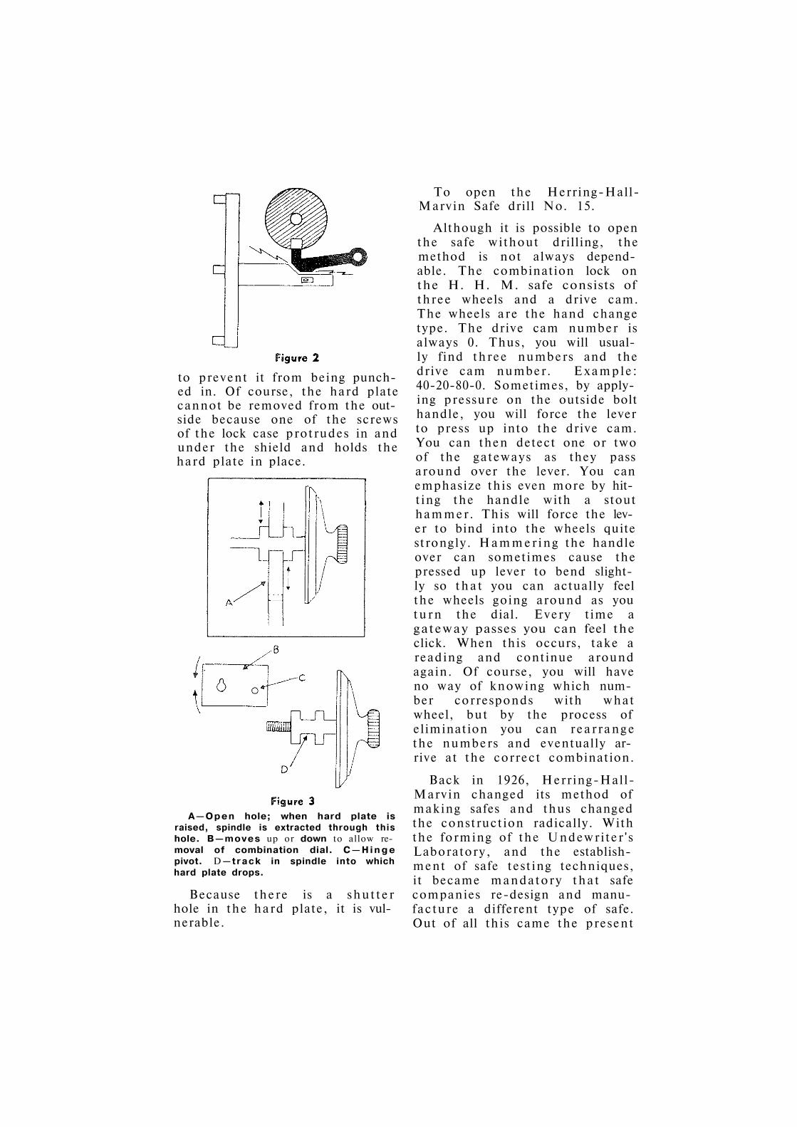
to prevent it from being punched in. Of course, the hard plate cannot be removed from the outside because one of the screws of the lock case protrudes in and under the shield and holds the hard plate in place.
A — O p e n hole; when hard plate is raised, spindle is extracted through this hole. В — m o v e s up or down to allow removal of combination dial. С — H i n g e pivot. D— t r a c k in spindle into which hard plate drops.
Because there is a shutter hole in the hard plate, it is vulnerable.
To open the Herring-Hall-Marvin Safe drill No. 15.
Although it is possible to open the safe without drilling, the method is not always dependable. The combination lock on the H. H. M. safe consists of three wheels and a drive cam. The wheels are the hand change type. The drive cam number is always 0. Thus, you will usually find three numbers and the drive cam number. Example: 40-20-80-0. Sometimes, by applying pressure on the outside bolt handle, you will force the lever to press up into the drive cam. You can then detect one or two of the gateways as they pass around over the lever. You can emphasize this even more by hitting the handle with a stout hammer. This will force the lever to bind into the wheels quite strongly. Hammering the handle over can sometimes cause the pressed up lever to bend slightly so that you can actually feel the wheels going around as you turn the dial. Every time a gateway passes you can feel the click. When this occurs, take a reading and continue around again. Of course, you will have no way of knowing which number corresponds with what wheel, but by the process of elimination you can rearrange the numbers and eventually arrive at the correct combination.
Back in 1926, Herring-Hall-Marvin changed its method of making safes and thus changed the construction radically. With the forming of the Undewriter 's Laboratory, and the establishment of safe testing techniques, it became mandatory that safe companies re-design and manufacture a different type of safe. Out of all this came the present

day pressed steel type safe. The gauge of the steel is much lighter than previously, and the door and body jambs are no longer made of cast iron. All the jambs are now pressed steel. The door and body jambs are tongued and grooved in contrast to the old step jamb.
Since there are many in the safe and lock business today who are not familiar with the advantages of the tongue and groove construction, the following information will be of value: The weakest point of a safe is where the door fits into the body of the safe. Here is a natural entrance for fire and heat. Through the use of tongue and groove, fire and heat do not have direct passage into the interior of the safe. The passage is obstructed and entrance is prolonged. Also, the tongue and groove tend to lock into one another more tightly as the safe gets hotter. This locking action holds the safe together by pre-
venting the walls from pulling away from the doors as the metal expands under heat.
The modern H. H. M. safe is pictured in Figure 4. You can see clearly the long drop handle and the stout acorn hinge tip are used. The lock on the 1926 model safe is brass and the hard plate has changed. The method of locking is the same, however. The pressure lever style as used on the older models is also used in this model.
The hard steel drill resistive plate used on the modern H. H. M. safe is located just under the outer face plate. It extends from well outside the handle, over to, and outside the combination dial.
This safe does not have a re-locking device. The hinge side of the door is equipped with a spring sealing device. As this flat spring (which extends the entire height of the door) , gets rusty and dry, it tends to cause the door to bind. It is well to clean this spring with emery paper, or steel wool and give it a thorough lubrication. Like the old Herring-Hall-Marvin safe, you can feel the drive cam as you turn the dial by applying pressure on the outside bolt handle. It is possible also to feel the wheels if the lock has had a great deal of use and is worn. To open this 1926 model Herring-Hall-Marvin safe drill at Number 16.
The H e r r i n g - H a l l - M a r v i n HAMILTON LINE (Figure 5) safe is a low cost, one hour small size safe designed for home owners and the small retailer. It comes in four sizes ranging in height from 22" to 40". It is constructed of light gauge pressed metal. The com-
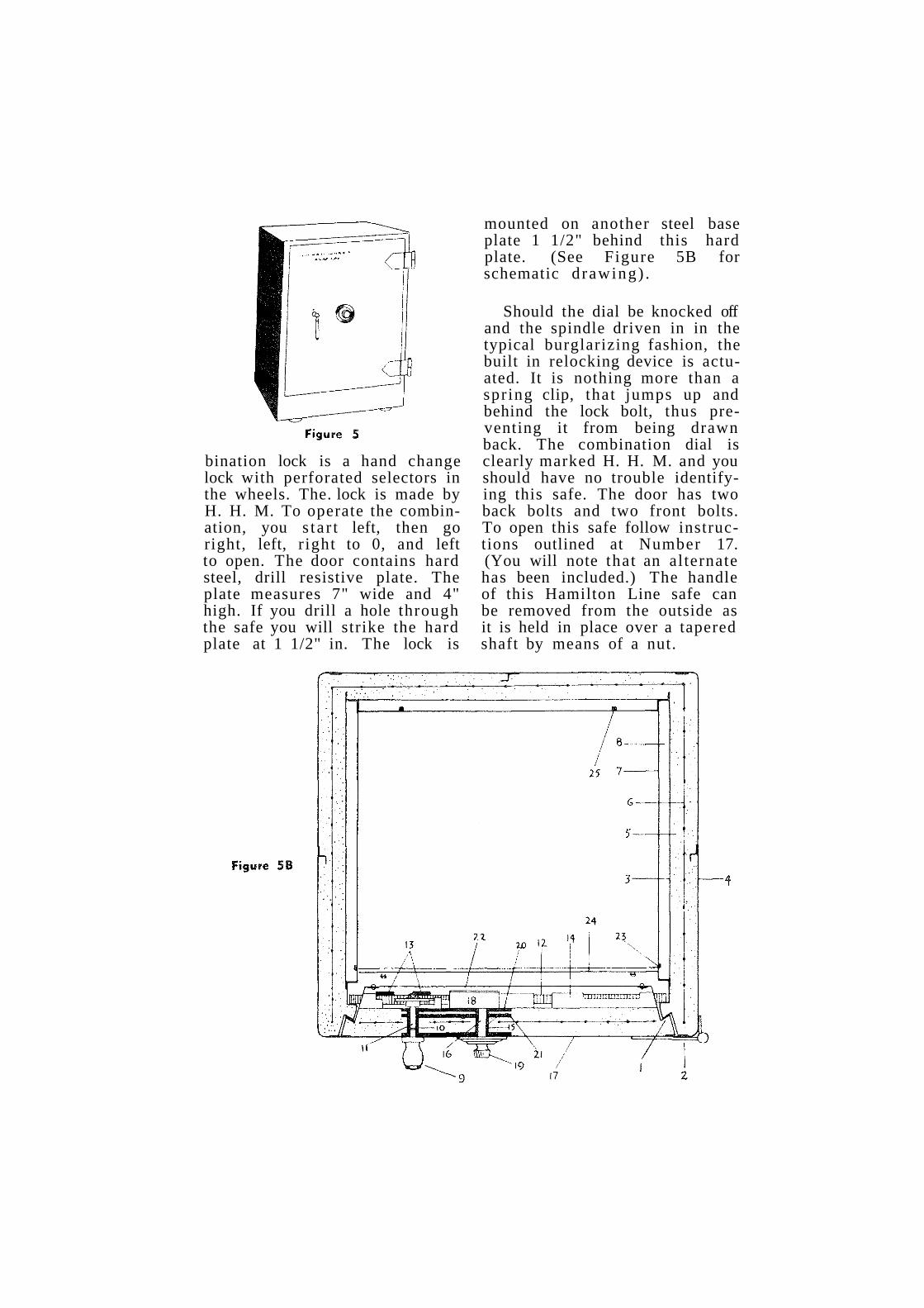
bination lock is a hand change lock with perforated selectors in the wheels. The. lock is made by H. H. M. To operate the combination, you s ta r t left, then go right, left, r ight to 0, and left to open. The door contains hard steel, drill resistive plate. The plate measures 7" wide and 4" high. If you drill a hole through the safe you will strike the hard plate at 1 1/2" in. The lock is
mounted on another steel base plate 1 1/2" behind this hard plate. (See Figure 5B for schematic d rawing) .
Should the dial be knocked off and the spindle driven in in the typical burglarizing fashion, the built in relocking device is actuated. It is nothing more than a spring clip, that jumps up and behind the lock bolt, thus preventing it from being drawn back. The combination dial is clearly marked H. H. M. and you should have no trouble identifying this safe. The door has two back bolts and two front bolts. To open this safe follow instructions outlined at Number 17. (You will note that an alternate has been included.) The handle of this Hamilton Line safe can be removed from the outside as it is held in place over a tapered shaft by means of a nut.

As the safe is used, the handle will tend to shift slightly from its normal vertical position if it is not absolutely t ight on the shaft. If you see this on a job sometime, don't be puzzled at the position of the handle. Merely loosen the nut, place the handle in its original position and tighten the nut securely.
If the handle is removed, you will see the tapered shaft prot ruding from the safe. The shaft is installed from the outside of the safe and butts up against the outer face plate. By grinding the shoulder off this tapered shaft, it is possible to push the shaft inwards. If one of these safes is burglarized, you might remember this as a good way to release the bolt mechanism.
The modern Herring-Hall-Marvin vault door is equipped with an inside escape device. To operate this device, you press in the escape device plunger and turn the handle to open. What actually takes place when you press in the escape device plunger is th i s : The combination lock bolt is made in two parts. The
end of the bolt is fastened to the main portion of the bolt by a hinge pin. Fitted in between the two portions, and over the pin, is a spring. The tip of the bolt can be pushed aside to allow the cam to bypass. (Figure 6 ) .
These HHM vault doors are equipped with hard steel drill resistive plates to protect the combination. To open, follow instructions at No. 18.
The Herring-Hall-Marvin Co. manufactures several lines of burglar-resistive round door money safes. One of these models is in wide use. It can be identified by a T handle that is
1— Tenon and groove 14—Locking bolt channel 2—Hinge 15—Combination lock arbor 3—Inner steel lining tube 4—Outer steel shell 16—Combination lock arbor -5—Monolithic insulation stainless steel 6—Reinforcing 17—Door plate 7—Perforated removable inner 18—Combination lock
lining 19—Combination lock dial 8—Air space 20—Lock plate 9—Throw bolt handle knob 21—Drill resistive protector
10—Throw bolt handle arbor plate tube 22—Cover plate
11—Throw bolt handle arbor - 23—Retractable shelf locking stainless steel pin
12—Locking Bolts 24—Front edge of shelf 13—Carrying Bars 25—Rigid rear shelf holding pin
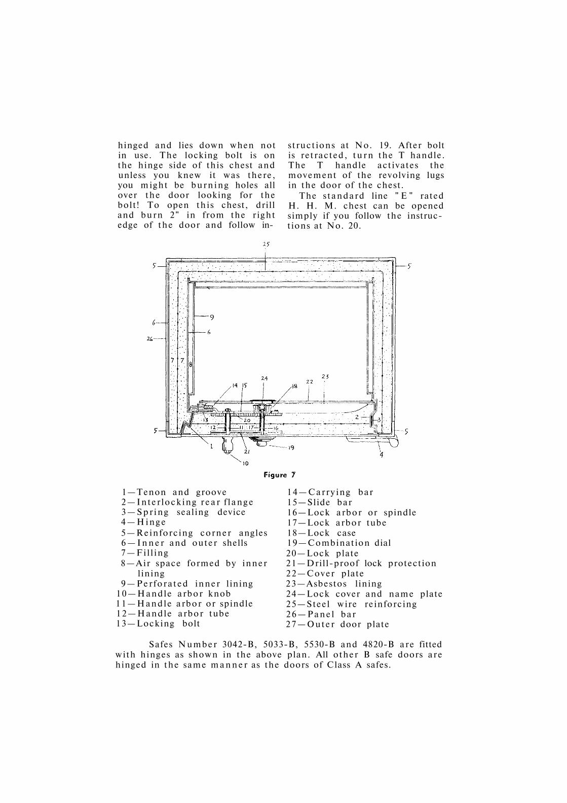
hinged and lies down when not in use. The locking bolt is on the hinge side of this chest and unless you knew it was there, you might be burning holes all over the door looking for the bolt! To open this chest, drill and burn 2" in from the right edge of the door and follow in
structions at No. 19. After bolt is retracted, turn the T handle. The T handle activates the movement of the revolving lugs in the door of the chest.
The standard line " E " rated H. H. M. chest can be opened simply if you follow the instructions at No. 20.
1—Tenon and groove 2—Interlocking rear f lange 3—Spring sealing device 4—Hinge 5—Reinforcing corner angles 6—Inner and outer shells 7—Fill ing 8—Air space formed by inner
lining 9—Perforated inner lining
10—Handle arbor knob 11—Handle arbor or spindle 12—Handle arbor tube 13—Locking bolt
14—Carrying bar 15—Slide bar 16—Lock arbor or spindle 17—Lock arbor tube 18—Lock case 19—Combination dial 20—Lock plate 21—Drill-proof lock protection 22—Cover plate 23—Asbestos lining 24—Lock cover and name plate 25—Steel wire reinforcing 26—Panel bar 27—Outer door plate
Safes Number 3042-B, 5033-B, 5530-B and 4820-B are fitted with hinges as shown in the above plan. All other В safe doors are hinged in the same manner as the doors of Class A safes.

Sericing Diebold safes light and heavy iron wall types relocker mechanism money chests
This article is devoted primarily to opening and servicing Diebold safes. There are four general types of Diebold Safes that we shall discuss in this series. While these four do not represent all of the Diebold line, past and present, they do, however, represent about 80% of the types of Diebold safes you will be required to open or service.
the component parts are housed within a lock box. The combination lock consists of four wheels and a drive wheel. The lever which contains the fence bar is connected to the slide bolt. When all the wheels are properly aligned, the fence bar drops into the gateways of the wheels and by continuing to turn the combination to the right, the slide bolt is drawn back into the lock box and open position. (See Fig. 2 ) .
The first of the old line, unlabelled Diebold safes is the heavy wall, "Severe Fire Exposure" type. The safe can be easily identified by the typical square body corners and the round door corners, (Fig. 1) . The combination dial will be marked with the Diebold name and, if the safe still bears the original paint finish, the name will probably appear across or above the door on the body architrave. The combination lock used on this model Diebold is a self contained lock, wherein all
Diebold safes can be identified by square outside corners "A and rounded dor corners " B " .
Diebold combination lock operation: Nose " A " of Lever " D " drops into drive wheel gateway " B " . Concealed fence bar " C " rests on outer periphery of wheels. Note concave edge on bolt " E " .

The combination always opens to the right, (Right to Stop) ; If all the wheels are utilized, and by that I mean if all the wheels are individualized and no two set on one number, the combination will s ta r t to the right 5 times, left four times, etc. As shown on Fig. 2, the drive cam of the Diebold lock is furthest away from the dial. The position of this drive wheel serves a definite purpose: In the event the combination dial is knocked off the safe door, and a "spindling" is attempted, the wheels will not be disturbed in such an attack because the drive wheel is being driven away from the wheel pack. The lever and bolt remain in a locked position even though the safe is spindled.
This model Diebold safe contains a hard steel drill-resistive guard plate. This guard plate is found just under the outside face plate of the door. The combination lock box is mounted on the hard steel guard plate and the heavy screws attaching the lock box go r ight through the hard plate. The screws are soft and can be drilled. Thus this hard steel guard plate is vulnerable in four locations and provides us with four access points for opening this safe. However, since the plate itself is made vulnerable by its actual
placement just behind the outside face plate, we do not need to locate the lock box screws although that method of penetration can be used also. A hard drill resistive guard plate will resist only ordinary steel drills. These plates will not resist hard steel drills. Although drilling through one of these guard plates these guard plates is possible, it is accomplished only by a great deal extra effort than in drilling an ordinary steel plate. In other words, the new hard steel drills will enable you to penetrate a hard steel guard plate but it still requires hard work and steady pressure with a a high speed drill.
I have found that when the hard guard plate is so close to the outside, a small grinder using an abrasive mount, or better still, a tapered or pointed mount, will penetrate the guard plate much quicker and with much less effort. Drill the first hole through the soft steel outside plate until the hard guard plate is reached. Run through this soft steel again, this time with a one half inch drill. This wide opening will give the grinder point a better chance to get in. Hold the grinder at 45 degree angle as it is the sides of the grinder tha t does the work and not the very tip. Holding the grinder s traight in will not accomplish much.
For quick opening, but not without damaging the lock, follow the procedure outlined in No. 21 of the Master Chart. The hard plate of the Diebold safe is 1/4 to 3/8" thick. Once you get by it, there is nothing between you and the lock, neither insulation nor obstructions to hamper you. This model Diebold does not have a re-locking device.

The way to open this safe in a more scientific manner is to penetrate the lock at No. 22, line up wheels under the fence, turn right to open. For still another scientific approach, line up the wheels at the peep hole outline in No. 23, Read the dial as you work the combination wheels around and line up all the gateways. Transfer these readings to your opening index, tu rn right to open.
Another old line Diebold safe is the light wall cousin shown above. It is younger in years, and slightly improved insofar as the door has tongue-and-groove construction. This model Die-bold safe also has square body corners and rounded door corners. The major distinguishable characterist ic that sets it apar t from the heavy wall safe is the bolt control handle. The handle on the younger model lighter wall Diebold is a drop handle, while the heavy wall Diebold has a T handle. The lighter wall Diebold also is equipped some
times with ball bearing hinges, while the older Diebold has plain hinges. The rounded corner of the new Diebold safe is not as round as the older model, and the corner is not as pronounced. The name Diebold may be found stamped on the dial hub or painted across the face of the door. (Refer to Safe Identification Article in Locksmith Ledger, March, 1953 Issue, pages 2 and 3, Figs. 3, 4, 5 ) .
This model Diebold safe uses its own make of lock but is different from the lock used on the older Diebold. The combination lock consists of a round lock box, cast iron, a set of four wheels (if hand change type) , three wheels if key change type, and a drive wheel. The drive wheel on this model safe is nearest the outside of the safe, (Fig. 5 ) .
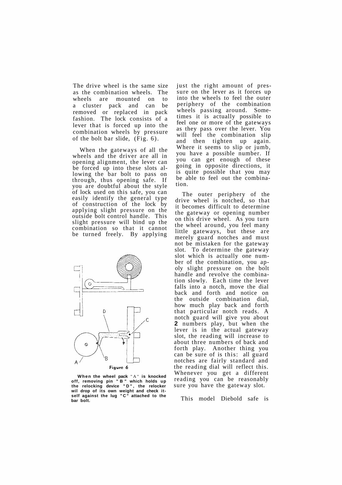
The drive wheel is the same size as the combination wheels. The wheels are mounted on to a cluster pack and can be removed or replaced in pack fashion. The lock consists of a lever that is forced up into the combination wheels by pressure of the bolt bar slide, (Fig. 6 ) .
When the gateways of all the wheels and the driver are all in opening alignment, the lever can be forced up into these slots allowing the bar bolt to pass on through, thus opening safe. If you are doubtful about the style of lock used on this safe, you can easily identify the general type of construction of the lock by applying slight pressure on the outside bolt control handle. This slight pressure will bind up the combination so that it cannot be turned freely. By applying
just the r ight amount of pressure on the lever as it forces up into the wheels to feel the outer periphery of the combination wheels passing around. Sometimes it is actually possible to feel one or more of the gateways as they pass over the lever. You will feel the combination slip and then tighten up again. Where it seems to slip or jumb, you have a possible number. If you can get enough of these going in opposite directions, it is quite possible that you may be able to feel out the combination.
The outer periphery of the drive wheel is notched, so that it becomes difficult to determine the gateway or opening number on this drive wheel. As you turn the wheel around, you feel many little gateways, but these are merely guard notches and must not be mistaken for the gateway slot. To determine the gateway slot which is actually one number of the combination, you ap-oly slight pressure on the bolt handle and revolve the combination slowly. Each time the lever falls into a notch, move the dial back and forth and notice on the outside combination dial, how much play back and forth that particular notch reads. A notch guard will give you about 2 numbers play, but when the lever is in the actual gateway slot, the reading will increase to about three numbers of back and forth play. Another thing you can be sure of is th i s : all guard notches are fairly standard and the reading dial will reflect this. Whenever you get a different reading you can be reasonably sure you have the gateway slot.
This model Diebold safe is
When the wheel pack " A " is knocked of f , removing pin " B " which holds up the relocking device " D " , the relocker wil drop of i ts own weight and check itself against the lug " C " attached to the bar bolt.

vulnerable to a "spindling" attack, because the placement of the wheel pack is behind the driver. It is possible to drive out the entire combination, but to offset this weakness an automatic re-locking device is par t of the lock. Should the wheel pack be disturbed by punching in, a t r igger finger releases a steel slide that drops down over a heavy lug attached to the bolt bar. It is not possible to draw bolts back when the re-locker has been released.
Quite often you will be called in to open one of these Diebold safes that has been burglarized. If the combination has been knocked off and the spindle driven in, you can be reasonably sure that the re-locker has been released and is checking the bolts. It will be necessary therefore, to drill for the re-locking device and lift it up to allow the bolts to pass by. Drill a 1/4" hole at point specified in No. 26 of the master code chart.
For drilling this safe when everything is in order and combination is not disturbed, drill small 1/4" hole at No. 25. You are given an al ternate here to choose from. The first way is the neatest.
The round door Diebold money chest with top opener is called the Diebold " Cashgard " of which there are many in use today. The combination lock used in this safe is the standard size square rectangular lock similar to the S & G Model 6730 and found on almost all safe cabinets. The lock bolt is hard and cannot be drilled. The round door may or may not be hard. Almost all that I have encountered have been drillable. The lock bolt is not protected
with hard inserts, and once in, you will be able to reach the bolt without any difficulty. If the outside of the door happens to be case hardened, just grind the hard skin away and proceed in with an ordinary drill. The bolt is 2 1/2" in. To open the Diebold Cashgard drill at No. 27. The safe is equipped with a re-locking device, so don't do a lot of unnecessary pounding after you have drilled your hole.
The main differences between the modern steel safe of today and the old line iron safes of years ago are as follows: Old line iron safes were constructed of heavy cast iron jams that were riveted to heavy steel plates. The jams were not ton-gue-and-groove and looked more like steps graduated down and in. The step down construction of the door jams offered little if any protection. And they may have been designed this way to give the safe the massive appearance of laminated steel. The modern labeled safe is constructed of pressed steel. The steel jams are cut and stamped out under huge presses, and all par ts are now welded together. The door jams are tongue-and-groove not only to make the heat travel further and thus cool quicker, but also to provide locks or checks so that the body of the safe and the door jams will be interlocked even when the steel has lost most of its tensile strength under red heat.
Modern safes should be referred to as pressed steel safes, and not safe cabinets. This description is more fitting and adds prestige to the product. Many have asked why the older safes used heavy steel outside plates as compared to the relatively

thin sheet steel used on modern safes today. The basic reason is that steel is an excellent conducter of heat. The thicker the piece the more heat it will conduct and hold. The thinner the steel sheet, the less heat it will hold. The modern safe of today is built primarily for fire-resistance and not, as most people believe, for both fire and burglary. The old line safes were probably built with the dual protection factor in mind, that is why they were so thick and heavy.
Figure 7 shows you a modern steel Diebold safe. The name Diebold is usually stamped on the dial grip. The style of combination lock is the ordinary box lock similar to the Yale lock and the same size. These locks are all key change locks and the cross section of this locking mechanism is shown on Figure 8. Please notice that this Diebold safe is equipped with a hard steel drill proof plate which extends beyond the combination lock box and over to and beyond
the handle lock crank assembly. The combination lock is fastened to the hard plate by four screws. The hard plate measures 4 1 / 4 " wide by 8" long and is 1/4" thick. There are two or three ways to open this safe very easily. See No. 28 and No. 29 of the master code chart. Drill 1 / 4 " holes at places indicated. The Diebold No. 900 lock measures 3 1/4" long by 2 1/2" wide.
Page 60

А—Connecting Bar P—Dial Spindle Bushing В—Washer Q—Grip C—Cap Plate R—Dial D—Two Pin Lock Crank S—Dial Ring
Assembly T—Bolt Throw Spindle E—Bolt Shoulder F—Washer U—Bolt Throw Spindle G—Lever Shoulder Screw Bushing H—Bolt Lever V—Handle Knob Shoulder I—Driving Cam W—Bolt Throw Spindle J—Lock Case Lid or Cover X—Pin К—Wheel Pack (tumblers) Y—Handle Knob L—Lock Case Z—Drill Proof Lock Plate M—Relocking Plate AA—Lock Plate Support N—Boss BB—Diebold fire-proof com О—Dial Spindle position

Meilink Safes Locking Mechanism Relocker Device
Of all the safes you may be required to work on, you will probably find the modern labeled Meilink safe is one of the toughest. Structurally, it is extremely well made and like most modern safes made today, the combination lock is well protected by a hard steel guard plate. This hard plate measures 8" long by 3 3/4" and 1 /4 " thick. The lock box screws are protected by this hard plate and an auxiliary relocking device is mounted outside and above the combination lock box. Fig. 1 shows a typical modern type Meilink safe. The name and Underwri ter 's label usually appear on the outside of the safe. A standard type S. & G. 6730 combination lock is used on all Meilink safes. The handle connector on the inside is made with a "shear-off" screw, so that if undue pressure is applied to the bolt control handle, this screw will break before any force can be applied to the combination lock.
Fig. 2 shows the bolt s t ructure and locking mechanism of a fairly modern labeled Meilink safe. You can see that the door does not have top and bottom bolts. It contains side bolts only. The heavy bars connecting to
and controlling the bolt pins are convenient to reach from the
Page 62

outside of the safe because there is no guard plate protecting these bars.
Fig. 3 shows a modern 1957 Model Meilink safe. The construction of the door and bolt mechanism is practically the same as the model shown in Fig. 2, with the exception that the relocking device is sep
arate from the lock. A heavy spring activates the relocker pin when the combination lock box cover is moved or knocked out. The relocker pin in Fig. 3 is shown in its activated position. You can see how the locking cam connector, controlled by the bolt handle, strikes this pin thus preventing the bolt mechanism from being released. In the case of a burglary, it will be
necessary to drill for this relocker pin. For single door safes drill at # 3 8 . For double door safes, drill at # 3 9 .
On examining Fig. 2 more closely, you will see that the bolt pins slide in and out of the tube socket chamber. This idea is basically good since the bolts are protected from dirt and dust from the insulation. However, as the grease in these tubes dries out, the bolts will not slide in and out as freely as they should. There are three possible ways to open the Meilink safe.
Look at Fig. 4 which gives you a detailed sketch of the Meilink lock system and relocker. These dimensions are exact and should aid you greatly. For opening single door Meilink safes drill 3/8" hole at # 4 0 . For opening
double door Meilink safes drill holes as outlined at # 4 1 . You can also use # 4 1 for drilling single door safes.

Mosler Safes OLD TYPE LIGHT AND HEAVY WALL LINE
M O D E R N P R E S S E D S T E E L L I N E
VAULT DOORS
C A U S E S O F L O C K O U T S
The largest builder of safes and vaults in the world today is the Mosler Safe Company with factories in Hamilton, Ohio. The Mosler Safe Company is also one of the oldest safe companies in existence. This company has been a family owned enterprise for four generations. The present generation, Edwin and John Mosler have added more luster to the family name than all other generations combined. The name Mosler is now synonymous with quality and prestige and is continually associated with progress in security. The nation's gold supply is stored and protected in Mosler vaults. One of Mosler's greatest achievements, perhaps, was the building of the giant safe that houses the nation's three most precious documents, The Constitution, The Bill of Rights, and The Declaration of Independence. This huge safe is in the National Archives Building in Washington, D. C.
Figure 1
You will see many Mosler safes in use today, both old and new. The older iron type safes (not labeled) were of two popular types. One model was the extremely heavy wall safe designed for severe tire hazard. This model safe (of which many are still in use) has a very thick door which measures 7" to 8"
thick and has characteristic steps in the door and jamb. The other type Mosler safe of that vintage was a light wall safe that was designed for lesser fire hazard.
The common characteristic of both models, for easy identification, is the rounded body corners and the square door corners. I like to refer to the Mosler corner as a ball shaped corner. Refer to Fig. 1 This picture shows a Mosler light wall safe. Fig. la shows front of Mosler safe. ( Note characteristic h a n d l e ) The exterior of the heavy wall safe would look much like the safe in Fig. 1. The only difference would be in the added thickness of the interior walls of the body and of the door.
The heavy wall Mosler safe uses a s tandard box type com-

bination lock with built in slide bolt. As the combination is worked, the last turn retracts the bolt into the box, allowing the handle mechanism cam to pass by. Look at Fig. 2. This model Mosler safe does not have a hard steel drill-resistive guard plate, so drilling at any point is possible. However, for the best approaches to opening this model heavy wall Mosler safe, follow instructions outlined at # 3 0 in your master code chart .
It is important the you distinguish between the two models of safes before at tempting to open them since both models use a different style of combination lock and require different methods of opening. Here is how to distinguish between the heavy
wall and the light wall safes. Apply slight pressure against the outside bolt control handle and rotate the combination dial at the same time. If you feel the combination tighten up when you force the handle over, you can deduct immediately that the safe is a light wall model. The reason for this deduction is that the light wall safe uses a style of combination lock whereby the slide bolt forces a lever up into the bottom of the combination wheels. When the wheels are in alignment the lever passes up into the gateways (slots). When the wheels are not in alignment the lever presses up into the wheels, causing drag. Now, on the heavy wall safe, pressure on the bolt control handle will not affect the free turning of the combination dial because, as you can see in Fig. 2, the pressure would not be applied directly into the combination wheels, but on the slide bolt.
Step No. 1 in opening an old line iron Mosler safe is to first determine which model it is by the handle pressure method. If it is the heavy wall model with the lock box and, slide bolt your drilling instructions are at # 3 0 . the light wall model requires a different procedure of opening which is indicated at # 3 1 of the master code chart .
The combination lock on the heavy model usually contains four wheels and a driver. Some have three however. The bolt control handle turns left to open. The combination of the light model consists of three wheels and a driver and the bolt handle tu rns to the r ight to open. The heavy wall model does not have a re-locking device, whereas the

light model does have a re-locking device.
Mosler Mosler Heavy Model Light Model
Hard plate No No Re-locking device No Yes Number of wheels Usually 4 3
Sometimes 3 Driver opens on Left to stop 34 (no auto
matic draw back or stop)
Basically, both models are soundly constructed. Although occassionally they require some service jus t as any other mechanical device, there is no apparent weakness that can be called "character is t ic" .
Always lubricate the bolt mechanism thoroughly. On several occasions we have experienced lock-outs caused by extreme dryness and lack of lubrication on the light wall model. Fig. 3, describes the type of locking mechanism used on this model safe. You can see how
the slide bolt presses into the lever, raising the lever and forcing it up into the wheels. It is probable that most of these old safes never get lubricated and as a result they get drier and drier down through the years. The day usually arrives when the dryness in the lever and slide bolt causes the mechanism to
freeze up, especially if the safe is out of use for any prolonged period.
Practically speaking, it is hard to tell during a lock-out of this type whether there is some faulty operation in the wheels or other part of the mechanism. In previous articles you have been told how to determine the number of wheels in a combination lock by the number of pickups you can feel. A cause of many, many lock-outs is abroken fly in one of the wheels. If a fly is broken, the wheel is out of operation and although the rest of the combination is functioning properly, that one wheel is still in a locked position. The first thing to do during a lockout is to feel your combination and try to determine the cause. Try to count your wheels and be absolutely sure that each wheel is operating and that no one of them has become disconnected.
In the case of a lock-out because of dryness, first feel all the wheels to make sure they are working. I always tap the bolt handle a little on all opening jobs to shake up the mechanism a little, and loosen any part that may have become jammed. Tapping on a bolt handle with a series of rapid blows will shake the lever loose on the light wall safe and enable you to open it after combination is set. It goes without saying that lubrication is the next order of business after a thorough check through the entire mechanism.
We now go to the modern Mosler safe, the Labeled pressed steel type safe. Modern type safes (other than iron safes) are often referred to as cabinet type safes. Actually, this is a misnomer, and a more suitable way to refer to these safes is
A — l e v e r Bearing; В — L e v e r ; С—Gateway; D—Dry condition at t h i s point can cause lockout; E —S l ide Bolt.

A—Expansion Joint; B—Corner Angle; С—Heat Baffle; D—Outer Plate; E— Wire Mesh Reinforcement; F—Hard Lock Plate; G-Hard Steel Guard Plate; H —Stainless Steel Lock Spindle; I—Protective Tubes; J—Hard Pins in Spindle; К— Twist Neck; L—Stainless Handle Arbor; M—Tongue & Groove Jamb; N—Jamb Anchor; O-Corrugated Heat Baffle; P—Steel Wall Anchors; Q—Perforations for Shelf Adjustments; R—Valve Door Seat; S—Exposed Fusible Stud; T—-Mosler Insulated Thermostatic Valve Door; U—Concealed Fusible Stud; V—Monolithic Insulation; W—Removable Insulated Cover over Lock; X—Locking Bolts.
"Pressed Steel Type Safes". These modern safes range through several different qualities, but the only accepted designations are the "A" label, the "B" label and the "C" label. Mosler pressed steel safes also come in these three grades. Each safe is distinctive, one does not look like the other. Each safe is built differently but they all use the same locking method. Mosler safes are equipped with two hard steel guard plates. A smaller guard plate protects the combination lock box screws. This plate is first in line as you look into the safe from the outside. Between the hard plate and the lock is insulation. The lock itself is mounted on another
hard plate. Both the bolt control handle and the combination spindle have drill resistive steel pins mounted in to prevent drilling. The handle shaft has a twist neck (weak point) so tha t if undue pressure is applied to the handle as in a burglary, the handle will break at the twist neck before any force can be wrought to the lock itself. Look at Fig. 4. (Detailed sketch of Mosler safe.)
All modern pressed steel Mosler safes built within the last twenty years use the same method of locking. The A label, В label, and С label are all alike, and a typical Mosler lock and locking mechanism is shown in Figure 5. You can clearly see

how the bolt connecting cam strikes the combination lock bolt in its locked position, preventing the bolts from releasing. When the combination lock bolt is retracted back into the box, the cam can pass by. Looking at this picture, one might be inclined to think that it would be a simple matter to open this safe by merely removing the combination bolt obstruction. This mechanism looks fairly simple, but it is well protected from the outside. You cannot drill through the safe to get at this bolt because it is protected by two hard steel plates. Both the combination spindle and the handle shaft have hard steel pin inserts which prevent drilling, and the combination dial shaft is shouldered, (larger on the outside than on the inside) to resist punching.
In the event you are called to open one of these modern Mosler safes, you have two methods of approach. Refer to # 3 2 in your master code chart. Mosler safes have no predominant weakness in construction that proves repetitive down through the years.
On double door safes made by Mosler you might find a condition whereby when both doors are closed, the r ight door bolt handle does not throw over far enough to lock the combination lock. You will notice though that while the door is held in an open position you can throw the combination lock without difficulty. You must then deduct that the trouble occurs only when the door is closed. You will notice that the middle bolt on the left hand door is slotted. This is an adjusting bolt. You can regulate the degree of play of the handle in the r ight hand door
by regulating this bolt on the left door. Quite often, however, this bolt works out too far so that when the right hand safe door is closed and the bolt mechanism is thrown over to lock, the middle bolt of the right hand door strikes up against the middle regulating bolt of the left hand door. If the bolt mechanism is not completely locked, then the position of the cam naturally is not completely up where it should be. Consequently, when turning the combination dial to lock, the slide bolt strikes up against the cam. The user will probably force the bolt to lock and in time, unless this condition is corrected, a lock-out may occur. All tha t is necessary to relieve this condition, is to screw in the regulating bolt on the left hand door.
There are two popular types of vault doors in use today. One is the old line iron or steel plate type vault door, which is not insulated, and the other is the more modern type of insulated vault door. Because of their size, and being a par t of the wall, they will often settle with the building. As the wall or building settles, the operation of the
vault door will be hampered. Locksmiths are well aware how an ordinary wood door will s tar t to bind because of building settlement. Vault doors are no exception. Unfortunately, however, you cannot plane the edges as you would an ordinary wood door. The job is much more complex, depending on the binding condition.
Settlement will throw doors out of plumb—str iking the door jamb at one end while the other end is still a fraction out. On some lighter doors it is possible to give the door a twist and bend it slightly so t ha t both top and bottom closing edges close in together. To do this, insert a wood block at the top or bottom edge of door (whichever protrudes) and twist the door by applying a lot of pressure on the
other end. The block serves as a cushion so that the door jambs will not become dented or disfigured and at the same time makes allowance for greater twist ing distance. The door will be "springy", so that before you can put a twist into it, you must push it beyond the "springback" point. The block inserted in the upper left or r ight hand corner depending on swing of door will set the door out away from the door jamb and yet still give you solid contact with the jamb. A couple of husky men can then press in on the other end of the door and at tempt to give it the slight twist it needs to close in flush all around.
Steel plate type doors are more easily twisted than the insulated type. On steel plate doors you might find the condition whereby the edge of the door strikes the edge of the frame and yet the door is plumb. Check first to see if the hinges
are loose or possibly worn. In many cases hinges wear down from lack of oil so that the door strikes the bottom. Build up the hinges by placing thin washers between the two halves of the hinge and raise the door back up to its original position. If they are all right, then the only alternative to eliminate this str iking condition is to grind the door with a portable grinder at the point of friction. Be sure to smooth down the ground area with a file or emery paper because the grinder will leave a rough edge and cause possible hurt to someone passing the door or accidentally coming into contact with it. These rough edges can cause damage to clothing also.
At the present time, the installations of Mosler non-grout insulated vault doors have become quite common throughout the country. This type door can be adjusted for smooth operation by the following method: First , remove the inside clasping angles. Adjust the screws at the sides and top edges of the door frame in the direction required to relieve the binding of the door when it swings in to the frame. Then, tighten the lock nut on each adjusting screw and replace the inside clasping angles..
In some cases, one side of the frame may have to be raised. If so, place the required thickness of shim under tha t side between the door sill and the floor; then tighten the adjusting screws and lock nuts.
Do NOT open the door wide when the inside clasping angles are removed unless the top adjusting screws are tight. This is to prevent the entire frame from falling forward out of the wall opening!

techniques of safe servicing york national, protectall, pittsburgh, and rand safes
York Safes
The York safe of today has the same styling features of the Diebold safe, an understandable similarity since Diebold, Inc., has taken over the York line.
Prior to this, York had built its own distinctive safe, shown in Figure 1. Although this safe is not manufactured, it still is in use throughout the country since it is a well-made model.
Some of these safes are equipped with a set of heavy re-locking pins that are activated when the combination lock is
punched in during an unauthorized entry. An exposed view of the door interior, illustrating these relocker pins, is shown in Figure 2. Note that there are four bolts in the door — the two center bolts are the relockers, while the top and bottom bolts are the active locking bolts controlled by the outside handle.
The relocker pins are held in place by the back cover of the door; thus, if the combination lock is punched and the back cover disturbed, the relocker will shoot out to relock the door. Unlike other relocking devices, that is those that freeze the control handle when activated, the relocking mechanism shown here for the York safe, permits the handle to be operated. However, the relocker pins prevent the door from being opened!
If you are called upon to service a burglarized safe of this type, and you note that the handle can be operated but the door cannot be opened, you will know immediately that the relocker has been released. It then

is necessary to drill for these pins. Drilling instructions are given in Step No. 45 of your Drill Chart.
To service this type safe under normal conditions follow instructions given under Step No. 46 in your Drill Chart. In this operation, you must use extreme caution not to do any unnecessary punching or probing or you will set off the relocker.
York Round Door Depository Chest
The door of the early model York round door chest is not hinged and does not pull out away from the door jam as the doors on most chests of this type. This style door rotates 180° to its opened or closed position. When the rotat ing action takes place, a half circle cutout in the door is lined up with a half circle cutout in the chest to permit access into the interior. Thus, when the chest door is closed, the hole cutout which is provided in the side of the chest, is covered as shown by the dotted lines in Figure 3.
The major service problem on this style of chest is to determine the manner in which to remove the door for repair or combination changing. This can be done by using the following method: Rotate the door to its half-open position and reach be-
hind the door to locate the bol t "C" shown in Figure 3. This bolt is attached to the inner side of the door and serves as a stop to control the door rotation. It is held in place by a stiff spr ing; there also is a pin inserted through the bolt at a right angle. You will feel this as you reach behind the door; draw this pin back and the entire door will pull away.
The combination locking bolt, " B " in Figure 3, on this style chest is located to the right of the door as you face the chest. A quarter round hard plate is provided to protect the locking bolt area (See "A" in Figure 3 ) . A variation of this occurs with chests that open from the top — on these models, the guide and stop bolt is on the right side and the combination locking bolt is on the upper left side.
National Safe
A National Safe can be identified easily by its lock-handle relationship — all models have the the combination lock dial placed above the handle, as illustrated in Figure 4. The combination
lock used on these safes is a standard Yale OB series lock, using a weighted lever that drops into the wheels when they are aligned. As the lever drops,

the bolt bar is permitted to pass to its opening position. An exposed view of this lock is shown in Figure 5. To service a lockout on this safe, drill according to the instructions given in Step No. 48 on your Drill Chart. There is no hard plate.
Protectall Safes
Protectall manufactures a safe model that also has the combination dial located above the bolt control handle. The lock used in these particular models is a standard type combination lock with the retractable bolt operating within a lock case. However, when this lock "C" as in Figure 6, is installed, it is in an inverted position with the bolt " D " facing downward to bind against the handle cam " E "
Figure 6 also shows the hard plate "A" that protects the lock from drilling.
This safe also is equipped with a relocking device, illustrated by arrow " B " in Figure 6. When it is activated, the relocker shoots downward to bind into the bolt. Dimensions of this relocker are given in Step No. 49 of your Drill Chart, which also explains the instructions for drilling.
Pittsburgh Safes
Safes manufactured by the Pit tsburgh Safe Company can be identified easily by the firm name stamped on the combination lock dial. A Pit tsburgh safe uses a locking mechanism in which the operating action presses a lever up into the combination wheels. When all the gateways are in alignment, the lever is pressed up far enough to permit the bolt bar to slide under the wheels into an open position. In the event a safe of this type is jammed, you will find in your checking out procedure that pressure applied to the bolt control handle will cause the combination to bind and turn hard. Even without knowing what make of safe this is, the characteristic feel of a binding combination should indicate to you where to drill. For checking purposes, however, in the drilling procedure, refer to Step No. 50 in your Drill Chart.
Remington Rand Safe Cabinet
The modern style Remington Rand safe cabinet is identified by a prominent characteristic — the combination dial and bolt control handle is fashioned in one compact unit (See Figure 7 ) . Generally speaking, this particular safe cabinet is very diffi-
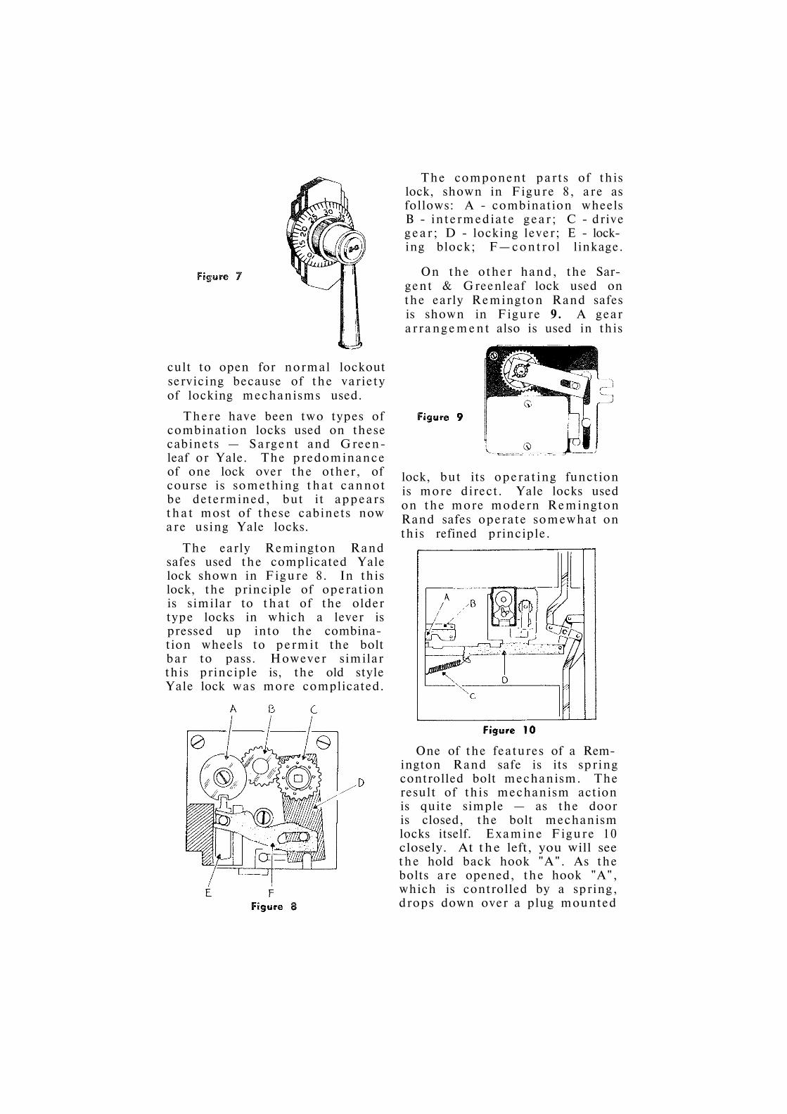
cult to open for normal lockout servicing because of the variety of locking mechanisms used.
There have been two types of combination locks used on these cabinets — Sargent and Green-leaf or Yale. The predominance of one lock over the other, of course is something that cannot be determined, but it appears that most of these cabinets now are using Yale locks.
The early Remington Rand safes used the complicated Yale lock shown in Figure 8. In this lock, the principle of operation is similar to that of the older type locks in which a lever is pressed up into the combination wheels to permit the bolt bar to pass. However similar this principle is, the old style Yale lock was more complicated.
The component parts of this lock, shown in Figure 8, are as follows: A - combination wheels В - intermediate gear; С - drive gear ; D - locking lever; E - locking block; F—control linkage.
On the other hand, the Sargent & Greenleaf lock used on the early Remington Rand safes is shown in Figure 9. A gear arrangement also is used in this
lock, but its operating function is more direct. Yale locks used on the more modern Remington Rand safes operate somewhat on this refined principle.
One of the features of a Remington Rand safe is its spring controlled bolt mechanism. The result of this mechanism action is quite simple — as the door is closed, the bolt mechanism locks itself. Examine Figure 10 closely. At the left, you will see the hold back hook "A". As the bolts are opened, the hook "A", which is controlled by a spring, drops down over a plug mounted

on the bolt " D " to hold the bolts in an open position. When the door is closed, the plunger " B " rams against the door jam, releasing the hook so that the bolt bar can spring back to lock.
It is reasonable to assume that the safe will not lock by itself if the bolts lose their alignment with their receiving holes since the control spring is not strong enough to compensate for such abnormal conditions. However, the mechanism can be operated manually if the automatic locking mechanism does not function according to its own design.
A hard steel guard plate is used to protect the combination mechanism used on these safes so that several different methods of servicing lockouts can be used, depending on the style of lock. Instructions for this are given in Step No. 51 of the Drill Chart.
Safe Deposit Boxes
There are several methods that can be used to service lockouts on safe deposit boxes. Since some banks will not want the door of the box drilled, it will be necessary to gain entrance through the nose of the lock. A nose extractor tool is available through locksmith supply houses for this purpose, and it permits you to perform the work without disfiguring the face of the door.
In essence, the tool is used as follows: a small hole is drilled into the nose of the lock and this hole is tapped and threaded. A coupling then is placed over the nose so that a turn nut can be screwed into this hole. A pulling pressure then is created to extract the nose from the lock.
Once the nose is out, you can perform either of two opera-
tions. First , pull the door with a door puller tool. This method ruins the lock but it saves the door. Second, on some locks, you can reach into the lock with a probe and slide the bolt back to open the door. Since safe deposit box locks are always dual controlled, it is necessary to set up the lock with the guard key before at tempting to draw back the bolt with the probe.
Another popular method of servicing lockouts on safe deposit boxes is to drill into the door to remove the hinge screws. This method is quick and time-saving, but it cannot be used in every circumstance since some banks will not want the door to be drilled. If you do not know where to drill for the hinge screws, open a similar box and measure the necessary distances. Then, t ransfer the measurements to the locked box and pre-are for the drilling operation.
Before drilling however, examine the hinge on the open box to see if the box can be opened in this manner. Some hinges are screwed in from the back or narrow side of the door so that drilling out the front screws will not help. In these cases, you can drill out the

screws holding the lock to the door. The necessary dimensions must be measured from the open box so tha t a template can be made to properly indicate the screw positions for drilling.
Some of the older type safe deposit locks contain only four or five levers and, although they are dual controlled locks, they
can be picked after the lock is set up by the guard key. It is unwise to perform this, however, in front of a customer, since it is imperative that he retain full confidence in the security of his box. Bank officials usually object to this practice since they do not want customer confidence shattered.

Round Door Money Chests
CAUSES OF LOCKOUTS
YORK, D IEBOLD, M O S L E R , H-H-M CHESTS
Round door money chests are finding their way into the consumer market more and more each passing year. Supermarkets, gas stations, mill outlets, automobile sales agencies, theatres, motels, res taurants , etc., etc., are only a few of the types of businesses that are now using round door chests. Any firm doing a large volume cash business requires this type of protection against hold-up and burglary. The reason for the big shift to the round door chest is, of course, insurance savings. The better the safe, the better the risk and the lower the rate of insurance. Here is a typical example: If a man operates a supermarket in Rhode Island and carries a $5000 Mercantile Burglary Insurance Policy, it would cost him $215.00 a year if he is using an ordinary fire resistive safe. If he changes over to an " E " rated round door money chest, the same amount of coverage will cost him only $86.25. This represents a savings of $128.75 a year.
Insurance companies know the value of proper cash protection and they offer these large insurance premium savings to those people who use round door chests. In order to qualify for the " E " rate a safe must be of round door construction, thickness of door to be no less than 1 1/2", and checked by a combination lock. The body of the chest must be at least 1" thick solid steel. It is not required that the door of the chest be case hardened nor the body of the chest be case hardened and as a result many of the chests being produced today can be drilled very easily. As a result some of these chests can actually be opened much quicker and easier than an ordinary fire - resistive sheet metal safe equipped with a hard steel guard plate.
Aside from an ordinary lock breakdown, there are several reasons why a round door chest will not open. Many users of these chests stuff money into cloth or canvas bags and place these money bags into the chest. Sometimes a corner of the bag will get jammed in the door be-
Figure 1
Cloth bags and coins jam at " A " , while rust on uncoated surface " B " can freeze door.

tween the door jam, as the door is closed and revolved to lock. (See Fig. # 1 ) . The tolerance or fit of these round door chests is extremely close, so close in fact that a thin piece of paper will not fit between, let alone a cloth bag ! If the bag is jammed in, no amount of muscle power will free the door to open. If the door of the chest is closed full way, the combination lock will function flawlessly and pull back to stop, but the door will refuse to budge.
There is a simple answer to this problem. First, do not pound on the handle grip thinking you are going to force the door to revolve open. The result will probably be a broken handle. Take a good grip on the handle and force in the opening direction, up. With this force applied, at the same time rap the door a series of medium pressure blows at different locations of the door. The vibration of the hammer blows will s tar t the door in motion as you pull up. Continue this action until the door opens.
Not only do cloth bags get jammed but also a thin coin such as a dime. You can usually tell when the re is someth ing lodged between the door and jam of a round door chest. Here are two c l u e s : 1—When the position of the revolving door is half open and half closed, and dead t ight ; 2.—When the door is full way and the combination lock fully releases. (If there is something lodged in between, there is absolutely no play or movement in the door. Normally, there is slight back and forth play.)
If a chest is not opened frequently, or in the case where a man stops using his round door chest altogether and it stands idle for a year or more, it probably will not open for him — especially if the safe is located in a damp or humid place. The edges of the door and the door jam are not painted or coated for protection against rust. Rust formation, therefore, occurs quickly. You will notice tha t even on chests that are used daily, the surfaces are dirty and reddish with thin rust formation. Since these round door chests employ "screw wedge" revolving action with but 10 thousandths of an inch tolerance, it does not take much rust to freeze a door shut. A combination lock is not likely to freeze because the component parts are made of brass or plated zamac. As a result, a chest will function as far as the combination lock goes, but the door will not give because of the rust.
These doors can become unbelievably tight, but by seeping penetrat ing oil around the opening and by using the hammer vi-
" А " — Relocking Pins; " В " — Bolt.
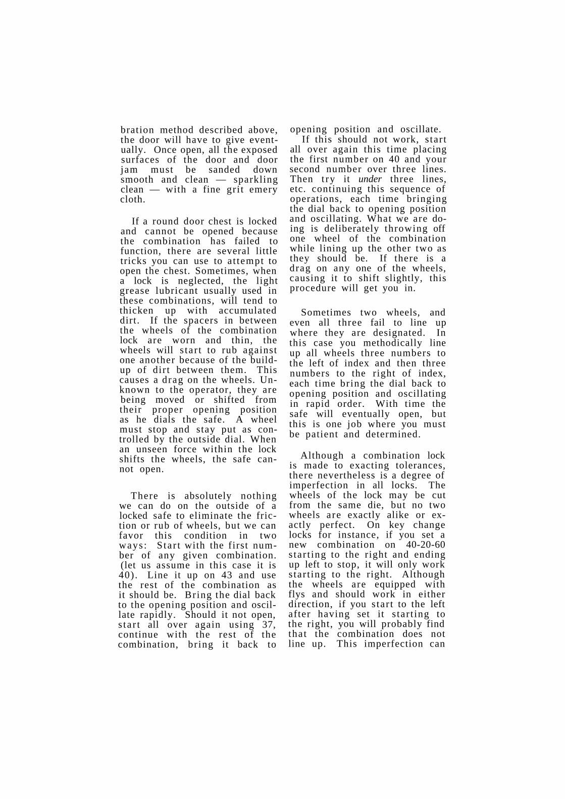
bration method described above, the door will have to give eventually. Once open, all the exposed surfaces of the door and door jam must be sanded down smooth and clean — sparkling clean — with a fine gri t emery cloth.
If a round door chest is locked and cannot be opened because the combination has failed to function, there are several little tricks you can use to a t tempt to open the chest. Sometimes, when a lock is neglected, the light grease lubricant usually used in these combinations, will tend to thicken up with accumulated dirt. If the spacers in between the wheels of the combination lock are worn and thin, the wheels will s ta r t to rub against one another because of the buildup of dir t between them. This causes a drag on the wheels. Unknown to the operator, they are being moved or shifted from their proper opening position as he dials the safe. A wheel must stop and stay put as controlled by the outside dial. When an unseen force within the lock shifts the wheels, the safe cannot open.
There is absolutely nothing we can do on the outside of a locked safe to eliminate the friction or rub of wheels, but we can favor this condition in two ways : S ta r t with the first number of any given combination. (let us assume in this case it is 40) . Line it up on 43 and use the rest of the combination as it should be. Bring the dial back to the opening position and oscillate rapidly. Should it not open, s ta r t all over again using 37, continue with the rest of the combination, br ing it back to
opening position and oscillate. If this should not work, s tar t
all over again this time placing the first number on 40 and your second number over three lines. Then t ry it under three lines, etc. continuing this sequence of operations, each time bringing the dial back to opening position and oscillating. What we are doing is deliberately throwing off one wheel of the combination while lining up the other two as they should be. If there is a drag on any one of the wheels, causing it to shift slightly, this procedure will get you in.
Sometimes two wheels, and even all three fail to line up where they are designated. In this case you methodically line up all wheels three numbers to the left of index and then three numbers to the right of index, each time bring the dial back to opening position and oscillating in rapid order. With time the safe will eventually open, but this is one job where you must be patient and determined.
Although a combination lock is made to exacting tolerances, there nevertheless is a degree of imperfection in all locks. The wheels of the lock may be cut from the same die, but no two wheels are exactly alike or exactly perfect. On key change locks for instance, if you set a new combination on 40-20-60 s tar t ing to the right and ending up left to stop, it will only work s tar t ing to the right. Although the wheels are equipped with flys and should work in either direction, if you s tar t to the left after having set it s tar t ing to the right, you will probably find that the combination does not line up. This imperfection can

work in your favor however, not only on key change locks, but on hand change locks as well.
Here is a little trick that I quite often use during a lockout, on combination l o c k s equipped with flys. If the customer has always used his combination s tar t ing to the right as in the following example, R-4-20 L-3-40 R-2-60 Left to stop, the combination will undoubtedly show a degree of wear in the wheels as operated in the above sequence for any prolonged period of time. The pins and flys tend to wear in together and even the dir t seems to settle in a part icular pattern. Star t ing your combination to the left and add the extra turn on the end, thus reversing the entire proceedure as in the following example: L-4-20 R-3-40 L-2-60 R-l-Click L to stop, you will be surprised to see that the safe opens. In short, after having tried a "gummed up" combination in the correct procedure, and it fails to open, t ry it in reverse. This simple trick has worked many times for me.
One of the better round door money chests is the York chest shown in Fig. 3. The door of the chest is hard and very difficult to penetrate with a carbon tipped drill. The chest is equipped with two sets of re-locking pins held in place by a retainer plate fastened to the lock case cover. When the lock is punched through and the cover is moved away, the pins shoot into a receiving well in the door jam.
The gateways of the wheels line up directly on top or at 12:00 o'clock to open. The lever
is controlled by a small fine spring, and if this spring loses its tension or breaks, the lever will drop by gravity.
The outside of the chest door is equipped with a large r ing for handling (see Fig. 3) . This r ing housing is mounted to the door by four heavy screws. To open this type chest, first remove the ring housing and swing the housing with hinges attached, to one side. By doing this you now have access to the face of the door without any obstructions. Follow instruction outlined at #36 of the drill chart for opening this chest.
In Part I, screws " A " hold door r ing. " B " in Part II shows the double relocking bolts, the top pair is spring mounted. " C " in Part III indicates the position of the bolt.

The Diebold Cashgard chest #1180 is very widely used. (See Fig. 4 ) . The chest is encased
in a steel cladded concrete block. This is a drop head or top opener type of chest. The combination dial is detachable and
a close up of the dial is shown in Fig. 5. The door of the chest is case hardened but can be penetrated. Grind away the hard surface and proceed to drill in as outlined in #27 of the drill chart. The combination lock is very similar to the S & G Model No. 6730 with the exception that the bolt is a little longer and is hardened steel. The bolt is found 2 1/4" down in the door.
The Mosler round door chest is also very popular today and a typical Mosler chest is shown in Fig. 6. Mosler combinations s tar t to the right and end up left to stop. The combinations are made up of three wheels and a driver. The round locking bolt is equipped with a built in relocker that is held in place by a
hook slide in the box of the lock. See Fig. 7. If the lock is punched in, the hook slide pulls away from the round bolt allowing the plunger within the bolt to spring out and then back into the plunger post. The tension on the spring is very strong and forces the entire locking bolt over into the locked position. To open a Mosler chest follow instructions outlined in #37 of the drill chart.
Figure 4
Cut-away view Diebold No. 1180 vertical Cashgard chest.
Figure 5
Diebold removable Combinat ion lock.
Figure 7
Mosler combination lock: A — S p r i n g forcing plunger againist hook; В — C h a n nel; С — P l u n g e r ; D — P l u n g e r post; E Lock case; F — S p i n d l e .

The door of a Mosler round door burglar-resistive chest is case hardened. The locking bolt is further protected from the front and the side by hard steel pins implanted in the door and also into the door jam as shown in Fig. 8. The hard steel pin inserts are in the door jam to protect the locking bolt from being punched in from the side of the safe. The chest is very well constructed and nothing has been spared by way of quality to make this one of the finest burglar-proof chests in the world today.
T h e Herr ing - Hall - Marvin round door chest is locked by a three wheel S & G Model #6730
combination lock. The combination s tar ts left and ends right to stop. A typical H. M. M. chest is pictured at Fig. 9. The handle of the chest is screwed on from the outside and often, these
screws become loose and even off, especially if the chest is used constantly. The door of the H. H. M. chest is case hard-hardened on the front side but occasionally you will find tha t they can be drilled. To open the H. H. M. Chest, follow instructions outlined at #20 of the drill chart .

Vault Doors-- Grout and Non-Grout types
E X P L A N A T I O N O F F E A T U R E S
M A L F U N C T I O N I N G DOORS
It has been asked of me many times, what is the difference between a grout type vault door and a non-grout type vault door. Also, what is the purpose or advantage of the non-grout vault door, and how it differs from the grouted door. A grouted door simply means, that the frame of the door is first set into a rough opening, whereupon the grout (another name for poured cement) is poured through an opening above the door and allowed to work down and around the frame. When the cement solidifies, the frame is bonded to the wall. The vault door then becomes a permanent part of the building wall.
A non-grout type vault door differs in tha t the door is clamped to the wall with prepared opening by two side flange clamps and a top flange clamp. The wall opening is made to ex
act measurements, thus eliminating the use of grout. The vault door is inserted into this opening and then the three inside flanges are attached and bolted tightly, clamping the door frame
Mosler six-hour insulated vaul t door installed without grouting. A A — P l a s t e r ; A—Side flange c lamp; В—Clamp Bolt; С—Escape Device Handle ; D—Lag Bolts into cement wall; E—Vaul t Wal l ; F — In su l a t i on ; H—Wi r e Mesh.
D O

and jam to the wall. Fig. 1 describes a typical non-grout vault door. You easily can see how the clamps lock the vault to the wall. The flanges are long continuous steel clamps, the same height of the door frame. The top flange (not shown on the drawing) runs the full width of the door frame. You can see further that the vault walls are completely finished even to the plaster and paint before the door is put into place.
The non - grout vault door offers many advantages over the grouted-in type. First , it does not become a permanent part of the building. It can be readily removed by removing the flange plates. Should the building settle and the door binds because of the settlement, the vault can be easily adjusted and re-aligned to compensate. The installation costs are greatly reduced and the chances of finish disfiguration from plaster, paint, grout, etc. are completely eliminated.
You will further notice on examining Fig. 1, tha t there is an inside handle. This is an escape device. Should a person be locked inside a vault at night, or should he be forced inside by burglars, easy escape is provided, by merely turning the bolt control escape handle and opening the door from the inside.
There are many doors in use in older buildings tha t are not insulated. These are called steel plate vault doors. They are easily recognizable because they have a vestibule with two inner (split) doors controlled usually by a key lock. Because theee older type doors are not insulated, they cannot be trusted to protect the vault contents
against fire. Also these heavy steel plate doors conduct heat rather than retard it. The picture in Fig. 2 shows how the steel door warps and twists out of shape when fire strikes it. Usually, the vault walls, floor and roof are of sound fire-proof construction on these old vaults, but the old steel plate doors are inadequate. When you see something like this, you should set your sights towards selling the owner a new vault door. You should explain the hazard that exists with the obsolete vault.
There are many makes of vault doors in use today, both the old line steel plate type and the more modern pressed steel type. Mosler, Diebold, Hall, Carey seem to be more numerous in some par ts of the country, especially in New England. Steel plate Mosler vault doors use two different types of combination locks. The standard lock box type with retractable bolt, and round lock with the up-shoot lever. Before at tempting to open one of these vault doors, de-
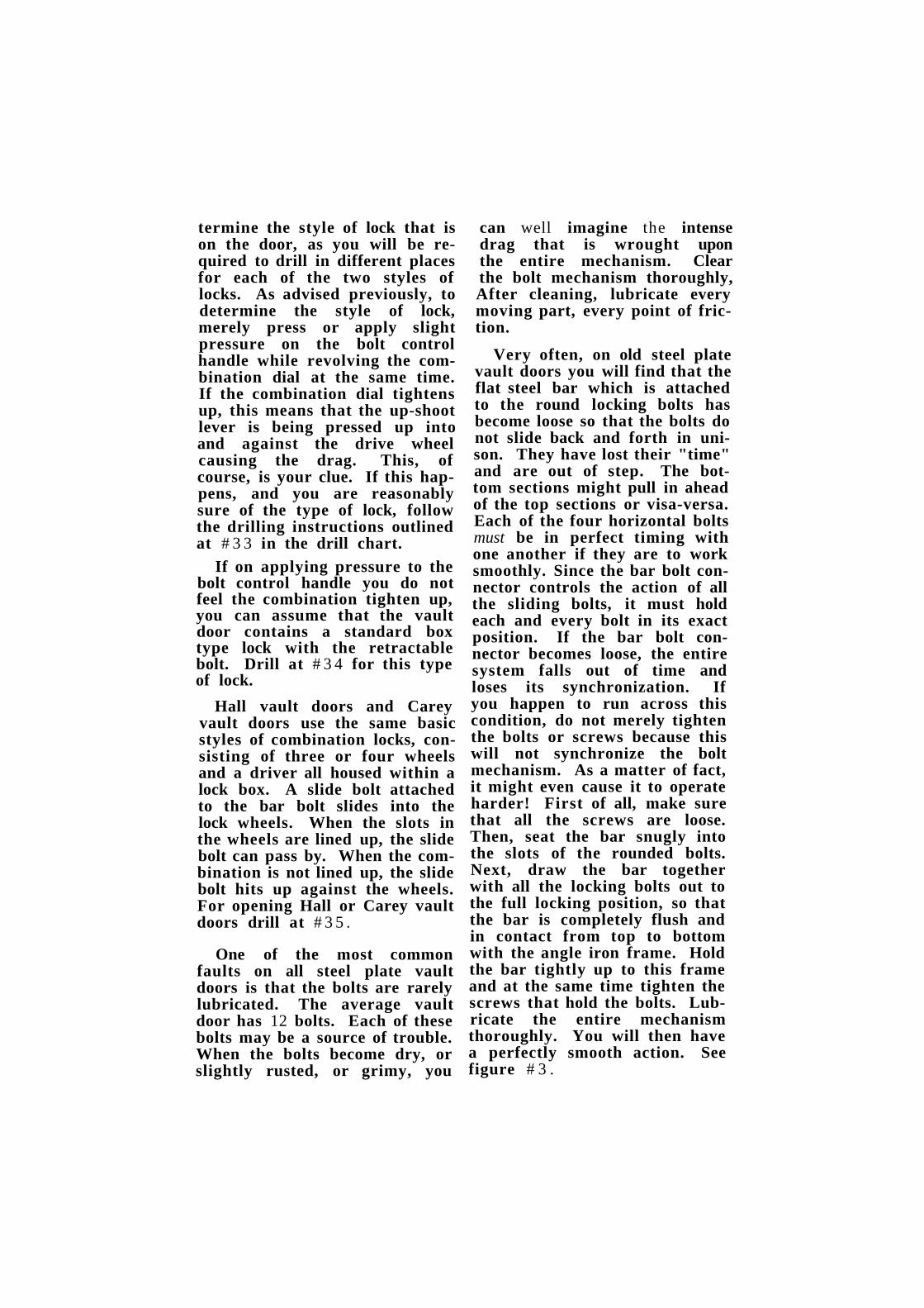
termine the style of lock that is on the door, as you will be required to drill in different places for each of the two styles of locks. As advised previously, to determine the style of lock, merely press or apply slight pressure on the bolt control handle while revolving the combination dial at the same time. If the combination dial tightens up, this means that the up-shoot lever is being pressed up into and against the drive wheel causing the drag. This, of course, is your clue. If this happens, and you are reasonably sure of the type of lock, follow the drilling instructions outlined at # 3 3 in the drill chart.
If on applying pressure to the bolt control handle you do not feel the combination tighten up, you can assume that the vault door contains a standard box type lock with the retractable bolt. Drill at # 3 4 for this type of lock.
Hall vault doors and Carey vault doors use the same basic styles of combination locks, consisting of three or four wheels and a driver all housed within a lock box. A slide bolt attached to the bar bolt slides into the lock wheels. When the slots in the wheels are lined up, the slide bolt can pass by. When the combination is not lined up, the slide bolt hits up against the wheels. For opening Hall or Carey vault doors drill at # 3 5 .
One of the most common faults on all steel plate vault doors is that the bolts are rarely lubricated. The average vault door has 12 bolts. Each of these bolts may be a source of trouble. When the bolts become dry, or slightly rusted, or grimy, you
can well imagine the intense drag that is wrought upon the entire mechanism. Clear the bolt mechanism thoroughly, After cleaning, lubricate every moving part, every point of friction.
Very often, on old steel plate vault doors you will find that the flat steel bar which is attached to the round locking bolts has become loose so that the bolts do not slide back and forth in unison. They have lost their "time" and are out of step. The bottom sections might pull in ahead of the top sections or visa-versa. Each of the four horizontal bolts must be in perfect timing with one another if they are to work smoothly. Since the bar bolt connector controls the action of all the sliding bolts, it must hold each and every bolt in its exact position. If the bar bolt connector becomes loose, the entire system falls out of time and loses its synchronization. If you happen to run across this condition, do not merely tighten the bolts or screws because this will not synchronize the bolt mechanism. As a matter of fact, it might even cause it to operate harder! First of all, make sure that all the screws are loose. Then, seat the bar snugly into the slots of the rounded bolts. Next, draw the bar together with all the locking bolts out to the full locking position, so that the bar is completely flush and in contact from top to bottom with the angle iron frame. Hold the bar tightly up to this frame and at the same time tighten the screws that hold the bolts. Lubricate the entire mechanism thoroughly. You will then have a perfectly smooth action. See figure # 3 .

You may have a condition where you cannot lock a vault door because the bolt mechanism does not seem to throw over far
enough to le t you turn the combination dial. I have known of some mechanics who have looked for hours for the source of this trouble. They will file, grind, tighten, loosen . . . they do everything but the right thing. How simple it really is when you know where to look for the
trouble! There is a bolt receptacle hole in the bottom sill of almost all steel plate type vault doors. This hole is a catch all for dirt, dust, chips, and foreign bodies of every description. Dirt keeps getting packed into this hole by the plunger action of the bottom bolt. One day the packed in dirt does not permit the bottom bolt to lock in all the way. This obstruction reflects back into the entire mechanism so that it is impossible to throw the combination when the door is in the locked position. Clean out this hole. You will be amazed how much comes out of it. Then try your door. You will see that it now works perfectly.
All these old vault doors are grouted in. Usually when the building settles, the free operation of the doors of these old vault doors is greatly affected. The handiest tool you can own for vault door work is a disc grinder, for when any part of the door strikes the frame, you can shave off just the right amount to get the door to seat in smoothly again.

Exploded Lock Viev T MP series key changing combination Lock

Manufactured by Sargent & Creenleaf,
Rochester, N . Y .

Exploded Lock Viev 6709 series Combination Lock
HAND CHANGING
Manufactured by Sargent fir Greenleaf, Rochester, N. Y.
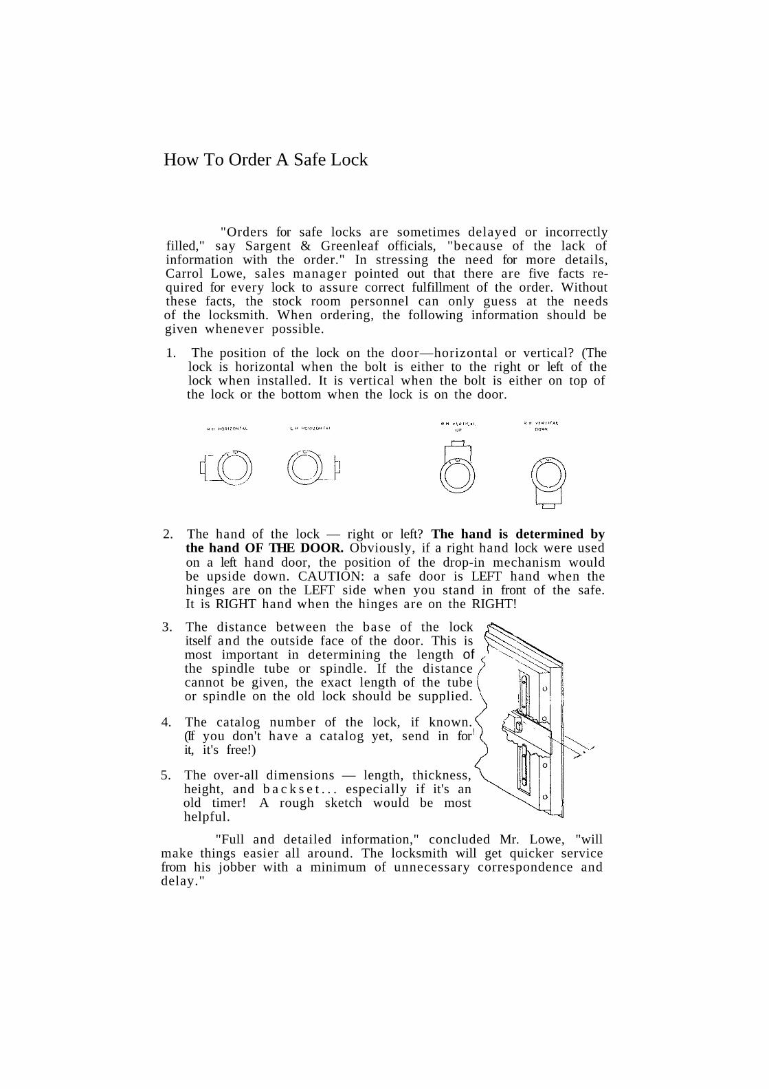
How To Order A Safe Lock
"Orders for safe locks are sometimes delayed or incorrectly filled," say Sargent & Greenleaf officials, "because of the lack of information with the order." In stressing the need for more details, Carrol Lowe, sales manager pointed out that there are five facts required for every lock to assure correct fulfillment of the order. Without these facts, the stock room personnel can only guess at the needs of the locksmith. When ordering, the following information should be given whenever possible.
1. The position of the lock on the door—horizontal or vertical? (The lock is horizontal when the bolt is either to the right or left of the lock when installed. It is vertical when the bolt is either on top of the lock or the bottom when the lock is on the door.
2. The hand of the lock — right or left? The hand is determined by the hand OF THE DOOR. Obviously, if a right hand lock were used on a left hand door, the position of the drop-in mechanism would be upside down. CAUTION: a safe door is LEFT hand when the hinges are on the LEFT side when you stand in front of the safe. It is RIGHT hand when the hinges are on the RIGHT!
3. The distance between the base of the lock itself and the outside face of the door. This is most important in determining the length of the spindle tube or spindle. If the distance cannot be given, the exact length of the tube or spindle on the old lock should be supplied.
4. The catalog number of the lock, if known. (If you don't have a catalog yet, send in for it, it's free!)
5. The over-all dimensions — length, thickness, height, and b a c k s e t . . . especially if it's an old timer! A rough sketch would be most helpful.
"Full and detailed information," concluded Mr. Lowe, "will make things easier all around. The locksmith will get quicker service from his jobber with a minimum of unnecessary correspondence and delay."

Do you have these technical books in your reference library?
S H O R T T R I C K S T h i s handy assor tment of trade t r i c ks i s a real t ime saver. Covers key-in-knob locks, safes, etc. T h e r e ' s a section showing how to make a picking sp inner that w i l l correct any e r r o r s made in picking a cyl inder in the wrong direct ion. T B 7 0 5
T E C H N I C A L T I P S Revised edit ion including informat ion to a s s i s t you in becoming a real p ro fess iona l . Exploded v iews including service notes on S & G padlock 8 0 8 8 , S & G Panic B o l t s , Schlage D85 PD and the Yale 5 4 0 0 and others . T B 7 0 6
TECHNICAL HINTS J u s t what the name implies! T h i s book is loaded with practical t ips and ideas that will "make money" for you. It g ives you easier and faster ways to do difficult jobs. And it tel ls you all about B e s t removable cores and Corbin master ring cyl inders. T B 7 0 3 R
L O C K S M I T H ' S N O T E B O O K Revised edit ion fu l l of in format ion you can use in everday work. T h i s book includes ins t ruc t ion on how to f i t keys to Ace locks, techniques of impress ion ing locks and exploded views of Adams Rite locks, Har-ioc and others . T B 7 1 0
WRITE FOR A COMPLETE LIST OF OUR
THE LOCKSMITH PUBLISHING CORP.
Park Ridge, Illinois 60068

Do you have these technical books in your reference library?
EXPLODED LOCK ViEWS VOL. I Forty of the most popular key in the knob locks completely dismantled and shown in correct pos i t i ons so that you can see how they are assembled- Also service notes and special i ns t ruc t ions . T h i s is one of the most valuable books ever publ ished for l ocksmi ths . W i l l save you hours of t ime. T B 7 2 3
EXPLODED LOCK VIEWS VOL. 2 T o continue your f i le of Key in Knob locks. T h i s second volume includes all of the later locks not shown in Volume 1. Padlocks and panic exit devices also are covered. All locks are shown in the typical "exploded" fashion giving exact re la t ionship and funct ion. T h i s book i s a M U S T for the busy locksmi th ! T B 7 2 4
EXPLODED LOCK VIEWS VOL. 3 Here's the latest in the Exploded Lock View S e r i e s . Volume 3 contains the new locksets not included in Volumes 1 and 2. T h e r e ' s the new push-button lock, the Yale Ant i-Manipulat ion Combination Lock, the Safety Alarm Lock and many others. T h i s book, with Volumes 1 and 2, gives you the best and latest in lock-set serv ic ing. T B 7 2 5

Do you have these technical books in your reference library?
KNOW HOW - A complete and up to date refer
ence for s o l v i n g many of the " s t i c k y " l o c k s m i t h
p r o b l e m s . T h i s book i n c l u d e s m e t h o d s f o r i m -
p r e s s i o n i n g the GM s idebar lock, key i n f o r m a t i o n
on Columbia f i l e cabinets, A r r o w wafer t u m b l e r
c y l i n d e r s and codes f o r 1 9 6 8 GM t ry-out key
s e t s .
T B 7 3 5
MASTER K E Y I N G ( B R U S H S Y S T E M )
Describes var ious methods used in sett ing up master
key s y s t e m s . Warded, disc and pin tumbler s y s t e m s are
shown. Mainly i l l u s t r a t e s the pr incip les behind the
s y s t e m s involved, rather than presenting forma! charts
and tables. It is wr i t ten by a l o c k s m i t h , for the lock
s m i t h . W i l l inst ruct you in wr i t ing out your own s y s
tems.
TB730
M A S T E R K E Y S Y S T E M S
T e l l s you how to plot and set up master key s y s t e m s f r o m the s i m p l e s t to the most complex. S h o w s you how to avoid interchanges. E x p l a i n s the s y s t e m s used by manufacturers to achieve maximum changes. TB731
А В C's OF L O C K S M I T H I N G
A technical book for the beginning l o c k s m i t h . De
s c r i b e s how to make keys for cy l inders, padlocks,
t r u n k s , sui tcases, etc. It also describes br ief ly how to
make keys by i m p r e s s i o n , how to open doors in emer
gencies, etc. An excellent book for the man you are
breaking in.
T B 7 3 2
WRITE FOR A COMPLETE LIST OF OUR TECHNICAL AND REFERENCE PUBLICATIONS:
THE LOCKSMITH PUBLISHING CORP. 850 Busse Highway
P a r k Bidge- I l l i n o i s 60068
I E L P F U L M E T H O D S he name is r ight! You wil l f ind t h i s book most "Help-ul" in solving many types of locksmithing jobs. It eveals many shor t cuts and efficient ways to handle our work. Just one "helpful method" is wor th the nt ire cost. 3 7 1 6
A V E N U E S T O G O O D L O C K S M I T H I N G
Included in th is book are general shop hints and tools , secur i ty control s y s t e m s , simplified guide to keying s y s t e m s for hotels and motels, construct ion master keying, Falcon "X" S e r i e s , keying Schlage locks, and the Ultra 7 0 0 . T B 7 4 5
paDLOCK H A N D B O O K very locksmith who has experienced the chores of rvicing the better padlocks wil l f ind relief and solu->ns in the new Padlock Handbook. T h i s new manual ontains exploded views and service notes - over 100 pages crammed wi th technical data covering every pop-ar modern U. S. padlock made since Wor ld War II. epths and Spaces - dr i l l points - disassembly and assembly procedures...all the in format ion you want, ady and waiting fo r you when you need i t ! 8 7 1 9
HOW T O M A K E K E Y S B Y I M P R E S S I O N A modern locksmith makes keys by impression. It 's one of the sk i l l s he must know when there are no codes, and no way of taking locks apart. T h i s book tel ls you how to do it . T B 7 1 8
WRITE FOR A COMPLETE LIST OF OUR TECHNICAL AND REFERENCE PUBLICATIONS:
THE LOCKSMITH PUBLISHING CORP. 850 Busse Highway