drive to wheels 6.1 propeller shaft -...
TRANSCRIPT
Drive To Wheels
- 1 -
���������
DRIVE TO WHEELS
6.1 Propeller shaft
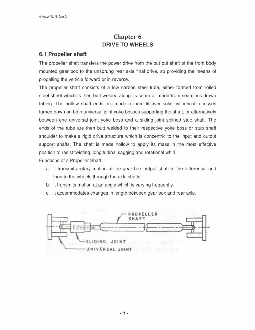
The propeller shaft transfers the power drive from the out put shaft of the front body
mounted gear box to the unsprung rear axle final drive, so providing the means of
propelling the vehicle forward or in reverse.
The propeller shaft consists of a low carbon steel tube, either formed from rolled
steel sheet which is then butt welded along its seam or made from seamless drawn
tubing. The hollow shaft ends are made a force fit over solid cylindrical recesses
turned down on both universal joint yoke bosses supporting the shaft, or alternatively
between one universal joint yoke boss and a sliding joint splined stub shaft. The
ends of the tube are then butt welded to their respective yoke boss or stub shaft
shoulder to make a rigid drive structure which is concentric to the input and output
support shafts. The shaft is made hollow to apply its mass in the most effective
position to resist twisting, longitudinal sagging and rotational whirl.
Functions of a Propeller Shaft:
a. It transmits rotary motion of the gear box output shaft to the differential and
then to the wheels through the axle shafts.
b. It transmits motion at an angle which is varying frequently.
c. It accommodates changes in length between gear box and rear axle.
Drive To Wheels
- 2 -
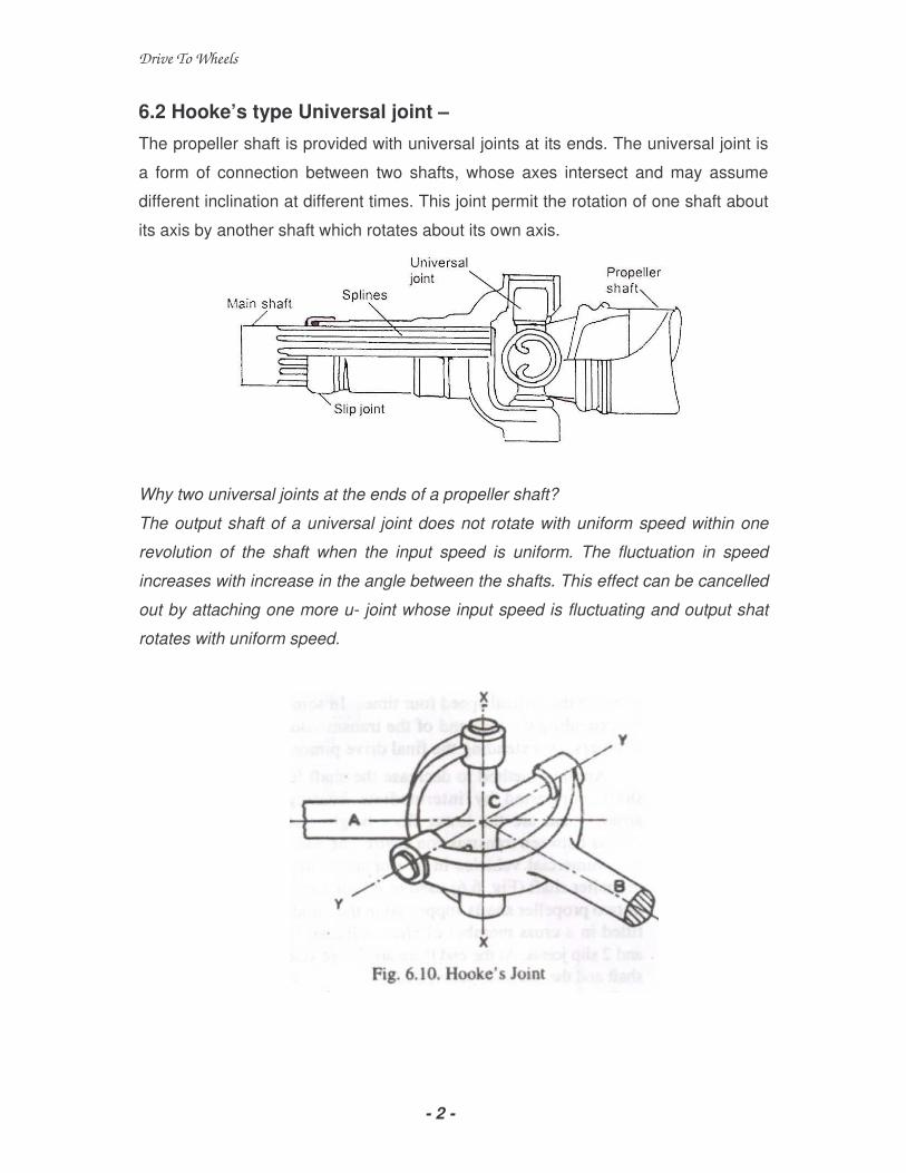
6.2 Hooke’s type Universal joint –
The propeller shaft is provided with universal joints at its ends. The universal joint is
a form of connection between two shafts, whose axes intersect and may assume
different inclination at different times. This joint permit the rotation of one shaft about
its axis by another shaft which rotates about its own axis.
Why two universal joints at the ends of a propeller shaft?
The output shaft of a universal joint does not rotate with uniform speed within one
revolution of the shaft when the input speed is uniform. The fluctuation in speed
increases with increase in the angle between the shafts. This effect can be cancelled
out by attaching one more u- joint whose input speed is fluctuating and output shat
rotates with uniform speed.

Drive To Wheels
- 3 -
6.3 Constant Velocity universal joint:
In vehicles where the front axles are being driven, regulatory of rotation and
transmission of torque at large inclinations are vital. It should be remembered that in
these vehicles, the inclination between the shafts may assume a large value (even
up to 400). In such cases, constant velocity universal joints are used.
The constant velocity universal joint does not
suffer from the variation in the speed of the
driven shaft. The speeds of the shafts
connected by this joint are absolutely equal. It
is shown in the figure below.
A constant velocity universal joint consists of
two yokes with oval races, four driving balls, a
centre ball, a centre ball pin and retainer pin. The driving balls are freely mounted in
the grooves. The centre ball is secured on the pin in one of the yokes. In this unit,
the balls are the driving contact. They move laterally as the joint rotates. The
movement of the balls permits the point of the driving contact between the two
halves of the coupling to remain in a place which bisects the angle between the two
shafts. By this arrangement, the fluctuation in speed of the driven shaft is avoided.
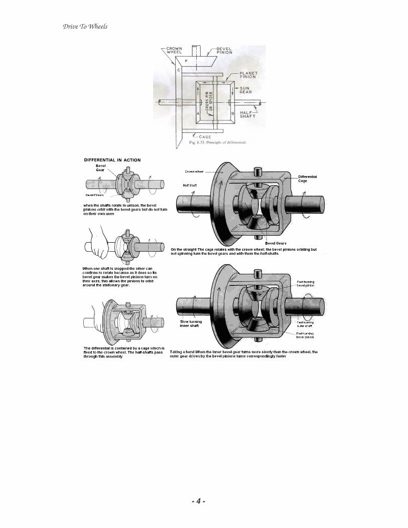
6.4 DIFFERENTIAL GEAR
When a vehicle takes a turn, the outer wheels must travel farther than the inner
wheels. In automobiles, the front wheels can rotate freely on their axles and thus can
adapt themselves to the conditions. However, both rear wheels are driven by the
engine through gearing. Therefore, some sort of automatic device is necessary so that
the two rear wheels are driven at slightly different speeds. This is accomplished by
fitting a differential gear on the rear axle.
Drive To Wheels
- 4 -

Drive To Wheels
- 5 -
The fact that an epicyclic gear has two degrees of freedom has been utilised in the
differential gear of an automobile. It permits the two wheels to rotate at the same
speed when driving straight while allowing the wheels to rotate at different speeds
when taking a turn. Thus a differential gear is a device which adds or subtracts angular
displacements.
Figure shows the arrangements of gears in the differential of an automobile. The shaft
S is driven by the engine through the gear box and has a bevel pinion A keyed to it.
Bevel pinion A meshes with a bevel wheel B which turns loosely on the hub of gear C.
Shafts S1 and S2 form the rear axles to which are fixed the rear wheels, of the
automobile. Gears C and D are keyed to the shafts S1 and S2 respectively. C and D
gear with equal bevel pinions E and F which are free to rotate on their respective axes.
The wheel B carries two brackets that support the bearings for gears E and F.
When the automobile moves in a straight path, the bevel pinion A drives the wheel B.
The whole differential acts as one unit and rotates with the bevel wheel B so that the
wheels C and D rotate with the same speed and in the same direction as B. There is no
relative motion between gears C and D, and E and F. Gears E and F also do not rotate
about their own axes. They act just like keys to transmit motion from B to C and D.
Thus C and D, which are keyed to the shafts that carry the wheels, rotate at the same
speed as B.

Drive To Wheels
- 6 -
When a turn is taken, E and F rotate about their own axes and the system works as an
epicyclic gear giving two outputs at C and D with one input at B.
Action Arm ‘B’ C (Tc) E/F D (TD)
Fix the arm B and give
+1 rev. to C
0
1
- -1
Fix the arm B and give
+1 rev. to C
0
+x
- -x
Give +y rev. to atm B
and +x rev. to C
y y + x - y - x
TC = TD = TE = TF
With reference to the above table, it is seen that the speed of B is the arithmetical mean
of the speeds C and D, because y = {(y+x) + (y-x)}/2. This shows that while taking a
turn, if the speed of C decreases than that of B, there will be a corresponding increase
in the speed of D.
Drive To Wheels
- 7 -
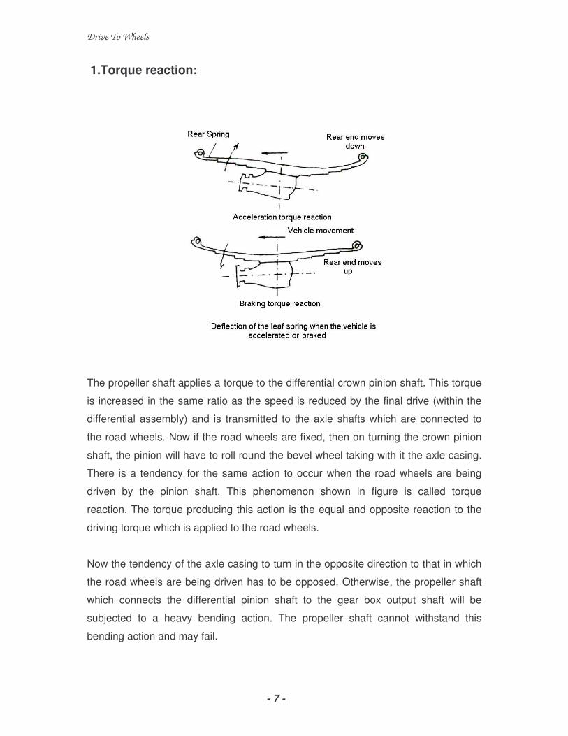
1.Torque reaction:
The propeller shaft applies a torque to the differential crown pinion shaft. This torque
is increased in the same ratio as the speed is reduced by the final drive (within the
differential assembly) and is transmitted to the axle shafts which are connected to
the road wheels. Now if the road wheels are fixed, then on turning the crown pinion
shaft, the pinion will have to roll round the bevel wheel taking with it the axle casing.
There is a tendency for the same action to occur when the road wheels are being
driven by the pinion shaft. This phenomenon shown in figure is called torque
reaction. The torque producing this action is the equal and opposite reaction to the
driving torque which is applied to the road wheels.
Now the tendency of the axle casing to turn in the opposite direction to that in which
the road wheels are being driven has to be opposed. Otherwise, the propeller shaft
which connects the differential pinion shaft to the gear box output shaft will be
subjected to a heavy bending action. The propeller shaft cannot withstand this
bending action and may fail.

Drive To Wheels
- 8 -
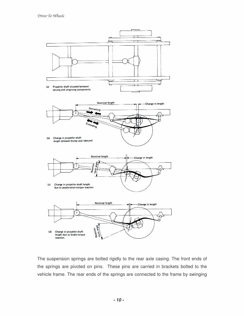
The torque reaction experienced by the vehicle leaf spring and the propeller shaft
while accelerating the vehicle and during braking the vehicle can be seen in figure
below. We can overcome this tendency of the axle casing to turn by attaching an
arm to the casing and securing the front end of this member to the frame of the
vehicle.
Fd – Driving force, Fr – Reaction force, Fb – Braking force,
Tr – Reaction Torque, Tb – Braking torque, Ta – Acceleration Torque
i. Driving Thrust,
ii. Side Thrust,
iii. Torque Reaction and
iv. Braking Torque
Driving Thrust: The driving torque produced in the engine is primarily responsible
for producing driving thrust in the rear road wheels. It has to be transferred from the
rear axle housing to the chassis frame which can be accomplished through, either
(i) A strong rear springs,
(ii) A thrust-taking member such as radial rod.
When springs are used to serve this purpose, they are made strong enough in
addition to their springing action.
Side Thrust. The rear axle is invariably subjected to side thrust (or pull), when the
rear wheels experience any side load. Such situation arises due to cornering force
when the vehicle is negotiating a curve, or when the vehicle is moving over uneven
ground. To combat the side thrust and to hold the axle in its desired position, the
following provisions are generally made.
(i) Taper roller or ball-thrust bearings are used for rear wheel, and
(ii) ‘Panhard rod’ is used between the axle casing and the frame.

Drive To Wheels
- 9 -
Torque Reaction. If the rear axle is held rigidly when the road wheels are prevented
from rotation, (due to driving needs or road conditions) the bevel pinion of the final
drive tends to rotate around the crown wheel. It produces a tendency in the whole
vehicle to rotate about the rear axle or to lift-off the front of the vehicle. This effect is
known as torque-reaction. It gives rise to a force on the axle casing which tries to
rotate it. This effect has to be resisted otherwise springs, frames, and/or the propeller
shaft will be stressed immensely. Therefore, torque members are provided for this
purpose which may be one of the following types.
(i) The stiffened rear springs
(ii) Radius rod
(iii) Spherically ended propeller shaft casing
Braking Torque. The axle casing experiences the ‘brake torque’ when the brakes are
applied to the vehicle. The brake torque is produced in a direction opposite to the
torque-reaction, since the braking effect is reverse of the driving effect.
6.5 TYPES OF DRIVE
1. Hotchkiss drive:
The Hotchkiss is the simplest of the drive systems and is the most widely used. The
arrangement of the parts can be seen in figure.
Drive To Wheels
- 10 -
The suspension springs are bolted rigidly to the rear axle casing. The front ends of
the springs are pivoted on pins. These pins are carried in brackets bolted to the
vehicle frame. The rear ends of the springs are connected to the frame by swinging

Drive To Wheels
- 11 -
links or shackles. This arrangement permits the deflection of the spring when the
vehicle is accelerated or braked.
The propeller shaft is provided with two universal joints one at each end and a sliding
joint at one end. This arrangement permits the rear axle assembly to move up and
down due to projections and depression on the road surface. Engine power is always
transmitted from the gear box to the final drive in the differential through the propeller
shaft. From the differential the driving torque is transmitted to the road wheels
through the axle shafts. In this transmission system, the suspension springs also act
as torque and thrust members.
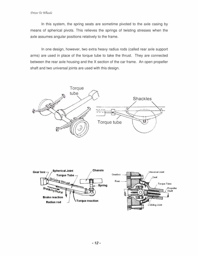
2. Torque tube drive:
The torque tube drive, which is still fairly widely used is shown in figure. There is a
tubular member called torque tube surrounds the propeller shaft and is bolted to the
rear axle casing. The front end of this member is spherical in shape, The spherical
end fits in a cup bolted to a cross member of the vehicle frame ( or to the back of the
gear box). The torque tube incorporates bearings which support the propeller shaft.
The propeller shaft itself is usually made of hollow steel tubing which construction
gives it a light weight and torsional strength. The suspension leaf springs are bolted
to the spring seats that are provided on the axle casing. Each end of the springs is
shackled to the frame. The tubular member will transmit the thrust from the axle to
the frame and will also take the torque reaction. Often radius rods are used to assist
the torque tube to take the twist and thrust of the vehicle drive.
With this construction, the centre line of the final drive bevel pinion shaft will always
pass through the centre of the spherical cup. Now, if the propeller shaft is connected
to the gear box shaft by a universal joint situated exactly at the centre of that cup, no
other universal joint will be needed and no sliding joint will be necessary. This is
because both pinion shaft and propeller shaft will move about the same centre,
namely that of the spherical cup, when the axle moves up and down.
Drive To Wheels
- 12 -
In this system, the spring seats are sometime pivoted to the axle casing by
means of spherical pivots. This relieves the springs of twisting stresses when the
axle assumes angular positions relatively to the frame.
In one design, however, two extra heavy radius rods (called rear axle support
arms) are used in place of the torque tube to take the thrust. They are connected
between the rear axle housing and the X section of the car frame. An open propeller
shaft and two universal joints are used with this design.

Drive To Wheels
- 13 -
Hotchkiss drive versus Torque tube drive:
Description
Hotchkiss drive
Torque tube drive
Number of universal joint
Slip joint in propeller
shaft
Posture of Propeller
Effect on propeller shaft
Spring support
Geometry of spring
Load on spring
Effect on final drive shaft
Two
Needed
Open
Can bend, length
changes
One end fixed and the
other in Shackle
Deflects
Torque and brake
reactions, driving and
side thrusts
Position alters
One
Not needed
Enclosed within the
torque tube
Cannot bend, no change
in length
Both ends in shackle
Does not deflect.
Side thrust only
No shift in position
]6.6 FRONT AXLES
Stub axle and wheel
mounting:
In solid stub axle suspension,
axle beam is connected to wheel
spindle by means of king pins, or
spindle bolt.
Drive To Wheels
- 14 -
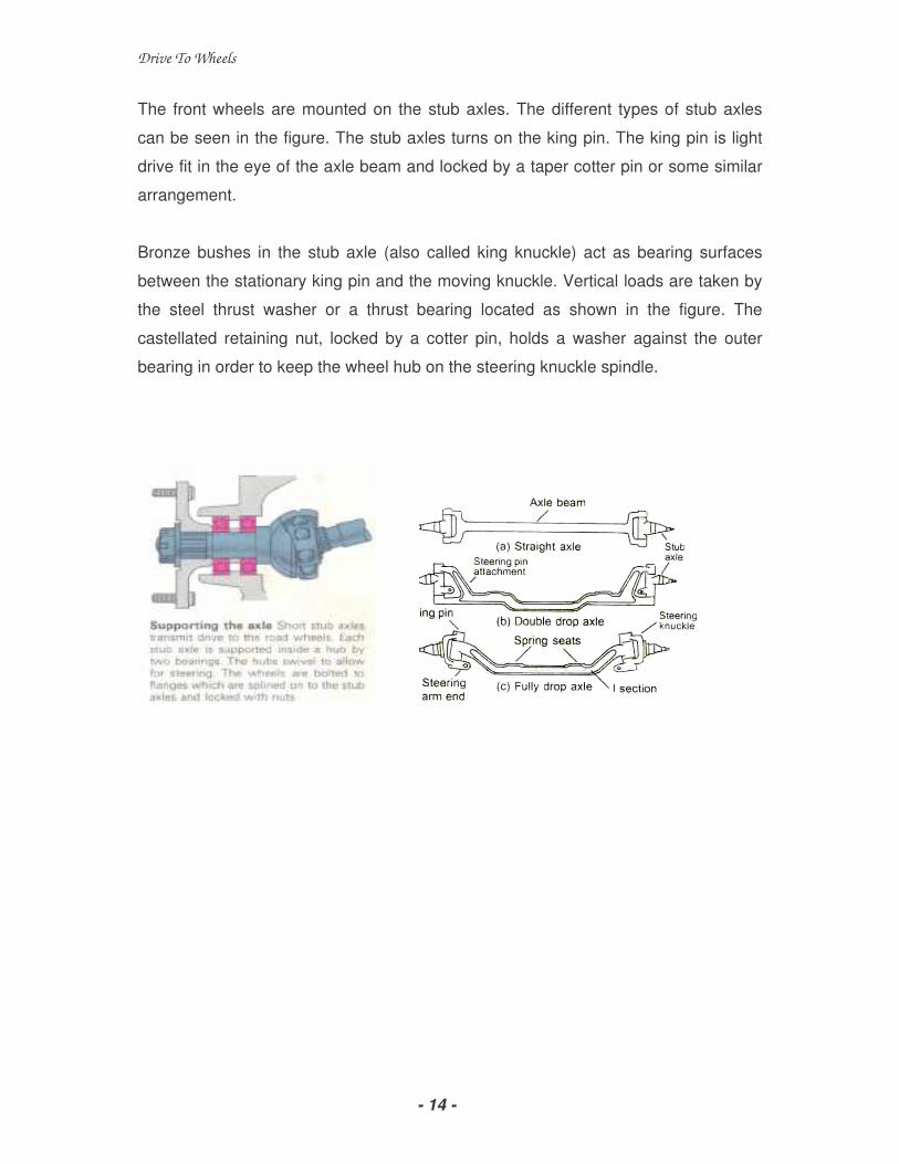
The front wheels are mounted on the stub axles. The different types of stub axles
can be seen in the figure. The stub axles turns on the king pin. The king pin is light
drive fit in the eye of the axle beam and locked by a taper cotter pin or some similar
arrangement.
Bronze bushes in the stub axle (also called king knuckle) act as bearing surfaces
between the stationary king pin and the moving knuckle. Vertical loads are taken by
the steel thrust washer or a thrust bearing located as shown in the figure. The
castellated retaining nut, locked by a cotter pin, holds a washer against the outer
bearing in order to keep the wheel hub on the steering knuckle spindle.

Drive To Wheels
- 15 -
6.7 REAR AXLE
1. Semi floating axle:
The semi floating rear axle is shown in the
figure. The short rear axle shaft inner end
is supported only by the differential side
gear. The differential case carries the inner
bearing between it and the axle shaft
housing that supports it. The inner end of
the axle shaft is thus relived of the task of
supporting the weight of the vehicle. The
weight of the vehicle is supported by the axle housing. Now the outer end of the axle
supports the weight of the vehicle and takes up the thrust. Hence, this construction is
called Semi floating axle.

Drive To Wheels
- 16 -
The inner end of the axle shaft is splined to the differential side gear. The outer end
is flanged and the wheel is bolted directly to it. In some designs, the hub of the wheel
is keyed to the outer end of the axle shaft. The axle housing supports the wheel
bearing, which is placed inside the outer end of the axle housing. The bearing is held
on the axle by a retainer. Most axle bearings are pre-lubricated. With this
arrangement, the brake drum, the wheel, and the bearing retainer plate must be
removed in order to withdraw the axle shaft. This arrangement results in the axle
shaft helping to support the weight of the vehicle in addition to transmitting rotation to
the wheels

Drive To Wheels
- 17 -
In a semi floating axle the various forces acting on the half shaft are:-
• Side thrusts when a vehicle negotiates a corner.
• Shear force and bending movement due to weight of the vehicle.
• Twisting caused due to driving and braking torques.
Such axle has been used on Tata Sierra, Tata estate, Standard 20 van, FIAT 1100
car etc.
2. Three quarter floating axle
The three quarter floating axle is shown in figure. In this axle, the wheel hub is
supported by a single bearing located in the centre of the wheel hub. The wheel hub
runs on the axle housing. The axle shaft is keyed rigidly to the wheel hub. This
arrangement provides the driving connection and maintains the alignment of the
wheel.
The construction at the inner end of the axle shaft is the same as with the semi
floating type. This axle is not supported by bearings at either end. The three quarter
floating axle has only one bearing at the outer end. It is not as quite as the full
floating type.

Drive To Wheels
- 18 -
The Three-quarter floating axle sustains the following loads:-
• Bending load due to side thrust when the vehicle is cornering, and
• Twisting caused due to driving and the braking thrusts.
It has been employed on various Ambassador Car models.

Drive To Wheels
- 19 -
3. Full floating axle
The full floating axle is
shown in figure. In this axle, the
wheel hub is supported by two
bearings. The bearings are
running directly upon the axle
housing. The axle shaft is fastened
to the wheel hub flange by means
of a coupling. Through the
coupling, the rotary motion of the
axle shaft is transmitted to the hub
and the wheel. With this arrangement, the axle shaft can be removed from the
housing without disturbing the wheel by removing the hub cap and the coupling.
In the full floating axle, the axle shaft is not supported at either end by
bearings. The position of the axle shaft is maintained by the way that it is supported
at both ends. As such, the axle is relieved of all strain caused by the weight of the
vehicle or end thrusts. Now, the only function of the axle shaft is to transmit the
rotary motion or torque to the wheel. Because of this fact, the axle is called full
floating.
Full floating axle is the only construction that holds the wheel in position even
when the axle shaft breaks. In other types, the wheel comes off and causes the
vehicle to drop. The full floating axle is used almost exclusively in trucks. In all
applications, in axle constructions either tapered roller or ball bearings are used.
A fully floating axle can be replaced even without a jack as the vehicle will
remain standing on its wheels. If needed the vehicle can be towed even with a
broken axle. The mounting system of fully floating axle is strong and robust in
construction but is very costly. It has been employed on Tata LPT 2213- 6x2 trucks,
Premier road master, Mahindra MM540 jeep, Ford FS16 truck etc.

Drive To Wheels
- 20 -
6.8 Comparison of different types of rear axles:
Description
Full-floating rear
axle
Three-quarter floating
rear axle
Semi-floating rear
axle
Cost
Vertical load taken
Side load
Driving torque to
the wheels
Application
Bearing Placement
High
Nil
Nil
Yes
In heavy vehicles
Over the axle
casing
Medium
Yes, by a single
bearing placed over
the axle
casing Present
Yes
More in cars
Over the axle casing
Low
Yes, taken by half-
shaft bearings
Present
Yes
In medium vehicles
Within the axle
casing
Drive To Wheels
- 21 -
Exercise 6
1. Draw and explain Propeller shaft.
2. Explain with a neat diagram universal joint
3. With a neat sketch explain briefly working of Differential.
4. Write a short note on
i. Driving Thrust,
ii. Side Thrust,
iii. Torque Reaction and
iv. Braking Torque
5. Diffrentiate between Hotchkiss drive& Torque tube drive with a neat sketch.
6. Explain with a neat diagram Three quarter floating axle
7. Compare the Semi floating, Three quarter floating and Full floating axle.